PMAC9900产品说明书
PMAC9900E_modbus通讯协议
PMAC®9900E标准电量监测仪MODBUS串行通信协议ZHUHAI PILOT ELECTRONICS Co.,LtdDoc.No.03-0304-002珠海派诺电子有限公司目录第一章简介 ----------------------------------------------------------------------------------2 11串行通讯协议的目的----------------------------------------------------------21 2 MODBUS通讯协议的版本 ------------------------------------------------------2第二章PMAC®9900E-MODBUS串行通讯协议详细说明-----------------------------22 1 协议基本规则 ---------------------------------------------------------------------22 2 传送模式 ---------------------------------------------------------------------------22 3 包裹结构 ---------------------------------------------------------------------------223 1 地址域 --------------------------------------------------------------------323 2 功能码域 -----------------------------------------------------------------323 3 数据域 --------------------------------------------------------------------323 4 校验域 --------------------------------------------------------------------32 4 网络时间 ---------------------------------------------------------------------------32 5 异常响应 ---------------------------------------------------------------------------32 6 广播命令 ---------------------------------------------------------------------------4第三章通信包裹 -----------------------------------------------------------------------------43 1 16位/32位数据通讯模式 -------------------------------------------------------43 2 读寄存器包裹 -------------------------------------------------------------------43 3 写寄存器包裹 -------------------------------------------------------------------5 第四章计算CRC-16校验码----------------------------------------------------------------7 第五章 PMAC®9900E寄存器说明 -------------------------------------------------------8附录A PMAC®9900E-MODBUS寄存器表 ---------------------------------------8 附录B 符号寄存器含义 --------------------------------------------------------------13 附录C 数据单位 -----------------------------------------------------------------------13 附录A 有关继电器的操作 -----------------------------------------------------------14第六章通信包裹范例---------------------------------------------------------------------- 14第一章 简介通信协议详细地描述了PMAC®9900E在MODBUS通讯模式下的输入和输出命令信息和数据以便第三方使用和开发1 1 串行通讯协议的作用通信协议的作用使信息和数据在上位机主站和PMAC®9900E之间有效地传递它包括1允许主站访问和设定所连接PMAC®9900E的全部设置参数2允许访问PMAC®9900E的所有测量数据和事件纪录1 2 MODBUS通讯协议的版本该通讯协议适用于本公司已经出厂的所有各种版本的PMAC®9900E仪表对于日后的系列若有改动会加以特别说明第二章 PMAC®9900E-MODBUS 串行通信协议详细说明2 1 PMAC®9900E-MODBUS协议基本规则以下规则确定在RS485或者RS232C回路控制器和其他RS485串行通信回路中设备的通信规则1所有RS485回路通信应遵照主/从方式在这种方式下信息和数据在单个主站和最多32个从站监控设备之间传递2主站将初始化和控制所有在RS485通信回路上传递的信息3无论如何都不能从一个从站开始通信4所有RS485环路上的通信都以打包方式发生一个包裹就是一个简单的字符串每个字符串8位一个包裹中最多可含255个字节组成这个包裹的字节构成标准异步串行数据并按8位数据位1位停止位无校验位的方式传递串行数据流由类似于RS232C 中使用的设备产生5主站发送包裹称为请求从站发送包裹称为响应6任何情况从站只能响应主站一个请求2 2 传送模式MODBUS协议可以采用ASCII或者RTU模式传送数据PMAC®9900E仅仅支持RTU 模式8位数据位无校验位1位停止位2 3 MODBUS包裹结构描述每个MODBUS包裹都由以下几个部分组成1地址域2功能码域3数据域4校验域23 1 地址域MODBUS的从站地址域长度为一个字节包含包裹传送的从站地址有效的从站地址范围从1~247从站如果接收到一帧从站地址域信息与自身地址相符合的包裹时应当执行包裹中所包含的命令从站所响应的包裹中该域为自身地址23 2 功能码域MODBUS包裹中功能域长度为一个字节用以通知从站应当执行何操作从站响应包裹中应当包含主站所请求操作的相同功能域字节有关PMAC®9900E的功能码参照下表功能码含义功能0x03 读取寄存器获得当前PMAC®9900E内部一个或多个当前寄存器值0x10 设置寄存器将指定数值写入PMAC®9900E内部一个或多个寄存器内23 3 数据域MODBUS数据域长度不定依据其具体功能而定MODBUS数据域采用”BIG INDIAN”模式即是高位字节在前低位字节在后举例如下Example 2.11个16位寄存器包含数值为0x12AB寄存器数值发送顺序为高位字节 =0x12低位字节 =0x0AB23 4 校验域MODBUS-RTU模式采用16位CRC校验发送设备应当对包裹中的每一个数据都进行CRC16计算最后结果存放入检验域中接收设备也应当对包裹中的每一个数据除校验域以外进行CRC16计算将结果域校验域进行比较只有相同的包裹才可以被接受具体的CRC校验算法参照附录2 4 网络时间考虑在RS485网络上传送包裹需要遵循以下有关时间的规定1主站请求包裹结束到从站响应包裹开始之间的时间最小为20毫秒最大为250毫秒典型值为60毫秒2从站响应包裹结束到主站下一请求包裹开始之间的时间在16位模式下典型值为100毫秒在32位模式下典型值为500毫秒3包裹中相邻两个字节之间的最大时间依据通讯波特率不同而不同一般来说最大字节时间为3倍的字节发送时间例如9600波特率下字节间隔为3毫秒4800波特率时字节间隔为6毫秒2 5 异常响应如果主站发送了一个非法的包裹给PMAC®9900E或者是主站请求一个无效的数据寄存器时异常的数据响应就会产生这个异常数据响应由从站地址功能码故障码和校验域组成当功能码域的高比特位置为1时说明此时的数据帧为异常响应下表说明异常功能码的含义功能码该码表示从站接收到非法的功能码或者是接收到一个错误的操作密码接收到无效的数据地址或者是请求寄存器不在有效的寄存器范围内2 6 广播命令PMAC®9900E-MODBUS协议不支持广播命令第三章通讯包裹PMAC®9900E-MODBUS支持两个功能码标准的MODBUS协议仅支持16位数据模式也就说传输任何测量值最大为65535为了支持传输更大的测量值PMAC®9900E提供了扩展的32位数据模式3.1节将描述16位数据模式与32位数据模式的不同 3.2节将说明PMAC®9900E的读数据包裹和响应包裹的格式 3.3节将说明PMAC®9900E写数据包裹和响应包裹的格式3 1 16位/32位数据通讯模式16位数据模式中所有的数据都是通过一个16位寄存器表示即使实际数值超过65535但是传输的最大值只能为6553532位模式中所有的数据都是依照如下规则组织的1除电能参数以外的实时数据和设置参数都是用两个寄存器说明高位寄存器 =实际值 / 10000 商值低位寄存器 =实际值 / 10000 余数这种设定方式是为了兼容MODICON的PLC装置2符号寄存器高位寄存器固定位0低位寄存器仍然保持原有数据3电能数据不论采用16位或者32位数据模式都可以采用两个寄存器表示16位数据模式高16位 =实际值 / 1000 商值低16位 =实际值 / 1000 余数32位数据模式:高32位寄存器高16位 =0低16位 =实际值 / 1000000 商值低32位寄存器高16位 =实际值 / 10000 / 100 余数低16位 =实际值 / 10000 余数在16位数据模式下电能数据最大为65000MWH在32位数据模式下电能数据最大为2000GWH3 2 读寄存器功能码03由主站机发送的包裹请求PMAC®9900E响应所有有效的寄存器在起始寄存器和终止寄存器之间一般读寄存器不需要密码但在以下两种情况下需要正确的密码1去读一个被保护的寄存器目前唯一被保护的寄存器是保护仪表密码的寄存器2如果只读保护寄存器地址43017已设置那么密码正确才能读任何寄存器在响应包裹中仅仅有效的寄存器才能被发送PMAC®9900E没有配置的寄存器或对该输入电压模式下不存在的寄存器将不被发送由于MODBUS协议中并没有专门的密码域所以执行与密码相关的操作时需要执行一个特殊的操作首先采用写寄存器功能码将密码写入密码寄存器中地址43051无论写入密码是否正确PMAC®9900E都会做出响应此时用户在执行需要操作的功能如果先前的写入密码不正确则响应的包裹为异常如果写入密码正确则PMAC®9900E会响应正常的数据16位模式读寄存器包裹格式主机PMAC®9900E响应格式PMAC®9900E主机从站地址1字节从站地址1字节功能码03H 1字节功能码03H 1字节起始寄存器地址2字节字节数2*寄存器数目1字节寄存器个数2字节第一个寄存器数据2字节CRC校验码2字节第二个寄存器数据2字节…………CRC校验码2字节32位模式读寄存器包裹格式主机PMAC®9900E响应格式PMAC®9900E主机从站地址1字节从站地址1字节功能码03H 1字节功能码03H 1字节起始寄存器地址2字节字节数2*寄存器数目1字节寄存器个数2字节第一个寄存器数据高位字2字节CRC校验码2字节第一个寄存器数据低位字2字节第二个寄存器数据高位字2字节第二个寄存器数据低位字2字节…………CRC校验码2字节注意1响应包裹中只会包含有效的寄存器那些未配置的寄存器和无效的寄存器都不会被仪表发送上来所以用户首先要确定仪表中所配置的寄存器例如如果用户需要请求40046寄存器数据而且当前PMAC®9900E并未配置该寄存器则仪表将会将40055寄存器数据送上假定仪表在40046寄存器后配置的第一个有效寄存器是400552 32位数据模式下请求寄存器数目是16位数据模式下的2倍例如在32位模式下请求10个参数需要20个寄存器但在16位模式下只需要10个寄存器3 3 写寄存器功能码16该命令允许主站配置PMAC®9900E工作参数以下为数据格式16位模式响应格式PMAC®9900E主机写寄存器包裹格式主机PMAC®9900E从站地址1字节从站地址1字节功能码10H 1字节功能码10H 1字节起始寄存器地址2字节起始寄存器地址2字节寄存器个数2字节寄存器个数2字节1字节CRC校验码2字节字节个数2*寄存器个数第一个寄存器数据第二个寄存器数据……….CRC校验码2字节32位模式响应格式PMAC®9900E主机写寄存器包裹格式主机PMAC®9900E从站地址1字节从站地址1字节功能码10H 1字节功能码10H 1字节起始寄存器地址2字节起始寄存器地址2字节寄存器个数2字节寄存器个数2字节1字节CRC校验码2字节字节个数2*寄存器个数第一个寄存器数据高位字第一个寄存器数据低位字第二个寄存器数据高位字第二个寄存器数据低位字……….CRC校验码2字节注意1 PMAC®9900E假定写入的寄存器从第一个寄存器开始是连续的2 32位模式下写入的寄存器数目是16位模式的两倍例如在32位模式下写10个参数需要20个寄存器而在16位模式下只需要10个寄存器第四章计算CRC-16该部分将描述计算CRC-16的过程在帧中的有关的字节被义为是一串2进制数据(0,1)第16位校验和是这样得到的该串数据流被216乘然后除以发生器多项式该式以2进制表示为1100000000000101商被忽略16位的余数就是CRC的值在计算CRC-16值时全部算术运算用modulo two或者异或XOR算法按照下列步骤产生CRC-16的校验和1省略发生器最有意义的位并且把位的顺序颠倒过来形成一个新的多项式结果是1010000000000001或者16进制的A0012将全部1或者16进制FFFF装入16位寄存器3用16位寄存器中低阶字节对第一个数据字节进行XOR运算把结果存入16位寄存器4把16位寄存器向右移一位如果溢出位为1则转向第5步骤否则转向第6步骤5用新的发生器多项式对16位寄存器执行MOR运算并且把结果存入16步骤6重复步骤4直到移位8次为止7用16位寄存器的第阶字节对下一个数据字节进行XOR运算将结果存入16位寄存器8重复步骤4-7直到小包的所有字节都已经用16位寄存器执行了XOR运算为止916位寄存器的内容就是CRC-16下面的例子是对16进制的6403这个字节进行CRC计算步骤 字节 动作 寄存器 位# 移位2 初值 1111 1111 1111 11111 装入第一字节 0000 0000 0110 01003 异或 1111 1111 1001 10114 右移一位 0111 1111 1100 1101 1 15a 异或多项式 1101 1111 1100 11004 右移一位 0110 1111 1110 0110 2 04 右移一位 0011 0111 1111 0011 3 04 右移一位 0001 1011 1111 1001 4 15a 异或多项式 1011 1011 1111 10004 右移一位 0101 1101 1111 11005 04 右移一位 0010 1110 1111 1110 6 04 右移一位 0001 0111 0111 1111 7 04 右移一位 0000 1011 1011 1111 8 15a 异或多项式 1010 1011 1011 11102 装入第二字节 0000 0000 0000 00117 异或 1010 1011 1011 11014 右移一位 0101 0101 1101 1110 1 15a 异或多项式 1111 0101 1101 11114 右移一位 0111 1010 1110 1111 2 15a 异或多项式 1101 1010 1110 11104 右移一位 0110 1101 0111 0111 3 04 右移一位 0011 0110 1011 1011 4 15a 异或多项式 1001 0110 1011 10104 右移一位 0100 1011 0101 11015 04 右移一位 0010 0101 1010 1110 6 15a 异或多项式 1000 0101 1010 11114 右移一位 0100 0010 1101 0111 7 15a 异或多项式 1110 0010 1101 01104 右移一位 0111 0001 0110 1011 8 0CRC-16 0111 0001 0110 1011第五章 PMAC®9900E寄存器说明所有的PMAC®9900E寄存器包括实时寄存器和设置寄存器在MODBUS通讯协议时都具有4XXXX的基址根据MODBUS协议请求PMAC®9900E中一个地址为4XXXX 的寄存器时主站实际读取为XXXX-1例如请求PMAC®9900E中40011寄存器主站实际寄存器号为10下表说明在不同电压模式下部分实时寄存器的状态发生了变化原有的有效寄存器变为无效寄存器电压模式寄存器描述WYE DEMO 3-WIRE DELTA40011 A相电压有效无效40012 B相电压有效无效40013 C相电压有效无效40014 相电压平均值有效无效40031 A相有功功率有效无效40032 B相有功功率有效无效40033 C相有功功率有效无效40035 A相无功功率有效无效40036 B相无功功率有效无效40037 C相无功功率有效无效40039 A相功率因数有效无效40040 B相功率因数有效无效40041 C相功率因数有效无效40043 A相视在功率有效无效40044 B相视在功率有效无效40045 C相视在功率有效无效附录 A PMAC®9900E-MODBUS寄存器表格表F –1 PMAC®9900E数据寄存器寄存器号寄存器类型描述标准配置Basic可选Optical40011 RO A相相电压 Basic40012 RO B相相电压Basic40013 RO C相相电压Basic40014 RO 相电压平均值Basic40015 RO AB线电压Basic40016 RO BC线电压Basic40017 RO CA线电压Basic40018 RO 线电压平均值Basic40021 RO A相电流Basic40022 RO B相电流Basic40023 RO C相电流Basic40024 RO 相电流平均值Basic40031 RO A相有功功率Basic40032 RO B相有功功率Basic40033 RO C相有功功率Basic40034 RO 三相有功功率Basic40035 RO A相无功功率Basic40036 RO B相无功功率Basic40037 RO C相无功功率Basic40038 RO 三相无功功率Basic40039 RO A相功率因数Basic40040 RO B相功率因数Basic40041 RO C相功率因数Basic40042 RO 功率因数总计Basic40043 RO A相视在功率Basic40044 RO B相视在功率Basic40045 RO C相视在功率Basic40046 RO 三相视在功率Basic40048 RO 系统频率Basic40050 RO 符号寄存器Basic40051 RO 有功电度输入KWH Basic40052 RO 有功电度输入MWH Basic40053 RO 有功电度输出KWH Basic40054 RO 有功电度输出MWH Basic40055 RO 有功电度净值KWH Basic40056 RO 有功电度净值MWH Basic40061 RO 无功电度输入KV ARH Basic40062 RO 无功电度输入MV ARH Basic40063 RO 无功电度输出KV ARH Basic40064 RO 无功电度输出MV ARH Basic40065 RO 无功电度净值KV ARH Basic40066 RO 无功电度净值MV ARH Basic40071 RO 视在电度净值KV AH Basic40072 RO 视在电度净值MV AH Basic表 F-2 状态寄存器寄存器号寄存器类型描述标准配置Basic可选Optical40902 RO 开关量S1状态Basic 40903 RO 开关量S2状态Basic 40904 RO 开关量S3状态Basic 40905 RO 开关量S4状态Basic 40906 RW 继电器RL1状态Basic 40907 RW 继电器RL2状态Basic 40908 RW 继电器RL3状态Basic 40909 RW 继电器RL4状态Basic 40910 RW 继电器RL1控制模式Basic 40911 RW 继电器RL2控制模式Basic 40912 RW 继电器RL3控制模式Basic 40913 RW 继电器RL4控制模式Basic 40914 RW 继电器RL1延时动作时间Basic 40915 RW 继电器RL2延时动作时间Basic 40916 RW 继电器RL3延时动作时间Basic 40917 RW 继电器RL4延时动作时间Basic 40918 RW 继电器RL1延时复归时间Basic 40919 RW 继电器RL2延时复归时间Basic 40920 RW 继电器RL3延时复归时间Basic 40921 RW 继电器RL4延时复归时间Basic40922 RO 继电器RL1上限报警标志Basic 40923 RO 继电器RL1下限报警标志Basic 40924 RO 继电器RL2上限报警标志Basic 40925 RO 继电器RL2下限报警标志Basic 40926 RO 继电器RL3上限报警标志Basic 40927 RO 继电器RL3下限报警标志Basic 40928 RO 继电器RL4上限报警标志Basic 40929 RO 继电器RL4下限报警标志Basic表 F-3 特殊功能寄存器寄存器号寄存器类型描述标准配置Basic可选Optical43002 RW PT一次侧电压Basic 43003 RW PT二次侧电压Basic 43004 RW CT一次侧电流Basic43005 RW C电压输入模式0123或4Basic43006 RW 设备号Basic43007 RW 波特率300120024004800960019200Basic43008 保留43009 RW 对比度视觉调节Basic 43010 RW 密码Basic 43011 WO 复位所有最小/最大值Basic 43012 WO 复位所有时间计数器如千瓦时Basic 43013 RO 版本号Basic 43014 RO 最新版本日期Basic 43015 RO 特征码Basic 43016 RO 设备类型Basic 43017 RW 允许只读保护YES OR NOBasic 43018 保留43019 RW 1#继电器设定V A上限值Basic 43020 RW 1#继电器设定V A下限值Basic 43021 RW 1#继电器设定VB上限值Basic 43022 RW 1#继电器设定VB下限值Basic 43023 RW 1#继电器设定VC上限值Basic 43024 RW 1#继电器设定VC下限值Basic 43025 RW 1#继电器设定IA上限值Basic43027 RW 1#继电器设定IB上限值Basic 43028 RW 1#继电器设定IB下限值Basic 43029 RW 1#继电器设定IC上限值Basic 43030 RW 1#继电器设定IC下限值Basic 43031 RW 1#继电器设定频率上限值Basic 43032 RW 1#继电器设定频率下限值Basic 43033 RW 2#继电器设定V A上限值Basic 43034 RW 2#继电器设定V A下限值Basic 43035 RW 2#继电器设定VB上限值Basic 43036 RW 2#继电器设定VB下限值Basic 43037 RW 2#继电器设定VC上限值Basic 43038 RW 2#继电器设定VC下限值Basic 43039 RW 2#继电器设定IA上限值Basic 43040 RW 2#继电器设定IA下限值Basic 43041 RW 2#继电器设定IB上限值Basic 43042 RW 2#继电器设定IB下限值Basic 43043 RW 2#继电器设定IC上限值Basic 43044 RW 2#继电器设定IC下限值Basic 43045 RW 2#继电器设定频率上限值Basic 43046 RW 2#继电器设定频率下限值Basic 43047 RW 3#继电器设定V A上限值Basic 43048 RW 3#继电器设定V A下限值Basic 43049 RW 3#继电器设定VB上限值Basic 43050 RW 3#继电器设定VB下限值Basic 43051 RW 3#继电器设定VC上限值Basic 43052 RW 3#继电器设定VC下限值Basic 43053 RW 3#继电器设定IA上限值Basic 43054 RW 3#继电器设定IA下限值Basic 43055 RW 3#继电器设定IB上限值Basic 43056 RW 3#继电器设定IB下限值Basic 43057 RW 3#继电器设定IC上限值Basic 43058 RW 3#继电器设定IC下限值Basic 43059 RW 3#继电器设定频率上限值Basic 43060 RW 3#继电器设定频率下限值Basic 43061 RW 4#继电器设定V A上限值Basic 43062 RW 4#继电器设定V A下限值Basic 43063 RW 4#继电器设定VB上限值Basic 43064 RW 4#继电器设定VB下限值Basic43066 RW 4#继电器设定VC下限值Basic43067 RW 4#继电器设定IA上限值Basic43068 RW 4#继电器设定IA下限值Basic43069 RW 4#继电器设定IB上限值Basic43070 RW 4#继电器设定IB下限值Basic43071 RW 4#继电器设定IC上限值Basic43072 RW 4#继电器设定IC下限值Basic43073 RW 4#继电器设定频率上限值Basic43074 RW 4#继电器设定频率下限值Basic注意对PMAC®9900E_rly2而言, 如果读到和#3#4继电器相关的寄存器PMAC®9900E将返回数据0附录 B 符号寄存器含义由于MODBUS数据为16位无符号字所以当用户需要判断功率以及电度的正负情况时就必须借助于符号寄存器40050进行以下为符号寄存器的定义位号寄存器位号寄存器D0 40031 D1 40032D2 40033 D3 40034D4 40035 D5 40036D6 40037 D7 40038D8 40039 D9 40040D10 40041 D11 40042D12 无效D13 无效D14 40055,40056 D15 40065,40066相应位为1说明对应的寄存器数据符号为负为0说明为正附录C 数据单位标准PMAC®9900E协议中的各项实时数据单位如下表所示用户解释数据时请参照名称单位分辨率电压伏特1V电流安培1A有功功率千瓦1KW无功功率千乏1KVar视在功率千伏安1KV A功率因数0.001频率赫兹0.1Hz有功电度千瓦小时1KWH无功电度千乏小时1KvarH视在电度千伏安小时1KV AH继电器延时时间秒1S附录D 有关继电器的操作PMAC®9900E通讯协议可以直接控制仪表继电器的工作状态和设置继电器的定值参数以下说明与继电器控制有关寄存器的含义1继电器状态寄存器该寄存器可读可写读时反映当前继电器的闭合或断开状态写时可以直接操作继电器的闭合和断开用户如果远端控制继电器时可以直接操作该寄存器一旦直接操作状态寄存器则继电器进入手动模式2继电器模式寄存器该寄存器可读可写反映当前继电器的控制是处于手动模式还是自动模式有关的定义参照仪表说明书数值为1表示继电器为手动模式为0表示继电器为自动模式手动模式下有关继电器的编程参数不再发挥作用3继电器报警标志寄存器该寄存器只能读当继电器处于自动模式下有效反映由于何种监测参数出现异常产生继电器动作具体的定义如下D6 D5 D4 D3 D2 D1 D0频率C相电流B相电流A相电流C相电压B相电压A相电压相应位为1表示该参量报警为0表示无报警信息第六章通信包裹范例以下采用几个实际的PMAC®9900E通讯范例说明协议的格式要求6.1 读寄存器范例1这是一个从主站向设备号UNIT为100的PMAC®9900E读请求的范例请求从40011寄存器开始连续20个寄存器数PMAC®9900E设置工作于DEMO模式三相四线星形和三相三线星形格式相同寄存器设置为16位模式主站请求地址功能域起始地址寄存器数目CRC校验64 03 000A 0014 6C32PMAC®9900E响应地址功能码字节数目40011 40012 4001364 03 10 015F 015F 015F40014 40015 40016 40017 40018 40021 015F 0260 0260 0260 0260 03EE 40022 40023 40024 40031 40032 40033 03EE 03EE 03EE 0144 0144 0144 40034 40035 40036 40037 40038 CRC校验03CC 008C 008C 008C 01A4 DB54注意请求连续的寄存器时如果其中包含有无效寄存器PMAC®9900E响应包裹将跳过无效寄存器顺序返回以同等个数的相临有效寄存器中数据6.2 读寄存器范例2这是一个从主站向设备号UNIT为100的PMAC®9900E读请求的范例请求从40011寄存器开始连续20个寄存器数PMAC®9900E设置工作于三角形模式寄存器设置为16位模式主站请求地址功能域起始地址寄存器数目CRC校验64 03 000A 0014 6C32PMAC®9900E响应地址功能码字节数目40015 40016 4001764 03 10 0000 0000 000040018 40021 40022 40023 40024 40034 0000 0000 0000 0000 0000 0000 40038 40042 40046 40048 40050 40051 0000 0000 0000 0000 0F00 029B 40052 40053 40054 40055 40056 CRC校验002F 0000 0000 029B 002F 8840注意请求连续的寄存器时如果从无效寄存器开始请求PMAC®9900E响应包裹将跳过无效寄存器从相临的有效寄存器开始返回同等个数的寄存器数据6.3 读寄存器范例3这是一个从主站向设备号UNIT为100的PMAC®9900E读请求的范例读取从40902到409094个开关量和4个继电器的状态PMAC®9900E设置工作于DEMO模式其他模式相同寄存器设置为16位模式主站请求地址功能域起始地址寄存器数目CRC校验64 03 0385 0008 5C54PMAC®9900E响应地址功能码字节数目40902 40903 4090464 03 10 0000 0000 000040905 40906 40907 40908 40909 CRC校验0000 0000 0000 0000 0000 B69D6.4 写寄存器范例1这是一个写寄存器范例来设置继电器的状态UNIT ID 100主站将写以下信息到PMAC®9900寄存器设置为16位模式1#继电器状态00002#继电器状态0001远程操作3#继电器状态00004#继电器状态0000从主站写命令地址功能码起始地址寄存器数目字节数目40906 4090764 10 0389 0004 08 0000 0001 40908 40909 CRC校验0000 0000 3530从PMAC®9900E响应地址功能域起始地址寄存器数目CRC校验64 10 0389 0004 19916.5 写寄存器范例2这是一个写寄存器范例来设置电压量程电流量程和仪表的电压模式UNIT ID 100主站将写以下信息到PMAC®9900寄存器设置为16位模式PT初级电压1200PT次级电压120CT初级电流5000电压模式0从主站写命令地址功能码起始地址寄存器数目字节数目43002 4300364 10 0BB9 0004 08 04B0 0078 43004 43005 CRC校验0388 0000 C7A4从PMAC®9900E响应地址功能域起始地址寄存器数目CRC校验64 10 0BB9 0004 1BFE。
智能电力监测仪使用说明书
3.2.4
电能参数显示在“电压-电流”栏旁边的“电能参数”栏,“功能”键用于查看2个标准的电能参数及其它选项的电能参数,按“功能”键将依次选择每个电能参数,所有功能选择完毕,显示将循环到第一个功能状态。
1、功能或相显示消失
图2.7.1RS485通讯连接
2.8
精度漂移为每年0.1%。精度校验时间间隔由用户的精度要求决定。有关精度校验请与本公司联系。
2.9
仪表发生故障一般采用整机更换的方法,但在初次安装时应作好以下工作,以保证维护尽可能方便。
1、应提供一个CT短接盒,这样使PMAC9900的电流输入不连接时,不会使CT开路,短接盒接线应使保护继电器的功能不受影响。
两个按键用于显示参数选项。
2)编程模式:存取所有设置参数。
打开电源时,PMAC9900为显示模式,并按“伏特-安培-电能参数”显示。
图3.2.1 PMAC9900面板图
注意:1、在有的情况下,一个电能参数要求有许多有效位的数或字符才能清楚地表达,这时,电能参数不能同电压(伏特)和电流(安培)同时显示,“电能参数”栏显示为空白。
2.5
图2.5.1到2.5.4为4线和3线Y型系统接线图。PMAC9900检测各相线对地的电压,如果监测是100V-347V系统,输入可以直接连接(如图2.5.1)。
PMAC9900仪表上的VOLTS MODE应设置为:4 WIRE WYE。
图2.5.14线Y型:3个元件直接连接(对100/173~347/600V系统)
1.试验盒端子:
RS485通讯线应布置在安全和容易查找的地方;通讯线应终止在试验盒(端子排)(如图2.8.1)以便于简化现场测试和诊断。
PMAC多轴运动控制卡学习(硬件)
目录PMAC控制卡学习(硬件) (2)第一章 PMAC简介 (2)1.1 PMAC的含义和特点 (2)1.2 PMAC的分类及区别 (2)1.2.1 PMAC的分类 (2)1.2.2 PMAC 1型卡与2型卡的主要区别 (2)第二章Turbo PMAC Clipper控制器硬件配置 (3)2.1 Turbo PMAC Clipper控制器简介 (3)2.2 Turbo PMAC Clipper硬件配置 (3)2.2.1 Turbo PMAC Clipper硬件标准配置为: (3)2.2.2 Turbo PMAC Clipper控制器可选附件 (6)2.2.2.1 轴接口板 (6)2.2.2.2 反馈接口板 (7)2.2.2.3 数字I/O接口板 (7)第三章 Turbo PMAC Clipper设备连接 (7)3.1 板卡安装 (7)3.2 控制卡供电 (7)3.2.1 数字电源供电 (7)3.2.2 DAC(数字/模拟转换)输出电路供电 (8)3.2.3 标志位供电 (8)3.3 限位及回零开关 (8)3.3.1 限位类型 (8)3.3.2 回零开关 (8)3.4电机信号连接 (9)3.4.1增量式编码器连接 (9)3.4.2 DAC 输出信号 (9)3.4.3 脉冲&方向(步进)驱动 (10)3.4.4 放大器使能信号(AENAn/DIRn) (10)3.4.5 放大器错误信号(FAULT-) (10)3.4.6 可选模拟量输入 (11)3.4.7 位置比较输出 (11)3.4.8 串行接口(JRS232) (11)3.5 设备连接示例 (12)3.6 接口及指示灯定义 (13)3.7 跳线定义 (15)3.8 Turbo PMAC Clipper端口布置及控制结构图 (19)附件 (21)1.接口各针脚定义 (21)2. 电路板尺寸及孔位置 (30)PMAC控制卡学习(硬件)第一章 PMAC简介1.1 PMAC的含义和特点1.PMAC的含义:PMAC是program multiple axis controller 可编程的多轴运动控制卡。
PMAC9900产品说明书

简单实用
PMAC®9900 采用了许多简化实用的设计 安装
根据用户指定数据进行设备整定 显示单元采用正面安装模式 安装深度布 超过 30mm
PMAC®9900 标准电量监测仪
3
测量
说明
PMAC®9900 按操作要求来显示测量值 显 示一次回路的电量参数为 电压
1 编程密码 该菜单要求用户输入正确的设备密码 在用 户未输入任何密码之前 显示如下
不同的工作模式下显示的具体电能参数项 目也会有所不同 用户可以参考实际的仪表 显示项目为准
当前状态下 光标键无效 按动增加键一次 出现以下显示 起始显示数值为 0
编程模式
用户在数据模式下时 同时将相序键和功能 键按下持续 2 秒钟左右 会出现如下显示 表明进入了编程模式
注意 PMAC®9900 标准型号是可以满足大部分现 场需求的 但在某些特殊场合下 例如在一 些发电厂中会采用 B 相接地系统 还有部分 现场会采用三相五线系统 这样就要求仪表 的中性点和地相分离 所以 PMAC®9900 提 供了一种改进型号以满足这些现场的需求 用户在设计时请注意选择适当的规格型号
测量相电压 Va Vb 和 Vc 以及平均值 测量或计算线电压 Uab Ubc 和 Uca 以及 平均值
电流 测量电流 Ia Ib 和 Ic 以及平均值
有功功率 计算三相有功功率 Pa Pb Pc 以及总和
电压测量
当系统电压等级小于 347V 相 /600V 线 时 PMAC®9900 电压测量回路可以直接接 入系统
PILOT® ELECTRONIC
PMAC®9900 标准电量监测仪 说明书
Installation & Operation Manual
交流采样装置设置操作说明1
s)快速按下并释放设置键切换到下一个参数BRIGHTNESS(清除电度数据)。
2005.11.11.
f)快速按下并释放设置键一次,USING PT‘S?NO;
g)按递增键一次,将值切换到YES,显示USING PT‘S?= YES;
h)键入新的值给PT PRIMARY,机组、线路分别设置到(15.75KV、220KV),首先按递增键,设置最右边的数值为0,显示PT PRIM = 0;
i)按光标键,向左移动光标一位数,显示PT PRIM = 0;
n)快速按下并释放设置键切换到下一个参数CT PRIM(电流设置),设置方法类同电压设置;
o)快速按下并释放设置键切换到下一个参数V MOOE(接线模式),选择显示4 WIRE 3Y三角形;
p)快速按下并释放设置键切换到下一个参数COMM SET?(通讯设置);
q)快速按下并释放设置键切换到下一个参数FORMAT(相位显示、小数点格式);
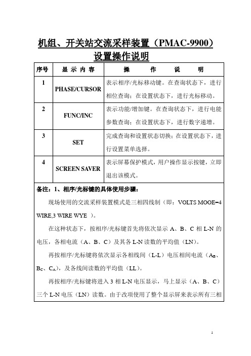
机组、开关站交流采样装置(PMAC-9900)设置操作说明
序号
显示内容
操作说明
1
PHASE/CURSOR
表示相序/光标移动键。在查询状态下,进行相位查询;在设置状态下,进行光标移动。
2
FUNC/INC
表示功能/增加键。在查询状态下,进行电能参数查询;在设置状态下,进行数字递增。
3
SET
完成查询和设置状态切换;在设置状态下,进行设置菜单选择。
再按相序/光标键将进入3相电流显示,马上出现3个电流读数。
2、功能/增加键的具体使用步骤:
a)功能或相显示消失:当显示三相电压和三相电流时,电能参数栏为空白;当有的电能参数值需占用整个显示屏去表示包含许多有效数据位或字符的电能参数名称和数值,这样,电压或电流数据栏为空白。
PMAC800系列产品使用手册

适用范围 重要电动机的综合保护 普通电动机的综合保护 普通电动机的电流保护 普通电动机的电流保护
SCT型号 SCT150 SCT200 SCT300 SCT400
电动机额定电流 150A及以下 200A及以下 300A及以下 400A及以下
PMAC系列产品主要特点
● PMAC系列智能电动机保护控制装置是针对低压电动机控制系统设计,超小外型尺寸,适用于GCK、GCS、GGD、 MNS等各种抽出式(包括1/4抽屉)、固定式及混合式的柜型安装。具有方便安装、布局合理、维护方便、节约电 缆、安全可靠等多种优点;
● 全面采用嵌入式 SOC(System On Chip 片上系统)设计、32 位 DSP(Digital Signal Processing 数字信号处理 技术和冗余现场总线技术,交流采样采用优化全波 FFT(Fast Fourier Transform 快速傅立叶变换)技术,软件 采用模块化、高抗干扰设计;
绝缘性能 绝缘电阻 工频耐压 冲击电压 耐湿热
各电气回路之间>20MΩ 各电气回路对地>20MΩ 各电气回路之间2KV/50Hz 1Min 各电气回路对地2KV/50Hz 1Min 各电气回路之间1.2/50μs, 5000V 各电气回路对地1.2/50μs, 5000V 遵循GB/T 2423.9-2001
PMAC系列智能电动机保护控制装置主要用于690V以下低 压电动机控制系统,对电动机的过负荷、短路、超长时间启 动、堵转、不平衡、接地、欠压、过压、工艺联锁等故障引 起的危害予以保护,并集合全面的三相电量测量/显示、数 字输入/输出与网络通讯于一身。每个装置具有多种综合电 力参数测量功能,既可单独作为电测仪表使用,亦可作为电 力综合自动化监控系统之前端,可实现测量、监视、保护、 控制等综合功能,通过其标准的RS-485通讯接口及双绞线网 络与监控系统通信,轻松实现数据的远方管理及“四遥”功 能。
GE Healthcare OEC 9900 Elite产品说明书

GE HealthcareDiscover the clear difference.All the special features you’ve come toassociate with OEC C-arms are residenton this latest generation C-arm, butwe’re taking the 9900 Elite to new heights.We’ve given you new features that canpositively impact your outcomes andenhance your productivity, while providingbetter return on your investment. Justwhat you’d expect from a recognizedmarket leader in mobile imagingtechnology for over 30 years.Come with us on a journey to discover thenew 9900 Elite’s superb imaging features.For over three decades,GE OEC has been amarket leader inmobile C-arm surgicalimaging. Now, theOEC 9900 Elite raisesthe mobile C-armstandard with PrecisionImaging Technologyusing DRM –DynamicRange Management.vascular productivity.Streamline eveStandard non-motorized C-arm offers superb mechanical design usingPremium 1k 2 High Resolution ImagingDigital Subtraction Roadmapping Iris Collimation Dual-Leaf CollimationSpine image withoutcollimator and Smart Window Image with Smart Window Metal Introduced Smart Metal EnabledNormal Digital Zoom Realtime Edge EnhancementImage I.Q.During live fl uoro, invisible AutoTraksampling window automatically moveswith the anatomy, ensuring superbimages no matter the position ofcollimation or centering.AutoTrakMoveable 18”Flat Panel Monitors• DICOM 3.0 internalinterface with Query andRetrieve standard.*• On-board DVD/CD Readand Write capability.• On-board Paper or HardCopy Film Option.Easy Archiving &DocumentationOEC ®9900 Elite....the cle • Twice the resolution.• Four times the information.21k 2 High ResolutionImaging • Standard High ResolutionBlack and White brightmonitors for superbfl uoroscopic viewing.• 700 Cd/m 2 maximumbrightness.• Optional right hand colormonitor for side-by-sideendoscopic and Black andWhite fl uoro images.• Advanced articulationmakes monitors visiblefrom all four sides.* DICOM options vary outside the United States.Physician Controlled X-ray Footswitch & Handswitch1k 2High ResolutionImaging Chain ear difference.C-arm Controls• Operation from eitherside of the system.Collision DetectionBumper forPatient Safetyon MD confi guration• High Resolution 9” (23 cm)or 12” (31 cm) Tri-ModeIntensifi er.- 9”, 6”, 4.5” (23, 15, 11 cm)- 12”, 9”, 6” (31, 23, 15 cm)15 kW Generator forPulsed CineBolus Chasing• 15 and 30 ppswith up to 150 mAfor high poweredpulse mode tostop motion orfreeze motion.• Generator isseparated fromthe X-ray tubeto provide highpower withoutincreasing X-raytube housingheat, improvingcooling effi ciency.High Power Rotating Anode X-ray Tube • High heat capacity X-ray tube with cooling system for long fl uoro on-times.• Fluoro• HLF High Level Fluoro• Digital Spot• Roadmap• Digital Subtraction• Low Dose ModePrecision Imaging...The DRM AdvantageProfi le Conventional OEC Image OEC 9900 Elite Image GeneralOrthopedicSpineVascularBolus ChaseCardiacvery procedure.working for you and your patients.training that can be shared with yourOur dedicated team of more than 200Field Service Engineers is made up offocused experts dedicated to servicingrst timerst time).Having engineers in all 50 states and a30-minute call-back commitment meanswe’re there for you when you need us.OEC systems maintained and running atpeak performance are better for you andperformance, choose the service offering*ts your needs. Our full-service,Primary Care coverage boasts a 97%preventative maintenance and offersconnectivity and unlimited parts andlabor features. Limited Service coverageis also available and provides technicalphone support, back-up on-site support* Service options may vary outside the United States.LR-990018-01©2008 General Electric Company – All rights reserved.General Electric Company reserves the right to make changes in specifi cations and features shown herein, or discontinuethe product described at any time without notice or obligation. Contact your GE Representative for the most current information.GE, GE Monogram and OEC 9900 Elite are trademarks of General Electric Company. GE OEC Medical Systems, Inc.Healthcare Re-imaginedGE is dedicated to helping you transformhealthcare delivery by driving criticalbreakthroughs in biology and technology. Our expertise in medical imaging and information technologies, medical diagnostics, patientmonitoring systems, drug discovery, andbiopharmaceutical manufacturing technologies is enabling healthcare professionals around the world discover new ways to predict, diagnose and treat disease earlier. We call this model of care “Early Health.” The goal: to help clinicians detect disease earlier, access more information and interveneearlier with more targeted treatments, so they can help their patients live their lives to the fullest. Re-think, Re-discover, Re-invent, Re-imagine.imagination at workg GE Healthcare,Surgery — Americas:Phone 801-328-9300Fax 801-328-4300GE Healthcare — Europe: Paris, FranceFax 33-1-30-70-94-35GE Healthcare — Asia:Tokyo, Japan —Fax: +81-452-85-5490Hong Kong —Fax: +852-2559-3588。
西格奈特9900转发器说明书
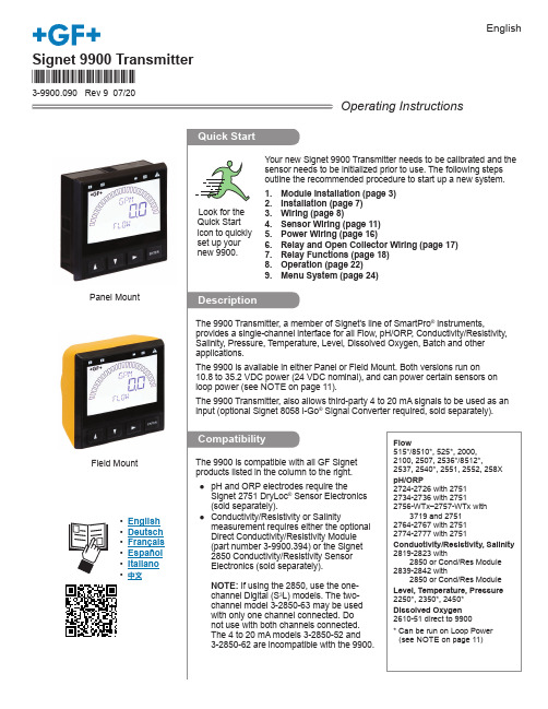
*3-9900.090*Signet 9900 Transmitter3-9900.090 Rev 9 07/20English® instruments,, Conductivity/Resistivity,® Signal Converter required, sold separately). Panel MountOperating InstructionsField MountFlow515*/8510*, 525*, 2000,2100, 2507, 2536*/8512*,2537, 2540*, 2551, 2552, 258XpH/ORP2724-2726 with 27512734-2736 with 27512756-WTx–2757-WTx with3719 and 27512764-2767 with 27512774-2777 with 2751Conductivity/Resistivity, Salinity2819-2823 with2850 or Cond/Res Module2839-2842 with2850 or Cond/Res ModuleLevel, Temperature, Pressure2250*, 2350*, 2450*Dissolved Oxygen2610-51 direct to 9900* Can be run on Loop Power(see NOTE on page 11)• English• Deutsch• Français• Español• Italiano• 中文29900 Transmitter39900 Transmitter3-9900.393 Relay Module 49900 Transmitter59900 TransmitterVerify 9900 TransmitterNOTE:T he 4 to 20 mA Output,Direct Conductivity, andBatch Modules share thesame installation site onthe 9900 base units. 69900 Transmitter79900 Transmitter89900 Transmitter99900 Transmitter109900 TransmitterTechnical Notes:• See corresponding product manuals for maximum cable length.• Maintain cable shield through cable splice.Technical Notes:• Wiring terminals on the 2537 are rated for 16 to 22 AWG wires.• The cable must be7 mm to 10 mm in diameter (0.275 in. to 0.394 in.) to seal2551 Technical Notes:• When the blue jumper illustrated here is placed over both pins, the 2551-XX-11 (Blind Magmeter) outputsan open collector frequencyTechnical Notes:• The cable length from the 8058 to the 9900 must not exceed 60 m (200 ft).• When using the 8058-2, connect the loop source to Channel 1 input ONLY .• See the 8058 manual for more information.Wiring for:Signet 8058 i-Go™4-20 mA to S L ConverterO u t p u t S 3LS L OutputDATA GND SHLD V+8058-1close-upBlackRed ShieldWhite 8058-19900 S 3L Inputs0 8058-23 2 16 5 47 8 9Loop1PWRN/C S L DATALoop2PWR+GF+ SIGNETclose-up8058-2DATA GND V+SHLD BLACKWHITE RED 9900 S 3L InputsTechnical Notes:• Use three conductor shielded cable for sensor cable splices up to 305 m (1000 ft) max.• Maintain cable shield through cable splice.• Route sensor cable away from AC power lines.• Connect the silver (shield) wire to earth ground in case of EMI noise interference.Technical Notes:• The 2850 has no SHIELD wire.• To work correctly with the 9900, the 2850 must be set for the custom cell constant or the actual probe cell constant and the 9900 set for a 1.0 cell constant.Wiring for:* 2551-XX-21, -41Display Magmeter2250235024502551*27512850Black Red ShieldWhite V+DATA GND SHLD 9900 S 3L InputsNOTE: The 2850 has no SHIELD wire.Keypad FunctionsThe four buttons of the keypad are used to navigate display modes according to the descriptions in this table. Notice that the function of each button may change depending on the display mode.3sEditInput EditSaves ChangesInput Edit Choices(Password may be required)or ororSelect another Menu ItemReturn to View Mode+2x+OrThis basic operating procedure repeats throughout the 9900 program:1. Press ENTER for 3 seconds to enter MENU mode.2. Press ► to move to the desired menu then press ENTER to select it. (Password may be required.)3. Press ▲ or ▼ to select the desired menu item for editing.4. Press ► to edit the value/selection.5. Press ENTER to store the new value/selection.6. Press ▲ or ▼ to select another menu item if desired. Repeat steps 3-5 as required.7. Press ▲+▼ to select a di ff erent menu to edit. Repeat steps 2-5 as required.8. When fi nished editing all menus, press ▲+▼ again to return to normal operation.The menu is constructed in a loop, so you can move forward and backward to select an item. After any item is saved (by pressing ENTER), the display will return to the previous menu.System Setup: Menu NavigationINPUT MenuThis is the normal display and does not time out.。
GE HEALTHCARE OEC 9900 Elite 说明书

GE HealthcareOEC® 9900 Elite Premium Digital Mobile C-arm Technical Data• 1k2high resolution imaging technology on a mobilesystem.• Featuring precision imaging Dynamic RangeManagement (DRM) for uncompromised image quality.• Flat panel monitors on an articulating arm allow viewing of images from anywhere in the room.• Simple user interface reduces procedure time toimprove efficiency.• Preset imaging profiles optimize I.Q. by enhancingfeatures of interest.• Remote service connectivity.X-ray System Generator• 60kHz high frequency• 15kW power• Up to 120kVp• Up to 75mA for radiographic film exposure • Continuous high level fluoro (HLF) up to 20mA• Digital spot up to 75mAX-ray Tube• Rotating anode X-ray tube• 0.3mm and 0.6mm focal spots• Anode heat capacity: 300,000 HU (per IEC 60613)• Anode cooling rate: 85,000 HU/min.• Housing heat capacity: 1,600,000 HU• Standard housing cooling 15,000 HU/min.• Passive housing cooling system: 22,500 HU/min. (Standard on 12 inch (31 cm)I.I. systems. Optional on 9 inch (23 cm) systems.Digital Image Rotation• Digitally adjusts image display• Automatic image update- Image rotation- Image reversal (side-to-side)- Image invert (top-to-bottom)• Image positioning without additional exposurePreView™ Collimator• On-screen collimator position indication • PreView™ iris collimator• PreView™ Tungsten rotatable double leaf collimator• Adjusts collimators without X-ray exposure Fluoro Mode• kVp range: 40 -120• mA range: 0.2 - 10 normal mode1.0 - 20 HLF (high level fluoro)• Auto and manual fluoro modes• AutoTrak™ ABS varies mA, kVp, camera gainPulsed Fluoro Mode• kVp range: 40 - 120• mA range: 0.2 - 10• Pulse rate: 1, 2, 4, 8• Pulse width: 25 or 50ms• AutoTrak™ ABS, mA, kVp, camera gain • Reduces X-ray dose to patient and operatorHigh Level Pulsed Fluoro• kVp range: 40 - 120• mA range: 1 - 40• Pulse rate: 1, 2, 4, 8• Pulse width: 25 or 50ms• AutoTrak™ ABS, mA, kVp, and camera gain Digital Spot Mode• kVp range: 40 - 120• mA range: Up to 75• Automatic exposure termination andautomatic image saveRadiographic Mode• mA range: up to 75• mAs range: up to 300• Computer controlled exposure time• Optional film cassette holder- 10” x 12” (24cm x 30cm) for 9” I.I.- 14” x 14” (35cm x 35cm) for 12” I.I.Video Imaging System9” Image Intensifier• Tri-mode 9”/6”/4.5” (23cm/15cm/11cm)image intensifier• Minimum central resolution (at themonitor):- 9” (23cm): 2.2 lp/mm- 6” (15cm): 3.0 lp/mm- 4.5” (11cm): 3.5 lp/mm• DQE: 65% (typical)12” Image Intensifier• Tri-mode 12”/9”/6” (31cm/23cm/15cm)image intensifier• Minimum central resolution (at monitor):- 12” (31cm): 1.6 lp/mm- 9” (23cm): 2.2 lp/mm- 6” (15cm): 2.6 lp/mm• DQE: 65% (typical)Precision imaging with Dynamic RangeManagement (DRM) enhances featuresof interest while attenuating backgroundnoise.• Preset Imaging Profiles- 9800- General- Orthopedic- Spine- Cardiac- Vascular- Bolus ChaseAutoTrak™Automatic Brightness Stabilization (ABS)• Automatically seeks the subject anatomyanywhere within the imaging field andselects the optimum imaging technique• Automatically adjusts to anatomical sizeand location• Provides uniform image quality throughoutentire image• Simplifies operationImage I.Q.• Smart Window- Dynamically senses the collimatorposition and automatically adjustsbrightness and contrast to producehigh image quality.• Smart Metal- Allows user to adjust automaticbrightness and contrast sensitivity levelsto metal- Provides optimum image quality evenwhen metal is introduced to the field• Tungsten Collimator- Denser collimator limits X-ray exposurearea- Reduces scatter radiation- Improves image detailVideo Camera• High resolution 1k x 1k CCD camera• Full frame capture• Motorized rotation• On-screen orientation indicator (real-timefeedback without fluoro)• Left-right image reversal• Top-bottom image invertVideo Display• Dual 18” (46cm) displayanti-glare, LCD flat panel monitorsmounted on an articulating arm- 22” horizontal travel- 7° up/10° down- Monitors viewable from all four sides ofworkstation- Horizontal and vertical viewing angle170°• 700 CD/M2 maximum brightness• Touch screen system control• 1280 x 1024 high resolution monitors• Ambient room-light compensation• Integrated color monitor for display ofVGA, DVI, DVI-D, S-VHS, and SDI-SDformats (optional)ConfigurationsGSP Platform• 1k x 1k x 16 bit image processing• Preset Imaging Profiles- 9800- General- Orthopedic- Spine• Noise filter with on-screen indicator• Minimal difference spatio-temporalnoise filter (MDST)• Real time dynamic range management(DRM)• Automatic digital brightness and contrastcontrol• Manual digital brightness and contrastcontrol• Negate mode• Save and auto-save feature• Swap and auto-swap feature• Patient information- Examination list- Customized patient information• Customize functions- Workstation set-up- Mainframe set-up- Patient information set-up- Date/time set-up- DICOM interface set-up• Last image hold• 63 image storage• CD/DVD burner with DICOM viewer for displaying images on PC platforms- 512 x 512 or 1k x 1k• Integrated DICOM interface (store, print, worklist, and query/retrieve)• HIPAA SecureView®- Password protection- Blank screen function- Delete allESP PlatformIncludes all the GSP features and:• 1000 image storage• Zoom and roam function• Image annotation• Measurement softwareESP Platform with 15fps Digital Disk Includes all the ESP features and:• 15fps Dynamic digital disk (60 Hz) 12fps (50 Hz)- Recording/playback rate: 1, 2, 4, 8, 15fps(60 Hz) 12fps (50 Hz)- Automatic image playback capability- Frame-by-frame review- Recording time: 10 minutes @ 15fps (60Hz) 12 fps (50 Hz)PMCare PlatformIncludes all the ESP features and:• Real-time subtraction• Digital subtraction (DSA) angio• Peak opacification• 8fps Dynamic digital disk- Recording/playback rate: 1, 2, 4, 8fps- Recording time: 5 minutes @ 8fps- Automatic image playback- Frame-by-frame reviewBasic Vascular PlatformIncludes all the PMCare features and:• Vascular preset imaging profile• Roadmapping• Re-registration• Variable landmarking• Mask save/recallVascular MTS PlatformIncludes all the Basic Vascular features plus Motion Tolerant Subtraction (MTS) and:• Bolus chase preset imaging profile• Digital cine pulse mode- 30 pulses/sec 60 Hz (25 pulses/sec 50 Hz)- Up to 150mA- 10ms pulse width• 30fps Dynamic digital disk 60 Hz (25pulses/sec, 50 Hz)- Recording/playback rate: 1, 2, 4, 8, 15,30fps 60 Hz (1, 2, 4, 8, 12, 25, 50 Hz)- Recording time: 10 minutes @ 30fps 60 Hz(time depends on record frame rate)(25 fps, 50 Hz)Cardiac Platform withInterventional Vascular CapabilityIncludes all the Vascular MTS features and:• Cardiac preset imaging profile• Super “C” configuration (9”/23cm I.I. only)• Single leaf curved collimator• Three pedal footswitchAdditional FeaturesHardcopy Options• Integrated film/paper printer- No film developing required- 8” x 10” (20.3 cm x 25.5 cm) laser qualityfilm/paper- Multi-format, 1, 2, 4 on 1- Multi-copy capability• Thermal printers• Integrated DICOM interface (storageclass/print class/query work-list)*User Interface• Entire system is computer controlled andsoftware upgradeable• Touchscreen control simplifies operation• Automated system operation requiresminimum operator interface• Multi-functional controls- Footswitch- IR remote (optional)- Hand-held control• Simplified keyboard with integratedtouchpad• Multi-purpose image directory- Retrieve and review images- Compose hardcopy films- Copy images• X-ray dose summaryUninterruptible Power•Orderly shutdownElectrical•Input power (60 Hz or 50 Hz)9900 Elite- 120V @ 12 A- 200V, 220V, 230V, 240V @ 10 AAvailable Languages for Operator Manuals• EnglishRegulatory Compliance• U.S. 21 CFR Subchapter J• NFPA 99• UL 60601-1 (CSA/NRTL)• IEC60601-1 (plus relevant Collateral andParticular Standards)Standard C 9” (23cm) I.I.Standard C 12” (31cm) I.I.Super C 9” (23cm) I.I.Motorized C-arm 9” (23cm) I.I.OEC ® 9900 Elite Configuration Options The OEC 9900 Elite is available in a number of configurations, allowing you to select the product features that best meet yourclinical needs:Motorized C-arm 12” (31cm) I.I.Orthopedics, General Surgery and Pain Management 9900 GSP 9900 ESP9900 PMCare 8 F/S Digital Subtraction 9900 ESP 15 F/S (12 F/S @ 50 Hz)• For orthopedics, general surgery, GI, pain management and other general applications.Endovascular9900 Basic vascular 8 F/S9900 Vascular MTS 30 F/S (25 F/S @ 50 Hz)• For vascular surgery and interventional vascular applications.• 12/9/6” (31/23/15 cm) tri-mode image intensifier: A larger field of view than our standard 9/6/4.5” (23/15/10 cm) image intensifier, for manyvascular applications or wherever a larger field of view is required.Cardiac Surgery and Mobile Cardiac Cath lab/EP lab 9900 Cardiac 30 F/S (25 F/S @ 50 Hz)• For complex coronary, peripheral or abdominal angiography.• Super-C design: Larger than our standard C, the Super C design provides greater clearance and greater range of overscan for the oblique angulations required inboth cardiac and spine work (9” (23 cm) I.I. only).9900 MD C-arm• 9°/sec. Lateral Motorized Rotation.• 9” (23 cm) I.I., 12” (31 cm) I.I.• RUI (Remote User Interface - Table Side Control Panel - All 9900 Mainframe Controls. - Image Review Functions.- C-arm Motion Joystick Control. - Motorized Vertical Lift.• Contact/Collision Detection.• C-arm Angle Display - re altime and saved images.• Enhanced X-ray tube housing cooling system.Integrated Surgical Navigation• Realtime electro magnetic tracking of instruments on fluoroscopic images.• Available on all configurations except Cardiac, MD and 12 inch.• Ability to track two instruments simultaneously.*DICOM options vary outside the United States.System configuration optionsPhysical SpecificationsWorkstationLR-990014-02©2007 General Electric Company – All rights reserved.General Electric Company reserves the right to make changes in specifications and features shown herein, or discontinue the product described at any time without notice or obligation. Contact your GE Representative for the most current information.GE, GE Monogram and OEC 9900 Elite are trademarks of General Electric Company. GE OEC Medical Systems, Inc., doing business as GE Healthcare.Healthcare Re-imaginedGE is dedicated to helping you transform healthcare delivery by driving criticalbreakthroughs in biology and technology. Our expertise in medical imaging and information technologies, medical diagnostics, patient monitoring systems, drug discovery, andbiopharmaceutical manufacturing technologies is enabling healthcare professionals around the world discover new ways to predict, diagnose and treat disease earlier. We call this model of care “Early Health.” The goal: to help clinicians detect disease earlier, access more information and intervene earlier with more targeted treatments, so they can help their patients live their lives to the fullest. Re-think, Re-discover, Re-invent, Re-imagine.GE Healthcare384 Wright Brothers Drive Salt Lake City, Utah 84116USAimagination at workgGE Healthcare,Surgery — Americas: Phone 801-328-9300 Fax 801-328-4300GE Healthcare — Europe: Paris, FranceFax 33-1-30-70-94-35GE Healthcare — Asia:Tokyo, Japan —Fax: +81-452-85-5490Hong Kong —Fax: +852-2559-3588。
9900操作手册
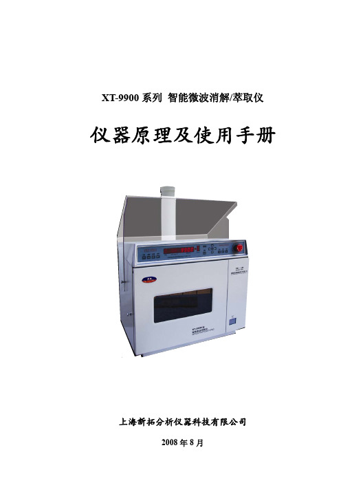
XT-9900系列智能微波消解/萃取仪仪器原理及使用手册上海新拓分析仪器科技有限公司2008年8月为保证仪器消解过程安全、顺利进行,请务必在使用前仔细、认真地阅读本操作手册,并严格按照本操作手册中的操作规程进行操作。
操作过程中应特别注意加“●”的内容,以免造成不必要的损失和伤害。
凡不按本规程操作,发生事故而造成设备和人员伤害的,本公司不予负责。
目录第一部分微波消解原理、仪器组成及维护 (1)1. 前言 (1)2. 仪器原理和特点 (1)2.1 微波消解基本原理 (1)2.2 XT-9900型智能微波消解/萃取仪的控压原理 (2)2.3 XT-9900型智能微波消解/萃取仪的性能特点及技术指标 (3)3. 仪器结构、安装、使用与维护 (4)3.1 仪器面板正面及背面标示 (4)3.2 仪器安装注意事项 (5)3.3 消解仪的安全使用准则 (5)3.4 消解仪的维护保养 (6)4. 消解罐结构、使用与维护 (6)4.1 消解罐结构 (6)4.2 消解罐的安全使用准则 (7)4.3 消解罐的维护保养 (7)5. 本仪器的安保措施 (8)6. 主要故障及其排除方法 (9)第二部分仪器操作规程 (12)1. 准备工作 (12)1.1 工具的检查与作用 (12)1.2 消解仪检查 (12)1.3 消解罐的检查和组装 (12)2. 样品消解操作步骤 (13)2.1 样品准备 (13)2.2 消解罐的组装 (13)2.3 加热时间、压力的选择 (14)2.4 关于两个以上消解罐同时加热的注意事项 (14)2.5 仪器参数设置及操作步骤 (15)2.6 仪器微波消解注意事项 (18)2.7 消解罐的冷却、开启及试液转移 (18)3. 样品开始消解之前的几个问题 (19)3.1溶样杯的几种洗涤方法 (19)3.2 样品称量、溶样酸种类及酸量参考 (19)3.3 微波消解前,样品的加热预处理 (20)第三部分微波消解相关参考资料 (21)1. 建立密闭微波消解方法的步骤 (21)2. 密闭微波消解应用中酸的选择 (21)3 未知样品的试验 (24)3.1 有机物样品的试验方法 (24)3.2 无机物样品的试验方法 (24)3.3 含有机物基质的无机物样品的试验方法 (24)第一部分微波消解原理、仪器组成及维护1. 前言感谢您使用上海新拓分析仪器科技有限公司最新研制的XT-9900型智能微波消解/萃取仪!在现代分析化学中,与人体健康、环境保护、材料组分、矿物含量、食品安全等密切相关的元素分析越来越受到人们的关注和重视。
欧安199099产品说明书

Eaton 199099Eaton Moeller® series Rapid Link - Reversing starter, 6.6 A,Sensor input 2, AS-Interface®, S-7.4 for 31 modules, HAN Q4/2,with manual override switchGeneral specificationsEaton Moeller® series Rapid LinkReversing starter199099120 mm270 mm220 mm1.8 kg IEC/EN 60947-4-2CCCUL approvalCERoHSUL 60947-4-2Assigned motor rating: for normal internally and externally ventilated 4 pole, three-phase asynchronous motors with 1500 rpm at 50 Hz or 1800 min at 60 Hz RAMO5-W200A31-412RS1Product Name Catalog NumberProduct Length/Depth Product Height Product Width Product Weight CertificationsCatalog Notes Model CodeIs the panel builder's responsibility. The specifications for the switchgear must be observed.3 kW6.6 A (at 150 % Overload)480 V AC, 3-phase400 V AC, 3-phase10000 A0 VMeets the product standard's requirements.Is the panel builder's responsibility. The specifications for the switchgear must be observed.Does not apply, since the entire switchgear needs to be evaluated.0 kW2.238 kWMeets the product standard's requirements.0 V-40 °CThermo-clickTwo sensor inputs through M12 sockets (max. 150 mA) for quick stop and interlocked manual operationKey switch position OFF/RESET Generation change from RA-MO to RAMO 4.0Generation Change RASP4 to RASP5Generation change RAMO4 to RAMO5Generation change from RA-SP to RASP 4.0Configuration to Rockwell PLC for Rapid LinkGeneration Change RA-SP to RASP5Rapid Link 5 - brochureDA-SW-drivesConnect - InstallationshilfeDA-SW-Driver DX-CBL-PC-3M0DA-SW-USB Driver PC Cable DX-CBL-PC-1M5DA-SW-drivesConnect - installation helpDA-SW-drivesConnectDA-SW-USB Driver DX-COM-STICK3-KITMaterial handling applications - airports, warehouses and intra-logistics ETN.RAMO5-W200A31-412RS1.edzIL034084ZUramo5_v11.stpramo5_v11.dwgDA-DC-00004184.pdfDA-DC-00004525.pdfDA-DC-00003964.pdfDA-DC-00004523.pdfeaton-bus-adapter-rapidlink-speed-controller-dimensions-002.eps eaton-bus-adapter-rapidlink-reversing-starter-dimensions-003.eps eaton-bus-adapter-rapidlink-reversing-starter-dimensions-002.eps eaton-bus-adapter-rapidlink-speed-controller-dimensions-003.eps10.11 Short-circuit ratingRated operational power at AC-3, 380/400 V, 50 HzInput currentRated operational voltageRated conditional short-circuit current, type 1, 480 Y/277 V Rated control supply voltage (Us) at AC, 50 Hz - min10.4 Clearances and creepage distances10.12 Electromagnetic compatibility10.2.5 LiftingRated power at 575 V, 60 Hz, 3-phaseRated power at 460 V, 60 Hz, 3-phase10.2.3.1 Verification of thermal stability of enclosures Rated control supply voltage (Us) at DC - minAmbient storage temperature - minFitted with:Applikasjonsmerknader BrosjyrereCAD model Installeringsinstruksjoner mCAD model SertifiseringsrapporterTegningerElectronic motor protectionKey switch position HANDManual override switchKey switch position AUTOThermistor monitoring PTCShort-circuit releaseOverload cycleAC-53aNumber of pilot lightsRated control supply voltage (Us) at AC, 50 Hz - max0 VSystem configuration typeAC voltagePhase-earthed AC supply systems are not permitted. Center-point earthed star network (TN-S network)10.8 Connections for external conductorsIs the panel builder's responsibility.Coordination class (IEC 60947-4-3)Class 1Rated conditional short-circuit current, type 1, 600 Y/347 V 0 ARated conditional short-circuit current (Iq)10 kAAmbient operating temperature - max55 °CRated operational power at AC-3, 220/230 V, 50 Hz0 kWClimatic proofingIn accordance with IEC/EN 50178< 95 %, no condensationFeaturesParameterization: FieldbusDiagnostics and reset on device and via AS-Interface Parameterization: drivesConnectParameterization: drivesConnect mobile (App) Parameterization: KeypadLifespan, electrical10,000,000 Operations (at AC-3)Number of command positions2Electrical connection type of main circuitPlug-in connectionElectrical connection type for auxiliary- and control-current circuit Plug-in connectionRated control supply voltage (Us) at DC - max0 V10.9.3 Impulse withstand voltageIs the panel builder's responsibility.Ambient operating temperature - min-10 °C10.6 Incorporation of switching devices and componentsDoes not apply, since the entire switchgear needs to be evaluated.Current limitation0.3 - 6.6 A, motor, main circuitAdjustable, motor, main circuitCable length10 m, Radio interference level, maximum motor cable length10.5 Protection against electric shockDoes not apply, since the entire switchgear needs to be evaluated.Mounting positionVerticalMains switch-on frequencyMaximum of one time every 60 secondsClassCLASS 10 A10.13 Mechanical functionThe device meets the requirements, provided the information in the instruction leaflet (IL) is observed.10.2.6 Mechanical impactDoes not apply, since the entire switchgear needs to be evaluated.10.9.4 Testing of enclosures made of insulating materialIs the panel builder's responsibility.10.3 Degree of protection of assembliesDoes not apply, since the entire switchgear needs to be evaluated.Electromagnetic compatibilityClass AVoltage typeDCProduct categoryMotor starterOverload release current setting - min0.3 ARated control voltage (Uc)24 V DC (-15 %/+20 %, external via AS-Interface® plug)Rated operational current (Ie)6.6 AAssigned motor power at 460/480 V, 60 Hz, 3-phase3 HPRated frequency - min47 HzNumber of auxiliary contacts (normally closed contacts)Rated conditional short-circuit current (Iq), type 2, 380 V, 400 V, 415 V0 APower consumption8 W10.2.3.2 Verification of resistance of insulating materials to normal heatMeets the product standard's requirements.10.2.3.3 Resist. of insul. mat. to abnormal heat/fire by internal elect. effectsMeets the product standard's requirements.On-delay20 - 35 msLifespan, mechanical10,000,000 Operations (at AC-3)Rated operational current (Ie) at 150% overload6.6 AProtocolAS-Interface profile cable: S-7.4 for 31 modulesASIOverload release current setting - max6.6 A10.9.2 Power-frequency electric strengthIs the panel builder's responsibility.Overvoltage categoryIIIDegree of protectionIP65NEMA 12Rated frequency - max63 HzVibrationResistance: According to IEC/EN 60068-2-6Resistance: 57 Hz, Amplitude transition frequency on accelerationResistance: 6 Hz, Amplitude 0.15 mmResistance: 10 - 150 Hz, Oscillation frequencyRated operational power at 380/400 V, 50 Hz - max3 kWAmbient storage temperature - max70 °CShort-circuit protection (external output circuits)Type 1 coordination via the power bus' feeder unit, Main circuitRated control supply voltage (Us) at AC, 60 Hz - min0 V10.7 Internal electrical circuits and connectionsIs the panel builder's responsibility.Rated impulse withstand voltage (Uimp)4000 VConnectionConnections pluggable in power sectionOff-delay20 - 35 ms10.10 Temperature riseThe panel builder is responsible for the temperature rise calculation. Eaton will provide heat dissipation data for the devices.FunctionsExternal reset possibleTemperature compensated overload protectionOutput frequency50/60 HzMains voltage tolerance380 - 480 V (-15 %/+10 %, at 50/60 Hz)Rated conditional short-circuit current (Iq), type 2, 230 V0 AInterfacesNumber of slave addresses: 31 (AS-Interface®) Specification: S-7.4 (AS-Interface®)Max. total power consumption from AS-Interface® power supply unit (30 V): 190 mATypeReversing starter10.2.2 Corrosion resistanceMeets the product standard's requirements.Supply frequency50/60 Hz, fLN, Main circuit10.2.4 Resistance to ultra-violet (UV) radiationMeets the product standard's requirements.10.2.7 InscriptionsMeets the product standard's requirements.Rated control supply voltage (Us) at AC, 60 Hz - max0 VRated operational current (Ie) at AC-3, 380 V, 400 V, 415 V6.6 ARated operational power at 380/400 V, 50 Hz - min0.09 kWModelReversing starterNumber of auxiliary contacts (normally open contacts)Shock resistance15 g, Mechanical, According to IEC/EN 60068-2-27, 11 ms, Half-sinusoidal shock 11 ms, 1000 shocks per shaftAltitudeMax. 2000 mAbove 1000 m with 1 % performance reduction per 100 m Max. 1000 mEaton Corporation plc Eaton House30 Pembroke Road Dublin 4, Ireland © 2023 Eaton. Med enerett. Eaton is a registered trademark.All other trademarks areproperty of their respectiveowners./socialmedia。
9900说明书1
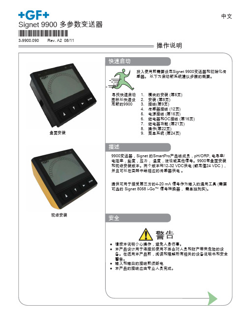
现场安装
安全
警告
● 请按本说明小心操作,避免人身伤害。 ● 本产品设计用于连接如使用不当会对人员和财产带来危险的设
备。在适用本产品前,阅读和理解所有相关的设备说明书和安全 警告。 ● 输入和输出的接线前须断电 ● 本产品的接线应由专业人员完成。
目录
Georg Fischer Signet 专业流体测量
描述
9900变送器,Signet 的SmartPro产品线成员,pH/ORP, 电导率/ 电阻率,盐度,压力, 温度,液位或其他信号。9900有盘面安装 和现场安装版本。两个版本均12-32 VDC供电 (额定值24 VDC ), 并且可以在回路中给相应的传感器供电 。
提供可用于接受第三方的4-20 mA 信号作为输入的通用工具 (需要 可选的 Signet 8058 i-Go™ 信号转换器, 需单独购买)。
可插拔模块 ................................................................................6 继电器模块 ................................................................................6 电导/电阻率模块 .......................................................................7 H COMM 模块 ..........................................................................7 安装 ................................................................................................8 接线 ................................................................................................9 信号类型:频率 ......................................................................10 信号类型:数字 (S3L) .............................................................10 信号类型:4-20mA .................................................................11 Terminal Identification ............................................................11 传感器接线 ..............................................................................12 电源接线 .................................................................................15 继电器和集电极开路输出接线 .................................................16 继电器和集电极开路输出 ........................................................17 继电器功能....................................................................................21 操作 ..............................................................................................22 菜单系统 .......................................................................................24 系统设定菜单 ..........................................................................24 常用菜单 .......................................................................................26 电流回路菜单 ..........................................................................26 继电器菜单 ..............................................................................27 选项菜单 .................................................................................29 传感器菜单....................................................................................30 流量 ........................................................................................30 pH ...........................................................................................32 ORP ........................................................................................34 电导/电阻率菜单 .....................................................................35 压力 ........................................................................................37 液位/体积量 .............................................................................38 温度 ........................................................................................40 4-20mA ...................................................................................41 盐度 ........................................................................................43 故障诊断 .......................................................................................45 附录 ..............................................................................................46 平均时间 .................................................................................46 算法模式电流回路输出 ............................................................47 自定义测量 ..............................................................................48 标定步骤- pH ..........................................................................52 标定步骤- ORP .......................................................................55 标定步骤-电导率/电阻率 .........................................................56 标定步骤-流量 .........................................................................57 标定错误信息 ..........................................................................58 USP(美国药典)限定 ................................................................59 规格 ..............................................................................................60 订货信息 .......................................................................................64
网络电力仪表品种及选型方法
网络电力仪表 品种及选型方法上海安科瑞电气股份有限公司 1、概述网络电力仪表是针对电力系统、工矿企业、公共设施、智能大厦的电力监控需求而设计 的。
它能测量所有的常用电力参数,如三相电流、电压,有功、无功功率,电度、谐波等。
由于该电力仪表还具备完善的通信联网功能, 所以我们称之为网络电力仪表。
它非常适合于 实时电力监控系统。
该表具有很高的性能价格比, 可以直接取代常规电力变送器及测量仪表。
作为一种先进 的智能化、数字化的前端采集元件,该系列网络仪表已广泛应用于各种控制系统、SCADA 系 统和能源管理系统中。
2、国内主要品牌及型号国内生产网络电力仪表厂家、 型号品牌繁多, 主要常见的产品有: 雅达 YD2200、 YD2100、 YD2110、YD2050、YD2030、YD2020 智能电力检测控制仪表;溯高美 DIRIS A20、A40,DIRIS CMV2;上海二工 PD800H、PD800H-M13、PD800H-M14、PD800H-X13、PD800H-X14;保定华异 特 HYT-DN 多功能电测仪;珠海派诺 PMAC9900E 综合电力测控仪、PMAC720 多功能电力监控 仪、PMAC720D-H-V、PMAC720C-H-V、PMAC720C-HM-V、PMAC720C-H-AI-V、PMAC720D-H-AO-V、 PMAC9900E-NR-V、PMAC9900E-2R-V、PMAC9900E-2R-D-V;江阴科达 KDY-1M4S2、KDY-1M7S2、 KDY-1M9S2;华通测控 PDM-803HE、PDM-803HA、PDM-803H;上海安科瑞 ACR10E、ACR10EL、 ACR10EFL、ACR100E、ACR110E、ACR120E、ACR120EL、ACR120EFL、ACR200K、ACR200ILH、 ACR200ULH、ACR200UILH、ACR200E、ACR210E、ACR220E、ACR220EL、ACR220EFL、ACR300E、 ACR310E、ACR320E、ACR320EL、ACR320ELH、ACR320EFLH、ACR330ELH、ACR410E、ACR420E、 ACR430EGH、ACR450EGH,四象限电能,复费率电能,正负零序分量、电流 K 系数,电压波峰 系数, 电话波形因子, 事件记录, SOE 谐波分量; 斯菲尔 PD194Z-2SY、 PD194Z-9SY、 PD194Z-2S4、 PD194Z-9S4 、 PD194Z-9S9 、 PD194Z-9S9A 、 PD194Z-2S7 、 PD194Z-2S7A 、 PD194Z-2S4K 、 PD194Z-1S5、 PD194E-2S4、 PD194E-9S4、 PD194E-9S7、 PD194E-9S9、 PD194E-9F2、 PD194E-9F2A、 PD194E-9F3、PA2000-2、PA2000-3;珠海大唐 DTM600、DTM601、DTM602,配电综合测控仪; 亚特尔 MDM3000 综合电力测控仪 DNS/DNXS/DNS(X)9000 电能表;因泰莱 IDM30H、IDM30C、 IDM30HC; 爱博精电 ACUVIM-DX、 ACUVIM-EX、 ACUVIMII、 ACUVIM-400、 ACUVIM-AL、 ACUVIM-BL; 盛善 SD96-EZ1、 SD96-EZ2、 SD96-EZ3、 SD96-EY3、 SD42-EZ2、 SD42-EZ3、 SD42-EY3、 SD96-EG3、 SD42-ES1、SD42-EG1、SD96-EG1、SD96-ES3、SD42-ES3;深圳中电电力 PMC-530A、PMC-5330、 PMC-5350、 PMC-510A、 PM700MG、 PM700PMG、 PM710MG、 PM800、 PM810、 PM820、 PM850、 ION7550、ION7650、ION7300、ION7330、ION7350、ION6200;施耐德 PM810、PM820、PM850、PM870、 PM700、PM700P、PM710、PM200、PM200P、PM210 电力参数测量仪;高力特 GGE ET6000 电力 监控单元;苏州万龙 ST400M1、ST400M2、ST400M3、ST400M5、ST400H1、ST400H3、ST400H5、 ST400III1、ST400III2、ST400III5 智能型电力测控仪表;合肥友恒 YH2010A、YH2010B 多 功能网络电力仪表; 东瑞 PD204Z-2SY、 PD204Z-2S4、 PD204Z-2S4K、 PD204Z-2S4、 PD204Z -9S4、PD204Z-2S7、PD204Z-9S7、PD204Z-9S9;美国电气控制 QP650、QP550、QP450、 QP451、QP452、QP300、QP301、QP302;广州汉光 PD866E-718、PD866E-730、PD866E-518、 PD866E-545、PD866E-560,多功能电力仪表;合肥英特 YTWPI-3(4)、YTZJ-1、YTZJ-1A 智能 型电力监控仪;西安超龙 CHR801、CHR803、CHR804 电力测控仪;陕西和创 HD2000、HD2200、 HD2300 智能电力监控仪;北京易艾斯德(ESDTEK)EM600A、EM600B、EM600C、EM600D 智能 电量仪表,EM600E、EM600F、EM600G、EM600H、EM600I、EM600M、EM600N、EM600P,电力监 控装置 EM900A、EM900B、EM900C、EM900D、EM900E;上海宾瑞 BRN-D302-AS、BRN-D303-AS、 E203-AS、E202-AS;鑫龙自动化 DMX300B、DMX300C、DMX301、DMX302、DMX303、DMX306、 DMX308;上海华健 LCM-100、LCM-120、LCM-101、LCM-102、LCM-122、LCM-123、LCM-103、 LCM-124、LCM-105、LCM-500、LCM-501、LCM-503、LCM-504、LCM-505 智能监测装置;昆明 阳光 PM98E80、PM98E83M、PM98E83E、PM98E81E、PM98E81V 交流电参数测量表,PM98E83C、 PM98E83R 、 PM98E83R 、 PM98E83A ; 新 未 来 NFC-2000 配 电 智 能 监 控 终 端 ; 陕 西 科 飞 KFDJ-6350-II、KFDJ-6342-II、KFDJ-6351-I 智能电力监测仪等等。
PMAC9900产品说明书

界面友好 该功能在用户配置显示单元时有效 用户可 以方便的通过显示单元查询数据或者是进 行现场编程
运行方便 全部的测量值 整定值都可以通过本地或者 是通讯口存取
信息透明 全部的测量数据都采用一次侧数值显示
完善的数据查询功能
PMAC®9900 提供两种方式供用户查询实时 监测的数据量
显示 通过独立单元的显示模块 用户可以任意查 询所关心的数据 并且可以进行现场的编 程 调整仪表的工作参数
功率因数计算
PMAC®9900 可以计算出全相限的功角值 用户可以查询到当前功角的超前滞后关系 与功率数据一样 接线的对应关系以及 CT 同名端关系都会影响到功率因数的实际计 算值
频率测量
PMAC®9900 工作于不同系统模式时 频率 测量的采集通道时不相同的 在三角形模式 下 PMAC®9900 是通过 C 相电压通道测量 频率 其它模式下 PMAC®9900 是通过 A 向电压通道测量频率的
显示单元
三相四线星形 三相三线星形和 DEMO 模式
序
电压
相序
电流
号
1 A 相电压
A
A 相电流
2 B 相电压
B
B 相电流
3 C 相电压
C
C 相电流
4 平均相电压 LN 平均相电流
5 AB 线电压 AB A 相电流
6 BC 线电压 BC B 相电流
7 CA 线电压 CA C 相电流
8 平均线电压 LL 平均相电流
适用于电压等级超过 600V 线 系统 适用于三相三角形系统 此时仪表电压模式设置为 3 WYE 仪表 PT USE?为 YES 设置 PT PRIMARY 参 数和 PT SECONDARY 参数 Ixx 表示电流端子 Vx 表示电压端子
RFX9900 车载音箱说明书

INSTRUCTION MANUALRFX9900l●Capacitive Touch Control Panell●7-line Dot Matrix Displayl●SiriusXM-Ready TMl●FM/AM Stereo Radiol●HDMI Outputl●CD-DVD Changerl●USB&SD Audio/Video Playl●DMD(Digital Music Device)Playl●Punch EQl●BluetoothCONTENTSCONTENTS (1)CONTROL PANEL (WIRE REMOTE) ILLUSTRATION (2)WIRE DIAGRAM (3)INSTALLATION (4)BASIC OPERATION (6)RADIO OPERATION (7)SIRIUSXM OPERATION (8)USB/SD OPERATION (10)DMD OPERATION (11)AUX IN OPERATION (11)CDC/DVDC OPERATION (12)IR REMOTE CONTROL (13)SPECIFICATIONS (14)TROUBLESHOOTING (15)CONTROL P ANEL I LLUSTRATION1. POWER2. SEEK-3. BAND/SUB4. DISP5. SEEK+6. MODE7. VOLUME SEL/ENT8. LCD Display9. SCAN/MENU10. AS/PS11. Preset 1/ PAUSE-PLAY12. Preset 2/RPT13. Preset 3/INT14. Preset 4/RDM15. Preset 516. Preset 617. IR ReceiverWIRE D IAGRAMFUSE REPLACEMENT:If the fuse blows, check the power connection and replace the fuse. If the fuse blows again after the replacement, there may be an internal malfunction. In this case, contact your nearest repair center.Warning:Only replace fuse with the same type and rating. Use of a different type or rating may cause serious damage/safety concerns.INSTALLATIONPRECAUTIONSChoose the mounting location carefully so that the unit will not impair the safe operation of the vehicle, or interfere with the driver.Avoid installing the unit where it would be subject to high temperature, such as from direct sunlight or hot air from the heater, or where it would be subject to dust, dirt or excessive vibration.Use only the supplied mounting hardware for a safe and secure installation.To support the unit1.UNIT2.DASH B OARO3.HEX N UT M54.LOCK W ASHER5.PLAIN W ASHER6.MARINE B ODY7.REAR S UPPORT S TRAP8.TAPPING S CREW9.M5x15 H EY B OLTBASIC O PERATIONNOTE:Short press:Press less than 2 seconds.Long press:Press and hold more than 2 seconds.POWER Button (1)l●Power ON/OFFShort press the button to turn on/off the unit.VOLUME PUSH SEL (7)l●Volume ControlRotate the knob to control the volume 0-40.l●Select VOL/BAS/TRE/BAL/FAD/DSPShort press to select VOL/BAS/TRE/BAL/FAD/DSP (FLAT/CLASSIC/POP/ROCK) then rotates the knob to adjust desired setting. Press the knob again to select desired functions. Unit will return to normal previous display if left without any key be pressed for 5 seconds.l●Select AREA/ILLUMLong press to select AREA (USA/EUR)/ILLUM (0-10), then rotate the knob to adjust desired setting. Press the knob again to select desired functions. Unit will return to normal previous display if left untouched for 5 seconds.l●AREABy pressing the knob again, the unit will be in Radio AREA selection mode. Rotate the knob to choose USA or EUR (Europe).l●ILLUMYou can adjust the Illumination brightness in this mode, there are 10 levels you can select, when you find the desired brightness by rotating the knob, press the knob will save the setting.MODE (6)l●MODE SelectionShort press MODE button to choose desired listening mode, RADIO(FM/AM)/SiriusXM/USB1/USB2 (SD)/AUX/CDC (DVDC)/BluetoothDISP (4)l●System Time SettingLong press this button until hour icon begins to flash, rotate volume knob to adjust hour indication. And then short press until minute icon begins to flash, rotate volume knob to adjust minute indication. The system will save current time and exit time setting if user press the key again or there is no action within 5 seconds.BAND/SUB (3)l●Band SwitchShort Press this key to change Band between AM-FM1-FM2l●Subwoofer ON/OFFLong press this key to choose between Subwoofer ON and OFF.RADIO O PERATIONMODE (6)l●MODE SelectionShort press MODE button to select radio mode.BAND/SUB (3)l●Band SelectionIn radio mode, short press BAND button to locate the desired band. The reception band will change in the following order:FM1 - FM2 - AMSEEK+ (2)/SEEK- (5)l●Automatic SeekShort press to automatically seek the higher/lower radio station.l●Manual tuningLong press to enter manual tuning mode, then short press to seek the higher/lower frequency. The manual tuning mode will exit automatically if there is no action within 5 seconds.PRESET 1-6 (11/12/13/14/15/16)l●Store Preset StationLong press a PRESET button, the current station will be stored, and theCorresponding preset number will appear in the display. The PRESET buttons can be used to store 6 stations in each band (FM1, FM2, and AM) for convenient access to your favorite stations.l●Recall Preset StationTo recall a station, select a band (if needed).Short press a Preset button and the unit will turn to the corresponding stored station.SCAN/MENU (9)l●All Station ScanningPress SCAN button to scan all stations. The unit will keep on scanning every 5 seconds until you press the SCAN button again to stop scan function.AS.PS (10)l●Automatically StoreLong press this button for more than 2 seconds, and the unit will automatically scan and store the strongest stations in the FM/AM band. To stop this function before the automatic storing is complete, shortly press this button again.l●Preset Station ScanningLong press this button to scan preset station. The unit will keep on scanning every 5 seconds until you press the SCAN button again to stop scan function.SiriusXM O PERATIONEverything w orth l istening t o i s o n S iriusXM, g etting o ver 130 c hannels, i ncluding t he m ost commercial-‐free m usic, p lus t he b est s ports, n ews, t alk a nd e ntertainment. A S iriusXM V ehicle Tuner (sold s eparately) a nd S ubscription a re r equired. For m ore i nformation, v isit.To l isten t o S iriusXM S atellite R adio, a s ubscription i s r equired. A ctivate t he S iriusXM V ehicle T uner using o ne o f t he t wo m ethods b elow:• O nline: G o t o w /activatenow• P hone: C all 1-‐866-‐635-‐2349To v iew t he 8 d igit R adio I D o f t he S iriusXM V ehicle T uner, t une t o c hannel 000.SiriusXM Display DiagramMODE (6)l●Mode SelectionShort press MODE button to select SiriusXM mode.Note: If there is no SiriusXM TUNER connected this mode will be skipped. Please connect your SiriusXM Tuner to the SiriusXM port located at the back of the unit. Then press MODE button to change to SiriusXM mode.SEEK+ (2)/SEEK- (5)l●Channel BrowsingIf category setting is off, short press the buttons to start browsing all channels. Press the SEEK+/SEEK- key to browsing next/previous channels, Press the enter key to select the channel showed on LCD and play it. If there is no key pressed in 5s, the LCD will change back to display current playing channel information again.l●Category BrowsingIf the category setting is on, short press the buttons to start browsing channels in current category. Press the SEEK+/SEEK- key to browsing next/previous channels, Press the enterkey to select the channel showed on LCD and play it. If there is no key pressed in 5s, the LCD will change back to display current playing channel information again.l●Rapid Channel BrowsingIf category set is off, press and hold the buttons goes into rapid channel browsing mode, you can browsing all channels in higher speed, if you release the touch key, the LCD will show the information of the last browsed channel. , Press the enter key to select the channel showed on LCD and play it. If there is no key pressed in 5s, the LCD will change back to display current playing channel information again.l●Category SelectionIf the category setting is on, long press and hold the buttons over 2S to select previous/next category.AS.PS (10)l●Direct Channel TuningShort press this button, “Select: - - -” will show on the display. Then, the first character will flash. Rotate the Volume knob to select number 0-9 and press it to enter then the second character flash. Use the same operation to select other character. After select the last number, press Volume knob to enter and play.l●Channel Category SettingLong press this button to enter category setting while “CAT” will show at the bottom left of the screen, when press again, the category setting will be off, and “CAT” will disappear.BAND/SUB (3)l●Bank of presets SelectionIn SiriusXM mode, short press this button to change the bank of presets. The current bank of presets will change in the following order: SXM1 – SXM2 – SXM3l●ResetIn SiriusXM mode, press and hold BAND and Enter button to reset the SiriusXM mode to the factory default setting. When finished the reset operation finished, the locked channel will be unlocked, the presets storing will be cleared, the parental control passcode will be restored default passcode, etc.PRESET 1-6 (11/12/13/14/15/16)l●Store Preset ChannelLong press a PRESET button, the current channel will be stored, and the corresponding preset number will appear in the display. The PRESET buttons can be used to store 6 channels in each bank of presets (SXM1, SXM2, and SXM3) for convenient access to your favorite channels.l●Recall Preset ChannelTo recall a preset channel, select a bank of channels (if needed).Short press a Preset button and the unit will turn to the corresponding stored channel.SCAN/MENU (9)l●Channel scanningShort press the button to scan all the channels. The unit will keep on scanning every 5 seconds per channel until you press the SCAN button again to stop scan function. PARENTAL CONTROLYou can lock any SiriusXM channels you do not want others to have access without your permission. The default code is "5220". In case you forget your code please disconnect the unit completely from the power.l●GUIDE ON HOW TO ENTER THE CODE USING THE PRESET BUTTONSWhen the first character is flashing, rotate the Volume knob to select number 5 and press it to enter then the second character flash. The same operation to select the rest character "2","2","0".When done, press Volume knob to confirm.l●TO LOCK A CHANNELSelect a channel that you wish to lock then long press SCAN button ―"Lock Channel" will show on the display. Enter the code then press Volume knob to confirm ―"Channel Locked" will show on the displayl●TO UNLOCK A CHANNELSelect the channel that you wish to unlock then long press SCAN button―"Unlock Channel" will show on the display. Enter the code then press Volume knob to confirm ―"Channel Unlocked" will show on the displayl●TO CHANGE THE CODEPress and hold BAND Button ―"Old Code" will show on the display. Enter the old code then press Volume knob to confirm ―"New Code" will show on the display. Enter your new code then press Volume knob again to confirm ―"SetCode ok" will show on the display.l●LOCKED CHANNEL MANAGEMENTWhen you want browse the locked channels, press and hold “Volume SEL” button and "1" button simultaneously to enter the locked channel browsing mode. You can browse the entire locked channel by rotating the Volume knob after entering the correct passcode. Select a locked channel and press Volume knob if you want to unlock that locked channel, and if you want to unlock all the locked channel, you just rotate the Volume knob until the “CLEAR ALL LOCKED “advisory display, then press the Enter button to execute.Sirius, X M a nd a ll r elated m arks a nd l ogos a re t rademarks o f S irius X M R adio I nc. A ll r ights reserved.”USD/SD O PERATIONMODE (6)l●MODE SelectionShort press MODE button to select USB/SD mode.Note:If there is no USB or SD Card reader device connected this mode will be skipped. If there is a USB or SD Card reader device connected to USB1 port, the USB mode will be displayed, and if there is a USB or SD Card reader device connected to USB2 port, the SD mode will be displayed.SEEK+ (2)/SEEK- (5)l●Track SelectionShort press to automatically seek the previous/next track.l●Track FF/FRPress and hold the buttons to fast forward/fast rewind.Preset 1/ PAUSE-PLAY (11)l●Track PAUSE-PLAYShort press to pause player. Press 1 button again to resume play.Preset 2/ RPT (12)l●Track RepeatShort press 5 button and select "Repeat: ONE" to repeat same song. Press 5 button and select "Repeat: ALL" to repeat all tracks or to stop repeat function.Preset 3/ INT Button (13)l●Track IntroduceShort press to play all songs in intro mode. The unit will play the first 10 seconds of each song continuously until you press this button again to stop intro function.Preset 4/ RDM Button (14)l●Track RandomShort press 4 button and select "Random: Track" to play all tracks in random. Press this button again and select "Random: Off" to cancel random function.SCAN/MENU (9)l●Folder NavigationShort press the button, and then rotate volume knob to guide and select the music folder, press volume knob to enter folder and confirm.DMD O PERATIONMODE (6)l●MODE SelectionShort press MODE button to select DMD mode.Note: If there is no DMD connected, this mode will be skipped. If there is a DMD connected to the DMD port, the DMD mode will be displayed.In this mode, you need control your DMD directly.AUX I N O PERATIONMODE (6)l●MODE SelectionShort press MODE button to select AUX mode.Note: This unit can be connected to any portable music devices such as MP3 Player, TV andDVD through the AUX IN located at the back of the unit. Press MODE button to change the mode to "AUX” mode. In this mode, all controls and functions has to be controlled through your music device.CDC/DVDC O PERATIONMODE (6)l●MODE SelectionShort press MODE button to select CDC-DVDC mode.Note: If there is no CDC-DVDC connected, this mode will be skipped. If there is a DMD connected to the CDC&DVDC port, the CDC-DVDC mode will be displayed.The unit only support the specified CD/DVD Changer, or it will not work.Please consult your local dealerSEEK+ (2)/SEEK- (5)l●Track SelectionShort press to automatically seek the previous/next track.l●Track FF/FRPress and hold the buttons to fast forward/fast rewind.Preset 1/ PAUSE-PLAY (11)l●Track PAUSE-PLAYShort press to pause player. Press 1 button again to resume play.Preset 2/ RPT (12)l●Track RepeatShort press 5 button and select "Repeat: ONE" to repeat same song. Press 5 button and select "Repeat: ALL" to repeat all tracks or to stop repeat function.Preset 3/ INT Button (13)l●Track IntroduceShort press to play all songs in intro mode. The unit will play the first 10 seconds of each song continuously until you press this button again to stop intro function.Preset 4/ RDM Button (14)l●Track RandomShort press 4 button and select "Random: Track" to play all tracks in random. Press this button again and select "Random: Off" to cancel random function.BAND/SUB (3)/SCAN/MENU (9)l●Disc selectionYou may short press BAND as “pre-disc” button and SCAN as “next-disc” button.IR R EMOTE C ONTROL(OPTION)1. POWER2. MODE3. PAIR4. SCAN5. AS/PS6. BAND7. MUTE8. PLAY/PAUSE9. REPEAT10. INTRO11. RANDOM12. SELECT13. MENU14. GOTO15. DISP16. VOL+,VOL-17. REMIND/FORWARD18. ENT19. NEXT/PREVIOUS20. NUMO - NUM9necessary. If the message remains, the antenna may have been damaged.No Signal(Display message in SiriusXM mode)The vehicle must be outside, and the antenna must have a clear view of the southern sky. The magnetic antenna must be mounted on the outside of the vehicle for the best reception.Channel Not Subscribed (Display message in SiriusXM mode)This channel is not included in your SiriusXM subscription plan. Call 1-800-XM-RADIO (1-800-967-2346) to subscribe.Channel Not Available (Display message in SiriusXM mode)This channel is not a valid SiriusXM channel. The channel number has been entered incorrectly, or the channel was removed from the SiriusXM channel lineup.Channel Locked(Display message in SiriusXM mode)The selected channel has been locked by the parental controls, or a mature channel has been selected. A prompt to enter the unlock code will appear. Enter the unlock code as described on page 9.Subscription Updated(Display message in SiriusXM mode)An update to your SiriusXM subscription has been received by the SiriusXM tuner. Press any button to continue.WARRANTY INFORMATION:Should this product require service, you may obtain specific information by contacting the dealer from whom this product was purchased.For any service related questions, please call our technical service team.Technical Support Phone Number: 574-293-1521。
PMAC910多功能直流表使用说明书_V1.1(1)

V1.1
安全和注意事项
危险和警告
本设备只能由专业人士进行安装。 对于因不遵守本手册的说明而引起的故障,厂家将不承担任何
责任。
触电、燃烧或爆炸的危险
设备只能由取得资格的工作人员才能进行安装和维护。 对设备进行任何操作前,应隔离电压输入和电源供应,并且短
5
4 功能说明
4.1 基本电参量测量
电压 测量单回路或者双回路的直流电压,额定输入值为 48V/240V/600V 可选,
可连续过载 1.2 倍,注意接线的正负端,否则可能导致电压计量错误。 电流
必须通过霍尔传感器输入电流信号。产品配套霍尔传感器的二次侧输出为 0-4V,电流测量范围与所选择的霍尔传感器规格有关。霍尔传感器需要接±15V 的供电电源,由仪表本体提供,具体参见接线图。
电源
脉冲 采集系统
4.4 开关量输入
提供两路无源开关量输入,可用于监测外部开关量信号的状态信息,例如: 断路器、刀闸开关等。仪表内部提供 30VDC 电压,外部无需再接电源。
4.5 报警功能
产品可实现过压、欠压、过流、欠流的故障报警功能,且过流、欠流功能提供 两级报警设置,即提供电流上限、上上限和电流下限、下下限设置。报警功能提供 故障灯指示。故障报警的设置,可在仪表面板上直接设置,也可通过 RS485 通讯实 现。当测量值超过仪表内的报警设定值时,产生相应的越限报警。报警指示不可手 动消除,故障消除,则指示灯熄灭。
电流通道的过载能力是额定电流的 1.2 倍。用户可根据被测量回路的应用 情况,预防出现超过 1.2 倍额定电流导致测量线路饱和,造成测量不准的情况。 电流通道的满度值为 9999.9A。
功率 分别计算各通道的功率 P。
电动机保护器PMAC800说明书

PMAC800低压电动机保护控制器产品说明书V2.0(本公司保留修改说明书而不另行通知的权利)安全注意事项目录第1章产品介绍 (1)1.1产品设计说明 (1)1.2功能特点 (1)1.3运行模式 (2)1.4分段保护 (2)第2章技术参数 (3)2.1系统参数 (3)2.2符号对照表 (3)2.3测量范围和精度 (4)2.4电磁特性 (4)2.5使用环境 (4)第3章结构尺寸和安装方式 (5)3.1控制器本体外形尺寸 (5)3.2控制器本体和扩展模块连接示意图 (5)3.3扩展模块外形尺寸 (6)3.4扩展模块安装示意图 (6)第4章控制器功能配置 (7)4.1功能配置 (7)第5章电动机控制及其他功能 (9)5.1电动机运行状态的划分 (9)5.2启停操作 (9)5.3保护/控制 (9)5.4故障信息输出 (9)5.5失电自诊断 (10)5.6复位方式 (10)5.7操作权限 (10)第6章显示模块 (11)6.1描述 (11)6.2主要功能 (11)6.3指示灯 (12)6.4按键 (12)6.5显示内容 (15)第7章控制器面板及端子功能说明 (20)7.1指示灯 (20)7.2按键和通讯接口 (20)7.3端子功能说明 (21)第8章保护特性及参数整定 (23)8.1描述 (23)8.2启动超时保护 (23)8.3过载保护 (24)目录8.4过流堵转保护 (26)8.5断相保护 (26)8.6电流不平衡保护 (27)8.7接地保护 (28)8.8漏电保护﹡ (28)8.9短路保护 (29)8.10欠载保护(欠电流)﹡ (30)8.11温度保护﹡ (30)8.12过压保护﹡ (31)8.13欠压保护﹡ (31)8.14欠功率因数保护﹡ (32)8.15相序保护﹡ (32)8.16增安型电机热过载保护﹡(T E时间保护) (33)第9章系统参数设置 (34)9.1电动机额定电流 (34)9.2电动机主回路CT变比 (34)9.3接地/漏电设置 (34)9.4漏电互感器额定电流 (34)9.5接触器最大分断电流 (34)9.6运行模式 (34)9.7接线检查 (35)9.8操作权限 (35)9.9通讯地址 (35)9.10波特率 (35)9.11模拟量输出 (35)9.12欠压重启动 (36)第10章开关量输入和继电器输出配置 (37)10.1保护模式 (37)10.2直接启动模式 (37)10.3双向启动模式 (38)10.4星/三角启动和自耦变压器启动两继电器模式 (38)10.5星/三角启动和自耦变压器启动三继电器模式 (39)第11章典型运行模式接线 (40)附录 A (49)1.基本设置 (49)2.常见问题处理: (49)附录 B (50)电动机控制器产品说明书产品介绍电动机控制器产品说明书产品介绍第2章技术参数2.1系统参数「注」:1.右边括号内为控制器的电流型号,用户需要根据使用的电动机的额定电流选择相应电流型号的控制器。
日锋9900说明书

R I F E N GRF9900变频调速器使用说明书哈尔滨市日锋电子有限责任公司序言感谢您选用哈尔滨市日锋电子有限责任公司的RF9900优化空间电压矢量PWM控制变频调速器。
本使用说明书为随机技术文件。
是您正确使用,安全运行的指导文件,请务必详细阅读和妥善保存。
为了充分发挥本产品的优越特性,确保使用者及设备的安全,在安装、调试、使用前,请认真阅读本使用说明书,详细了解变频器的安装,运行参数设定,安全注意事项,异常诊断及日常维护安全操作等事项。
请将此说明书交至实际使用者。
如在使用过程中,遇有疑难问题或特殊要求,请同本公司办事处或经销商联系,也可同本公司客户服务中心联系。
服务热线:800-8985852本使用说明书资料内容如有变更,恕不另行通知目录安全运行的注意事项 (5)1、验收 (6)1-1、检验 (6)2、安装 (7)2-1、选择安装变频器的环境 (7)2-2、安装空间选择 (8)2-3、安装尺寸 (9)3、接线 (10)3-1、外围设备和任选件的接线 (11)3-2、连接图 (12)3-3、主回路的接线 (13)3-4、接地 (17)3-5、控制电路的接线 (18)3-6、接线检查 (18)4、运行 (19)4-1、面板按键功能定义 (19)4-2、工作状态定义 (19)4-3、键盘使用 (19)4-4、变频器运行 (20)5、产品技术指标及规格 (22)6、功能参数表 (25)7、参数使用详细说明 (32)8、常见故障、异常现象及对策 (47)9、选件 (49)10、应用范例………………………………………..…………………….55. 附录附录1:定期维护及检查 (58)附录2:变频器适用上的注意 (60)附录3:电机适用上的注意............................ .. (62)附录4:周边设备适用上的注意......................... .. (64)安全运行的注意事项RF9900系列变频器 安装、运行、维护或检查之前要认真阅读本说明书。
智能电力监测仪使用说明书

第二章
2.1
·仪表应尽量安装在干燥、通风良好并远离热源和强(电)磁场的地方,PMAC9900
工作温度范围为:-40℃~+55℃。
·安装尺寸见附录A
·工作电源:24V±10%
·电气连接用12-14号导线,RS-485通讯采用22号屏蔽双绞线。
视在功率电度
KVAH总
功率因数
PFa、PFb、PFc、∑PF
频率
F
注:以上参数除电度外均有最大、最小值
PMAC9900接线简单,直接连接电流互感器而不需变送器,4线Y系统347/600V以下不需电压互感器。
PMAC9900的所有内部参数如电压、电流量程、电压模式(Y、△)、波特率、密码等既可由面板按键设定,也可由计算机通过通讯口远方设定,设置参数及测量数据在断电后十年不丢失,参数设置具有口令保护。
图2.5.24线星型:3个元件使用PT
注意:1、VOLT MODE = 4 WIRE WYE。
2、注意每个PT和CT的极性。
PMAC9900也支持4线Y型,采用2个PT连接21/2个元件的方式,在这种模式下,B相电压是由其他电压换算出来。接线如图2.5.3,VOLTS MODE将设置为“3 WIRE WYE”。
注意:1、VOLT MODE =4 WIRE WYE。
2、注意每个CT的极性。
如果系统电压超过347/600V,必须采用PT,PT初级和次级必须接成如图2.5.2的星型(Y),在电压源处应采用熔断器或保险丝保护。如果PT的额定功率超过25W则次级必须用保险丝。
VOLT MODE应设置为:4 WIRE WYE
GC9900型气相色谱仪操作规程

G C9900型气相色谱仪操作规程1.目的:建立GC-9900型气相色谱仪操作规程,指导正确操作该设备。
2.范围:适用于北京佳分分析仪器技术有限公司生产的GC-9900型气相色谱仪的操作。
3.职责:质量管理部检验人员对本规程的实施负责。
4.开机4.1.开机后仪器进入工作状态,显示为①状态在编程或OK状态下按此键,仪器进入工作状态,显示各路温度的实时值。
②复位在工作状态下按此键,显示OK,仪器进入编辑状态。
③运行按此键仪器运行已设定好的程序升温或时间程序。
4.1.3参数设定过程(1)全参数顺序输入:工作状态先按复位键。
显示OK再按▲或▼键选择方法。
METH(方法):本仪器可设定并储存四套方法;方法0、1、2、3,可根据样品的不同设定并储按输入键,确认当前方法值,光标移到FID后面。
FID(氢火焰检测器);参数设定时设置氢火焰检测器的量程范围(9、10、11、12)。
选择检测器的量程范围,输入确认量程值,仪器显示出柱箱温度的设定值(柱箱初温)。
改变柱箱温度值,输入。
仪器显示出柱箱温度的极限及设定值。
修改柱箱温度极限值,输入。
仪器显示出柱箱温度第一阶的终温设定值。
修改柱箱终温度值,输入。
仪器显示出柱箱温度第一阶的升温速率设定值。
修改柱箱温度速率值,输入。
仪器显示出柱箱温度第一阶的初温保持时间设定值。
修改柱箱温度初温时间值,输入。
仪器显示出柱箱温度第一阶的终温时间设定值。
修改柱箱温度终温时间值,输入。
仪器显示出柱箱温度第二阶的终温设定值。
修改柱箱温度二阶值,输入。
仪器显示出柱箱温度第二阶的升温速率设定值。
修改柱箱温度二阶速率值,输入。
仪器显示出柱箱温度第二阶的终温保持时间设定值。
修改柱箱温度二阶终温时间值,输入。
仪器显示出汽化室温度的设定值。
修改汽化室温度值,输入。
仪器显示出检测器温度设定值。
修改检测器温度值,输入。
仪器显示OK或直接进入工作状态。
(2)简单参数输入如果只是修改其中一两个参数,可直接对应参数名称按键。
- 1、下载文档前请自行甄别文档内容的完整性,平台不提供额外的编辑、内容补充、找答案等附加服务。
- 2、"仅部分预览"的文档,不可在线预览部分如存在完整性等问题,可反馈申请退款(可完整预览的文档不适用该条件!)。
- 3、如文档侵犯您的权益,请联系客服反馈,我们会尽快为您处理(人工客服工作时间:9:00-18:30)。
简单实用
PMAC®9900 采用了许多简化实用的设计 安装
根据用户指定数据进行设备整定 显示单元采用正面安装模式 安装深度布 超过 30mm
PMAC®9900 标准电量监测仪
3
测量
说明
PMAC®9900 按操作要求来显示测量值 显 示一次回路的电量参数为 电压
适用于电压等级超过 600V 线 系统 适用于三相三角形系统 此时仪表电压模式设置为 3 WYE 仪表 PT USE?为 YES 设置 PT PRIMARY 参 数和 PT SECONDARY 参数 Ixx 表示电流端子 Vx 表示电压端子
PMAC®9900 标准电量监测仪
7
操作
说明
PMAC®9900 可以通过显示单元查询测量数 据或者是进行现场编程 以下具体说明操作 方法 如果用户没有要求配置显示单元 该 章节内容可以跳过
测量相电压 Va Vb 和 Vc 以及平均值 测量或计算线电压 Uab Ubc 和 Uca 以及 平均值
电流 测量电流 Ia Ib 和 Ic 以及平均值
有功功率 计算三相有功功率 Pa Pb Pc 以及总和
电压测量
当系统电压等级小于 347V 相 /600V 线 时 PMAC®9900 电压测量回路可以直接接 入系统
6
接线图
三相三线系统 2 个 PT 3 个 CT
适用于电压等级超过 600V 线 系统 适用于三相三角形系统 此时仪表电压模式设置为 3 WYE 仪表 PT USE?为 YES 设置 PT PRIMARY 参 数和 PT SECONDARY 参数 Ixx 表示电流端子 Vx 表示电压端子
三相三线系统 2 个 PT 2 个 CT
通讯 采用 RS485 通讯接口 方便用户进行网络通 讯 与 MODBUS-RTU 标准完全兼容 并且提 供开放式的协议标准 方便第三方进行开发
稳定可靠 采用了多种抗干扰和保护措施 保证设备长 期工作的稳定性 可靠性
模块化设计结构
PMAC®9900 采用结构化的设计模式 方便 未来技术的升级更新 提供用户更多的选 择
PMAC®9900 标准电量监测仪
5
接线图
三相四线系统 无 PT 3 个 CT
适用于电压等级不超过 347V(相)/600V 线 系统 适用于采用中性线的三相星形系统 仪表电压模式设置为 4 WYE Y 仪表 PT USE?为 NO Ixx 表示电流端子 Vx 表示电压端子
三相四线系统 3 个 PT 3 个 CT
数据模式
相序键用于查询各单相电压 线电压 电流 三相电压以及电流 不同的电压工作模式下 显示的项目有所区别 请注意区分
三相三角形模式
序
电压
相序
电流
号
1 AB 线电压 AB AB 线电流
2 BC 线电压 BC BC 线电流
3 CA 线电压 CA CA 线电流
4 平均线电压 LL 平均线电流
5
三相线电压
右 进入编程模式 显示为
B 快速同时按下光标键和增加键 进入密 码输入菜单 显示为
9
操作
C 按动增加键 输入原有密码 0 显示为
L 持续同时按下光标键和增加键 2 秒钟左 右 退出编程模式 使新密码生效
D 快速同时按下光标键和增加键 进入下 一菜单 显示为
2 系统测量配置 通过 1 中的举例 用户可以进入到系统 测量配置一级菜单 显示如下
1 编程密码 用户修改 PMAC®9900 工作参数之前 必须 正确输入密码方可进行 设备出厂时
PMAC®9900 标准电量监测仪
如果用户输入的密码正确 则可以修改仪表 的工作参数 一旦用户输入正确的密码后 如果再次进入该菜单 则可以输入新密码 举例说明 假定 PMAC®9900 原有密码为 0 想修改为 168 操作步骤如下 A 持续同时按下光标键和增加键 2 秒钟左
界面友好 该功能在用户配置显示单元时有效 用户可 以方便的通过显示单元查询数据或者是进 行现场编程
运行方便 全部的测量值 整定值都可以通过本地或者 是通讯口存取
信息透明 全部的测量数据都采用一次侧数值显示
完善的数据查询功能
PMAC®9900 提供两种方式供用户查询实时 监测的数据量
显示 通过独立单元的显示模块 用户可以任意查 询所关心的数据 并且可以进行现场的编 程 调整仪表的工作参数
PILOT® ELECTRONIC
PMAC®9900 标准电量监测仪 说明书
Installation & Operation Manual
简介 目录
简介说明
2
测量
4
接线图
5
操作
8
通讯
13
外形尺寸
14
技术参数
15
PMAC®9900 标准电量监测仪
2
说明
PMAC®9900 标准电量监测仪是一种简单 可靠的监测装置 适用于各种电压等级的机 械设备 配电网络及所有等级的变电站
显示单元
三相四线星形 三相三线星形和 DEMO 模式
序
电压
相序
电流
号
1 A 相电压
A
A 相电流
2 B 相电压
B
B 相电流
3 C 相电压
C
C 相电流
4 平均相电压 LN 平均相电流
5 AB 线电压 AB A 相电流
6 BC 线电压 BC B 相电流
7 CA 线电压 CA C 相电流
8 平均线电压 LL 平均相电流
适用于电压等级超过 347V(相)/600V 线 系统
适用于采用中性线的三相星形系统 此时仪表电压模式设置为 4 WYE Y 仪表 PT USE?为 YES 设置 PT PRIMARY 参 数和 PT SECONDARY 参数 Ixx 表示电流端子 Vx 表示电压端子
三相四线系统 2 个 PT 3 个 CT
无功功率 计算三相无功功率 Qa Qb Qc 以及总和
功率因数 计算三相功率因数 PFa PFb PFc 以及三
相总值
视在功率 计算三相视在功率 Sa Sb Sc 以及总和
频率 测量并计算三相频率
当系统电压等级超过 347V 相 /600V 线 时 PMAC®9900 电压测量回路必须通过 PT 才可以接入系统中 通常情况下 用户可以 选择次级额定输出为 100V 的 PT
6
三相线电流
功能键可查询各项电能参数 PMAC®9900 内部进行计算的参数多达近百个 但通常采 用的参数如下表所列 按动功能键依次就可 以进行读取 假定仪表工作在三相四线星 形模式下
序号
电能参数
1
A 相有功功率
2
B 相有功功率
3
C 相有功功率
4
三相有功功率
5
A 相无功功率
6
B 相无功功率
7
C 相无功功率
主机模块安装在开关柜的空隔间 便于用 户放置
装置功耗不超过 2W
PMAC®9900 具有如下优点
实用的电量监测解决方案
PMAC®9900 可以满足各种场合下对电量监 测的需求 具有极佳的性能价格比 通过一 台装置可以完全代替所有的传统电量变送 器 PMAC®9900 可以实时提供三相电压 三相 电流 三相功率及总计 三相功率因数 频 率 电度等许多参量 完全符合用户对现场 电量监测的需求
PMAC®9900 额定的最大测量量程为 32 000A
PMAC®9900 标准电量监测仪
4
测量
功率计算
PMAC®9900 可以通过测量电压 电流信号 计算出三相的有关功率参数 除视在功率以 外 有功功率和无功功率是有符号标志的
注意 用户在接线时 应当注意电压 电流的相序 对应关系 否则会造成功率计算数据错误 而且 应当注意 CT 的同名端接线关系 否 则会造成功率计算数据为负值
电流测量
通常情况下 PMAC®9900 都必须采用 CT 才可以进行电流测量 CT 的次级额定输出 需要符合 PMAC®9900 的额定电流输入要 求 一般情况下 有 1A 和 5A 两种
注意 当系统采用 CT 后 有关的 CT 回路是严格 禁止开路的 否则会因为初级的励磁作用在 次级产生非常高的电压 造成人员伤亡或者 设备的损坏 用户在对 CT 回路进行安装和 维护时 都必须采用适当的预防措施 例如 短接 CT
23
三相净无功电度
24
三相视在电度
PMAC®9900 的默认密码为 0 为了防止用 户不慎操作造成密码遗忘 PMAC®9900 内 部设置了一个保留密码 如果用户出现密码 遗忘时 请与我们进行联系
2 编程菜单 PMAC®9900 采用了多级菜单的方式进行工 作参数的查询和配置 其一级菜单用作选择 配置项目类别 各一级菜单下的子菜单用作 具体的参数设置或者是参数选择 以下分类 说明各菜单项目类别
注意 PMAC®9900 标准型号是可以满足大部分现 场需求的 但在某些特殊场合下 例如在一 些发电厂中会采用 B 相接地系统 还有部分 现场会采用三相五线系统 这样就要求仪表 的中性点和地相分离 所以 PMAC®9900 提 供了一种改进型号以满足这些现场的需求 用户在设计时请注意选择适当的规格型号
电度
PMAC®9900 可以统计相关的功率电度参 数 根据功率的方向性 可以分别计算输入 电度 输出电度以及净值 PMAC®9900 电度时采用累加的方式计算 除非用户强制清零 否则自初次上电开始就 开始累加 直至计满翻转 重新累加
注意 用户可以通过显示单元 就可以在本地进行 电度清零 或者是通过通讯口在远地进行电 度清零
9
三相相电压
10
三相线电压
11
三相电流
PMAC®9900 采用 20 位的单行液晶显示单 元 以下说明上图指示
