PX95离心机PPM00006EN 0405
超速离心机技术原理与操作维护注意事项

超速离心机技术原理与操作维护注意事项作者:黄靖娴来源:《科技创新与应用》2018年第36期摘要:文章以贝克曼库尔特有限公司的Optima XPN-100超速离心机为例,主要论述超速离心机相关离心技术,转头、容器的选择因素以及常规使用维护注意事项,为离心机管理人员及实验人员提供有用的参考,保障实验室离心机的正常使用,更好地提升离心机的使用效率。
关键词:超速离心机;离心技术;操作;维护中图分类号:Q-33 文献标志码:A 文章编号:2095-2945(2018)36-0130-03Abstract: Taking the Optima XPN-100 ultracentrifuge of Beckman Coulter Co., Ltd as an exemplar, this paper mainly discusses the centrifuge technology related to the ultracentrifuge, the selection factors of the rotating head and the container, and the matters needing attention in routine use and maintenance. For centrifuge managers and laboratory personnel to provide a useful reference to ensure the normal use of laboratory centrifuges and improve the efficiency of the use of centrifuges.Keywords: ultracentrifuge; centrifuge technology; operation; maintenance前言超速离心机是通过驱动转头高速旋转产生的离心力场对样品中不同沉降系数或浮力密度值的混合物质进行快速分离、浓缩和提纯的专门设备,最高转速不低于30,000rpm。
仪器SOP文件——检验科各种仪器操作规程
仪器SOP文件--检验科各种仪器操作规程仪器 SOP 文件文件编号:ABCD—2-0130 第A版编制:审核:批准:生效日期:2011 年 1 月 1 日涿州市医院检验科文件编号: 涿州市医院检验科版本/修订号:A/0 生效日期:20110101 主题内容仪器 SOP 文件第 1 页共 253 页目录UD—S 流式全自动染色尿沉渣仪操作规程.。
....。
.。
.。
.。
.。
..。
.。
..。
....。
..。
.。
...。
..。
...。
....。
....。
.。
...。
..。
. ..。
.。
4检验科生物安全柜标准操作规程...。
.。
..。
.。
..。
.。
.。
..。
...。
..。
.。
..。
. .。
..。
.。
.。
..。
.。
..。
..。
..。
....。
..。
..。
.。
. .。
.。
.。
.。
.。
.。
.7BIO1500—?—B2 型生物安全柜的标准操作程序...。
..。
.。
.。
..。
.。
...。
..。
..。
.....。
.。
....。
.。
.。
..。
....。
..。
..。
.。
.....。
.。
.。
8CyberScan pH 510 型台式 pH /Mv 仪标准操作程序.。
.....。
.。
.。
.。
.。
..。
.....。
....。
.。
.。
.。
..。
.。
.。
.。
.。
......。
.. 11AE500 电子天平操作程序.。
..。
...。
.。
.。
...。
....。
.。
..。
..。
..。
.。
.。
..。
...。
.。
..。
.。
.。
.。
......。
.。
.。
.。
.。
.。
.。
.。
...。
..。
.。
.。
.。
. 14冰箱、冰柜标准操作规程..。
....。
.。
...。
.。
..。
..。
.。
.。
....。
... .。
..。
.。
.。
....。
....。
..。
..。
.。
.。
.。
.。
..。
.。
.。
.。
..。
.。
.。
....。
..。
.。
.。
..14TDL-60B 型低速台式离心机的标准操作程序。
..。
.。
.。
.。
.。
..。
.。
..。
.。
.。
..。
.。
..。
..。
..。
湖南赫西仪器装备有限公司落地式高速冷冻离心机WA-1C型微量水分测定仪使用说明书
WA-1C型微量水分测定仪使用说明书湖南赫西仪器装备有限公司是一家集研发/生产/销售离心机、真空离心浓缩仪等实验室仪器为一体的专业高新科技公司。
一. 概 述采用卡尔—菲休库伦滴定法,对不同物质进行微量水分的测定,是最可靠的 方法。
型微量水分测定仪成功的应用了这一方法,采用了先进的自动控制电路,外型结构新颖,从而使该仪器工作更可靠,使用更方便。
其分析速度快、操作简单、精度高、自动性强等特点。
广泛应用于石油、化工、电力、铁路、农药、医药、环保等部门。
湖南赫西仪器装备有限公司是一家集研发/生产/销售离心机、真空离心浓缩仪等实验室仪器为一体的专业高新科技公司。
仪器特点:· 采用32位嵌入式微处理器作为主控核心,嵌入迷你型操作系统。
· 恒压检测,精度高、测定速度快、稳定可靠。
· 操作简单、超长寿命· 含有6个计算公式,满足客户需求。
· 全数字键盘,可随时输入数据,数据计算方便快捷。
· 主机带有自动排、加液功能,大大改善工作环境。
· 实时的电解曲线图,随时观察试剂状态· 带有时间的记录,查找更方便。
二. 技术参数滴定方式:电量滴定(库伦分析)显 示:大屏幕液晶显示(LCD)电解电流控制:0~400mA自动控制测量范围:3ug~100mg灵 敏 阀:0.1µg H2O精 确 度:10µg~1000µg±3µg1mg以上不大于0.3%打印机:微型热敏打印机加排液:主机自带,自动加液、自动排液(可选配置)电 源:220V±10%、50Hz功 率:< 40W湖南赫西仪器装备有限公司是一家集研发/生产/销售离心机、真空离心浓缩仪等实验室仪器为一体的专业高新科技公司。
使用环境温度:5~40℃使用环境湿度:≤ 85%外型尺寸:320×280×200重 量:约2.5kg三. 工作原理卡尔菲休试剂同水的反应式为:I2 + SO2+ 3C5H5N + H2O —→ 2C5 H5N•HI + C5H5N•SO3 (1)C5H5N•SO3 + CH3OH —→ C5H5N•HSO4CH3 (2)所用试剂溶液是由占优势的碘和充有二氧化硫的砒啶、甲醇等混合而成。
高压离心机9-19及9-26系列
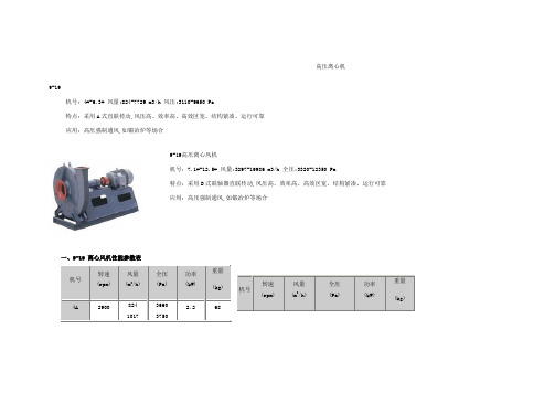
高压离心机9-19机号:4#-6.3# 风量:824-7729 m3/h 风压:3110-9650 Pa特点:采用A式直联传动,风压高、效率高、高效区宽、结构紧凑、运行可靠应用:高压强制通风,如锻冶炉等场合9-19高压离心风机机号:7.1#-12.5# 风量:3297-19986 m3/h 全压:3320-12350 Pa特点:采用D式联轴器直联传动,风压高、效率高、高效区宽、结构紧凑、运行可靠应用:高压强制通风,如锻冶炉等场合一、9-19 离心风机性能参数表机号转速(rpm)风量(m3/h)全压(Pa)功率(kW)重量(kg)4A29008241017 366037502.268机号转速(rpm)风量(m3/h)全压(Pa)功率(kW)重量(kg)120937201401 1594 1786 197836103470329031103764.5A29001174144817211995469048004760463041002269254328174450425040405.51205A2900161019862361273758505980594057707.5136311334883864558053305080111845.6A290022622790 74207560112089D145046955790688648404930491015720798190761017211267479046404470428018.577010D14506440794394451094812451602061306090595, , , 05780308901395315456557053603792011.2D1450904811115913270755076907640451360153811749274607250751600331775203845 4373 4901 54297320708067906500152406.3A290032213972472394809650959018.528854756226697877299360908087208370303687.1D2900461056856761121401235012280377007837891299881106412000116601123010810458608D290065941514075104019603217146990672096059907288878610183115813290335033303250315015123012979143763030291018.5130012.5D14501257815513184489410957095207517002138324317272523018793009030870083701102150960832710271412042002214008133 9672 1121115690 15600 1523012759 14288 15827148001426013720110107014503297406748363790386038407.5570560563757144791337403620347033201163012214417014157161001804319986408039603820367037154014D96011699144281715850045090504737230019888226182534828078491747094494424975297016D960174632153825613657066826627753780296876456110398033762 37837 419126180 5898 55759-26 离心风机性能参数表机号转速(rpm)风量(m3/h)全压(Pa)功率(kW)重量(kg)机号转速(rpm)风量(m3/h)全压(Pa)功率(kW)重量(kg)4A290021982473274830223297393038503740359034205.51149D14501251914804511050403090015649172141877920344219094920477045904380416045970 35723847321030007.51204.5A290035723847501049207.51323912 4303 4695 5086 5477479046104400416039001118010D14501717319320214666350625061105510902361325760279063005359405730548052207512505A2900429348305367590362306130596057501521011.2D14502412727143301593317579607850767074501102150 64406977751355105220492018.52305.6A29006030378678707740223003619039206718068701322250 75407540303508294 9048 9802 1055673007000667063104222265509601597417970199672196434703420334032403014606.3A290088589662107351002098609630454901180912882139561502993408990857081405558023961259572795431202980283037155012.5D9602220724982277584350428041904517907.1D29001229313830128001261075105015366169031233011970110150030534333104070392075224018439 19976 215131154011050105203608638862375035708.0D 290017585197831625016010132162014D960311993509954505370753100 2198221180263782857630774156501520014660140301336020017603899842898467985069854598525051004920471044801103220 1450879398921099140203950385018.571516D960465715239258213712070206860160370012090131893730358030800640356985666606420250466014289 14288 1538734103220756778149961505850二、9-19 9-26系列风机外形尺寸9-19 9-26系列4A-6.3A离心风机外形尺寸图、表系列机号D1D2D3n1-Φd1A1A2A3A4A5A6X Y n2-Φd29-194A1802202508-7128174214921381783210-7 4.5A2002502808-71441982301041521923210-7 5A2242653058-71602062461151602023210-75.6A2503083488-101792252651291742153210-76.3A2803353758-102022462881451892313210-7系列机号D1D2D3n1-Φd1A1A2A3A4A5A6X Y n2-Φd29-264A2242542848-71962282501281651844314-7 4.5A2502803108-1022125227514417723004314-7 5A2803203608-102452842991601922164314-75.6A3153553958-102743043281792162355414-76.3A3553954358-103093403652022362615410-7系列机号E F G K M N a b c d e f9-194A1083616922867154202003505030038535 4.5A1203447163227824502403905034043039 5A12637678825886850034045050440495435.6A14041587440196255035048050450534486.3A15746197545110856204505706057062655系列机号E F G K M N a b c d e f9-264A1323607112877614502403905034043049 4.5A1474057993228495003404505044049555 5A16545088735993955035048550450534615.6A186504993402105362045057060570626686.3A2095671117451116768055072070690780779-19 9-26系列7.1D-16D离心风机外形尺寸图、表系列机号D1D2A1A2A3A4A5A6n-Φd n1×b1n2×b29-197.1D31539522727231316321824814-103×684×68 8D35543625631234218424429414-103×764×74 9D40050628834839820726331318-104×635×66 10D45055032038642623030034018-101×695×7211.2D50062035942048425832838818-124×795×8312.5D56068040045648928834438020-124×866×7614D63075044851655732240544822-125×816×86 16D71083051257462136844048424-125×887×82系列机号D1D2A1A2A3,A4A5A6n-Φd n1×b1n2×b29-267.1D400500, <,/P>34839041422727229620-104×686×65 8D45055039343245825630032520-104×756×72 9D50062044148350728833035720-104×82.56×80.5 10D56068049052855632035638920-104×896×8811.2D63075054960063835841045026-125×828×7512.5D71083061366470240045649228-126×768×83 14D80092068674779544851656430-126×869×83 16D9001040,78484089351258862834-127×8410×84系列机号E F G H K N L0L W i jε9-197.1D17746668012005076561230210011504004504-68D20052576013505727331256222012504405204-6 9D22659085015206448211289193014005006004-6 10D25065694016807239081317206015005506506-811.2D2807351050189080110251595244017006008006-8 12.5D3138201160210089511401633255019007009008-10 14D350920128024001001127020302900205080095012-14 16D40010501440270011441460209034002250880104012-14系列机号E F G H K N L0L W i jε9-267.1D23763973012605097161317229012004205204-6 8D262720810141057408031349233014005006004-6 9D29481092015906469001392214015005506506-810D327900100017607179951433226016006007006-811.2D36710081130198080311221724266018507008508-1012.5D41811251240219089612471755269019507409408-10 14D4691260145025001003138022003350205080095012-14 16D52414401540280011481610227036502300900110012-14。
2021年《洁净区离心机清洁验证方案》
《洁净区离心机清洁验证方案》文件题目编码洁净区离心机(咪喹莫特用)清洁验证方案vop-xx450190起草执行日期日期日期日期替代——审核颁发部门质量管理部批准洁净区离心机(咪喹莫特用)清洁验证方案发放编码:天方药业有限公司目录一、目的..............................................................1二、适用范围..........................................................1三、职责..............................................................1四、内容..............................................................11、概述..............................................................12、风险评估结果......................................................13、参考资料..........................................................24、验证小组成员......................................................25、验证前资料检查....................................................36、验证原理..........................................................47、清洁方法及清洁产品................................................48、接受标准限度......................................................49、取样部位的确定....................................................510、取样方法及回收率测定.............................................511、检验方法.........................................................712、清洁验证结果.....................................................713、清洁有效期的验证.................................................814、偏差分析与整改...................................................915、结果分析及评价:.................................................916、再验证:.........................................................917、相关文件:.......................................................918、相关记录:.......................................................919、文件发放范围:...................................................920、附件:.. (9)天方药业有限公司洁净区离心机(咪喹莫特用)清洁验证方案vop-xx450190洁净区离心机(咪喹莫特用)清洁验证方案一、目的建立《洁净区离心机(咪喹莫特用)清洁验证方案》,确认用于咪喹莫特产品离心甩滤时,按《离心机(xx34)清洁标准操作规程》清洗后,设备上的的残留物不超过规定的清洁限度要求,不会对将生产的产品造成交叉污染,证明《离心机(xx34)清洁标准操作规程》的有效性,保证药品质量。
离心机常见故障及解决方法
离心机常见故障及解决方法
离心机是一种常见的机械设备,用于分离液体或颗粒物,常见于工业生产和实验室中。
虽然离心机的设计和制造趋于精确,但仍然有可能出现各种故障。
以下是离心机常见故障及其解决方法的一些例子:
1.离心机无法启动或停止:
2.离心机运行时产生异常噪音:
-解决方法:噪音通常是由于离心机的各种部件松动或磨损造成的。
检查离心机的固定螺钉和连接部件,确保它们紧固。
如果问题仍然存在,可能需要更换磨损的部件或进行其他维修。
3.离心机无法达到预定速度:
4.离心机运行时产生过多的热量:
-解决方法:过多的热量通常是由于离心机内部通风不良或过载导致的。
首先,确保离心机周围没有堵塞物,并且通风孔没有被堵住。
如果问题仍然存在,可能需要更换电机或其他关键部件。
5.离心机转速不稳定:
-解决方法:转速不稳定通常是由于离心机的电路或控制系统故障导致的。
首先,检查离心机电源是否稳定,并确保电路连接正确。
如果电源正常,但转速仍然不稳定,可能需要调整离心机的控制参数或更换控制系统。
6.离心机分离效果差:
-解决方法:分离效果差通常是由于离心机的转子或转子管堵塞导致的。
首先,检查离心机转子和转子管是否清洁,并确保没有堵塞物。
如果问题仍然存在,可能需要更换转子或转子管。
Alfa Laval LAPX404 离心机标准操作程序
Alfa Laval LAPX404 离心机标准操作程序1 目的正确使用Alfa Laval LAPX404 离心机2 范围Alfa Laval LAPX404 离心机3 责任人发酵组操作人员4 准备工作4.1 确认操作水压力可达到200—600 KPa4.2 确认压缩空气压力可达到400—800 KPa4.3 确认离心机机油是否超过所标明的最低液位4.4 确认手动刹车阀处于关闭状态。
4.5 用长螺丝刀拨动离心机转盘,观察并确认其处于均衡转动状态,无突然停滞现象4.6 确认所有的连接都是正确的4.7 确认调节阀201—7和222—4完全松开,对应的压力表读数为零。
确认手动阀305—2处于关闭状态,打开手动阀220—3、370—2。
5 操作程序5.1 打开主电源、操作水泵及压缩空气开关,调节操作水压力为200—600KPa,压缩空气压力为500—700KPa。
5.2 在离心机电源控制面板上,将电源开关由O转到I,此时主控制面板上显示为SdS5.3 调节压力阀222—4至压力为2.5bar左右。
5.4 按控制面板上①键开机,此时主控制面板上显示为STA,①键对应的绿灯会亮。
离心机开始工作,转速开始升高。
仔细观察离心机有无异常响声,控制板上电流有无异常变化,若有异常应立即停机。
5.5 待离心机转速升至工作转速后,按下PRODUCTION/STAND BY键直至键旁的绿灯亮起。
然后按下START/STOP键开始工作。
5.6 根据发酵和胰岛素包涵体提取工序的要求不同调节进料工作流速至适宜,调节阀PRV201—7至1的压力为4.5bar。
精细调节阀PRV201—8压力范围在1.1—1.2bar。
5.7 根据发酵和胰岛素包涵体提取工序的要求不同调节排渣时间至适宜。
5.8 离心结束,将进料管置于装有纯化水的桶中,调节进料工作流速至200—400L/h,清洗离心机转鼓。
清洗体积100—200L。
然后将进料管置于装有消毒剂的桶中,同样操作以对离心机转鼓进行消毒。
高速离心机使用说明书

使 用 说 明 书高 速 离 心 机安徽中科中佳科学仪器有限公司医疗器械生产许可证编号: 皖食药监械生产许20150020号 医疗器械生产备案号: 皖合食药监械生产备20150014 号 产品技术要求编号:皖合械备20150106号 产品备案号: 皖合械备20150106号适用机型:HC-1010/HC-1014/HC-1016/HC-1018HC-2062/HC-2064/ HC-2066/ HC-2068 HC-2518/HC-3018/ HC-3518HC-2514/HC-2515/ HC-2516/ HC-2517/ HC-3012 HC-3512/ HC-3513/ HC-3514/ HC-3515/ HC-3516编制日期:2016年4月目录前言1.11.21.34.14.25.15.25.35.45.5重要提示●严禁离心易燃、易爆、有剧烈化学反应及腐蚀性的化学品,否则会腐蚀腔体和转头等配件,严重时会导致机器损坏并危及人身安全!●离心机角转头、水平转头、吊杯等正常使用寿命为五年,过期后应立即联系生产单位更换新转头,否则可能损坏机器并危及人身安全!●仪器每次开机前,应认真检查转头的压紧螺母是否旋紧!●仪器在使用时,请务必使用单相三孔电源独立专用插座,并确保其可靠接地!●仪器工作时,应确保其工作电压在规定的范围内。
当仪器不能正常工作时,首先应检查电源电压是否正常!●为确保仪器及操作者安全,仪器运转时,转速的设定值不得超过其最高转速!●仪器断电后,请等待足够的时间(3min以上),方可再次打开电源!●离心样品装载前必须配平,各离心样品质量偏差不得大于5g,且要对称放入样品插孔中,如样品数量不成偶数,可用空试管加水配平后凑足。
否则,离心时会产生机器振动,并可能损坏机器!●离心样品平衡放置后,应双手同时用力关好门盖并确认门盖是否关好。
如门盖未关好,仪器将不能正常启动,此时应打开门盖再次重新关好门盖。
FC5306微量迷你离心机奥豪斯Ohaus产品操作说明书

Frontier TM离心机FC5306使用说明书奥豪斯国际贸易(上海)有限公司目录1产品简介 (1)1.1安全须知 (1)2安装 (2)2.1装箱单 (2)2.2更换或安装转子 (3)2.3供电 (4)2.4离心准备工作 (4)2.5离心 (工作状态) (4)3注意事项 (5)3.1供电装置 (5)3.2使用及维护 (5)4技术参数 (6)11 产品简介感谢您选用OHAUS 公司Frontier TM 系列离心机产品。
请在使用之前仔细阅读说明书以免造成不必要的损坏。
Frontier TM FC5306 性能前瞻:● 小而灵巧的机身,一键操作;● 无需工具即可快捷安装、更换转子;● 操作过程中若盖子打开,转子将立即停止运转; ● 电源供应使用直流输入;● 精心设计的产品,低噪音,使用寿命长;1.1安全须知请在安装、操作、维修前阅读安全须知,不遵循安全警告可能引起人身伤害或其他损失,请保留说明书。
操作人员安全预防措施● 请不要在有电火花可至爆炸危险的环境中工作 !因为仪器壳体并非气密性。
● 请使用化学品和溶剂时,遵照操作指南和实验室安全规程进行操作,以免造成人员损伤或仪表损坏。
● 安全空间内不得放置任何潜在危险物质。
● 禁止拆卸仪器,如需维修请联系技服人员。
● 仪器可防溅水, 但勿浸入水中。
● 不得依靠在离心机上。
● 安全空间内逗留时间不超过操作原因所需要的时间。
请避免下列情形影响仪表性能:● 剧烈的震动或撞击 ● 阳光直射● 湿度过大,高温或低温环境 ● 存在腐蚀性气体 ● 强电场磁场环境2 安装2.1 装箱单Frontier TM FC5306微量迷你离心机包括如下配置:22.2 更换或安装转子1. 当机器出厂时,它的套管和角转子已经固定在驱动电机的轴上。
2. 如果需要拆卸已安装的转子,用户需要手动握住转子的外缘,然后用两个手指朝着中心部位按压突出的固定夹钳,而后轻轻向上拿起转子。
3. 重新安装转子时,将带有夹钳的转子对齐椭圆形洞,向下按压转子,用拇指和另一支手的食指推着夹钳向着洞中心区,当听到声响后夹钳就重新固定好了。
lb800离心机设备验证方案(修改1)
LB-800平板式密闭离心机设备验证方案常州华夏农药有限公司2011年3月1.概述1.1验证方案名称:LB800平板式密闭离心机验证方案1.2验证方案文件编号:Ⅰ-Y01-004-001.3设备位置:双甲脒原药合成车间离心岗位1.4本公司设备编号:合S-0101.5设备数量:1台1.6设备概述(详见表1)表1 设备概述表1.7设备验证目的(详见表2)表2 设备验证程序及目的1.8验证方案的审批(详见表3)表3 设备验证方案审批表1.9验证方案发放登记(详见表4)表4 设备验证方案发放登记表1.10验证小组及设备使用单位的责任1.10.1验证小组责任1.10.1.1负责验证方案的审批;1.10.1.2负责验证的协调工作,保障本验证方案规定项目的顺利实施;1.10.1.3负责设备验证中各项数据的记录和整理;1.10.1.4负责验证数据和结果的审核;1.10.1.5负责验证报告的编制、审批;1.10.1.6负责设备验证周期的确认。
1.10.2设备使用单位(双甲脒合成车间/生产技术管理部)责任;1.10.2.1提供必要的现场及测试条件;1.10.2.2负责设备正常运行,对验证测试中与标准不符之处进行校正;1.10.3.3指定设备操作人员;1.10.3验证小组名单(详见表5)表5 设备验证小组名单1.11设备验证时间:年月日——年月日。
2.验证程序和实施步骤2.1设备基本情况(详见表6)表6 设备基本情况表2.2验证用测试仪器仪表、计量器具、检测设备(详见表7)表7 设备验证器具明细单2.3安装确认IQ2.3.1LB-800型离心机安装确认的项目2.3.1.1LB-800型离心机随机文件与配件的齐全确认;2.3.1.2检查LB-800型离心机安装地点能否满足双甲脒生产要求;2.3.1.3检查LB-800型离心机附带计量、仪器仪表;2.3.1.4检查配电系统能否满足LB-800型离心机的正常运行;2.3.2LB-800型离心机安装确认内容2.3.2.1LB-800型离心机随机文件齐全确认(详见表8)2.3.2.2LB-800型离心机主机与配件齐全确认(详见表9)2.3.2.3LB-800型离心机安装地点确认(详见表10)2.3.2.4离心机附带计量、仪表确认(详见表11)2.3.2.5离心机配套公用工程确认(详见表12)2.3.2安装确认结果评价2.4运行确认OQ2.4.1 LB-800型离心机运行确认项目2.4.1.1运行确认用计量器具的确认2.4.1.2离心机设备参数确认2.4.1.3离心机空载运行情况确认2.4.2相关的文件要求2.4.2.1离心机使用说明书、质量检测报告2.4.2.2离心机清洁、维护保养规程Ⅰ-生03-029-00 2.4.2.3双甲脒原料药合成岗位操作规程Ⅰ-生03-021-00 2.4.3离心机运行确认内容2.4.3.1离心机描述(详见表13)2.4.3.2离心机参数确认(详见表14)2.4.3.3离心机空载运行确认(详见表15)2.4.3.4运行确认用计量器具的确认(详见表16)表16 运行确认计量器具确认表2.4.4运行确认结果评价2.5性能确认PQ2.5.1实施性能确认前的准备工作的确认2.5.1.1安装确认IQ 、运行确认OQ完成确认(详见检查IQ、OQ报告)检查IQ、OQ报告2.5.1.2相关生产文件、清洁文件、设备维护文件完成确认(详见检查清单)检查清单2.5.1.3验证用计量器具、仪器校验完成确认(详见表17)表17 计量器具、仪器校验完成确认表2.5.2离心机性能确认内容2.5.2.1离心机运行时的主要工艺参数及产品含湿量确认。
中科科仪产品资料

<100Pa 27000 <5 精密陶瓷轴承 (需通保护气体) KF40(DN40 KF) DN160 LF、DN160 CF ≤0.1
4-8 ≤25 ≤100 5-40 150 内径Φ10 直插自密封 竖直±5° 29
10
真空获得产品 FF-160/700型脂润滑复合分子泵
FF-0/00型进气口法兰为: DN0LF、DN0CF
真空获得产品 FF15型分子泵
FF型进口法兰为:KF0
FF15型分子泵安装尺寸图(单位:mm)
FF15型抽速曲线
北京中科科仪技术发展有限责任公司
KYKY TECHNOLOGY DEVELOPMENT LTD.
FF15型分子泵技术性能
型号 抽气速率(L/S) 极限压强(Pa)
N2 压缩比(Max)
FF-100/110 110
N2: 108; H2: 5×10² ≤6×10⁻⁶ (DN100 LF) ≤6×10⁻⁷ (DN100 CF)
平板离心机URS - 4.26 -

平板式离心机用户需求版本修订索引目录1.介绍 (3)2.目的和范围 (3)2.1目的 (3)2.2范围 (3)3.职责 (4)4.缩写列表 (4)5.参考文件 (5)5.1标准/指南 (5)5.2相关文件 (5)6.设备描述 (5)7.用户及系统要求 (5)7.1设备工艺及材质要求 (5)7.2关键控制参数要求 (6)7.3环境健康安全(EHS)要求 (6)7.4安装要求 (7)7.5文件的要求 (7)7.6仪表的需求 (8)7.7确认与验证的需求 (8)7.8设备及材质运输要求 (8)7.9服务与维修要求 (9)7.10其他约束条件 (9)1.介绍生产三、四车间PBF系列平板式离心机,本文件是为该设备而编写的用户需求标准。
2.目的和范围2.1目的本文件旨在从离心机设备功能、技术指标、运行参数及EHS等方面提出用户的需求,目的是为以后离心机的采购合同、设备设计制造、安装调试及设备确认等提供充分的文件依据。
2.2范围本URS的范围涉及到了该类设备的最低要求,包括设计、生产、安装、检查和测试、文件、交付等过程。
供应商应以本URS作为详细设计以及报价的基础。
供应商在设计、制造、组装时必须要按照本URS来执行。
用于生产三、四车间PBF系列平板式离心机14台。
清单如下:3.职责4.缩写列表5.参考文件5.1标准/指南✓国家食品药品监督管理总局(CFDA),中国,药品生产质量管理规范(2010年修订)✓中华人民共和国制药机械行业标准 JB 20016-2004✓GB-52261-2002机械安全机械电气设备第一部分:通用技术条件✓JB/T10769.2-2007《三足式及平板式离心机第2部分:技术条件》✓GB/T10901-2005《离心机性能测试方法》✓GB/T10895-2004《离心机分离机机械振动测试方法》✓GB/T10894-2004《分离机机械噪音测试方法》5.2相关文件✓SMP-YZ-001-01《确认与验证管理规程》✓SMP-YZ-002-01《设备及公用系统验证管理规程》6.设备描述6.1设备介绍:离心机为PBF800和PBF1000的平板式全翻壳离心机。
eppendorf concentra说明书

eppendorf concentra说明书
1、离心机一定要放置在坚固、平稳、平整的水平台面或地板上,不能晃动。
2、先打开离心机样品仓盖子,检查是否存在异常,如有异常,先排除异常。
盖好盖子,接通电源。
设定一个基础转速和离心时间,转速可以设定为最大,时间设定为5分钟。
开启电源进行空转测试。
3、空转测试正常后,关闭电源。
打开样品仓。
将载有样品的试管对称放置在样品仓试管孔里。
4、注意放置样品试管时,一定要将同体积同质量的试管放置在对称位置。
如果质量不完全相同的,也要尽量将质量相近的、相差最小的放置在对称位置。
如果出现单一的样品,没有对称放置物品时,可以用相同或相近密度的液体代替装入离心管,放在对称位置,来完成离心工作。
通常用水代替。
5、样品离心参数的设定。
分离血液样品的离心转速可以设定在3500-4000转每分钟。
时间设定为5分钟。
其他如药液、浸膏这类的需要先尝试。
一般来说,样品的不溶物质与液体比重相差越大,越容易分离。
转速和时间都可以低和少。
相反,就是高和多了。
以分离血液样本为例,设定转速为4000转每分钟,离心时间为5分钟。
开启电源进行离心。
6、离心结束,关闭电源,打开样品仓盖子。
7、取出样品仓里面的样品,观察离心效果,如果效果达不到要
求,继续设定参数或增加时间或增加转速等进行调整,再次进行离心,直到满意为止。
样品达到离心效果后取出来必须竖直放在离心试管架上。
PF95LP 系列便携式过滤系统安装与操作手册说明书
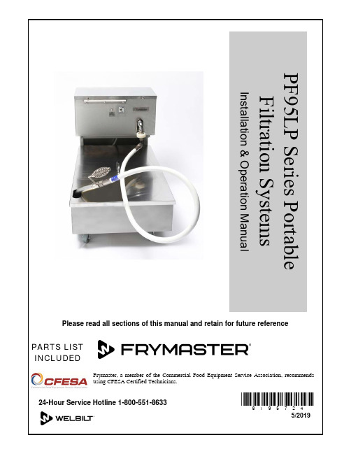
PARTS LISTINCLUDEDFrymaster, a member of the Commercial Food Equipment Service Association, recommendsusing CFESA Certified Technicians.24-Hour Service Hotline 1-800-551-8633*8195724*5/2019PF95LP Series Portable Filtration SystemsInstallation & Operation Manual Please read all sections of this manual and retain for future referenceInstallation, maintenance, and repairs should be performed by your Frymaster/Dean Factory Authorized Servicer.NOTICE:If this filter unit is cleaned with water, disconnect the unit from power source before cleaning and thoroughly dry the filter unit before reconnecting to electrical power source.NOTICE:Drawings and photos used in this manual are intended to illustrate operational, cleaning and technical procedures and may not conform to on-site management operational procedures.NOTICEIF, DURING THE WARRANTY PERIOD, THE CUSTOMER USES A PART FOR THIS FRYMASTER EQUIPMENT OTHER THAN AN UNMODIFIED NEW OR RECYCLED PART PURCHASED DIRECTLY FROM FRYMASTER DEAN, OR ANY OF ITS AUTHORIZED SERVICE CENTERS, AND/OR THE PART BEING USED IS MODIFIED FROM ITS ORIGINAL CONFIGURATION, THIS WARRANTY WILL BE VOID. FURTHER, FRYMASTER DEAN AND ITS AFFILIATES WILL NOT BE LIABLE FOR ANY CLAIMS, DAMAGES OR EXPENSES INCURRED BY THE CUSTOMER WHICH ARISE DIRECTLY OR INDIRECTLY, IN WHOLE OR IN PART, DUE TO THE INSTALLATION OF ANY MODIFIED PART AND/OR PART RECEIVED FROM AN UNAUTHORIZED SERVICE CENTER.PF95LP Series Portable Filtration SystemsInstallation & Operation ManualTABLE OF CONTENTSPage #1. INTRODUCTION 1-1INFORMATION 2-1 2. IMPORTANTINSTRUCTIONS 3-1 3. INSTALLATIONOPERATION 4-14. FILTER5. CLEANING AND MAINTENANCE 5-16. TROUBLESHOOTING 6-1LIST 7-1 7. PARTSPF95LP SERIES PORTABLE FILTRATION SYSTEMSCHAPTER 1: INTRODUCTION1.1 Parts Ordering/Service InformationPlace parts orders directly with your local Frymaster/Dean Factory Authorized Servicer (FAS). Your nearest Frymaster FAS is accessible at or you can contact the Frymaster Service Department at 1-800-24-FRYER or 1-318-865-1711.To help speed your order, the following information is required:Model Number TypeNumberSerialOptional FeaturesItem Part Number Quantity Needed1.2 Service InformationCall the 1-800-551-8633 or (318) 865-1711 Service Hotline number for the location of your nearest Factory Authorized Servicer. Always give the model and serial numbers of your filter unit. Also, identify if your unit is supplied with or without a heater.To assist you more efficiently, the following information will be needed:Model Number TypeSerial NumberOptional FeaturesNature of Problem:Additional information (i.e. oil temperature at filter time, time of day and other pertinent information) may be helpful in solving your service problem.PF95LP SERIES PORTABLE FILTRATION SYSTEMSCHAPTER 1: INTRODUCTION1.3 After PurchaseIn order to improve service, have the following chart filled in by the Authorized Service Technician who installed this equipment.Authorized ServiceTechnician/FASAddressTelephone/FaxModel NumberSerial Number1.4 Safety InformationBefore attempting to operate your unit, read the instructions in this manual thoroughly. Throughout this manual, you will find notations enclosed in double-bordered boxes similar to the ones below.PF95LP SERIES PORTABLE FILTRATION SYSTEMSCHAPTER 1: INTRODUCTION1.5 Service Personnel1.5.1 DefinitionsA.Qualified and/or Authorized Operating Personnel1.Qualified/authorized operating personnel are those who have carefully read the informationin this manual and have familiarized themselves with the equipment functions, or have had previous experience with the operation of equipment covered in this manual.B.Qualified Installation Personnel1.Qualified installation personnel are individuals, or firms, corporations, or companies that,either in person or through a representative, are engaged in and are responsible for theinstallation of electrical appliances. Qualified personnel must be experienced in such work, be familiar with all electrical precautions involved, and have complied with all requirements of applicable national and local codes.C.Qualified Service Personnel1.Qualified service personnel are those who are familiar with Frymaster/Dean equipment andhave been authorized by Frymaster/Dean to perform service on Frymaster/Dean equipment.All authorized service personnel are required to be equipped with a complete set of service parts manuals and stock a minimum amount of parts for Frymaster/Dean equipment.Failure to use qualified service personnel will void the Frymaster/Dean warranty on your equipment.PF95LP SERIES PORTABLE FILTRATION SYSTEMSCHAPTER 2: IMPORTANT INFORMATION2.1 GeneralPF95LP portable filters can be used with a variety of Frymaster fryers, as well as othermanufacturers’ equipment. Oil capacity is approximately 105 pounds. Unit specifications are listed below.Model Unit Height (inches) Unit Width (inches) Unit Length (inches) Tank Height (inches) Oil Capacity(pounds)PF95LP 24 18 33 ½ 9 105PF95LP Series filter unit dimensions (unit and tank heights are measured frombottom of casters to top of unit and tank, respectively).PF95LP SERIES PORTABLE FILTRATION SYSTEMS CHAPTER 2: IMPORTANT INFORMATION2.1 General (cont.)Oil or shortening is gravity-drained from the fryer into the filter, and then filtered through filter paper. Filter powder, which enhances the filtering process, is distributed over the paper prior to filtering.All units are shipped completely assembled with accessories packed inside the filter pan. All units are adjusted, tested and inspected at the factory before shipment.An ON/OFF switch activates/deactivates thefilter pump, and a 7-amp (120V), or 5-amp(230V) circuit breaker switches the power OFF ifan overload occurs. An internal backup thermal-overload switch on the pump-motor providesadditional protection. Remove the 6-Phillips headscrews and remove the motor housing to accessthe thermal overload reset switch.NOTE : If the circuit breaker is triggered,depress the reset button to activate thecircuit after the failure has beendetected and repaired.2.2 Rating Plate Information on the rating plate includes model and serial numbers, as well as electrical requirements. The rating plate is located on the back housing, near the electrical receptacle. Have the rating plate information handy when communicating with the factory about a unit or requesting special parts or information. Without rating plate information, proper identification of the unit cannot be confirmed.7-Amp circuit breaker On/Off SwitchNOTE: An additional thermal overload switch is on the filter motor. Remove the 6-Phillips head screws and then remove themotor housing cover to access the thermal overload switch.PF95LP SERIES PORTABLE FILTRATION SYSTEMSCHAPTER 2: IMPORTANT INFORMATION2.3 Pre-InstallationNOTE: Failure to use qualified service personnel will void the Frymaster/Dean warranty.A.Standards: Use of this filter unit must be in accordance with all applicable state and localcodes.B.Electrical Connections: Domestic PF95 filter units require a 115V 60 Hz., 15 amp electricalsupply. International/CE units require 230V 50 Hz., 7 amp electrical supply. Units areequipped with a grounded male receptacle for use with a 16-3 SJT power cord set. If anextension cord is required, it must be a three-conductor, grounded power cord of at least 16gauge.2.4 Unpacking the Filter SystemEnsure the container is upright. Unpack the filter carefully and remove all accessories from the carton. Do not discard or misplace parts and/or accessories; they will be needed for filter setup and operation. Any accessories or starter kits included with the unit will be packaged inside the filter tank.After unpacking, immediately check the equipment for visible signs of shipping damage. If such damage has occurred, contact the carrier and file the appropriate freight claims. Do not contact the factory, as the responsibility of shipping damage is between the carrier and dealer or end-user.If your equipment arrives damaged:a.File claim for damages immediately – Regardless of extent of damage.b.Visible loss or damage – Be sure this is noted on the freight bill or express receipt and issigned by the person making the delivery.c.Concealed loss or damage – If damage is unnoticed until equipment is unpacked, notifyfreight company or carrier immediately, and file a concealed damage claim. This should be done within 15 days of date of delivery. Retain the shipping container for inspection. NOTE: Frymaster does not assume responsibility for damage or loss incurred in transit.PF95LP SERIES PORTABLE FILTRATION SYSTEMSCHAPTER 3: FILTER PREPARATION3-13.1 Assembling The Filter SystemOn initial installation and before each use, remove all loose parts from the filter, wash the filter pan and all accessories in hot, soapy water and dry thoroughly.PF95LP Series portable filtration systems use a filter support grid, one sheet of filter paper and a hold-down ring to secure the filter paper in place.3.1.1 Filter Paper ConfigurationSee illustration for proper assembly. 1.Filter Pan Cover 2.Hold-Down Ring3.Filter Paper (one sheet)4.Screen/Support Grid5.Filter Pan AssemblyA.First, place the support grid in the bottom of filter pan.B.Place one sheet of filter paper on top of the support grid. Ensure the paper evenly covers the filter pan bottom.C.Position the hold-down ring on top of the filter paper and latch the hold-down ring and filter paper securely against the filter pan bottom, forming a tight seal.D.Sprinkle 8 ounces of filter powder over the filter paper, distributing the powder as evenly as possible. If filtering a second frypot immediately after the first, add only 4 ounces of filter powder for the second filtering.E.Place the crumb catcher screen (if applicable) in the filter pan. Allow the crumb catcher screento rest on the top edges of the hold-down ring.F.Place filter pan cover onto the filter pan assembly.PF95LP SERIES PORTABLE FILTRATION SYSTEMSCHAPTER 3: FILTER PREPARATION3-23.1.1 Filter Paper Configuration (cont.)G.Position filter under the fryer drainpipe to gravity drain the fryer. Lock the rear casters toprevent filter from moving out of position during the filtering process.PF95LP portable filter positioned correctly next to fryer drain valve, with rear casterslocked in place.PF95LP SERIES PORTABLE FILTRATION SYSTEMSCHAPTER 4: FILTER OPERATION4.1 GeneralPF95LP Series portable filters are designed to operate primarily as an independent filter unit. Operations always start by ensuring the unit is properly plugged in, then rolling the filter to the fryer to be filtered. The filter works directly under the fryers’ drain valves. The general layout of aPF95LP Series portable filter with major components identified is illustrated below.4-1PF95LP SERIES PORTABLE FILTRATION SYSTEMSCHAPTER 4: FILTER OPERATION4-24.2 Filtering ToolsThese tools are not required, but are recommended to make the filtering task easier. A.Measuring Cup: Used to measure eight ounces by volume of filter powder.B.Scrub Brush: To clean sediment and residue from the filter pan and frypot.C.Appropriate Clothing.4.3 Filter Preparation1.Position the PF95LP portable filter next to the fryer. Remove filter pan lid and positionfilter unit under frypot drain-valve extension.2.Ensure the filter power switch is in "OFF" position prior to connecting to power supply.3.Plug power cord into electrical outlet. The filter unit is ready for filtering. After filtering,follow instructions in Section 4.4, Changing Filter Paper.4.4 Changing Filter PaperFilter paper should be replaced after each filter session, and most certainly at the beginning of each workday. If filter paper is replaced once per day, excess sediment should be scraped from the filter paper after each frypot is filtered (see photo). Use care not to tear the paper when scraping off sediment. Filter at closing if possible. This ensures the oil is at proper filtering temperature.Note: If filtering at closing, remove and discardthe used filter paper in a fireproof containerwhen filter operations are complete. Wash allcomponents in soapy water and dry completely.If filtering more than one frypot with the samefilter paper, scrape excess sediment from the filter paper after each filtering.PF95LP SERIES PORTABLE FILTRATION SYSTEMSCHAPTER 4: FILTER OPERATION4-34.4 Changing Filter Paper (cont.)Remove and replace the paper as follows: 1.Remove filter cover. Place the hose wand in the wand holster, located on the left side of the pan (arrow).2.Open the locking latches of the hold-down ring and lift the ring out of the filter tank.3.Roll both ends of the filter paper into the center, ensuring no sediment falls out,and discard.Removing hold-down ring. Note location of wand holster (arrow).Removing dirty filter paper from pan.PF95LP SERIES PORTABLE FILTRATION SYSTEMSCHAPTER 4: FILTER OPERATION4-44.4 Changing Filter Paper (cont.)4.Remove and check the filter papersupport screen for cleanliness and clean if necessary.5.Check the filter-pan for cleanliness and clean if necessary; check the drain ports at the bottom rear of the filter pan and clear any solidified shortening from the opening (black arrow). Also ensure vent hole on top of tube is clear of shortening and/or debris (white arrow).6.Replace the filter paper support screen and place a new sheet of filter paper ontop of the screen.Removing paper support screen from pan.Solidified shortening can build-up in the nipple-pipe assembly (black arrow).Placing new sheet of filter paper over paper support screen.PF95LP SERIES PORTABLE FILTRATION SYSTEMSCHAPTER 4: FILTER OPERATION4-54.4 Changing Filter Paper (cont.)7. Replace the hold-down ring and secureby locking latches in place.8. Measure 8 ounces of filter powder anddistribute evenly over the paper surface.9. Replace filter pan cover. The filter isready for operation.Secure the hold-down ring latches to lock filter paper in place. Evenly distribute 8 ounces of filter powder over the filter paper surface. Filter unit ready for filtering operations.PF95LP SERIES PORTABLE FILTRATION SYSTEMSCHAPTER 4: FILTER OPERATION4.5 Unit Operation1.When filtering, follow these steps:2.Follow the appropriate instructions in Sections 4.3 and 4.4 to prepare the filter unit for operation.3.Position the filter unit under the fryer drain valve extension prior to draining fryer.4.Turn the fryer main power switch to the "OFF" position.5.Open the fryer door and place the filter in the proper position under the fryer drain valveextension (see photo below). Lock rear casters to prevent filter movement during the filtering process.4-6PF95LP SERIES PORTABLE FILTRATION SYSTEMSCHAPTER 4: FILTER OPERATION4-74.5 Unit Operation (cont.)6.Open the drain-valve and allow the frypot oil to drain into the filter pan.7. With the oil return wand in frypot, turn filter switch "ON" to begin pumping clean oil into the fryer. Allow the oil to recycle through the fryer for a few seconds to wash out sediment on the bottom of the frypot before closing the drain valve.Note: The oil return wand can also bemounted in the wand holster inside the pan,for extended filtering periods (polishing) priorto refilling frypot. NEVER LEAVE THE FILTER SYSTEM UNATTENDED WHILEFILTERING!Frypot draining into filter pan. Ensure oil is at operating temperature before opening drain valve. Use the nozzle to rinse sediment and debrisfrom the frypot during the filtering process ("U"units only).PF95LP SERIES PORTABLE FILTRATION SYSTEMSCHAPTER 4: FILTER OPERATION4-84.5 Unit Operation (cont.)8. When filtering is complete, close the drain valve handle. It takes approximately 5 to 7 minutes for the filter to pump all the oil back into the fryer.9. Allow the pump to run for 10-15 seconds after air starts to flow through the wand, before shutting off the filter. Clearing residual shortening or oil from the return lines reduces the likelihood of clogged lines.NOTE: After filtering, scrape off debris and sediment accumulated on the filter paper anddiscard into a fireproof container.NOTE:If filtration operations problems are encountered during use, please refer to Chapter 6 in this manual.PF95LP SERIES PORTABLE FILTRATION SYSTEMS CHAPTER 5: PREVENTATIVE MAINTENANCE5.1 GeneralCleaning operations fall into three general categories:∙Wiping unit clean, interior and exterior, after each filter session.∙Cleaning, changing filter paper and preparing the unit for the next day’s business.∙Weekly cleaning to remove oil deposits and other particles that were previously missed.5.2 Each Filter UseEach time the portable filter is used:∙Wash down the insides of the filter pan with hot oil during the filtering process. DO NOT allow excessive residue buildup to occur inside the filter pan.∙Change filter paper after each filter session or at the end of the day. Scrape sediment from filter paper after each frypot is filtered within a filter session. Do not filter more than three fryers per one sheet of filter paper.∙Wipe up any oil which may have splashed or spilled.∙Wipe all exterior surfaces of the filter unit.PF95LP SERIES PORTABLE FILTRATION SYSTEMSCHAPTER 5: PREVENTATIVE MAINTENANCE5.3 Daily- Close Of BusinessAt the close of a working day, filter the oil in all fryers. When the last fryer is finished, follow these steps:1.Ensure the flexible hose and pump lines are clear by running the filter pump for anadditional 10–15 seconds after air bubbles start coming from the oil return line. Then drain the flexible hose.2.Discard the filter paper after use.3.Remove the filter pan cover and hold-down ring assembly, then remove the filter paper andfilter support screen.4.Wash all filter components with soapy water and rinse.5.Dry all filter parts and filter pan thoroughly before reassembling.6.Check all fittings at the rear of the filter unit; ensure that all fittings are properly tightened.5.4 WeeklyFollow the same procedure as for "Daily", with these additional steps:∙Wash the filter pan with hot, soapy water and a brush. Dry and reassemble with new filter paper.∙Clean thoroughly under, around, and behind the fryers and filtering area.∙Do not operate motor/pump until all traces of water have been removed from the pan.Under no circumstances should water or boil-out solution be allowed to enter the pump housing; irreparable damage will result, and all warranties will be voided.∙Check the connections of the inlet lines and tighten if lines become loose or start to leak oil.PF95LP SERIES PORTABLE FILTRATION SYSTEMSCHAPTER 6: TROUBLESHOOTING6.1 Operating ProblemsPlugged lines and plugged filter paper account for over 90 percent of filtration system malfunctions.A general troubleshooting chart included in this chapter provides systematic instructions to assist the operator in diagnosing common malfunctions. Contact a factory-authorized service technician for troubleshooting beyond the scope of the operator.A.Plugged Lines1.To guard against plugged lines when using solid shortening, follow these guidelines:a.At the end of the filtering cycle, let the filter bubble into the fryer through the flexiblehose for about 10-15 seconds. If it is blowing bubbles, air is moving through the linesand the filter is less likely to be plugged.b.When filtering is complete, disconnect the flexible line and hang it up to drain.B.Plugged PaperImproper use of the filter powder will cause a slow oil flow return rate. The first indication of paper plugging is a surging, jerking movement of the hose. To correct this, review the instructions for the correct use of filter powder, and change the filter paper more frequently. When filtering several fryers prior to changing paper, ensure that excess sediment is scraped off the filter paper after filtering each frypot. If plugged paper remains a problem, review the chart in section 6.2 for proper diagnosis.6.2 General TroubleshootingThe following chart contains information to assist the user in diagnosing the most common malfunctions with portable filtration systems. Possible solutions and/or corrective actions are given for each scenario.If the malfunction cannot be diagnosed using the information in this section, contact your Factory Authorized Service Agent for repairs.PF95LP SERIES PORTABLE FILTRATION SYSTEMSCHAPTER 6: TROUBLESHOOTING6.2 General Troubleshooting (cont.)PF95LP SERIES PORTABLE FILTRATION SYSTEMSCHAPTER 6: TROUBLESHOOTING6.3 Wiring Diagrams6.3.1 PF95LP 120V Wiring6.3.2 PF95LP 230V WiringPF95LP SERIES PORTABLE FILTRATION SYSTEMSCHAPTER 7: PARTS LIST7.1 Main ComponentsItem Part # Description1 824-1089 Caster, Rear- Locking- 2"2 810-2141 Caster, Front- Swivel- 2"3 823-3613 Frame, Filter PF95 Series4 823-3680 Pan, Filter- PF95 Series* 809-0070 Nut, ¼-20 Hex SS (Filter Pan to Frame- 4 Required)* 809-0190 Washer, .625 x .275 x 40 Flat SS (Use With 809-0070)5 823-8435 Screen, Paper Support- PF95 Series* Not IllustratedPF95LP SERIES PORTABLE FILTRATION SYSTEMSCHAPTER 7: PARTS LIST7.1 Main Components (cont.)6 106-2032SP Ring, Hold-down Assy- 4-Handle PF95 Series* 810-2289Ring, Hold-down Assy- 6-Handle PF95 Series7 810-2108Handle, Latch (For Hold-Down Rings)* 809-0808Screw, Shoulder- 5/16-18 x 0.803" (For Latch Handles)8 210-1883Lid, Filter Pan- PF95 Series9 810-2105Handle, Chrome- Pan Lid* 809-0918Screw, #10-24 x ½" (Pan Lid Handle)* 809-0191Washer, ¼" Spring10 823-3684Housing, Top- Motor/ComponentSwitch11200-1542Housing,Housing12823-3590Back,Motor13 807-3577Breaker, Circuit- 7 Amp (120VAC)* 807-3538Breaker, Circuit- 5 Amp (230VAC)14 807-1041Switch, Toggle- On/Off SPST- "U" Series Only15 106-1831SP Disconnect, Quick Assembly- 3/8"16 813-0772Nipple, 3/8" NPT x Close- SS17 813-0691Elbow, ½ x 3/8" Chrome-Plated18 813-0761Nipple, ½ NPT x 5" SS5GPMFilter-19810-2252Pump,20 810-2100Motor, Filter Pump- 115/230V 1/3 HP* 807-3689Harness, Wire- Receptacle To Motor* 807-3752Harness, Wire- Motor To Switch/Circuit Breaker21 210-2955Bracket, Receptacle Mount- 120V Units Only* 210-3818Bracket, Receptacle Mount- 230V Units Only22 807-1219Receptacle, 120 VAC Three-Wire* 807-3795Receptacle, 230 VAC Three-Wire23 200-1588Tray, Pump and Motor24 807-1224Cordset, 120V Filter* 807-3831Connector, Export Plug- 230V (Cord Not Included)Rear25210-2978Cover,26 210-1570Cover, Switch/Circuit Breaker27 200-2956Bracket, Power Cord Storage*Not IllustratedPF95LP SERIES PORTABLE FILTRATION SYSTEMSCHAPTER 7: PARTS LIST7.2 Plumbing, Oil-Return Components and AccessoriesItem Part # Description1 813-0022Nipple, ½" NPT x Close2 813-0062Elbow, ½" NPT 90°3 810-1668Adapter, Male- 5/8 O.D. x ½" (Flexline to NPT)4 810-1400Flexline, 5/8 x 21"5 813-0629Plug, ½" NPT Square Head6 813-0003Tee, ½" NPT7 810-2172Connector, Disconnect- Male8 813-0632Elbow, Street- 3/8" 90° NPT BM9 810-2113Hose, ½ x 3/8" Fittings- 61-½" LongWandAssembly10106-1454SP*106-1455SPHose/Wand Assy- Complete (Items 7–10) * 803-0284Filter Paper, "16 3/x8 x 24 3/8” — 100 Sheets* 803-0002Filter Powder, Carton (80 1-Oz Applications) *Not IllustratedTHIS PAGE INTENTIONALLY LEFT BLANKFrymaster, L.L.C., 8700 Line Avenue, Shreveport, Louisiana 71106TEL 1-318-865-1711PRINTED IN THE UNITED STATES SERVICE HOTLINE1-800-551-863381957245/2019。
abi4500说明书
abi4500说明书ABI4500是一款先进的高速离心机,广泛用于生物医药、制药、化学、环保等领域。
它采用微机控制和变频技术,具有高速稳定的离心性能和先进的安全保护功能。
本说明书将详细介绍ABI4500的结构、参数、操作方法、维护和安全注意事项等内容。
一、结构ABI4500主要包含下面几个部分:离心机机身、离心转子、控制面板和安全装置。
离心机机身由高强度材料制成,结构紧凑且坚固,能有效抵抗离心过程中的振动和冲击。
离心转子通过螺纹接口与机身连接,同时设有锁紧装置确保离心转子的安全运行。
控制面板集成了所有操作按钮和显示屏,用户可以通过面板上的设置来调整离心机的参数和运行方式。
为了确保操作人员的安全,ABI4500还配备了多种安全装置,如超速保护装置、电机过热保护装置和门锁装置等。
二、参数1.最大转速:4500转/分钟;2.最大离心力:5050×g,可根据转子选择调整;3. 最大容量:1000ml;4.温度范围:-20°C至+40°C;5.定时功能:0-99分钟可调。
三、操作方法1.将样品注入离心转子中,确保样品均匀分布;2.安装离心转子,确认锁紧装置牢固;3.关闭离心机门,并将控制面板上的参数设置为所需值;4.按下启动按钮,离心机开始运转;5.运行结束后,按下停止按钮,等待离心机完全停止后再打开门取出样品。
四、维护1.定期清洁离心机机身、转子和控制面板;2.使用专用的润滑油对离心机的轴承和传动部件进行润滑;3.严格按照使用手册中说明的离心转子的容量和转速要求来操作;4.定期检查离心机的螺纹接口和锁紧装置,确保其正常工作;五、安全注意事项1.操作人员应佩戴防护眼镜和手套,避免样品飞溅导致伤害;2.离心过程中严禁用手接触旋转的离心转子;3.离心机需要接地保护,确保电源接地线正确连接;4.禁止对离心机进行未授权的操作和改装。
Eppendorf离心机使用宝典
● 使用经过认证的气密性转子和附件,可以防止在离心管意外破裂 的情况下气溶胶泄漏到环境中。由国际权威机构英国 Porton
Down 微生物研究中心测试和出具的证书可以保证您的安全。
● 冷冻型离心机因离心舱体离心时一直保持在密封状态因而可以
提供额外的保护。常温离心机因离心时需要进行空气热交换,转
● 在离心传染性样品时,应该使用可以保证即使离心管破裂也不泄 漏气溶胶的气密性转子和气密性盖子。气密性证书应由独立的第 三方出具。
● 使用可以在 121℃,20 分钟高温高压灭菌的转子,确保有效地 去除污染。
用 Ficoll 方法分离单核细胞
比较分离效果 (A) 离心时选用刹车功 能,重悬发生 (B) 离心时使用 “Soft
软刹车功能的离心机
● 带有 “at set rpm” 定速计时 功能的离心机,可以达到设定 速度后开始计时
2.5
2.5 应用指南五:离心细胞培养液
Eppendorf5702 RH Իयଌຝሎॶథ̾ʽҩᑞὙ ● “fast temp” ঋᤳଌຝ ● “standby heating” य़Ҫབ ● “soft brake” ᣃ҆ᢻ ● “at set rpm” ߿ᤳௐ
2.5
安全操作指南
Microcentrifuge 5430
3.1 正确操作离心机
务必事先阅读操作手册,注意: 离心机都是不同的 !
选择合适的转子
检查转子和舱体是否干燥
选择合适的离心管和高质量的适配器, 防止离心过程中离心管破裂
平衡离心管,对称摆放离心管 - 固定角转:分散摆放
- 水平转子:重量相同的吊篮对称摆放
子是一直暴露在环境中的。 A
(A) 带有气密性盖子 的水平转子 (B) 气密性固定角转 和转子盖 B
Alfdex油雾离心分离机:满足更严格的排放标准
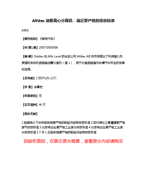
Alfdex油雾离心分离机:满足更严格的排放标准
余景宏
【期刊名称】《商用汽车》
【年(卷),期】2007(000)006
【摘要】Haldex和Alfa Laval的合资公司Alfdex AB向市场推出了利用离心机原理的发动机曲轴箱油雾分离机(图1),用于分离曲轴箱内吹漏气中所含的炭黑和油滴。
【总页数】2页(P126-127)
【作者】余景宏
【作者单位】无
【正文语种】中文
【相关文献】
1.我国将从下半年起实施更严格的船舶污染物排放标准
2.现代煤化工要遵循更严格废气排放标准
3.北京将出台更严格工业废水排放标准
4.北京将出台更严格工业废水排放标准
5.7月1日起实施更严格的船舶污染物排放标准
因版权原因,仅展示原文概要,查看原文内容请购买。
- 1、下载文档前请自行甄别文档内容的完整性,平台不提供额外的编辑、内容补充、找答案等附加服务。
- 2、"仅部分预览"的文档,不可在线预览部分如存在完整性等问题,可反馈申请退款(可完整预览的文档不适用该条件!)。
- 3、如文档侵犯您的权益,请联系客服反馈,我们会尽快为您处理(人工客服工作时间:9:00-18:30)。
hollow vertical bowl spindle. The bowl is fixed on top of the spindle, inside the space formed by the upper part of the frame, the solids collecting cover, and the frame hood. The hood carries the liquid discharge system.
All parts in contact with the process liquid are made of stain-less steel.
The bowl is of the solids ejecting disc type, with an automatic hydraulic operating system for “shooting”. The standard elec-tric motor is suitable for variable frequency drive.
Design features
The PX 95 is based on a unique, semi-hermetic design concept. The hermetic, bottom-fed inlet ensures a gentle, non-destructive acceleration of the feedstock up to full bowl speed. The flow area for the feedstock has been increased to minimize inlet pressure drop.
The outlets on the heavy and light phases are open, reducing the pressure drop across the separator. The feed-pressure requirement of the machine is therefore low.
The outlets are equipped with stationary paring devices for removal of the different phases. The paring disc on the light phase is fixed, while the paring tubes on the heavy phase are adjustable. PX 95 complete with motor
By adjusting a positioner on the heavy phase outlet, the operator can reduce or enlarge the paring diameter of the paring tubes. This patented innovation makes it possible to adjust the position of the separation interface during opera-tion, facilitating optimal separation.
With the working environment in mind, the PX 95 is designed to operate at low noise levels. This is achieved by means of a rubber-damped bearing assembly, jacketed frame and an outer bowl design engineered for low wind noise.
Standard equipment
Each PX 95 comes complete with control unit, electric motor, inlet and outlet connections, auxiliary equipment, a spare parts kit and a set of tools.
Operating principles
The oil to be separated is fed (1) into the separator bowl from the bottom through a hollow spindle (2), and enters the disc stack (3). The heavy phase and heavy sludge are forced towards the periphery of the bowl, while the light phase flows towards the centre of the bowl, from where it is pumped out (4) for further processing. The heavy phase is led over a top disc (5) into a chamber where an adjustable paring device pumps it out of the separator (6). Sludge collects in the sludge space (7) and is discharged intermittently and auto-matically. The discharge is achieved by a hydraulic system, which at preset suitable intervals forces the sliding bowl bottom (8) to drop down, thus opening the sludge ports at the bowl periphery. The sludge is collected in the frame, and leaves the centrifuge via a cyclone.PPM00006EN 0405How to contact Alfa Laval
Up-to-date Alfa Laval contact details for all countries are always available on our website at
Alfa Laval reserves the right to change specifications without prior notification.
Typical bowl drawing for solids ejecting hermetic centrifuge. Drawing details do not necessarily correspond to the centrifuge described.
Utilities consumption Electric power
max. 37 kW
Operating liquid, during discharge only 10 l/h Cooling water, jacket 300 l/h Cooling water, oil 80 l/h Sealing liquid
100 l/h Flushing liquid, per discharge 25–30 l
Technical specifications Throughput capacity max. 45 m 3/h Bowl speed 4,300 rpm
Bowl volume 66 l Sludge space
17 l Motor speed, synchronous 60.7 Hz 1,821 rpm
Motor power installed 37 kW Starting time
6–8 min Stopping time without brake 80 min Inlet pressure at 37 m 3/h 80 kPa Outlet pressure, oil
max. 500 kPa
Outlet pressure, heavy phase 0 kPa Sound pressure level
78 dB (A) Overhead hoist lifting capacity
min. 1,200 kg
Material data
Bowl body, hood and lock ring s.s. 1.4418 UNS Frame top part and hood s.s. 1.4401 UNS 31600Frame bottom part grey cast iron, clad with
s.s. 1.4301 UNS 30400
Gaskets and O-rings
nitrile rubber Shipping data (approximate)
Separator incl. bowl and motor 2,465 kg Bowl 1,050 kg Gross weight 2,990 kg Volume
5.4 m 3
Dimensions。