Phoenix支持云计算环境下瞬态过载的框架(IJITCS-V10-N2-4)
NVIDIA Jetson AGX Orin系列产品数据手册说明书
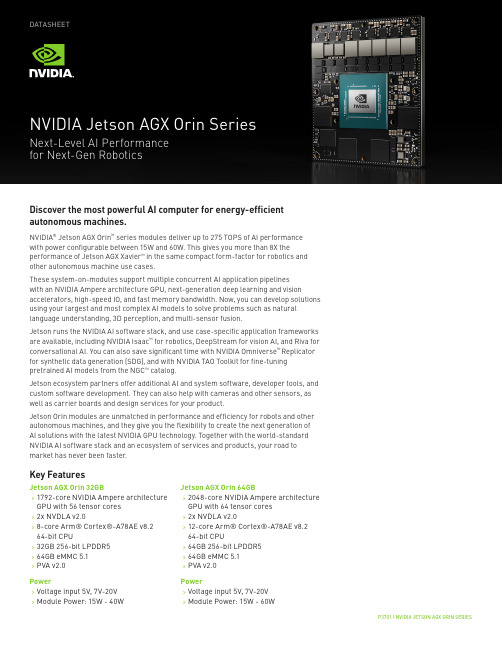
P3701 | NVIDIA JETSON AGX ORIN SERIESDATASHEETDiscover the most powerful AI computer for energy-efficient autonomous machines.NVIDIA ® Jetson AGX Orin ™ series modules deliver up to 275 TOPS of AI performance with power configurable between 15W and 60W. This gives you more than 8X theperformance of Jetson AGX Xavier ™ in the same compact form-factor for robotics and other autonomous machine use cases.These system-on-modules support multiple concurrent AI application pipelines with an NVIDIA Ampere architecture GPU, next-generation deep learning and visionaccelerators, high-speed IO, and fast memory bandwidth. Now, you can develop solutions using your largest and most complex AI models to solve problems such as natural language understanding, 3D perception, and multi-sensor fusion.Jetson runs the NVIDIA AI software stack, and use case-specific application frameworks are available, including NVIDIA Isaac ™ for robotics, DeepStream for vision AI, and Riva for conversational AI. You can also save significant time with NVIDIA Omniverse ™ Replicator for synthetic data generation (SDG), and with NVIDIA TAO Toolkit for fine-tuning pretrained AI models from the NGC ™ catalog.Jetson ecosystem partners offer additional AI and system software, developer tools, and custom software development. They can also help with cameras and other sensors, as well as carrier boards and design services for your product.Jetson Orin modules are unmatched in performance and efficiency for robots and other autonomous machines, and they give you the flexibility to create the next generation of AI solutions with the latest NVIDIA GPU technology. Together with the world-standard NVIDIA AI software stack and an ecosystem of services and products, your road to market has never been faster.Jetson AGX Orin 32GB>1792-core NVIDIA Ampere architecture GPU with 56 tensor cores >2x NVDLA v2.0>8-core Arm® Cortex®-A78AE v8.2 64-bit CPU>32GB 256-bit LPDDR5 >64GB eMMC 5.1 >PVA v2.0Power>Voltage input 5V, 7V-20V >Module Power: 15W - 40WKey FeaturesJetson AGX Orin 64GB>2048-core NVIDIA Ampere architecture GPU with 64 tensor cores >2x NVDLA v2.0>12-core Arm® Cortex®-A78AE v8.2 64-bit CPU>64GB 256-bit LPDDR5 >64GB eMMC 5.1 >PVA v2.0Power>Voltage input 5V, 7V-20V >Module Power: 15W - 60WNVIDIA JETSON AGX ORIN SERIES MODULES TECHNICAL SPECIFICATIONS* Virtual channel-related camera information for Jetson AGX Orin is not final and subject to change.Refer to the Software Features section of the latest NVIDIA Jetson Linux Developer Guide for a list of supportedfeatures.。
CLIP-SHIELD

CLIP-SHIELD ™Conductive Extrusionwith Mechanical AttachmentLEADER IN EMI SHIELDING INNOVATION, DESIGN, AND TEST TECHNOLOGY33DESCRIPTIONCLIP-SHIELD clip-on gaskets provide secure mechanical attachment of conductive elastomer gaskets for EMI shielding on electronic enclosures. This design replaces pressure sensitive adhesive tapes as a gasket attachment method. CLIP-SHIELD gaskets are ideally suited to small and large enclosure appli-cations requiring both high levels of EMI shielding and resistance to the outdoor environment.Standard CLIP-SHIELD gasketsconsist of a Chomerics CHO-SEAL ®con-ductive elastomer, which is adhesively attached to a flexible PVC/TPE-coated aluminum clip. Several CHO-SEAL con-ductive elastomer materials are available.These include S6305, which provides excellent shielding performance and environmental resistance, and 6370,which also is UL 94V-0 flammability rated.These conductive elastomers can be co-extruded with a non-conductive sili-cone for added environmental protection.FEATURES•55-120 dB shielding effectiveness from 200 MHz to 10 GHz•Excellent resistance to heat, humidity, salt fog corrosion and rain (with silver aluminum or nickel graphite fillers)•Choice of General Duty or UL 94V-0 rated versions •High strength mechanical gasket attachment to the enclosure •Easy manual installation•Available in 90-degree corner splice •2 in. (50.8 mm) min. bend radius for curved surfaces to avoid splicing •Clip sizes (H) from 0.06 in. (1.59 mm) to 0.5 in. (12.7 mm)•Conductive elastomer extrusion widths (w)available to 0.75 in. (19.05 mm)•Reliable, high strength bond between the elastomer gasket and PVC/TPE-coated clipBENEFITS•Economical installation•Single gasket design eliminates sepa-rate EMI and environmental seals •Alternative attachment method to pres-sure sensitive adhesives (PSA)•Global technical application supportOPTIMIZED GASKET SECTION •A wide range of CHO-SEAL conduc-tive materials are available •Custom gasket cross sections can be designed to meet specific applications.Clip widths (W) can be designed to a maximum of 0.75 in. (19.05 mm) •Co-extruded cross sections can be designed for extra environmental protection. CHO-SEAL conductive elastomers are extruded in parallel with a nonconductive silicone •Clip sizes (H) are available to accom-modate panel thicknesses from 0.06 in.(1.59 mm) to 0.50 in. (12.7mm) Typical Part Number 19-24-XXXX(X)-ZZZZ(Z) XXXX(X) Profile ZZZZ(Z) Materialeg. 19-24-16966-S6305All extruded conductive elastomers are available in CLIP-SHIELD. Contact Chomerics Application Department for assistance.Typical CLIP-SHIELD GasketCross Section0.391 in.(9.931 mm)0.563 in.(14.300 mm)0.344 in.(8.737 mm)0.313 in.(7.950 mm)HWChomerics,Div. of Parker Hannifin 77 Dragon CourtWoburn, MA 01888-4014Tel: 781-935-4850FAX:781-933-4318Parker Hannifin PLC Chomerics Europe Parkway, Globe ParkMarlow, Bucks, SL7 1YB, United Kingdom Tel:(44) 1628 404000FAX:(44) 1628 404090NOTICE: The information contained herein is to the best of our knowledge true and accurate. However, since the varied conditions of potential use are beyond our control, all recommendations or suggestions are presented without guarantee or responsibility on our part and users should make their own tests to determine the suitability of our products in any specific situation. This product is sold without warranty either expressed or implied, of fitness for a particular purpose or otherwise, except that this product shall be of standard quality, and except to the extent otherwise stated on Chomerics’ invoice, quotation, or order acknowledgement. We disclaim any and all liability incurred in connection with the use of information contained herein, or otherwise. All risks of such are assumed by the user. Furthermore, nothing contained herein shall be construed as a recommendation to use any process or to manufacture or to use any product in conflict with existing or future patents covering any product or material or its use.©Chomerics, div. of Parker Hannifin Corp., 2000Printed in U.S.A.Parker Hannifin Hong Kong Ltd.Chomerics Sales Department 8/F King Yip Plaza9 Cheung Yee Street, Cheung Sha Wan Kowloon, Hong Kong Tel: (852) 2 428 8008Fax: (852) 2 423 82537M1100ST -249Shown below are the specifications of the two most commonly used materials.CLIP-SHIELD CONDUCTIVE EXTRUSION WITH MECHANICAL ATTACHMENTMin.corner radius 2 in.(50.8 mm)90-degree spliced cornerCONDUCTIVE ELASTOMER SPECIFICATIONSTEST PROCEDURE CHO-SEAL S6305CHO-SEAL 6370Conductive Filler Ni/C Ni/C Elastomer Binder SiliconeSiliconeVolume Resistivity CEPS-0002*0.100.10(ohm-cm, max)Volume Resistivity after Heat Aging, 150°C/48 hrs.CEPS-0002*0.250.25(ohm-cm, max.)Hardness (Shore A, ±10)ASTM D2*******Specific Gravity (±0.25)ASTM D792 2.0 2.1 Tensile Strength psi (Mpa), min.ASTM D624200 (1.38)150 (1.03)Elongation (percent, min.)ASTM D412100100Compression Set, 70 hrs. ASTM D395**40 6.3@ 100°C (percent max.)Method B FlammabilityUL94--V-0 (wall >0.014 in./ 0.356 mm)Low Temperature Flex TR10 ASTM D1329-45-45(°C, min.)Corrosion Resistance CHO-TM-100*3535(weight loss mg)Maximum Continuous Use 150150Temperature (°C)Shielding Effectiveness (dB)100 MHz (E field)100100500 MHz (E field)CHO-TM-TP08*1001002 GHz (Plane Wave)1009510 GHz (Plane Wave)10095* Copies of CEPS-0002, CHO-TM-100 and CHO-TM-TP08 are available from Chomerics.** Compression set is expressed as a percentage of deflection per ASTM D395 Method B, at 25% deflection. T o determine percentrecovery, subtract 1/4 of stated compression set value from 100%. For example, in the case of 30% compression set, recovery is 92.5%.。
菲尼克斯简介

行业资讯 => 菲尼克斯—世界防雷及电涌保护科技的领先者【打印此页】【返回】发布日期:[2005-4-10] 共阅[872]次随着国内防雷市场的启动和日趋成熟,越来越多国际知名防雷及电涌保护产品生产商进入了国内市场。
最近我们专程采访了世界防雷及电涌保护科技的领先者――菲尼克斯电气有限公司的有关负责人。
一、世界防雷及电涌保护产品的领先者德国PHOENIX CONTACT集团公司创建于1923年,公司总部设在德国的勃朗贝克城,现有职员五千余名,在全球50多个国家设有子公司和合作伙伴,年销售额超过30亿欧元。
专业生产各种高品质的电连接器接插件、电子模块、信号变送器、现场总线、防雷防浪涌过电压保护系统等产品,产品遍及所有的工业领域。
为电力、电子、通讯、机械、建筑、石油、化工、航空、交通、铁路运输、汽车制造、机械电气装置等行业提供产品和服务。
为满足客户的需求而不断创新的研发理念和为客户提供的专业化、快捷的服务,以及建立于ISO9001和ISO14001标准基础上的过程控制管理系统,确保了PHOENIX CONTACT公司的组合接线端子、电子接口技术,印刷线路板连接技术、防雷及电涌保护装置与方案,以及开放式的传感器/执行器现场总线系统(INTERBUS)等高质量产品取得了全球市场的领先地位。
二、巨大的市场潜力和良好的合作关系使德国PHOENIX CONTACT公司对其在中国的发展充满信心作为德国菲尼克斯集团在中国大陆唯一的子公司,南京菲尼克斯电气有限公司自1993年成立以来,在中德双方政府的共同推动及公司员工的不懈努力下,通过严格的质量管理推动产品创新、服务创新,生产规模和销售规模不断扩大,呈现出快速发展的态势,在不到10年的时间里,已发展为德国菲尼克斯电气集团最大的海外生产基地,并连续多年被列为江苏省重点外商投资工业企业,“ AAA”资信企业,南京市外商投资先进企业、南京市高新技术企业、南京市高利税企业、南京市做出特殊贡献企业、南京市三资企业管理工作先进单位。
2023上半年 国产操作系统(麒麟)安全管理师(初级)考前冲刺题A1卷

2023上半年国产操作系统(麒麟)安全管理师(初级)考前冲刺题A1卷1.【单选题】哈希也称“散列”函数或“杂凑”函数,它是一个( )。
A:可逆函数B:可逆映射C:不可逆的单向映射D:双向映射正确答案:C答案解析:哈希也称“散列”函数或“杂凑”函数,它是一个不可逆的单向映射2.【单选题】双体系架构包括( )。
A:通用计算体系和专用计算体系B:TPM和TPCMC:TPM和TCMD:通用计算体系和可信计算体系正确答案:D答案解析:双体系架构包括通用计算体系和可信计算体系。
3.【单选题】可信根由( )组成。
A:TPM和TPCMB:TPCM和TCMC:TPM和TCMD:TPCM正确答案:B答案解析:可信根由TCM和TPCM组成4.【单选题】将一个用户的( )则此用户就拥有了root权限。
A:UID改为0B:UID改为1C:UID改为1000D:UID改为1001正确答案:A答案解析:系统通过UID标识用户,0是root用户的UID5.【单选题】PAM模块配置文件保存在( )中。
A:/etc/profile.dB:/etc/pam.confC:/etc/pam.dD:/etc/profile.conf正确答案:C答案解析:PAM配置文件保存在/etc/pam.d目录中,且以程序的名称为文件名。
用以控制每个程序的登录验证。
6.【单选题】银河麒麟操作系统通过( )进行指纹认证。
A:pam_unix.so模块B:pam_biometric.soC:access.confD:pam_env.conf正确答案:B答案解析:pam_unix.so模块用于密码口令认证,pam_biometric.so用于指纹等生物特征识别认证7.【单选题】( )是指对某个客体具有拥有权的主体能够将对该客体的访问权自主地授予其它主体,并在随后的任何时刻将这些权限回收。
A:DACB:ACLC:MACD:RBAC正确答案:A答案解析:自主访问控制(DAC,Discretionary Access Control)是指对某个客体具有拥有权的主体能够将对该客体的访问权自主地授予其它主体,并在随后的任何时刻将这些权限回收。
德尔·韦玛网络S4048T-ON交换机说明书

The Dell EMC Networking S4048T-ON switch is the industry’s latest data center networking solution, empowering organizations to deploy modern workloads and applications designed for the open networking era. Businesses who have made the transition away from monolithic proprietary mainframe systems to industry standard server platforms can now enjoy even greater benefits from Dell EMC open networking platforms. By using industry-leading hardware and a choice of leading network operating systems to simplify data center fabric orchestration and automation, organizations can tailor their network to their unique requirements and accelerate innovation.These new offerings provide the needed flexibility to transform data centers. High-capacity network fabrics are cost-effective and easy to deploy, providing a clear path to the software-defined data center of the future with no vendor lock-in.The S4048T-ON supports the open source Open Network Install Environment (ONIE) for zero-touch installation of alternate network operating systems, including feature rich Dell Networking OS.High density 1/10G BASE-T switchThe Dell EMC Networking S-Series S4048T-ON is a high-density100M/1G/10G/40GbE top-of-rack (ToR) switch purpose-builtfor applications in high-performance data center and computing environments. Leveraging a non-blocking switching architecture, theS4048T-ON delivers line-rate L2 and L3 forwarding capacity within a conservative power budget. The compact S4048T-ON design provides industry-leading density of 48 dual-speed 1/10G BASE-T (RJ45) ports, as well as six 40GbE QSFP+ up-links to conserve valuable rack space and simplify the migration to 40Gbps in the data center core. Each40GbE QSFP+ up-link can also support four 10GbE (SFP+) ports with a breakout cable. In addition, the S4048T-ON incorporates multiple architectural features that optimize data center network flexibility, efficiency and availability, including I/O panel to PSU airflow or PSU to I/O panel airflow for hot/cold aisle environments, and redundant, hot-swappable power supplies and fans. S4048T-ON supports feature-rich Dell Networking OS, VLT, network virtualization features such as VRF-lite, VXLAN Gateway and support for Dell Embedded Open Automation Framework.• The S4048T-ON is the only switch in the industry that supports traditional network-centric virtualization (VRF) and hypervisorcentric virtualization (VXLAN). The switch fully supports L2 VX-• The S4048T-ON also supports Dell EMC Networking’s Embedded Open Automation Framework, which provides enhanced network automation and virtualization capabilities for virtual data centerenvironments.• The Open Automation Framework comprises a suite of interre-lated network management tools that can be used together orindependently to provide a network that is flexible, available andmanageable while helping to reduce operational expenses.Key applicationsDynamic data centers ready to make the transition to software-defined environments• High-density 10Gbase-T ToR server access in high-performance data center environments• Lossless iSCSI storage deployments that can benefit from innovative iSCSI & DCB optimizations that are unique only to Dell NetworkingswitchesWhen running the Dell Networking OS9, Active Fabric™ implementation for large deployments in conjunction with the Dell EMC Z-Series, creating a flat, two-tier, nonblocking 10/40GbE data center network design:• High-performance SDN/OpenFlow 1.3 enabled with ability to inter-operate with industry standard OpenFlow controllers• As a high speed VXLAN Layer 2 Gateway that connects thehypervisor based ovelray networks with nonvirtualized infrastructure Key features - general• 48 dual-speed 1/10GbE (SFP+) ports and six 40GbE (QSFP+)uplinks (totaling 72 10GbE ports with breakout cables) with OSsupport• 1.44Tbps (full-duplex) non-blocking switching fabric delivers line-rateperformance under full load with sub 600ns latency• I/O panel to PSU airflow or PSU to I/O panel airflow• Supports the open source ONIE for zero-touch• installation of alternate network operating systems• Redundant, hot-swappable power supplies and fansDELL EMC NETWORKING S4048T-ON SWITCHEnergy-efficient 10GBASE-T top-of-rack switch optimized for data center efficiencyKey features with Dell EMC Networking OS9Scalable L2 and L3 Ethernet switching with QoS and a full complement of standards-based IPv4 and IPv6 features, including OSPF, BGP and PBR (Policy Based Routing) support• Scalable L2 and L3 Ethernet switching with QoS and a full complement of standards-based IPv4 and IPv6 features, including OSPF, BGP andPBR (Policy Based Routing) support• VRF-lite enables sharing of networking infrastructure and provides L3traffic isolation across tenants• Increase VM Mobility region by stretching L2 VLAN within or across two DCs with unique VLT capabilities like Routed VL T, VLT Proxy Gateway • VXLAN gateway functionality support for bridging the nonvirtualizedand the virtualized overlay networks with line rate performance.• Embedded Open Automation Framework adding automatedconfiguration and provisioning capabilities to simplify the management of network environments. Supports Puppet agent for DevOps• Modular Dell Networking OS software delivers inherent stability as well as enhanced monitoring and serviceability functions.• Enhanced mirroring capabilities including 1:4 local mirroring,• Remote Port Mirroring (RPM), and Encapsulated Remote PortMirroring (ERPM). Rate shaping combined with flow based mirroringenables the user to analyze fine grained flows• Jumbo frame support for large data transfers• 128 link aggregation groups with up to 16 members per group, usingenhanced hashing• Converged network support for DCB, with priority flow control(802.1Qbb), ETS (802.1Qaz), DCBx and iSCSI TLV• S4048T-ON supports RoCE and Routable RoCE to enable convergence of compute and storage on Active FabricUser port stacking support for up to six units and unique mixed mode stacking that allows stacking of S4048-ON with S4048T-ON to providecombination of 10G SFP+ and RJ45 ports in a stack.Physical48 fixed 10GBase-T ports supporting 100M/1G/10G speeds6 fixed 40 Gigabit Ethernet QSFP+ ports1 RJ45 console/management port with RS232signaling1 USB 2.0 type A to support mass storage device1 Micro-USB 2.0 type B Serial Console Port1 8 GB SSD ModuleSize: 1RU, 1.71 x 17.09 x 18.11”(4.35 x 43.4 x 46 cm (H x W x D)Weight: 23 lbs (10.43kg)ISO 7779 A-weighted sound pressure level: 65 dB at 77°F (25°C)Power supply: 100–240V AC 50/60HzMax. thermal output: 1568 BTU/hMax. current draw per system:4.6 A at 460W/100VAC,2.3 A at 460W/200VACMax. power consumption: 460 WattsT ypical power consumption: 338 WattsMax. operating specifications:Operating temperature: 32°F to 113°F (0°C to45°C)Operating humidity: 5 to 90% (RH), non-condensing Max. non-operating specifications:Storage temperature: –40°F to 158°F (–40°C to70°C)Storage humidity: 5 to 95% (RH), non-condensingRedundancyHot swappable redundant powerHot swappable redundant fansPerformance GeneralSwitch fabric capacity:1.44Tbps (full-duplex)720Gbps (half-duplex)Forwarding Capacity: 1080 MppsLatency: 2.8 usPacket buffer memory: 16MBCPU memory: 4GBOS9 Performance:MAC addresses: 160KARP table 128KIPv4 routes: 128KIPv6 hosts: 64KIPv6 routes: 64KMulticast routes: 8KLink aggregation: 16 links per group, 128 groupsLayer 2 VLANs: 4KMSTP: 64 instancesVRF-Lite: 511 instancesLAG load balancing: Based on layer 2, IPv4 or IPv6headers Latency: Sub 3usQOS data queues: 8QOS control queues: 12Ingress ACL: 16KEgress ACL: 1KQoS: Default 3K entries scalable to 12KIEEE compliance with Dell Networking OS9802.1AB LLDP802.1D Bridging, STP802.1p L2 Prioritization802.1Q VLAN T agging, Double VLAN T agging,GVRP802.1Qbb PFC802.1Qaz ETS802.1s MSTP802.1w RSTP802.1X Network Access Control802.3ab Gigabit Ethernet (1000BASE-T)802.3ac Frame Extensions for VLAN T agging802.3ad Link Aggregation with LACP802.3ae 10 Gigabit Ethernet (10GBase-X) withQSA802.3ba 40 Gigabit Ethernet (40GBase-SR4,40GBase-CR4, 40GBase-LR4) on opticalports802.3u Fast Ethernet (100Base-TX)802.3x Flow Control802.3z Gigabit Ethernet (1000Base-X) with QSA 802.3az Energy Efficient EthernetANSI/TIA-1057 LLDP-MEDForce10 PVST+Max MTU 9216 bytesRFC and I-D compliance with Dell Networking OS9General Internet protocols768 UDP793 TCP854 T elnet959 FTPGeneral IPv4 protocols791 IPv4792 ICMP826 ARP1027 Proxy ARP1035 DNS (client)1042 Ethernet Transmission1305 NTPv31519 CIDR1542 BOOTP (relay)1812 Requirements for IPv4 Routers1918 Address Allocation for Private Internets 2474 Diffserv Field in IPv4 and Ipv6 Headers 2596 Assured Forwarding PHB Group3164 BSD Syslog3195 Reliable Delivery for Syslog3246 Expedited Assured Forwarding4364 VRF-lite (IPv4 VRF with OSPF, BGP,IS-IS and V4 multicast)5798 VRRPGeneral IPv6 protocols1981 Path MTU Discovery Features2460 Internet Protocol, Version 6 (IPv6)Specification2464 Transmission of IPv6 Packets overEthernet Networks2711 IPv6 Router Alert Option4007 IPv6 Scoped Address Architecture4213 Basic Transition Mechanisms for IPv6Hosts and Routers4291 IPv6 Addressing Architecture4443 ICMP for IPv64861 Neighbor Discovery for IPv64862 IPv6 Stateless Address Autoconfiguration 5095 Deprecation of T ype 0 Routing Headers in IPv6IPv6 Management support (telnet, FTP, TACACS, RADIUS, SSH, NTP)VRF-Lite (IPv6 VRF with OSPFv3, BGPv6, IS-IS) RIP1058 RIPv1 2453 RIPv2OSPF (v2/v3)1587 NSSA 4552 Authentication/2154 OSPF Digital Signatures Confidentiality for 2328 OSPFv2 OSPFv32370 Opaque LSA 5340 OSPF for IPv6IS-IS1142 Base IS-IS Protocol1195 IPv4 Routing5301 Dynamic hostname exchangemechanism for IS-IS5302 Domain-wide prefix distribution withtwo-level IS-IS5303 3-way handshake for IS-IS pt-to-ptadjacencies5304 IS-IS MD5 Authentication5306 Restart signaling for IS-IS5308 IS-IS for IPv65309 IS-IS point to point operation over LANdraft-isis-igp-p2p-over-lan-06draft-kaplan-isis-ext-eth-02BGP1997 Communities2385 MD52545 BGP-4 Multiprotocol Extensions for IPv6Inter-Domain Routing2439 Route Flap Damping2796 Route Reflection2842 Capabilities2858 Multiprotocol Extensions2918 Route Refresh3065 Confederations4360 Extended Communities4893 4-byte ASN5396 4-byte ASN representationsdraft-ietf-idr-bgp4-20 BGPv4draft-michaelson-4byte-as-representation-054-byte ASN Representation (partial)draft-ietf-idr-add-paths-04.txt ADD PATHMulticast1112 IGMPv12236 IGMPv23376 IGMPv3MSDP, PIM-SM, PIM-SSMSecurity2404 The Use of HMACSHA- 1-96 within ESPand AH2865 RADIUS3162 Radius and IPv63579 Radius support for EAP3580 802.1X with RADIUS3768 EAP3826 AES Cipher Algorithm in the SNMP UserBase Security Model4250, 4251, 4252, 4253, 4254 SSHv24301 Security Architecture for IPSec4302 IPSec Authentication Header4303 ESP Protocol4807 IPsecv Security Policy DB MIBdraft-ietf-pim-sm-v2-new-05 PIM-SMwData center bridging802.1Qbb Priority-Based Flow Control802.1Qaz Enhanced Transmission Selection (ETS)Data Center Bridging eXchange (DCBx)DCBx Application TLV (iSCSI, FCoE)Network management1155 SMIv11157 SNMPv11212 Concise MIB Definitions1215 SNMP Traps1493 Bridges MIB1850 OSPFv2 MIB1901 Community-Based SNMPv22011 IP MIB2096 IP Forwarding T able MIB2578 SMIv22579 T extual Conventions for SMIv22580 Conformance Statements for SMIv22618 RADIUS Authentication MIB2665 Ethernet-Like Interfaces MIB2674 Extended Bridge MIB2787 VRRP MIB2819 RMON MIB (groups 1, 2, 3, 9)2863 Interfaces MIB3273 RMON High Capacity MIB3410 SNMPv33411 SNMPv3 Management Framework3412 Message Processing and Dispatching forthe Simple Network ManagementProtocol (SNMP)3413 SNMP Applications3414 User-based Security Model (USM) forSNMPv33415 VACM for SNMP3416 SNMPv23417 Transport mappings for SNMP3418 SNMP MIB3434 RMON High Capacity Alarm MIB3584 Coexistance between SNMP v1, v2 andv34022 IP MIB4087 IP Tunnel MIB4113 UDP MIB4133 Entity MIB4292 MIB for IP4293 MIB for IPv6 T extual Conventions4502 RMONv2 (groups 1,2,3,9)5060 PIM MIBANSI/TIA-1057 LLDP-MED MIBDell_ITA.Rev_1_1 MIBdraft-grant-tacacs-02 TACACS+draft-ietf-idr-bgp4-mib-06 BGP MIBv1IEEE 802.1AB LLDP MIBIEEE 802.1AB LLDP DOT1 MIBIEEE 802.1AB LLDP DOT3 MIB sFlowv5 sFlowv5 MIB (version 1.3)DELL-NETWORKING-SMIDELL-NETWORKING-TCDELL-NETWORKING-CHASSIS-MIBDELL-NETWORKING-PRODUCTS-MIBDELL-NETWORKING-SYSTEM-COMPONENT-MIBDELL-NETWORKING-TRAP-EVENT-MIBDELL-NETWORKING-COPY-CONFIG-MIBDELL-NETWORKING-IF-EXTENSION-MIBDELL-NETWORKING-FIB-MIBIT Lifecycle Services for NetworkingExperts, insights and easeOur highly trained experts, withinnovative tools and proven processes, help you transform your IT investments into strategic advantages.Plan & Design Let us analyze yourmultivendor environment and deliver a comprehensive report and action plan to build upon the existing network and improve performance.Deploy & IntegrateGet new wired or wireless network technology installed and configured with ProDeploy. Reduce costs, save time, and get up and running cateEnsure your staff builds the right skills for long-termsuccess. Get certified on Dell EMC Networking technology and learn how to increase performance and optimize infrastructure.Manage & SupportGain access to technical experts and quickly resolve multivendor networking challenges with ProSupport. Spend less time resolving network issues and more time innovating.OptimizeMaximize performance for dynamic IT environments with Dell EMC Optimize. Benefit from in-depth predictive analysis, remote monitoring and a dedicated systems analyst for your network.RetireWe can help you resell or retire excess hardware while meeting local regulatory guidelines and acting in an environmentally responsible way.Learn more at/lifecycleservicesLearn more at /NetworkingDELL-NETWORKING-FPSTATS-MIBDELL-NETWORKING-LINK-AGGREGATION-MIB DELL-NETWORKING-MSTP-MIB DELL-NETWORKING-BGP4-V2-MIB DELL-NETWORKING-ISIS-MIBDELL-NETWORKING-FIPSNOOPING-MIBDELL-NETWORKING-VIRTUAL-LINK-TRUNK-MIB DELL-NETWORKING-DCB-MIBDELL-NETWORKING-OPENFLOW-MIB DELL-NETWORKING-BMP-MIBDELL-NETWORKING-BPSTATS-MIBRegulatory compliance SafetyCUS UL 60950-1, Second Edition CSA 60950-1-03, Second Edition EN 60950-1, Second EditionIEC 60950-1, Second Edition Including All National Deviations and Group Differences EN 60825-1, 1st EditionEN 60825-1 Safety of Laser Products Part 1:Equipment Classification Requirements and User’s GuideEN 60825-2 Safety of Laser Products Part 2: Safety of Optical Fibre Communication Systems FDA Regulation 21 CFR 1040.10 and 1040.11EmissionsInternational: CISPR 22, Class AAustralia/New Zealand: AS/NZS CISPR 22: 2009, Class ACanada: ICES-003:2016 Issue 6, Class AEurope: EN 55022: 2010+AC:2011 / CISPR 22: 2008, Class AJapan: VCCI V-3/2014.04, Class A & V4/2012.04USA: FCC CFR 47 Part 15, Subpart B:2009, Class A RoHSAll S-Series components are EU RoHS compliant.CertificationsJapan: VCCI V3/2009 Class AUSA: FCC CFR 47 Part 15, Subpart B:2009, Class A Available with US Trade Agreements Act (TAA) complianceUSGv6 Host and Router Certified on Dell Networking OS 9.5 and greater IPv6 Ready for both Host and RouterUCR DoD APL (core and distribution ALSAN switch ImmunityEN 300 386 V1.6.1 (2012-09) EMC for Network Equipment\EN 55022, Class AEN 55024: 2010 / CISPR 24: 2010EN 61000-3-2: Harmonic Current Emissions EN 61000-3-3: Voltage Fluctuations and Flicker EN 61000-4-2: ESDEN 61000-4-3: Radiated Immunity EN 61000-4-4: EFT EN 61000-4-5: SurgeEN 61000-4-6: Low Frequency Conducted Immunity。
联想Flex System Fabric EN4093R 10Gb可扩展交换机产品指南说明书
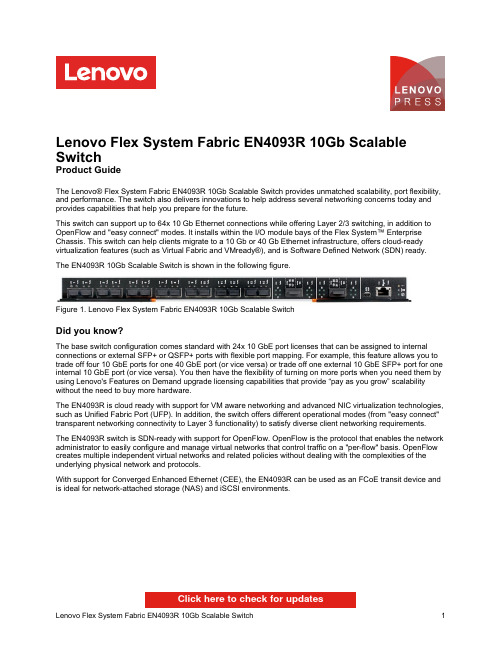
Lenovo Flex System Fabric EN4093R 10Gb Scalable SwitchProduct GuideThe Lenovo® Flex System Fabric EN4093R 10Gb Scalable Switch provides unmatched scalability, port flexibility, and performance. The switch also delivers innovations to help address several networking concerns today and provides capabilities that help you prepare for the future.This switch can support up to 64x 10 Gb Ethernet connections while offering Layer 2/3 switching, in addition to OpenFlow and "easy connect" modes. It installs within the I/O module bays of the Flex System™ Enterprise Chassis. This switch can help clients migrate to a 10 Gb or 40 Gb Ethernet infrastructure, offers cloud-ready virtualization features (such as Virtual Fabric and VMready®), and is Software Defined Network (SDN) ready. The EN4093R 10Gb Scalable Switch is shown in the following figure.Figure 1. Lenovo Flex System Fabric EN4093R 10Gb Scalable SwitchDid you know?The base switch configuration comes standard with 24x 10 GbE port licenses that can be assigned to internal connections or external SFP+ or QSFP+ ports with flexible port mapping. For example, this feature allows you to trade off four 10 GbE ports for one 40 GbE port (or vice versa) or trade off one external 10 GbE SFP+ port for one internal 10 GbE port (or vice versa). You then have the flexibility of turning on more ports when you need them by using Lenovo's Features on Demand upgrade licensing capabilities that provide “pay as you grow” scalability without the need to buy more hardware.The EN4093R is cloud ready with support for VM aware networking and advanced NIC virtualization technologies, such as Unified Fabric Port (UFP). In addition, the switch offers different operational modes (from "easy connect" transparent networking connectivity to Layer 3 functionality) to satisfy diverse client networking requirements.The EN4093R switch is SDN-ready with support for OpenFlow. OpenFlow is the protocol that enables the network administrator to easily configure and manage virtual networks that control traffic on a "per-flow" basis. OpenFlow creates multiple independent virtual networks and related policies without dealing with the complexities of the underlying physical network and protocols.With support for Converged Enhanced Ethernet (CEE), the EN4093R can be used as an FCoE transit device and is ideal for network-attached storage (NAS) and iSCSI environments.Click here to check for updatesFigure 2. Front panel of the Flex System Fabric EN4093R 10Gb Scalable SwitchThe front panel includes the following components:System LEDs that display the status of the switch module and the network.One mini-USB RS-232 console port that provides another means to configure the switch module.14x SFP/SFP+ ports to attach SFP/SFP+ transceivers for 1 GbE or 10 GbE connections or SFP+ DAC cables for 10 GbE connections.2x QSFP+ ports to attach QSFP+ transceivers or DAC cables for 40 GbE or 4x 10 GbE connections.1x RJ-45 10/100/1000 Mb Ethernet port for out-of-band management.The supported transceivers and cables are listed in the following table. Table 5. Supported transceivers and direct-attach cablesDescription Part number FeaturecodeMaximumquantitysupportedSerial console cablesFlex System Management Serial Access Cable Kit90Y9338A2RR1 SFP transceivers - 1 GbELenovo 1000BASE-T (RJ-45) SFP Transceiver (no 10/100 Mbps support)00FE333A5DL14 Lenovo 1000BASE-SX SFP Transceiver81Y1622326914 Lenovo 1000BASE-LX SFP Transceiver90Y9424A1PN14 SFP+ transceivers - 10 GbELenovo Dual Rate 1/10Gb SX/SR SFP+ Transceiver00MY034ATTJ14 Lenovo 10Gb SFP+ SR Transceiver (10GBASE-SR)46C3447505314 Lenovo 10GBASE-LR SFP+ Transceiver00FE331B0RJ14 Lenovo 10GBASE-T SFP+ Transceiver7G17A03130AVV114 Optical cables for 1 GbE SX SFP, 10 GbE SR SFP+, and 40 GbE SR QSFP+ BiDi transceiversLenovo 1m LC-LC OM3 MMF Cable00MN502ASR614 Lenovo 3m LC-LC OM3 MMF Cable00MN505ASR714 Lenovo 5m LC-LC OM3 MMF Cable00MN508ASR814 Lenovo 10m LC-LC OM3 MMF Cable00MN511ASR914 Lenovo 15m LC-LC OM3 MMF Cable00MN514ASRA14 Lenovo 25m LC-LC OM3 MMF Cable00MN517ASRB14 Lenovo 30m LC-LC OM3 MMF Cable00MN520ASRC14 SFP+ active optical cables - 10 GbELenovo 1m SFP+ to SFP+ Active Optical Cable00YL634ATYX14 Lenovo 3m SFP+ to SFP+ Active Optical Cable00YL637ATYY14 Lenovo 5m SFP+ to SFP+ Active Optical Cable00YL640ATYZ14 Lenovo 7m SFP+ to SFP+ Active Optical Cable00YL643ATZ014 Lenovo 15m SFP+ to SFP+ Active Optical Cable00YL646ATZ114 Lenovo 20m SFP+ to SFP+ Active Optical Cable00YL649ATZ214 SFP+ direct-attach cables - 10 GbELenovo 1m Passive SFP+ DAC Cable90Y9427A1PH14 Lenovo 1.5m Passive SFP+ DAC Cable00AY764A51N14 Lenovo 2m Passive SFP+ DAC Cable00AY765A51P14 Lenovo 3m Passive SFP+ DAC Cable90Y9430A1PJ14 Lenovo 5m Passive SFP+ DAC Cable90Y9433A1PK14 Lenovo 7m Passive SFP+ DAC Cable00D6151A3RH14 QSFP+ transceivers - 40 GbELenovo 40GBase QSFP+ Bi-Directional Transceiver00YL631ATYW2 Lenovo 40GBASE-SR4 QSFP+ Transceiver49Y7884A1DR2 Lenovo 40GBASE-iSR4 QSFP+ Transceiver00D9865ASTM2 Lenovo 40GBASE-eSR4 QSFP+ Transceiver00FE325A5U92 Lenovo 40GBASE-LR4 QSFP+ Transceiver00D6222A3NY2Optical cables for 40 GbE QSFP+ SR4/iSR4/eSR4 transceivers Lenovo 10m QSFP+ MPO-MPO OM3 MMF Cable 00VX003AT2U 2Lenovo 30m QSFP+ MPO-MPO OM3 MMF Cable00VX005AT2V 2Optical breakout cables for 40 GbE QSFP+ iSR4/eSR4 transceivers Lenovo 1m MPO-4xLC OM3 MMF Breakout Cable 00FM412A5UA 2Lenovo 3m MPO-4xLC OM3 MMF Breakout Cable 00FM413A5UB 2Lenovo 5m MPO-4xLC OM3 MMF Breakout Cable 00FM414A5UC2QSFP+ active optical cables - 40 GbELenovo 1m QSFP+ to QSFP+ Active Optical Cable 7Z57A04256AX422Lenovo 3m QSFP+ to QSFP+ Active Optical Cable 00YL652ATZ32Lenovo 5m QSFP+ to QSFP+ Active Optical Cable 00YL655ATZ42Lenovo 7m QSFP+ to QSFP+ Active Optical Cable 00YL658ATZ52Lenovo 15m QSFP+ to QSFP+ Active Optical Cable 00YL661ATZ62Lenovo 20m QSFP+ to QSFP+ Active Optical Cable 00YL664ATZ72QSFP+ active optical breakout cables - 40 GbE to 4x10 GbE Lenovo 1M QSFP+ to 4xSFP+ Active Optical Cable 00YL667ATZ82Lenovo 3M QSFP+ to 4xSFP+ Active Optical Cable 00YL670ATZ92Lenovo 5M QSFP+ to 4xSFP+ Active Optical Cable 00YL673ATZA 2QSFP+ direct-attach cables - 40 GbE Lenovo 1m Passive QSFP+ DAC Cable 49Y7890A1DP 2Lenovo 3m Passive QSFP+ DAC Cable 49Y7891A1DQ 2Lenovo 5m Passive QSFP+ DAC Cable 00D5810A2X82Lenovo 7m Passive QSFP+ DAC Cable 00D5813A2X92QSFP+ breakout cables - 40 GbE to 4x10 GbELenovo 1m Passive QSFP+ to SFP+ Breakout DAC Cable 49Y7886A1DL 2Lenovo 3m Passive QSFP+ to SFP+ Breakout DAC Cable 49Y7887A1DM 2Lenovo 5m Passive QSFP+ to SFP+ Breakout DAC Cable49Y7888A1DN2DescriptionPart number Featurecode Maximum quantity supportedThe network cables that can be used with the switch are listed in the following table.Table 6. EN4093R network cabling requirementsTransceiver Standard Cable Connector 40 Gb Ethernet40Gb SR QSFP+ BiDi (00YL631)40GBASE-SRBiDiUp to 30 m with fiber optic cables supplied by Lenovo (seeTable 5); up to 100 m with OM3 or up to 150 m with OM4multimode fiber optic cable.LC40Gb SR4 QSFP+ (49Y7884)40GBASE-SR410 m or 30 m MPO fiber optic cables supplied byLenovo (see Table 5); up to 100 m with OM3 or up to 150 mwith OM4 multimode fiber optic cable.MPO40Gb iSR4 QSFP+ (00D9865)40GBASE-SR410 m or 30 m MPO fiber optic cables or MPO-4xLCbreakout cables up to 5 m supplied by Lenovo (see Table5); up to 100 m with OM3 or up to 150 m with OM4multimode fiber optic cable.MPO40Gb eSR4 QSFP+ (00FE325)40GBASE-SR410 m or 30 m MPO fiber optic cables or MPO-4xLCbreakout cables up to 5 m supplied by Lenovo (see Table5); up to 300 m with OM3 or up to 400 m with OM4multimode fiber optic cable.MPO40Gb LR4 QSFP+(00D6222)40GBASE-LR41310 nm single-mode fiber optic cable up to 10 km.LCActive optical cable40GBASE-SR4QSFP+ to QSFP+ active optical cables up to 1 m; QSFP+to 4x SFP+ active optical break-out cables up to 5 m for 4x10 GbE SFP+ connections out of a 40 GbE port (see Table5)QSFP+Direct attach copper cable40GBASE-CR4QSFP+ to QSFP+ DAC cables up to 7 m; QSFP+ to4x SFP+ DAC break-out cables up to 5 m for 4x 10 GbESFP+ connections out of a 40 GbE port (see Table 5).QSFP+ 10 Gb Ethernet10Gb SR SFP+ (46C3447) 1/10Gb SFP+ (00MY034)10GBASE-SR Up to 30 m with fiber optic cables supplied by Lenovo (seeTable 5); up to 300 m with OM3 or up to 400 m with OM4multimode fiber optic cable.LC10Gb LR SFP+ (00FE331)10GBASE-LR1310 nm single-mode fiber optic cable up to 10 km.LC 10Gb RJ-45 SFP+(7G17A03130)10GBASE-T UTP Category 6a or 7 up to 30 meters.RJ-45 Active optical cable10GBASE-SR SFP+ active optical cables up to 20 m (see Table 5)SFP+ Direct attach copper cable10GSFP+Cu SFP+ DAC cables up to 7 m (see Table 5).SFP+ 1 Gb Ethernet1Gb RJ-45 SFP (00FE333)1000BASE-T UTP Category 5, 5E, or 6 up to 100 meters.RJ-451Gb SX SFP (81Y1622) 1/10Gb SFP+ (00MY034)1000BASE-SX Up to 30 m with fiber optic cables supplied by Lenovo (seeTable 5); 850 nm multimode fiber cable 50 µ (OM2) up to550 m or 62.5 µ (OM1) up to 220 m.LC1Gb LX SFP (90Y9424)1000BASE-LX1310 nm single-mode fiber optic cable up to 10 km.LC Management ports1 GbE management port1000BASE-T UTP Category 5, 5E, or 6 up to 100 meters.RJ-45 RS-232 management port RS-232DB-9-to-mini-USB or RJ-45-to-mini-USB console cable(comes with the optional Cable Kit, 90Y9338).Mini-USBFigure 3. Location of the I/O bays in the Flex System Enterprise ChassisThe EN4093R switches can be installed in bays 1, 2, 3, and 4 of the Enterprise chassis. A supported adapter must be installed in the corresponding slot of the compute node. Each adapter can use up to four lanes to connect to the respective I/O module bay. The EN4093R can use up to three of the four lanes.In compute nodes that have an integrated dual-port 10 GbE network interface controller (NIC), NIC ports are routed to bays 1 and 2 with a specialized periscope connector, and the adapter is not required. However, the periscope connector can be replaced with the adapter when needed. In such a case, integrated NIC is disabled. With flexible port mapping, there is no need to buy switch upgrades for 4-port and 8-port adapters if the total number of port licenses on the switch does not exceed the number of external (upstream network ports) and internal (compute node network ports) connections that are used.The following table shows compatibility information for the EN4093R and Flex System chassis.Table 7. Flex System chassis compatibilityThe midplane connections between the adapters that are installed in the compute nodes to the I/O module bays in the chassis are listed in the following table. Half-wide compute nodes support up to two adapters, and full-wide compute nodes support up to four adapters.Table 8. Adapter to I/O bay correspondenceI/O adapter slotin the compute node Port on the adapter Corresponding I/O module bay in the chassisBay 1Bay 2Bay 3Bay 4Slot 1Port 1YesPort 2YesPort 3YesPort 4YesPort 5YesPort 6YesPort 7*Port 8*Slot 2Port 1YesPort 2YesPort 3YesPort 4YesPort 5YesPort 6YesPort 7*Port 8*Slot 3(full-wide compute nodes only)Port 1YesPort 2Yes Port 3YesPort 4Yes Port 5YesPort 6Yes Port 7*Port 8*Slot 4(full-wide compute nodes only)Port 1YesPort 2Yes Port 3YesPort 4Yes Port 5YesPort 6Yes Port 7*Port 8** Ports 7 and 8 are routed to I/O bays 1 and 2 (Slot 1 and Slot 3) or 3 and 4 (Slot 2 and Slot 4), but these ports cannot be used with the EN4093R switch.The following table lists the adapters that are supported by the I/O module.Table 9. Network adaptersDescription Part number Featurecode50 Gb EthernetThinkSystem QLogic QL45212 Flex 50Gb 2-Port Ethernet Adapter7XC7A05843B2VT ThinkSystem QLogic QL45262 Flex 50Gb 2-Port Ethernet Adapter with iSCSI/FCoE7XC7A05845B2VV25 Gb EthernetThinkSystem QLogic QL45214 Flex 25Gb 4-Port Ethernet Adapter7XC7A05844B2VU10 Gb EthernetEmbedded 10Gb Virtual Fabric Adapter (2-port)†None None Flex System CN4052S 2-port 10Gb Virtual Fabric Adapter00AG540ATBT Flex System CN4052S 2-port 10Gb Virtual Fabric Adapter Advanced01CV780AU7X Flex System CN4054S 4-port 10Gb Virtual Fabric Adapter00AG590ATBS Flex System CN4054S 4-port 10Gb Virtual Fabric Adapter Advanced01CV790AU7Y1 Gb EthernetEmbedded 1 Gb Ethernet controller (2-port)*None None† The Embedded 10Gb Virtual Fabric Adapter is built into selected compute nodes.* The Embedded 1 Gb Ethernet controller is built into selected compute nodes.Network connectivityThe following table lists the 10 Gb, 25 Gb, and 40 Gb Ethernet network switches that are offered by Lenovo that can be used with the EN4093R switch in Flex System network connectivity solutions.Table 10. Network switchesDescription Part number 10 Gb Ethernet switchesLenovo ThinkSystem NE1032 RackSwitch (Rear to Front)7159A1X Lenovo ThinkSystem NE1032T RackSwitch (Rear to Front)7159B1X Lenovo ThinkSystem NE1064TO RackSwitch (Rear to Front, ONIE)7Z330O11WW Lenovo ThinkSystem NE1072T RackSwitch (Rear to Front)7159C1X Lenovo RackSwitch G8272 (Rear to Front)7159CRW25 Gb Ethernet switchesLenovo ThinkSystem NE2572 RackSwitch (Rear to Front)7159E1X Lenovo ThinkSystem NE2572O RackSwitch (Rear to Front, ONIE)7Z210O21WW Lenovo ThinkSystem NE2580O RackSwitch (Rear to Front, ONIE)7Z330O21WW 100 Gb Ethernet switches (support 40 GbE connectivity)Lenovo ThinkSystem NE10032 RackSwitch (Rear to Front)7159D1X Lenovo ThinkSystem NE10032O RackSwitch (Rear to Front, ONIE)7Z210O11WWFor more information, see the list of Product Guides in the Top-of-rack Switches category:/servers/options/switchesStorage connectivityThe following table lists the external storage systems that are currently offered by Lenovo that can be used with the EN4093R switch for external NAS or iSCSI SAN storage connectivity.Table 11. External storage systems: DE SeriesDescription Part number Worldwide JapanLenovo ThinkSystem DE2000HLenovo ThinkSystem DE2000H 10GBASE-T Hybrid Flash Array LFF (16 GB cache)7Y70A003WW7Y701001JP Lenovo ThinkSystem DE2000H 10GBASE-T Hybrid Flash Array SFF (16 GB cache)7Y71A002WW7Y711005JP Lenovo ThinkSystem DE2000H iSCSI Hybrid Flash Array LFF (16 GB cache)7Y70A004WW7Y701000JP Lenovo ThinkSystem DE2000H iSCSI Hybrid Flash Array SFF (16 GB cache)7Y71A003WW7Y711006JP Lenovo ThinkSystem DE4000HLenovo ThinkSystem DE4000H iSCSI Hybrid Flash Array 4U60 (16 GB cache)7Y77A000WW7Y771002JP Lenovo ThinkSystem DE4000H iSCSI Hybrid Flash Array LFF (16 GB cache)7Y74A002WW7Y74A002JP Lenovo ThinkSystem DE4000H iSCSI Hybrid Flash Array SFF (16 GB cache)7Y75A001WW7Y75A001JP Lenovo ThinkSystem DE4000FLenovo ThinkSystem DE4000F iSCSI All Flash Array SFF (16 GB cache)7Y76A002WW7Y76A002JP Lenovo ThinkSystem DE4000F iSCSI All Flash Array SFF (64 GB cache)7Y76A007WW7Y76A00AJP Lenovo ThinkSystem DE6000HLenovo ThinkSystem DE6000H iSCSI Hybrid Flash Array 4U60 (32 GB cache)7Y80A002WW7Y801000JP Lenovo ThinkSystem DE6000H iSCSI Hybrid Flash Array SFF (32 GB cache)7Y78A002WW7Y781000JP Lenovo ThinkSystem DE6000FLenovo ThinkSystem DE6000F iSCSI All Flash Array SFF (128 GB cache)7Y79A002WW7Y79A002JPTable 12. External storage systems: DM SeriesDescription Part number Lenovo ThinkSystem DM3000HThinkSystem DM3000H Hybrid Storage Array (2U12 LFF, CTO only)7Y42CTO1WW ThinkSystem DM3000H, 48TB (12x 4TB HDDs), 10GBASE-T, ONTAP 9.5 Fundamentals7Y421003EA* ThinkSystem DM3000H, 48TB (12x 4TB HDDs), 10GBASE-T, ONTAP 9.57Y421007EA* ThinkSystem DM3000H, 48TB (12x 4TB HDDs), 16Gb FC / 10GbE SFP+, ONTAP 9.5 Fundamentals7Y421009NA* ThinkSystem DM3000H, 48TB (12x 4TB HDDs), 16Gb FC / 10GbE SFP+, ONTAP 9.5 Fundamentals7Y421002EA* ThinkSystem DM3000H, 48TB (12x 4TB HDDs), 16Gb FC / 10GbE SFP+, ONTAP 9.57Y421006EA* ThinkSystem DM3000H, 96TB (12x 8TB HDDs), 10GBASE-T, ONTAP 9.5 Fundamentals7Y421005EA* ThinkSystem DM3000H, 96TB (12x 8TB HDDs), 10GBASE-T, ONTAP 9.57Y421001EA* ThinkSystem DM3000H, 96TB (12x 8TB HDDs), 16Gb FC / 10GbE SFP+, ONTAP 9.5 Fundamentals7Y421004EA* ThinkSystem DM3000H, 96TB (12x 8TB HDDs), 16Gb FC / 10GbE SFP+, ONTAP 9.57Y421008EA* Lenovo ThinkSystem DM5000HThinkSystem DM5000H Hybrid Storage Array (2U24 SFF, CTO only)7Y57CTO1WW ThinkSystem DM5000H, 11.5TB (12x 960GB SSDs), 10GBASE-T, ONTAP 9.5 Fundamentals7Y571004EA* ThinkSystem DM5000H, 11.5TB (12x 960GB SSDs), 10GBASE-T, ONTAP 9.57Y57100LEA* ThinkSystem DM5000H, 11.5TB (12x 960GB SSDs), 16Gb FC / 10GbE SFP+, ONTAP 9.5 Fundamentals7Y571011NA* ThinkSystem DM5000H, 11.5TB (12x 960GB SSDs), 16Gb FC / 10GbE SFP+, ONTAP 9.5 Fundamentals7Y571003EA*Description Part number ThinkSystem DM5000H, 11.5TB (12x 960GB SSDs), 16Gb FC / 10GbE SFP+, ONTAP 9.57Y57100KEA* ThinkSystem DM5000H, 14.4TB (12x 1.2TB HDDs), 10GBASE-T, ONTAP 9.5 Fundamentals7Y57100CEA*7Y57100BEA* ThinkSystem DM5000H, 14.4TB (12x 1.2TB HDDs), 16Gb FC / 10GbE SFP+, ONTAP 9.5FundamentalsThinkSystem DM5000H, 21.6TB (12x 1.8TB HDDs), 10GBASE-T, ONTAP 9.5 Fundamentals7Y57100GEA* ThinkSystem DM5000H, 21.6TB (12x 1.8TB HDDs), 16Gb FC / 10GbE SFP+, ONTAP 9.57Y57100FEA* FundamentalsThinkSystem DM5000H, 23TB (24x 960GB SSDs), 10GBASE-T, ONTAP 9.5 Fundamentals7Y571006EA* ThinkSystem DM5000H, 23TB (24x 960GB SSDs), 10GBASE-T, ONTAP 9.57Y57100NEA* ThinkSystem DM5000H, 23TB (24x 960GB SSDs), 16Gb FC / 10GbE SFP+, ONTAP 9.5 Fundamentals7Y571005EA* ThinkSystem DM5000H, 23TB (24x 960GB SSDs), 16Gb FC / 10GbE SFP+, ONTAP 9.57Y57100MEA* ThinkSystem DM5000H, 28.8TB (24x 1.2TB HDDs), 10GBASE-T, ONTAP 9.5 Fundamentals7Y57100EEA* ThinkSystem DM5000H, 28.8TB (24x 1.2TB HDDs), 10GBASE-T, ONTAP 9.57Y57100VEA*7Y57100DEA* ThinkSystem DM5000H, 28.8TB (24x 1.2TB HDDs), 16Gb FC / 10GbE SFP+, ONTAP 9.5FundamentalsThinkSystem DM5000H, 43.2TB (24x 1.8TB HDDs), 10GBASE-T, ONTAP 9.5 Fundamentals7Y57100JEA* ThinkSystem DM5000H, 43.2TB (24x 1.8TB HDDs), 10GBASE-T, ONTAP 9.57Y571002EA*7Y571010NA* ThinkSystem DM5000H, 43.2TB (24x 1.8TB HDDs), 16Gb FC / 10GbE SFP+, ONTAP 9.5Fundamentals7Y57100HEA* ThinkSystem DM5000H, 43.2TB (24x 1.8TB HDDs), 16Gb FC / 10GbE SFP+, ONTAP 9.5FundamentalsThinkSystem DM5000H, 43.2TB (24x 1.8TB HDDs), 16Gb FC / 10GbE SFP+, ONTAP 9.57Y57100ZEA* ThinkSystem DM5000H, 46TB (12x 3.84TB SSDs), 10GBASE-T, ONTAP 9.5 Fundamentals7Y571008EA* ThinkSystem DM5000H, 46TB (12x 3.84TB SSDs), 10GBASE-T, ONTAP 9.57Y57100QEA* ThinkSystem DM5000H, 46TB (12x 3.84TB SSDs), 16Gb FC / 10GbE SFP+, ONTAP 9.5 Fundamentals7Y571007EA* ThinkSystem DM5000H, 46TB (12x 3.84TB SSDs), 16Gb FC / 10GbE SFP+, ONTAP 9.57Y57100PEA* ThinkSystem DM5000H, 92TB (24x 3.84TB SSDs), 10GBASE-T, ONTAP 9.5 Fundamentals7Y57100AEA* ThinkSystem DM5000H, 92TB (24x 3.84TB SSDs), 10GBASE-T, ONTAP 9.57Y57100REA* ThinkSystem DM5000H, 92TB (24x 3.84TB SSDs), 16Gb FC / 10GbE SFP+, ONTAP 9.5 Fundamentals7Y571009EA* ThinkSystem DM5000H, 92TB (24x 3.84TB SSDs), 16Gb FC / 10GbE SFP+, ONTAP 9.57Y57100SEA* Lenovo ThinkSystem DM5000FThinkSystem DM5000F Flash Storage Array (2U24 SFF, CTO only)7Y41CTO1WW ThinkSystem DM5000F, 11.5TB (12x 960GB SSDs), 10GBASE-T, ONTAP 9.57Y411002EA* ThinkSystem DM5000F, 11.5TB (12x 960GB SSDs), 16Gb FC / 10GbE SFP+, ONTAP 9.57Y411001EA* ThinkSystem DM5000F, 23TB (24x 960GB SSDs), 10GBASE-T, ONTAP 9.57Y411004EA* ThinkSystem DM5000F, 23TB (24x 960GB SSDs), 16Gb FC / 10GbE SFP+, ONTAP 9.57Y411003EA* ThinkSystem DM5000F, 46TB (12x 3.84TB SSDs), 10GBASE-T, ONTAP 9.57Y411006EA* ThinkSystem DM5000F, 46TB (12x 3.84TB SSDs), 16Gb FC / 10GbE SFP+, ONTAP 9.57Y411005EA* ThinkSystem DM5000F, 92TB (24x 3.84TB SSDs), 10GBASE-T, ONTAP 9.57Y411007EA* ThinkSystem DM5000F, 92TB (24x 3.84TB SSDs), 16Gb FC / 10GbE SFP+, ONTAP 9.57Y411000EA* Lenovo ThinkSystem DM7000HThinkSystem DM7000H Hybrid Storage Array (3U, CTO only)7Y56CTO1WW Lenovo ThinkSystem DM7000FThinkSystem DM7000F Flash Storage Array (3U, CTO only)7Y40CTO1WW * Preconfigured models that are available only in North America (part numbers that have NA at the end) or EMEA (part numbers thatTrademarksLenovo and the Lenovo logo are trademarks or registered trademarks of Lenovo in the United States, other countries, or both. A current list of Lenovo trademarks is available on the Web athttps:///us/en/legal/copytrade/.The following terms are trademarks of Lenovo in the United States, other countries, or both:Lenovo®Flex SystemNMotion®RackSwitchThinkSystem®VMready®XClarity®The following terms are trademarks of other companies:Intel® is a trademark of Intel Corporation or its subsidiaries.Hyper-V® and Microsoft® are trademarks of Microsoft Corporation in the United States, other countries, or both. Other company, product, or service names may be trademarks or service marks of others.。
Nutanix解决方案

4
按需的交付数据库服务提供7*24连续服务能力,无需担心硬件升级导致计划内的停机
5
典型应用场景之私有云和混合云
43
分支机构ROBO
数据保护与灾难恢复DP&DR
大数据
桌面云VDI
私有云和混合云
OpenStack在Nutanix平台上的集成方案
Acropolis Openstack
Services VM
OpenStack
Acropolis Drivers for Openstack
Acropolis Compute Driver
Acropolis Image Driver
Acropolis Volume Driver
Acropolis Network Driver
NDFS
单节点配置计算资源: 最高可配置 28 核CPU 最高可配置 512GB 内存存储资源: SSD: 2块400/800/1600GB; HDD: 4块1/2/4/6TB 控制器: Nutanix Controller VM
Nutanix DSF优势:无限横向线性扩展
数据中心基础架构没有因为虚拟化而变得简单
传统架构未必适合大量虚拟化的负载
Server
Storage
Server
Server
Storage
Server
Server
Storage
Storage
Server
Server
Storage
Storage
Storage
Node
Node
Node
Node
安森美NIS6111 Better ORing 二极管操作说明书

AND8174/DNIS6111 Better ORing Diode Operation NotesPrepared by: Ryan Liu ON SemiconductorGeneral DescriptionThe NIS6111 is a simple and reliable device consisting of an integrated control IC with a low R DS(on) power MOSFET,using hybrid technology. It is designed to replace Schottky diodes in ORing applications to obtain higher system power efficiency. It can be connected to allow load sharing with automatic switchover of the load between two or more input power supplies. A single NIS6111 is able to run up to 20 A without any air flow. To meet high current requirement ( i.e. 60 A), the NIS6111 is designed to drive more than four paralleled additional NTD110N02 MOSFETs. The unique package design of NIS6111 offers higher thermal efficiency to minimize cooling requirements.This application note presents more details of the 30 A and 60 A demonstration boards. Both of them can be easily connected to power sources and loads for any test purpose.ApplicationsParalleled N + 1 Redundant Power Supplies Telecommunications Power SystemsHigh−Reliability , Distributed Power NetworksNIS6111 Simplified Block DiagramReg_in (Pin 5): Input pin for internal voltage regulator.Bias (Pin 2): Output of internal voltage regulator. It is 5.0 V under normal operating conditions. It provides power for internal components only. No external connections are necessary at this pin.Gate (Pin 3): Gate driver output for internal and external N−Channel MOSFET. The gate turn on time is typically 22 nS.Source (Pin 1): Power input, connected to the system power source output. This is the anode of the rectifier.Drain (Pin 4): Power output, connected to the system load. This pin is the cathode of the rectifier and will be common to the cathodes of the other rectifiers, when used in a high side configuration.UVLO Function: The UVLO is set for a trip point of 3.85 V rising and 3.65 V falling of the bias supply. Before the bias voltage reaches 3.85 V , the UVLO disables the gate driver. As soon as the bias voltage reaches 3.85 V or more,the UVLO enables the gate driver.Figure 1.Reg_inBias Gate Drain APPLICATION NOTEV_capTTFigure 2.NIS6111 Basic Operating Circuit and SequenceThe BERS will function as a normal silicon rectifier ifthere is no bias power applied to the Reg_in. In order toachieve the full benefit of the BERS internal MOSFET, theReg_in must be more than 6.0 volts above the source (anode)pin 1. This level will disable the UVLO and supply voltageto the input regulator.Figure 3. Basic Operation CircuitOutputLoadTiming Sequence: In the ORing applications, the Reg_inshould be energized before the forward current is applied tothe BERS. This recommended procedure allows the gatedrive control circuit to respond quickly to any currentpolarity changes.It is permissible to allow the voltage on Reg_in and theinput power supply (PS), V in to rise simultaneously. TheReg_in may trail the V in voltage, but these methods wouldallow body diode conduction during the interval whereReg_in is lower than V in plus the 6.0 threshold. This modeof operation will not damage the device as long as the powerdissipation does not cause the maximum junctiontemperature for the NIS6111 to be exceeded.Under no circumstance should the Reg_in voltage gomore negative than the pin 1 source (anode). It isrecommended that a signal diode (1N4148) be installed inseries with the Reg_in pin 5.The number of external MOSFETs recommended inTable 1 is based upon no airflow or heat sink other than thenormal printed circuits board (PCB) installation. The testdata is taken from the 60 A demonstration board. If aspecific system application already provides cooling airflow or metal heatsinking, then the actual number of addedMOSFETs may be decreased from the recommendation.Table 1. Recommended Selection of ExternalMOSFETs Based on Load CurrentsUnder No Air Flow and No Heat Sink ConditionRecommended SelectionMax Load CurrentRating (A)Single NIS611120NIS6111 and One NTD110N0230NIS6111 and Two NTD110N0240NIS6111 and Three NTD110N0250NIS6111 and Four NTD110N0260TEST CIRCUITFigure 4. Test CircuitPS1PS2R snub2C snub2Basic Test CircuitThe test circuit in Figure 4 is set to test peak reverse current and recovery time for multiple power source operation.With Vin_2 > Vin_1, the load current will flow through IC2 and its paralleled MOSFETs. After switching on S1(Shut Vin_2), IC1 and its paralleled MOSFETs will take over the power transfer path, and current will go through them instead of IC2 and its paralleled MOSFETs.Meanwhile, since V o > Vin_2 (after shutting Vin_2) a small amount of reverse current will be forced to go through IC1and its MOSFETs, which will terminate the conduction of this switch.Note that in ORing applications it is probable to have an instance where the PS voltages Vin_1, Vin_2 iterated up to Vin_n, are higher than the Reg_in power source. The signal blocking diodes must be used in series with each of the Reg_in pins to protect them from reverse voltages.The high switching speed of the BERS diode makes the distributed circuit board inductance and capacitancebecome non−trivial. The demonstration board has loops provided to monitor the currents with a suitable probe.Specific applications will have wire or PCB distribution bus inductances. The demonstration boards and specific systems have a combination of low ESR ceramic filter and some aluminum electrolytic (E−cap) type capacitors. The E−caps give some energy storage, but their ESRs provide the needed RLC circuit damping resistance. The type (KME, LXF,LXV) and Farad value can be selected for the optimum damping factor.The NIS6111 and any attendant NTD110N02’s require some amount of reverse current to achieve turn−off. This will generate some ½ Li 2 energy in the stray inductance which must be dissipated. For the 60 A demonstration board with four MOSFETs, the (turn−off) current will be about 5 A. This generates about 12.5 m Joule per m H of stray inductance. The snubber resistors Rsnub1, Rsnub2 and capacitors Csnub1 and Csnub2 must be applied across the BERS anode to cathode to absorb the energy and prevent undamped oscillations.Bias Power Circuit Notes: The ORing circuits are applied to protect power busses from an event (short circuit) that is not well controlled. As a result, the circuit must be resistant to unpredictable response of the external components. Most power supplies execute a controlled power−down after the overcurrent is detected. It is possible that a failing PS would not respond predictably and may cause voltage spikes as the short circuit bounces open and closed.The BERS is a 24 V part, and can tolerate over voltage from a 12 to 18 V bus. The NIS6201 V CC is rated at 18 Vdc and has an internal Zener. The boost converter NCP1403 V DD is rated at 6.0 V, and should have a 5.6 V Zener protection diode in parallel. Both of these voltage boosters should have a current limiting resistor in series with the respective power bus voltage and their V CC or V DD for protection from PS over−shoot.Using the NIS6111 in ORing circuitsThe NIS6111 is ideally suited to the ORing application as compared to the Schottky diodes, but there are subtle performance differences. Application note AND8189/D describes the reverse current required to switch off the NIS6111. The reverse current will be provided by the applications failing PS, as required by the power bus ORing design.The BERS Difference: The obvious advantage of the BERS over Schottky diodes is the low−loss, highly conductive switch path that it provides. The incredibly low R DS(on) of 4 m W creates an interesting situation. The benefit of low thermal loss is obvious. The side effect of the highly conductive channel is that relatively large currents can flow in either direction with an extremely small driving voltage. There is no barrier voltage or other effect that would give a zero−current condition the ability to switch the state of the device. The ON Semiconductor NIS6111 has a very sensitive comparator carefully placed near the FET. Yet it still requires about one amp of reverse current to generate sufficient offset voltage that can reset the device to its off state.The Schottky, or any other diode device which has a junction, also has a barrier voltage that must be overcome before current will flow. As the forward current in a Schottky diode falls and approaches zero, the diode forward voltage collapses to zero and effectively shuts off the conduction channel.Why Use ORing Diodes At All? ORing diodes are costly and they waste power. It is true that multiple power supplies will work if the outputs are just wired together in parallel. Two 5−volt AC/DC power supplies taken off the shelf and wired together in parallel will give five volts output when they are both powered up, but they may not share the load very well. The one with the highest set−point will provide almost all the current. But if one of them is powered off, the other will supply the entire load current. It will also bias up the output filter capacitor of the first (off) power supply. The ORing diodes are used for one single purpose; to protect the system power bus. If one of the power supplies has a failure in the output rectifier or filter capacitors that causes it to short−circuit, then the ORing diode protects the system bus from being shorted.The ORing diode will also prevent the system bus from dumping a charge current into a powered−down supply that is installed while the system is still on. This function is more the business of a hot−swap controller, but it also works with ORing diodes. The ORing system works best if the design has forced current sharing to get the greatest PS utilization. ORing does not protect the individual power supplies from catastrophic failures.Be aware of Schottky−specific design constraints: Schottky has been used for ORing for some time. The design and test specifications used in ORing applications may have included the non−ORing, junction diode properties for validation. Schottky ORing diode characteristic of zero−current switch−off may be an expected parameter even though this feature is not important for the function of PS ORing.Test procedures may use individual power supply de−activation by method of power−down or forced OVP, then the voltage of that PS is verified to be zero. This test method does not validate an ORing function, but it is easier and quicker to perform.The proper test method for ORing diode requires that the test unit power supply must be shorted or have an output current over load (OCP) applied.The proper test method for hot−swap must have the system powered up and functional with the test PS previously removed from the system. It must be “cold” or have no voltage on its output terminals. The input power to the test unit PS must be off at the start of the test and must remain off for the full length of the test. The test must begin with the insertion or connection of the cold power supply in the system. If the cold PS output stays near zero volts, the ORing diode passes the test. If the cold PS output is forced to some voltage higher than 0.5 volts, the diode fails the test.OVP Detection Notes: In some cases, the overvoltage protection (OVP) may be forced during test to validate that the OVP of an individual PS is functional at the end item test level. This test may also validate that the forced OVP results in a shut−down and detection for that particular supply. In most operating current ranges, the BERS will probably have a slightly higher positive ratio of dynamic impedance than the Schottky diode. Therefore the test PS will reach its OVP threshold then shut down before the bus exceeds the upper voltage limit. However, the power supply which shuts down will not sink enough reverse current to switch off the BERS ORing diode.The OVP disabled PS will stop driving current so the system bus does not OVP, but it also is not supplying power even though the outputs may be floating in the range of normal bus voltage. For good design practice, the system designer must use the OVP detection and not depend solely upon the power supply output voltage as a means of detecting power supply failures.Another OVP design problem that may be found in ORing systems with forced current sharing is that as one of the power supplies starts to over−voltage, it drives up the power bus voltage. The current sharing method would cause all power supplies in the system to raise their voltages together. Each of the power supplies has an OVP threshold that will not be identical to the others. Two or more power supplies could reach their separate OVP limits and shut down in sequence. Only one of the power supplies had the control loop fault yet it can cause the chain reaction of multiple PS shut downs.AND8174/D30 A DEMONSTRATION BOARDFigure 5. 30 A Demonstration Board SchematicFigure 6.NOTE:The selection of input and output capacitors vary, based on the PCB layout andthe maximum load in the applications.Figure 7. Top PCB Layout Figure 8. Bottom PCB LayoutTable 2 and Figure 9 present the current sharing data at different load conditions.Table 2. Current Sharing Test ResultsCurrent Sharing Rating (A)Load CurrentNIS6111NTD110N022.0 1.10.95.0 2.7 2.310 5.4 4.6158.07.02010.59.5251312301614Figure 9. Current Sharing vs. Load Current181********642005101520253035C U R R E N T R A T I N G (A )LOAD CURRENT (A)Table 3. Thermal Test ResultsUnder No Air Flow and No Heat Sink ConditionThermal DataLoad Current(A)NIS6111Max Temp (5C)NTD112N02Max Temp (5C)308378Reverse Current and Recovery Time Test ResultsFigure 10 shows the waveforms at a typical load condition (10 A). The reverse current is 1.5 A, the recovery time is 140 nS.In Figure 10, the slope (di/dt) of the waveform (Ch3) is a function of the parasitic inductance and capacitance of the system. With increasing the current path length and the component spaces on the PCB, decreasing the slope (di/dt).Ch1: Gate Voltage of NIS6111 (10 V/DIV)Ch2: Output Voltage (10 V/DIV)Ch3: Current Through NIS6111 (5.0 A/DIV)Figure 10.AND8174/DAND8174/D60 A DEMONSTRATION BOARD (continued)Figure 12.Figure 13. Top PCB Layout Figure 14. Bottom PCB Layout1160 A DEMONSTRATION BOARD (continued)Table 4 and Figure 15 present the current sharing data at different load conditions.Table 4. Current Sharing Test ResultsCurrent Sharing Ratings (A)Io (A)NIS6111M101M102M1035.0 1.3 1.1 1.1 1.210 2.6 2.4 2.2 2.415 4.0 3.63.4 3.620 5.44.8 4.85.0256.8 5.8 6.0 6.0308.47.47.07.4359.68.48.28.640119.79.59.84512.410.810.6115013.51211.51255151312.513Figure 15. Current Sharing vs. Load Currents1614121086420010203040506070C U R R E N T R A T I N G (A )LOAD CURRENT (A)Table 5. Thermal Test ResultsUnder No Air Flow and No Heat Sink ConditionDevices Max Load Current Rating (A)Max ThermalRating TypicalSingle NIS61112065NIS6111 and One NTD110N023078NIS6111 and Two NTD110N024081NIS6111 and Three NTD110N025082NIS6111 and Four NTD110N026086Reverse Current and Recovery Time Test ResultsFigure 16 presents the waveforms at a typical load condition (10 A). The reverse current is 3.4 A, the recovery time is 440 nS.ConclusionThe application note describes the NIS6111 device operation and the details of 30 A and 60 A demonstration boards.Figure 16.Ch1: Gate Voltage of NIS6111 (10 V/DIV)Ch2: Output Voltage (10 V/DIV)Ch3: Output Current (5.0 A/DIV)ON Semiconductor and are registered trademarks of Semiconductor Components Industries, LLC (SCILLC). SCILLC reserves the right to make changes without further notice to any products herein. SCILLC makes no warranty, representation or guarantee regarding the suitability of its products for any particular purpose, nor does SCILLC assume any liability arising out of the application or use of any product or circuit, and specifically disclaims any and all liability, including without limitation special, consequential or incidental damages.“Typical” parameters which may be provided in SCILLC data sheets and/or specifications can and do vary in different applications and actual performance may vary over time. All operating parameters, including “Typicals” must be validated for each customer application by customer’s technical experts. SCILLC does not convey any license under its patent rights nor the rights of others. SCILLC products are not designed, intended, or authorized for use as components in systems intended for surgical implant into the body, or other applications intended to support or sustain life, or for any other application in which the failure of the SCILLC product could create a situation where personal injury or death may occur. Should Buyer purchase or use SCILLC products for any such unintended or unauthorized application, Buyer shall indemnify and hold SCILLC and its officers, employees, subsidiaries, affiliates, and distributors harmless against all claims, costs, damages, and expenses, and reasonable attorney fees arising out of, directly or indirectly, any claim of personal injury or death associated with such unintended or unauthorized use, even if such claim alleges that SCILLC was negligent regarding the design or manufacture of the part. SCILLC is an Equal Opportunity/Affirmative Action Employer. This literature is subject to all applicable copyright laws and is not for resale in any manner.PUBLICATION ORDERING INFORMATION。
运营商5G NR资格认证题库(含标准答案)

3
C、Xn D、X2 答案:D 12.NOKIACU 的硬件采用 A、airframe B、airscale C、airsrame D、airfcale 答案:A 13.5G 无线产品系列不包含哪个产品形态:() A、MassiveMIMO B、AirScaleBBU C、ASiR 和 LpRRH 街道站 D、CMM 和 CMG 答案:D 14.NSAMode3x 双连接时,与核心网连接的信令面通过()实现,做为主基站存 在 A、5G 基站 B、BBU C、LTE 基站 D、RRU 答案:C
13
47.5G 每平方公里至少支持多少台设备() A、1000 B、1 万 C、10 万 D、100 万 答案:D 48.LTE 和 NR 组成双连接关系时,用户面应锚定在 A、NR B、LTE C、LTE 或 NR D、可同时锚定在 LTE 和 NR 答案:D 49.SCG 的主小区被称作() A、Primarycell B、MCGSecondarycell C、SCGSecondarycell D、PSCell 答案:D 50.CU 机柜 2+10 配置的供电需求是() A、1 路 160A B、2 路 160A C、1 路 100A
11
A、138 B、139 C、838 D、839 答案:B 41.NSA 组网中,要达到下行 1000Mbps 峰值,以下哪个为 NR 小区下行速率的最 低要求? A、900ombps B、800mbps C、860Mbps D、700mbps 答案:C 42.在安装一套 NCIR 时,如果只安装控制节点与计算节点,没有存储节点,这时 建议安装的计算节点数目最多是()个 A、8 B、10 C、16 D、20 答案:B 43.如果 LTE 基站覆盖范围为 1200 米,5G 基站覆盖范围为 300 米,那么距离 LT E 基站()以内的 5G 基站应当作为候选邻区基站 A、500 米 D 37.LTE 和 NR 双连接采用 5GC 时,用户面协议栈相比使用 EPC+增加了哪个协议层 A、PDCP B、GTP C、DSAP D、SDAP 答案:D 38.gNB 可以通过哪种方式给 UE 发送 TimingAdvancemand() A、RRC 专用信令 B、MACCE C、系统消息 D、DCI 答案:B 39.PT-RS 信道 EPRE 与下面那个信道的 EPRE 相同:() A、CSI-RS B、PDCCH C、PDSCH D、SSB 答案:C 40.假如 Prachpreamble 格式为 formatA2,那么 preamble 序列的长度为
Quantum工作组产品线介绍

将iLayer技术运用在入门级产品 LTO-4 HH和FH(半高和全高)
– SAS和 FC接口
10
© 2009 Quantum Corporation. Company Confidential. Forward-looking information is based upon multiple assumptions and uncertainties, does not necessarily represent the company’s outlook and is for planning purposes only.
监控
诊断向导
修复向导
传统磁带库服务方式
由于缺少集成的智能,导致花费过多地管理和维护时间
众多SNMP信息发 送到外部工作站
对出现的问题分别管理 • 监视主要部件,不同的服务日志 分别存储 • 为某些故障生成SNMP信息 • 没有事件、数据的相关性信息 需要专家对问题进行分析,耗费时间 • 必须提取许多单独的日志进行人工分 析 • 需要技术支持人员对非相关性数据分 析后确定故障原因 • 大量无用报警数据被发送到远程进行 分析 • 需要高级技术专家对SNMP、SAC代 码和TapeAlerts进行分析 如果需要更多数据 • 需要多次电话支持 • 需要多次现场服务 • 解决一个问题需要多次 尝试
• 备份策略的影响 • 数据增长量的影响
可靠性不够,维护复杂
• 排错复杂 • 设备不够“聪明”
出库操作复杂
物理带库 工作组产品概览
Scalar i40
– 3U,可支持2个驱动器 – 起始容量:25数据槽,5个I/E槽(导入导 出槽) – 通过COD(按需扩容)扩展到40数据槽
Scalar i80
技术配置及要求

技术配置及要求:1.技术指标1.1总体要求1。
1。
1系统组成:整体系统采用x86集群架构,包含计算系统、网络系统、管理登陆节点、集群软件系统等组成部分,投标方需提供本套高性能计算机全面、整体的解决方案,并针对各组成部分列出详细配置清单及拓扑结构,提供一个扩展的、稳定可靠的、平衡的、高效节能的高性能计算和平台1。
1。
2理论峰值:整体理论峰值≥18。
5 TFlops(计算刀片节点、胖节点、GPU节点的CPU计算能力,不含GPU)1。
1。
3网络系统:计算节点、管理节点之间采用线速互连的56GbFDR InfiniBand计算网络1。
1。
4软件系统:提供完善的高性能计算环境,至少包括编译器、MPI环境、集群监控管理和作业调度软件等1。
1。
5集群系统部署:安装Scientific Linux或者全部正版授权的Red Hat 企业版Linux1。
1。
6集成实施:提供全系统硬件和软件的集成实施服务,提供完整的集成实施方案规划和培训方案1。
1。
7售后服务:由主体设备原厂商提供售后服务,提供原厂盖章的售后服务承诺函1。
1。
8原厂授权:本包中的刀片计算节点、GPU计算和、管理登陆节点统、集群监控管理软件、作业调度系统软件需要提供设备或软件原厂商授权函1.2机柜系统1。
2。
1数量11。
2。
2与服务器同品牌42U工业标准机柜;提供全数量的PDU,每PDU提供足够插座1.3视频管理系统1。
3。
1数量≥11。
3。
2配备17吋液晶显示器、鼠标、键盘、切换器1.4管理/IO节点1。
4。
1数量:≥1台1。
4。
2形态:双路机架式服务器1。
4。
3处理器:每节点配置2颗Intel Xeon E5-2600 v3系列处理器,每颗CPU核心数≥6核,主频≥2。
4GHz1。
4。
4内存:采用DDR4 2133MHz ECC内存,每节点内存容量≥32GB,要求配置单根容量相同的内存条1。
4。
5硬盘:每节点配置≥2块10Krpm SAS硬盘,单盘容量≥300GB,支持RAID 0/11。
Radix TechnoIogies的秘密武器

砌 , 而是 快 速 的让 客 户 迅 速 的 将 技
云计算 是未 来I 的发展方 向 ,其 T 价值 已经超 越I 的范 畴 ,而涉及 到经 T 济 、社 会乃至一 个 国家的战 略安 全 。
张煊指 出 ,云计 算在 中国虽然被 炒得
作 为市 场上最 早 出现 的效 能计算 术 转 化 成 产 品 ,从 而 带 来 更 多 的 效
作 为全球第 三次信 息技术 浪潮 ,
云计 算不仅 为信息产 业 自身的变革和
创新 提供 了新机遇和 新动力 ,也为传 统产 业升级 改造和 新兴产 业的发展提 供新思路和新途径 。 云计算 的最终 目标是将I 资源作 T
为一 种公共 设施提供 给公 众 ,使人们 能够 像 使 用 水 、 电 、煤 气 和 电话 那 统的逐步完善 ,以亚马逊和 S lso c ae f r 以 ,R dxT c n lge希望能帮助 中 a i eh oo is
于 按 照 客户 需 求为 其 提 供 成 本 效 益
高 、性 能 强 大 的用 户友 好 型 计 算 资
源 。Ra i e h oo is亚太区总经 dxT c n lge
用 ,并且不 需要面对 漫长 的供 货周期
三 方 云 服 务提 供 商 都 在 摸 着 石 头 过 河。 “ 用户有 需求 ,市 场有商机 ,为 了 不平 台 ,帮助 企业 用户管理 多家 云
计算服 务提供商 的服务 ,同时还帮助
用户方 便地部署 各种 应用系统 到 云中
并运 行 。
成 商业 价值 ,好的产 品不是 技术 的堆
打造 “ 系统 ” 云
系统之一 ,C AAp L gc p o i云平 台与同时 代的A z nE 2 mao C 齐名 ,而且二者 同样 基于Xe 虚拟化 平台 。但根据CA公 司 n 亚太 区云计 算 、虚 拟化及 服务 自动化 副总裁An aGo g n n 介绍 ,Ap L gc p o i云 平 台兼具经 济性 、灵活性 、易 用性和 安全性 ,而且容易部属 。 Ap Lo i云平 台的与众不 同之处 p gc
hcnabigdata-单选题

1.Spark是用以下那种编程语言实现的?A.CB.C++C.JAVAD.Scala2.FusionInsight Manager对服务的管理操作,下面说法错误的是?A.可对服务进行启停重启操作B.可以添加和卸载服务C.可以设置不常用的服务隐藏或显示D.可以查看服务的当前状态4. FusionInsight HD的Loader在创建作业时,Connector有什么作用?A.确定有哪些转换步骤B.提供优化参数,提高数据导入/导出性能C.配置作业如何与外部数据进行连接D.配置作业如何与内部数据进行连接B.hdfs fsck /-deleteC.hdfs dfsadmin -reportD.hdfs balancer - threshold 16. YARN中设置队列QueueA的最大使用资源量,需要配置哪个参数?A.yarn_scheduler.capacity.root. er-limit-factorB.yarn_scheduler.capacity.root. QueueA.minimum-user-limit-factorC.yarn_scheduler.capacity.root. QueueA.stateD.yarn_scheduler.capacity.root. QueueA.maximum- capacity7. FusionInsight Manager对服务的配置功能说法不正确的是A、服务级别的配置可对所有实例生效B、实例级别的配置只针对本实例生效C、实例级别的配置对其他实例也生效D、配置保存后需要重启服务才能生效8.关于fusioninsight HD安装流程,说法正确的是:A安装manager〉执行precheck>执行preinstall>LLD工具配置〉安装集群〉安装后检查〉安装后配置B LLD工具配置〉执行preinstall〉执行precheck〉安装manager〉安装集群〉安装后检查〉安装后配置C安装manager> LLD工具配置〉执行precheck〉执行preinstall〉安装集群〉安装后检查〉安装后配置D LLD工具配置〉执行preinstall〉执行precheck〉安装集群〉安装manager〉安装后检查〉安装后配置9.关于Kerberos部署,描述正确的是?A.Kerberos仅有一个角色B.Kerberos服务在同一个节点上有两个实例C.Kerberos服务采用主备模式部署D.Kerberos服务必须和LDAP服务部署在同一个节点10.某银行规划fusioninsight HD集群有90个节点,如果控制节点规划了3个,那集群中数据节点推荐规划多少最为合理?B.85C.90D.8618.用户集群有150个节点,每个节点12块磁盘(不做RAID,不包括OS盘),每块磁盘大小1T,只安装HDFS,根据建议,最大可存储多少数据?A、1764TBB、1800TBC、600TBD、588TB20.FusionInsight HD节点不支持那种主机操作系统?A、Suse 11.1B、RedHat 6.5C、CentOS 6.4D、Ubuntu 11.0421.HBase shell命令中,哪个可以查看当前登陆的用户和权限组?C.whoD.get_user23. Fusionsight HD manager界面Hive日志收集,哪个选项不正确?A、可指定实例进行日志收集,比如制定单独收集METASTORE的日志B、可指定时间段进行日志收集,比如只收集2016-1-1到2016-1-10的日志C、可指定节点IP进行日志收集,例如仅下载某个IP的日志D、可指定特定用户进行日志收集,例如仅下载userA用户产生的日志27. FusionInsight HD三层组网适合多少节点的集群规模?A、30节点以下B、100节点以下C、100-200 节点D、200节点以上 30.Hadoop系统中关于客户端向HDFS文件系统上传文件说法正确的是?A. 客户端的文件数据经过NameNode传递给DataNodeDataNode 中C.客户端根据DataNode的地址信息,按顺序将整个文件写入每一个DataNode中,然后由将文件划分为多个BlockD. 客户端只上传数据到一个DataNode,然后由NameNode负责Block复制31. FusionInsight HD 系统中,HBase 的最小处理单元是 region,user region 和region server之间的路由信息是保存在哪?A.ZookeeperB.HDFSC.MasterD.Meta 表34.通过FusionInsight Manager不能完成以下哪个操作?A、安装部署B、性能监控C、权限管理D、虚拟机分配39.关于Hbase的Region分裂流程split的描述不正确的是?A、Split过程中并没有真正的将文件分开,仅仅是创建了引用文件B、Split为了减少region中数据大小,从而将一个region分裂成两个regionC、Split过程中该表会暂停服务D、Split过程中被分裂的region会暂停服务43.关于FusionInsight Manager关键特性,说法正确的是?A.能够针对整个集群,某个服务器进行健康检查,不能够针对节点进行健康检查B.Manager引入角色的概念,采用RBAC的方式对系统进行权限管理C.整个系统使用Kerberos管理用户,使用Ldap进行认证,通过CAS实现单点登录D.对于健康检查结果,不能够导出检查报告,只能够在线查看44.查看kafka某topic的partition详细信息时,使用如下哪个命令?A.bin/kafka-topics.sh - createB.bin/kafka-topics.sh - listC.bin/kafka-topics.sh -describeD.bin/kafka-topics.sh -delete45.FusionInsight Hadoop集群中,在某个节点上通过df-hT查询,看到的分区包含以下几个: /var/log Raid 1/srv/BigData Raid 1/srv/BigData/hadoop/data5 Non-Raid/Raid0/srv/BigData/solr/solrserver3Non-Raid/Raid0/srv/BigData/dbdata_om Raid 1这些分区所对应磁盘最佳Raid级别的规划组合是?A、RaidO、 Raid1、 RaidO、 Non-Raid、 Raid-1B、Raid1、 Raid1、 Non-Raid、 Non-Raid、 Raid1C、RaidO、 RaidO、 RaidO、 RaidOD、Non-Raid、Non-Raid、Non-Raid、Non-Raid、Raid146.FusionInsigh HD 系统中 HDFS 默认 Block Size 是多少?A、32MB、64MC、128MD、256M47.FusionInsigh HD部署时,同一集群内的Flume server节点建议至少部署几个?A、1B、2C、3D、448.FusionInsight HD系统设计日志不可以记录下面那些操作?A、手动清除告警B、启停服务实例C、删除服务实例D、查询历史监控50.Hadoop的HBase不适合哪些数据类型的应用场景?A.大文件应用场景B.海量数据应用场景C.高吞吐率应用场景D.半结构化数据应用场景53.安装FusionInsight HD的Streaming组件时,Nimbus角色要求安装几个节点?A、1B、2C、3D、454.关于FusionInsight HD中Loader作业描述正确的是?A.Loader将作业提交到Yam执行后,如果Loader服务出现异常,则此作业执行失败B.Loader将作业提交到Yame执行后,如果某个Mapper执行失败,能够自动进行重试C.Loader作业执行失败,将会产生垃圾数据,需要用户手动清除D.Loader将作业提交到Yam执行后,在该作业执行完成前,不能再提交其他作业56. Hadoop平台中,要查看YARN服务中一个application的信息,通常需要使用什么命令?A、 containerB、applicationattemptC、jarD、 application57.在FusionInsight集群规划部署时,建议管理节点最好部署()个,控制节点最少部署(),数据节点最少部署()A.1,2,2B.1,3,2C.2,3,1D.2,3,359.FusionInsight HD安装过程中,执行Preinstall操作不能完成哪项功能?A.修改OS,确保OS满足FusionInsight HD的安装要求B.安装 MangerC.格式化分区D.安装OS缺失的RPM包60.SolrCloud模式是集群模式,在此模式下Solr服务强依赖于一下哪个服务?A.HbaseB.HDFSC.ZooKeeperD.Yarn 62. Hadoop的MapReduce组件擅长处理哪些场景的计算任务?A、迭代计算B、离线计算C、实时交互计算D、流式计算67.以下哪些数据不属于半结构化数据?A.HtmlB.XmlC.二维表D. Json68.关于 FusionInsight HD Streaming 客户端的 Supervisor 描述正确的是?A、Supervisor负责资源分配和资源调度B、Supervisor负责接管Nimbus分配的任务,启动和停止属于自己管理的worker进程C、Supervisor是运行具体处理逻辑的进程D、Supervisor是一个Topology中接收数据然后执行处理的组件70.关于 FusionInsight Manager,说法错误的是?A、NTP sever/client负责集群内各节点的时钟同步B、通过FusionInsight Manager,可以对HDFS进行启停控制、配置参数C、FusionInsight Manager所有维护操作只能够通过WebUI来完成,没有提供Shell维护命令D、通过FusionInsight Manager,可以向导式安装集群,缩短集群部署时间74. FusionInsight HD系统中如果修改了服务的配置项,不进行服务重启,该服务的配置状态是什么状态?A、SYNCHRONIZEDB、EXPIREDC、CONFIGURINGD、UNKNOWN80. Spark应用在运行时,Stage划分的依据是哪个?A、taskB、taskSet84.采用Flume传输数据过程中,为了防止因Flume进程重启而丢失数据,推荐使用以下哪种channel类型?A、Memory ChannelB、File ChannelC、JDBC ChannelD、HDFS Channel89. Fusioninsight HD的Hbase中一张表包含以下几个Region[10,20),[20,30),[30,+8),分别编号为①,②,③,那么,11, 20, 222 分别属于哪个 Region?A、①①③B、①②③C、①②②D、①①②90.关于Hive建表基本操作描述正确的是?A.创建外部表时需要指定external关键字B.一旦表创建好,不可再修改表名C.一旦表创建好,不可再修改列名D. 一旦表创建好,不可再增加新列92.Fusioninsight HD系统中,如果Solr索引默认存放在HDFS上,以下理解正确的有?A. 不需要考虑各solrserver实例上创建了多少shardB.为保证数据可靠性,创建索引时必须创建多RelicaC.通过HDFS读取索引时占用磁盘IO,因此不建议Solr实例与DataNode部署在同一节点上D. 当Solr服务参数INDEX_STORED_ON_HDFS值为HDFS时,创建Collection的索引就默认存储在HDFS上。
浅析StarlETH柔性仿生四足机器人
上接第2 0 3 页 少致动器 的努力。 任务分层 通过各种手段确保任务尽可能地圆满完 储以提高效率 , 并提 供 充分 的扭 矩控 制 。 在 每 个 关 节 中所 有 的 关 节 成。 系统研发 了两个互补 的致动器控制 策略来控 制扭矩和位置 。 角度 、 电机角度 、 弹簧变量都被精确测量。 轻质球 形脚是基于充气球 5结语 拍的基础上设计的 , 以最小的重量提供足够缓冲 , 同时具有较高 的 S t a r l E T H柔性四足仿生机器人作为 目前较为先进 的四足机器 接触摩擦系数 。 人, 虽然表现出很强的运动能力 和领先于其他足类机器人 的各项性 4 控制 策略 能指标 , 但其与真正的 四足哺乳动物相 比, 研究 过程 还有 很长的路 S t a r l E T H柔性四足仿生机器人之所以能获取高效和快速 , 是因 要走 。 四足动物复杂 的肌体构造 , 若用 现代科技 实现完全 意义上 的 为整个机器人采用了柔性机构 , 在运动时能量暂时储存在机械系统 仿生还原 , 人类未来仍旧面临着 巨大的技术挑战 。 中 的高 柔 性 元 件 中 并在 需 要 时将 能 量 释 放 。 如何 对 弹 簧 等 柔 性 元 件 参 考 文 献 进行控 制成 为重 点。 整个驱动系统是 可控 的扭 矩或位置/ 速 度控制 [ 1 ] M a r c o H u n t t e r , C h r i s t i a n G e h r i n g , M i c h a e l B l o e s c h , e t c .W a l k i n g 模 式。 在所有 电机和关节处设置增量传感 器 , 精确 测量 弹簧 变形 。 a n d R u n n i n g w i t h S t a r I E T H . A p r i l 5 . 2 0 1. 在运动设计时将运动控制分成三层 , 如运动生成 , 运动控制和 [ 2 ] Ma r c o H u t t e r , C . D a v i d R em y 。 M a r k A. H o e p f l i n g e r , a n d R o l a n d 驱动器控 制。 运动生成定义为脚的期望位置和身体的运动。 在崎 岖
红狮N-Tron系列NT24k-DR16Managed工业以太网交换机说明书
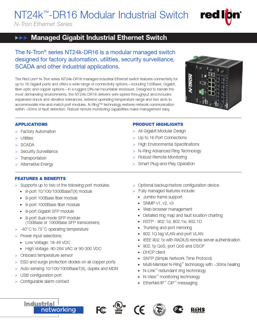
The N-Tron ® series NT24k-DR16 is a modular managed switch designed for factory automation, utilities, security surveillance, SCADA and other industrial applications.The Red Lion ® N-Tron series NT24k-DR16 managed industrial Ethernet switch features connectivity for up to 16 Gigabit ports and offers a wide range of connectivity options—including 100Base, Gigabit, fiber optic and copper options—in a rugged DIN-rail mountable enclosure. Designed to handle the most demanding environments, the NT24k-DR16 delivers wire-speed throughput and includes expanded shock and vibration tolerances, extreme operating temperature range and two slots to accommodate mix-and-match port modules. N-Ring™ technology restores network communication within ~30ms of fault detection. Robust remote monitoring capabilities make management easy.FEATURES & BENEFITS>Supports up to two of the following port modules:• 8-port 10/100/1000BaseT(X) module • 8-port 100Base fiber module • 8-port 1000Base fiber module • 8-port Gigabit SFP module• 8-port dual mode SFP module(100Base or 1000Base SFP transceivers) >-40oC to 75oC operating temperature >Power input selections:• Low Voltage: 18-49 VDC• High Voltage: 90-264 VAC or 90-300 VDC >Onboard temperature sensor>ESD and surge protection diodes on all copper ports >Auto-sensing 10/100/1000BaseT(X), duplex and MDIX >USB configuration port >Configurable alarm contactNT24k ™-DR16 Modular Industrial SwitchN-Tron Ethernet SeriesPRODUCT HIGHLIGHTS >All Gigabit Modular Design >Up to 16 Port Connections >High Environmental Specifications >N-Ring Advanced Ring Technology >Robust Remote Monitoring >Smart Plug-and-Play OperationAPPLICATIONS >Factory Automation >Utilities >SCADA>Security Surveillance >Transportation >Alternative Energy >Optional backup/restore configuration device >Fully managed features include:• Jumbo frame support • SNMP v1, v2, v3• Web browser management• Detailed ring map and fault location charting • RSTP - 802.1d, 802.1w, 802.1D • Trunking and port mirroring• 802.1Q tag VLAN and port VLAN• IEEE 802.1x with RADIUS remote server authentication • 802.1p QoS, port QoS and DSCP • DHCP client• SNTP (Simple Network Time Protocol)• Multi-Member N-Ring ™ technology with ~30ms healing • N-Link ™ redundant ring technology • N-View ™ monitoring technology • EtherNet/IP ™ CIP ™ messagingcompliantSWITCH PROPERTIESNumber of MAC Addresses: 16KAging Time: ProgrammableLatency (typical): 1.6 μsSwitching Method: Store & ForwardMTBF: >1 million hoursPOWER INPUT OPTIONSSelect one:Low Voltage: 18-49 VDCHigh Voltage: 90-264 VAC or 90-300 VDCInput Current (max): 1.52A @ 24VDCInput Current (max): 580mA @120 VAC/300mA @ 124VDC BTU/hr: 125 @ 24VDCBTU/hr: 268 @ 120VAC/127 @ 124VDC CONNECTORS10/100/1000BaseT(X): Up to 16 RJ45 copper ports100BaseFX: Up to 16 SC or ST fiber ports1000BaseGX: Up to 16 SC fiber ports100BaseSX/LX SFP: Up to 16 LC fiber ports1000BaseGX SFP: Up to 16 LC fiber ports RELIABILITYMTBF: >1 million hoursNETWORK MEDIA10BaseT: ≥Cat3 cable100BaseTX: ≥Cat5 cable1000BaseT: ≥Cat5 cable100BaseFX, 1000BaseSX Multimode: 50-62.5/125μm 100BaseFXE, 1000BaseLX Singlemode: 7-10/125μm RECOMMENDED WIRING CLEARANCEFront and Top: 4” (10.2 cm)CERTIFICATION & COMPLIANCEProduct Safety:Class I, Division 2, Groups A, B, C and D hazardous locations UL508 ANSI/ISA 12.12.01-2012CAN/CSA-C22.2 No. 14CAN/CSA-C22.2 No. 213-M1987Emissions: FCC Title 47, Part 15, Radio Frequency Devices, Subpart B ANSI C63.4-2009; Industry Canada ICES-003EN 55011; EN 61000-6-4 (radiated and conducted)Immunity: EN 61000-3-2; EN61000-3-3; EN 61000-6-2; IEC 61000-4-2 (ESD); IEC 61000-4-3 (RFAM); IEC 61000-4-4 (EFT); IEC 61000-4-5(SURGE); IEC 61000-4-6 (RFCM); IEC 61000-4-8 (PFMF); IEC 61000-4-11 (VDI)Other: ABS Type Approval for Shipboard Applications;EMC Directive 2004/108/EC; GOST-RENVIRONMENTALOperating Temperature: -40˚ C to 75˚ COperating Humidity: 5% to 95% (Non Condensing)Operating Altitude: 0 to 10,000 ft.Shock: 50g @ 10msVibration/Seismic: 30g, 10-200 Hz, triaxialMECHANICALCase DimensionsHeight: 5.97” (15.20 cm)Width: 6.78” (17.22 cm)Depth: 4.59” (11.65 cm)Weight (maximum): 6.4 lbs (2.9 kg)Mount: DIN railDIMENSIONSAll specifications are subject to change. Consult the company website for more information.ORDERING GUIDEw w w.r e d l i o n.n e t Connect. Monitor. Control.Americas*****************Asia-Pacific****************EuropeMiddle EastAfrica******************+1 (717) 767-6511ADLD0332 061015 ©2015 Red Lion Controls, I nc. All rights reserved. Red Lion, the Red Lion logo, N-Tron and Sixnet areregistered trademarks of Red Lion Controls, Inc. All other company and product names are trademarks of their respective owners.NT24K-FX8 MODULE - 100 MB FIBER TRANSCEIVERCHARACTERISTICSFiber Mode MM SM SM SMFiber Length2km15km40km80kmTX Power Min-19 dBm-15 dBm-5 dBm-5 dBmRX Sensitivity Max-31 dBm-31 dBm-34 dBm-34 dBmWavelength1310 nm1310 nm1310 nm1550 nmNT24K-GX8 MODULE - GIGABIT FIBER TRANSCEIVERCHARACTERISTICSFiber Mode MM SM SM SMFiber Length550m @50/125μm300m @62.5/125μm10km40km80kmTX Power Min-9.5 dBm-9.5 dBm-5 dBm0 dBmRX Sensitivity Max-17 dBm-20 dBm-23 dBm-24 dBmWavelength850 nm1310 nm1310 nm1550 nmAssumed Fiber Loss 3.5 to 3.75dB/km0.40 dB/km0.40 dB/km0.25 dB/kmLaser Type VCSEL FP DFB DFBNT24K-SFP-DM8 MODULE - SFP 100BASE FIBER TRANSCEIVERCHARACTERISTICSFiber Mode MM SM SM SMFiber Length2km15km40km80kmTX Power Min-19 dBm-15 dBm-5 dBm-5 dBmRX Sensitivity Max-31 dBm-34 dBm-34 dBm-34 dBmWavelength1310 nm1310 nm1310 nm1550 nmAssumed Fiber Loss 3.5 to 3.75dB/km0.40 dB/km0.40 dB/km0.25 dB/kmLaser Type FP FP FP DFBNT24K-SFP-DM8 OR NT24K-SFP8 MODULES- SFP GIGABITFIBER TRANSCEIVER CHARACTERISTICSFiber Mode MM SM SM SMFiber Length550m @50/125μm275m @62.5/125μm10km40km80kmTX Power Min-9.5 dBm-9.5 dBm-2 dBm0 dBmRX Sensitivity Max-17 dBm-20 dBm-22 dBm-24 dBmWavelength850 nm1310 nm1310 nm1550 nmAssumed Fiber Loss 3.5 to 3.75dB/km0.45 dB/km0.35 dB/km0.25 dB/kmLaser Type VCSEL FP DFB DFBAs the global experts in communication, monitoring and control forindustrial automation and networking, Red Lion has been deliveringinnovative solutions for over forty years. Our automation, Ethernet andcellular M2M technology enables companies worldwide to gain real-timedata visibility that drives productivity. Product brands include Red Lion,N-Tron® and Sixnet®. With headquarters in York, Pennsylvania, the companyhas offices across the Americas, Asia-Pacific and Europe. Red Lion ispart of Spectris plc, the productivity-enhancing instrumentation andcontrols company. For more information, please visit .。
SonicWall TZ670 10GbE Next-Generation Firewall说明书

Highlights:• 10 GbE interfaces in a desktop form factor • SD-Branch ready• Secure SD-WAN capability • SonicExpress App onboarding • Zero-Touch Deployment• Single-pane-of-glass-management through cloud or firewall • SonicWall Switch, SonicWave Access Point and Capture Client integration • Built-in and expandable storage • Redundant power • High port density • Cellular failover • SonicOS 7.0• TLS 1.3 support• Groundbreaking performance • High connection count • Fast DPI performance • Low TCOSonicWall TZ670The SonicWall TZ670 is the firstdesktop-form-factor next-generation firewall (NGFW) with 10 Gigabit Ethernet interfaces.Designed for mid-sized organizations and distributed enterprise with SD-Branch locations, the TZ670 delivers industry-validated security effectiveness with best-in-class price-performance. TZ670 NGFWs address the growing trends in web encryption, connected devices and high-speed mobility by delivering a solution that meets the need for automated, real-time breach detection and prevention. The TZ670 is highly scalable, with high port density of 10 ports. It features both in-built and an expandable storage of up to 256GB, that enables various features including logging, reporting, caching, firmware backup and more. An optional second power supply provides added redundancy in case of failure. Deployment of TZ670 is furthersimplified by Zero-Touch Deployment, with the ability to simultaneously roll out these devices across multiple locations with minimal IT support. Built on next-gen hardware, itintegrates firewalling and switching capabilities, plus provides single-pane-of-glass management forSonicWall Switches and SonicWave Access Points. It allows tightSonicOS and Security ServicesThe SonicOS architecture is at the core of TZ NGFWs. TZ670 is powered by the feature rich SonicOS 7.0operating system with new modern looking UX/UI, advanced security, networking and managementcapabilities. TZ670 features integrated SD-WAN , TLS 1.3 support, real-time visualization, high-speed virtual private networking (VPN) and other robust security features.Unknown threats are sent toSonicWall’s cloud-based Capture Advanced Threat Protection (ATP) multiengine sandbox for analysis. Enhancing Capture ATP is our patent-pending Real-Time Deep Memory Inspection (RTDMI™) technology. As one of Capture ATP’s engine, RTDMI detects and blocks malware and zero-day threats by inspecting directly in memory.By leveraging Capture ATP with RTDMI technology, in addition tosecurity services such as Reassembly-Free Deep Packet Inspection (RFDPI), Anti-virus and Anti-spyware Protection, intrusion preventionsystem, Application Intelligence and Control, Content Filtering Services, DPI-SSL, TZ series firewalls stop malware, ransomware and otheradvanced threats at the gateway. ForTZ670DeploymentsSmall to Medium size Business• Save space and money with an integrated gateway security solution with firewalling, switching and wireless capabilities • Reduce complexity and get the business runningwithout relying on IT personnel with easy onboarding using SonicExpress App and Zero-Touch Deployment, and easy management through a single pane of glass • Attain business continuity by providing failover to cellular connectivity • Protect network from attacks with a comprehensive security solution that incorporates VPN, IPS, CFS, AV and much more • Leverage high port density to power on multiple PoE devices such as IP phones and IP cameras • Boost employee productivity by blockingunauthorized access with traffic segmentation and access policiesSonicWall SwitchZero-T ouch Deployment CapableSonicWave Access PointZero-T ouch Deployment CapableCamera IP PhoneLaptopSmartphoneCapture Client Access SecurityEndpoint SecurityDistributed Enterprise with SD-Branches• Enhance customer experience and adapt to the changing business needs by enabling next-gen branch connectivity with SD-Branch • Drive business growth by investing in next-genappliances with multi-gigabit and advanced security features, to future-proof against the changing network and security landscape • Secure networks from the most advanced attacks with advanced security features and automatically block threats on decrypted traffic using protocols such as TLS 1.3• Leverage end-to-end network security withseamless integration of SonicWave access points, SonicWall Switches and Capture Client • Ensure seamless communication as stores talk to HQ via easy VPN connectivity which allows IT administrators to create a hub and spoke configuration for the safe transport of data between all locations • Improve business efficiency, performanceand reduce costs by leveraging TZ670’s hardware and software enhancements, plus features such SD-WAN technology • Scale quickly and effortlessly with SonicExpress App and Zero-Touch Deployment • Ensure business continuity by providing failover to cellular connectivity • Maintain compliance with security features, and leverage built-in and expandable storage to store logs for audit purposesSonicWall TZ670 specifications- WAN X1 and X2 Port LEDs - X0–X7 RJ45 Port LEDs- X8 / X9 SFP/SFP+ Port LEDsSuperSpeed PortsLEDs -Security LED-Storage LEDPower InputConsole PortSonicWall TZ670 specifications, continuedContent Filtering Service (CFS)HTTP URL, HTTPS IP, keyword and content scanning, Comprehensive filtering based on filetypes such as ActiveX, Java, Cookies for privacy, allow/forbid lists Comprehensive Anti-Spam Service YesApplication Visualization YesApplication Control YesCapture Advanced Threat Protection YesDNS Security YesMajor regulatory compliance GS, CB, Mexico DGN notice by UL, WEEE, REACH, BSMI, KCC/MSIP, ANATELTesting Methodologies: Maximum performance based on RFC 2544 (for firewall). Actual performance may vary depending on network conditions and activated services.Threat Prevention/GatewayAV/Anti-Spyware/IPS throughput measured using industry standard Spirent WebAvalanche HTTP performance test and Ixia test tools. Testing done with multiple flows through multiple port pairs. Threat Prevention throughput measured with Gateway AV, Anti-Spyware, IPS and Application Control enabled.VPN throughput measured using UDP traffic at 1280 byte packet size adhering to RFC 2544. All specifications, features and availability are subject to change.BGP is available only on SonicWall TZ400, TZ500 and TZ600.For rack mount, separate rack mount kit available.SonicOS 7.0 Feature SummaryFirewall• Stateful packet inspection• Reassembly-Free Deep Packet Inspection • DDoS attack protection (UDP/ICMP/SYN flood)• IPv4/IPv6 support• Biometric authentication for remote access • DNS proxy• Full API support• SonicWall Switch integration• SD-WAN scalability• SD-WAN Usability Wizard1• SonicCoreX and SonicOS containerization1• Connections scalability (SPI, DPI, DPI SSL) Enhanced dashboard1• Enhanced device view• Top traffic and user summary• Insights to threats• Notification centerTLS/SSL/SSH decryption and inspection• TLS 1.3 with enhanced security1• Deep packet inspection for TLS/SSL/SSH • Inclusion/exclusion of objects, groupsor hostnames• SSL control• Enhancements for DPI-SSL with CFS• Granular DPI SSL controls per zone or rule Capture advanced threat protection2• Real-Time Deep Memory Inspection• Cloud-based multi-engine analysis• Virtualized sandboxing• Hypervisor level analysis• Full system emulation• Broad file type examination• Automated and manual submission• Real-time threat intelligence updates• Block until verdict• Capture ClientIntrusion prevention2• Signature-based scanning• Automatic signature updates• Bi-directional inspection• Granular IPS rule capability• GeoIP enforcement• Botnet filtering with dynamic list• Regular expression matchingAnti-malware2• Stream-based malware scanning• Gateway anti-virus• Gateway anti-spyware• Bi-directional inspection• No file size limitation• Cloud malware database Application identification2• Application control• Application bandwidth management• Custom application signature creation• Data leakage prevention• Application reporting over NetFlow/IPFIX• Comprehensive application signature databaseTraffic visualization and analytics• User activity• Application/bandwidth/threat usage• Cloud-based analyticsHTTP/HTTPS Web content filtering2• URL filtering• Proxy avoidance• Keyword blocking• Policy-based filtering (exclusion/inclusion)• HTTP header insertion• Bandwidth manage CFS rating categories• Unified policy model with app control• Content Filtering ClientVPN• Secure SD-WAN• Auto-provision VPN• IPSec VPN for site-to-site connectivity• SSL VPN and IPSec client remote access• Redundant VPN gateway• Mobile Connect for iOS, Mac OS X, Windows,Chrome, Android and Kindle Fire• Route-based VPN (OSPF, RIP, BGP)Networking• PortShield• Jumbo frames• Path MTU discovery• Enhanced logging• VLAN trunking• Port mirroring (NS a 2650 and above)• Layer-2 QoS• Port security• Dynamic routing (RIP/OSPF/BGP)• SonicWall wireless controller• Policy-based routing (ToS/metric and ECMP)• NAT• DHCP server• Bandwidth management• A/P high availability with state sync• Inbound/outbound load balancing• High availability - Active/Standby withstate sync• L2 bridge, wire/virtual wire mode, tap mode,NAT mode• Asymmetric routing• Common Access Card (CAC) supportVoIP• Granular QoS control• Bandwidth management• DPI for VoIP traffic• H.323 gatekeeper and SIP proxy supportManagement, monitoring and support• Capture Security Appliance (CS a) support• Capture Threat Assessment (CTA) v2.0• New design or template• Industry and global average comparison• New UI/UX, Intuitive feature layout1• Dashboard• Device information, application, threats• Topology view• Simplified policy creation and management• Policy/Objects usage statistics1• Used vs Un-used• Active vs Inactive• Global search for static data• Storage support1• Internal and external storage management1• WWAN USB card support (5G/LTE/4G/3G)• Network Security Manager (NSM) support• Web GUI• Command line interface (CLI)• Zero-Touch registration & provisioning• CSC Simple Reporting1• SonicExpress mobile app support• SNMPv2/v3• Centralized management and reporting withSonicWall Global Management System (GMS)2• Logging• Netflow/IPFix exporting• Cloud-based configuration backup• BlueCoat security analytics platform• Application and bandwidth visualization• IPv4 and IPv6 management• CD management screen• Dell N-Series and X-Series switchmanagement including cascaded switchesDebugging and diagnostics• Enhanced packet monitoring• SSH terminal on UIWireless• SonicWave AP cloud management• WIDS/WIPS• Rogue AP prevention• Fast roaming (802.11k/r/v)• 802.11s mesh networking• Auto-channel selection• RF spectrum analysis• Floor plan view• Topology view• Band steering• Beamforming• AirTime fairness• Bluetooth Low Energy• MiFi extender• RF enhancements and improvements• Guest cyclic quotaNew feature, available on SonicOS 7.0 Requires added subscriptionProductSKUTZ670 with 1-year TotalSecure Essential Edition02-SSC-5640TZ670 with 3-year Secure Upgrade Plus Essential Edition 02-SSC-5660TZ670 High Availability02-SSC-5654ServicesSKUEssential Protection Service Suite - Capture ATP, Threat Prevention, Content Filtering, Anti-Spam and 24x7 Support (1-year)02-SSC-5053Capture Advanced Threat Protection for TZ670 (1-year)02-SSC-5035Gateway Anti-Virus, Intrusion Prevention and Application Control (1-year)02-SSC-5059Content Filtering Service (1-year)02-SSC-5047Comprehensive Anti-Spam Service (1-year)02-SSC-504124x7 Support (1-year)02-SSC-5029AccessoriesSKUSonicWall TZ670/570 Series FRU Power Supply 02-SSC-3078SonicWall TZ670/570 Series Rack Mount Kit02-SSC-3112SonicWall 32GB Storage Module for TZ670/570 Series 02-SSC-3114SonicWall 64GB Storage Module for TZ670/570 Series 02-SSC-3115SonicWall 128GB Storage Module for TZ670/570 Series 02-SSC-3116SonicWall 256GB Storage Module for TZ670/570 Series 02-SSC-311710GB-SR SFP+ Short Reach Fiber Module Multi-Mode No Cable 01-SSC-978510GB-LR SFP+ Long Reach Fiber Module Single-Mode No Cable 01-SSC-978610GB SFP+ Copper with 1M Twinax Cable 01-SSC-978710GB SFP+ Copper with 3M Twinax Cable01-SSC-97881GB-SX SFP Short Haul Fiber Module Multi-Mode No Cable 01-SSC-97891GB-LX SFP Long Haul Fiber Module Single-Mode No Cable 01-SSC-97901GB-RJ45 SFP Copper Module No Cable01-SSC-9791SonicWall SFP+ 10GBASE-T Transceiver Copper RJ45 Module 02-SSC-1874SonicWall Micro USB Console Cable for TZ670/570 Series02-SSC-5173Regulatory model numbersTZ670APL62-0F7About SonicWallSonicWall delivers Boundless Cybersecurity for the hyper-distributed era and a work reality where everyone is remote, mobile and unsecure. By knowing the unknown, providing real-time visibility and enabling breakthrough economics, SonicWall closes the cybersecurity business gap for enterprises, governments and SMBs worldwide. For more information, visit .。
海视光 Hybrid SAN 系统产品说明书
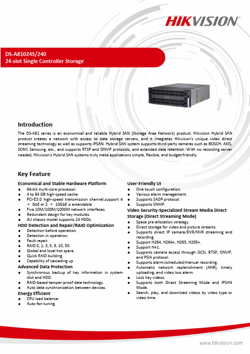
DS-A81024S/24024-slot Single Controller StorageIntroductionThe DS-A81 series is an economical and reliable Hybrid SAN (Storage Area Network) product. Hikvision Hybrid SAN product creates a network with access to data storage servers, and it inte grates Hikvision’s unique video direct streaming technology as well as supports IPSAN. Hybrid SAN system supports third-party cameras such as BOSCH, AXIS, SONY, Samsung, etc., and supports RTSP and ONVIF protocols, and extended data retention. With no recording server needed, Hikvision’s Hybrid SAN systems truly make applications simple, flexible, and budget-friendly.Key FeatureEconomical and Stable Hardware Platform●64-bit multi-core processor.● 4 to 64 GB high-speed cache.●PCI-E3.0 high-speed transmission channel,support 4×GbE or 2 ×10GbE is extendable●Five 10M/100M/1000M network interfaces.●Redundant design for key modules.●4U chassis model supports 24 HDDs.HDD Detection and Repair/RAID Optimization●Detection before operation.●Detection in operation.●Fault repair.●RAID 0, 1, 3, 5, 6, 10, 50.●Global and local hot spare.●Quick RAID building.●Capability of cascading upAdvanced Data Protection●Synchronous backup of key information in systemdisk and HDD.●RAID-based tamper-proof data technology.●Auto data synchronization between devices. Energy Efficient●CPU load balance.●Auto fan tuning. User-Friendly UI●One touch configuration.●Various alarm management.●Supports SADP protocol.●Supports SNMP.Video Security-Specialized Stream Media Direct Storage (Direct Streaming Mode)●Space pre-allocation strategy.●Direct storage for video and picture streams.●Supports direct IP camera/DVR/NVR streaming andrecording.●Support H264, H264+, H265, H265+.●Support N+1.●Supports camera access through iSCSI, RTSP, ONVIF,and PSIA protocol.●Supports alarm/scheduled/manual recording.●Automatic network replenishment (ANR), timelyuploading, and video loss alarm.●Lock key videos.●Supports both Direct Streaming Mode and IPSANMode.●Search, play, and download videos by video type orvideo time.SpecificationNetworkProtocol iSCSI, RTSP, ONVIF, PSIAExternal interfaceUSB 2*USB3.0,1*USB2.0VGA SupportedData network interface 4, 1000M Ethernet interface(4 × GbE or 2 × 10GbE is extendable)MiniSAS interface 1COM 1Management network interface 1, 1000M Ethernet interfaceStorageHDD slot 24HDD information 24*10TBInterface/capacity SATA/1 TB, 2 TB, 3 TB, 4 TB, 6 TB, 8 TB, 10 TB, 12 TB, 14 TB, 16 TBHot-swapping SupportedHDD support RAID(Enterprise Hard Disk)RAID RAID 0, 1, 3, 5, 6, 10, 50,JBOD, Hot-SparePerformanceDirect Streaming Mode: video (2Mbps) + picture512-chHardwareStructure Controller StructureProcessor 64-bit multi-core processorCache 4 GB (extendable to 64GB)Storage ManagementDisk management Disk inspection, alarm and repairLogical volume management iSCSI volume, video volume managementRecording ManagementRecording mode Timing recording, manual recording, alarm recordingVideo protection Lock key video, N+1 service protection, ANR, video loss detection and alarm Searching mode Search by time and eventDownloading mode Quick download, batch download, download by segment, download by merging Device MaintenanceManagement mode Web-based GUI, serial port CLI, centralized management of multiple devices Alarm mode Sound, light, email, message, web pageLog downloading Download on web pageHDDHDD Model Hikvision,HK7216AH,16T; Hikvision,HK7210AH,10T; Hikvision,HK728TAH,8T; Hikvision,HK726TAH,6T; Hikvision,HK724TAH,4T;GeneralPower supply Redundant 550W Consumption(with HDDs) Working: ≤ 480Environment temperature Working: +5 °C to +40 °C (41 °F to 104 °F);Storing: -20 °C to +70 °C (-4 °F to +158 °F)Humidity Working: 20% to 80%RH (non-condensing/frozen); Storing: 5% to 90%RH (non-condensing/frozen)Chassis 4U (19-inch height)Dimensions(W × D × H) 484 x 684 x 174 mm (19.1 x 26.9 x 6.9 in) Weight (without HDDs) 29kgTypical Application⏹Physical InterfaceNo.Description No.Description1Power module7COM2VGA interface8FN button3USB interface9Power switch4USB interface10Management LAN interface5LAN interface 1 to 411RS-232 interface6SAS interface⏹Available ModelDS-A81024S/240Dimension。
云计算HCIP习题库(含参考答案)

云计算HCIP习题库(含参考答案)一、单选题(共52题,每题1分,共52分)1.在 FusionCompute 中,已切换为 SR-IOV 模式的网卡可以更换为不支持 SR-IOV 模式的网卡。
A、TRUEB、FALSE正确答案:A2.在华为桌面云中,制作模板时,完整复制、快速封装、链接克隆的模板,都需要加入域。
A、TRUEB、FALSE正确答案:B3.以下哪一项内存复用技术可以回收虚拟机暂时不用的物理内存,分配给需要复用内存的虚拟机?A、内存置换B、内存共享C、内存透明大页D、内存气泡正确答案:D4.FusionCompute 支持使用 VMDK 类型磁盘文件导入,以创建新的虚拟机。
A、TRUEB、FALSE正确答案:B5.在 FusionCompute 中,以下关于虚拟机模板的描述,不正确的是?A、虚拟机克隆为模板:克隆完成后,该虚拟机仍可正常使用。
B、模板克隆为模板:克隆完成后,原模板仍存在。
C、虚拟机转为模板:转换后,该虚拟机仍可正常使用。
D、导入模板:可调整部分参数设置,使其与本地虚拟机模板稍有不同。
正确答案:C6.在 FusionCompute 中,CPU 资源以什么单位衡量?A、THZB、线程数C、核数D、GHz正确答案:D7.FusionCompute 中端口聚合会使用什么进行负荷分担?A、源目 MACB、源目 IPC、源目端口D、源目端口组正确答案:A8.华为桌面云系统本地备份方式产生的备份文件存放路径是?A、/var /huawei/vdes ktop/backupB、/backupC、/var/backupD、/var /vdesktop/backup正确答案:D9.对于采用 GPU 硬件虚拟化技术的桌面虚拟机,一个 vGPU 最多可以绑定给几个桌面虚拟机使用?A、32 个B、无数个C、1 个D、3 个正确答案:C10.下列关于 IMC 的功能描述正确的是?A、IMC 配置可以确保集群内的主机向虚拟机提供相同的 CPU 功能集,即使这些主机的实际 CPU 不同,也不会因 CPU 不兼容而导致迁移虚拟机失败。
大数据HCIA模拟考试题(含答案)

大数据HCIA模拟考试题(含答案)一、单选题(共40题,每题1分,共40分)1、RDD有Transformation和Action算子,下列属于Action算子的是?A、saveAsTextFileB、reduceByKeyC、mapD、filter正确答案:A2、下面关于ZooKeeper描述错误的是()A、一条消息被一半以上的server接收,他将写入磁盘B、ZooKeeper的节点数必须是奇数个C、消息更新只有成功和失败,没有中间状态D、客户端发送的更新会按照他们发送的顺序被应用正确答案:B3、在规划FuskmlnsightHD集群时候,如果客户用于功能测试,对性能没有要求,节约成本的情况下,可以采用管理节点、控制节点、数据节点合一部署,最少需要多少节点?A、2B、3C、4D、5正确答案:B4、FusionInsightHD部署时,同一集群内的Flumeserver节点建议至少部署几个?A、1B、2C、3D、4正确答案:B5、FusionlnsightHadoop集群中,在某节点上通过df-hT查询,看到的分区包含以下几个:/var/log/srv/BigData/srv/BigData/hadoop/data5/srv/BigData/so lr/solrserver3/srv/BigData/dbdataom这些分区所对应磁盘最佳Raid 级别的规划组合是?A、Raid0Raid1Raid0Non-Raid1B、Raid1Raid1Non-RaidNon-RaidRaid1C、Raid0Raid0Raid0Raid0Raid0D、Non-RaidNon-RaidNon-RaidNon-RaidRaid1正确答案:B6、FusionlnsightHDManager界面Hive日志收集,那个选项不正确?A、可指定实例进行曰志收集,比如指定单独收集MetaStore的曰志B、可指定时间段进行日志收集,比如只收集2016-1-1到2016-1-10的日志C、可指定节点IP进行曰志收集,例如仅下载某个IP的曰志D、可指定特定用户进行曰志收集,例如仅下载userA用户产生的曰志正确答案:D7、关于Kafka磁盘容量不足的告警,对于可能的原因以下分析不正确的是?A、用于存储Kafka数据的磁盘配置(如磁盘数目、大小等),无法满足当前业务数据流量,导致磁盘使用率达到上限B、数据保存时间配置过长,数据累积达到磁盘使用率上限C、业务规划不合理,导致数据分配不均匀,使部分磁盘达到使用率上限D、Broker节点故障导致正确答案:D8、FusionInsightHD系统中,flume数据流在节点内不需要经过哪个组件?()A、sinkB、topicC、SourceD、Channel正确答案:B9、HDFS中的主备仲裁,是由哪个组件控制的?A、ZooleeperFailoverControllerB、NodeManagerC、ResourceManagerD、HDFSClient正确答案:A10、关于HBase中HFile的描述不正确的是?A、一个HFile属于一个RegionB、一个HFile包含多个列族的数据C、一个HFile包含多列数据D、一个HFile包含多行数据正确答案:B11、FusionInsightHD中loader从SFTP服务器导入文件时,不需要做编码转换和数据转换且速度最快的文件类型是以下哪项?()A、sequence_fileB、text_fileC、binary_fileD、graph_file正确答案:C12、关于FusionInsightHD中Loader作业描述正确的是?A、Loader将作业提交到Yarn执行后,如果此时Loader服务出现异常,则此作业执行失败。
- 1、下载文档前请自行甄别文档内容的完整性,平台不提供额外的编辑、内容补充、找答案等附加服务。
- 2、"仅部分预览"的文档,不可在线预览部分如存在完整性等问题,可反馈申请退款(可完整预览的文档不适用该条件!)。
- 3、如文档侵犯您的权益,请联系客服反馈,我们会尽快为您处理(人工客服工作时间:9:00-18:30)。
I.J. Information Technology and Computer Science, 2018, 2, 33-44Published Online February 2018 in MECS (/)DOI: 10.5815/ijitcs.2018.02.04Phoenix: A Framework to Support Transient Overloads on Cloud Computing Environments Edgard H. Cardoso Bernardo1, Wallace A. Pinheiro2, Raquel Coelho G. Pinto11Instituto Militar de Engenharia (IME), Rio de Janeiro, RJ, Brazil,2Centro de Desenvolvimento de Sistemas (CDS), Brasília, DF, BrazilE-mail: edgardbernardo@.br, wallace@.br, raquel@ime.eb.brReceived: 30 September 2017; Accepted: 17 November 2017; Published: 08 February 2018Abstract—This paper aims to present a computational framework capable of withstanding the effects produced by transient overloads on physical and virtual servers hosted on cloud computing environment. The proposed framework aims at automating management of virtual machines that are hosted in this environment, combining a proactive strategy, which performs load balancing when there is not overload of physical and/or virtual machines with a reactive strategy, which is triggered in the event of overload in these machines. On both strategies, it is observed the service level agreement (SLA) established for each hosted service according to the infrastructure as a service (IaaS) model. The main contribution of this paper is the implementation of a computational framework called Phoenix, capable of handling momentary overloads, considering the CPU, memory and network resources of physical and virtual machines and guaranteeing SLAs. The results demonstrate that Phoenix framework is effective, and it has outstanding performance in handling overloads virtual machine network, which has achieved the isolation of momentary overload on the physical machine preventing the propagation of their effects on the cloud.Index Terms—Cloud Computing, Resource Management, Load Balancing, Distributed Systems, Virtual Machine.I.I NTRODUCTIONCloud computing can be defined as a type of parallel and distributed system, built from a collection of virtualized and interconnected computers. These are available dynamically as unified resources having their services based on services levels [1, 3].The cloud service model has three types of service model; Software as a Service (SaaS), Platform as a Service (PaaS) and Infrastructure as a Service (IaaS). For SaaS service model, it is available software or applications that the customer can subscribe and access from the cloud.The PaaS offers to the customer a suitable development platform with tools to be able to support their needs.The IaaS is bottom layer of cloud the reference model. This service model provides the resources (with computing power: CPU, memory, storage and network) and abstract into numbers of virtual machines for the cloud subscribers [18].In cloud computing environments, there are big sets of Physical Machines (PMs) containing Virtual Machines (VMs). This combination allows multifaceted and dynamic aspects of cloud computing and requires efficient and optimized techniques for resource provisioning and load balancing. For this purpose, cloud monitoring is required to identifying overutilized and underutilized of PMs which hosting VMs [14]. Mechanisms of vertical and horizontal scaling, described by [2], should ensure an elastic behaviour to these environments [4]. However, even in a virtualized environment, provided by cloud computing, threatens, extremely harmful to the functionality of services, can emerge: instability periods, failed related to storage of data, performance reduction, among others, which can compromise seriously the credibility of some service providers.The Resource Assignment Strategy (RAS) is based on the integration of activities performed by the cloud provider to allocate resources available in this environment to meet the needs of the hosted applications. It provides the type and amount of resources required at the time and for the time required for each user application to complete its work [16].Transient overloads as flash crowds [5], which can demand all existent computational resources in a short period of time, still may cause an eventual interruption of service, which can lead to a break of contract between service providers and their clients. These contracts can stipulate, for example, cloud data center resources (e.g. CPU, memory, network bandwidth and storage) may be allocated based on the reduction of energy usage as on satisfaction of Quality of Service (QoS) requirements specified by users via SLAs.Thus far, in cloud environment, there are often situations of not demand contrast with peak demands for resources this way, good Resource Allocation Strategy (RAS) is required. So, an optimal RAS should avoid resource contention, scarcity of resources, resource fragmentation and over provisioning [16].This paper proposes a framework called Phoenix that combines set of proactive and reactive strategies in orderto support transient overload caused by flash crowds using a virtualized environment in cloud computing. Load balancing of VMs in PMs is used as a proactive strategy, avoiding premature overload of these machines. However, once the limits established to PMs are reached too fast, the reactive strategy is triggered to find the necessary resources.After experiments, we conclude that the proposed algorithms automatically support overloading of resources. The proposal has proven to be appropriate to the reality of cloud computing data centers, ensuring the dynamic allocation of resources in the cloud.This paper is organized as follows: Section II presents related work, Section III presents proposed solution, Section IV discusses about the overload experiments and finally Section V provides remarks and future research directions.II.R ELATED W ORKSIn cloud environment, there are often situations of peak demands and non-demand for resources. Hence to match with these uncertain demands for resources, good Resource Allocation Strategy is required. It provides an on-demand services by means of dynamic allocation of resources to provide reliable and high available services to the users.Thus, to balance the level of supply and demanding of resources, Resource Allocation Strategy must be able to handle the following issues regarding the resources: Contention, Fragmentation, Over-provisioning and under-provisioning. [15]. Those issues have been investigated in the literature. In addition, it is necessary to take into account contracts between service providers and customers, such as SLAs. The above approaches present some ways for problem mitigation.Zhen et. al [25] use the predictive load model to predict future uses of application resources accurately. But they used this method only in dynamic VM consolidation. If the expected future load of a server indicates an underuse of resources, the VM migration will not occur. This reduces the number of VM migration as well as the number of false hotspot events. Zhen et. al [25] also introduced the concept of "skewness" to improve the overall use of server resources. During migration, this server is used as a target, which ability can be reduced by accepting the migrant VM. Unlike the one proposed in [25], Phoenix considers a server that the server is overloaded when the server's cumulative load is greater than the parametrized upper limit. This can prevent unnecessary migrations from being initiated due to a momentary increase in resource utilization. The Phoenix uses a mechanism that accumulates historical data of the measurements of each resource value and operates a configurable delay where the value considered is an accumulated of the measured values as described by Siberschatz et al. [17]. By doing this, is avoided that resource utilization peaks are considered as overloads this mechanism is a cumulative load of the PM server or VM. In addition, the proposed architecture uses the concept of distance from the cluster balance range to find a target host when evaluating migrations.Khanna et al. [27] monitor the resources (CPU and memory) of physical and virtual machines. They proposed the idea of fixed threshold value that would limit the maximum use of resources. If a feature exceeds a predefined threshold and there is a chance of SLA violation, then the system migrates a Virtual Machine (VM) to another Physical Machine (PM). Phoenix, in addition to considering the network resource, uses a similar principle to perform the migration, the lower cost VM being chosen to be removed from the PM. In addition, when the network overload occurs, the migration of the unaffected machines is done, starting with the lowest cost.Anton et al. [28] proposed algorithms for efficiently mapping the energy efficiency of virtual machines to suitable cloud resources. They created different methods of VM selection, such as "minimization of migration policy," "higher potential growth policy," and "random policy of choice" to choose a migration-specific VM. The authors suggested that it is not a wise decision to keep the usage limit set because the workload is changing continuously. In their subsequent article [33], the authors proposed Inter Quartile Range (IQR) and Median Absolute Deviation (MAD) methods to dynamically find the upper limit of a server.According to Anton et al. [27], if the current host load is greater than the upper bound, then it is considered overloaded. The concept of adaptive boundary works much better than the static threshold in the dynamic cloud environment. They also proposed methods such as Local Regression (LR) and Robust Local Regression (LRR) to predict the future load, but in those methods, hosts are considered overloaded only when the intended use is greater than or equal to 100%. Phoenix considers a overloaded PM when current and future load is greater than parameterized upper limit. This can prevent unnecessary migrations from being initiated due to a momentary increase in resource utilization. We use an exponential moving average based prediction technique [5] which is a cumulative charge of the PM server or VM. Wood et al. [7] introduced a system called Sandpiper to automate the task of detecting overloads and determining a new mapping of physical resources to virtual resources and initiating the necessary migrations in a virtualized data center. To ensure that a small transient peak does not trigger unnecessary migrations, an overhead is only marked if the thresholds or SLAs are exceeded for a sustained time. The migration occurs only when at least k of the most recent observations, as well as the next predicted value exceeds a threshold. The limit that is considered in this article is static. The authors use the automatic regression method to calculate the next predicted value. After a hotspot detected, the VM whose maximum volume-to-size (VSR) ratio is migrated. When the system load is high, it is not possible to migrate to VM with the highest VSR. In this case, the VM swap occurs to reduce the load on the cache. According to Zhen et al. [27] this strategy will not work effectively duringthe system's peak load, since switching VMs will increase the migration load unnecessarily. Phoenix uses a similar method to identify overhead, but being in contrast with Wood et al. [7], Phoenix migrates to lower-cost VM in the case of CPU or RAM overhead. In the case of network overload, the VM that is overloaded remains in the source PM while the other VMs, in descending order of volume, are migrated to PMs that are capable of receiving them.The VOLTAIC (V olume Optimization Layer to Assign Cloud) system, as described by Carvalho and Duarte [6], functions as an autonomous resource manager for the cloud and aims to increase the quality of service provided to customers and avoid wasting computational resources [ 6]. This system uses controllers based on fuzzy logic to detect the saturation of PMs and proposes algorithms to reciprocate VM automatically, considering VM usage profiles and availability of resources in each PM. VOLTAIC is compatible with most platforms that support the libvirt library, such as: Xen [8], VMWare [9] and KVM [11].Norman et al. [30] developed a management algorithm for dynamic allocation of virtual machines to physical servers. The algorithm is based on measuring historical data, predicting future demand and remapping VMs to PMs, and it is subsequently referred to as Measure-Forecast-Remap (MFR). Time series forecasting techniques and bin packaging heuristics are combined to minimize the number of PMs required to support a workload. In this algorithm, the prediction method is used to find the resource demand of individual VMs. Based on predicted values, VMs are organized in descending order and the first-fit heuristic is used to migrate the VMs. Conversely, Phoenix is a computational architecture capable of to support transient overloads, such as flash crowds, in cloud computing environments. Therefore, Phoenix uses an algorithm whose automatically manage PMs and VMs, being able to monitoring resources (CPU, RAM, Network) of PMs and VMs automatically, manage VM hosting and handling in PMs, detect and load transient overloads taking into consideration the SLAs and finally, it is also able to perform load balancing between PMs. To detect overloads, the Phoenix uses a detector that has a configurable trigger that establishes the limit of use for each PM feature. To measure the resources of the PMs and VMs it is used a mechanism that accumulates historical data of the measurements of each resource value and operates a configurable delay where the value considered is an accumulated of the measured values, as described by Siberschatz et al. [17]. By doing this, is avoided that resource utilization peaks are considered as overloads. Based on this value, considered decisions are made that result in the movement of the VM, either to treat a PM overload, the load balancing or even the identification of the VM overload. As for movements of the VMs, these are based on the increasing order of the momentary use of the resources. For this purpose, the volume of use of the resources is calculated each VM. Based on the obtained values, a VM list in ascending order of volume is established. From this list, VMs are moved as PMs. The PMs receives VM according to their capacity and it situation in relation to average capacity of t cluster’s PMs. Kochut and Beaty [26] proposed an analytical model of VM migration that provides estimates of the expected gain in response time due to a migration decision. The model is based on the M/M/1 queuing model and considers the characteristics of a virtualized environment, such as migration costs and overhead, due to the additional consumption of resources. This VM is selected for migration that minimizes system response time. Although it does not use the same algorithm, Phoenix uses the predictive model based on threshold of hotspot and or load balancing using cluster equilibrium range. Arzuaga et. al. [31] presented a new metric that captures the load of the physical servers according to the loads of the resident VMs. The load unbalance is measured by using this metric. The proposed load-balancing algorithm follows a greedy approach. The VM that will produce the greatest imbalance metric improvement is selected for migration. In addition to load balancing, the VM migration performed by Phoenix will also make the system more efficient by making the systems more resilient to transient overloads since all post-balancing PMs will be within the cluster's equilibrium range. In this way, all PMs will have similar conditions to withstand transient overloads.Andreolini et al. [32] proposed a new management algorithm to decide on VM overloads in a cloud environment. Instead of the traditional threshold method, the authors used the load profile evaluated through a cumulative sum-based stochastic model. This method eliminates unnecessary VM migrations due to the momentaneous increase in load. The traditional best-fit bin packing algorithm is used for reallocation of the selected VM. Phoenix also eliminates unnecessary VM migrations by using a mechanism that accumulates historical data of the measurements of each resource value and operates a configurable delay where the value considered is an accumulated of the measured values as described by Siberschatz et al. [17]. By doing this, is avoided that resource utilization peaks are considered as overloads. In addition, Phoenix also performs load balancing and PM isolation caused by overloading network beyond the SLA threshold, possibly because it is Flash Crowd or even a DDoS.III.P ROPOSED S OLUTIONPhoenix is a framework to deal with transient overload, such as flash crowds, in cloud computing environments. This framework automatically manages PMs and VMs and it is applicable to the model of Infrastructure as a Service (IaaS) [3].Phoenix framework executes the following activities: monitors resources of PMs and VMs automatically, manages movement and hosting of VMs, detects and supports transient overloads taking into account SLAs, and executes the load balance among PMs. Phoenix framework, showed in Fig.1, is composed of a series ofcomponents that support three main modules: Monitor, Analyzer and Configurator(Migrator). Phoenix Admin Interface helps the administration of these modules, providing an interface that shows all parameters monitored by the framework. The components of Phoenix framework are detailed as follows:Fig.1. Phoenix FrameworkPM i– represents each PM in the framework. PMs host services provided by the cloud. PM1 up to PM n-1 compose the cluster of machines that hosts IaaS services and has its resources managed by the framework. While PM hosts the Analyzer module, the other machines host the Monitor and Configurator modules.VM i–represents each VM in the framework. VMs execu te clients’ applications.Requisitions Network–corresponds to the network infrastructure where users do requisitions to services hosted in VMs.Control and Migration Network - corresponds to the network infrastructure where PMs exchange messages about their status and where VMs are moved (migrated). Thus, this network is dedicated to the management of the framework.Monitor Module –is responsible for gathering resources information (use of network bandwidth, CPU processing and memory usage) from PMs and VMs, registering also the percentage of using (on average) of these resources.Analyzer Module– analyzes relevant events generated by the Monitor module and evaluates the necessity of migrate VMs. This migration can be caused by: overload of PM resources, overload of VM resources, or unbalanced load considering three factors, network bandwidth, CPU processing and memory usage. Once a relevant event happens, the Analyzer module sends a request to the Configurator module.Hypervisor–is responsible for creating, moving and destroying VMs, receiving requests directly from the Configurator module.Virtualization API–is provided by libvirt library. This API is related to resources virtualization and it supports different hypervisors, including KVM that was chosen as virtualization platform to implement the proposed framework.Configurator Module–receives moving requests from the Analyzer module and uses the Virtualization API to migrate VMs. It informs the Monitor module when a VM migration is concluded. The Configurator also allows the use of different strategies of migration, defined by the Analyzer module.Log Files– store information about resources used by machines related to relevant events in different moments of the day, as well as messages exchanged by the framework modules. Each Monitor has a log file. Configuration File–stores information about the limits proposed to each VM and PM, based on SLA established between the service provider and its clients. As the framework adopts a Black-box approach, the monitoring is made externally to VMs and PMs. Another aspect to be highlighted is that the framework can use different hypervisors.A. Proposed Solution OperationPhoenix operation was inspired on OODA loop [11]. There is a strong similarity between OODA loop phases and the process executed by the framework, such as: observation of (machines) status, orientation (based on events), planning and decision about actions to be taken and, finally, execution of the necessary actions. After this, the loop is restarted. The dynamic behaviour of Phoenixis schematically represented in Fig.2.Fig.2. Functioning of PhoenixThe events observed by Monitor module are described as follows:Overload of VM Network–it indicates that the percentage of network bandwidth usage is higher than the predicted in SLA. The message used by Monitor to indicates this event is: OVERNETVM.Overload of PM–it indicates that the percentage of use of CPU, memory or network bandwidth is higher than an established limit (typically it is set to 90% of PM capacity, allowing some time of reaction, before the machine full capacity be reached). The message used by Monitor to indicates this event is: OVERLOADPM. Relevant Event– it denotes some significant variation related to the PM status. In this case, it may be necessary to execute a load balance, depending on the comparison among PM load, the average load of all PMs and some configurable variation (that can be set in Configuration File). One or more VMs should be moved to other(s) PM(s), in order to allow the load balance. The message used by Monitor to indicates this event is: RELEVANT_EVENT.Reachability of VM SLA– it represents that an SLA related to the usage of CPU, memory or network bandwidth was reached. Probably, a new SLA should be established between the service provider and the client, in order to allow the client VM to support the load. The message used by the Monitor to indicate this event is: OVERLOADVM.One additional message created by Monitor is MONITOR_INFO used to indicate beginning of the monitoring operations or restart after a migration.The monitor only sends messages in the situations indicated by these events, in order to minimize the number of messages generated.Algorithm 1 demonstrates the main actions executed by Monitor module based on monitored events. The details about the functions used in the Algorithm 1 are described after the algorithm.Input: start_Monitor/stop_MonitorOutput:info_overnetvm(vm_info)/info_overloadvm(vm_info)/info_overloadpm(pm_info)/info_relevant_event(pm_info)Function Monitor {WHILE stop_Monitor = 'No'get_pm_info()pm_CPU=calculate_accu(pm_info, ‘CPU’)pm_MEM=calculate_accu(pm_info, ‘MEM’)pm_NET=calculate_accu(pm_info, ‘NET’)list_vm=get_vm_info()WHILE list_pm NOT EQUAL '' ''pm_CPU=calculate_accu(pm_info, ‘CPU’)pm_MEM=calculate_accu(pm_info, ‘MEM’)pm_NET=calculate_accu(pm_info, ‘NET’)WHILE list_vm NOT EQUAL '' ''vm_CPU=calculate_accu(vm_info,’CPU’) vm_MEM=calculate_accu(vm_info,’MEM’)vm_NET=calculate_accu(vm_info,’NET’)IF vm_net > limit_vm_NETSEND TOAnalyzer(info_overnetvm(vm_info))ELSE IF vm_CPU > limit_vm_CPU ORvm_mem > limit_vm_MEMSEND TO Analyzer(info_overloadvm(vm_info))END WHILEIF (pm_CPU > limit_CPU OR pm_MEM >limit_MEM OR pm_NET > limit_NET)SEND TO Analyzer(info_overloadpm(pm_info))ELSEIF ((pm_CPU > earlier_pm_CPU +relevant_variation ORpm_CPU < earlier_pm_CPU –relevant_variation)OR(pm_MEM > earlier_pm_MEM +relevant_variation ORpm_MEM < earlier_pm_MEM –relevant_variation)OR(pm_NET > earlier_pm_NET+relevant_variation ORpm_NET < earlier_pm_NET –relevant_variation))ealier_pm_CPU = pm_CPUearlier_pm_MEM = pm_MEMearier_pm_NET = pm_NETSEND TO Analyzer(info_relevant_event(pm_info))END IFEND IFEND WHILEEND WHILE}The get_pm_info()function obtains information about the resources (CPU, memory and network) of PMs.The get_vm_info()function obtains a list of all VMs and information about their resources (CPU, memory and network). The information of each VM is stored in a variable named vm_info.To avoid transient values of CPU, memory and network bandwidth, we proposed the use of the calculate_accu function. It calculates the accumulated value of each resource considering a reduction factor according to Silberschatz et al. [17]. It is expressed by the equation (1):() (1) Where:∙N i+1- is a prediction for the next instantaneous value to be captured.∙μ - is a constant with a value expressed between 0 and 1 (0 < μ < 1), which expresses how much thesnapshot value will be taken into consideration forcalculating the average. It serves as a reducer thatwill allow a greater or lesser lag in detection of anoverload.∙ - is the captured value of use of the resource in percentage in iteration i.∙N i - is the accumulated value of use of the previous iteration feature.The info_overnetvm function informs if the network of a VM is overload.The info_overloadvm function returns if the limit given to CPU, memory or network bandwidth of a VM is reached.The info_overloadpm function informs if the limit given to CPU, memory or network bandwidth of a PM is reached.The info_relevant_event function returns if a defined variation of CPU, memory or network of a PM was reached.The Analyzer module begins when it receives messages from the Monitor modules. It is composed of the following sub-modules: Resource Manager, Decision Maker and Migration Manager.The Resource Manager sub-module is responsible for receiving all messages from the Monitor modules. After this, it calculates the volume and cost of migrating each VM, the load of each PM and the average load of the cluster composed of all PMs. All this information and the original messages sent by monitors are then repassed to the Decision Maker sub-module. If it decides that migrations are necessary, it informs this decision to the Migration Manager sub-module.Therefore, The Analyzer, through the Decision Maker sub-module,evaluates the information related to VMs and PMs. A set of rules is used to infer actions to be taken by the framework. If it is confirmed that the limits of overload related to a machine (VM or PM) were reached or if it is necessary to balance the cluster, the framework will call the suitable action to deal with the situation. The actions are triggered obeying a priority, depending on the event impact. Our analysis indicates that the following ordering of actions should be obeyed:(1) Treat Overload of VM (when it receives data from the info_overnetvm function),(2) Treat Overload of PM (when it receives data from the info_overloadpm function),(3) Treat Relevant Event (when it receives data from the info_relevant_event function), and(4) Treat Reachability of VM SLA (when it receives data from the info_overloadvm function). The next subsections will detail each action taken by Analyzer module.A.1. Action to Treat Overload of VMThis action is quite important because most current hypervisors, such as Xen [8] and KVM [10] do not limit the network bandwidth usage. Therefore, it can jeopardize a PM that support a VM suffering, for instance, a flash crowd event. In this case, all others VMs hosted in this PM can also be affected.We propose a strategy to deal with a VM that consumes a network bandwidth higher than the established in SLA. This VM should be kept in its original PM while others VMs should be migrated. Thus, if it is necessary, this VM is isolated in one PM ensuring its SLA. The others VMs can continue working in others PMs, having also their SLAs protected.In this process, it is important to follow an ordering of VMs to be migrated. The VMs are sorted in order of increasing migration cost. The concept used in this work was defined in [7]. The idea is to release the resources as fast as possible, migrating the lower cost machines first. Regarding the candidate PMs to receive VMs, we propose to prioritize PMs that have the lower load values taking as reference the cluster average load. This procedure aims to keep the cluster as balanced as possible (and, consequently, minimizing the number of migrations).The cluster average load is expressed as the average of real values obtained of CPU, memory and network bandwidth usage. We propose that the administrator of the architecture should define a suitable weight to each one of these attributes, prioritizing what is more important depending on the architecture resources. The equation (2) that defines the Cluster Average Load (CAL) is:(( eig t )( eig t )( eig t )( eig t eig t eig t ))(2) Fig.3 presents a simulation of Phoenix behavior when a VM consumes all network bandwidth of a PM. It also shows the network usage (percentage) of three PMs (PM1,。