P2技术规格书
RG-AC系列无线控制器RGOS 10.4(1b19)p2版本WEB管理手册(V2.0)

13
AC WEB 管理配置
图表 19 配置说明 限速信息:指定用户的上下行速率的限制情况。
图表 20 限速信息 流量走势:指定用户最近 24 小时的总体流量走势。
1.3.3.4.1 流氓AP
图表 23 流氓 AP 配置说明: 显示系统扫描到的流氓 AP 信息。
图表 12 系统日志 配置说明: 显示系统日志,输入需要查询的关键字可以查询匹配的日志记录。 1.3.3.2 AP信息 通过菜单项“AP 信息”使用该功能。
11
AC WEB 管理配置
图表 13 AP 信息 配置说明: 显示 AP 的概览信息。点击“详情”,可以显示指定 AP 的射频信息、流量走势、详细信息和连 接历史。点击“编辑”,会跳转到“无线配置管理”。
技术支持 4008-111-000
前言
版本说明
本手册对应的软件版本为:RGOS 10.4 (1b19)p2
读者对象
本书适合下列人员阅读 网络工程师 技术推广人员 网络管理员
技术捷网络在线客服:。 锐捷网络远程技术支持中心:/service.aspx 。 7×24 小时技术服务热线:4008-111-000 锐捷网络技术论坛: 锐捷网络技术支持与反馈信箱:service@
1.3.3 系统监控
1.3.3.1 AC信息 通过菜单项“AC 信息”使用该功能。AC 信息页面包括“系统状态”、“接口状态”和“系统 日志”三部分。
1.3.3.1.1 系统状态
图表 9 系统状态 配置说明: 系统信息:显示系统信息。 系统状态走势:显示在线 AP 饱和度和在线用户饱和度在最近 10 小时内的走势。在线 AP 饱和度 =在线 AP 数 / 最大 AP 数。在线用户饱和度=在线用户数/最大用户数。点击“更多”链接可以链 接到“系统监控 > AC 信息”页面。
D2002E_P、P1、P2_使用说明书

第二章 技术参数 ..................................................................................................................................................2 一、D2002E(P/P1/P2)称重显示器技术指标 ...................................................................................................2
P2技术规格书
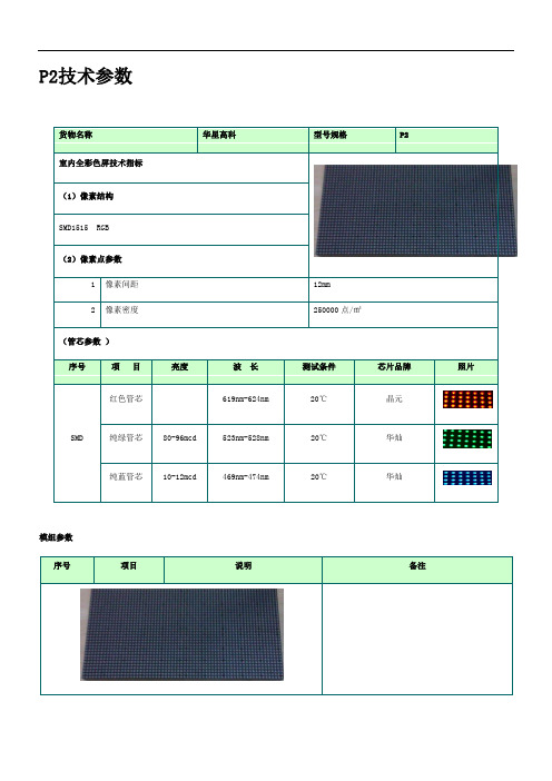
货物名称
华星高科
型号规格
P2
室内全彩色屏技术指标
(1)像素结构
SMD1515 RGB
(2)像素点参数
1
像素间距
12mm
2
像素密度
250000点/㎡
(管芯参数)
序号
项 目
亮度
波 长
测试条件
芯片品牌
照片
SMD
红色管芯
619nm-624nm
20℃
晶元
纯绿管芯
80-96mcd
523nm-528nm
22
箱体防护等级
IP43
23
屏体材质
压铸铝512*512
24
软件系统
终身免费升级
25
保护技术
防潮、防尘、防腐、防静电、防雷击,同时具有过流、短路、过压、欠压保护
精心搜集整理,只为你的需要
精心搜集整理,只为你的需要
13
使用寿命
100,000小时
14
连续工作时间
≧72小时
15
软件工作环境
Windows
16
系统环境温度
—20℃~60℃
17
系统环境湿度
10%—90%RH
18
最大功耗
700W/m2
19
平均功耗
350W/m2
20
供电要求
AC220V
21
视频信号
AV、S-Video、VGA 、DVI、HDMI、SDI、DP
20℃
华灿
纯蓝管芯
10-12mcd
469nm-474nm
20℃
华灿
模组参数
序号
项目
说明
备注
超级离心机技术方案

超级离心机技术规格书设备名称: 超级焦油三相离心机(阿法拉伐) P2-3252009年11月2日一. 超级离心机技术规格:1.用途:脱除焦油中的水和焦油渣。
2.操作环境极端最高温度38.9℃极端最低温度-28。
2℃年平均最高温度℃年平均最低温度℃当地大气压:夏季平均气压:1002.2hPa冬季平均气压: 1023.4hPa环境湿度:最冷月平均相对湿度:52%最热月平均相对湿度:79%年平均降雨量:678.3m海拔高度:90.00m抗震设防烈度:7度安装位置室外3.技术要求3.1设备处理能力介质:焦油处理量:8~9t/h焦油中>100μ渣:入口≤10%出口≤0。
1%焦油中水: 入口≤10%出口≤2%3。
2 介质温度<100℃介质压力0.2~0。
3MPa(表)4.设备结构:卧式螺旋卸料5.使用寿命:螺旋体与转筒输送介质的耐磨层使用寿命5年,轴承、密封件一年。
5.设备材料:由甲方指定6.电源:380V 50HZ7.供货范围:2台每台主要包括本体1台、转筒驱动电机1台、螺旋驱动电机1台、主控制柜1套、现场控制柜1套、机器连接软管1套、进料流量计及调节阀1套、维修专用工具及备品备件等.驱动电机外形尺寸按 IEC60072-1规定。
卖方提供设备安装图及相关技术文件.二. 超级焦油三相分离离心机工艺保证值及规格:2。
1. 工艺保证值:2。
1.1. 设备型号P2—3252。
1.2单机进料8~9t/h,其中最高含固率≤10.0%。
2。
1.3 分离后焦油中含固率≤0.1%(颗粒大于100µ)2。
1。
4 分离后焦油中含水率≤2%2。
2. 卧式离心分离机规格:机型: P2—325,为逆流卧式螺旋卸料沉降离心机,由圆锥圆柱型转筒和内螺旋构成,在离心力作用下可对物料进行每天24小时连续的三相分离。
结构:柱锥形卧螺离心机,圆锥圆柱型转筒、内螺旋、罩壳、电机、行星减速机、变频器及控制系统、机座、轴承座组合、隔震垫、地脚螺栓等组成。
PET聚酯薄膜(玛拉)绝缘胶带规格书TDS 模板

文件編號 No. 名 稱 Name聚酯薄膜(瑪拉)膠帶P2xx (xx=06、07、08、09、10、11、12) 規格書Specification of Polyester Adhesive Tape P2xx(xx=06、07、08、09、10、11、12)頁 數 Page2/3規 格SPEC 依訂單要求Any length as order 項 目Item 單 位Unit 規格值Standard Value 試驗標準Inspect Basis寬 度Width mm 依訂單要求±0.2 Requested Spec±0.2 ASTM D-1000 長 度LengthM依訂單要求±2% Requested Spec±2%ASTM D-10003、品質特性Quality characteristics :項 目Item 單 位Unit 規格值Standard Value試驗標準Inspect Basis總 厚 度Total Thicknessmm 0.050±0.005 ASTM D-1000 黏著力Adhesion StrengthKg/25mm 0.70±0.20 ASTM D-1000 張力強度Tensile StrengthKgf/25mm9.0↑ ASTM D-1000 伸長率Elongation% 80 ASTM D-1000耐溫性Temp, Resist ℃ 130 SIP-08 耐溶性Solvent Resistance.- 優ExcellentSIP-08 耐電壓性Voltage ResistanceKV5.0SIP-08本表所列之數字僅代表參考性質,不作為驗收標準;其功能性是否適合?請使用者自行驗證 The above information is for reference only and should not be employed as inspection standard ;To avoid the wrong with usage, please carefully tested by user before any uses.原制定日期 Original Date第B 版 B Edition亞克力膠Acrylic Adhesive。
室内P2.0技术规格书
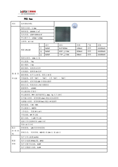
连续工作无故障时间:1000小时
寿命:10万小时
配合
控制系统
控制系统:LED同步控制系统
控制方式:同步控制, HUB板:高256点,宽128点
配套
屏体
每平方单元板数61PCS
每平方电源(5V60A)数:5PCS
每平方数平均功耗:325W
每平方数最大功耗:810W
520mcd
深圳
1515black
蓝
SANAN
470+/_2.5nm
85mcd
深圳
1515black
物理分辨率:4096点/块
单元重量:70g
最小视距:≥2m
最佳视距:高度的3倍率
有效视距:面积的30倍率
最佳视角:水平±140度,垂直±45度
环境温度:存贮-35℃~+85℃工作-20℃~+50℃
驱动器件:采用节能LED专用驱动器件
驱动方式:恒流动态1/32扫描驱动
刷新频率:1200HZ
单元板结构:灯驱合一
单元板材质:FR-4玻纤板厚度1.6mm,Tg大于170℃
信号输入材质:采用纯铜10mil镀金反扣试排母
电源输入材质:采用纯铜8mil镀金4P接插件
相对湿度:≤90~95%
单元板接口:HUB75
工作电压:直流5V±10%
平均功耗:6W/单元板
PH2.0mm
项目
技术指标参数:
像素管单元板
物理点间距:2.0mm
物理密度:250000点/m2
发光亮度:1200-1500cd/m2
单元板尺寸:128mm×128mm
分辨率:64×64
像素1R1G1B
晶片
车规级片式电阻器技术规格书

Automotive Grade Chip Resistor 【CR..A Series 】Automotive Grade Chip Resistor-CR..A Series■Scope-This specification applies to all sizes of rectangular-type fixed chip resistors with Ruthenium-base as material.■Features-AEC-Q200 Compliance-Highly reliable multilayer electrode construction -Compatible with all soldering process■Construction■Applications-Automotive Industry-Telecommunication Equipments -Radio and Tape Recorders, TV Tuners -Digital Cameras, Watches, Pocket Calculators-Computers, Instruments■Part NumberingPart Number :CR-03FA7---10R■Recommend Land Pattern■Soldering ConditionIR Reflow Soldering Wave Soldering (Flow Soldering)(1)Time of IR reflow soldering at maximum temperature point 260︒C :10s (2)Time of wave soldering at maximum temperature point 260︒C :10s (3)Time of soldering iron at maximum temperature point 410︒C :5s■Standard Electrical SpecificationsOverload Voltage=2.5*√(P*R) or Max. Overload Voltage listed above, whichever is lower. ■Viking is capable of manufacturing the optional spec based o n customer’s requirement.RCWV(Rated Continuous Working Voltage)=√(P*R) or Max. Operating Voltage whichever is lower.■Storage Temperature: 15~28°C; Humidity < 80%RH▓PackagingReel Specifications & Packaging QuantityPaper Tape SpecificationsTop TapeBottom TapeEmbossed Plastic Tape Specifications■MarkingNo Marking for 0201/0402 Jumper for all: Letter “0”1% for 0805/1206/1210/2010/2512: 4 digits markingExample:5% for 0603/0805/1206/1210/2010/2512: 3 digits marking in E24Example: 101=100Ω 102=1K Ω (1st and 2nd are E24 code and 3rd code is multiplier)1% for 0603(E24): 3 digits marking in E24, When the E24 and E96 are the same resistance, this marking in E96Example: 01A= 100Ω 05C=11K Ω 123=12K Ω 273=27K Ω1% for 0603(E96): 3 digits marking in E963 digits marking for Example: 14C=13K7Ω13C=13K3Ω 68B=4K99Ω68X=49.9Ω14CψD 11.5+0.25,-0Top Tape。
P11P22P91工艺焊接技术交底记录

c预热宽度:从坡口中心每侧不少于3倍的管壁厚。
●氩弧焊打底
a氩弧焊打底在管道预热到规定温度并加热均匀后进行;打底采用直流正接法、两人对称焊接。
bSA335P91材质大径管道:打底焊采用内填丝法。
c氩弧焊打底时采用高频引弧、衰减收弧;氩弧焊电流80~110A;氩弧焊打底时,焊接速度不宜太快,焊层厚度不少于3mm。
R307
ER80S-B2
TWE-811B2
A691 GR.1-1/4CR
R307
ER80S-B2
TWE-811B2
A335 GR.P22
R407
ER90S-B3
TWE-911B3
A335 GR.P91
E9015-B9
ER90S-B9
不采用
表C7.9-1编号:
附页:
●氩弧焊打底
a氩弧焊打底在管道预热到规定温度并加热均匀后进行;打底采用直流正接法。
c根层焊接、层间清理及焊接检查
根层焊接:需注意管道内部氩气充满且稳定后方可进行根层焊接,以防止根层氧化;注意打底质量,两人对称焊时要相互帮助检查。层间清理和检查:注意层间清理检查,上层检查合格后及时进行次层焊接;焊接时注意两侧坡口及根部要熔合良好,避免未熔合缺陷的产生;注意接头收弧质量,在熔池边缘处收弧,收弧时注意填加铁水并要保证弧坑饱满,以避免弧坑裂纹的产生;要注意接头的打磨。热处理后,应对P91钢焊接接头收弧处进行检查;由于采用了电流的衰减性能以及注意接头的打磨,故本工程有效避免了表面弧坑裂纹现象。
c中间层采用φ4.0mm焊条,电流110-150A;各层接头应互相错开,焊工要加强层间清理,严防焊缝夹渣。
FPGA可编程逻辑器件芯片XC2VP2-6FG456I中文规格书
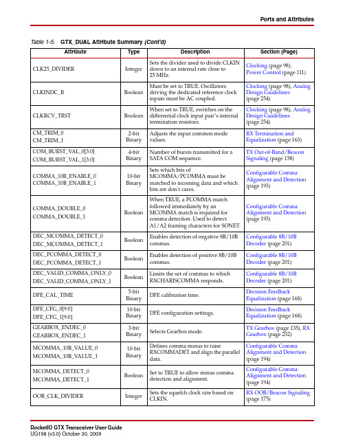
DEC_PCOMMA_DETECT_0 DEC_PCOMMA_DETECT_1
Boolean
Enables detection of positive 8B/10B commas.
Configurable 8B/10B Decoder (page 201)
DEC_VALID_COMMA_ONLY_0 DEC_VALID_COMMA_ONLY_1
Set to FALSE (default) to disable. Set to TRUE to enable.
PLL_LKDET_CFG
3-bit Configuration for the shared PMA PLL Binary lock detect circuit.
PLL_RXDIVSEL_OUT_0 PLL_RXDIVSEL_OUT_1
Shared PMA PLL (page 87)
PLL_DIVSEL_REF
Integer
Controls the reference clock divider of the shared PMA PLL.
Shared PMA PLL (page 87)
PLL_FB_DCCEN
Boolean
PLL DCC enable.
Configurable Comma Alignment and Detection (page 193)
DEC_MCOMMA_DETECT_0 DEC_MCOMMA_DETECT_1
Boolean
Enables detection of negative 8B/10B commas.
Configurable 8B/10B Decoder (page 201)
MSS2P3-M389A;MSS2P2-M389A;中文规格书,Datasheet资料
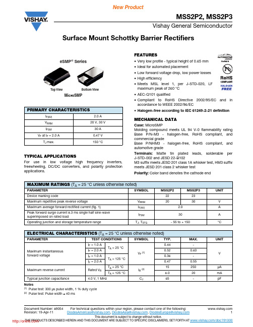
Document Number: 89054For technical questions within your region, please contact one of the following: Revision: 19-Apr-11DiodesAmericas@ , DiodesAsia@ , DiodesEurope@ 1This document is subject to change without notice.THE PRODUCTS DESCRIBED HEREIN AND THIS DOCUMENT ARE SUBJECT TO SPECIFIC DISCLAIMERS, SET FORTH AT /doc?91000Surface Mount Schottky Barrier RectifiersMSS2P2, MSS2P3Vishay General SemiconductorTYPICAL APPLICATIONSFor use in low voltage high frequency inverters,freewheeling, DC/DC converters, and polarity protection applications.FEATURES•Very low profile - typical height of 0.65 mm •Ideal for automated placement•Low forward voltage drop, low power losses •High efficiency•Meets MSL level 1, per J-STD-020, LF maximum peak of 260 °C •AEC-Q101 qualified•Compliant to RoH S Directive 2002/95/EC and in accordance to WEEE 2002/96/EC•Halogen-free according to IEC 61249-2-21 definitionMECHANICAL DATACase: MicroSMPMolding compound meets UL 94 V-0 flammability rating Base P/N-M3 - halogen-free, RoH S compliant, and commercial gradeBase P/NH M3 - halogen-free, RoH S compliant, and automotive gradeTerminals: Matte tin plated leads, solderable per J-STD-002 and JESD 22-B102M3 suffix meets JESD 201 class 1A whisker test, HM3 suffix meets JESD 201 class 2 whisker testPolarity: Color band denotes the cathode endNotes(1)Pulse test: 300 μs pulse width, 1 % duty cycle (2)Pulse test: Pulse width 40 msPRIMARY CHARACTERISTICSI F(AV) 2.0 A V RRM 20 V, 30 V I FSM30 AV F at IF = 2.0 A0.47 V T J max.150 °CMicroSMPeSMP® SeriesTop View Bottom ViewMAXIMUM RATINGS (T A = 25 °C unless otherwise noted)PARAMETER SYMBOLMSS2P2MSS2P3UNITDevice marking code2223Maximum repetitive peak reverse voltage V RRM 2030V Maximum average forward rectified current (fig. 1)I F(AV) 2.0A Peak forward surge current 8.3 ms single half sine-wave superimposed on rated loadI FSM 30A Operating junction and storage temperature rangeT J , T STG - 55 to + 150°C ELECTRICAL CHARACTERISTICS (T A = 25 °C unless otherwise noted)PARAMETERTEST CONDITIONS SYMBOLTYP.MAX.UNITMaximum instantaneous forward voltageI F = 1.0 AT A = 25 °CV F (1)0.44-V I F = 2.0 A 0.520.60I F = 1.0 A T A = 125 °C 0.36-I F = 2.0 A0.470.55Maximum reverse current Rated V R T A = 25 °C I R (2)15250μA T A = 125 °C6.020mA Typical junction capacitance4.0 V, 1 MHzC J 65-pF / For technical questions within your region, please contact one of the following:Document Number: 890542DiodesAmericas@ , DiodesAsia@ , DiodesEurope@ Revision: 19-Apr-11This document is subject to change without notice.THE PRODUCTS DESCRIBED HEREIN AND THIS DOCUMENT ARE SUBJECT TO SPECIFIC DISCLAIMERS, SET FORTH AT /doc?91000MSS2P2, MSS2P3Vishay General SemiconductorNote(1)Thermal resistance from junction to ambient and junction to lead mounted on PCB with 6.0 mm x 6.0 mm copper pad areas R θJL is measured at the terminal of cathode band. R θJC is measured at the top center of the bodyNote(1)Automotive gradeRATINGS AND CHARACTERISTICS CURVES(T A = 25 °C unless otherwise noted)Fig. 1 - Maximum Forward Current Derating Curve Fig. 2 - Forward Power Loss CharacteristicsFig. 3 - Typical Instantaneous Forward CharacteristicsFig. 4 - Typical Reverse CharacteristicsTHERMAL CHARACTERISTICS (T A = 25 °C unless otherwise noted)PARAMETER S YMBOL M S S 2P2M S S 2P3UNITTypical thermal resistanceR θJA (1)105°C/WR θJL (1)15R θJC (1)20ORDERING INFORMATION (Example)PREFERRED P/N UNIT WEIGHT (g)PREFERRED PACKAGE CODEBASE QUANTITYDELIVERY MODEMSS2P3-M3/89A 0.00689A 45007" diameter plastic tape and reel MSS2P3HM3/89A (1)0.00689A45007" diameter plastic tape and reel/Document Number: 89054For technical questions within your region, please contact one of the following: Revision: 19-Apr-11DiodesAmericas@ , DiodesAsia@ , DiodesEurope@ 3This document is subject to change without notice.THE PRODUCTS DESCRIBED HEREIN AND THIS DOCUMENT ARE SUBJECT TO SPECIFIC DISCLAIMERS, SET FORTH AT /doc?91000MSS2P2, MSS2P3Vishay General SemiconductorFig. 5 - Typical Junction Capacitance Fig. 6 - Typical Transient Thermal ImpedancePACKAGE OUTLINE DIMENSIONSin inches (millimeters)/Legal Disclaimer Notice VishayDisclaimerALL PRODU CT, PRODU CT SPECIFICATIONS AND DATA ARE SU BJECT TO CHANGE WITHOU T NOTICE TO IMPROVE RELIABILITY, FUNCTION OR DESIGN OR OTHERWISE.Vishay Intertechnology, Inc., its affiliates, agents, and employees, and all persons acting on its or their behalf (collectively,“Vishay”), disclaim any and all liability for any errors, inaccuracies or incompleteness contained in any datasheet or in any other disclosure relating to any product.Vishay makes no warranty, representation or guarantee regarding the suitability of the products for any particular purpose or the continuing production of any product. To the maximum extent permitted by applicable law, Vishay disclaims (i) any and all liability arising out of the application or use of any product, (ii) any and all liability, including without limitation special, consequential or incidental damages, and (iii) any and all implied warranties, including warranties of fitness for particular purpose, non-infringement and merchantability.Statements regarding the suitability of products for certain types of applications are based on Vishay’s knowledge of typical requirements that are often placed on Vishay products in generic applications. Such statements are not binding statements about the suitability of products for a particular application. It is the customer’s responsibility to validate that a particular product with the properties described in the product specification is suitable for use in a particular application. Parameters provided in datasheets and/or specifications may vary in different applications and performance may vary over time. All operating parameters, including typical parameters, must be validated for each customer application by the customer’s technical experts. Product specifications do not expand or otherwise modify Vishay’s terms and conditions of purchase, including but not limited to the warranty expressed therein.Except as expressly indicated in writing, Vishay products are not designed for use in medical, life-saving, or life-sustaining applications or for any other application in which the failure of the Vishay product could result in personal injury or death.Customers using or selling Vishay products not expressly indicated for use in such applications do so at their own risk and agree to fully indemnify and hold Vishay and its distributors harmless from and against any and all claims, liabilities, expenses and damages arising or resulting in connection with such use or sale, including attorneys fees, even if such claim alleges that Vishay or its distributor was negligent regarding the design or manufacture of the part. Please contact authorized Vishay personnel to obtain written terms and conditions regarding products designed for such applications.No license, express or implied, by estoppel or otherwise, to any intellectual property rights is granted by this document or by any conduct of Vishay. Product names and markings noted herein may be trademarks of their respective owners.Material Category PolicyVishay Intertechnology, Inc. hereb y certifies that all its products that are identified as RoHS-Compliant fulfill the definitions and restrictions defined under Directive 2011/65/EU of The European Parliament and of the Council of June 8, 2011 on the restriction of the use of certain hazardous substances in electrical and electronic equipment (EEE) - recast, unless otherwise specified as non-compliant.Please note that some Vishay documentation may still make reference to RoHS Directive 2002/95/EC. We confirm that all the products identified as being compliant to Directive 2002/95/EC conform to Directive 2011/65/EU.Revision: 12-Mar-121Document Number: 91000 /分销商库存信息:VISHAY-GENERAL-SEMICONDUCTOR MSS2P3-M3/89A MSS2P2-M3/89A。
非晶硅薄膜太阳能电池产品技术规格书

非晶硅薄膜太阳能电池组件技术规格书编制:审核:批准:发布日期:实施日期:电池组件的正面、侧面和背面如图2-1所示:C E 1^.04 MOO图2-1电池的正面、侧面和背面示意图1.2 产品组成产品由TCO 导电玻璃、P-I-N 非晶硅薄膜、AZO 薄膜、Al 薄膜、NiV 薄膜、 引流脩、汇流条、绝缘膜、PVB 、背板玻璃、接线盒和导线等组成。
1.3 名词解释1.3.1 引流条:即Side Bus ,材料为铝带,采用超声波焊接在背电极膜层上, 其作用是将组件的正负极电流顺利引出。
1.3.2 汇流条:即Cross Bus ,材料为铜锡复合带,采用绝缘胶将其粘附在背 电极膜层上,其作用是将引流条上的电流汇到接线盒。
1.3.3 接线盒:即Junction Box ,其作用是引出组件的正负极,同时起到防潮、 防尘和密封功能。
1 1. 1.1. 22.2.适用范围 本技术标准适用于非晶硅单节薄膜太阳电池组件系列产品 型号:-80,-85,-90,-95,-100,-105。
结构:a-Si 单节 Thin Film PV Module产品结构1产品外形1.1 1.2 1.3 长度 宽度 厚度 1300mm ± 1 mm 1100mm ±1 mm 3. 9mm ± 0.8 mm 正面 侧面背面7.9±2-.^.5优。
麻渊1 痴阳画出51抬时包邮遇?.口。
—桐脚川3 5 I'、.. 蓑=尹+学吟19 R3产品规格3.1产品型号3.1.1-80,-85,-90,-95,-100,-105 系列3.1.2分类等级:80W、85W、90W、95W、100W和105W六个等级。
情况如下:80W: 77.5〜82.5W 85W: 82.6〜87.5W90W: 87.6〜92.5W 95W: 92.6〜97.5W100W: 97.6〜102.5W 105W: 102.6〜107.5W3.2产品属性表 3-1产品属性3.3电性规格:3.4温度系数规格表3.5产品工作范围3-44电池构造4.1子电池构造4.1.1子电池宽度:8.04mm (正极宽度:6.5mm;负极宽度:8.22mm) 4.1.2子电池数量:133个4.1.3清边宽度:12mm4.1.4汇流条宽度:4mm4.2引流条与汇流条的相对位置4.2.1背板玻璃孔洞中心位置距玻璃短边为175mm,距玻璃长边为550mm。
P2室内全彩LED软模组规格书
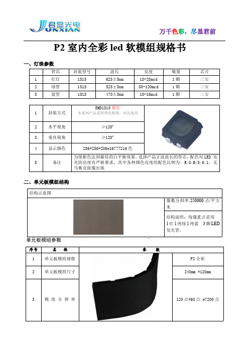
P2 室内全彩 led 软模组规格书
一、灯珠参数
管芯
1
红灯
2
绿管
3
蓝管
封装型号 1515 1515 1515
波长 625±5nm 525±5nm 470±5nm
亮度 18-28mcd 80-120mcd 10-16mcd
数量 1颗 1颗 1颗
芯片 三安 三安 三安
SMD1515 黑灯
第 2页 共 4页
[键入文字]
23
播放方式
视频、动画、文字信息等交替使用或任意组合
24
信号处理能力
不低于 12bit(超越自然界色彩数,画质更出色)
25
计算机显示模式
1024×768;1280×768;800×600
26
图像切换
VGA 同步同帧
27
反γ校正曲线
具备三条以上可调节的γ曲线
28
控制系统采用
二、单元板模组结构
结构示意图
单元板模组参数
序号
名称
1 单元板模组规格
像数分辩率:250000 点/平方 米
结构说明:每像素点采用 1 红 1 纯绿 1 纯蓝 3 颗 LED 发光管。
参数
P2 全彩
2 单元板模组尺寸
240mm *120mm
3 模组分辨率
120 点*60 点 =7200 点
三.模组参数
灰度/颜色/对比 18
度
逻辑 65536 灰度,颜色:10.7 亿色
术 19
图像调节
白平衡/对比度/视觉修正/色度调节/单模组调亮度
20
参
亮度调节方式 软件 100 级可调,根据不同环境亮度自动或手动调节显示亮度
力兴 cr-p2 锂锰柱式电池 技术规格书说明书

武 汉 力 兴( 火 炬 ) 电 源 有 限 公 司1.目的1.1对武汉力兴(火炬)电源有限公司出品的锂电池的产品规格、测试方法进行规范,避免因测试条件、方法的不同引起偏差。
1.2指导客户正确选择和使用我公司电池。
2. 产品类别和产品型号表1类别型号锂锰柱式电池CR-P23.产品基本特性表2序号项目特性1 标称容量* 1500 mAh2 放电容量(10mA放电终止电压4.0V)1400±100 mAh3 标称电压6V4 工作温度范围 -40~+85℃5 最大脉冲电流3500 mA6 最大连续放电电流1500mA7 结构及成分二氧化锰正极、锂负极、有机电液、隔膜及钢外壳等8 重量参考值38 g* 标称容量:数值是在10mA、20±2℃,截止电压为4.0V的条件下测得的。
(所测得的容量值会随着放电电流、温度以及截止电压的不同而变化)4.外形示意图及尺寸4.1外形示意图如下a)外形尺寸表3电池型号 长度L( mm ) 宽度W ( mm ) 高度H( mm )CR-P2 32.5-35.0 18.5-19.8 34.5-36.05.外观外观整洁,标志清晰,无漏液,正负极标识正确,壳底和防爆盖表面无变形、锈迹、污点。
6.性能及测试方法6.1电性能表4序号项目测试条件常温一年内性能常温存储一年后性能1 开路电压室温低温高温20±2℃-20±2℃60±2℃≥6.0V≥6.0V≥6.0V≥6.0V≥6.0V≥6.0V2 工作电压室温低温高温放电负载:20Ω20±2℃-20±2℃60±2℃≥5.4V≥5.1V≥5.5V≥5.3V≥5.0V≥5.4V3 工作寿命室温低温高温放电电流:10mA终止电压:4.0V20±2℃-20±2℃60±2℃≥1300mAh≥950mAh≥1250 mAh≥1250 mAh≥900mAh≥1200 mAh4室温容量快速检测放电电流:50mA终止电压:4.0V≥1150 mAh ≥1100 mAh6.2性能检验6.2.1每项试验的样品数为6组。
VDA6.3-2016 P2-P7要素部分
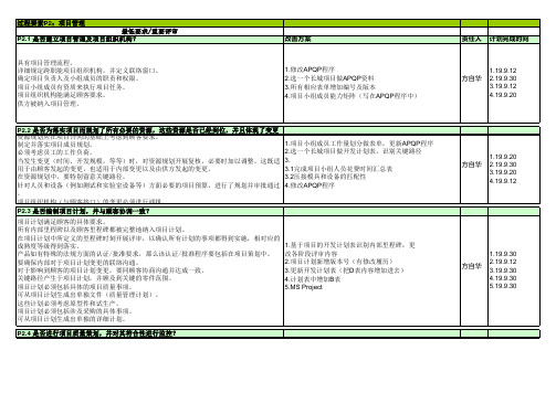
P2.2 是否为落实项目而规划了所有必要的资源,这些资源是否已经到位,并且体现了变更情况?
资源规划应在项目合同的基础上考虑到顾客要求。 制定并落实项目成员规划。
1.项目小组成员工作量划分做表单,更新APQP程序
必须考虑员工的工作负荷。
2.选一个长城项目做开发计划表,识别关键路径
当发生变更(时间、开发规模,等等)时,对资源规划开展复核,必要时加以调整。这既适 3.
过程要素P3:产品和过程开发的策划 最低要求/重要评审
P3.1 针对产品和过程的具体要求是否已明确?
方自华 1、2. 19.9.12 3. 19.9.30
1.19.9.30 方自华 2.19.9.30
3.19.9.20
方自华 1.19.9.12 2.19.9.12 3.19.9.12
方自华 19.9.12
确保顾客要求在供应链上的传递。也包括在协议中规定的顾客指定的供方(指定供方)的事 纳入项目计划表
项。设施、设备、工装、试验、测量系统以及服务的供方都被纳入。必须对供方定点活动加 2.如有涉及供应商开发的里程碑纳入计划表中
以适当的清晰的记录。定点日期、供方里程碑以及批准事项已经体现在计划里并与总体时间 3.拟定一份供应商开发协议
P7.4 针对投诉是否开展了失效分析,并且有效地落实了纠正措施?*
过程要素P4:产品和过程开发的实现 过程要素P5:供应商管理 最低要求/重要评审
P5.1是否只和获得批准/放行且具备质量能力的供方开展合作?
在量产过程中,必须确保只和批准/放行的供方开展合作。 按规定的标准对供方质量能力开展评价。 对现有供方的质量绩效进行评估。 识别并评价供应链中的风险,通过适当措施加以降低(应急策略)。
P5.2 在供应链中是否考虑到顾客要求? 对顾客要求的传递必须加以规范,并且保证可追溯。 顾客要求包括来自质量协议和有效规范里的技术图纸、零部件、软件方面的要求。 还必须考虑到量产中的变更管理。 对应的接口已经确定并且加以了保证。
新CW13J-017中文版产品规格书_P2_

● 电芯的智能平衡处理,平衡电流可通过 外部器件灵活调整
● 充放电过程中有相应的温度保护 ● 硬件的过流、短路保护功能处理 ● 所有的保护延时均可编程设置 ● 标准的 I2C 接口 ● 精确报告电池当前电量信息 ● 精确的实时时钟功能 ● 在充电开始、停止充电、放电完全结束时,
记录电池实际容量(FCC)、剩余电量(RM)、 电压、电流以及时间点,而且即使保护板已 损坏也可以读取这些数据。
力通威电子有限公司
LI TONG WEI ELECTRONIC TECHNOLOGY CO.,LTD
TEL: 0755-81489983 FAX: 0755-81489955 Add: 深圳市宝安区龙华镇大浪同胜村上横朗
百富利工业园 C 栋 http:
样品规格书
客户名称 绿威长宜 送样日期 2012.04.28 版次 V1.0 页数 15
LT-GP705 SPEC
文件编号: LTW-QR-YF1979
LT-GP705(7S)SPEC
1. 介绍 Introduction
LT-GP705 是力通威公司专门针对锂电动自行车 5~7 串电池包而设计的保护板方案;可适用不同化学 性质的锂电芯,如锂离子、锂聚合物、磷酸铁锂等。
保护板预留了两个 I2C 通讯接口,保护部份通讯 端口可用来设置各种保护电压、电流等参数,灵活性 很强。保护板带载能力强,持续放电电流最大可达 16A。
400
uA
120
150
uA
以上参数为推荐值,用户可以依据实际应用进行修改
REV 1.0 4/20/2012
Characteristics subject to change without notice. 2 of 14
海尔 P-J-F-2-120 1.90 0.80-P2(J) 120升平板太阳能热水器 使用说明书

二、 产品介绍
额定内压 额定电源 能效等级 能效系数(CTP)
0.80MPa 50Hz 220V~
1级 0.45
以上参数采光面积偏差≤3%,容积偏差在±3%以内,储水箱外形尺寸允许误 差范围为±10%。
该系列太阳热水器执行国家标准:GB 4706.12,GB/T19141-2011,GB 26969-2011。
-3-
三、 使用说明
三、 使用说明
3.1. 注意事项 3.1.1. 电气方面
电源 警示:
• 务必使用 220V/50Hz 的独立电源。
• 发现热水器有异常或闻到焦臭味的情况下,请立即切断电源, 并与服务中心联系。
• 必须做好避雷措施,当出现雷电时必须关闭电源。 • 长期不使用时请断开电源。
• 如果电源线损坏必须由售后或专门技术维修人员用符合国家规 定的线缆进行更换。
支架包装箱
1套
注:本产品因不断研究改进,保留热水器各部件的变更权利,恕不另行通 知,敬请谅解。
3.2.2. 安装注意事项
安装注意事项
1. 为方便热水器水箱的安装拆卸,建议在热水器进出水管适当位置分别加 G1/2 活接。
2. 应确保自来水进水压力不小于 0.05MPa,最大压力不超过 0.8MPa。系统安 全阀的泄压孔应接到污水排污处。
2.3. 技术数据.......................................... 3 2.3.1. 技术数据.......................................... 3
三、 使用说明................................ 品牌介绍视频
2.2. 产品部件 2.2.1. 电气原理图 电气原理图
NSR0240P2T5G;中文规格书,Datasheet资料
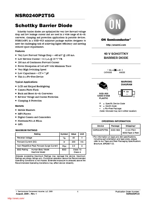
© Semiconductor Components Industries, LLC, 2009 August, 2009 − Rev. 11Publication Order Number:NSR0240P2/DNSR0240P2T5GSchottky Barrier DiodeSchottky barrier diodes are optimized for very low forward voltage drop and low leakage current and are used in a wide range of dc−dc converter, clamping and protection applications in portable devices. NSR0240P2 in a SOD−923 miniature package enables designers to meet the challenging task of achieving higher efficiency and meeting reduced space requirements.Features•Very Low Forward V oltage Drop − 460 mV @ 100 mA •Low Reverse Current − 0.2 m A @ 25 V VR•200 mA of Continuous Forward Current•Power Dissipation of 240 mW with Minimum Trace•Very High Switching Speed•Low Capacitance − CT = 7 pF•This is a Pb−Free DeviceTypical Applications•LCD and Keypad Backlighting•Camera Photo Flash•Buck and Boost dc−dc Converters•Reverse V oltage and Current Protection•Clamping & ProtectionMarkets•Mobile Handsets•MP3 Players•Digital Camera and Camcorders•Notebook PCs & PDAs•GPSMAXIMUM RATINGSRating Symbol Value Unit Reverse Voltage V R40VForward Current (DC)I F200mA Non−Repetitive Peak Forward Surge Current I FSM 2.0AESD Rating:Human Body ModelMachine Model ESD Class 1CClass AStresses exceeding Maximum Ratings may damage the device. Maximum Ratings are stress ratings only. Functional operation above the RecommendedOperating Conditions is not implied. Extended exposure to stresses above the Recommended Operating Conditions may affect device reliability.40 V SCHOTTKYBARRIER DIODE12Device Package Shipping†ORDERING INFORMATIONNSR0240P2T5G SOD−923 2 mm Pitch8000/Tape & Reel †For information on tape and reel specifications, including part orientation and tape sizes, please refer to our Tape and Reel Packaging Specifications Brochure, BRD8011/D.SOD−923CASE 514ABPLASTICP= Specific Device CodeM=Month CodeG= Pb−Free Package(Note: Microdot may be in either location)MARKINGDIAGRAM2THERMAL CHARACTERISTICSCharacteristicSymbol MinTypMax Unit Thermal ResistanceJunction −to −Ambient (Note 1)Total Power Dissipation @ T A = 25°C R q JA P D 520240°C/W mW Thermal ResistanceJunction −to −Ambient (Note 2)Total Power Dissipation @ T A = 25°C R q JA P D 175710°C/W mW Junction and Storage Temperature RangeT J , T stg−55 to +150°C1.Mounted onto a 4 in square FR −4 board 10 mm sq. 1 oz. Cu 0.06” thick single sided. Operating to steady state.2.Mounted onto a 4 in square FR −4 board 1 in sq. 1 oz. Cu 0.06” thick single sided. Operating to steady state.ELECTRICAL CHARACTERISTICS (T A = 25°C unless otherwise noted)CharacteristicSymbol MinTyp Max Unit Reverse Leakage (V R = 25 V)(V R = 40 V)I R0.20.80.555.0m AForward Voltage (I F = 10 mA)(I F = 100 mA)(I F = 200 mA)V F0.340.460.540.3650.500.60VTotal Capacitance(V R = 1.0 V, f = 1 MHz)CT7.0pFFigure 1. Forward VoltageFigure 2. Leakage CurrentV F , FORWARD VOLTAGE (V)V R , REVERSE VOLTAGE (V)0.000010.00010.0010.010.1101001000Figure 3. Total CapacitanceV R , REVERSE VOLTAGE (V)I F , F O R W A R D C U R R E N T (m A )I r , R E V E R S E C U R R E N T (m A )C T , T O T A L C A P A C I T A N C E (p F )1PACKAGE DIMENSIONSSOD −923CASE 514AB −01ISSUE BNOTES:1.DIMENSIONING AND TOLERANCING PER ANSI Y14.5M, 1982.2.CONTROLLING DIMENSION: MILLIMETERS.3.MAXIMUM LEAD THICKNESS INCLUDES LEAD FINISH THICKNESS. MINIMUM LEADTHICKNESS IS THE MINIMUM THICKNESS OF BASE MATERIAL.DIM MIN NOM MAX MILLIMETERS A 0.340.370.40b 0.150.200.25c 0.070.120.17D 0.750.800.85E 0.550.600.650.95 1.00 1.05L0.050.100.15H E 0.0130.0150.0160.0060.0080.0100.0030.0050.0070.0300.0310.0330.0220.0240.0260.0370.0390.0410.0020.0040.006MINNOM MAX INCHES cA2X0.08 (0.0032)X Y0.400.90DIMENSIONS: MILLIMETERS*For additional information on our Pb −Free strategy and soldering details, please download the ON Semiconductor Soldering and Mounting Techniques Reference Manual, SOLDERRM/D.SOLDERING FOOTPRINT*ON Semiconductor and are registered trademarks of Semiconductor Components Industries, LLC (SCILLC). SCILLC reserves the right to make changes without further notice to any products herein. SCILLC makes no warranty, representation or guarantee regarding the suitability of its products for any particular purpose, nor does SCILLC assume any liability arising out of the application or use of any product or circuit, and specifically disclaims any and all liability, including without limitation special, consequential or incidental damages.“Typical” parameters which may be provided in SCILLC data sheets and/or specifications can and do vary in different applications and actual performance may vary over time. All operating parameters, including “Typicals” must be validated for each customer application by customer’s technical experts. SCILLC does not convey any license under its patent rights nor the rights of others. SCILLC products are not designed, intended, or authorized for use as components in systems intended for surgical implant into the body, or other applications intended to support or sustain life, or for any other application in which the failure of the SCILLC product could create a situation where personal injury or death may occur. Should Buyer purchase or use SCILLC products for any such unintended or unauthorized application, Buyer shall indemnify and hold SCILLC and its officers, employees, subsidiaries, affiliates,and distributors harmless against all claims, costs, damages, and expenses, and reasonable attorney fees arising out of, directly or indirectly, any claim of personal injury or death associated with such unintended or unauthorized use, even if such claim alleges that SCILLC was negligent regarding the design or manufacture of the part. SCILLC is an Equal Opportunity/Affirmative Action Employer. This literature is subject to all applicable copyright laws and is not for resale in any manner.PUBLICATION ORDERING INFORMATION分销商库存信息: ONSEMINSR0240P2T5G。
松下 P2 系列 DVDPRO 说明书
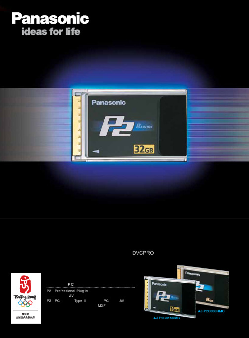
AJ-P2C008HMC AJ-P2C016RMC
※ 此版本为简略介绍,如需更详细资料,请从经销商处获取。
3万次插入/拔出 高可靠性接口
写保护开关
备忘区
铝压铸外壳
存储卡序列号
条形码
大容量、高速度的超轻薄卡
现在,P2家族又添新成员。新推出的AJ-P2C032RMC是一种容量为 32GB的卡,这将DVCPRO或DV的录制时间延长至128分钟。而且 这种32GB P2卡还支持32分钟的DVCPRO HD录制。数据传输速度 高达640Mbps,这大幅度地加快了制作流程。
ING
!"#$
1 = IT
P2
P2 !"
(P2 CAM)
!"##$ENG
ING
!
P =
P2
mO
!
!"#$%
!"#$%&'()*+ ! !
P2 CAM
!"#$%& !"#$% (NTSC)/600,000 !" !"#$%&'()*+,-./012 !"#$% 2/3 !" 2000LUX !"#$%& 0.001LUX !"#$ LCD !"#$ !"# P2 !"#$%&'()* 520,000 !"F13 !"#$% (PAL)3CCD
上海陆家嘴东路161号招商局大厦25楼2503室 邮政编码:2021)5840-7109 上海技术服务中心 上海陆家嘴东路161号招商局大厦25楼2503室 邮政编码:200120 电话:(021)5840-7735 传真:(021)5840-7109
威胜dds102-p2单相导轨表使用说明书

DDS102-P2单相导轨电能表使用说明书一、概述DDS102(配置号为P2)单相电子式电能表(导轨式安装)是一款集测量记录、LCD屏幕显示、通信于一体的电力仪表,可以测量电网电压、电流、有功功率、功率因数以和频率,并能计量正反向有功电能电能;RS485通信接口支持MODBUS RTU和DL/T645双通信规约;该仪表广泛适用于各种控制系统、能源管理系统、变电站自动化、配变网自动化、小区电力监控、工业自动化、智能型配电盘和开关柜,包括使用在发电厂、水电站等用电管理自动化系统中。
本电能表符合以下标准:GB/T17215.321-2008 静止式有功电能表(1级和2级)DL/T645-2007 多功能电能表通信规约Modbus-RTU 规约二、工作原理本仪表采用了高精度的采样计量,高速的MCU进行数据处理,多段的液晶控制驱动器、丰富的液晶显示屏、带有温补的实时时钟,非易失存储器。
具体结构如图2.1所示。
MCU UILCD显示按键输入存储器485通讯红外通讯脉冲输出本仪表具有一路电压、电流采样输入接口,一路RS485通信接口,一路红外通信接口,有功功率脉冲输出接口,有一个按键输入,段码式液晶显示。
三、技术指标项目性能参数规格单相测量电压参比电压Un AC220V测量范围0.7Un~1.3Un极限电压 1.9Un功耗<0.05VA(单相)阻抗>0.8MΩ精度等级RMS精度0.2 %电流额定电流5A测量范围5(60)A功耗<1.5W,10VA精度等级RMS精度0.2 %功率有功精度0.5%电网频率45 Hz~65Hz,精度0.2%计量电能有功电能(准确度等级1级) 输入输出有功电量脉冲输出1路光耦输出通信接口与通信规约RS485通讯口: Modbus RTU规约+ DL/T645规约红外接通讯口: Modbus RTU规约+ DL/T645规约通信地址范围Modbus RTU:0~ 247;DL/T645: 6字节,每位可设0~F。
- 1、下载文档前请自行甄别文档内容的完整性,平台不提供额外的编辑、内容补充、找答案等附加服务。
- 2、"仅部分预览"的文档,不可在线预览部分如存在完整性等问题,可反馈申请退款(可完整预览的文档不适用该条件!)。
- 3、如文档侵犯您的权益,请联系客服反馈,我们会尽快为您处理(人工客服工作时间:9:00-18:30)。
像素
250000/m2
3
物理像素间距
2mm
4
驱动方式
1/32扫
5
屏幕最大亮度
≥800cd/m2
6
色温
6500K
7
灰度等级
65536级
8
亮度调节
256级手动/自动调节
9
刷新频率
>3840Hz
10
最佳视距
1m-20m
11
控制距离
<100米(网线) ;光纤<20KM
12
视 角
水平1100/垂直1100
13
使用寿命
100,000小时
14
连续工作时间
≧72小时
15
软件工作环境
Windows
16
系统环境温度
—20℃~60℃
17
系统环境湿度
10%—90%RH
18
最大功耗
700W/m2
19
平均功耗
350W/m2
20
供电要求
AC220V
21
视频信号
AV、S-Video、VGA 、DVI、HDMI、SDI、DP
22
P2技术参数
货物名称
华星高科
型号规格
P2
室内全彩色屏技术指标
(1)像素结构
SMD1515RGB
(2)像素点参数
1
像素间距
12mm
2
像素密度
250000点/㎡
(管芯参数)
序号
项 目
亮度
波 长
测试条件
芯片品牌
照片
SMD
红色管芯
38-45.5mcd
619nm-624nm
20℃
晶元
纯绿管芯
523nm-528nm
20℃
华灿
纯蓝管芯
10-12mcd
469nm-474nm
20℃
华灿
模组参数
序号
项目
说明
备注
1
型号
室内P2显示屏
2
像素构成
SMD 1515
3
面罩结构
无
4
屏体结构
512*512箱体
5
单模组尺寸
256mmX 128mm 分辨率128点*64点
显示屏技术参数
华星高科P2室内全彩显示屏
1
LED类型
SMD1515
箱体防护等级
IP43
23
屏体材质
压铸铝512*512
24
软件系统
终身免费升级
25
保护技术
防潮、防尘、防腐、防静电、防雷击,同时具有过流、短路、过压、欠压保护