M9703A & M9362A 8通道相参宽带接收机系统
安捷伦34970中文说明书
室温下分子筛固载氟化钾催化的Knoevenagel 缩合反应

室温下分子筛固载氟化钾催化的Knoevenagel 缩合反应章建东;孙辉;姜文清;李亚红【摘要】KF supported on molecular sieve is used as the catalyst for the Knoevenagel condensation reaction of aromatic aldehydes with malononitrile or ethyl cyanoacetate at room temperature . A series of unsaturated products are synthesized .Effects of the amount of raw materials and the catalyst loadings on the yields are investigated ,and the reaction times are determined by thin layer chromatography (TLC ) . The optimum reaction conditions are as follows :the molar ratio of aromatic aldehydes to malononitrile or ethyl cyanoacetate is 5∶5 .5 ,the amount of the catalyst is 0 .3 g and the reaction time at room temperature is 45-300 min .The yield of products reaches 81~93% .This method possesses the advantages of simple operation and work-up procedure ,good yields and less pollution .The catalyst can be recycled by simple treatment .This reaction provides a simple and easy method for the preparation of the compounds .Using this method ,students can raise their consciousness of environmental protection and master practical teaching techniques of green-chemistry .%室温下以分子筛固载氟化钾为催化剂催化芳香醛和丙二腈(或氰乙酸乙酯)的Knoevenagel缩合反应,合成了一系列的不饱和产物。
TI型号大全35-迈锐国际
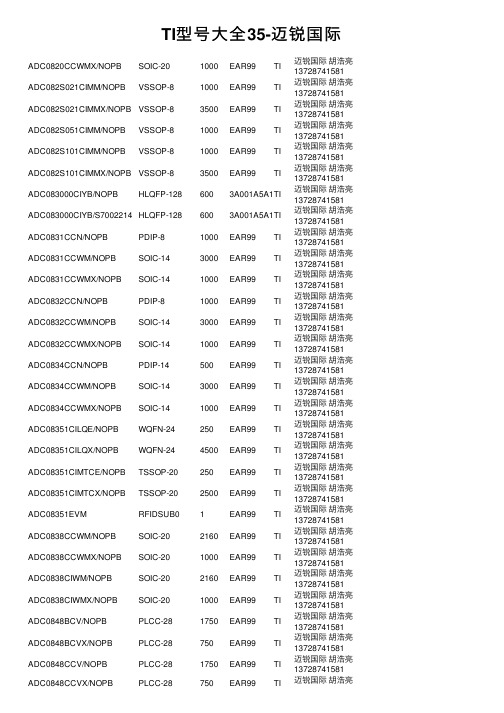
TI型号⼤全35-迈锐国际ADC0820CCWMX/NOPB SOIC-201000EAR99TI迈锐国际胡浩亮137********ADC082S021CIMM/NOPB VSSOP-81000EAR99TI迈锐国际胡浩亮137********ADC082S021CIMMX/NOPB VSSOP-83500EAR99TI迈锐国际胡浩亮137********ADC082S051CIMM/NOPB VSSOP-81000EAR99TI迈锐国际胡浩亮137********ADC082S101CIMM/NOPB VSSOP-81000EAR99TI迈锐国际胡浩亮137********ADC082S101CIMMX/NOPB VSSOP-83500EAR99TI迈锐国际胡浩亮137********ADC083000CIYB/NOPB HLQFP-1286003A001A5A1TI迈锐国际胡浩亮137********ADC083000CIYB/S7002214HLQFP-1286003A001A5A1TI迈锐国际胡浩亮137********ADC0831CCN/NOPB PDIP-81000EAR99TI迈锐国际胡浩亮137********ADC0831CCWM/NOPB SOIC-143000EAR99TI迈锐国际胡浩亮137********ADC0831CCWMX/NOPB SOIC-141000EAR99TI迈锐国际胡浩亮137********ADC0832CCN/NOPB PDIP-81000EAR99TI迈锐国际胡浩亮137********ADC0832CCWM/NOPB SOIC-143000EAR99TI迈锐国际胡浩亮137********ADC0832CCWMX/NOPB SOIC-141000EAR99TI迈锐国际胡浩亮137********ADC0834CCN/NOPB PDIP-14500EAR99TI迈锐国际胡浩亮137********ADC0834CCWM/NOPB SOIC-143000EAR99TI迈锐国际胡浩亮137********ADC0834CCWMX/NOPB SOIC-141000EAR99TI迈锐国际胡浩亮137********ADC08351CILQE/NOPB WQFN-24250EAR99TI迈锐国际胡浩亮137********ADC08351CILQX/NOPB WQFN-244500EAR99TI迈锐国际胡浩亮137********ADC08351CIMTCE/NOPB TSSOP-20250EAR99TI迈锐国际胡浩亮137********ADC08351CIMTCX/NOPB TSSOP-202500EAR99TI迈锐国际胡浩亮137********ADC08351EVM RFIDSUB01EAR99TI迈锐国际胡浩亮137********ADC0838CCWM/NOPB SOIC-202160EAR99TI迈锐国际胡浩亮137********ADC0838CCWMX/NOPB SOIC-201000EAR99TI迈锐国际胡浩亮137********ADC0838CIWM/NOPB SOIC-202160EAR99TI迈锐国际胡浩亮137********ADC0838CIWMX/NOPB SOIC-201000EAR99TI迈锐国际胡浩亮137********ADC0848BCV/NOPB PLCC-281750EAR99TI迈锐国际胡浩亮137********ADC0848BCVX/NOPB PLCC-28750EAR99TI迈锐国际胡浩亮137********ADC0848CCV/NOPB PLCC-281750EAR99TI迈锐国际胡浩亮137******** ADC0848CCVX/NOPB PLCC-28750EAR99TI迈锐国际胡浩亮137********ADC084S021CIMM/J7001218VSSOP-101000EAR99TI迈锐国际胡浩亮137********ADC084S021CIMM/NOPB VSSOP-101000EAR99TI迈锐国际胡浩亮137********ADC084S021CIMMX/NOPB VSSOP-103500EAR99TI迈锐国际胡浩亮137********ADC084S051CIMM/NOPB VSSOP-101000EAR99TI迈锐国际胡浩亮137********ADC084S101CIMM/NOPB VSSOP-101000EAR99TI迈锐国际胡浩亮137********ADC08500CIYB/NOPB HLQFP-1286003A991C1TI迈锐国际胡浩亮137********ADC08831IM SOIC-89500EAR99TI迈锐国际胡浩亮137********ADC08831IM/NOPB SOIC-89500EAR99TI迈锐国际胡浩亮137********ADC08831IMX/NOPB SOIC-82500EAR99TI迈锐国际胡浩亮137********ADC08832IMM/NOPB VSSOP-81000EAR99TI迈锐国际胡浩亮137********ADC08832IM/NOPB SOIC-89500EAR99TI迈锐国际胡浩亮137********ADC08832IMX/NOPB SOIC-82500EAR99TI迈锐国际胡浩亮137********ADC088S022CIMT TSSOP-169200EAR99TI迈锐国际胡浩亮137********ADC088S022CIMT/NOPB TSSOP-169200EAR99TI迈锐国际胡浩亮137********ADC088S022CIMTX/NOPB TSSOP-162500EAR99TI迈锐国际胡浩亮137********ADC088S052CIMT/NOPB TSSOP-169200EAR99TI迈锐国际胡浩亮137********ADC088S052CIMTX/NOPB TSSOP-162500EAR99TI迈锐国际胡浩亮137********ADC088S102CIMT/NOPB TSSOP-169200EAR99TI迈锐国际胡浩亮137********ADC088S102CIMTX/NOPB TSSOP-162500EAR99TI迈锐国际胡浩亮137********ADC08B200CIVS/NOPB TQFP-482500EAR99TI迈锐国际胡浩亮137********ADC08B200QCIVS/NOPB TQFP-482500EAR99TI迈锐国际胡浩亮137********ADC08B3000CIYB/NOPB HLQFP-1286003A991C1TI迈锐国际胡浩亮137********ADC08B3000RB/NOPB RFIDSUB01EAR99TI迈锐国际胡浩亮137********ADC08D1000CIYB/NOPB HLQFP-1286003A001A5A1TI迈锐国际胡浩亮137********ADC08D1010DIYB/NOPB HLQFP-1286003A001A5A1TI迈锐国际胡浩亮137********ADC08D1020CIYB/NOPB HLQFP-1286003A001A5A1TI迈锐国际胡浩亮137********ADC08D1500CIYB/NOPB HLQFP-1286003A001A5A1TI迈锐国际胡浩亮137********ADC08D1520CIYB/NOPB HLQFP-1286003A001A5A1TI迈锐国际胡浩亮137********ADC08D1520CIYB/S7002396HLQFP-1286003A001A5A1TI迈锐国际胡浩亮137********ADC08D1520CVAL RFIDSUB013A002H1A TI迈锐国际胡浩亮137********迈锐国际胡浩亮ADC08D1520RB/NOPB RFIDSUB013A002H1A TI137******** ADC08D1520WGFQV CQFP-128243A001A2C TI迈锐国际胡浩亮137********ADC08D1520WGMPR CQFP-128243A001A5A1TI迈锐国际胡浩亮137********ADC08D500CIYB/NOPB HLQFP-1286003A991C1TI迈锐国际胡浩亮137********ADC08D500CIYB/S7002554HLQFP-1286003A991C1TI迈锐国际胡浩亮137********ADC08D500CIYB/S7002952HLQFP-1286003A991C1TI迈锐国际胡浩亮137********ADC08D502CIYB/NOPB HLQFP-1286003A991C1TI迈锐国际胡浩亮137********ADC08DJ3200AAV FCBGA-1448403A001A5A1TI迈锐国际胡浩亮137********ADC08DJ3200AAVT FCBGA-1442503A001A5A1TI迈锐国际胡浩亮137********ADC08DJ3200EVM UNKNOWN-14413A002H1A TI迈锐国际胡浩亮137********ADC08DL500CIVV/NOPB LQFP-1446003A991C1TI迈锐国际胡浩亮137********ADC08DL502CIVV/NOPB LQFP-1446003A991C1TI迈锐国际胡浩亮137********ADC08L060CIMT/NOPB TSSOP-246100EAR99TI迈锐国际胡浩亮137********ADC08L060CIMTX/NOPB TSSOP-242500EAR99TI迈锐国际胡浩亮137********ADC08L060EVM RFIDSUB01EAR99TI迈锐国际胡浩亮137********ADC09QJ1300EVM RFIDSUB01EAR99TI迈锐国际胡浩亮137********ADC10040CIMT/NOPB TSSOP-284800EAR99TI迈锐国际胡浩亮137********ADC10040CIMTX/NOPB TSSOP-282500EAR99TI迈锐国际胡浩亮137********ADC10040QCIMT/NOPB TSSOP-284800EAR99TI迈锐国际胡浩亮137********ADC10040QCIMTX/NOPB TSSOP-282500EAR99TI迈锐国际胡浩亮137********ADC10065CIMT/NOPB TSSOP-284800EAR99TI迈锐国际胡浩亮137********ADC10065CIMTX/NOPB TSSOP-282500EAR99TI迈锐国际胡浩亮137********ADC10080CIMT/NOPB TSSOP-284800EAR99TI迈锐国际胡浩亮137********ADC10080CIMTX/NOPB TSSOP-282500EAR99TI迈锐国际胡浩亮137********ADC101C021CIMK/NOPB SOT-23-THN-61000EAR99TI迈锐国际胡浩亮137********ADC101C021CIMKX/NOPB SOT-23-THN-63000EAR99TI迈锐国际胡浩亮137********ADC101C021CIMM/NOPB VSSOP-81000EAR99TI迈锐国际胡浩亮137********ADC101C027CIMK/NOPB SOT-23-THN-61000EAR99TI迈锐国际胡浩亮137********ADC101C027CIMKX/NOPB SOT-23-THN-63000EAR99TI迈锐国际胡浩亮137********ADC101S021CIMF/NOPB SOT-23-61000EAR99TI迈锐国际胡浩亮137********ADC101S021CIMFX/NOPB SOT-23-63000EAR99TI迈锐国际胡浩亮137********迈锐国际胡浩亮ADC101S021CISD/NOPB WSON-61000EAR99TI137********ADC101S021CISDX/NOPB WSON-64500EAR99TI迈锐国际胡浩亮137********ADC101S051CIMF/NOPB SOT-23-61000EAR99TI迈锐国际胡浩亮137********ADC101S051CIMFX/NOPB SOT-23-63000EAR99TI迈锐国际胡浩亮137********ADC101S051QIMF/NOPB SOT-23-61000EAR99TI迈锐国际胡浩亮137********ADC101S051QIMFX/NOPB SOT-23-63000EAR99TI迈锐国际胡浩亮137********ADC101S101CIMF/NOPB SOT-23-61000EAR99TI迈锐国际胡浩亮137********ADC101S101CIMFX/NOPB SOT-23-63000EAR99TI迈锐国际胡浩亮137********ADC101S101CISD/NOPB WSON-61000EAR99TI迈锐国际胡浩亮137********。
ABB--隔离开关
ABB丨开关类产品丨1SXF300001C2001 2/2
SwitchLine隔离开关 产品一览表(16...4000A)
开关规格
A
IEC
lth
A
le /AC22A , 415V A
2
le /AC23A , 415V A le /DC21, 660V A
le /DC21, 1000V A
le /DC21, 1200V A
附件
附件概览
3/18
手柄
3/19
加长轴
3/21
辅助触头
3/22
第4极和中性极、硬连接片
3/23
端子罩、相隔板
3/24
标签板、保护插件、端子线夹、绝缘板、铜铝电缆端子线夹 3/25
正面操作的组合开关转换套件
3/27
锁紧附件
3/27
熔断器监测器、熔断器指示器(DPMM)
3/28
机械联锁套件和电气联锁、线圈
操作方式 E : IEC标准 - 正面操作 ES : IEC标准 - 侧面操作(只适用于OT200-800) U : UL/CSA标准
电流等级(A) 200、250、315、400、630、800、1000、1250、1600、2000、2500、3200、4000
隔离开关型号
ABB丨开关类产品丨1SXF300001C2001 2/6
OTDC16F OTDC25F OTDC32F
OTDC100E OTDC160E OTDC200E OTDC250E OTDC315 OTDC400 OTDC100U OTDC200U OTDC250U OTDC320U OTDC400U
OT16F OT25F OT40F
OT16F OT25F OT40F
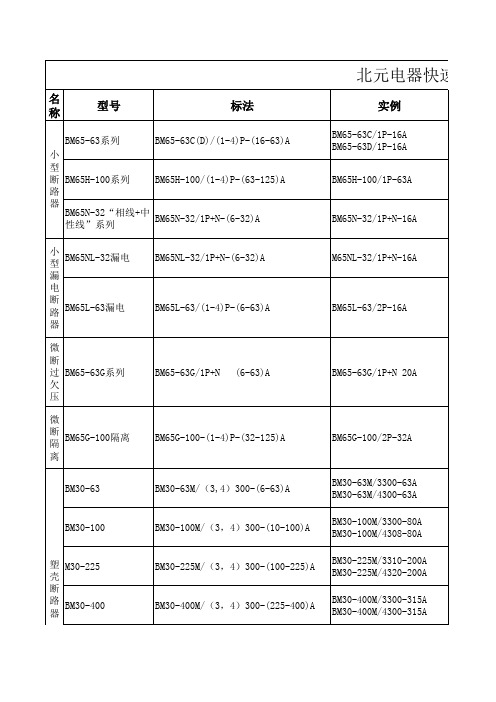
北元电器快速选型表
型号
标法
BM65-63系列
BM65-63C(D)/(1-4)P-(16-63)A
小
型
断 BM65H-100系列 BM65H-100/(1-4)P-(63-125)A
路
器
BM65N-32“相线+中 性线”系列
BM65N-32/1P+N-(6-32)A
北元电器快速选型表
实例
BM65-63C/1P-16A BM65-63D/1P-16A
BM30E-100/3400 -(10-100)A
BM30L-100/3400B-80A
BM30E-225/3400-(100-250)A BM30E-400/3400-(200-400)A BM30E-630/3400-(400-630)A
BM30L-225/3400B-200A BM30L-400/3400B-350A BM30L-630/3400B-500A
过载、短路、漏电 保护
用于交流50Hz线路,230V
6A、10A、16A、20A、 对建筑和类似场所
25A、32A、40A、50A、 有过载,短路,过 用于交流50Hz线路,230V
63A
欠压保护。
32A、63A、80A、100A、 隔离
用于交流50Hz或60Hz线路,400V以下
6A、10A、16A、20A、 25A、32A、40A、50A、 63A
操作和柜外操作
故障危害。
4000A、5000A、6300A
M65NL-32/1P+N-16A BM65L-63/2P-16A BM65-63G/1P+N 20A BM65G-100/2P-32A
BM30-63
BM30-63M/(3,4)300-(6-63)A
AGMA Standards-美国齿轮标准
AGMA 217.01AGMA 900-H06AGMA 901-A92AGMA 904-C96AGMA 908-B89AGMA 910-C90AGMA 911-A94AGMA 912-A04AGMA 913-A98AGMA 914-B04AGMA 915-1-A02AGMA 915-2-A05AGMA 915-3-A99-1999AGMA 917-B97AGMA 918-A93AGMA 920-A01AGMA 922-A96AGMA 923-B05AGMA 925-A03AGMA 926-C99-1999AGMA 927-A01AGMA 930-A05AGMA 931-A02AGMA 932-A05AGMA 933-B03AGMA 935-A05AGMA 938-A05AGMA ISO 10064-1AGMA ISO 10064-2AGMA ISO 10064-5-A06 AGMA ISO 14179-1ANSI/AGMA 1003-G93 (R1999) ANSI/AGMA 1006-A97 (R2003) ANSI/AGMA 1010-E95 (R2004) ANSI/AGMA 1012-2005ANSI/AGMA 1102-A03ANSI/AGMA 1106-A97 (R2003) ANSI/AGMA 2000-A88ANSI/AGMA 2001-D04ANSI/AGMA 2002-B88 (R1996) ANSI/AGMA 2003-B97 (R2003) ANSI/AGMA 2004-B89 (R2006) ANSI/AGMA 2005-D03ANSI/AGMA 2007-C00ANSI/AGMA 2008-C01ANSI/AGMA 2009-B01ANSI/AGMA 2011-A98ANSI/AGMA 2015-1-A01ANSI/AGMA 2015-2-A06ANSI/AGMA 2101-D04ANSI/AGMA 2111-A98ANSI/AGMA 2116-A05ANSI/AGMA 6000-B96 (R2002) ANSI/AGMA 6001-D97 (R2003) ANSI/AGMA 6002-B93 (R2001) ANSI/AGMA 6004-F88 (R1996)ANSI/AGMA 6005-B89 (R1996) ANSI/AGMA 6008-A98ANSI/AGMA 6011-I03ANSI/AGMA 6013-A06ANSI/AGMA 6022-C93 (R2000) ANSI/AGMA 6023-A88 (R2000) ANSI/AGMA 6025-D98ANSI/AGMA 6033-B98ANSI/AGMA 6034-B92 (R1999) ANSI/AGMA 6035-2002ANSI/AGMA 6113-A06ANSI/AGMA 6123-A06ANSI/AGMA 6133-B98ANSI/AGMA 6135-2002ANSI/AGMA 9000-C90 (R2001) ANSI/AGMA 9001-B97 (R2003) ANSI/AGMA 9002-B04ANSI/AGMA 9003-A91 (R1999) ANSI/AGMA 9004-A99ANSI/AGMA 9005-E02ANSI/AGMA 9008-B00 (R2006) ANSI/AGMA 9009-D02ANSI/AGMA 9112-A04ANSI/AGMA ISO 1328-1ANSI/AGMA ISO 1328-2ANSI/AGMA ISO 18653-A06ANSI/AGMA/AWEA 6006-A03 Supplemental Tables for AGMA 2015 AGMA 6006-A03ANSI/AGMA 6009-A00ANSI/AGMA 6109-A00ANSI/AGMA 6110-F97 (R2003)Information Sheet - Gear Scoring Design for Aerospace Spur and Helical Power GearsStyle Manual for the Preparation of Standards, Information Sheets and Editorial ManualsA Rational Procedure for the Preliminary Design of Minimum Volume GearsMetric UsageInformation Sheet - Geometry Factors for Determining the Pitting Resistance and Bending Strength of Spur, HelicFormats for Fine-Pitch Gear Specification DataDesign Guidelines for Aerospace GearingMechanisms of Gear Tooth FailureMethod for Specifying the Geometry of Spur and Helical GearsGear Sound Manual - Part I: Fundamentals of Sound as Related to Gears; Part II: Sources, Specifications and Levels of G Inspection Practices - Part 1: Cylindrical Gears - Tangential MeasurementsInspection Practices - Part 2: Cylindrical Gears - Radial MeasurementsInspection Practices - Gear Blanks, Shaft Center Distance and Parallelism"Design Manual for Parallel Shaft Fine-Pitch GearingA Summary of Numerical Examples Demonstrating the Procedures for Calculating Geometry Factors for Spur an Materials for Plastic GearsLoad Classification and Service Factors for Flexible CouplingsMetallurgical Specifications for Steel GearingEffect of Lubrication on Gear Surface DistressRecommended Practice for Carburized Aerospace GearingLoad Distribution Factors - Analytical Methods for Cylindrical GearsCalculated Bending Load Capacity of Powder Metallurgy (P/M) External Spur GearsCalibration of Gear Measuring Instruments and Their Application to the Inspection of Product GearsRating the Pitting Resistance and Bending Strength of Hypoid GearsBasic Gear GeometryRecommendations Relative to the Evaluation of Radial Composite Gear Double Flank TestersShot Peening of GearsCylindrical Gears - Code of Inspection Practice - Part 1: Inspection of Corresponding Flanks of Gear TeethCylindrical Gears - Code of Inspection Practice - Part 2: Inspection Related to Radial Composite Deviations, Runout, Tooth Code of Inspection Practice - Part 5: Recommendations Relative to Evaluation of Gear Measuring InstrumentsGear Reducers - Thermal Capacity Based on ISO/TR 14179-1Tooth Proportions for Fine-Pitch Spur and Helical GearingTooth Proportions for Plastic GearsAppearance of Gear Teeth - Terminology of Wear and FailureGear Nomenclature, Definitions of Terms with SymbolsTolerance Specification for Gear HobsTooth Proportions for Plastic Gears (Metric Version of ANSI/AGMA 1006-A97)Gear Classification and Inspection Handbook - Tolerances and Measuring Methods for Unassembled Spur and H Fundamental Rating Factors and Calculation Methods for Involute Spur and Helical Gear TeethTooth Thickness Specification and MeasurementRating the Pitting Resistance and Bending Strength of Generated Straight Bevel, Zerol Bevel and Spiral Bevel Gear Teeth Gear Materials and Heat Treatment ManualDesign Manual for Bevel GearsGears - Surface Temper Etch Inspection After GrindingAssembling Bevel GearsBevel Gear Classification, Tolerances and Measuring MethodsCylindrical Wormgearing Tolerance and Inspection MethodsAccuracy Classification System - Tangential Measurements for Cylindrical GearsAccuracy Classification System - Radial Measurements for Cylindrical GearsFundamental Rating Factors and Calculation Methods for Involute Spur and Helical Gear Teeth (Metric Edition) Cylindrical Wormgearing Tolerance and Inspection Methods (Metric)Evaluation of Double Flank Testers for Radial Composite Measurement of GearsSpecification for Measurement of Linear Vibration on Gear UnitsDesign and Selection of Components for Enclosed Gear DrivesDesign Guide for Vehicle Spur and Helical GearsGear Power Rating for Cylindrical Grinding Mills, Kilns, Coolers, and DryersPower Rating for Helical and Herringbone Gearing for Rolling Mill ServiceSpecifications for Powder Metallurgy GearsSpecification for High Speed Helical Gear UnitsStandard for Industrial Enclosed Gear DrivesDesign Manual for Cylindrical WormgearingDesign Manual for Enclosed Epicylic Gear DrivesSound for Enclosed Helical, Herringbone, and Spiral Bevel Gear DrivesMarine Propulsion Gear Units, Part 1 - MaterialsPractice for Enclosed Cylindrical Wormgear Speed Reducers and GearmotorsDesign, Rating and Application of Industrial Globoidal WormgearingStandard for Industrial Enclosed Gear Drives (Metric Edition)Design Manual for Enclosed Epicyclic Gear DrivesMaterials for Marine Propulsion GearingDesign, Rating and Application of Industrial Globoidal Wormgearing (Metric Edition)Flexible Couplings - Potential Unbalance ClassificationFlexible Couplings - LubricationBores and Keyways for Flexible Couplings (Inch Series)Flexible Couplings - Keyless FitsFlexible Couplings - Mass Elastic Properties and Other CharacteristicsIndustrial Gear LubricationFlexible Couplings - Gear Type - Flange Dimensions, Inch Series (Also listed as 9008-B99)Flexible Couplings - Nomenclature for Flexible CouplingsBores and Keyways for Flexible Couplings (Metric Series)Cylindrical Gears - ISO System of Accuracy - Part 1: Definitions and Allowable Values of Deviations Relevant to Correspon Cylindrical Gears - ISO System of Accuracy - Part 2: Definitions and Allowable Values of Deviations Relevant to Radial Co Gears - Evaluation of Instruments for the Measurement of Individual GearsDesign and Specification of Gearboxes for Wind TurbinesAccuracy Classification System - Tangential Measurement Tolerance Tables for Cylindrical GearsStandard for Design and specification of Gearbox for Wind Turbines (Spersedes AGMA 921 - A97)Standard for Gearmotor, Shaft Mounted and Screw Conveyor DrivesStandard for Gearmotor, Shaft Mounted and Screw Conveyor Drives (metric version)Spur, Helical, Herringbone, and Bevel Enclosed DrivesAGMA Technical CommitteeAGMA Technical CommitteeAGMA Technical CommitteeAGMA Technical CommitteeAGMA Technical CommitteeAGMA Technical Committeecifications and Levels of Gear Sound; Part III: Gear Noise ControlAGMA Technical CommitteeAGMA Technical CommitteeDeviations, Runout, Tooth Thickness and BacklashInstrumentsAGMAAGMASpiral Bevel Gear TeethAGMAAGMAAGMAMetric Edition)AGMAAGMAAGMAAGMAAGMAAGMAAGMAns Relevant to Corresponding Flanks of Gear Teethns Relevant to Radial Composite Deviations and Runout Information in GE libraries while not listed herelisted in sheet ver3 while missed in ver4listed in sheet ver3 while missed in ver4listed in sheet ver3 while missed in ver4AGMA+217.01.pdf46 AGMA+900-H06.pdf30 AGMA+901-A92.pdf42 AGMA+904-C96.pdf42 AGMA+908-B89.pdf84 AGMA+910-C90.pdf51 AGMA+911-A94.pdf96 AGMA+912-A04.pdf70 AGMA+913-A98.pdf58 AGMA+914-B04.pdf76 AGMA+915-1-A02.pdf105 AGMA+915-2-A05.pdf47 AGMA+915-3-A99-1999.pdf42 AGMA+917-B97+.pdf84 AGMA+918-A93.pdf68 AGMA+920-A01.pdf58 AGMA+922-A96.pdf42 AGMA+923-B05.pdf79 AGMA+925-A03.pdf69 AGMA+926-C99-1999.pdf48 AGMA+927-A01.pdf69 AGMA+930-A05.pdf83 AGMA+931-A02.pdf63 AGMA+932-A05.pdf60 AGMA+933-B03.pdf37 AGMA+935-A05.pdf40 AGMA+938-A05.pdf45 AGMA+ISO+10064-1.pdf75 AGMA+ISO+10064-2.pdf55 AGMA+ISO+10064-5-A06.pdf145 AGMA+ISO+14179-1.pdf69 ANSI+AGMA+1003-G93+(R1999).pdf68 ANSI+AGMA+1006-A97+(R2003).pdf68 ANSI+AGMA+1010-E95+(R2004).pdf96 ANSI+AGMA+1012-2005.pdf82 ANSI+AGMA+1102-A03.pdf82 ANSI+AGMA+1106-A97+(R2003).pdf62 ANSI+AGMA+2000-A88.pdf140 ANSI+AGMA+2001-D04.pdf167 ANSI+AGMA+2002-B88+(R1996).pdf90 ANSI+AGMA+2003-B97+(R2003).pdf145 ANSI+AGMA+2004-B89+(R2006).pdf96 ANSI+AGMA+2005-D03.pdf167 ANSI+AGMA+2007-C00.pdf37 ANSI+AGMA+2008-C01.pdf68 ANSI+AGMA+2009-B01.pdf101 ANSI+AGMA+2011-A98.pdf84 ANSI+AGMA+2015-1-A01.pdf84 ANSI+AGMA+2015-2-A06.pdf40 ANSI+AGMA+2101-D04.pdf140 ANSI+AGMA+2111-A98.pdf74 ANSI+AGMA+2116-A05.pdf38 ANSI+AGMA+6000-B96+(R2002).pdf73 ANSI+AGMA+6001-D97+(R2003).pdf84 ANSI+AGMA+6002-B93+(R2001).pdf68 ANSI+AGMA+6004-F88+(R1996).pdf84ANSI+AGMA+6005-B89+(R1996).pdf79 ANSI+AGMA+6008-A98.pdf56 ANSI+AGMA+6011-I03.pdf95 ANSI+AGMA+6013-A06.pdf159 ANSI+AGMA+6022-C93+(R2000).pdf73 ANSI+AGMA+6023-A88+(R2000).pdf84 ANSI+AGMA+6025-D98.pdf79 ANSI+AGMA+6033-B98.pdf84 ANSI+AGMA+6034-B92+(R1999).pdf56 ANSI+AGMA+6035-2002.pdf79 ANSI+AGMA+6113-A06.pdf135 ANSI+AGMA+6123-A06.pdf140 ANSI+AGMA+6133-B98.pdf74 ANSI+AGMA+6135-2002.pdf74 ANSI+AGMA+9000-C90+(R2001).pdf62 ANSI+AGMA+9001-B97+(R2003).pdf42 ANSI+AGMA+9002-B04.pdf55 ANSI+AGMA+9003-A91+(R1999).pdf51 ANSI+AGMA+9004-A99.pdf69 ANSI+AGMA+9005-E02.pdf84 ANSI+AGMA+9008-B00+(R2006).pdf38 ANSI+AGMA+9009-D02.pdf49 ANSI+AGMA+9112-A04.pdf53 ANSI+AGMA+ISO+1328-1.pdf63 ANSI+AGMA+ISO+1328-2.pdf42 ANSI+AGMA+ISO+18653-A06.pdf75 ANSI+AGMA+AWEA+6006-A03.pdf208 Supplemental+Tables+for+AGMA+20137。
MU70-SU0 LGA2011插座R3主板 用户手册说明书
2-3-6-1 IOAT 配置...................................................................................................84
-3-
第3章
2-3-2-3 CPU T State Control(CPU T 状态控制)............................................73
2-3-3 Common RefCode Configuration(通用 RefCode 配置)..............74
2-3-5-1 内存拓扑.....................................................................................................79
2-3-5-2 内存热效应................................................................................................80
目录
包装箱物品...........................................................................................................5 MU70-SU0 主板布局..........................................................................................6 框图.......................................................................................................................9 第 1 章 硬件安装.............................................................................................10
铝合金牌号对照
2117(A-U2G)
1199/A91199 1098/A91098 1185/A91185 1350A 2117
EN AW-2024/AlCu4Mg1 EN AW-2014/AlCu4Mg EN AW-2019/AlCu6Mn
AlCuMg1/3.1325 AlCuMg2/3.1355 AlCuSiMn/3.1255
AlMg1(B)
A5005
EN AW-5556A/AlMgMn EN AW-5051A/AlMg2(B) EN AW-5005/AlMg1(B)
5556A(NG61) AlMg1.8/3.3326 5005(A-G0.6) 5005(N41)
EN AW-2319/AlCu6Mn(A)
AlCu6BiPb AlCu4SiMg AlCu4SiMg(A) AlCu4MgSi AlCu4MgSi(A)
24345
EN AW-2011/AlCu6BiPb EN AW-2014/AlCu4SiMg EN AW-2014/AlCu4SiMg(A) EN AW-2017A/AlCu4MgSi(A)
ISO(欧盟)
Al 99.5 Al 99.6 Al 99.7 Al 99.0Cu Al 99.0 E-Al99.5 E-Al99.7 Al 99.3
日本
A1050 A1060 A1070
印度
19500 19600 19700
俄罗斯
A6 A7
EN(欧洲)
EN AW-1050A/Al99.5 EN AW-1060/Al99.6 EN AW-1070A/Al99.7 EN AW-1100/Al99.0Cu EN AW-1200/Al99.0 EN AW-1350/E-Al99.5 EN AW-1370/E-Al99.7 EN AW-1050A/Al99.5
林肯电气(Lincoln Electric)机械组装说明书

1 XX
1 FEED PLATE
0744-000-178R
1 XX
2 FIXING ARM COMPL.
0646-233-015R
1 XX
3 AXIS DRIVE ROLL L
0646-233-039R
1 XX
Spare Parts - Electrical Schematic
2
Spare Parts - Electrical Schematic
ASSEMBLY PAGE NAME
CODE NO.: 50215 50216
K NO.: K10406 K10407
FIGURE NO.: LINC FEED 37 LINC FEED 38
A
B
1
1
2
2
39 38 37 36 33 10
12
11 9
2
7
6
5
8
1
4
27
3
28
16 13
17 34 35
18 19 15
14
15 20
22
25
26 21
29
30 31 3
32
24 23
Figure A
Figure A: Machine Assembly
Item Description
Part Number
QTY 1 2 3 4 5 6 7
1 FRONT PANEL
R-3019-016-1/08R
1 XX
1 XX
1 XX 1 XX 3 XX 1 XX 1 XX 1 XX 1 XX 1 XX 1 XX 1 XX 1 XX 1 XX 1 XX 1 XX 1 XX 1 XX 1 XX 1 XX 1 XX 1 XX 1 XX 1 XX 1 XX 1 XX 1 XX 1 XX 1 XX 1 XX 1 XX
ATR7039-PESG中文资料
Features•Input Frequency Range 2.7 GHz to 3.0 GHz •POUTTypically 12 dBm at 5.8 GHz•PINTypically 0 dBm•VCC3.0V to 3.9V•CW Mode Operation•Package: QFN16Benefits•Ramping Control Extends Battery Lifetime •AC Input Coupling Saves External Capacitors •Extremely Low BOM for ApplicationElectrostatic sensitive device.Observe precautions for handling.1.DescriptionThe 5.8-GHz frequency doubler IC is designed with Atmel’s Silicon-Germanium (SiGe) process and provides a high conversion gain.The device consists of a doubler stage, a filter and a driver amplifier with an output power of 11 dBm. The output stage was realized using an open-collector structure. Power-up/down and output levels are controlled via the bias control pin 6 and pin 7 (V CTL).TM24786E–DECT–10/05ATR7039 [Preliminary]Figure 1-1.Block Diagram34786E–DECT–10/05ATR7039 [Preliminary]2.Pin ConfigurationFigure 2-1.Pinning QFN16Table 2-1.Pin DescriptionPin Symbol Function 1GND Ground 2NC Not connected 3RFIN RF input 4GND Ground 5GND Ground6VCTL1Power-up/biasing control voltage to frequency doubler stage 7VCTL2Power-up/biasing control voltage to output amplifier stage 8GND Ground 9GND Ground 10RFOUT RF output 11RFOUT RF output 12GND Ground13VCC2Supply voltage for output amplifier stage 14GND Ground15VCC1Supply voltage for frequency doubler stage 16VCC_CTLSupply voltage for biasing controlPaddle– Ground44786E–DECT–10/05ATR7039 [Preliminary]3.Absolute Maximum RatingsStresses beyond those listed under “Absolute Maximum Ratings” may cause permanent damage to the device. This is a stress rating only and functional operation of the device at these or any other conditions beyond those indicated in the operational sections of this specification is not implied. Exposure to absolute maximum rating conditions for extended periods may affect device reliability.ParametersSymbol Value Unit Supply voltage, no RF V CC 5V Supply current I CC 400mA Junction temperature T j 150°C Storage temperature T Stg –40 to +125°C Input RF powerP IN13dBm Control voltage V CTL1,2 2.5V4.Thermal ResistanceParametersSymbol Value Unit Junction ambient QFN16 package, slug soldered on PCBR thJA40K/W5.Operating RangeParameters Symbol Value Unit Supply voltage V CC 3.0 to 3.9 V Input frequency range f in 2700 to 3000 MHz Output frequency range f out 5400 to 6000 MHz Ambient temperature rangeT amb–25 to +75°C54786E–DECT–10/05ATR7039 [Preliminary]6.Electrical CharacteristicsNo.Parameters Test ConditionsPin Symbol Min.Typ.Max.Unit Type*1.0Input power3Pin 010dBm A 1.1Output power Measured at harmonic frequency 2f10, 11P2f 12dBm A 1.2Measured at harmonic frequency 3f10, 11P3f -8dBm A 1.3Measured atfundamental frequency 10, 11P1f TBDdBm A 1.4Output power deviation Measured at harmonic frequency 10, 11P d –2+2dB A 1.5Control voltage rangeDoubler operating mode6V CTL1 1.4V A 7V CTL2 1.7V A 1.6Power down mode6, 7V CTL1,20.2V A 1.7Input and output returnlossWith external matching3, 10, 11–12–8dB C 1.8Reverse isolation 2f3, 10, 11ISO r 3036dB C 1.9Current consumptionfor 12dBm output power 13, 15, 16I CC 90mA A 1.10Current consumption inpower down mode V CTL1,2 ≤0.2V 13, 15, 16I CC15µA A 2.0Duty cycle100%C*) Type means: A = 100% tested, B = 100% correlation tested, C = Characterized on samples, D = Design parameter64786E–DECT–10/05ATR7039 [Preliminary]7.Application Circuit74786E–DECT–10/05ATR7039 [Preliminary]9.Package Information8.Ordering InformationExtended Type Number Package RemarksATR7039-PESG QFN16 - 4x4Tube, MOQ 750, Pb-freeATR7039-PEQGQFN16 - 4x4Taped and reeled, MOQ 6000, Pb-free4786E–DECT–10/05© Atmel Corporation 2005. All rights reserved. Atmel ®, logo and combinations thereof, Everywhere You Are ® and others, are registered trade-marks or trademarks of Atmel Corporation or its subsidiaries. Other terms and product names may be trademarks of others.Disclaimer: The information in this document is provided in connection with Atmel products. No license, express or implied, by estoppel or otherwise, to any intellectual property right is granted by this document or in connection with the sale of Atmel products. EXCEPT AS SET FORTH IN ATMEL ’S TERMS AND CONDI-TIONS OF SALE LOCATED ON ATMEL ’S WEB SITE, ATMEL ASSUMES NO LIABILITY WHATSOEVER AND DISCLAIMS ANY EXPRESS, IMPLIED OR STATUTORY WARRANTY RELATING TO ITS PRODUCTS INCLUDING, BUT NOT LIMITED TO, THE IMPLIED WARRANTY OF MERCHANTABILITY, FITNESS FOR A PARTICULAR PURPOSE, OR NON-INFRINGEMENT. IN NO EVENT SHALL ATMEL BE LIABLE FOR ANY DIRECT, INDIRECT, CONSEQUENTIAL, PUNITIVE, SPECIAL OR INCIDEN-TAL DAMAGES (INCLUDING, WITHOUT LIMITATION, DAMAGES FOR LOSS OF PROFITS, BUSINESS INTERRUPTION, OR LOSS OF INFORMATION) ARISING OUT OF THE USE OR INABILITY TO USE THIS DOCUMENT, EVEN IF ATMEL HAS BEEN ADVISED OF THE POSSIBILITY OF SUCH DAMAGES. Atmel makes no representations or warranties with respect to the accuracy or completeness of the contents of this document and reserves the right to make changes to specifications and product descriptions at any time without notice. Atmel does not make any commitment to update the information contained herein. Unless specifically provided otherwise, Atmel products are not suitable for, and shall not be used in, automotive applications. Atmel’s products are not intended, authorized, or warranted for use as components in applications intended to support or sustain life.Atmel CorporationAtmel Operations2325 Orchard Parkway San Jose, CA 95131, USA Tel: 1(408) 441-0311Fax: 1(408) 487-2600Regional HeadquartersEuropeAtmel SarlRoute des Arsenaux 41Case Postale 80CH-1705 Fribourg SwitzerlandTel: (41) 26-426-5555Fax: (41) 26-426-5500AsiaRoom 1219Chinachem Golden Plaza 77 Mody Road Tsimshatsui East Kowloon Hong KongTel: (852) 2721-9778Fax: (852) 2722-1369Japan9F, Tonetsu Shinkawa Bldg.1-24-8 ShinkawaChuo-ku, Tokyo 104-0033JapanTel: (81) 3-3523-3551Fax: (81) 3-3523-7581Memory2325 Orchard Parkway San Jose, CA 95131, USA Tel: 1(408) 441-0311Fax: 1(408) 436-4314Microcontrollers2325 Orchard Parkway San Jose, CA 95131, USA Tel: 1(408) 441-0311Fax: 1(408) 436-4314La Chantrerie BP 7060244306 Nantes Cedex 3, France Tel: (33) 2-40-18-18-18Fax: (33) 2-40-18-19-60ASIC/ASSP/Smart CardsZone Industrielle13106 Rousset Cedex, France Tel: (33) 4-42-53-60-00Fax: (33) 4-42-53-60-011150 East Cheyenne Mtn. Blvd.Colorado Springs, CO 80906, USA Tel: 1(719) 576-3300Fax: 1(719) 540-1759Scottish Enterprise Technology Park Maxwell BuildingEast Kilbride G75 0QR, Scotland Tel: (44) 1355-803-000Fax: (44) 1355-242-743RF/AutomotiveTheresienstrasse 2Postfach 353574025 Heilbronn, Germany Tel: (49) 71-31-67-0Fax: (49) 71-31-67-23401150 East Cheyenne Mtn. Blvd.Colorado Springs, CO 80906, USA Tel: 1(719) 576-3300Fax: 1(719) 540-1759Biometrics/Imaging/Hi-Rel MPU/ High Speed Converters/RF DatacomAvenue de Rochepleine BP 12338521 Saint-Egreve Cedex, France Tel: (33) 4-76-58-30-00Fax: (33) 4-76-58-34-80Literature Requests/literature。
海尔液晶电视进总线方法
海尔液晶电视进总线⽅法平板电视⼯⼚模式进⼊⽅法(⼀)、CPT机芯机器型号:P46C6A-A1、P46C3A-A1、P46C6A-A1(双⾊)VA模组等。
遥控器:HTR-050进总线⽅法:⽤遥控器多次按menu键,选择最后⼀个图标(?),按上下左右⽅向键,进⼊⼯⼚模式。
(⼆)、CPT机芯机器型号:P46C6A-A1(双⾊)VC模组等。
遥控器:HTR- 158进总线⽅法:⽤遥控器按menu键,再⽤左右⽅向键选择最后⼀个图标(?),在此页⾯下依次按9、4、4、3数字键,进⼊⼯⼚模式。
(三)、OPLUS 201机芯机器型号:P42S6A-C1(增强型)、P42S6A-C1(豪华型)、P42SV6-C1等。
遥控器:HTR-068进总线⽅法:按POWER键,使PDP处于待机状态,按MUTE+7+4+1,按POWER开机可进⼊⼯⼚模式(四)、OPLUS 203机芯机器型号:P42S6A-C1(双⾊)、P42A1-AK等。
遥控器:HTR-121、进总线⽅法:按POWER,使PDP处于待机状态,按MUTE+7+4+1,按POWER开机可进⼊⼯⼚模式(五)、OPLUS 203机芯机器型号:L48A9-AK、L46A9-AK遥控器:HTR-688进总线⽅法:按POWER,使PDP处于待机状态,按MUTE+7+4+1,按POWER开机可进⼊⼯⼚模式(六)、INDTEK机芯机器型号:P42SV6-C1(增强型)、P50V6-A8等。
遥控器:HTR-135进总线⽅法:使⽤本机遥控器“菜单”+“节⽬列表”+“静⾳”进⼊⼯⼚调试项。
(七)、PW112机芯机器型号:L176A-G1、L15L6A-G0等。
遥控器:HTR-052进总线⽅法:撕开遥控器前⾯板,靠近“POWER”键的按键为⼯⼚模式进⼊键。
(⼋)、PW1306机芯机器型号:L20AV6-A0、L20AV6-A0(时尚型)等。
遥控器:HTR-111进总线⽅法:撕开遥控器前⾯板,靠近“POWER”键的按键为⼯⼚模式进⼊键。
att7039 用户手册说明书
ATT7039 用户手册版本更新记录文件编号 版本 日期 修订 更改理由主要更改内容 ATT7039用户手册 V0.1 2010/06/25 yyuan 初稿ATT7039用户手册 V0.2 2010/07/10 yyuan 更新 1.更改存储器寻址空间2.添加引脚分布图ATT7039用户手册 V0.3 2010/07/15 yyuan 添加系统框图;更改EMUIE地址 1、在1.4节添加系统框图,修改2.5节模块框图2、将有关EMUIE的地址由0xAD更改为0xAC目 录1总体概况 (9)1.1简介 (9)1.2特点 (9)1.2.1基本特点 (9)1.2.2电能计量 (9)1.2.3处理器及外设 (9)1.3缩略语 (10)1.4 系统框图 (11)1.5引脚分布 (12)1.6引脚定义 (13)2ATT7039构架 (15)2.1概述 (15)2.2存储器 (15)2.2.1概述 (15)2.2.2内部数据存储器 (15)2.3指令系统 (17)2.3.1寻址方式 (17)2.3.2指令集 (18)2.4特殊功能寄存器 (22)2.4.1概述 (22)2.4.2寄存器写保护 (23)2.4.3CPU52寄存器 (24)2.5模块框图 (28)3存储器控制单元 (29)3.1概述 (29)3.2ATT7039F LASH特性 (29)3.3ATT7039存储器映射 (30)3.3.1XRAM (30)3.3.2Info Flash memory (30)3.3.3Code Flash Memory (31)3.3.4Data Flash Memory (31)3.3.5程序拷贝至XRAM执行的方法 (31)3.3.6第一种映射模式 (31)3.3.7第二种映射模式 (32)3.3.8Flash 的写保护 (33)3.3.9Flash 的读保护 (33)3.3.10寄存器 (33)4电源管理单元 (35)4.2详细功能说明 (35)4.2.1电源切换 (35)4.2.2系统工作电压低于阈值时发生复位 (35)4.2.3电池检测功能 (35)4.3寄存器 (36)5HOLD&SLEEP模式 (41)5.1概述 (41)5.2H OLD模式 (41)5.3S LEEP模式 (41)5.4特殊功能寄存器 (42)6时钟管理单元 (46)6.1概述 (46)6.2时钟系统框图 (47)6.3主要功能 (47)6.3.1低频振荡电路 (47)6.3.2高频振荡电路 (47)6.4系统时钟切换方法 (48)6.4.1概述 (48)6.4.2系统时钟fcpu 从低频时钟fosc切换到高频时钟fpll (48)6.4.3系统时钟fcpu 从高频时钟fpll切换到低频时钟fosc (48)6.4.4EMU的时钟是独立设置可控的 (49)6.4.5进入Hold模式 (49)6.4.6进入Sleep模式 (49)6.4.7时钟管理单元内部保护机制 (49)6.4.8外设时钟管理 (49)6.5特殊功能寄存器 (50)7时钟输出模块 (52)7.1概述 (52)7.2功能描述 (52)7.3特殊功能寄存器 (52)8系统复位 (53)8.1概述 (53)8.2功能说明 (53)8.2.1上电复位POR(Power on reset) (53)8.2.2外部引脚复位 /RST(内部上拉30K电阻) (54)8.2.3掉电复位BOR(Brownout Reset)& LBOR (54)8.2.4Watchdog 复位WDTR (55)8.2.5唤醒复位WKR (55)8.2.6软复位 (55)8.4被分级复位的寄存器说明 (56)9WDT (58)9.1概述 (58)9.2工作模式 (58)9.3特殊功能寄存器 (58)10中断系统 (60)10.1概述 (60)10.2中断列表 (60)10.3中断优先级 (60)10.4寄存器 (61)10.4.1中断使能寄存器 (61)10.4.2中断标志寄存器 (63)10.4.3中断优先级寄存器 (63)10.5中断处理 (64)11GPIO (65)11.1概述 (65)11.2寄存器说明 (65)11.2.1GPIO输出复用配置寄存器 (65)11.2.2P0 (69)11.2.3P1 (69)11.2.4P2 (70)11.2.5P3 (71)11.2.6Port A (71)11.2.7Port B (72)11.2.8Port C (72)11.2.9Port D (73)11.2.10Port E (73)12定时器 (75)12.1概述 (75)12.2模块原理框图 (75)12.2.1模式0/1 (75)12.2.2模式2 (76)12.2.3模式3 (77)12.3定时器0详细说明 (77)12.3.1模式0 (77)12.3.2模式1 (78)12.3.3模式2 (78)12.3.4模式3 (78)12.4定时器1详细说明 (79)12.4.1模式0 (79)12.4.2模式1 (79)12.4.3模式2 (79)12.4.4模式3 (80)12.5定时器2详细说明 (80)12.5.1概述 (80)12.5.2接口描述 (80)12.5.3模块结构图 (80)12.5.4定时器/计数器功能 (80)12.5.5比较器功能 (81)12.5.6捕获器功能 (81)12.6特殊功能寄存器 (82)13串口 (88)13.1波特率产生方式 (88)13.2串口0 (89)13.2.1模块框图 (89)13.2.2模式1 (89)13.2.3模式2 (89)13.2.4模式3 (90)13.2.5多处理器通讯 (91)13.3串口1 (91)13.3.1模块框图 (91)13.3.2波特率产生方式 (91)13.3.3模式A (91)13.3.4模式B (92)13.3.5多处理器通讯 (93)13.4特殊功能寄存器 (93)14红外模块 (96)14.1概述 (96)14.2特殊功能寄存器 (96)16电能计量 (97)16.1概述 (97)16.2功能描述 (98)16.2.1模数转换器 (98)16.2.2ADC采样输出和功率波形输出 (98)16.2.3有功功率、无功功率和视在功率 (98)16.2.4电压、电流有效值 (99)16.2.5电压频率输出 (99)16.2.6灵活的潜动/起动设置 (100)16.2.7功率反向指示 (100)16.2.8防窃电 (100)16.2.9直流偏置自动校正和直流偏置校正寄存器 (101)16.2.10能量寄存器和脉冲输出单元 (101)16.2.11中断系统 (102)16.3寄存器 (103)16.3.1特殊功能寄存器 (103)16.3.2间接寄存器 (106)16.4校表过程 (125)17KBI (127)17.1概述 (127)17.2按键中断 (127)17.2.1按键中断产生 (127)17.2.2按键中断清除 (127)17.3低功耗模式 (127)17.3.1Hold模式 (127)17.3.2Sleep模式 (127)17.4特殊功能寄存器 (127)18LCD (130)18.1概述 (130)18.2LCD与GPIO引脚复用 (130)18.3原理框图 (130)18.4输出波形 (131)18.5寄存器 (134)19TBS (138)19.1概述 (138)19.2功能描述 (138)19.3功能详细说明 (138)19.4模块工作模式说明 (139)19.5测量误差 (139)19.5.1IC的温度测量 (139)19.5.2IC的电池电压测量 (139)19.6特殊功能寄存器 (140)20RTC (142)20.1概述 (142)20.2功能描述 (142)20.3时钟校正 (142)20.4时间和万年历 (143)20.5寄存器写保护功能与复位源 (143)20.6中断功能 (144)20.7RTC指示寄存器读取流程 (145)20.8特殊功能寄存器 (146)22I2C (150)22.1概述 (150)22.2结构框图 (151)22.3功能描述 (151)22.3.1操作模式 (151)22.3.2串行时钟生成 (152)22.3.3地址比较器 (152)22.3.4中断生成 (152)22.4特殊功能寄存器 (152)23JTAG (162)23.1概述 (162)23.2介绍 (162)24电气特性 (163)24.1极限参数 (163)24.2DC参数 (164)24.3功耗参数 (164)24.4电能计量参数 (165)24.5ADC指标 (166)24.6ADC基准电压 (166)1总体概况1.1简介ATT7039是ATT7037的精简版本,片内集成单相计量、处理器、电源管理,时钟管理,PLL,JTAG 调试等功能。
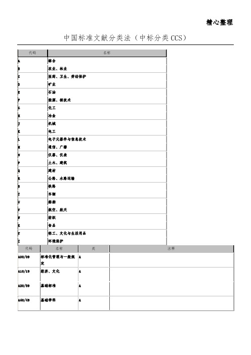
中国标准文献分类法(CCS)
无机化工原料
G
G15/19
有机化工原料
G
G20/29
化肥、农药
G
G30/39
合成材料
G
合成树脂、塑料、橡胶及胶粘剂等。建筑用塑料制品入Q22,日用塑料制品入Y28,塑料鞋入Y75或Y78。
G40/49
橡胶制品及其辅助材料
G
胶鞋入Y78。
G50/59
涂料、颜料、染料
G
G60/69
化学试剂
G
N
N60/69
实验室仪器与真空仪器
N
N70/79
试验机与无损探伤仪器
N
金属无损伤检验方法入H26。
N90/99
其他仪器仪表
N
P00/09
工程建设综合
P
P10/14
工程勘察与岩土工程
P
P15/19
工程抗震、工程防火、人防工程
P
P20/29
工程结构
P
P30/39
工业与民用建筑工程
P
P40/44
给水、排水工程
A00/09
标准化管理与一般规定
A
A10/19
经济、文化
A
A20/39
基础标准
A
A40/49
基础学科
A
A50/64
计量
A
A65/74
标准物质
A
综合性标准样品入此,专业标准样品入各专业类。
A75/79
测绘
A
A80/89
标志、包装、运输、贮存
A
A90/94
社会公共安全
A
B00/09
农业、林业综合
B
用于生产、流通过程中保证符合文字标准要求的农业、林业标样分别入本类各有关类目。
美国SOR索尔
SOR索尔差压开关17RB-EE3-N4
SOR索尔差压开关12RM-K614-M4
4NN-K4-N4-B1A
107AL-K40-P1-F1A-RR
压力开关107AL-K40-P1-FOA
压力开关101NN-K3-N4-C1A
压力开关107AL-N12-P1-F1A
54RN-K118-N4-B1A
66V1-K45-N4-B1A-
4RN-J45-N4-C2A-CL
4RN-J5-N4-C2A-CL
6RN-J3-N4-C2A-CL
4RN-J5-M9-C2A-CL
6RN-J2-N4-C2A-CL
4RN-J45-M9-C2A-CL
4B3-K45-N4-C2A-CL
6NN-K5-M4-C2A-TTXX618
12NN-K5-N4-B1A
12NN-K4-N4-C1A
12NN-K614-N4-B1A
6NN-K3-N4-F1A
101NN-EE3-M4-C1A
4NN-K4-M4-C1A-TTX2X371
101NN-EE3-N4-C1A-X373
4NN-5K-M4-CIA-X
5NN-K5-N4-F1A
5NN-K45-N4-F1A
6NN-K2-N4-F1A
6NN-K4-N4-F1A
6NN-K45-N4-F1A
9NN-K4-N4-F1A
9NN-K5-N4-F1A
9NN-K45-N4-F1A
中低压型压力开关
4NN-K2-N4-B1A
4NN-K4-N4-B1A
107EL-EG12-P1-FOA
日本白光HAKKO主机型号大全
锡线 HEXSOL FS300-01 FS400-01 FS400-02 FS401-01 FS401-02
锡线 HEXSOL FS402-01 FS402-02 FS402-03 FS402-04
化学助焊膏 PASTE(FS-120) FS120-01 FS120-02
助焊剂 001 001-01 001-02 001-03 001-04
助焊剂 CHEMICAL 1
助焊剂 SUSSOL-F 89-031 89-100 89-400 89
锡线 HEXSOL FS500-01 FS501-01 FS501-02 FS501-03 FS600-01 FS600-02 FS600-03 FS600-04
化学膏 FS-100 FS-100
焊咀清洁器 FT-700 FT700-01
电热剥线钳 FT-801 FT801-01
切割机电动装备 152B 152B
电阻切割成形机 153 153-1
电阻切割成形机 154 154-1
电阻切割机 155 155-1 155-2
精钢电子工具剪钳 106-01~08 106-01 106-02 106-03 106-04 106-05 106-06 106-07 106-08
自动出锡焊铁 958 958-01 958-02
自动出锡焊铁 959 959-01 959-02
电烙铁 FX-600 FX600-01 FX600-02
电烙铁 FX-601 FX601-01 FX601-03
定温烙铁 DASH N452 N453 N454 N452E N453E N454E
HT7039A中文资料
HT70XXVoltage DetectorSelection TablePart No.Detectable VoltageHysteresis WidthTolerance HT7022A 2.2V 0.11V ±5%HT7024A 2.4V 0.12V ±5%HT7027A 2.7V 0.135V ±5%HT7033A 3.3V 0.165V ±5%HT7039A 3.9V 0.195V ±5%HT7044A 4.4V 0.22V ±5%HT7050A 5.0V 0.25V ±5%HT7070A 7.0V0.35V±5%Note:The output type selection codes are:NMOS open drain normal open,active lowFor example:The HT7070A is a 7.0V,NMOS open drain active low outputOutput type selection tableV DDV DD >V DET (+)V DD £V DET (-)TypeV OUT AHi-ZVSSRev.1.601January 14,2003General DescriptionThe HT70XX series is a set of three-terminal low power voltage detectors implemented in CMOS technology.Each voltage detector in the series detects a particular fixed voltage ranging from 2.2V to 7V.The voltage de-tectors consist of a high-precision and low power con-sumption standard voltage source,a comparator,hysteresis circuit,and an output driver.CMOS technol-ogy ensures low power consumption.Although designed primarily as fixed voltage detectors,these devices can be used with external components to detect user specified threshold voltages (NMOS open drain type only).Features·Low power consumption ·Low temperature coefficient·Built-in high-stability reference source·Built-in hysteresis characteristic ·TO-92&SOT-89packageApplications·Battery checkers ·Level selectors ·Power failure detectors·Microcomputer reset ·Battery memory backup·Non-volatile RAM signal storage protectorsBlock DiagramN channel open drain output(normal open;active low)A typePin AssignmentRev.1.602January14,2003Pad AssignmentHT70XX (except HT7022A)Chip size:1317´1158(m m)2*The IC substrate should be connected to VDD in the PCB layout artwork.HT7022A onlyChip size:2032´1321(m m)2*The IC substrate should be connected to VDD in the PCB layout artwork.Absolute Maximum RatingsSupply Voltage,except HT7022A..................................................................................................V SS -0.3V to V SS +26V Supply Voltage,HT7022A only....................................................................................................................-0.3V to13V Output Voltage...........................V SS -0.3V to V DD +0.3V Output Current......................................................50mA Storage Temperature............................-50°C to 125°C Power Consumption..........................................200mWOperating Temperature 0°C to 70°CNote:These are stress ratings only.Stresses exceeding the range specified under ²Absolute Maximum Ratings ²maycause substantial damage to the device.Functional operation of this device at other conditions beyond those listed in the specification is not implied and prolonged exposure to extreme conditions may affect device reliabil-ity.Rev.1.603January 14,2003Pad CoordinatesHT70XX (except HT7022A)Unit:m m Pad No.X Y 1-483.30-379.502-234.60-399.503443.90-386.00HT7022A onlyUnit:m mPad No.X Y1-434.34394.972120.65461.013774.70412.75Electrical CharacteristicsHT7022A Ta=25°CHT7024A Ta=25°CHT7027A Ta=25°CRev.1.604January14,2003HT7039A Ta=25°CHT7044A Ta=25°CRev.1.605January14,2003HT7070A Ta=25°CRev.1.606January 14,2003Functional DescriptionThe HT70XX series is a set of voltage detectors equipped with a high stability voltage reference which is connected to the negative input of a comparator ¾de-noted as V REF in the following figure for NMOS output voltage detector.When the voltage drop to the positive input of the com-parator (i,e,V B )is higher than V REF ,VOUT goes high,M1turns off,and V B is expressed as V BH =V DD ´(R B +R C )/(R A +R B +R C ).If V DD is decreased so that V B falls to a value less than V REF ,the comparator output in-verts from high to low,V OUT goes low,V C is high,M1turns on,RC is bypassed,and V B becomes:V BL =V DD ´R B /(R A +R B ),which is less than V BH.By so doing,the comparator output will stay low to prevent the circuit from oscillating when V B »V REF.If V DD falls below the minimum operating voltage,the output becomes undefined.When VDD goes from low to V DD ´R B /(R A +R B )>V REF ,the comparator output and V OUT goes high.The detectable voltage is defined as:V DET (-)=R R R R R A B CB C +++´V REFThe release voltage is defined as:V DET (+)=R R R A BB+´V REFThe hysteresis width is:V HYS=V DET(+)-V DET(-)The figure demonstrates the NMOS output type withpositive output polarity(V OUT is normally open,activelow).The HT70XX series also supplies options for otheroutput types with active high outputs.Application cir-cuits shown are examples of positive output polarity(normally open,active low)unless otherwise specified.NMOS output voltage detector(HT70XXA) Application CircuitsMicrocomputer reset circuitNormally a reset circuit is required to protect the micro-computer system from malfunctions due to power line interruptions.The following examples show how differ-ent output configurations perform a reset function in var-ious systems.·NMOS open drain output application for separate power supply·NMOS open drain output application with R-C delayPower-on reset circuitWith several external components,the NMOS open drain type of the HT70XX series can be used to perform a power-on reset function as shown:Rev.1.607January14,20035V power line monitoring circuitGenerally,a minimum operating voltage of4.5V is guar-anteed in a5V power line system.The HT7044A is rec-ommended for use as5V power line monitoring circuit.·5V power line monitor with power-on reset·with5V voltage regulatorChange of detectable voltageIf the required voltage is not found in the standard prod-uct selection table,it is possible to change it by using ex-ternal resistance dividers or diodes.·Varying the detectable voltage with a resistance di-viderDetectable voltage=R RRA BB+´V DETHysteresis width=R RRA BB+´V HYS·Varying the detectable voltage with a diodeDetectable Voltage=V f1+V f2+V DETMalfunction analysisThe following circuit demonstrates the way a circuit ana-lyzes malfunctions by monitoring the variation or spikenoise of power supply voltage.Charge monitoring circuitThe following circuit shows a charged monitor for pro-tection against battery deterioration by overcharging.When the voltage of the battery is higher than the set de-tectable voltage,the transistor turns on to bypass thecharge current,protecting the battery from overcharg-ing.Rev.1.608January14,2003Level selectorThe following diagram illustrates a logic level selector.Rev.1.609January14,2003Package Information3-pin TO-92outline dimensionsSymbolDimensions in milMin.Nom.Max.A170¾200B170¾200C500¾¾D11¾20E90¾110F45¾55G45¾65H130¾160I8¾18a4°¾6°Rev.1.6010January14,20033-pin SOT-89outline dimensionsSymbolDimensions in milMin.Nom.Max.A173¾181B64¾72C90¾102D35¾47E155¾167F14¾19G17¾22H¾59¾I55¾63J14¾17Rev.1.6011January14,2003Product Tape and Reel SpecificationsTO-92reel dimensions(Unit:mm)Rev.1.6012January14,2003SOT-89reel dimensionsSOT-89Symbol Description Dimensions in mmA Reel Outer Diameter180±1.0B Reel Inner Diameter62±1.5C Spindle Hole Diameter12.75+0.15D Key Slit Width 1.9±0.15T1Space Between Flange12.4+0.2T2Reel Thickness17-0.4Rev.1.6013January14,2003TO-92Symbol Description Dimensions in mm I1Taped Lead Length(2.5)P Component Pitch12.7±1.0P0Perforation Pitch12.7±0.3P2Component to Perforation(Length Direction) 6.35±0.4F1Lead Spread 2.5+0.4-0.1F2Lead Spread 2.5+0.4-0.1D h Component Alignment0±0.1W Carrier Tape Width 18.0+1.0-0.5W0Hold-down Tape Width 6.0±0.5W1Perforation Position9.0±0.5W2Hold-down Tape Position(0.5)H0Lead Clinch Height16.0±0.5H1Component Height Less than24.7D0Perforation Diameter 4.0±0.2t Taped Lead Thickness0.7±0.2H Component Base Height19.0±0.5Note:Thickness less than0.38±0.05mm~0.5mmP0Accumulated pitch tolerance:±1mm/20pitches.()Bracketed figures are for consultation onlyRev.1.6014January14,2003SOT-89Symbol Description Dimensions in mmW Carrier Tape Width 12.0+0.3-0.1P Cavity Pitch8.0±0.1E Perforation Position 1.75±0.1F Cavity to Perforation(Width Direction) 5.5±0.05D Perforation Diameter 1.5+0.1D1Cavity Hole Diameter 1.5+0.1P0Perforation Pitch 4.0±0.1P1Cavity to Perforation(Length Direction) 2.0±0.10A0Cavity Length 4.8±0.1B0Cavity Width 4.5±0.1K0Cavity Depth 1.8±0.1t Carrier Tape Thickness0.30±0.013C Cover Tape Width9.3Rev.1.6015January14,2003Holtek Semiconductor Inc.(Headquarters)No.3,Creation Rd.II,Science-based Industrial Park,Hsinchu,TaiwanTel:886-3-563-1999Fax:886-3-563-1189Holtek Semiconductor Inc.(Sales Office)11F,No.576,Sec.7Chung Hsiao E.Rd.,Taipei,TaiwanTel:886-2-2782-9635Fax:886-2-2782-9636Fax:886-2-2782-7128(International sales hotline)Holtek Semiconductor(Shanghai)Inc.7th Floor,Building2,No.889,Yi Shan Rd.,Shanghai,ChinaTel:021-6485-5560Fax:021-6485-0313Holtek Semiconductor(Hong Kong)Ltd.RM.711,Tower2,Cheung Sha Wan Plaza,833Cheung Sha Wan Rd.,Kowloon,Hong KongTel:852-2-745-8288Fax:852-2-742-8657Holmate Semiconductor,Inc.48531Warm Springs Boulevard,Suite413,Fremont,CA94539Tel:510-252-9880Fax:510-252-9885CopyrightÓ2003by HOLTEK SEMICONDUCTOR INC.The information appearing in this Data Sheet is believed to be accurate at the time of publication.However,Holtek as-sumes no responsibility arising from the use of the specifications described.The applications mentioned herein are used solely for the purpose of illustration and Holtek makes no warranty or representation that such applications will be suitable without further modification,nor recommends the use of its products for application that may present a risk to human life due to malfunction or otherwise.Holtek reserves the right to alter its products without prior notification.For the most up-to-date information,please visit our web site at .Rev.1.6016January14,2003。
双通道时间交织ADC采样系统的频域纠正补偿
双通道时间交织ADC采样系统的频域纠正补偿黄仰超;朱锐;蒋磊;孟庆微【摘要】For the sub-channel mismatch problem in a two-channel time-interleaved analog to digital con-verter( TI-ADC) ,a frequency equalization algorithm for correcting the sub-channel mismatch is proposed. The algorithm uses the single measured coefficients on different frequencies to compensate the frequency re-sponse and its feasibility is verified theoretically and experimentally. Experiment results indicate that,in a two-channel 12 bit 2 Gsample/s TI-ADC system adopting the algorithm,the measured spurious free dy-namic range( SFDR) can be improved to 40 dB when the input signal is limited to 650 MHz.%针对双通道时间交织模数转换器( ADC )采样系统中的通道间失配问题,提出了一种新的频域纠正补偿算法,即利用单次测量得到的不同频率处的固定补偿系数来实现时间交织ADC频响的部分补偿,并从理论和实验上分别进行了推导和可行性验证。
实验结果表明:在双通道12比特2 Gsample/s时间交织ADC采样系统下,650 MHz带宽范围内的无杂散动态范围( SFDR)可以提高到40 dB。
- 1、下载文档前请自行甄别文档内容的完整性,平台不提供额外的编辑、内容补充、找答案等附加服务。
- 2、"仅部分预览"的文档,不可在线预览部分如存在完整性等问题,可反馈申请退款(可完整预览的文档不适用该条件!)。
- 3、如文档侵犯您的权益,请联系客服反馈,我们会尽快为您处理(人工客服工作时间:9:00-18:30)。
安捷伦模块化8通道相参宽带接收机系统安捷伦科技(中国)有限公司一、设备名称: M9703A & M9362A 多通道相参宽带接收机系统二、产品型号及组成:M9036A PXI嵌入式控制器、M9018A PXI机箱、M9302A本振、M9168C程控步进衰减器(可选)、M9362A-D01宽带下变频器、M9352A中频信号调理模块、N5181A MXG 模拟信号发生器(可选,用于10MHz~2.25GHz频段时钟)、M9703A高速数字化仪、VSA 89601B 矢量信号分析软件。
三、方案配置及说明1、硬件组成及实现系统基于PXI及AXIe平台构建,PXI部分用于对信号的下变频处理及中频信号调理,AXIe部分用于中频信号的数字化,板载FPGA内建DDC算法,整个系统可实现2.25GHz~26.5GHz频率范围下780MHz/ch分析带宽,通过可选的N5181A MXG提供混频器参考时钟,最终可实现10MHz~26.5GHz 频率范围下780MHz/ch分析带宽。
并且,通过推荐的安捷伦VSA 89601B矢量信号分析软件,无需进行程序开发,即可针对70余种标准调制信号进行解调分析,20:20 迹线/游标功能,可提供更全面的分析,通过多域数字余辉和积累的历史迹线捕捉短暂信号,VSA 可对设计结构图中的任何位置进行分析,分析模拟和数字基带,中频、射频和微波,窄带至超宽带、SISO和MIMO。
M9032A本振模块为M9362A-D01四通道下变频器模块提供2.75GHz~26.5GHz时钟(通过功分器连接至LO In),并为M9703A多通道高速数字化仪提供100MHz Reference,2.25GHz以下的时钟信号则由N5181A MXG提供。
图例,N5181A MXGM9703A & M9362A 多通道相参宽带接收机系统图示2、软件结构1)、驱动程序:安捷伦模块化仪器提供 IVI-COM、IVI-C、LabVIEW和 MATLAB 软件驱动程序,这些程序可在诸如VisualStudio(、C#、C/C++)、VEE、LabVIEW 和 LabWindows/CVI 和 MATLAB 等常用测试测量开发环境中运行。
该仪器驱动程序提供了上下关联的帮助功能以及全套文档和示例,使您可以快速入门,完成复杂的测试任务。
软件前面板:快速配置,实施应用。
LabVIEW VIs,快速创建测试测量应用2)、应用软件:VSA 89601B(推荐)支持在线及离线分析安捷伦业界领先的矢量信号分析软件(VSA)帮助您轻松掌握业内的新兴标准和现有标准。
VSA 软件可以帮助您洞悉复杂的信号交互,它支持:1、测量 70 多种信号标准和调制类型✓ 2 至 16FSK、BPSK、QPSK、16 至 1024QAM、Star QAM、高达 64APSK、AM/FM/PM、定制 APSK✓LTE-Advanced FDD/TDD、W-CDMA/HSPA+、GSM/Edge Evolution 和其它移动通信标准✓802.11ac、802.11n、WiMAX™、RFID、Zigbee 和其它无线连通性标准✓定制 OFDM:分析专有或准标准信号2、利用相应的 20:20 曲线/光标功能以提高测量清晰度✓利用任意安排迹线(高达 20 条测量迹线)和对迹线进行自由缩放的能力精确确定问题✓调整迹线形状以延长事件观察时间或增加可视数据✓优化迹线安排以观察信号码型和研究交互✓对任何迹线指定任意测量以分析复杂信号,例如 4x4 MIMO✓通过每条迹线的 20 个游标和迹线到迹线耦合,隔离多余的交互源3、多域数字余辉和积累的历史迹线捕获短暂信号✓利用数字余辉分析重复的猝发脉冲和瞬时信号✓捕获偶发或随机信号事件,并通过累积的历史记录执行详细分析✓在时域、频域和调制域使用4、可对设计结构图中的任何位置进行分析✓分析模拟和数字基带,中频、射频和微波,窄带至超宽带、SISO和MIMO✓支持超过30个测量平台四、技术指标1.M9036A PXI嵌入式控制器✓Intel Core i5-520E 2.4GHz 处理器。
✓160 GB 固态硬盘。
✓ 4 GB RAM 内存,支持最大8GB扩展。
✓2代PCIe®, 提供最大4 GB/s 数据带宽。
✓前面板接口包括USB (4), 10/100/1000 以太网接口 (2), DVI-I, GPIB, ExpressCard 34以及 SMB 触发连接器接口。
✓支持微软Windows® 7 (32 and 64 bit)操作系统。
2.M9018A PXI机箱✓16 个PXIe 混合插槽, 1个 PXIe 定时插槽,以及 1个 PXIe 系统插槽。
✓4U 机箱,创新的制冷设计。
✓高数据带宽(系统插槽与扩展插槽之间最大8GB/s,扩展插槽之间最大4GB/s)。
✓先进的2代 PCIe 背板总线技术,支持4个 x8 链路以及12个 x4 链路的混合插槽。
✓可配置的PXIe 系统插槽。
3.M9302A本振✓频率范围:2.75GHz~10GHz✓0.1Hz 调谐分辨率✓1ms 稳定时间✓相位噪声:-115 dBc/Hz at 10 GHz, 10 kHz offset4.M9168C程控步进衰减器(可选)✓频率:直流至26.5GHz✓0 到 101 dB 的宽衰减范围 ,以 1 dB 步进✓衰减分辨率:1 dB、5 dB 和 10 dB 步进✓可重复性保证 0.03 dB✓寿命周期至少 500 万次✓最大输入功率1 W (+30 dBm) 平均值 , 50 W 峰值(10 μs 最大值 ) ✓最大反向功率1 W 平均值 , 50 W 峰值(10 μs 最大值 )✓射频连接器兼容 3.5 mm ( 母头 ) SMA5.M9362A-D01宽带下变频器✓频率范围:10MHz~26.5GHz ✓ 1.5GHz带宽✓四通道同步下变频6.M9352A中频信号调理模块✓频率范围:10MHz~1GHz✓通道数量:4✓衰减范围:31.5dB以0.5dB步进✓中频增益:最大35dB✓噪声系数:3dB✓输入TOI:+43dB7.M9703A 多通道高速数字化仪✓8 通道同步 ( 交织采样模式为 4 通道 )✓ 12 位分辨率✓每通道 1 GS/s ( 可选 1.6 GS/s) 采样率✓ 650 MHz ( 可选 1 GHz) 带宽✓交织采样模式可以 2 GS/s ( 可选 3.2 GS/s) 采样率进行 4 通道采样✓可选择 1 V/2 V 满量程 (FSR)✓ ± FSR 输入电压偏置范围✓50 Ω 输入阻抗✓精确的触发时间 (time-to-trigger) 内插器✓板上存储器高达 4 GB (256 MSa/ 通道 )✓ 4 通道 (x4) PCIe Gen 2 背板链路五、系统特性PXIe 总线PXI Express仪器采用PCIe总线技术,为PXI平台新添了许多技术优势。
该总线至多个仪器系统的数据吞吐量可以高达4 GB/s,从而可用于那些曾经只能通过定制硬件才可能实现的应用。
由于PXI新的标准采用了PCIe技术,PXI自动化测试系统提供了前所未有的高性能。
在有些情况下,PXI仪器现在可以执行一些迄今一直无法完成的测量。
PXI Express是由PXI扩展所得。
新型PXI Express机箱提供了支持PXI与PXI Express模块协同工作于同一系统的混合兼容的插槽。
利用软件定义方式实现仪器系统的灵活性,您可以为各种测量应用重新配置测试系统。
而通过将模块化仪器集成到同一个系统,您可以从超过1500种现有PXI仪器中选择合适的仪器。
您可以利用PXI Express仪器的高数据吞吐量的特性,创建若干项新型应用。
凭借总线的高吞吐量,您可以在高速数据流导入磁盘或数据流导出磁盘配置应用中,协同使用PXI Express仪器与PXI Express RAID硬盘驱动器。
PXI Express仪器系统的最大技术优势在于PCIe总线的高数据吞吐量。
这一优势不仅缩短了常见自动化测试应用的测试时间,也使得使用现有商用硬件无法实现的新型应用得以实现。
传统的台式仪器,如任意波形发生器、逻辑分析仪和示波器等,使用板上有限的存储器作为存储波形数据的临时缓存。
板上存储器昂贵而且可用空间有限。
然后,这些仪器系统可以通过GPIB、LAN或USB接口将波形输入至PC或自PC输出波形。
糟糕的是,这样的数据吞吐量仅仅是数兆字节每秒。
对于数据流导入磁盘或数据流导入内存等应用,需要高得多的吞吐量。
PXI Express凭借其高吞吐量和低总线时延,提供了一个引人瞩目的解决方案。
系统的物理特性PXI是一个模块化的平台。
系统的物理主机是一个拥有18个槽位(更有多种槽位可供选择以适合不同用户的需要)的机箱。
机箱的第一槽(Slot 1)是控制器槽。
嵌入式控制器是专为PXI机箱空间设计的具有工业级特性的计算机。
机箱中的其它槽位被称为外部设备槽,用于插置功能模块,就像计算机里的PCI槽一样。
PXI 提供了在所有情况下可以达到的的最佳电气性能。
这些已经被广泛采纳于各种高性能的应用,尤其是航空航天,军事和通信领域。
在尺寸上,本系统的4U 的PXI 机箱比绝大多数的台式或工业计算机平台更加紧凑。
机箱的设计考虑了系统集成的需要,使之能够很方便地固定到机柜上。
最后,PXI 模块化、前插式的结构给维护和升级带来的极大的便利。
如果系统中的一个模块需要修理,工程师可以将其取出,而不影响其它任何模块。
模块化减少的的停机时间降低了系统寿命内的维护成本。
系统的机械特性PXI 机箱和设备是为承受工业和野外环境而设计的,模块也都具有牢固的接插端,可以抵抗撞击与振动。
为了保护电路,机箱内设计有额外的冷却装置。
此外,设备都是从机箱的前面拆卸,维护与升级非常方便。
PXI 规范要求所有的设备都通过环境测试。
厂家进行湿度、撞击和振动测试。
PXI 机箱通常在背板上只有很少的电路,这样当任何电路需要更换的时候,维护都非常简单。
PXI 规范对冷却具有严格的要求。
PXI 带有强迫冷却装置,产生特定方向的气流,均匀冷却所有模块。
均衡的冷却可以延长模块或板卡的使用寿命,从而降低系统寿命内的平均维护成本。
最后,所有的PXI设备都经过测试,清楚标明工作和存放时的正常温度。
由于PXI系统的模块化,升级单个组件很容易。
比方说,某用户希望升级到更快的处理器,他可以拆下控制器进行更换。
因为所有的设备都支持标准软件,所以只要在新的控制器里装上软件和驱动程序,然后插回机箱内就可以了。
系统的电气特性PXI 的背板提供了一些专为测试和测量工程设计的独到特性。
专用的系统时钟用于模块间的同步;8条独立的触发线可以精确同步两个或多个模块;槽与槽之间的局部总线可以节省PCI 总线的带宽;最后,可选用的星形触发特性适用于极高精度的触发。
