1SS272中文资料
贴片元件标记对应型号资料
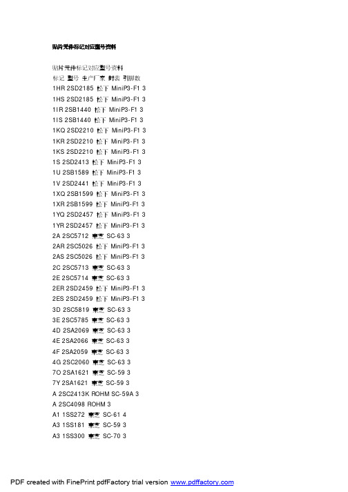
贴片元件标记对应型号资料贴片元件标记对应型号资料标记型号生产厂家封装引脚数1HR 2SD2185 松下MiniP3-F1 3 1HS 2SD2185 松下MiniP3-F1 3 1IR 2SB1440 松下MiniP3-F1 3 1IS 2SB1440 松下MiniP3-F1 3 1KQ 2SD2210 松下MiniP3-F1 3 1KR 2SD2210 松下MiniP3-F1 3 1KS 2SD2210 松下MiniP3-F1 3 1S 2SD2413 松下MiniP3-F1 3 1U 2SB1589 松下MiniP3-F1 3 1V 2SD2441 松下MiniP3-F1 3 1XQ 2SB1599 松下MiniP3-F1 3 1XR 2SB1599 松下MiniP3-F1 3 1YQ 2SD2457 松下MiniP3-F1 3 1YR 2SD2457 松下MiniP3-F1 3 2A 2SC5712 東芝SC-63 32AR 2SC5026 松下MiniP3-F1 3 2AS 2SC5026 松下MiniP3-F1 3 2C 2SC5713 東芝SC-63 32E 2SC5714 東芝SC-63 32ER 2SD2459 松下MiniP3-F1 3 2ES 2SD2459 松下MiniP3-F1 3 3D 2SC5819 東芝SC-63 33E 2SC5785 東芝SC-63 34D 2SA2069 東芝SC-63 34E 2SA2066 東芝SC-63 34F 2SA2059 東芝SC-63 34G 2SC2060 東芝SC-63 37O 2SA1621 東芝SC-59 37Y 2SA1621 東芝SC-59 3A 2SC2413K ROHM SC-59A 3 A 2SC4098 ROHM 3A1 1SS272 東芝SC-61 4A3 1SS181 東芝SC-59 3A3 1SS300 東芝SC-70 3A4 1SS319 東芝SC-61 4A4 1SS383 東芝4A5 1SS384 東芝SOT-343 4A5 1SS391 東芝SC-61 4A6 HN2S01F 東芝SC-74 6A6 HN2S01FU 東芝SC-88 6 A7 1SS402 東芝SOT-343 4A9 1SS294 東芝SC-59 3AL 2SA1971 東芝SC-63 3AL 2SC5307 東芝SC-63 3AN 2SC2532 東芝SC-59 3 AO 2SA2880 東芝SC-63 3 AQ 2SB766 松下MiniP3-F1 3 AR 2SB766 松下MiniP3-F1 3 AS 2SB766 松下MiniP3-F1 3 AU 2SB804 NEC SC-62 3AV 2SB804 NEC SC-62 3AW 2SB804 NEC SC-62 3AY 2SA2880 東芝SC-63 3B 2CS4081 ROHM 3B 2SC2412K ROHM SC-59A 3 B3 1SS184 東芝SC-59 3B3 1SS301 東芝SC-70 3B9 1SS311 東芝SC-59 3B9 1SS397 東芝SC-70 3BD 1SS271 東芝SC-59 3BE 1SV172 東芝BF 1SS268 東芝SC-59 3BG 1SS269 東芝SC-59 3BH 1SS295 東芝SC-59 3BO 2SA1200 東芝SC-63 3 BQ 2SB766A 松下MiniP3-F1 3 BR 2SB766A 松下MiniP3-F1 3 BS 2SB766A 松下MiniP3-F1 3 BU 2SD1005 NEC SC-62 3BU DA228K ROHM SC-59 3 BU DA228U ROHM SC-70 3 BV 2SD1005 NEC SC-62 3BW 2SD1005 NEC SC-62 3BY 2SA1200 東芝SC-63 3C 2SC2411K ROHM SC-59A 3C 2SC4097 ROHM 3C1 1SS352 東芝C1 1SS387 東芝C3 1SS226 東芝SC-59 3C9 1SS307 東芝SC-59 3CEO 2SC3325 東芝SC-59 3 CEY 2SC3325 東芝SC-59 3CG 2SA1163 東芝SC-59 3CK 2SD999 NEC SC-62 3CL 2SD999 NEC SC-62 3CM 2SD999 NEC SC-62 3CO 2SC2881 東芝SC-63 3CO 2SC4209 東芝SC-59 3CQ 2SB767 松下MiniP3-F1 3 CR 2SB767 松下MiniP3-F1 3 CY 2SC2881 東芝SC-63 3CY 2SC4209 東芝SC-59 3D 2SA1037KLN ROHM SC-59A 3 D3 1SS187 東芝SC-59 3DG 2SC2713 東芝SC-59 3DK 2SB798 NEC SC-62 3DL 2SB798 NEC SC-62 3DM 2SB798 NEC SC-62 3DO 2SA1201 東芝SC-63 3DQ 2SB789 松下MiniP3-F1 3 DR 2SB789 松下MiniP3-F1 3 DY 2SA1201 東芝SC-63 3E3 1SS190 東芝SC-59 3EK 2SD1001 NEC SC-62 3EL 2SD1001 NEC SC-62 3EM 2SD1001 NEC SC-62 3EO 2SC2882 東芝SC-63 3EQ 2SB789A 松下MiniP3-F1 3 ER 2SB789A 松下MiniP3-F1 3 EX 2SD2402 NEC SC-62 3EY 2SC2882 東芝SC-63 3EY 2SD2402 NEC SC-62 3EZ 2SD2402 NEC SC-62 3F 2SA1037K ROHM SC-59A 3 F 2SA1576 ROHM 3F3 1SS193 東芝SC-59 3F5 1SS250 東芝SC-59 3F5 1SS370 東芝SC-70 3F5 1SS403 東芝SOD-323 2F9 1SS321 東芝SC-59 3FK 2SB800 NEC SC-62 3FL 2SB800 NEC SC-62 3FM 2SB800 NEC SC-62 3FO 2SA1202 東芝SC-63 3FX 2SB1571 NEC SC-62 3FY 2SA1202 東芝SC-63 3FY 2SB1571 NEC SC-62 3FZ 2SB1571 NEC SC-62 3G3 1SS196 東芝SC-59 3G3 2SA1455K ROHM SC-59A 3 GK 2SD1615 NEC SC-62 3GL 2SD1615 NEC SC-62 3GM 2SD1615 NEC SC-62 3 GO 2SC2883 東芝SC-63 3 GP 2SD1615A NEC SC-62 3 GQ 2SD1615A NEC SC-62 3 GX 2SD2403 NEC SC-62 3GY 2SC2883 東芝SC-63 3GY 2SD2403 NEC SC-62 3GZ 2SD2403 NEC SC-62 3H9 1SS344 東芝SC-59 3HK 2SD1006 NEC SC-62 3HL 2SD1006 NEC SC-62 3HM 2SD1006 NEC SC-62 3 HO 2SA1203 東芝SC-63 3HP 2SD1007 NEC SC-62 3HQ 2SD1007 NEC SC-62 3HR 2SD1007 NEC SC-62 3HR 2SB956 松下MiniP3-F1 3 HS 2SB956 松下MiniP3-F1 3 HX 2SB1572 NEC SC-62 3HY 2SA1203 東芝SC-63 3HY 2SB1572 NEC SC-62 3HZ 2SB1572 NEC SC-62 3I9 1SS336 東芝SC-59 3IK 2SA1463 NEC SC-62 3IL 2SA1463 NEC SC-62 3IO 2SC3515 東芝SC-63 3IQ 2SB1073 松下MiniP3-F1 3 IR 2SC3515 東芝SC-63 3IR 2SB1073 松下MiniP3-F1 3 J 2SC2059K ROHM SC-59A 3J 2SC4099 ROHM 3J9 1SS337 東芝SC-59 3JO 2SA1384 東芝SC-63 3JR 2SK208 東芝SC-59 3JR 2SA1384 東芝SC-63 3K DA221 ROHM SC-75A 3K DA204U ROHM SC-70 3K DA204K ROHM SC-59 3K9 1SS348 東芝SC-59 3KA 2SC4409 東芝SC-63 3KD 2SC4541 東芝SC-63 3KK 2SB805 NEC SC-62 3KL 2SB805 NEC SC-62 3KM 2SB805 NEC SC-62 3KP 2SB806 NEC SC-62 3KQ 2SB806 NEC SC-62 3KR 2SB806 NEC SC-62 3L 2SC2412KLN ROHM SC-59A 3 L9 1SS349 東芝SC-59 3LA 2SA1681 東芝SC-63 3LD 2SA1736 東芝SC-63 3LK 2SD1000 NEC SC-62 3LL 2SD1000 NEC SC-62 3LM 2SD1000 NEC SC-62 3MK 2SB799 NEC SC-62 3 ML 2SB799 NEC SC-62 3 MM 2SB799 NEC SC-62 3 MO 2SC2873 東芝SC-63 3 MY 2SC2873 東芝SC-63 3 N9 1SS372 東芝SC-70 3 N9 1SS374 東芝SC-59 3 NA 2SK1273 NEC SC-62 3 NB 2SK1586 NEC SC-62 3 NC 2SK1485 NEC SC-62 3 ND 2SK1583 NEC SC-62 3 NE 2SK1585 NEC SC-62 3 NF 2SK1587 NEC SC-62 3 NG 2SK1588 NEC SC-62 3 NH 2SK1584 NEC SC-62 3 NI 2SK1586 NEC SC-62 3 NJ 2SK2111 NEC SC-62 3 NK 2SC2780 NEC SC-62 3 NL 2SC2780 NEC SC-62 3 NM 2SC2780 NEC SC-62 3 NO 2SA1213 東芝SC-63 3 NO 2SK1592 NEC SC-62 3 NP 2SK1593 NEC SC-62 3 NQ 2SK1959 NEC SC-62 3 NR 2SK1960 NEC SC-62 3 NS 2SK2109 NEC SC-62 3 NT 2SK2110 NEC SC-62 3 NV 2SK2112 NEC SC-62 3 NW 2SK2159 NEC SC-62 3 NX 2SK2857 NEC SC-62 3 NY 2SA1213 東芝SC-63 3 O9 1SS377 東芝SC-59 3 O9 1SS378 東芝SC-70 3 O9 1SS385 東芝SC-75 3 O9 1SS385F 東芝SC-81 3 OK 2SC3736 NEC SC-62 3 OL 2SC3736 NEC SC-62 3PA 2SJ179 NEC SC-62 3PB 2SJ197 NEC SC-62 3PC 2SJ199 NEC SC-62 3PD 2SJ205 NEC SC-62 3PE 2SJ207 NEC SC-62 3PF 2SJ208 NEC SC-62 3PH 2SJ206 NEC SC-62 3PO 2SC2884 東芝SC-63 3 PO 2SJ212 NEC SC-62 3PP 2SJ213 NEC SC-62 3PQ 2SJ355 NEC SC-62 3PR 2SJ356 NEC SC-62 3PY 2SC2884 東芝SC-63 3 QO 2SC2714 東芝3R12 UMR12N ROHM SC-88 6 R23 2SC3356 Q NEC SC-59 3 R24 2SC3356 R NEC SC-59 3 R25 2SC3356 S NEC SC-59 3 R9 1SS392 東芝SC-59 3R9 1SS393 東芝SC-70 3RQ 2SD1280 松下MiniP3-F1 3 RR 2SD1280 松下MiniP3-F1 3 RS 2SD1280 松下MiniP3-F1 3 S2 1SS315 東芝SC-59 3S9 1SS394 東芝SC-59 3SA 2SC2982 東芝SC-63 3SK 2SC3554 NEC SC-62 3SL 2SC3554 NEC SC-62 3SM 2SC3554 NEC SC-62 3 SO 2SA1162 東芝SC-59 3T9 1SS396 東芝SC-59 3TA 2SA1314 東芝SC-63 3TA 1SV231 東芝1-1E1A 2TB 2SA1314 東芝SC-63 3TC 2SA1314 東芝SC-63 3TE 2SD1702 NEC SC-62 3TF 2SD1702 NEC SC-62 3TL 2SC3617 NEC SC-62 3TM 2SC3617 NEC SC-62 3TQ 2SD1699 NEC SC-62 3TQ 2SD1119 松下MiniP3-F1 3 TR 2SD1699 NEC SC-62 3TR 2SD1119 松下MiniP3-F1 3 UK 2SC3618 NEC SC-62 3UL 2SC3618 NEC SC-62 3UM 2SC3618 NEC SC-62 3VK 2SD1950 NEC SC-62 3VL 2SD1950 NEC SC-62 3VM 2SD1950 NEC SC-62 3 VR 2SD968A 松下MiniP3-F1 3 VS 2SD968A 松下MiniP3-F1 3 VY 2SJ106 東芝SC-59 3W 2SD1383K ROHM SC-59A 3 W3 FMW3 ROHM 5X9 1SS398 東芝SC-59 3XK 2SD1614 NEC SC-62 3XL 2SD1614 NEC SC-62 3XM 2SD1614 NEC SC-62 3 XN 2SD1784 東芝SC-63 3 XR 2SD875 松下MiniP3-F1 3 XS 2SD875 松下MiniP3-F1 3 YB 2SK680A NEC SC-62 3YK 2SB1115 NEC SC-62 3YL 2SB1115 NEC SC-62 3YM 2SB1115 NEC SC-62 3YP 2SB1115A NEC SC-62 3 YQ 2SB1115A NEC SC-62 3 YQ 2SD874A 松下MiniP3-F1 3 YR 2SD874A 松下MiniP3-F1 3 YS 2SD874A 松下MiniP3-F1 3 Z7 2SK2549 東芝SC-63 3Z8 2SJ360 東芝SC-63 3Z9 2SJ465 東芝SC-63 3ZA 2SK2615 東芝SC-63 3ZB 2SK2963 東芝SC-63 3 ZC 2SK2964 東芝SC-63 3 ZD 2SK2992 東芝SC-63 3 ZE 2SJ508 東芝SC-63 3ZF 2SJ511 東芝SC-63 3ZG 2SK3471 東芝SC-63 3 ZK 2SB1114 NEC SC-62 3 ZL 2SB1114 NEC SC-62 3 ZM 2SB1114 NEC SC-62 3 ZO 2SA1182 東芝SC-59 3 ZQ 2SD874 松下MiniP3-F1 3 ZR 2SD874 松下MiniP3-F1 3 ZS 2SD874 松下MiniP3-F1 3 ZX 2SB1628 NEC SC-62 3 ZY 2SB1628 NEC SC-62 3 ZZ 2SB1628 NEC SC-62 3。
KAQW210S中文资料
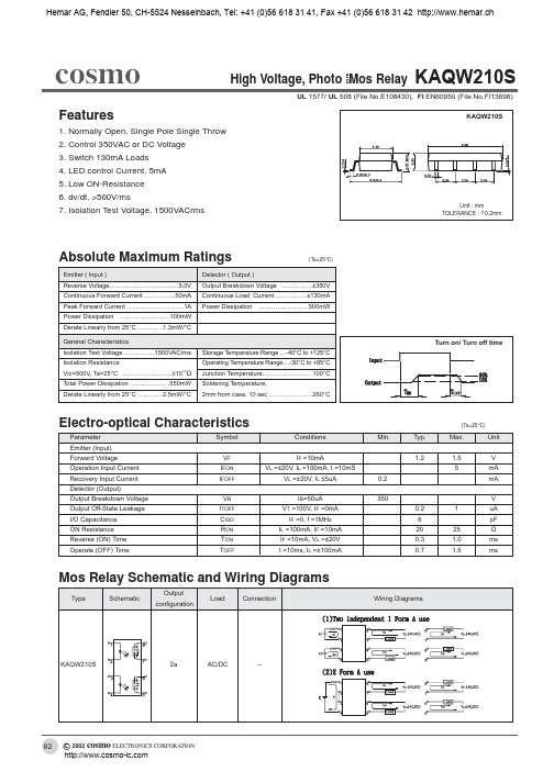
Fig.8 Voltage vs. current characteristics of output at MOS FET portion Measured portion: across terminals 5,7 and 6,8 pin Ambient temperature: 25°C
Fig.9 Off state leakage current Across terminals 5,7 and 6,8 pin Ambient temperature: 25°C
(Ta=25°C)
Max.
Unit V mA mA V uA pF Ω ms ms
Mos Relay Schematic and Wiring Diagrams
Type Schematic Output configuration Load Connection Wiring Diagrams
KAQW210S
2a
AC/DC
–
92
c 2002 cosmo ELECTRONICS CORPORATION
Hemar AG, Fendler 50, CH-5524 元器件交易网 Nesselnbach, Tel: +41 (0)56 618 31 41, Fax +41 (0)56 618 31 42
LED Operate Current (mA)
Ambient Temperature Ta (°C)
Ambient Temperature Ta (°C)
LED Turn off Current (mA)
Tun off Time Msec
Ambient Temperature Ta (°C)
Fig.7 LED dropout voltage vs. ambient temperature LED current: 5 to 50mA
2732资料

● The ferrite core is a slim EE50-type, leading to a maximum transformer height of 28mm above the PCB
38.1
18.5 25 20 15 15 16.25 16.25 15 20 16.25 20.32 20.32 27
Pitch Power Input (mm) @ 50 kHz (W)
7.5
30
5
40
4
40
5
40
5
40
5
60
5
90
5
190
5
250
5
130
4
40
4
40
5
60
5
90
5
120
5
200
5
● Maximum horizontal dimensions: 51mm x 52mm
Options
● Customized electrical design and pinout
SLOT SMT 100
Series 2642 – Resonant-Type Power Supply Switch-Mode Transformer
SWITCH-MODE TRANSFORMER GUIDE BY TECHNOLOGY
Ferrite
E30/15/7 ETD29X16X10 ETD29X15X10 ETD29X11X10 ETD34X13X11 ETD34X17X11 ETD39X17X13 ER48X18X18 ER54X20X18
1SS82资料
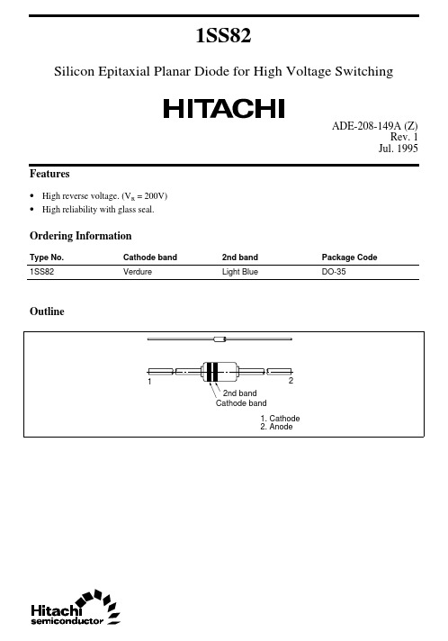
1SS82Silicon Epitaxial Planar Diode for High Voltage SwitchingADE-208-149A (Z)Rev. 1Jul. 1995 Features• High reverse voltage. (V R = 200V)• High reliability with glass seal.Ordering InformationType No.Cathode band2nd band Package Code1SS82Verdure Light Blue DO-35Outline1SS822Absolute Maximum Ratings *2 (Ta = 25°C)ItemSymbol Value Unit Peak reverse voltage V RM *1250V Reverse voltage V R 200V Peak forward currentI FM 625mA Non-Repetitive peak forward surge current I FSM *21A Average forward current I O 200mA Power dissipation Pd 400mW Junction temperature Tj 175°C Storage temperatureTstg–65 to +175°CNotes: 1.Reverse voltage in excess of peak reverse voltage may deteriorate electrical characteristic.2.Within 1s forward surge current.Electrical Characteristics (Ta = 25°C)ItemSymbol Min Typ Max Unit Test Condition Forward voltage V F —— 1.0V I F = 100mA Reverse current I R1——0.2µAV R = 200V I R2——100V R = 250V CapacitanceC — 1.5—pF V R = 0V, f = 1MHzReverse recovery timet rr——100ns I F = I R = 30mA, Irr = 3mA, R L = 100Ω1SS82Fig.1 Forward current Vs. Forward voltageFig.2 Reverse current Vs. Reverse voltage31SS82Fig.3 Capacitance Vs. Reverse voltage 41SS82 Package Dimensions5Cautions1.Hitachi neither warrants nor grants licenses of any rights of Hitachi’s or any third party’s patent,copyright, trademark, or other intellectual property rights for information contained in this document.Hitachi bears no responsibility for problems that may arise with third party’s rights, includingintellectual property rights, in connection with use of the information contained in this document.2.Products and product specifications may be subject to change without notice. Confirm that you have received the latest product standards or specifications before final design, purchase or use.3.Hitachi makes every attempt to ensure that its products are of high quality and reliability. However,contact Hitachi’s sales office before using the product in an application that demands especially high quality and reliability or where its failure or malfunction may directly threaten human life or cause risk of bodily injury, such as aerospace, aeronautics, nuclear power, combustion control, transportation,traffic, safety equipment or medical equipment for life support.4.Design your application so that the product is used within the ranges guaranteed by Hitachi particularly for maximum rating, operating supply voltage range, heat radiation characteristics, installationconditions and other characteristics. Hitachi bears no responsibility for failure or damage when used beyond the guaranteed ranges. Even within the guaranteed ranges, consider normally foreseeable failure rates or failure modes in semiconductor devices and employ systemic measures such as fail-safes, so that the equipment incorporating Hitachi product does not cause bodily injury, fire or other consequential damage due to operation of the Hitachi product.5.This product is not designed to be radiation resistant.6.No one is permitted to reproduce or duplicate, in any form, the whole or part of this document without written approval from Hitachi.7.Contact Hitachi’s sales office for any questions regarding this document or Hitachi semiconductor products.Hitachi, Ltd.Semiconductor & Integrated Circuits.Nippon Bldg., 2-6-2, Ohte-machi, Chiyoda-ku, Tokyo 100-0004, Japan Tel: Tokyo (03) 3270-2111 Fax: (03) 3270-5109Copyright ' Hitachi, Ltd., 1999. All rights reserved. Printed in Japan.Hitachi Asia Pte. Ltd.16 Collyer Quay #20-00Hitachi TowerSingapore 049318Tel: 535-2100Fax: 535-1533URLNorthAmerica : http:/Europe : /hel/ecg Asia (Singapore): .sg/grp3/sicd/index.htm Asia (Taiwan): /E/Product/SICD_Frame.htm Asia (HongKong): /eng/bo/grp3/index.htm Japan : http://www.hitachi.co.jp/Sicd/indx.htmHitachi Asia Ltd.Taipei Branch Office3F, Hung Kuo Building. No.167, Tun-Hwa North Road, Taipei (105)Tel: <886> (2) 2718-3666Fax: <886> (2) 2718-8180Hitachi Asia (Hong Kong) Ltd.Group III (Electronic Components)7/F., North Tower, World Finance Centre,Harbour City, Canton Road, Tsim Sha Tsui,Kowloon, Hong Kong Tel: <852> (2) 735 9218Fax: <852> (2) 730 0281 Telex: 40815 HITEC HXHitachi Europe Ltd.Electronic Components Group.Whitebrook ParkLower Cookham Road MaidenheadBerkshire SL6 8YA, United Kingdom Tel: <44> (1628) 585000Fax: <44> (1628) 778322Hitachi Europe GmbHElectronic components Group Dornacher Stra§e 3D-85622 Feldkirchen, Munich GermanyTel: <49> (89) 9 9180-0Fax: <49> (89) 9 29 30 00Hitachi Semiconductor (America) Inc.179 East Tasman Drive,San Jose,CA 95134 Tel: <1> (408) 433-1990Fax: <1>(408) 433-0223For further information write to:。
S1132_中文规格书
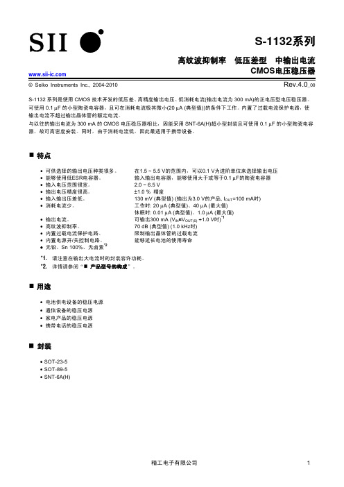
精工电子有限公司
5
高纹波抑制率 S-1132系列
低压差型
中输出电流CMOS电压稳压器 Rev.4.0_00
绝对最大额定值
表5 项目 输入电压 输出电压 SOT-23-5 容许功耗 SOT-89-5 SNT-6A(H) 工作环境温度 保存温度 *1. 基板安装时 [安装基板] (1) 基板尺寸: (2) 名称: Topr Tstg PD 符号 VIN VON/OFF VOUT (除特殊注明以外: Ta=25°C) 绝对最大额定值 单位 V VSS−0.3 ∼ VSS+7 V VSS−0.3 ∼ VIN+0.3 V VSS−0.3 ∼ VIN+0.3 300(基板未安装时) mW 600*1 500(基板未安装时) 1000*1 500
*1. 请注意在输出大电流时的封装容许功耗。 *2. 详情请参阅“ 产品型号的构成”。
用途
• 电池供电设备的稳压电源 • 通信设备的稳压电源 • 家电产品的稳压电源 • 携带电话的稳压电源
封装
• SOT-23-5 • SOT-89-5 • SNT-6A(H)
精工电子有限公司
1
高纹波抑制率 S-1132系列 框图
S-1132
x
xx
−
xxxx
x
环保标记 U: 无铅 (Sn 100%)、无卤素 G: 无铅 (详情请向本公司营业部咨询) 封装简称和IC的包装规格*1 M5T1: SOT-23-5、卷带产品 U5T1: SOT-89-5、卷带产品 I6T2: SNT-6A(H)、卷带产品 输出电压 12 ~ 55 (例: 当输出电压为1.5 V时,表示为15) 产品类型*2 A: ON/OFF端子为负逻辑型 B: ON/OFF端子为正逻辑型 *1. *2. 请参阅卷带图。 请参阅工作说明“3. 开/关控制端子(ON/OFF 端子)”。
pt2262_pt2272中文资料

PT2262/PT2272编码解码芯片中文资料PT2262/PT2272是台湾普城公司生产的一种CMOS工艺制造的低功耗低价位通用编解码电路,PT2262/PT2272最多可有12位(A0-A11)三态地址端管脚(悬空,接高电平,接低电平),任意组合可提供531441地址码,PT2262最多可有6位(D0-D5)数据端管脚,设定的地址码和数据码从17脚串行输出,可用于无线遥控发射电路。
编码芯片PT2262发出的编码信号由:地址码、数据码、同步码组成一个完整的码字,解码芯片PT2272接收到信号后,其地址码经过两次比较核对后,VT脚才输出高电平,与此同时相应的数据脚也输出高电平,如果发送端一直按住按键,编码芯片也会连续发射。
当发射机没有按键按下时,PT2262不接通电源,其17脚为低电平,所以315MHz的高频发射电路不工作,当有按键按下时,PT2262得电工作,其第17脚输出经调制的串行数据信号,当17脚为高电平期间315MHz的高频发射电路起振并发射等幅高频信号,当17脚为低平期间3 15MHz的高频发射电路停止振荡,所以高频发射电路完全收控于PT2262的17脚输出的数字信号,从而对高频电路完成幅度键控(ASK调制)相当于调制度为100%的调幅。
PT2262/PT2272特点l CMOS工艺制造,低功耗l 外部元器件少l RC振荡电阻l 工作电压范围宽:2.6-15vl 数据最多可达6位l 地址码最多可达531441种PT2262/PT2272应用范围l 车辆防盗系统l 家庭防盗系统l 遥控玩具l 其他电器遥控PT2262 引脚图:PT2262管脚说明:名称管脚说明A0-A11 1-8、10-13 地址管脚,用于进行地址编码,可置为“0”,“1”,“f”(悬空),D0-D5 7-8、10-13 数据输入端,有一个为“1”即有编码发出,内部下拉Vcc 18 电源正端(+)Vss 9 电源负端(-)TE 14 编码启动端,用于多数据的编码发射,低电平有效;OSC1 16 振荡电阻输入端,与OSC2所接电阻决定振荡频率;OSC2 15 振荡电阻振荡器输出端;Dout 17 编码输出端(正常时为低电平)在具体的应用中,外接振荡电阻可根据需要进行适当的调节,阻值越大振荡频率越慢,编码的宽度越大,发码一帧的时间越长.PT2262参数PT2272 解码电路引脚图:名称管脚说明A0-A11 1-8、10-13 地址管脚,用于进行地址编码,可置为“0”,“1”,“f”(悬空),必须与2262一致,否则不解码D0-D5 7-8、10-13 地址或数据管脚,当做为数据管脚时,只有在地址码与2262一致,数据管脚才能输出与2262数据端对应的高电平,否则输出为低电平,锁存型只有在接收到下一数据才能转换Vcc 18 电源正端(+)Vss 9 电源负端(-)DIN 14 数据信号输入端,来自接收模块输出端OSC1 16 振荡电阻输入端,与OSC2所接电阻决定振荡频率;OSC2 15 振荡电阻振荡器输出端;VT 17解码有效确认输出端(常低)解码有效变成高电平(瞬态)PT2272解码芯片有不同的后缀,表示不同的功能,有L4/M4/L6/M6之分,其中L表示锁存输出,数据只要成功接收就能一直保持对应的电平状态,直到下次遥控数据发生变化时改变。
AQW212中文资料
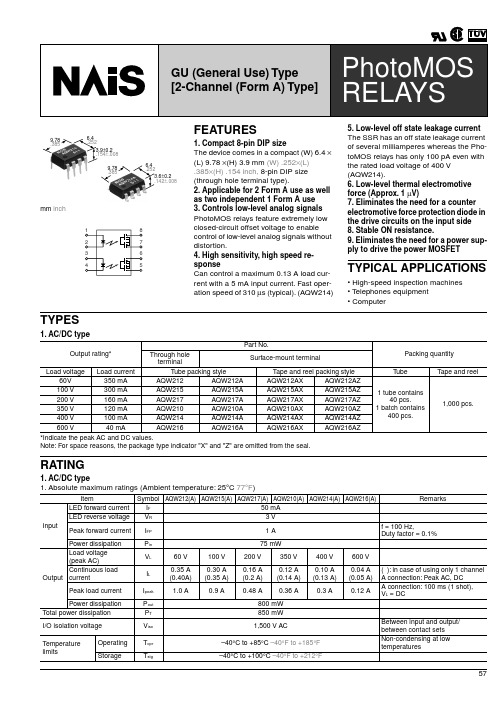
0.9 mA
IFon
IL = Max.
3 mA
0.4 mA
IFoff
IL = Max.
0.8 mA
1.14 V (1.25 V at IF = 50 mA)
VF
IF = 5 mA
1.5 V
0.83 Ω
2.3 Ω
Ron
2.5 Ω
4.0 Ω
11 Ω 15 Ω
23 Ω 35 Ω
30 Ω 50 Ω
70 Ω 120 Ω
AQW214AZ AQW216AZ
*Indicate the peak AC and DC values. Note: For space reasons, the package type indicator "X" and "Z" are omitted from the seal.
Packing quantity
3V
1A
f = 100 Hz, Duty factor = 0.1%
Power dissipation
P in
75 mW
Load voltage (peak AC)
VL
60 V
100 V
200 V
350 V
400 V
600 V
Continuous load Output current
Peak load current
I peak
1.0 A
0.9 A
0.48 A 0.36 A
0.3 A
0.12 A
A connection: 100 ms (1 shot), VL = DC
Power dissipation
P out
2SA1015中文资料(Unisonic Technologies)中文数据手册「EasyDatasheet - 矽搜」
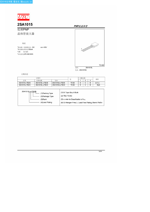
BL 350-700
2of 4
芯片中文手册,看全文,戳
2SA1015
典型特征
静态特性
-50
-40
I =-300µA
-30 I =-250µA
-20
I =-200µA
I =-150µA
-10
I =-100µA
I =-50µA
0
-0
-4 -8 -12 -16 -20
集电极 - 发射极电压,BV
饱和电压
-10 I =10xI
-10 -10 (mA)
-10
V
-10
V
-10 -10
-10 -10 集电极电流,I
集电极输出电容
-10 f=1MHz -10 I =0
-10 -10 (mA)
-10
-10
-10
-10
-10
-10
集电极基极电压,BV
-10 (V)
3of 4
芯片中文手册,看全文,戳
4of 4
FE1
Y 120-240
GR 200-400
额定值
单元
-50
V
-50
V
-5
V
-150
mA
-50
mA
400
mW
125
°C
-55 ~ +125
°C
MIN TYP 最大单位
-50
V
-50
V
-5
V
-100 nA
-100 nA
120
700
25
-0.1 -0.3 V
-1.1 V
4.0 7.0 pF
80
MHz
0.5 6 dB
2SK1273中文资料(Guangdong Kexin)中文数据手册「EasyDatasheet - 矽搜」

打标
打标
NA
SOT-89
12 3
符号
等级
Unit
VDSS
60
V
VGSS
20
V
ID
2.0
A
ID
4.0
A
PD
2.0
W
Байду номын сангаас
Tch
150
Tstg
-55到+150
1 Gate 2 Drain 3 Source
符号
Testconditons
IDSS VDS=60V,V GS=0
IGSS VGS= 20V,V DS=0
可能通过省略biasresistor减少部件数量.
绝对最大额定值大= 25
参数 漏极至源极电压 门源电压
漏电流(DC) 漏极电流(脉冲)*
功耗 通道温度 储存温度
* PW 10毫秒,占空比
50%
电气特性钽= 25
参数 排水截止电流 栅极漏电流 门源截止电压 远期转移导纳
漏极至源极导通状态电阻
输入电容 输出电容 反向传输电容 导通延迟时间 上升时间 关断延迟时间 下降时间
VGS(off) VDS=10V,I D=1mA
Yfs VDS=10V,I D=0.5A
VGS=4.0V,I D=0.5A RDS(on)
VGS=10V,I D=0.5A
Ciss
Coss VDS=10V,V GS=0,f=1MHZ
Crss
td(on)
tr ID=0.5A,V GS(on) =10V,R L=50 td(off) ,VDD=25V,R G=10
芯片中文手册,看全文,戳
SMD型
MOSFET
EN27C512中文资料(List Unclassifed)中文数据手册「EasyDatasheet - 矽搜」

4
芯片中文手册,看全文,戳
EN27C512
READ模式
该EN27C512具有两个控制功能,这两者必须逻辑满足以
获得在输出数据.芯片使能(
CE )是功率控制和应当用于
设备选择.输出使能(
OE )是输出控制和应使用栅极数据到
输出引脚,独立设备选择.假定地址是稳定,
地址访问时间(t
ACC )等于从延迟
在进入编程模式时12.75
± 0.25V被施加到
CE 是在V IL.用于编程,要编程数据被应用于与8位并行 数据引脚.
OE /VPP 销和
图5中QUIKRITE程TM序流程图显示EON交互式编程
算法.交互式算法采用20减少编程时间
编程脉冲和给每个地址仅尽可能多脉冲,是必要,以便
可靠地进行编程数据.之后每个脉冲被施加到一个给定地址,在该数据
30毫安操作(最大)
CMOS-和TTL兼容I / O
高可靠性CMOS技术
闭锁抗扰度100mA电流
从-1V到V CC + 1V二线控制(Βιβλιοθήκη OE & CE )
标准产品识别码
JEDEC标准引脚
28引脚PDIP
32引脚PLCC
28引脚TSOP(类型1)
商业和工业温度 范围
概述
所述EN27C512是一个低功率512Kbit,5V-只有一次性可编程(OTP)只读
芯片中文手册,看全文,戳
EN27C512 512KBIT EPROM (64K x 8)
EN27C512
特征
快速读取时间
:
-45,-55,-70,和-90ns
5V单电源供电
编程电压+ 12.75V
SoMachine Basic中文培训手册
viii
SoMachine Basic 版本 1
2013 年 9 月
课程开始前(续)
启动和测试
在施行本培训时,在电气控制和自动化设备的设计和安装后、使用前,必须由符 合资格的人员对应用和相关功能性安全系统执行一项启动测试,以核实设备的正 确运行。重要的是,要安排执行此项测试,并留出足够的时间以执行完全和合格 的测试。
注意:
与作业点保护相关的互锁和安全措施的协调不在本培训文档的实例和建议实施措 施范围内。
有时候可能会错误调试设备,也许会造成不满意或不安全的操作。总是使用制造 商指示作为功能性调试的指南。可以进行该类调试的人员必须熟悉设备制造商指 示以及与该电气设备一同使用的机械装置。
x
SoMachine Basic 版本 1
有效性注意事项
当前的手册适用于负责所述产品实施、操作和维护的合资格技术人员。它包含合理使用产品所需了解的信息。
关于我们
施耐德电气的教学设计小组成员具有教育学、教育课程开发的三级资格,也是经验丰富的教员。目前,该小组正在从事一系列多 语言、多软件环境的施耐德电气课程的开发和教学。
作者
Richard Irons
符合资格的人员指的是具备电气设备的构建和操作,以及安装方面的相关技能和 知识,并已接受安全培训,能够识别并规避相关危险的人员。
iv
SoMachine Basic 版本 1
2013 年 9 月
课程开始前
本培训手册 的范围
本培训手册是对授权培训的一项补充。为了正确使用软件,学员应同时参考产品 提供的文档,如帮助文件、用户指南或知识库。
SoMachine Basic
手册 第 1 次发布
2SA1215中文资料(sanken)中文数据手册「EasyDatasheet - 矽搜」
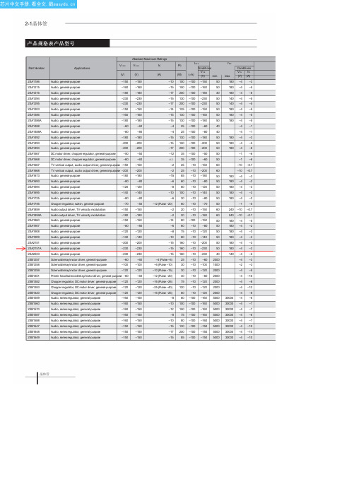
Chopper regulator, DC motor driver, general-purpose –120
Chopper regulator, DC motor driver, general-purpose –120
Audio, seriesregulator, general-purpose
–100 –160 5000
–100 –160 5000
–100 –160 5000
–100 –160 5000
–100 –160 5000
–100 –150 5000
–100 –150 5000
–100 –150 5000
hFE max
Conditions VCE Ic (V) (A)
180 –4 –3
–150
Audio output driver, TV velocity modulation
–180
Audio, general-purpose
–150
Audio, general-purpose
–80
Audio, general-purpose
–120
Audio, general-purpose
–80
Audio, general-purpose
–120
Audio, general-purpose
–140
Audio, general-purpose
–80
Chopper regulator, switch, general-purpose
–70
Audio output driver, TV velocity modulation
VCBO Applications
(V)
ZSSC3122AA2R中文资料(ZMDI)中文数据手册「EasyDatasheet - 矽搜」

描述 ZSSC3122 cLite™ die — Temperature range: -40°C to +125°C ZSSC3122 cLite™ die — Temperature range: -40°C to +125°C ZSSC3122 cLite™ TSSOP14 — Temperature range: -40°C to +125°C – Lead-free package
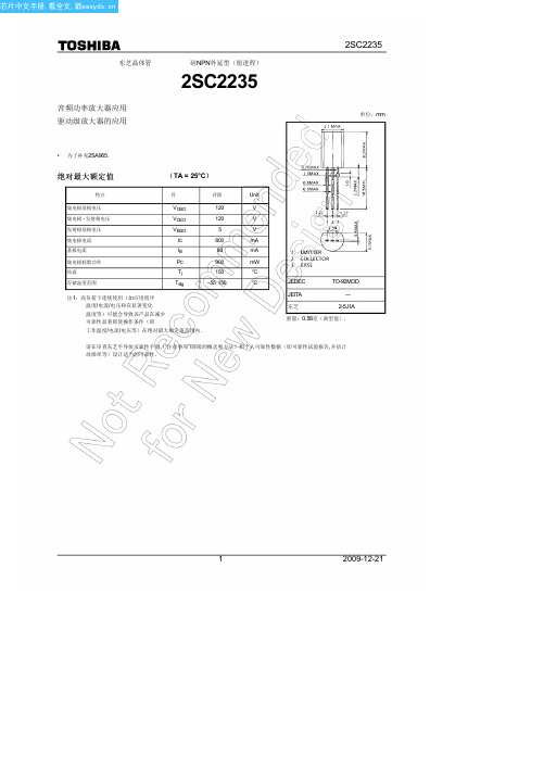
2SC2235中文资料(toshiba)中文数据手册「EasyDatasheet - 矽搜」
10
3
10
30
100
300
1000
Collector current I C (mA)
VCE (sat) – IC
0.5 Common emitter
0.3 IC/IB = 10
(V)
Collector-e0m.1itter
saturation
Ta = 100°C voltage
芯片中文手册,看全文,戳
Байду номын сангаас
东芝晶体管
音频功率放大器应用 驱动级放大器的应用
硅NPN外延型(厘进程)
2SC2235
2SC2235
单位:mm
• 为了补充2SA965.
绝对最大额定值
(TA = 25°C)
特点
符
评级
Unit
集电极基极电压
集电极 - 发射极电压
发射极基极电压 集电极电流 基极电流 集电极耗散功率 结温 存储温度范围
• 请联系您的东芝销售代表联系,以环境问题,如产品的RoHS指令的兼容性. 请遵守产品使用与规范纳入或使用受控物质,包括但不限于,欧盟RoHS指令的所有适用的法律和法规.东芝对出现的不遵守适用的法律法规而导致的损害或 损失不承担任何责任.
4
2009-12-21
V (BR) EBO IE = 1毫安,我C = 0
hFE (注2)
VCE = 5 V, I C =百毫安
VCE (sat) VBE fT Cob
IC = 500毫安,我B =50毫安 VCE = 5 V, I C =500毫安 VCE = 5 V, I C =百毫安 VCB = 10 V, I E = 0,F = 1兆赫
S-81227中文资料

元器件交易网ContentsFeatures (1)Applications (1)Pin Assignment (1)Block Diagram (1)Selection Guide (2)Absolute Maximum Ratings (2)Electrical Characteristics (3)Test Circuits (11)Technical Terms (12)Operation (13)Transient Response (14)Standard Circuit (17)Application Circuits (17)Notes on Design (19)Dimensions (20)Markings (20)Package Power Dissipation (21)Taping Dimensions (22)Characteristics (25)Measuring Circuits (31)Frequently Asked Question s (32)Seiko Instruments Inc.1The S-812XXSG Series is a three-terminal positive voltage regulator made using the CMOS process. Since the S-812XXSG Series has higher precision output voltage and consumes less current than existing three-terminal voltage regulators, battery-powered portable equipment can have a higher performance and a longer service life.ApplicationsConstant voltage power supply of battery-powered equipment, communications equipment, video equipmentand othersPin AssignmentHIGH-PRECISIONVOLTAGE REGULATORS-812XXSG SeriesFeaturesLow power consumption (2.5 A max.) High accuracy of output voltage±2% : V OUT 2.7 V ±2.4% : V OUT 2.6 VSmall input/output voltage difference(S-81250SG: 160 mV typ. I OUT =10 mA) Low temperature coefficient of output voltage(S-81250SG: ±0.625 mV/ C typ.) Wide operating voltage range(S-81250SG: 16 V max.) Good line regulation(S-81250SG: 40 mV typ. I OUT =1 A to 40 mA) T O-92, SOT-89-3 and SOT-23-5 packageBlock DiagramFigure 1R LGNDV INV OUT2+-*Ref.vol.31* Parasitic diodeBottom view123(1)TO-921GND 2V IN 3V OUTTop view1231GND 2V IN 3V OUT(2)SOT-89-3GNDV IN V OUTNC NCTop View (3)SOT-23-5Figure 2HIGH PRECISION VOLTAGE REGULATOR S-812XXSG Series2Seiko Instruments Inc.Selection GuideTable 1Output voltage TO-92 *1SOT-89-3 *2SOT-23-5 *21.1 2.4%S-81211SGY-X S-81211SGUP-DQA-X S-81211SG-QA-X 1.5 2.4%S-81215SGY-XS-81215SGUP-DQK-XS-81215SG-QK-X 1.7 2.4%S-81217SG-QQ-X 1.8 2.4%S-81218SG-QR-X 2.0 2.4%S-81220SGY-X S-81220SGUP-DQS-X S-81220SG-QS-X 2.1 2.4%S-81221SGUP-DQU-X 2.3 2.4%S-81223SGY-X S-81223SG-QW-X 2.4 2.4%S-81224SGY-X S-81224SGUP-DQX-X S-81224SG-QX-X 2.5 2.4%S-81225SGY-X S-81225SGUP-DQH-X S-81225SG-QH-X 2.7 2.0%S-81227SGUP-DQZ-X 3.0 2.0%S-81230SGY-X S-81230SGUP-DQB-X S-81230SG-QB-X 3.3 2.0%S-81233SGY-X S-81233SGUP-DQF-X S-81233SG-QF-X 3.5 2.0%S-81235SGY-X S-81235SGUP-DQI-X S-81235SG-QI-X 3.6 2.0%S-81236SGUP-DQ7-X 3.7 2.0%S-81237SGY-X S-81237SGUP-DQE-X S-81237SG-QE-X 4.0 2.0%S-81240SGY-X S-81240SGUP-DQJ-X S-81240SG-QJ-X 4.2 2.0%S-81242SG-IB-X 4.5 2.0%S-81245SGY-X S-81245SGUP-DQ5-X S-81245SG-Q5-X 4.6 2.0%S-81246SGY-X S-81246SGUP-DQM-X S-81246SG-QM-X 4.7 2.0%S-81247SG-IE-X 5.0 2.0%S-81250SGY-X S-81250SGUP-DQD-X S-81250SG-QD-X 5.2 2.0%S-81252SGY-XS-81252SGUP-DQL-X S-81252SG-QL-X5.3 2.0%S-81253SGUP-DIJ-X 5.4 2.0%S-81254SGUP-DIK-X 5.5 2.0%S-81255SGUP-DIL-X 5.6 2.0%S-81256SGUP-DIM-X*1In the TO-92 package, “x” differs depending upon the packaging form:B : Loose T, Z : Tape*2In the SOT package, “x” differs depending upon the packaging form (in the SOT-23-5 package, on-tape packed products only):S : StickT : Tape (T1 and T2 are available depending upon the direction of the IC)Absolute Maximum RatingsTable 2(Unless otherwise specified: Ta=25 C)ParameterSymbol Conditions Ratings Unit V OUT 2.6 V 12V Input voltage V IN V OUT 2.7 V18Output voltage V OUT V IN +0.3 to V SS -0.3V Output current I OUT 100mA TO-92400Power dissipation P D SOT-89-3500mW SOT-23-5150Operating temperature T opr -40 to +85 C Storage temperatureT stg-40 to +125CCaution: Keep static electricity to a minimum.HIGH-PRECISION VOLTAGE REGULATORS-812XXSG SeriesSeiko Instruments Inc.3Electrical Characteristics1.S-81211SGY-X, S-81211SGUP-DQA-X, S-81211SG-QA-X (1.1-V output type)Parameter Symbol ConditionsMin.Typ.Max.Unit Test cir.Output voltage V OUT V IN =1.5 V, I OUT =0.5 mA 1.073 1.100 1.127V 1I/O voltage difference V dif I OUT =0.5 mA 0.050.2V 1Line regulation 1 V OUT 1V IN =1.5 to 10 V I OUT =0.5 mA 1050mV 1Line regulation 2 V OUT 2V IN =1.5 to 10 V I OUT =10 A1077mV 1Load regulation V OUT 3V IN =1.5 VI OUT =10 A to 0.5 mA 10100mV 1Current consumption I SS V IN =1.5 V, Unloaded1.22.5 A 2Input voltage V IN 10V Temperature charac-teristic of V OUTV OUT TaV IN =1.5 V, I OUT = 0.5 mA Ta=-40 C to 85 C±0.138mV/ C2. S-81215SGY-X, S-81215SGUP-DQK-X, S-81215SG-QK-X (1.5-V output type)Parameter Symbol ConditionsMin.Typ.Max.Unit Test cir.Output voltage V OUT V IN =3.5 V, I OUT =0.5 mA 1.464 1.500 1.536V 1I/O voltage difference V dif I OUT =0.5 mA 0.030.18V 1Line regulation 1 V OUT 1V IN =2.5 to 10 V I OUT =0.5 mA 739mV 1Line regulation 2 V OUT 2V IN =2.5 to 10 V I OUT =1 A7105mV 1Load regulation V OUT 3V IN =3.5 VI OUT =1 A to10 mA 80120mV 1Current consumption I SS V IN =3.5 V, Unloaded1.22.5 A 2Input voltage V IN 10V Temperature charac-teristic of V OUTV OUT TaV IN =3.5 V, I OUT = 0.5 mA Ta=-40 C to 85 C±0.188mV/ C3. S-81217SG-QQ-X (1.7-V output type)Parameter Symbol ConditionsMin.Typ.Max.Unit Test cir.Output voltage V OUT V IN =3.7 V, I OUT =10 mA 1.659 1.700 1.741V 1I/O voltage difference V dif I OUT =10 mA 0.77 1.63V 1Line regulation 1 V OUT 1V IN =2.7 to 10 V I OUT =1 mA 843mV 1Line regulation 2 V OUT 2V IN =2.7 to 10 V I OUT =1 A8119mV 1Load regulation V OUT 3V IN =3.7 VI OUT =1 A to 10 mA 80120mV 1Current consumption I SS V IN =3.7 V, Unloaded1.22.5 A 2Input voltage V IN 10V Temperature charac-teristic of V OUTV OUT TaV IN =3.7 V, I OUT = 10 mA Ta=-40 C to 85 C±0.213mV/ CTable 3(Unless otherwise specified: Ta=25 C)Table 4(Unless otherwise specified: Ta=25 C)Table 5(Unless otherwise specified: Ta=25 C)HIGH PRECISION VOLTAGE REGULATOR S-812XXSG Series4Seiko Instruments Inc.4.S-81218SG-QR-X (1.8-V output type)Parameter Symbol ConditionsMin.Typ.Max.Unit Test cir.Output voltage V OUT V IN =3.8 V, I OUT =10 mA 1.756 1.800 1.843V 1I/O voltage difference V dif I OUT =10 mA 0.72 1.55V 1Line regulation 1 V OUT 1V IN =2.8 to 10 V I OUT =1 mA 845mV 1Line regulation 2 V OUT 2V IN =2.8 to 10 V I OUT =1 A8126mV 1Load regulation V OUT 3V IN =3.8 VI OUT =1 A to 10 mA 80120mV 1Current consumption I SS V IN =3.8 V, Unloaded1.22.5 A 2Input voltage V IN 10V Temperature charac-teristic of V OUTV OUT TaV IN =3.8 V, I OUT = 10 mA Ta=-40 C to 85 C±0.225mV/ C5.S-81220SGY-X, S-81220SGUP-DQS-X, S-81220SG-QS-X (2.0-V output type)Parameter Symbol ConditionsMin.Typ.Max.Unit Test cir.Output voltage V OUT V IN =4.0 V, I OUT =10 mA 1.592 2.000 2.048V 1I/O voltage difference V dif I OUT =10 mA 0.63 1.39V 1Line regulation 1 V OUT 1V IN =3.0 to 10 V I OUT =1 mA 848mV 1Line regulation 2 V OUT 2V IN =3.0 to 10 V I OUT =1 A8140mV 1Load regulation V OUT 3V IN =4.0 VI OUT =1 A to 10 mA 80120mV 1Current consumption I SS V IN =4.0 V, Unloaded1.22.5 A 2Input voltage V IN 10V Temperature charac-teristic of V OUTV OUT TaV IN =4.0 V, I OUT = 10 mA Ta=-40 C to 85 C±0.250mV/ C6.S-81221SGUP-DQU-X (2.1-V output type)Parameter Symbol ConditionsMin.Typ.Max.Unit Test cir.Output voltage V OUT V IN =4.1 V, I OUT =10 mA 2.049 2.100 2.151V 1I/O voltage difference V dif I OUT =10 mA 0.59 1.32V 1Line regulation 1 V OUT 1V IN =3.1 to 10 V I OUT =1 mA 950mV 1Line regulation 2 V OUT 2V IN =3.1 to 10 V I OUT =1 A9147mV 1Load regulation V OUT 3V IN =4.1 VI OUT =1 A to 10 mA 80120mV 1Current consumption I SS V IN =4.1 V, Unloaded1.22.5 A 2Input voltage V IN 10V Temperature charac-teristic of V OUTV OUT TaV IN =4.1 V, I OU T = 10 mA Ta=-40 C to 85 C±0.263mV/ CTable 6(Unless otherwise specified : Ta=25 C)Table 7(Unless otherwise specified : Ta=25 C)Table 8(Unless otherwise specified : Ta=25 C)HIGH-PRECISION VOLTAGE REGULATORS-812XXSG SeriesSeiko Instruments Inc.57.S-81223SGY-X, S-81223SG-QW-X (2.3-V output type)Parameter Symbol ConditionsMin.Typ.Max.Unit Test cir.Output voltage V OUT V IN =4.3 V, I OUT =10 mA2.244 2.300 2.356V 1I/O voltage difference V dif IOUT =10 mA0.53 1.20V 1Line regulation 1 V OUT 1V IN =3.3 to 10 V I OUT =1 mA 954mV 1Line regulation 2 V OUT 2V IN =3.3 to 10 V I OUT =1 A9161mV 1Load regulation V OUT 3V IN =4.3 VI OUT =1 A to 10 mA 80120mV 1Current consumption I SS V IN =4.3 V, Unloaded1.22.5 A 2Input voltage V IN 10V Temperature charac-teristic of V OUTV OUT TaV IN =4.3 V, I OUT = 10 mA Ta=-40 C to 85 C±0.288mV/ C8.S-81224SGY-X, S-81224SGUP-DQX-X, S-81224SG-QX-X (2.4-V output type)Parameter Symbol ConditionsMin.Typ.Max.Unit Test cir.Output voltage V OUT V IN =4.4 V, I OUT =10 mA 2.342 2.400 2.458V 1I/O voltage difference V dif I OUT =10 mA 0.49 1.15V 1Line regulation 1 V OUT 1V IN =3.4 to 10 V I OUT =1 mA 1055mV 1Line regulation 2 V OUT 2V IN =3.4 to 10 V I OUT =1 A10168mV 1Load regulation V OUT 3V IN =4.4 VI OUT =1 A to 10 mA 80120mV 1Current consumption I SS V IN =4.4 V, Unloaded1.22.5 A 2Input voltage V IN 10V Temperature charac-teristic of V OUTV OUT TaV IN =4.4 V, I OUT = 10 mA Ta=-40 C to 85 C±0.300mV/ C9.S-81225SGY-X, S-81225SGUP-DQH-X, S-81225SG-QH-X (2.5-V output type)Parameter Symbol ConditionsMin.Typ.Max.Unit Test cir.Output voltage V OUT V IN =4.5 V, I OUT =10 mA 2.440 2.500 2.560V 1I/O voltage difference V dif I OUT =10 mA 0.59 1.32V 1Line regulation 1 V OUT 1V IN =3.5 to 10 V I OUT =1 mA 1057mV 1Line regulation 2 V OUT 2V IN =3.5 to 10 V I OUT =1 A10175mV 1Load regulation V OUT 3V IN =4.5 VI OUT =1 A to 10 mA 80120mV 1Current consumption I SS V IN =4.5 V, Unloaded1.22.5 A 2Input voltage V IN 10V Temperature charac-teristic of V OUTV OUT TaV IN =4.5 V, I OUT = 10 mA Ta=-40 C to 85 C±0.313mV/ CTable 9(Unless otherwise specified : Ta=25 C)Table 10(Unless otherwise specified : Ta=25 C)Table 11(Unless otherwise specified : Ta=25 C)HIGH-PRECISION VOLTAGE REGULATOR S-812XXSG Series6Seiko Instruments Inc.10.S-81227SGUP-DQZ-X (2.7-V output type)Parameter Symbol ConditionsMin.Typ.Max.Unit Test cir.Output voltage V OUT V IN =4.7 V, I OUT =10 mA 2.646 2.700 2.754V 1I/O voltage difference V dif I OUT =10 mA 0.52 1.20V 1Line regulation 1 V OUT 1V IN =3.7 to 16 V I OUT =1 mA 3672mV 1Line regulation 2 V OUT 2V IN =3.7 to 16 V I OUT =1 A36189mV 1Load regulation V OUT 3V IN =4.7 VI OUT =1 A to 20 mA 80120mV 1Current consumption I SS V IN =4.7 V, Unloaded1.22.5 A 2Input voltage V IN 16V Temperature charac-teristic of V OUTV OUT TaV IN =4.7 V, I OUT = 10 mA Ta=-40 C to 85 C±0.338mV/ C11.S-81230SGY-X, S-81230SGUP-DQB-X, S-81230SG-QB-X (3.0-V output type)Parameter Symbol ConditionsMin.Typ.Max.Unit Test cir.Output voltage V OUT V IN =5.0 V, I OUT =10 mA 2.940 3.000 3.060V 1I/O voltage difference V dif I OUT =10 mA 0.44 1.04V 1Line regulation 1 V OUT 1V IN =4.0 to 16 V I OUT =1 mA 3978mV 1Line regulation 2 V OUT 2V IN =4.0 to 16 V I OUT =1 A39210mV 1Load regulation V OUT 3V IN =5 VI OUT =1 A to 20 mA 60100mV 1Current consumption I SS V IN =5.0 V, Unloaded1.22.5 A 2Input voltage V IN 16V Temperature charac-teristic of V OUTV OUT TaV IN =5.0 V, I OUT = 10 mA Ta=-40 C to 85 C±0.375mV/ C12.S-81233SGY-X, S-81233SGUP-DQF-X, S-81233SG-QF-X (3.3-V output type)Parameter Symbol ConditionsMin.Typ.Max.Unit Test cir.Output voltage V OUT V IN =5.3 V, I OUT =10 mA 3.234 3.300 3.366V 1I/O voltage difference V dif I OUT =10 mA 0.370.91V 1Line regulation 1 V OUT 1V IN =4.3 to 16 V I OUT =1 mA 4284mV 1Line regulation 2 V OUT 2V IN =4.3 to 16 V I OUT =1 A42231mV 1Load regulation V OUT 3V IN =5.3 VI OUT =1 A to 20 mA 60100mV 1Current consumption I SS V IN =5.3 V, Unloaded1.22.5 A 2Input voltage V IN 16V Temperature charac-teristic of V OUTV OUT TaV IN =5.3 V, I OUT = 10 mA Ta=-40 C to 85 C±0.413mV/ CTable 12(Unless otherwise specified : Ta=25 C)Table 13(Unless otherwise specified : Ta=25 C)Table 14(Unless otherwise specified : Ta=25 C)HIGH-PRECISION VOLTAGE REGULATORS-812XXSG SeriesSeiko Instruments Inc.713.S-81235SGY-X, S-81235SGUP-DQI-X, S-81235SG-QI-X (3.5-V output type)Parameter Symbol ConditionsMin.Typ.Max.Unit Test cir.Output voltage V OUT V IN =5.5 V, I OUT =10 mA 3.430 3.500 3.570V 1I/O voltage difference V dif I OUT =10 mA 0.340.84V 1Line regulation 1 V OUT 1V IN =4.5 to 16 V I OUT =1 mA 4488mV 1Line regulation 2 V OUT 2V IN =4.5 to 16 V I OUT =1 A44245mV 1Load regulation V OUT 3V IN =5.5 VI OUT =1 A to 30 mA 60100mV 1Current consumption I SS V IN =5.5 V, Unloaded1.22.5 A 2Input voltage V IN 16V Temperature charac-teristic of V OUTV OUT TaV IN =5.5 V, I OUT = 10 mA Ta=-40 C to 85 C±0.438mV/ C14. S-81236SGUP-DQ7-X (3.6-V output type)Parameter Symbol ConditionsMin.Typ.Max.Unit Test cir.Output voltage V OUT V IN =5.6 V, I OUT =10 mA 3.528 3.600 3.672V 1I/O voltage difference V dif I OUT =16 mA 0.320.81V 1Line regulation 1 V OUT 1V IN =4.6 to 16 V I OUT =1 mA 4590mV 1Line regulation 2 V OUT 2V IN =4.6 to 16 V I OUT =1 A45252mV 1Load regulation V OUT 3V IN =5.6 VI OUT =1 A to 30 mA 60100mV 1Current consumption I SS V IN =5.6 V, Unloaded1.22.5 A 2Input voltage V IN 16V Temperature charac-teristic of V OUTV OUT TaV IN =5.6 V, I OUT = 10 mA Ta=-40 C to 85 C±0.450mV/ C15.S-81237SGY-X, S-81237SGUP-DQE-X, S-81237SG-QE-X (3.7-V output type)Parameter Symbol ConditionsMin.Typ.Max.Unit Test cir.Output voltage V OUT V IN =5.7 V, I OUT =10 mA 3.626 3.700 3.774V 1I/O voltage difference V dif I OUT =10 mA 0.310.78V 1Line regulation 1 V OUT 1V IN =4.7 to 16 V I OUT =1 mA 4692mV 1Line regulation 2 V OUT 2V IN =4.7 to 16 V I OUT =1 A46259mV 1Load regulation V OUT 3V IN =5.7 VI OUT =1 A to 30 mA 60100mV 1Current consumption I SS V IN =5.7 V, Unloaded1.22.5 A 2Input voltage V IN 16V Temperature charac-teristic of V OUTV OUT TaV IN =5.7 V, I OUT = 10 mA Ta=-40 C to 85 C±0.463mV/ CTable 15(Unless otherwise specified : Ta=25 C)Table 17(Unless otherwise specified : Ta=25 C)Table 16(Unless otherwise specified : Ta=25 C)HIGH-PRECISION VOLTAGE REGULATOR S-812XXSG Series8Seiko Instruments Inc.16.S-81240SGY-X, S-81240SGUP-DQJ-X, S-81240SG-QJ-X (4.0-V output type)Parameter Symbol ConditionsMin.Typ.Max.Unit Test cir.Output voltage V OUT V IN =6.0 V, I OUT =10 mA 3.920 4.000 4.080V 1I/O voltage difference V dif I OUT =10 mA 0.270.70V 1Line regulation 1 V OUT 1V IN =5.0 to 16 V I OUT =1 mA 4896mV 1Line regulation 2 V OUT 2V IN =5.0 to 16 V I OUT =1 A48280mV 1Load regulation V OUT 3V IN =6.0 VI OUT =1 A to 30 mA 5090mV 1Current consumption I SS V IN =6.0 V, Unloaded1.22.5 A 2Input voltage V IN 16V Temperature charac-teristic of V OUTV OUT TaV IN =6.0 V, I OUT = 10 mA Ta=-40 C to 85 C±0.500mV/ C17. S-81242SG-IB-X (4.2-V output type)Parameter Symbol ConditionsMin.Typ.Max.Unit Test cir.Output voltage V OUT V IN =6.2V, I OUT =10 mA 4.116 4.200 4.284V 1I/O voltage difference V dif I OUT =10 mA 0.240.65V 1Line regulation 1 V OUT 1V IN =5.2 to 16 V I OUT =1 mA 50100mV 1Line regulation 2 V OUT 2V IN =5.2 to 16 V I OUT =1 A50294mV 1Load regulation V OUT 3V IN =6.2 VI OUT =1 A to 30 mA 5090mV 1Current consumption I SS V IN =6.2 V, Unloaded1.22.5 A 2Input voltage V IN 16V Temperature charac-teristic of V OUTV OUT TaV IN =6.2 V, I OUT = 10 mA Ta=-40 C to 85 C±0.525mV/ C18.S-81245SGY-X, S-81245SGUP-DQ5-X, S-81245SG-Q5-X (4.5-V output type)Parameter Symbol ConditionsMin.Typ.Max.Unit Test cir.Output voltage V OUT V IN =6.5 V, I OUT =10 mA 4.410 4.500 4.590V 1I/O voltage difference V dif I OUT =10 mA 0.210.58V 1Line regulation 1 V OUT 1V IN =5.5 to 16 V I OUT =1 mA 52104mV 1Line regulation 2 V OUT 2V IN =5.5 to 16 V I OUT =1 A52315mV 1Load regulation V OUT 3V IN =6.5 VI OUT =1 A to 30 mA 5090mV 1Current consumption I SS V IN =6.5 V, Unloaded1.22.5 A 2Input voltage V IN 16V Temperature charac-teristic of V OUTV OUT TaV IN =6.5 V, I OUT = 10 mA Ta=-40 C to 85 C±0.563mV/ CTable 18(Unless otherwise specified : Ta=25 C)Table 20(Unless otherwise specified : Ta=25 C)Table 19(Unless otherwise specified : Ta=25 C)HIGH-PRECISION VOLTAGE REGULATORS-812XXSG SeriesSeiko Instruments Inc.919.S-81246SGY-X, S-81246SGUP-DQM-X, S-81246SG-QM-X (4.6-V output type)Parameter Symbol ConditionsMin.Typ.Max.Unit Test cir.Output voltage V OUT V IN =6.6 V, I OUT =10 mA 4.508 4.600 4.692V 1I/O voltage difference V dif I OUT =10 mA 0.200.57V 1Line regulation 1 V OUT 1V IN =5.6 to 16 V I OUT =1 mA 53105mV 1Line regulation 2 V OUT 2V IN =5.6 to 16 V I OUT =1 A53322mV 1Load regulation V OUT 3V IN =6.6 VI OUT =1 A to 30 mA 5090mV 1Current consumption I SS V IN =6.6 V, Unloaded1.22.5 A 2Input voltage V IN 16V Temperature charac-teristic of V OUTV OUT TaV IN =6.6 V, I OUT = 10 mA Ta=-40 C to 85 C±0.575mV/ C20.S-81247SG-IE-X (4.7-V output type)Parameter Symbol ConditionsMin.Typ.Max.Unit Test cir.Output voltage V OUT V IN =6.7 V, I OUT =10 mA 4.606 4.700 4.794V 1I/O voltage difference V dif I OUT =10 mA 0.190.55V 1Line regulation 1 V OUT 1V IN =5.7 to 16 V I OUT =1 mA 54107mV 1Line regulation 2 V OUT 2V IN =5.7 to 16 V I OUT =1 A54329mV 1Load regulation V OUT 3V IN =6.7 VI OUT =1 A to 30 mA 5090mV 1Current consumption I SS V IN =6.7 V, Unloaded1.22.5 A 2Input voltage V IN 16V Temperature charac-teristic of V OUTV OUT TaV IN =6.7 V, I OUT = 10 mA Ta=-40 C to 85 C±0.588mV/ C21.S-81250SGY-X, S-81250SGUP-DQD-X, S-81250SG-QD-X (5.0-V output type)Parameter Symbol ConditionsMin.Typ.Max.Unit Test cir.Output voltage V OUT V IN =7.0 V, I OUT =10 mA 4.900 5.000 5.100V 1I/O voltage difference V dif I OUT =10 mA 0.160.50V 1Line regulation 1 V OUT 1V IN =6.0 to 16 V I OUT =1 mA 55110mV 1Line regulation 2 V OUT 2V IN =6.0 to 16 V I OUT =1 A55350mV 1Load regulation V OUT 3V IN =7.0 VI OUT =1 A to 40 mA 4080mV 1Current consumption I SS V IN =7.0 V, Unloaded1.22.5 A 2Input voltage V IN 16V Temperature charac-teristic of V OUTV OUT TaV IN =7.0 V, I OUT = 10 mA Ta=-40 C to 85 C±0.625mV/ CTable 21(Unless otherwise specified : Ta=25 C)Table 22(Unless otherwise specified : Ta=25 C)Table 23(Unless otherwise specified : Ta=25 C)22.S-81252SGY-X, S-81252SGUP-DQL-X, S-81252SG-QL-X (5.2-V output type)Parameter Symbol Conditions Min.Typ.Max.Unit Testcir.Output voltage V OUT V IN =7.2 V, I OUT =10 mA 5.096 5.200 5.304V1 I/O voltage difference V dif I OUT=10 mA 0.150.47V1 Line regulation 1 V OUT1V IN =6.2 to 16 VI OUT=1 mA57113mV1Line regulation 2 V OUT2V IN =6.2 to 16 VI OUT=1 A57364mV1Load regulation V OUT3V IN =7.2 VI OUT=1 A to 40 mA4080mV1 Current consumption I SS V IN =7.2 V, Unloaded 1.2 2.5 A2 Input voltage V IN 16VTemperature charac-teristic of V OUT V OUTTaV IN=7.2 V, I OUT = 10 mATa=-40 C to 85 C±0.650 mV/ C23.S-81253SGUP-DIJ-X (5.3-V output type)Parameter Symbol Conditions Min.Typ.Max.Unit Testcir.Output voltage V OUT V IN =7.3 V, I OUT =10 mA 5.194 5.300 5.406V1 I/O voltage difference V dif I OUT=10 mA 0.140.45V1 Line regulation 1 V OUT1V IN =6.3 to 16 VI OUT=1 mA57114mV1Line regulation 2 V OUT2V IN =6.3 to 16 VI OUT=1 A57371mV1Load regulation V OUT3V IN =7.3 VI OUT=1 A to 40 mA4080mV1 Current consumption I SS V IN =7.3 V, Unloaded 1.2 2.5 A2 Input voltage V IN 16VTemperature charac-teristic of V OUT V OUTTaV IN=7.3 V, I OUT = 10 mATa=-40 C to 85 C±0.663 mV/ C24.S-81254SGUP-DIK-X (5.4-V output type)Parameter Symbol Conditions Min.Typ.Max.Unit Testcir.Output voltage V OUT V IN =7.4 V, I OUT =10 mA 5.292 5.400 5.508V1 I/O voltage difference V dif I OUT=10 mA 0.130.44V1 Line regulation 1 V OUT1V IN =6.4 to 16 VI OUT=1 mA58115mV1Line regulation 2 V OUT2V IN =6.4 to 16 VI OUT=1 A58378mV1Load regulation V OUT3V IN =7.4 VI OUT=1 A to 40 mA4080mV1 Current consumption I SS V IN =7.4 V, Unloaded 1.2 2.5 A2 Input voltage V IN 16VTemperature charac-teristic of V OUT V OUTTaV IN=7.4 V, I OUT = 10 mATa=-40 C to 85 C±0.675 mV/ CTable 24(Unless otherwise specified: Ta=25 C)Table 25(Unless otherwise specified: Ta=25 C)Table 26(Unless otherwise specified: Ta=25 C)25.S-81255SGUP-DIL-X (5.5-V output type)Parameter Symbol Conditions Min.Typ.Max.Unit Testcir.Output voltage V OUT V IN =7.5 V, I OUT =10 mA 5.390 5.500 5.610V 1 I/O voltage difference V dif I OUT=10 mA 0.130.43V1 Line regulation 1 V OUT1V IN =6.5 to 16 VI OUT=1 mA58116mV1Line regulation 2 V OUT2V IN =6.5 to 16 VI OUT=1 A58385mV1Load regulation V OUT3V IN =7.5 VI OUT=1 A to 40 mA4080mV1 Current consumption I SS V IN =7.5 V, Unloaded 1.2 2.5 A2 Input voltage V IN 16VTemperature charac-teristic of V OUT V OUTTaV IN=7.5 V, I OUT = 10 mATa=-40 C to 85 C±0.688 mV/ C26.S-81256SGUP-DIM-X (5.6-V output type)Parameter Symbol Conditions Min.Typ.Max.Unit Testcir.Output voltage V OUT V IN =7.6 V, I OUT =10 mA 5.488 5.600 5.712V1 I/O voltage difference V dif I OUT=10 mA 0.120.42V1 Line regulation 1 V OUT1V IN =6.6 to 16 VI OUT=1 mA59117mV1Line regulation 2 V OUT2V IN =6.6 to 16 VI OUT=1 A59392mV1Load regulation V OUT3V IN =7.6 VI OUT=1 A to 40 mA4080mV1 Current consumption I SS V IN =7.6 V, Unloaded 1.2 2.5 A2 Input voltage V IN 16VTemperature charac-teristic of V OUT V OUTTaV IN=7.6 V, I OUT = 10 mATa=-40 C to 85 C±0.7 mV/ CTest CircuitsTable 27(Unless otherwise specified: Ta=25 C)Table 28(Unless otherwise specified: Ta=25 C)Figure 3GND GNDV IN V OUTV IN V OUT12S-812XXSGSeriesV V AVA S-812XXSGSeriesTechnical Terms1Output voltage (V OUT)The precision of output voltage is guaranteed at ±2.0% or ±2.4% under the prescribed conditions of input voltage, output voltage, and temperature, which differ with items. If these conditions are varied, output voltage value may change into beyond the scope of precision of output voltage. See electrical characteristics and characteristicsdata for detail.2Line regulations 1 and 2 ( V OUT1, V OUT2)Indicates the input voltage dependencies of output voltage. That is, the values express how the output voltage changes, when input voltage is changed under the condition that output current is fixed.3Load regulation ( V OUT3)Indicates the output current dependencies of output voltage. That is, the values express how the output voltage changes, when output current is changed under the condition that input voltage is fixed.4I/O voltage defference (V dif)98% of V OUT is output when the voltage of V OUT+V dif is applied. When V dif is small, output keeps a constantvoltage in the small side of input voltage and large output current can be obtained.NOTE : V dif is highly dependent on I OUT.Operation1Basic operationFigure 4 shows the block diagram of the S-812XXSG Series.The error amplifier compares a reference voltage V REF with a part of the output voltage fed back by the feedback resistors R A and R B . It supplies the control transistor with the gate current, necessary to keep a stable output voltage range not influenced by input voltage or temperature fluctuation.V INError amplifierR BR ACurrent source-+V OUTGND*Reference voltage circuit* Parasitic diodeFigure 4 Reference block diagram2Internal circuit2.1Reference voltage circuitIn a voltage regulator, the reference voltage circuit plays a very important role because any change will show up directly at an output.The S-812XXSG Series has 0.8 V typical stable voltage circuit as a highly stable reference voltage source.Features:Low power consumptionGood temperature characteristic2.2Error amplifierThe error amplifier consumes very low current because it is a differential amplifier in a stable current circuit.Features:Good matching characteristics Wide operating voltage range Low offset voltage2.3Control transistorThe S-812XXSG Series has a Pch MOS transistor as a current control transistor shown in Figure 6. Therefore an output current I OUT is expressed by the following formula where is only a small difference between input and output voltages:I OUT =KP{2(V GS -V TP ) (V IN -V OUT )-(V IN -V OUT )2}*KP :Conductive coefficiencyV TP :Threshold voltage of a control transistor Setting KP to the large value results in a voltage regulator with 160 mV typical I/O voltage difference.V IN -V IN +GNDV INV OUTFigure 5 Error amplifierBiasV INV OUTGNDV GSV REF -+** Parasitic diodeFigure 6 Control transistorNOTE :A parasitic diode is generated between V IN and V OUT .If the electric potential of V IN is higher than that of V OUT , IC may break because of a reverse current.Keep V OUT less than V IN +0.3 V.3Temperature characteristic of output voltageThe temperature characteristic of the output voltage is expressed by the following formula in the range of -40 C to 85 C.*V REF is 0.7 V min., 0.8 V typ., 0.9 V max.Transient Response1.Line transient responseThe overshoot and undershoot are caused in the output voltage if the input voltage fluctuates while the output current is constant. Figure 7 shows the output voltage fluctuation due to input voltage change between 6.0 V and 10 V in square wave. Table 19 shows the parameter dependency when input voltage fluctuates. For reference,Figure 8 describes the measurement circuit.Table 29 Parameter dependency due to input voltage fluctuationParameterMethod to decreaseovershootMethod to decreaseundershootOutput currentI OUTDecrease Decrease Load capacitance C L Increase Increase Input voltage fluctuation V IN *DecreaseDecrease TemperatureTaHigh temperature*V IN : High voltage value - low voltage valueFor reference, the next page describes the results of measuring the ringing amounts at the V OUT pin using theoutput current (I OUT ), load capacitance (C L ), input voltage fluctuation width ( V IN ), and temperature as parameters.V REFV OUT x (±0.1) mV/ C typ.Figure 7 Output voltage fluctuation due to input voltage fluctuationInput voltage6.010 VUndershootOvershootOutput voltageFigure 8 Measuring circuitFast amplifierP.G.S-812XXSGOscilloscopeC LV OUTV SSV IN+-- 2.Load transient responseThe overshoot and undershoot are caused in the output voltage if the output current fluctuates while the inputvoltage is costant. Figure 9 shows the output voltage fluctuation due to output current change between 10mA and 1 A in square wave. Table 20 shows the parameter dependency when output current fluctuates. For reference,Figure 10 describes the measuring circuit.Line transient response of S-81250SGReference data1.I OUT dependencyC L =10 F Ta=25 C1.21.00.80.60.40.20.0051015202530Ringing amount(V)I OUT (mA)2.C L dependencyUndershoot OvershootI OUT =10mA Ta=25 C1.21.00.80.60.40.20.00Ringing amount(V)1020304050C L ( F)4.Temperature dependencyUndershoot OvershootI OUT =10mA C L =10 F1.21.00.80.60.40.20.0Ringing amount(V)80400-40Ta ( C)3. V IN dependencyV IN shows the difference between the low voltage fixed to 6 V and the high voltage.For example, V IN = 2 V means the difference between 6 V and 8 V. 1.21.00.80.60.40.20.0Ringing amount(V)1245V IN (V)3C L =10 F Ta=25 CI OUT =10mAFigure 9 Output voltage fluctuation due to output current fluctuationOutput current10mA1 AOutput voltageOvershootUndershootFigure 10 Measuring circuitS-812XXSGOscilloscopeC LV OUT V SSV IN。
ERA中文资料(minicircuits)中文数据手册「EasyDatasheet-矽搜」

ERA中文资料(minicircuits)中文数据手册「EasyDatasheet-矽搜」ERAERA-SM50?低电量,高达+13.5 dBm 范围内输出JFREQ.GHzMODEL u NO.ERA-1ERA-2ERA-3ERA-1SM ERA-21SM ERA-2SM ERA-33SM ERA-3SM ERA-8SMf L - f U DC-8DC-6DC-3DC-8DC-8DC-6DC-3DC-3DC-20.11over frequency, GHz 234688.2——8.28.9————Min.@2 GHz91316911.213151617所有规格在25℃MAXIMUM DYNAMIC POWER (dBm)RANGE at 2 GHz*at 2 GHz*Output Input (1 dB (no Comp.)Typ. Min. dmg)12.0 10.013.0 11.012.5 9.012.0 10.012.6 10.613.0 11.013.5 11.512.5 9.012.5 —151513151515131313GAIN , dB T ypicalVSWR (:1)T yp.In OutNF IP3Device 3-f U** DC-3 3-f U ** I (dB) (dBm) DC-3P Current Volt.Typ. Typ. GHz GHz GHz GHz (mA ) (mW) (mA ) Typ Min Max4.3 264.0 263.5 254.3 264.7 264.0 26 1.5 1.81.3 1.41.5 —1.5 1.81.1 1.41.3 1.4 1.5 1.91.2 1.61.4 —1.5 1.91.3 1.91.2 1.61.25 —1.4 —1.82.275 33075 33075 33075 33075 33075 33075 33075 33065 2504040354040404035363.4 3.04.13.4 3.0 4.13.2 3.0 4.13.4 3.0 4.13.5 3.0 4.13.4 3.0 4.14.3 3.8 4.83.2 3.0 4.13.7 3.2 4.2ABSO-LUT E MAX.RAT ING 3DC OPERAT ING POWER 4at Pin 3T HERMAL CASE RESIS- ST YLE T ANCE θjcTyp.°C/W178155154183194160140159140Note BC O N N E C T I O NPRICE $Qty.(30)12.3 12.1 11.8 10.9 9.7 7.916.2 15.8 15.2 14.4 13.1 11.222.1 21.0 18.7 16.8 ——12.3 12.1 11.8 10.9 9.7 7.914.2 13.9 13.2 12.2 10.8 8.716.2 15.8 15.2 14.4 13.1 11.219.3 18.7 17.4 15.9 —22.1 21.0 18.7 16.8 —31.5 25.0 19.0 15.0 12.0———VV105 cb 1.37VV105 cb 1.52VV105 cb 1.67WW107 cb 1.42WW107 cb 1.57WW107 cb 1.57WW107 cb 1.72WW107 cb 1.72WW107 cb 1.223.9 28.5 1.6 —3.5 25 1.5 —3.1 25 1.4 1.8特征l l l l低热阻小型微波放大器频率范围,直流到8GHz,可用到10GHz高达18.4 dBm 的典型. (16.5 dBm 的分钟)输出功率模型识别M odelERA-1, ERA-1SM ERA-2, ERA-2SM ERA-21SM ERA-3, ERA-3SM ERA-33SM ERA-4,-4SM ERA-4X SM ERA-5, ERA-5SM ERA-50SM ERA-51SM ERA-5X SM ERA-6, ERA-6SM ERA-8SM 记号(s ee note below)122133344X 550515X 6E8绝对最大额定值工作温度:-45°C 至85°C 储存温度:-65℃至150℃Note: Prefix letter (optional) designates assembly———location. Suffix letters (optional) are for w aferidentification.prefix letter number注意:Aqueous was hable at 1 GHz for ERA-4,5,6, 4SM,4XSM ,5SM,5XSM, 50SM, 51SM, 6SM, 8SM.f u is the upper frequency limit for each model as s hown in the table;for ERA-8SM VSW R (In & Out) is s pecified at DC-1GHz & 1-4 GHz.*** Gain and VSW R are s pecified at 1.5 GHz.J Low frequency cutoff determined by external coupling capacitors .A. Environmental s pecifications and re-flow s oldering information available inGeneral Information Section.B. Units are non-hermetic unles s otherwis e noted. For details on cas edimens ions & finis hes s ee “Cas e Styles & Outline Drawings ”.C. Prices and Specifications s ubject to change without notice.D. For Quality Control Procedures s ee Table of Contents , Section 0,"Mini-Circuits Guarantees Quality" article. For Environmental Specifications s ee Amplifier Selection Guide.1. Model number des ignated by alphanumeric code mark ing.2. ERA-SM models available on tape and reel.3. Permanent damage may occur if any of thes e limits are exceeded. Thes eratings are not intended for continuous normal operation.4. Supply voltage mus t be connected to pin 3 through a bias res is tor in orderapplication.html. Reliability predictions are applicable at s pecified current & normal operating conditions .u ***suffix letterMTTF vs. Junction Temp.(For all ERA Models except ERA -5, ERA -5SM)1,000,000100,000平均无故障时间(年)10,0001,00010010180100120140160180 200Junction Temp. (?C)040618插入式及表面贴装ERAERA-SM中等功率,高达18.4 dBm 的输出JFREQ.GHzMODEL u NO.ERA-6ERA-4ERA-5ERA-6SM ERA-4SM NEW ERA-4X SM NEW ERA-5X SM f L - f UDC-4DC-4DC-4DC-4DC-4DC-4DC-40.11over frequency, GHz 234Min.@2 GHz10.5111610.5111216141616所有规格在25℃MAXIMUM DYNAMIC POWER (dBm)RANGE at 2 GHz*at 2 GHz*Output Input (1 dB (no Comp.)Typ. Min. dmg)17.9 1617.3 1518.4 16.517.9 1617.3 1517.0 15.017.8 16.518.1 16.518.4 16.517.2 16.020201320202013131313GAIN , dB T ypicalVSWR (:1)T yp.In OutNF IP3Device (dB) (dBm) DC-3 3-fU ** DC-3 3-f U ** I P Current Volt.Typ. Typ. GHz GHz GHz GHz (mA ) (mW) (mA ) Typ Min Max4.5 36 1.3 1.24.2 34 1.2 1.24.3 32.5 1.3 1.34.54.24.23.536343533 1.31.21.21.2 1.21.21.21.3 1.6 1.81.3 1.81.2 1.31.61.31.21.21.81.81.41.4120 650120 650120 650120120100120650650650650706565706565656565605.0 4.6 5.64.5 4.2 5.54.9 4.2 5.55.04.54.54.94.64.24.24.25.65.55.55.5ABSO-LUT E MAX.RAT ING 3DC OPERAT INGPOWER 4at Pin 3T HERMAL CASE RESIS- ST YLE T ANCE θjcTyp.°C/W170163278175168196133154283177Note BC O N N E C T I O NPRICE $Qty.(30)12.6 12.5 12.2 11.7 11.314.3 14.0 13.4 12.7 11.820.2 19.5 18.5 16.714.312.614.314.720.512.514.014.219.512.213.413.517.611.712.71 2.015.511.311.811.813.7VV105 cb 3.85VV105 cb 3.85VV105 cb 3.85WW107WW107WW107WW107cb 3.90cb 3.90cb 1.69cb 1.69ERA-51SM DC-4 18.0 17.4 16.1 14.8 12.5ERA-5SM DC-4 20.2 19.5 17.6 15.6 14.0ERA-50SM *** DC-1.5 20.7 19.4 18.3 ——4.1 33 1.1 1.24.3 32.5 1.3 1.33.5 32.5 1.3 — 1.2 1.91.2 1.31.2 —120 650120 650120 650 4.5 4.25.54.9 4.2 5.54.4 4.0 4.9WW107 cb 3.90WW107 cb 3.90WW107 cb 2.95查看建议的PCB 布局PL-075的时代车型R BIAS"1%" Resistor Values (ohms) for Optimum Biasing of ERA ModelsVccERA -1ERA -1SM 90.9113137162187215237261287309332357383412ERA -2ERA -2SM 88.7113137162187215237261287309332365392412ERA -21SM 88.7113137162187215237261287316340365392412ERA -3ERA -3SM 107133162191221249280309340365392422453475ERA -33SM 69.893.1115140165191215243267287316340365392ERA -4,4SM,4XSM38.352.366.580.695.3110127143158174187205221237ERA -5,5SM33.248.763.478.795.3110124140158174187205221232ERA -50SM,ERA -6,-51SM,5XSM ERA -6SM40.230.153.643.268.156.282.569.897.684.511397.612711314 3127158140174154191169205182221196237210ERA -8SM88.7118143174200226255280309340365392422453典型偏置配置7891011121314151617181920MTTF 与结温. (E RA-5,E RA-5SM )1,000NSN 指南MCL NO.NSN5962-01-459-90755996-01-516-54385962-01-459-74105962-01-459-9314ERA-1SM ERA-3SM ERA-4SM ERA-5SM引脚连接PORT RF IN RF OUT DCCASE GND NOT USED DEM O BOARDcb 1332,4—ERA-T B平均无故障时间(年)100101140160180结温. (C )( C)200220可用的设计师套装KIT NO.Model TypeNo. of Units in KitDes criptionPrice $per k itK1-ERA K2-ERA K1-ERA SM K2-ERA SM K3-ERA SM ERA ERA ERA -SM ERA -SM ERA -SM 302030203010每1,2,310每4,5 10每撒上,撒下,3SM 的10每4SM ,5SM 的10每4SM ,5SM ,6SM 的49.9569.9549.9569.9599.95040618。
MAX1272资料

Stresses beyond those listed under “Absolute Maximum Ratings” may cause permanent damage to the device. These are stress ratings only, and functional operation of the device at these or any other conditions beyond those indicated in the operational sections of the specifications is not implied. Exposure to absolute maximum rating conditions for extended periods may affect device reliability.
MAX1272/MAX1273
Ordering Information
PART MAX1272CPA MAX1272CUA MAX1272EPA MAX1272EUA MAX1273CPA MAX1273CUA MAX1273EPA MAX1273EUA TEMP RANGE 0°C to +70°C 0°C to +70°C -40°C to +85°C -40°C to +85°C 0°C to +70°C 0°C to +70°C -40°C to +85°C -40°C to +85°C PINPACKAGE 8 Plastic DIP 8 µMAX 8 Plastic DIP 8 µMAX 8 Plastic DIP 8 µMAX 8 Plastic DIP 8 µMAX INL (LSB) ±1 ±1 ±1 ±1 ±1 ±1 ±1 ±1
2SK2112中文资料
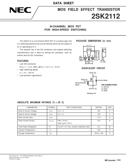
Document No. D11232EJ2V0DS00 (2nd edition)Date Published June 1996 PPrinted in Japan199622SK21123TYPICAL CHARACTERISTICS (T A = 25 ˚C)DERATING FACTOR OF FORWARD BIAS SAFE OPERATING AREAd T - De r a t i n g F a c t o r - %FORWARD BIAS SAFE OPERATING AREAV DS - Drain to Source Voltage - VI D - D r a i n C u r r e n t - AV GS - Gate to Source Voltage - VFORWARD TRANSFER ADMITTANCE vs.DRAIN CURRENT I D - Drain Current - A |y f s | - F o r w a r d T r a n s f e r A d m i t t a n c e - SDRAIN TO SOURCE ON-STATE RESISTANCE vs. DRAIN CURRENT I D - Drain Current - AR D - Ω4DRAIN TO SOURCE ON-STATE RESISTANCE vs. DRAIN CURRENTI D - Drain Current - A SWITCHING CHARACTERISTICSI D - Drain Current - At d (o n ), t r , t d (o f f ), t f - S w i t c h i n g T i m e - n sDRAIN TO SOURCE ON-STATE RESISTANCE vs. GATE TO SOURCE VOLTAGE 10.5051020V GS - Gate to Source Voltage - VR D S (o n ) - D r a i n t o S o u r c e O n -S t a t e R e s i s t a n c e - ΩI D = 0.5 A15C i s s , C o s s , C r s s - C a p a c i t a n c e - p FCAPACITANCE vs.DRAIN TO SOURCE VOLTAGEV DS - Drain to Source Voltage - V I S D - D i o d e F o r w a r d C u r r e n t - ASOURCE TO DRAIN DIODEFORWARD VOLTGE10.010.20.40.71V SD - Source to Drain Voltage - V0.80.90.30.50.60.10.0010.0001R D S (o n ) - D r a i n t o S o u r c e O n -S t a t e R e s i s t a n c e - ΩREFERENCEDocument Name Document No.NEC semiconductor device reliability/quality control system TEI-1202Quality grade on NEC semiconductor devices IEI-1209 Semiconductor device mounting technology manual C10535EGuide to quality assurance for semiconductor devices MEI-1202 Semiconductor selection guide X10679E5[MEMO]No part of this document may be copied or reproduced in any form or by any means without the prior written consent of NEC Corporation. NEC Corporation assumes no responsibility for any errors which may appear in this document.NEC Corporation does not assume any liability for infringement of patents, copyrights or other intellectual property rights of third parties by or arising from use of a device described herein or any other liability arising from use of such device. No license, either express, implied or otherwise, is granted under any patents, copyrights or other intellectual property rights of NEC Corporation or others.While NEC Corporation has been making continuous effort to enhance the reliability of its semiconductor devices, the possibility of defects cannot be eliminated entirely. To minimize risks of damage or injury to persons or property arising from a defect in an NEC semiconductor device, customer must incorporate sufficient safety measures in its design, such as redundancy, fire-containment, and anti-failure features.NEC devices are classified into the following three quality grades:“Standard“, “Special“, and “Specific“. The Specific quality grade applies only to devices developed based ona customer designated “quality assurance program“ for a specific application. The recommended applicationsof a device depend on its quality grade, as indicated below. Customers must check the quality grade of each device before using it in a particular application.Standard:Computers, office equipment, communications equipment, test and measurement equipment, audio and visual equipment, home electronic appliances, machine tools, personal electronicequipment and industrial robotsSpecial:Transportation equipment (automobiles, trains, ships, etc.), traffic control systems, anti-disaster systems, anti-crime systems, safety equipment and medical equipment (not specifically designedfor life support)Specific:Aircrafts, aerospace equipment, submersible repeaters, nuclear reactor control systems, life support systems or medical equipment for life support, etc.The quality grade of NEC devices in “Standard“ unless otherwise specified in NEC's Data Sheets or Data Books.If customers intend to use NEC devices for applications other than those specified for Standard quality grade, they should contact NEC Sales Representative in advance.Anti-radioactive design is not implemented in this product.M4 94.11。
- 1、下载文档前请自行甄别文档内容的完整性,平台不提供额外的编辑、内容补充、找答案等附加服务。
- 2、"仅部分预览"的文档,不可在线预览部分如存在完整性等问题,可反馈申请退款(可完整预览的文档不适用该条件!)。
- 3、如文档侵犯您的权益,请联系客服反馈,我们会尽快为您处理(人工客服工作时间:9:00-18:30)。
TOSHIBA Diode Silicon Epitaxial Planar Type1SS272Ultra High Speed Switching Applicationz Small package : SC-61z Low forward voltage : V F (3) = 0.92V (typ.) z Fast reverse recovery time : t rr = 1.6ns (typ.)z Small total capacitance : C T = 0.9pF (typ.)Absolute Maximum Ratings (Ta = 25°C)Characteristic Symbol RatingUnitMaximum (peak) reverse voltage V RM 85 V Reverse voltageV R 80 V Maximum (peak) forward current I FM 300 (*) mA Average forward current I O 100 (*) mA Surge current (10ms) I FSM 2 (*) A Power dissipation P 150 mW Junction temperature T j 125 °C Storage temperature rangeT stg−55~125°CNote: Using continuously under heavy loads (e.g. the application of high temperature/current/voltage and the significant change in temperature, etc.) may cause this product to decrease in thereliability significantly even if the operating conditions (i.e. operatingtemperature/current/voltage, etc.) are within the absolute maximum ratings.Please design the appropriate reliability upon reviewing the Toshiba Semiconductor Reliability Handbook (“Handling Precautions”/“Derating Concept and Methods”) and individual reliability data (i.e. reliability test report and estimated failure rate, etc). (*) Unit rating. Total rating = Unit rating × 1.5.Electrical Characteristics (Ta = 25°C)Characteristic SymbolTestCircuitTest ConditionMinTyp.MaxUnitV F (1)― I F = 1mA ― 0.61 ― V F (2) ― I F = 10mA ― 0.74 ― Forward voltageV F (3)― I F = 100mA ― 0.92 1.20VI R (1) ― V R = 30V ― ― 0.1Reverse current I R (2) ― V R = 80V ―― 0.5μATotal capacitance C T ― V R = 0, f = 1MH z ― 0.9 2.0 pF Reverse recovery timet rr―I F = 10mA ,Fig.1― 1.6 4.0 nsMarkingJEDEC ― EIAJ SC −61 TOSHIBA 2−3J1A Weight: 0.013gUnit: mmFig.1 Reverse recovery time (t rr ) test circuitRESTRICTIONS ON PRODUCT USE20070701-EN GENERAL •The information contained herein is subject to change without notice.•TOSHIBA is continually working to improve the quality and reliability of its products. Nevertheless, semiconductor devices in general can malfunction or fail due to their inherent electrical sensitivity and vulnerability to physical stress. It is the responsibility of the buyer, when utilizing TOSHIBA products, to comply with the standards of safety in making a safe design for the entire system, and to avoid situations in which a malfunction or failure of such TOSHIBA products could cause loss of human life, bodily injury or damage to property.In developing your designs, please ensure that TOSHIBA products are used within specified operating ranges as set forth in the most recent TOSHIBA products specifications. Also, please keep in mind the precautions and conditions set forth in the “Handling Guide for Semiconductor Devices,” or “TOSHIBA Semiconductor Reliability Handbook” etc.• The TOSHIBA products listed in this document are intended for usage in general electronics applications (computer, personal equipment, office equipment, measuring equipment, industrial robotics, domestic appliances, etc.).These TOSHIBA products are neither intended nor warranted for usage in equipment that requires extraordinarily high quality and/or reliability or a malfunction or failure of which may cause loss of human life or bodily injury (“Unintended Usage”). Unintended Usage include atomic energy control instruments, airplane or spaceship instruments, transportation instruments, traffic signal instruments, combustion control instruments, medical instruments, all types of safety devices, etc.. Unintended Usage of TOSHIBA products listed in his document shall be made at the customer’s own risk.•The products described in this document shall not be used or embedded to any downstream products of which manufacture, use and/or sale are prohibited under any applicable laws and regulations.• The information contained herein is presented only as a guide for the applications of our products. No responsibility is assumed by TOSHIBA for any infringements of patents or other rights of the third parties which may result from its use. No license is granted by implication or otherwise under any patents or other rights of TOSHIBA or the third parties.• Please contact your sales representative for product-by-product details in this document regarding RoHS compatibility. Please use these products in this document in compliance with all applicable laws and regulations that regulate the inclusion or use of controlled substances. Toshiba assumes no liability for damage or losses occurring as a result of noncompliance with applicable laws and regulations.。
