IPI60R250CP中文资料
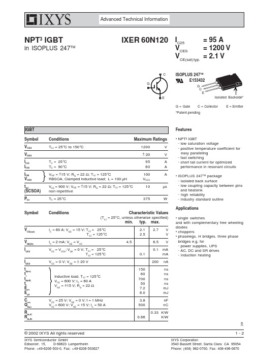
IXER60N120中文资料
Advanced Technical Information
NPT3 IGBT
in ISOPLUS 247TM
IXER 60N120 IC25
VCES VCE(sat) typ.
C G
= 95 A = 1200 V = 2.1 V
ISOPLUS 247TM E153432
IXYS Semiconductor GmbH Edisonstr. 15, D-68623 Lampertheim Phone: +49-6206-503-0, Fax: +49-6206-503627
1-2
IXYS Corporation 3540 Bassett Street, Santa Clara CA 95054 Phone: (408) 982-0700, Fax: 408-496-0670
© 2002 IXYS All rights reserved
2-2
• single switches and with complementary free wheeling diodes • choppers • phaselegs, H bridges, three phase bridges e.g. for - power supplies, UPS - AC, DC and SR drives - induction heating
VCE(sat) VGE(th) ICES IGES td(on) tr td(off) tf Eon Eoff Cies QGon RthJC RthJH
IC = 60 A; VGE = 15 V; TVJ = 25°C TVJ = 125°C IC = 2 mA; VGE = VCE VCE = VCES; VGE = 0 V; TVJ = 25°C TVJ = 125°C VCE = 0 V; VGE = ± 20 V
IP视频PoE60W系列产品说明书

-Wire IP Video Fiber Optics SFP er Optics Media ConvertersPoE Repeaters 4K Ult Surge Protecto D DAs 60W PoE MiFiber Optics SFPs ax IP VideoFiber Optics Media Converters Analog Video over UTP HD Video & P HD-CVI over UTP HD DAsHD Video &Power Supplies60W PoE Midspans2-Wire IP Video Fiber Optics SFPsCoax IP Video Fiber Optics Media ConvertersPoE RepeatersPoE Splitters4K Ultra HD ComplientSurge ProtectorsAnalog Video over UTPHD Video & PoUHD-TVI over UTPPower Supplies HD-CVI over UTPansSymmetric Bandwidth (SBW™)Maintains maximum bandwidth throughout speci ed distances for both upload and downloads.Virtual Zero Packet Loss (VZPL™)In network communication, information is transferred in Packets. Loss of Packets equals loss of information. Tested to RFC 2544 TCP/IP for packets sizes up to 9,000 bytes Jumbo Frames.Pass-Through-PoE (PTP™)Passes through the PoE power without interfering in the PSE-PD communication.Extended Pass-Through-PoE (EPTP™)The ability to pass 802.3af/at and PoE ++ up to 74W transmitting power at extreme distances with minimal power losses.Hardened (HRD™)Vigitron products are type tested for operation from -40°C to + 75°C under tough NEMA-TS2 transportation testing standards.Low Power Consumption (LPC™)The industry’s lowest power consumption, reserving needed power for PoE devices, and saving installation and operating costs.Mega Pixel Certi ed (MPC™)Testing is done to manufacturers’ high-end Megapixel cameras. Vigitron products have also been tested by several IP camera manufacturers, resulting in their strong endorsements.RFC Certi edVigitron products are tested under RFC 2544 speci cations for Packet loss, Bandwidth and Latency and the highest Jumbo frame size of 9,000 bytes, which provides the ability to transmit the largest megapixel size cameras with virtually no loss.RFCC ™LPC ™HRD ™-40C+75CSupport Jumbo Frames (JFC ™)Jumbo Frame compatibility assures reliable full bandwidth transmission of the highest megapixel cameras with maintaining image quality at high frame rates.Vigitron products are tested up to the full jumbo frame rate of 9000 bytes.60W PoEVigitron PoE++ products transmit up to 74W power at extended distances to cameras with PTZ, IR Illuminators, heaters and blowers, eliminating the need for any local power supplies and power outlets.Vigitron AdvantagesPoE++60WOur most important products are free!L i f e t i m e W a r r a n t y L i f e t i me W a r r a n t y L if et i m e W a r r a n ty Vigitron vs. CompetitionFeature Vigitron CompetitorsComplete IP Infrastructure ProviderX Free Design ServicesX Performance Backed by Certi ed TestingX Highest BandwidthX Highest PoE Power CapacityX Real World Product TestingX IP Camera Interoperability TestingX Products Made in USAX Industry’s Longest WarrantyX Vigitron’s Lifetime WarrantyVigitron, with about 2 decades of design and manufacturing experience, provides the most reliable products supported by the industry's longest warranty. Our warranty is the production lifetime plus three years to assure you of continued support, even after a product's end of life. Design Services and Extended W arranty are two of V igitron's most important and free products.MaxiiNet™ High Power Managed PoE SwitchesVi3026 PoE Switch Data + PowerPoE CamerasNVRExtended distance CoaxVi2401AVi2401AData + PowerData + PowerExtended distance CoaxVi2301AVi2301AThe Vi3010 is a high power PoE switch that provides 10 Gb ports and 2 SFP sockets for fiber Vi3010 PoE Switch Master ControlBuilding#2Building#1Building#3Data + PowerPoE CamerasNVRExtended distance CoaxVi2401AVi2401AData + PowerData + PowerData + PowerExtended distance CoaxVi2301AVi2301AVi3026/Vi3326Vi3026Vi3010Vi3010Model FunctionVi31055-Port 60W PoE Powered PoE Switch w/ UTP and Fiber Uplink Vi300560W60W Vi32055-Port 60W PoE Powered PoE Switch W/ Extended UTP Uplink 5-Port PoE Powered PoE Switch W/ Extended Coax UplinkApplication DiagramsVi2216ANVRVi3326Network SwitchMaxiiNet Vi3005™5-port PoE Powered PoE Switch328 ft. (100m) Cat-5Data + 60W PoE328 ft. (100m) Cat-5, Data + PoEVi3005PoE Cameras60WNVRData + 60W PoE328 ft. (100m) Cat-5, Data + PoEVi3105PoE CamerasVi2316AVi2216ANVRExtended Coax up to 3,000 ft. (914 m)Data + 30W PoE328 ft. (100m) Cat-5, Data + PoEVi3205PoE CamerasVi2416ANVRThe Vi3005 is a Layer 2 PoE switch that can be powered by PoE or local power supply. It The Vi3105 is a layer 2 PoE switch that can be powered by PoE or local power supply and The Vi3205 is a layer 2 PoE switch that can be powered by PoE or local power supply and Vi3326Network SwitchVi3026PoE SwitchMaxiiNet ™ Hardened PoE Powered PoE SwitchModel FunctionMaxiiCopper ™ Ethernet Extenders over CoaxSingle port 10/100 Ethernet Extender w/ Pass-Through-PoE • Extends 10BaseT up to 5,000 ft. (1,524m)• Extends 100BaseT up to 1,800 ft. (548m)• Provides Pass-Through-PoE up to 30W • Provides automatic Bandwidth detectionVi2401A Vi2404A Vi2408A 4-port 10/100 Ethernet Extenderw/ Pass-Through-PoE 8-port 10/100 Ethernet Extenderw/ Pass-Through-PoE Vi2416A16-port 10/100 Ethernet Extenderw/ Pass-Through-PoEMini Ethernet Extender w/ Pass-Through-PoE Vi2400A Data & PoE Range*Vi3026 PoE SwitchPoE CamerasNVRExtended distance CoaxVi2401AVi2400AVi3026 PoE SwitchData + PowerPoE CamerasNVRExtended distance CoaxVi2401AVi2401AJunction BoxThe Vi2401A is the perfect solution for analog systems transitioning to IP . It reduces the installation cost by maintaining existing coax wiring. Pass-Through-PoE eliminates the need for local power supplies for the extender and IP camera at the remote site.Vi2416APoE CamerasNVRExtended distance Coax, Data + PoEExtended distance Coax, Data + PoEUp to 328 ft. (100m) Cat-5Data + PoEVi2401AVi2401AMulti Port MaxiiCopper ™ over Extended CoaxVi2216ANetwork Switch The Vi24xxA series Pass-Through-PoE eliminate the need for local power supplies for the extender and IP camera at the remote site.Vi2416APoE CamerasNVRExtended distance Coax, Data + PoEExtended distance Coax, Data + PoEUp to 328 ft. (100m) Cat-5Data + PoEVi2401AVi2401AMulti Port MaxiiCopper ™ over Extended CoaxVi3026 PoE Switch The Vi24xx series are capable of running data and PoE power over single pair twisted or Up to 328 ft. (100m) Cat-5PoE CamerasVi2416AVi2401AVi0030Vi0030Vi2216ANVRNetwork SwitchVi2401A• Extends 10BaseT up to 3,000 ft. (914m)MaxiiCopper ™ Ethernet Extenders over UTPVi3026 PoE SwitchPoE CamerasNVRExtended distance UTPVi2301AVi2301AThe Vi2301A can transmit power sources up to 74 W providing the power for PoE PTZ dome PoE CamerasVi2301AVi2301AVi2301ANVRNetwork Switch60W PoE CameraVi2216 MidspamJunction BoxVi2300AExtended distance UTPUp to 328 ft. (100m) Cat-5PoE CamerasVi2316AVi2301AVi2216ANVRNetwork Switch Vi2301AThe Vi2701RX and Vi2301A combination provides a single channel extended distance high Extended distance Cat-5, Data + PoEExtended distance Cat-5, Data + PoEVi2301ANVRNetwork SwitchVi2301AVi2301AVi2701TXVi2216APoE Camera60W NVRNetwork SwitchPoE CameraPoE CameraVi2301AVi2301ANVRNetwork Switch The Vi2701 is not only an extended distance data and 60W PoE solution, but it is also an Vi2701TXPoE CamerasVi2701RXVi2701RXVi1120Vi1120Vi1120Vi310560NVRNetwork Switch60W PoE Camera60W PoE CameraVi2300WVi2300Vi2701RXVi2701RXVi1120Vi1120MaxiiNet ™ Hardened PoE Powered PoE SwitchNVRVi3405PoE CamerasNVRVi3305PoE CamerasExtended Coax up to 3,000 ft. (914 m)Vi1120Vi1120Vi3326Network Switch328 ft. (100m)Vi3326Network Switch328 ft. (100m)Vi2300A60W PoE CameraData + 30W PoE Vi0015Vi2301A Vi2301ANVRVi3305Vi1120Vi3326Network Switch328 ft. (100m)IP PhoneVi2300AVi2400AVi2301AWiFi RouterMaxiiPower ™ High Power PoE MidspansPoE CamerasData + PoEData + PoEExtended distance CoaxExtended distance CoaxVi2401ANetwork SwitchNVRVi2401AVi2301AVi2301AVi2216ANetwork Switch NVRVi2202Vi2202PoE CameraPoE Camera PoE CameraVi112060WPoE CameraMaxiiPower ™Single port PSENetwork Switch NVRVi220130W PoE CameraDataDataMaxiiPower ™ High Power Extended Coax PoE MidspansVi2616PoE CamerasNetwork SwitchNVRExtended distance Coax, Data + PoEExtended distance Coax, Data + PoEData + PoEVi2401AVi2401AThe Vi24xx series are capable of running data and PoE power over single pair twisted or Up to 328 ft. (100m) Cat-5PoE CamerasVi2416Vi2401Vi2401Vi0030Vi0030Vi2216NVRNetwork SwitchNVR Network SwitchPoE Camera60W Vi2516Vi2701TXVi2301AUp to 328 ft. (100m) Cat-5NVR Network SwitchPoE Camera60W Vi2516Vi2701TXVi2701TX Up to 328 ft. (100m) Cat-5The above solution is ideal for PoE applications requiring power greater than 802.3at (30W) i2301A provides Pass-Through-PoE (PTP™) without the need for local power sources. It is Vi2516PoE CamerasNVRNetwork SwitchUp to 328 ft. (100m) Cat-5Vi2301AVi3105MaxiiPower ™PoE SplitterNetwork Switch NVRVi2201DatalightIRVi22201Data MaxiiPower ™PoE SplitterNetwork Switch NVRVi2201DataNon-PoE CameraVi22101Data Extended distance CoaxExtended distance UTPVi2401A Network SwitchNVRVi2401AVi2301A Vi2301AVi2216AVi22201Vi22201Data DataEmergency SystemsWiFi RouterNVR328 ft. (100m) Cat-5Data + PoEPoE CamerasVi2216ANVRVi3003 3-port Drop & Insert 60W PoE SwitchDataData + 60W PoE Vi3003Vi3003Vi3003328 ft. (100m) Cat-5Data + 30W PoEVi3103Vi3103Data 60W PoEPoE Cameras328 ft. (100m) Cat-5The Vi3003 enables 1G connection between network switches eliminating the need for PoE CamerasVi3103328 ft. (100m) Cat-5328 ft. (100m) Cat-5328 ft. (100m) Cat-5Vi300360W PoE PTZ Camera328 ft. (100m) Cat-5, Data328 ft. (100m) Cat-5Data + 60W PoE NVRVi3326 Network SwitchVi3003Vi1120328 ft. (100m) Cat-5Data + 30W PoEThe Vi3103 is both a repeater and L2 3-port network switch providing drop and insert The Vi3003 is both a repeater and L2 3-port network switch providing drop and insert capability. Vi3003 allows for transmission of two cameras over a single cable or adding a new camera Vi3326 Network SwitchVi3026 PoE Switch328 ft. (100m) Cat-5IRPoE Camera328 ft. (100m) 1000BaseT328 ft. (100m) 1000BaseTVi0012Vi3003Network SwitchNetwork SwitchNetwork SwitchVi0025Vi2216ANVRNetwork SwitchPoE CameraPoE CameraVi3002W #8Vi3002WVi3002W #2Vi3002W #1NVRNetwork Switch Vi2216APoE Camera60W NVRNetwork Switch Vi2216A PoE Camera30W Up to 328 ft. (100m) Cat-5Vi3002Up to 328 ft. (100m) Cat-5Up to 328 ft. (100m) Cat-5Up to 328 ft. (100m) Cat-5Data + 60W PoEUp to 328 ft. (100m) Cat-5Vi3002Vi3002Vi3002Vi3002The Vi3002W complies with IP67 standards eliminating extra housing costs. Its unique enclosureNVRNetwork Switch PoE Camera60W Vi2516AVi2701TXVi2701TXUp to 328 ft. (100m) Cat-5MaxiiCopper ™ 60W PoE and Ethernet ExtendersNVRNetwork Switch PoE Camera60W Vi2701RXVi2701RXVi2701TXVi2701TXi2804AP combination can power up to 4 remote cameras by providing 74W NVRNetwork SwitchPoE CamerasVi1120Vi1120Vi1120Vi1120Vi1120Vi2701RXVi2301AVi3105Vi2701RXVi2701RXNetwork Switch NVRVi2202PoE Camera60W PoE CameraVi1120PoE AccessoriesNetwork SwitchNVRVi001560W PoE Camera328 ft. (100m) 1000BaseT328 ft. (100m) 1000BaseTVi0012Vi3003Network SwitchNetwork SwitchNetwork SwitchVi0025Vi2216ADataVi2216 PoE MidspanNetwork SwitchNVRViewMate™ Data + PowerData + PowerPoE CameraPoE CameraExtended Distance UTPStandard Distance UTPIP Camera Test ToolsVi0021Vi0019MaxiiFiber ™ Fiber Optics Transmision EquipmentNVRNetwork SwitchPoE CameraVi5001Vi0017NVRNetwork SwitchPoE CameraVi5001 + SFPVi0017Vi5001 + SFPVi0017NVRNetwork SwitchVi5004328 ft. (100m) Cat-5Vi0017Vi5001PoE CamerasVi51000Vi0012The Vi51004 is a 4-port Media converter receiver. It works in conjunction with Vi51000 Fiber HD DVRVi51001HD CameraVi0017HD DVRVi51004Vi51000HD CamerasVi0012HD CameraVi61001MVi10004HD CamerasVi10004i1004 can transmit 4 HD videos on a single Cat5/6 cable to save installation time and cost.4 x HD Video over Cat5/6CoaxVi10001MVi10016HD DVRHD CamerasVi10001FVi10001MVi10001PHD DVRHD DVRVi10001MHD DVRHD CamerasHD DVRHD Cameras Vi10001MVi61000Vi61000Vi61001HD DVRHD CameraVi15001Vi15000HD DVRVi15016Vi15000Hd Video + 12VDCHD CameraHd Video + 12VDCApplication DiagramsHD DVRHD CamerasHD Cameras Vi16004Vi16002HD DVR Vi18016Vi18000HD CameraHd Video + 12VDCHD Video & Power over CoaxVi18000HD CameraHd Video + 12VDC Vi18001*Available November 2015Video SolutionsPassive TransceiversModel Surge Protection*VB1001FVB1001MVB1001PVB1007MTransmittersVideo, Power & Data Solutions。
Infineon-IPW60R125P6-DS-v02_00-en
MetalOxideSemiconductorFieldEffectTransistor
CoolMOS™P6
600VCoolMOS™P6PowerTransistor IPx60R125P6
DataSheet
Rev.2.0 Final
PowerManagement&Multimarket
Gate Pin 1
Source Pin 3
Table1KeyPerformanceParameters
Parameter
Value
Unit
VDS @ Tj,max
650
V
RDS(on),max
125
mΩ
Qg.typ
56
nC
ID,pulse
87
A
Eoss@400V
7.2
µJ
Body diode di/dt
Reverse diode dv/dt 3)
ID ID,pulse EAS EAR IAR dv/dt VGS VGS Ptot
Ptot Tstg Tj -
IS IS,pulse dv/dt
Maximum diode commutation speed
Insulation withstand voltage for TO-220FP
-
-
2500 V Vrms,TC=25°C,t=1min
1) Limited by Tj max. Maximum duty cycle D=0.75 2) Pulse width tp limited by Tj,max 3)IdenticallowsideandhighsideswitchwithidenticalRG
CP Microwave Oven 60hz Compact Models 技术手册说明书

ServiceCommercial Microwave Oven60hz Compact Modelsstarting at Serial No. 1910000000 Service ManualThis Base Manual covers all Commercial Microwave Ovens. Refer to individual Technical Sheet for information on a specific model.This manual is to be used by qualifiedservice technicians only. ACP, Inc.does not assume any responsibility forproperty damage or personal injury forimproper service procedures done byan unqualified person.164000441TABLE OF CONTENTSImportant Safety Instructions ............................................................................................. 3-4 Oven Specifications .......................................................................................................... 5-6 Quick Start Reference Guide ............................................................................................. 7-8 Component Location ........................................................................................................ 9-13 Airflow .. (14)Component Testing ....................................................................................................... 15-17 Service Mode. (17)Power Output Test (18)Wiring and Schematic Diagrams.................................................................................... 19-222IMPORTANT SAFETY INSTRUCTIONSImportant Safety Information. Read before using this oven.Keep these instructions for future reference.If the oven changes ownership, be sure this guide accompanies oven. For additional product documentation or more detailed operating instructions visit:CONTACT INFORMATIONAny questions or to locate an authorized ACP servicer, call ACP ComServ Service Support.–Inside the U.S.A. or Canada, call toll-free 866-426-2621.–Outside the U.S.A. and Canada, call 319-368-8120.–Email: **********************************.Warranty service must be performed by an authorized ACP servicer. ACP also recommends contacting an authorized ACP servicer, or ACP ComServ Service Support if service is required after warranty expires.PRECAUTIONS TO AVOID POSSIBLE EXPOSURE TO EXCESSIVE MICROW A VE ENERGYA. DO NOT attempt to operate this oven with the door open since open door operation can resultin harmful exposure to microwave energy.It is important not to defeat or tamper with the safety interlocks.B. DO NOT place any object between the oven front face and the door or allow soil or cleanerresidue to accumulate on sealing surfaces.C. DO NOT operate the oven if it is damaged. It is particularly important that the oven door closeproperly and that there is no damage to the:1. door (bent)2. hinges and latches (broken or loosened)3. door seals and sealing surfaces.D. The oven should not be adjusted or repaired by anyone except properly qualified servicepersonnel.3To avoid risk of personal injury or property damage, observe the following safety CAUTIONinstructions:General Use:1. Do not use regular cooking thermometers in oven. Most cooking thermometers contain mercury and maycause an electrical arc, malfunction, or damage to oven.2. Never use paper, plastic, or other combustible materials that are not intended for cooking.3. When cooking with paper, plastic, or other combustible materials, follow manufacturer’s recommendationson product use.4. Do not use paper towels which contain nylon or other synthetic fibers. Heated synthetics could melt andcause paper to ignite.5. To avoid surface deterioration, keep the oven in a clean condition. Infrequent cleaning could adverselyaffect the life of the appliance and possible result in a hazardous situation.6. Clean oven regularly and remove any food deposits.Heating Foods and Liquids:7. Liquids such as water, coffee, or tea are able to be overheated beyond the boiling point without appearing tobe boiling due to surface tension of the liquid. Visible bubbling or boiling when the container is removed from the microwave oven is not always present. THIS COULD RESULT IN VERY HOT LIQUIDSSUDDENLY BOILING OVER WHEN A SPOON OR OTHER UTENSIL IS INSERTED INTO THE LIQUID.To reduce the risk of injury to persons:•Do not overheat the liquid.•Stir the liquid both before and halfway through heating it.•Do not use straight-sided containers with narrow necks.•After heating, allow the container to stand in the microwave for a short time before removing it.b. Use extreme care when inserting a spoon or other utensil into the container.8. Do not deep fat fry in oven. Fat could overheat and be hazardous to handle.9. Do not cook or reheat eggs in shell or with an unbroken yolk using microwave energy.Pressure may buildup and erupt. Pierce yolk with fork or knife before cooking.10. Pierce skin of potatoes, tomatoes, and similar foods before cooking with microwave energy.When skin ispierced, steam escapes evenly.11. Do not heat sealed containers or plastic bags in oven. Food or liquid could expand quickly and causecontainer or bag to break. Pierce or open container or bag before heating12. Do not heat baby bottles in oven.13. Baby food jars shall be open when heated and contents stirred or shaken before consumption, in orderto avoid burns.14. Never use oven to heat alcohol or food containing alcohol as it can more easily catch fire ifoverheated.Additional Microwave Oven Safety Instructions:15. Do not operate equipment without load or food in oven cavity.16. Use only popcorn in packages designed and labeled for microwave use. Popping time variesdepending on oven wattage. Do not continue to heat after popping has stopped. Popcorn will scorch or burn. Do not leave oven unattended.17. Do not use metal utensils in oven.18. An authorized servicer MUST inspect equipment annually. Record all inspections and repairs for futureuse.45InstallationUnpacking Oven∙Inspect oven for damage such as dents in door or dents inside oven cavity.∙Report any dents or breakage to source of purchase immediately. Do not attempt to use oven if damaged.∙Remove all materials from oven interior.∙If oven has been stored in extremely cold area, wait a few hours before connecting power.Radio InterferenceMicrowave operation may cause interference to radio, television, or similar. Reduce or eliminate interference by doing the following: Clean door and sealing surfaces of oven according to instructions in “Care and Cleaning” section.Place radio, television, wireless routers, etc. as far away as possible from oven.Use a properly installed antenna on radio, television, etc. to obtain a stronger signal reception.6QUICK START GUIDERefer to Owner’s Manual for Safety Statements. Complete Owner’s Manual available online.(C)(i) (ii) ( iii) (iv) (v) (vi)OVEN CLEARANCESA. Allow at least 2” (5.1 cm) of clearancearound top of oven. Proper airflow around oven cools electricalcomponents. With restricted air flow,oven may not operate properly and lifeof electrical parts is reduced.B. General market models: There is notan installation clearance requirementfor the back of the oven.HDC21RB2, MCHDC21, HDC21DQonly: Allow at least 1” (2.54 cm) ofclearance around back of oven.C. Allow at least 1” (2.54 cm) of clearance CONTROL PANEL FEATURES(A) USB Port(B) Display(C) Number Keypads(D) Start/ OK Keypad(E) Stop/ Reset Keypad(F) Secondary Function KeypadsTo activate, press and hold correspondingnumber keypad.(i) Manual Time Entry Mode (keypad “1”)(ii) Power Level (keypad “2”)(iii) Programming Mode (keypad “3”)(iv) User Options (number keypad “4”)(v) X2 - Double Quantity Cooking (keypad “5”)(vi) Menu A/B (keypad “6”)around sides of oven.D. Install oven so oven bottom is at least3 feet (91.5 cm) above floor. Preset Program Keypads To cook food using preprogrammed cookingsequences:1. Open oven door, place food in oven,and close oven door.2. Press desired number keypad(s).3. Oven operates and time counts down.4. At the end of the cooking cycle, theoven beeps. Carefully remove foodfrom oven.X2 - DOUBLE QUANTITY COOKING 1. Press and hold number keypad “5”/ X2to toggle double quantity feature ON.“X2” appears at top center of screenwhen enabled.2. Press desired number keypad(s).Display counts down cooking time fortwo quantities.MENU A/B (select models)Press and hold number keypad “6” to toggle between A and B menus. So…how do I use it?Manual Time Entry ModeTime entry mode allows the user to manually enter cook time and power level, without changing the preset program keypads.1. Open oven door, place food in oven, and close door.2. Press and hold number keypad “1”/ TIME ENTRY.3. Press number keypads to enter desired cook time.4. Press and hold number keypad “2”/ POWER LEVEL to change power level.•Press number keypads to ente r % microwave power (“1”=10%, “2”=20%,etc.) For 100% power level, press and hold number keypad “2”/ POWER LEVEL.5. Press START/OK keypad to begin cooking.6. At the end of the cooking cycle, the oven beeps. Carefully remove food from oven.Programming Mode1. Pre ss and hold number keypad “3”/ PROGRAM.2. Press number keypad(s) to open the desired program location.3. To edit name: Press number keypad “0”. Press number keypads to enter recipe name.Press START/OK keypad.4. To edit cook time for Stage One: Press number keyp ad “1”. Press number keypads toenter cook time. Press START/OK keypad.5. To edit power level for Stage One: Press number keypad “5”. Press number keypads toenter % microwave power (“1”=10%, “2”=20%,etc.). For 100% power level, press and hold number keypad “2”/ POWER LEVEL.6. If stage cooking is desired, repeat steps 4-5 for each additional stage, substitutingcorresponding number keypads for each stage.7. To save and exit programming mode: Press START/OK keypad.(A) (B) (F) (D) (E)This document covers HDC*, MDC*, DEC*, MCHDC*, and CRC* modelsAC BD7Access and Modify User OptionsThere are several options you can change to customize the operation of theoven for your business. Options are shown below. The factory setting isshown in bold type.1. Press and hold keypad number “4”/ USER OPTIONS.If prompted, enter the PIN Code and press START/OK keypad2. Press the START/OK keypad to scroll through pages of user options3. To access an individual user option, press the corresponding number keypad•To change the setting, press corresponding number keypad•To return to User Options Menu, press START or STOP/RESET4. Press STOP/RESET keypad to exit User Options MenuSTANDARD DEFAULT PER MODEL (FACTORY SETTINGS IN BOLD)Factory setting may vary by model* Available on select models only (only displayed in User Options menu if factory option is enabled)OVEN CONSTRUCTIONBLOWER, CAPACITOR, DIODE, INTERLOCKDOORCONTROL BOARD, MAGNETRONS, DUCTS, FUSETRAY, CAVITY, ANTENNASWRAPPER, ACCESS PANEL, LAMPAIR FLOW1.AIR ENTERS THROUGH FRONT FILTER2. AIR IS DRAWN INTO BLOWER3. AIR PUSHED THROUGH MAGNETRONS4. AIR PUSHED CAVITY AND EXITS THROUG CAVITY DUCTSCOMPONENT TESTINGretest.Blower Motor Remove all wires from motor.Measure resistance COM to 208Measure resistance COM to 230Measure resistance 208 to 230Approx 23ΩApprox 26ΩApprox 3ΩStirrer Motor- 25RPM Remove all wires from motor.Measure coil resistance Approximately 25k Ω.COM TransformerDischarge CapacitorRemove all wires from terminals, andmeasure resistance from:230 to Common………………………208 to Common………………………Terminal 5 to 6………………………..Terminal 7 to 8………………………Terminal 4 to Ground ………………….<1 Ω.<1 Ω.<1 Ω.<1Ω27Ω ±10%Interlock SwitchAssemblyDisconnect wires to switch.With door open measure resistancefrom:Primary – Terminals………….Monitor – Terminals………….Secondary – Terminals………With door closed measureresistance from:Primary –Terminals………….Monitor –Terminals………….Secondary – Terminals………Open/Infinite ΩClosed/ContinuityOpen/Infinite ΩClosed/ContinuityOpen/Infinite ΩClosed/ContinuityTouch Panel Assembly Disconnected from Main Board Pad Traces1 1 to 8 to 10 0-150Ω2 1 to 7 to 10 0-150Ω3 1 to 6 to 10 0-150Ω4 1 to5 to 10 0-150Ω5 1 to 4 to 10 0-150Ω6 1 to 3 to 10 0-150Ω7 1 to 8 to 9 0-150Ω8 1 to 7 to 9 0-150Ω9 1 to 6 to 9 0-150Ω0 1 to 5 to 9 0-150ΩStart 1 to 4 to 9 0-150ΩStop 1 to 4 to 8 0-150ΩSERVICE MODETO ACCESS THE SERVICE MODE:∙PRESS AND HOLD THE “7” PAD UNTIL THE PIN PROMPT IS DISPLAYED∙AT THE PIN PROMPT, ENTER 1,3,5,7 then 9 THEN SELECT FROM THE FOLLOWING:o 1 – USAGEThis shows Door Cycles, Tube Cycles, and Tube Hours.o 2 - ERROR HISTORYThis shows any Error Codes that have occurredo 3 - PIN CODEThis reveals the 4 digit PIN code required for programming (if enabled) o 4 - VOLTAGE SWITCHING (not available on 120vac units)Allows selection of Forced 208, Sensing (Auto Sense), or Forced 230 o 5 - EXPORT TO USBThis option requires a USB be inserted. Files that contain USAGE,OPTIONS & ENGINEERING SETTINGS, MENU PROGRAMMING, andERROR CODES will be downloaded.NOTE: Pressing the grey “stop” pad will navigate backwards.POWER OUTPUT TESTAll Amana and Menumaster microwave oven power outputs are rated using the IEC705standards. Using the IEC705 test method requires precision measurements and equipment that is not practical to be performed in the field. Using the test shown below will indicate if the oven performance is satisfactory.Test equipment required:∙1000 ml test container and thermometer (Amana power test kit Fahrenheit / Menumaster power test kit Celsius).∙Digital watch / watch with a second hand for use on ovens with electromechanical timers.Important Notes:∙Low line voltage will cause low temperature rise / power output.∙Ovens must be on a dedicated circuit, properly grounded, and polarized. Other equipment on the same circuit may cause a low temperature rise / power output.∙This test and results are not a true IEC705 test procedure and are only intended to provide servicers with an easy means of determining if the microwave oven cooking output is correct.Procedure1. Fill the test container to the 1000 ml line with cool tap water.NOTE:Water temperature should be approximately 60° F / 16° C.2. Using the thermometer, stir water for five to ten seconds; measure, and record the temperature (T1).3. Place test container of water in the center of oven cavity and close door.4. Heat the water for a 33-second full power cycle.NOTE:Use a digital watch or a watch with a second hand for ovens with electromechanical timers.1. At end of the cycle, remove test container. Using the thermometer, stir water for five to ten secondsand record temperature (T2).2. Subtract the starting water temperature (T1), from the ending water temperature (T2) to obtain thetemperature rise (∆T).3. If the temperature rise (∆T) meets or exceeds the minimum, the test is complete. If the temperaturerise (∆T) fails to meet the minimum temperature rise, test the line voltage to verify it is correct. Thenrepeat steps 1-6 making sure to change the water. If the temperature rise (∆T) fails to meet theminimum temperature rise again the oven will require service.OMPONENT TESTINGWIRING AND SCHEMATIC DIAGRAMSHDC12A2 P2007001MMDC12A2 P2007002MHDC182 P2007004M MDC182 P2007006M HDC1815 P2007003M HDC18SD2 P2007005M HDC212 P2007011M MDC212 P2007014M MDC182CA P2007008M MDC182CD P2007009M CRC18T2OG2 P2007010M HDC21RB2 P2007012M HDC21DQ P2007013M MCHDC21 P2007015M CRC21T2RLPF P2007016MMDC182SA P2007025M MDC212SA P2007031MMDC182K P2007007M。
IRFI260中文资料

Absolute Maximum RatingsParameterIRFI260Units I D @ V GS = 10V , T C = 25°C Continuous Drain Current 45*I D @ V GS = 10V , T C = 100°CContinuous Drain Current 29I DMPulsed Drain Current 180P D @ T C = 25°CMax. P ower Dissipation 300W Linear Derating Factor 2.4W/K V GS Gate-to-Source Voltage±20V E AS Single Pulse Avalanche Energy 700mJ I AR Avalanche Current45A E AR Repetitive Avalanche Energy 30mJ dv/dt Peak Diode Recovery dv/dt 4.3V/nsT J Operating Junction-55 to 150T STGStorage Temperature Range o CLead Temperature 300 (0.063 in. (1.6mm) from case for 10 sec.)Weight10.9 (typical)gN-CHANNELProvisional Data Sheet No. PD 9.809200 V olt, 0.060Ω, HEXFETAIRFI260HEXFET ® TRANSISTORHEXFET technology is the key to International Rectifier’s advanced line of power MOSFET transis-tors. The efficient geometry design achieves very low on-state resistance combined with high trans-conductance.HEXFET transistors also feature all of the well-es-tablished advantages of MOSFETs, such as voltage control, very fast switching, ease of paralleling and electrical parameter temperature stability. They are well-suited for applications such as switching power supplies, motor controls, inverters, choppers, audio amplifiers, high energy pulse circuits and virtually any application where high reliability is required.The HEXFET transistor’s totally isolated package eliminates the need for additional isolating material between the device and the heatsink. This improves thermal efficiency and reduces drain capacitance.Product SummaryPart Number BV DSS R DS(on)I D IRFI260200V0.060Ω45A*Features:n Hermetically Sealed n Electrically Isolatedn Simple Drive Requirements n Ease of Paralleling nCeramic Eyelets* I D current limited by pin diameterElectrical Characteristics @ Tj = 25°C (Unless Otherwise Specified)ParameterMin.Typ.Max.UnitsTest ConditionsBV DSSDrain-to-Source Breakdown Voltage200——VV GS = 0V , I D = 1.0 mA∆BV DSS /∆T J Temp. Coefficient of Breakdown Voltage —0.24—V/°C Reference to 25°C, I D = 1.0 mA R DS(on)Static Drain-to-Source——0.060V GS = 10V, I D =29AOn-State Resistance——0.068ΩV GS = 10V , I D = 45AV GS(th)Gate Threshold Voltage 2.0— 4.0V V DS = V GS , I D = 250µADSS µA DS GS ——250V DS = 0.8 x Max RatingV GS = 0V, T J = 125°CI GSS Gate-to-Source Leakage Forward ——100nAV GS = 20VI GSS Gate-to-Source Leakage Reverse ——-100V GS = -20V Q g Total Gate Charge——230V GS =10V , I D = 45A Q gs Gate-to-Source Charge——40nC V DS = Max. Rating x 0.5Q gd Gate-to-Drain (“Miller”) Charge ——110t d(on)Turn-On Delay Time ——29V DD = 100V , I D =45A,t rRise Time——120ns R G = 2.35Ω, V GS =10V t d(off)Turn-Off Delay Time ——110t f Fall T ime——92L DInternal Drain Inductance—8.7—L SInternal Source Inductance —8.7—nHC iss Input Capacitance —5100—V GS = 0V , V DS = 25VC oss Output Capacitance—1100—pFf = 1.0 MHzC rssReverse Transfer Capacitance —280—IRFI260 DeviceMeasured from the drain lead, 6mm (0.25in.) from package to center of die.Measured from the source lead, 6mm (0.25 in.) from package to source bonding pad.Modified MOSFET symbol showing the internal inductances.Thermal ResistanceParameterMin.Typ.Max.Units Test ConditionsR thJC Junction-to-Case ——0.42R thJA Junction-to-Ambient ——30 K/W typical socket mount R thCSCase-to-Sink—0.21—mounting surface flat, smoothSource-Drain Diode Ratings and CharacteristicsParameterMin.Typ.Max.UnitsTest ConditionsI S Continuous Source Current (Body Diode)——45*Modified MOSFET symbol showing the I SMPulse Source Current (Body Diode)——180Aintegral reverse p-n junction rectifier.V SD Diode Forward Voltage —— 1.8V T j = 25°C, I S = 45A, V GS = 0V t rr Reverse Recovery Time ——420ns T j = 25°C, I F = 45A, di/dt ≤ 100A/µsQ RR Reverse Recovery Charge —— 4.9µCV DD ≤ 50Vt onForward Turn-On TimeIntrinsic turn-on time is negligible. T urn-on speed is substantially controlled by L S + L D .IRFI260 DeviceCase Outline and Dimensions — T O-259AAWORLD HEADQUARTERS: 233 Kansas St., El Segundo, California 90245, Tel: (310) 322 3331EUROPEAN HEADQUARTERS: Hurst Green, Oxted, Surrey RH8 9BB, UK Tel: ++ 44 1883 732020IR CANADA: 7321 Victoria Park Ave., Suite 201, Markham, Ontario L3R 2Z8, Tel: (905) 475 1897IR GERMANY: Saalburgstrasse 157, 61350 Bad Homburg Tel: ++ 49 6172 96590IR ITALY: Via Liguria 49, 10071 Borgaro, Torino Tel: ++ 39 11 451 0111IR FAR EAST: K&H Bldg., 2F, 3-30-4 Nishi-Ikeburo 3-Chome, Toshima-Ki, Tokyo Japan 171 Tel: 81 3 3983 0086IR SOUTHEAST ASIA: 315 Outram Road, #10-02 Tan Boon Liat Building, Singapore 0316 Tel: 65 221 8371/Data and specifications subject to change without notice.7/96NOTES:1. Dimensioning and tolerancing per ANSI Y14.5M - 1982.2. All dimensions in millimeters (inches)CAUTIONBERYLLIA WARNING PER MIL-PRF-19500Packages containing beryllia shall not be ground, sandblasted,machined, or have other operations performed on them which will produce beryllia or beryllium dust. Furthermore, beryllium oxides packages shall not be placed in acids that will produce fumes containing beryllium.LEGEND:1. Drain 2.. Source 3. Gate。
IEC60255-5 translation中文版

IEC60255-5 译本Second editionTranslated by: Jiangping Chen电气继电器第五部分:测量继电器和保护设备的绝缘配合要求和测试Electrical relays—Part 5: Insulation coordination for measuring relays and protection equipment Requirement and tests电气继电器第五部分:测量继电器和保护设备的绝缘配合要求和测试IEC60255-51 范围和目的本标准适用于测量继电器和保护设备的绝缘配合一般要求。
注:本标准中除非特别说明,“测量继电器和保护设备”缩写为“继电器“。
本标准中,特别作说明的有以下几点:---术语的定义;---对于电气继电器的电气间隙、爬(漏)电距离与绝缘有关的其他方面的严酷等级的选择提供导则;---规定电压试验(包括冲击耐压试验)和绝缘电阻试验的要求。
本标准适用于额定电压交流至1000v,额定频率至65Hz或直流至1500v设备,其安装或使用于海拔高度至2000m。
本标准也适用于诸如分流器、串联电阻器、互感器等有关的辅助装置,这些装置与上述电气继电器一起使用并一起进行试验,若这些装置在相关的国际电工委员会出版物另有规定的除外。
注:对于海拔高度超过2000m装置的电气间隙参照表B.1。
2 引用标准下列标准所包含的条文,通过在本标准中引用而构成本标准的条文。
对于注日期的引用文件,其随后所有的修改单(不包括勘误的内容)或修订版均不适用于本标准,然而,鼓励根据本标准达成协议的各方研究是否可使用这些文件的最新版本。
凡是不注日期的引用文件,其最新版本适用于本标准。
国际标准化组织和国际电工委员会成员负责登记目前采用的国际标准有效性。
IEC 60050(151):1978, International Electro-technical Vocabulary (IEV) – Chapter 151: Electrical and magnetic devices IEC 60050(448):1995, International Electro-technical Vocabulary – Chapter 448: Power system protectionIEC 60060-1:1989, High-voltage test techniques – Part 1: General definitions and test requirementsIEC 60085:1984, Thermal evaluation and classification of electrical insulationIEC 60112:1979, Method for determining the comparative and the proof tracking indices of solid insulating materials under moist conditionsIEC 60255 (all parts), Electrical relaysIEC 60255-21-1:1988, Electrical relays – Part 21: Vibration, shock, bump and seismic tests on measuring relays and protection equipment – Section 1: Vibration tests (sinusoidal)IEC 60255-21-2:1988, Electrical relays – Part 21: Vibration, shock, bump and seismic tests on measuring relays and protection equipment – Section 2: Shock and bump testsIEC 60255-21-3:1993, Electrical relays – Part 21: Vibration, shock, bump and seismic tests on measuring relays and protection equipment – Section 3: Seismic testsIEC 60664-1:1992, Insulation coordination for equipment within low-voltage systems – Part 1:Principles, requirements and testsIEC 61000-4-5:1995, Electromagnetic compatibility (EMC) – Part 4: Testing and measurement techniques – Section 5: Surge immunity testIEC 61180-1:1992, High-voltage test techniques for low-voltage equipment – Part 1: Definitions and test procedure requirementsIEC 61180-2:1994, High-voltage test techniques for low-voltage equipment – Part 2: Test equipment3 定义本标准采用下列术语和定义,对于未规定的定义和术语应引用IEC 60050(448)、IEC 60664-1和IEC60255相关部分。
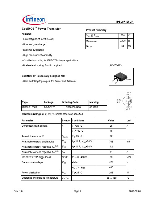
IPB60R125CP中文资料
IPB60R125CPMaximum ratings, at T j =25 °C, unless otherwise specified ParameterSymbol Conditions Unit Continuous diode forward current I S ADiode pulse current2)I S,pulse 82Reverse diode d v /d t 4)d v /d t15V/nsParameter Symbol ConditionsUnitmin.typ.max.Thermal characteristicsThermal resistance, junction - caseR thJC --0.6K/WR thJASMD version, device on PCB, minimal footprint--62SMD version, device on PCB, 6 cm 2cooling area 5)-35-Soldering temperature,wave- & reflowsoldering allowedT soldreflow MSL1--260°CElectrical characteristics, at T j =25 °C, unless otherwise specified Static characteristicsDrain-source breakdown voltage V (BR)DSS V GS =0 V, I D =250 µA 600--VGate threshold voltage V GS(th)V DS =V GS , I D =1.1 mA 2.53 3.5Zero gate voltage drain currentI DSSV DS =600 V, V GS =0 V, T j =25 °C--2µA V DS =600 V, V GS =0 V, T j =150 °C-20-Gate-source leakage current I GSS V GS =20 V, V DS =0 V --100nA Drain-source on-state resistanceR DS(on)V GS =10 V, I D =16 A, T j =25 °C-0.110.125ΩV GS =10 V, I D =16 A, T j =150 °C-0.30-Gate resistanceR Gf =1 MHz, open drain -2.1-ΩValues Thermal resistance, junction - ambientValue T C =25 °C16IPB60R125CPParameterSymbol ConditionsUnitmin.typ.max.Dynamic characteristics Input capacitance C iss -2500-pFOutput capacitanceC oss-120-Effective output capacitance, energyrelated 6)C o(er)-110-Effective output capacitance, timerelated 7)C o(tr)-300-Turn-on delay time t d(on)-15-ns Rise timet r -5-Turn-off delay time t d(off)-50-Fall timet f-5-Gate Charge Characteristics Gate to source charge Q gs -12-nCGate to drain charge Q gd -18-Gate charge total Q g -5370Gate plateau voltage V plateau -5.0-VReverse Diode Diode forward voltage V SD V GS =0 V, I F =16 A, T j =25 °C-0.9 1.2V Reverse recovery time t rr -430-ns Reverse recovery charge Q rr -9-µC Peak reverse recovery currentI rrm -42-A1)J-STD20 and JESD222)Pulse width t p limited by T j,maxValues V GS =0 V, V DS =100 V, f =1 MHzV DD =400 V,V GS =10 V, I D =16 A, R G =3.3 ΩV DD =400 V, I D =16 A, V GS =0 to 10 VV GS =0 V, V DS =0 V to 480 V4) I SD =I D , di/dt<=200A/µs, V DClink =400V, V peak <V (BR)DSS , T j <T jmax , identical low side and high side switch.V R =400 V, I F =I S , d i F /d t =100 A/µs6) C o(er) is a fixed capacitance that gives the same stored energy as C oss while V DS is rising from 0 to 80% V DSS.7)C o(tr) is a fixed capacitance that gives the same charging time as C oss while V DS is rising from 0 to 80% V DSS.3)Repetitive avalanche causes additional power losses that can be calculated as P AV =E AR *f.5)Device on 40mm*40mm*1.5 epoxy PCB FR4 with 6cm2 (one layer, 70µm thick) copper area for drain connection. PCB is vertical without blown air1 Power dissipation5 Typ. output characteristics9 Typ. gate charge13 Typ. capacitancesIPB60R125CP Definition of diode switching characteristicsIPB60R125CP PG-TO263-3-2/TO263-3-5/TO263-3-22: OutlinesDimensions in mm/inches:IPB60R125CPPublished byInfineon Technologies AG81726 München, Germany© Infineon Technologies AG 2006.All Rights Reserved.Attention please!The information given in this data sheet shall in no event be regarded as a guarantee of conditions ocharacteristics (“Beschaffenheitsgarantie”). With respect to any examples or hints given herein, any typicavalues stated herein and/or any information regarding the application of the device, Infineon Technologieshereby disclaims any and all warranties and liabilities of any kind, including without limitation warranties onon-infringement of intellectual property rights of any third partyInformationFor further information on technology, delivery terms and conditions and prices please contact your nearesInfineon Technologies Office ().WarningsDue to technical requirements components may contain dangerous substances. For information on the typesin question please contact your nearest Infineon Technologies Office.Infineon Technologies Components may only be used in life-support devices or systems with the expresswritten approval of Infineon Technologies, if a failure of such components can reasonably be expected tocause the failure of that life-support device or system, or to affect the safety or effectiveness of that device or system. Life support devices or systems are intended to be implanted in the human body, or to support and/or maintain and sustain and/or protect human life. If they fail, it is reasonable to assume that the health of theuser or other persons may be endangered.。
RI60中文资料
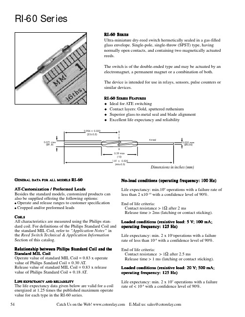
Catch Us on the Web! E-Mail us: sales@54RI-60 SeriesRI-60 S ERIESUltra-miniature dry-reed switch hermetically sealed in a gas-filled glass envelope. Single-pole, single-throw (SPST) type, having normally open contacts, and containing two magnetically actuated reeds.The switch is of the double-ended type and may be actuated by an electromagnet, a permanent magnet or a combination of both.The device is intended for use in relays, sensors, pulse counters or similar devices.RI-60 S ERIES F EA EATURES TURES u Ideal for ATE switchingu Contact layers: Gold, sputtered rutheniumu Superior glass-to-metal seal and blade alignment u Excellent life expectancy and reliabilityG ENERAL DATA FOR ALL MODELS RI-60A T -Customiza -Customization / Pr tion / Pr tion / Pref ef efor or ormed Leadsmed Leads Besides the standard models, customized products can also be supplied offering the following options:! Operate and release ranges to customer specification ! Cropped and/or preformed leadsC OILSAll characteristics are measured using the Philips stan-dard coil. For definitions of the Philips Standard Coil and the standard MIL Coil, refer to “Application Notes” in the Reed Switch Technical & Application Information Section of this catalog.Rela Relationship betw tionship betw tionship between Philips Standar een Philips Standar een Philips Standard Coil and the d Coil and the Standar Standard MIL Coild MIL Coil Operate value of standard MIL Coil = 0.83 x operate value of Philips Sandard Coil + 0.30 AT.Release value of standard MIL Coil = 0.83 x release value of Philips Standard Coil + 0.18 AT.L IFE EXPECT EXPECTANCYANCY AND RELIABILITY The life expectancy data given below are valid for a coil energized at 1.25 times the published maximum operate value for each type in the RI-60 series.No-load conditions (oper No-load conditions (opera a ting fr ting frequenc equenc equency:y:y: 100 Hz) 100 Hz)Life expectancy: min.109 operations with a failure rate of less than 2 x10⁻¹⁰ with a confidence level of 90%.End of life criteria:Contact resistance > 1Ω after 2 msRelease time > 2ms (latching or contact sticking).Loaded conditions (r Loaded conditions (resisti esisti esistiv v e load:e load: 55 5 V V ; 100 mA;oper opera a ting fr ting frequenc equenc equency:y:y: 125 Hz) 125 Hz)Life expectancy: min. 2 x 10⁷operations with a failure rate of less than 10-8 with a confidence level of 90%.End of life criteria:Contact resistance > 1Ω after 2.5 msRelease time > 1 ms (latching or contact sticking).Loaded conditions (r Loaded conditions (resisti esisti esistiv v e load:e load: 20 20 20 V V ; 500 mA;oper opera a ting fr ting frequenc equenc equency:y:y: 125 Hz) 125 Hz)Life expectancy: min. 2 x 10⁷ operations with a failure rate of < 10-8 with a confidence level of 90%.Dimensions in inches (mm)55Catch Us on the Web! E-Mail us: sales@ End of life criteria:Contact resistance > 2Ω after 2.5 msRelease time > 2.5 ms (latching or contact sticking).Switching different loads involves different life expect-ancy and reliability data. Further information is available on request.M ECHANICAL D A T AContact arrangement is normally open; lead finish is tinned; net mass is approximately 0.09 g; and can be mounted in any position.S HOCKThe switches are tested in accordance with “IEC 68-2-27”, test Ea (peak acceleration 100 G, half sinewave;duration 11 ms). Such a shock will not cause an open switch (no magnetic field present) to close.M ECHANICAL S TRENGTHThe robustness of the terminations is tested in accordance with “IEC 68-2-21”, test Ua 1 (load 10 N).O PERA PERATING TING AND S T ORA ORAGE GE T EMPERA EMPERATURETURE Operating ambient temperature; min: -55°C;max: +125°C.Storage temperature; min: -55°C; max: +125°C.Note:Note: Temperature excursions up to 150°C may be permissible. For more information contact your nearest Coto Technology sales office.S OLDERINGThe switch can withstand soldering heat in accordance with “IEC 68-2-20”, test Tb, method 1B: solder bath at 350 ±10° C for 3.5 ±0.5 s.Solderability is tested in accordance with “IEC 68-2-20”test Ta, method 3: solder globule temperature 235°C;ageing 1b: 4 hours steam.W ELDINGThe leads can be welded.M OUNTINGThe leads should not be bent closer than 1 mm to the glass-to-metal seals. Stress on the seals should be avoided. Care must be taken to prevent stray magnetic fields from influencing the operating and measuring conditions.RI-60 SeriesModel Number RI-60ParametersTest Conditions Units。
OMP60 & OMI-2_中文-1
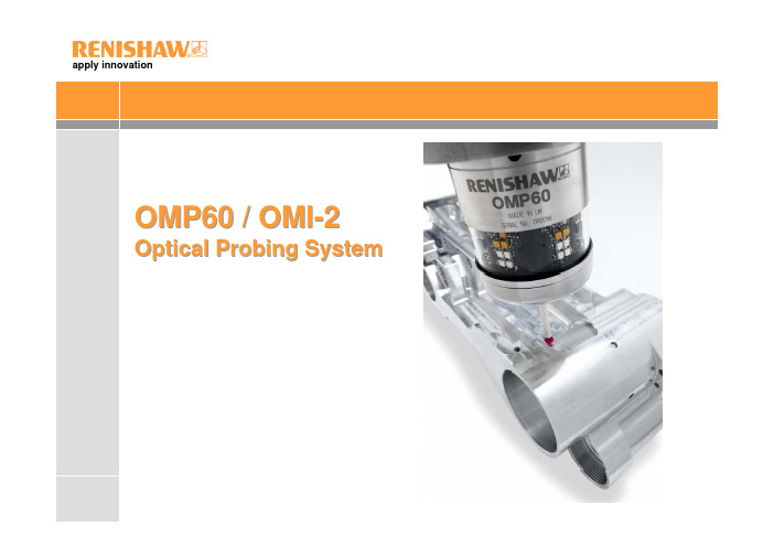
apply innovationOMP60 / OMI-2Optical Probing Systemapply innovationWhy has OMP60 been developed?Optical Machine Probe -OMP60OMP60 是Renishaw新一代工件量測測頭.OMP60的將是取代目前MP10 (M-code or auto-start), MP7 (spin-on/spin-off), MP9 (spin-on/timer-off) and MP8 (shank-switch-on/ shank-switch-off) 35°及70°各種不同的測頭.新的光學傳輸系統增加了阻絕光學干擾及從高頻電磁干擾的功能.這是必需與OMI-2(新的介面裝置)搭配使用.我們稱為Renishaw Coded Start/Modulated紅外線傳輸協定新產品的發展皆維持了與RENISHAW其他‘Legacy’光學系統(like the MP10)的協調性並可與目前的OMI,OMM和MI12搭配使用.OMP60 能夠使用於Legacy 或Modulated傳輸模式.“操作者可自行選擇傳輸模式”.apply innovationWhy has OMP60 been developed?其他所增加設計的考量:電池的更換方式更為容易.使用更容易取得的AA 電池.改善增加電池壽命.提供改善去抵抗衝擊及振動所產生的錯誤訊號.apply innovationWhat is OMP60?Optical Machine Probe -OMP60使用場所:中型或大型的CNC立式加速中心機或臥式加工中心機OMP60為不銹鋼及鋁合金的結構與RENISHAW 無線電測頭相同.OMP60尺寸為Ø63mm x 76mm(長) ,與RENISHAW其他的光學測頭比較,這是一個更緊實堅固的測頭.OMP60為360°紅外線光學傳輸系統並能夠結合35°和70°的差異於單一測頭上.可搭配的介面裝置:OMIOMM / MI12OMI-2OMP60 啟動/關閉的方法(使用者選擇):光學啟動/光學關閉, 光學啟動/時間關閉主軸旋轉啟動/旋轉關閉, 主軸旋轉啟動/時間關閉刀把啟動/刀把關閉apply innovationOMP60 features電池壽命標準鹼性電池連續使用下電池壽命超過170 hours或是每天使用72 min可使用超過110 days.使用鋰電池, 電池壽命可達到600 hours(連續使用)和340 days(5% usage).測頭重現性重現性1.0µm 2 sigma at 480 mm/min (1.57ft/min) with 50mm stylus.測頭啟動方式使用者可自行設定M code 啟動, 光學啟動, 主軸旋轉和刀柄啟動.測頭關閉方式使用者可自行設定M code 關閉, 光學關閉, 主軸旋轉和刀柄關閉.增加觸發訊號過濾功能使用者可自行設定0 sec, 10ms, 20ms and 40ms.電源設定使用者可自行設定低電壓電模式或是標準模式.刀柄安裝結合方式與MP10為相同的刀柄安裝方式.apply innovationOMP60 features延伸轉接裝置OMP60新的延伸轉接裝置已經開發完成,能更容易及迅速的取代更換MP7, MP8,MP9和MP10 測頭.探針觸發壓力測頭的側邊可以調整探針觸發壓力.測頭防水保護IPX8防水等級符合工具機上惡劣環境.測頭診斷燈號提供開/關燈號, 觸發燈號及低電壓燈號資訊.主軸旋轉啟動速度建議為650rpm./1 sec (min) ~ 6 sec (max)90分鐘後自動關閉.(假如沒有使用旋轉關閉)量測軟體及程序OMP60可搭配使用單點及雙點觸發的量測程式.Price與MP10價格相同apply innovationOMP60 features觸發壓力調整觸發壓力範圍為探針被碰觸至一固定位置時,隨著每一探針偏擺變化能夠正確回到相同位置.RENISHAW 出廠設定標準探針觸發壓力,使用者只能於有特殊情況下去調整,例如:機台振動過大或是力量不足以去支撐探針時.探針壓力調整螺絲為逆時針旋轉去降低壓力,順時針旋轉去增加壓力. 保護停止裝置可防止壓力調整螺絲被過度鎖緊.電池裝置電池容易快速安裝並不需要任何工具板手.OMP60電池更換方式為將固定裝置逆時針旋轉30°,直接拉出電池底座即可.2 mm AF Reduce force Increase forceapply innovationOMP60 Operation操作模式OMP60 將以下三種模式整合為一體:待機模式Stand-by modeOMP60 等待啟動訊號.操作模式Operating modeOMP60 已經準備使用.設定模式Configuration mode邏輯觸發設定模式可允許OMP60 選擇不同啟動或關閉的方式.測頭啟動三種啟動方式可被選擇.光學啟動Optical-on控制器M code 啟動.刀柄啟動Shank switch-on主軸旋轉啟動Spin-on主軸旋轉650 rev/min for 1 sec minimum (maximum 6 sec)Note: 所有模式下OMP60的啟動時間為1 sec.apply innovationOMP60 operation操作模式測頭關閉三種關閉方式可被選擇.光學關閉Optical-offM code 關閉. (搭配選擇光學啟動). 如果於最後一次觸發時沒有執行M code關閉,OMP60將會自動於90 分鐘後關閉.時間關閉Timer off (time out)(搭配選擇光學啟動/旋轉啟動).OMP60 時間關閉為12, 33, or 134 sec(於最後一次觸發後).主軸旋轉關閉Spin-off主軸旋轉650 rev/min for 1 sec minimum (maximum 6 sec)(搭配選擇主軸旋轉啟動).如果於最後一次觸發時沒有執行主軸旋轉關閉,OMP60將會自動於90 分鐘後關閉.刀柄關閉Shank switch off(搭配選擇刀柄啟動).Note: OMP60啟動,於關閉指令下達後OMP 60關閉時間需為1 sec後(7 sec for spin-off) .apply innovationOMP60 OperationOMP60 特色觸發訊號過濾功能探針可能因機台振動產生錯誤的誤觸發訊號(實際並未接觸到工件),而這個功能的提供可以去改善此影響.選擇的設定為10, 20, or 40 ms延遲輸出.原廠設定為關閉.光學電源設定當OMP60與OMM ,OMI 或OMI-2 距離很小時,建議可使用低電壓模式. 選擇低電壓模式可延長電池壽命.當選擇使用鋰電池及低電壓模式時,可增加電池使用的壽命.原廠設定為標準模式apply innovationWhat is OMI-2?Optical Machine Interface OMI-2OMI-2 結合光學接收器及介面裝置並能使用於新的”調制式modulated”傳輸.OMP60”調制modulated”傳輸功能可拒絕光學及高頻電磁所產生的干擾.OMI-2不能與”legacy”傳輸功能光學測頭搭配使用.例如MP10apply innovationOMI-2 featuresOptical Machine Interface OMI-2OMI-2 的功能包括OMI 和OMM的特點.採用OMI的基座本體及視窗架構與OMI相同的機構安裝方式.輸出訊號及電纜線尺寸和開關設定皆於RMI相同.指示燈號提供LEDs燈指示目前系統狀態.啟動,低電池電壓,測頭狀態及錯誤燈號顯示.OMI-2 OutputsOMI-2 輸出與RMI相同.共有五個輸出狀態:Probe Status 1 (SSR) switchable level or pulsed, N.O. / N.C.Probe Status 2a (5V isolated driven skip)Trigger high or trigger lowProbe Status 2b (driven at power supply voltage)Trigger high or trigger lowError (SSR) N.O. / N.C.Low Battery (SSR) N.O. / N.C.Note: 兩個開關裝置提供使用者選擇.M-Code 最低操作電壓為8V.apply innovationOMI-2 featuresapply innovationOMI-2 featuresOptical Machine Interface OMI-22 種不同的電纜線長度( 8m cable, and 15m cable).電纜線規格Ø7.5mm (0.29 in), 13 core screened cable. Each core 18 x 0.1 mm.IPX8防水等級. Conduit and glandPolyurethane coated conduit(聚氨酯保護管)外部直徑14mm (目前為11mm).撓曲半徑50mm (目前為45mm)可選擇後方出線的OMI-2.。
IRFP250中文资料
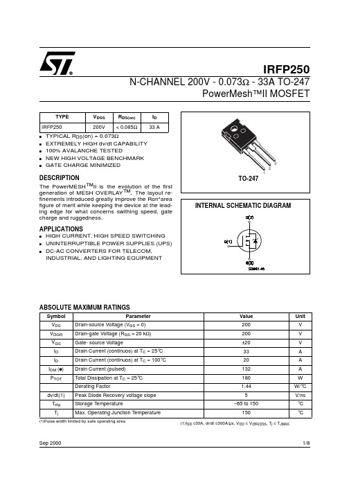
1/8Sep 2000IRFP250N-CHANNEL 200V - 0.073Ω - 33A TO-247PowerMesh™II MOSFETs TYPICAL R DS (on) = 0.073Ωs EXTREMELY HIGH dv/dt CAPABILITY s 100% AVALANCHE TESTEDs NEW HIGH VOLTAGE BENCHMARK sGATE CHARGE MINIMIZEDDESCRIPTIONThe PowerMESH ™II is the evolution of the first generation of MESH OVERLAY ™. The layout re-finements introduced greatly improve the Ron*area figure of merit while keeping the device at the lead-ing edge for what concerns swithing speed, gate charge and ruggedness.APPLICATIONSs HIGH CURRENT, HIGH SPEED SWITCHING s UNINTERRUPTIBLE POWER SUPPLIES (UPS)s DC-AC CONVERTERS FOR TELECOM, INDUSTRIAL, AND LIGHTING EQUIPMENTABSOLUTE MAXIMUM RATINGS(•)Pulse width limited by safe operating areaTYPE V DSS R DS(on)I D IRFP250200V< 0.085Ω33 ASymbol ParameterValue Unit V DS Drain-source Voltage (V GS = 0)200V V DGR Drain-gate Voltage (R GS = 20 k Ω)200V V GS Gate- source Voltage±20V I D Drain Current (continuos) at T C = 25°C 33A I D Drain Current (continuos) at T C = 100°C 20A I DM (q )Drain Current (pulsed)132A P TOT Total Dissipation at T C = 25°C180W Derating Factor1.44W/°C dv/dt(1)Peak Diode Recovery voltage slope 5V/ns T stg Storage Temperature–65 to 150°C T jMax. Operating Junction Temperature150°C(1)I SD ≤33A, di/dt ≤300A/µs, V DD ≤ V (BR)DSS , T j ≤ T JMAX.IRFP2502/8THERMAL DATAAVALANCHE CHARACTERISTICSELECTRICAL CHARACTERISTICS (TCASE = 25 °C UNLESS OTHERWISE SPECIFIED)OFFON (1)DYNAMICRthj-case Thermal Resistance Junction-case Max 0.66°C/W Rthj-amb Thermal Resistance Junction-ambient Max 30°C/W Rthc-sinkThermal Resistance Case-sink Typ0.1°C/W T lMaximum Lead Temperature For Soldering Purpose300°CSymbol ParameterMax ValueUnit I AR Avalanche Current, Repetitive or Not-Repetitive (pulse width limited by T j max)33A E ASSingle Pulse Avalanche Energy(starting T j = 25 °C, I D = I AR , V DD = 50 V)600mJSymbol ParameterTest ConditionsMin.Typ.Max.Unit V (BR)DSS Drain-sourceBreakdown Voltage I D = 250 µA, V GS = 0200V I DSS Zero Gate VoltageDrain Current (V GS = 0)V DS = Max Rating1µA V DS = Max Rating, T C = 125 °C 50µA I GSSGate-body Leakage Current (V DS = 0)V GS = ±30V±100nASymbol ParameterTest ConditionsMin.Typ.Max.Unit V GS(th)Gate Threshold Voltage V DS = V GS , I D = 250 µA 234V R DS(on)Static Drain-source On ResistanceV GS = 10V, I D = 16A 0.0730.085ΩI D(on)On State Drain CurrentV DS > I D(on) x R DS(on)max, V GS =10V33ASymbol ParameterTest ConditionsMin.Typ.Max.Unit g fs Forward Transconductance V DS > I D(on) x R DS(on)max,I D = 16A1025S C iss Input Capacitance V DS = 25V, f = 1 MHz, V GS = 02850pF C oss Output Capacitance 420pF C rssReverse Transfer Capacitance120pF3/8IRFP250ELECTRICAL CHARACTERISTICS (CONTINUED)SWITCHING ONSWITCHING OFFSOURCE DRAIN DIODENote: 1.Pulsed: Pulse duration = 300 µs, duty cycle 1.5 %.2.Pulse width limited by safe operating area.Symbol ParameterTest ConditionsMin.Typ.Max.Unit t d(on)Turn-on Delay Time V DD = 100V, I D =16 A R G =4.7Ω, V GS = 10V (see test circuit, Figure 3)25ns t r Rise Time 50ns Q g Total Gate Charge V DD = 160V, I D = 33 A,V GS = 10V, R G =4.7Ω117158nC Q gs Gate-Source Charge 15nC Q gdGate-Drain Charge50nCSymbol ParameterTest ConditionsMin.Typ.Max.Unit t r(Voff)Off-voltage Rise TimeV DD = 160V, I D = 16 A, R G =4.7Ω, V GS = 10V (see test circuit, Figure 5)60ns t f Fall Time 40ns t cCross-over Time100nsSymbol ParameterTest ConditionsMin.Typ.Max.Unit I SD Source-drain Current 33A I SDM (2)Source-drain Current (pulsed)132A V SD (1)Forward On Voltage I SD = 33 A, V GS = 0 1.6V t rr Reverse Recovery Time I SD = 33 A, di/dt = 100A/µs, V DD = 100V, T j = 150°C (see test circuit, Figure 5)370ns Q rr Reverse Recovery Charge 5.4µC I RRMReverse Recovery Current29AIRFP2504/85/8IRFP250Normalized On Resistance vs TemperatureIRFP2506/8Fig. 5: Test Circuit For Inductive Load Switching And Diode Recovery TimesFig. 4: Gate Charge test CircuitFig. 2: Unclamped Inductive WaveformFig. 1:Unclamped Inductive Load Test CircuitFig. 3: Switching Times Test Circuit ForResistive LoadIRFP2507/8IRFP2508/8Information furnished is believed to be accurate and reliable. However, STMicroelectronics assumes no responsibility for the consequences of use of such information nor for any infringement of patents or other rights of third parties which may result from its use. No license is granted by implication or otherwise under any patent or patent rights of STMicroelectronics. Specification mentioned in this publication are subject to change without notice. This publication supersedes and replaces all information previously supplied. STMicroelectronics products are not authorized for use as critical components in life support devices or systems without express written approval of STMicroelectronics.The ST logo is a trademark of STMicroelectronics© 2000 STMicroelectronics – Printed in Italy – All Rights ReservedSTMicroelectronics GROUP OF COMPANIESAustralia - Brazil - China - Finland - France - Germany - Hong Kong - India - Italy - Japan - Malaysia - Malta - Morocco -Singapore - Spain - Sweden - Switzerland - United Kingdom - U.S.A.。
大功率 场效应管 40A 600V的型号有哪些?
TK6A60D TO-220F定型脚 TOSHIBA DIP/MOS N场 600V 6A 1.25Ω
K6A60D TO-220F定型脚 TOSHIBA DIP/MOS N场 600V 6A 1.25Ω
2SK4026 TOSHIBA TO-251
WFW24N60,TO-3P,600V,24A,0.27Ω
WFW20N60,TO-3P,600V,20A,0.32Ω
AP01L60J AP/富鼎 TO-251
FQU2N60 FAIRCHILD TO-251
SPU02N60C3 infineon TO-251
SPP03N60S5 infineon TO-220
SPP04N60C3 infineon TO-220
SPP04N60S5 infineon TO-220
SSP2N60B FAIRCHILD TO-220
SSP6N60B FAIRCHILD TO-220
SSP7N60 FAIRCHILD TO-220
2SK2003-01MR,TO-220F,FUJ,DIP/MOS,N场,600V,4A
2SK2002-01MR,TO-220F,FUJ,DIP/MOS,N场,600V,3A
FMV06N60E,TO-220F,FUJ,DIP/MOS,N场,600V,6A
SPU04N60S5,TO251,Infineon,DIP/MOS,N场,600V,4.5A,0.95Ω
KIA4N60 TO-220F KIA DIP/MOS N场 600V 4A
KIA2N60 TO-220F KIA DIP/MOS N场 600V 2A 4.4Ω
奇石乐发动机燃烧分析仪说明书

压阻式压力传感器
压阻原理以1954年首次发现的半导体 效应为基础,即在机械应力作用下, 半导体的阻值会发生变化。与传统的 应变仪测量相比,这一发现开拓了全 新的应用领域。从那时起,其他相近 的技术开始出现,如金属薄膜技术和 陶瓷厚膜技术。
开始: – 奇石乐 – 传感器型号 – 版本 – 传感器版本号 – 传感器序号
初始校准: – 工作温度范围 – 初始校准日期 – 初始校准值
再校准: – 参考温度 – 再校准日期 – 再校准值
结尾: – 注释
传感器
密封
连接电缆
传感器、连接电缆和 TEDS 元件
PiezoSmart®适配器
压阻式低压
压电式缸压
PiezoStar®-10 多年来奇石乐在厂内培养高灵 敏和高温稳定的晶体。
2
目录
从晶体到传感器需要 200 道工序
4
奇石乐压力传感器 - 设计的多样化和创新
6
PiezoSmart® 意味着传感器的自动识别
8
技术先驱 - 引导发动机测试技术发展
压电式缸压
PiezoSmart® 传感器
优点概述
● 电荷和电压放大器参数的自动设 置
● 精确压力指示数据测量简便 ● 简化设置过程缩短试验台的测量
准备时间 ● 通过分析系统数据自动交换,简
化测量分析和记录 ● 传感器自动识别技术极大地提高
多通道校准系统的自动化程度
更多关于升级的信息, 请参考第 18 页
摩托拉拉两路通信设备产品说明书

CDM 1550•LS CDM 1550•LS+Professional SeriesTwo-Way Radios and AccessoriesVHF UHF 200 MHz 700 MHzkeeping one step ahead of your competition. You also need communication tools that deliver immediate, reliable access to the people and information you need to get the job done. And that’s exactly what two-way radio gives you.At the touch of a button, two-way radio lets you talk with one, ten, or more people instantly – providing the individual and team communication you need to maximize productivity and meet your customers’ demands. And when you choose aMotorola radio, you know you’re getting a product designed to meet your requirements as a professional.The Intelligent Radio – So Advanced, It Practically Thinks for YouHigh-performing features combined with versatile trunking capabilities make the CDM1550•LS and CDM1550•LS +two-way radios the smart choice to keep mobile work teams performing at their best. The CDM1550•LS and CDM1550•LS +radios incorporate LTR ®trunking capabilities – offering you wide calling range, fast channel access, great privacy,and high user and talkgroup capacity. The CDM1550•LS +also offers innovative PassPort ®trunking. Ideal for users with growing communication needs, PassPort includes all the advantages of LTR trunking plus:• Wide Area Coverage, Seamless Roaming – Automatic switching between networked PassPort sites lets you maintain constant communication over long distances without touching a button• Exceptional Audio Quality – Received Signal StrengthIndicator (RSSI) communication technology utilizes one of the strongest signals available, giving you optimal sound quality• Superior System Access – Automatic site registration/deregistration can reduce busy channels and enhance system efficiency• Efficient Channel Expansion – Direct frequency assignment allows you to add channels and sites over the air without taking radios out of service• Electronic Serial Number Protection – Keeps system resources available by helping to prevent unauthorized radio cloning• Increased Flexibility – Access privileges by Mobile Identification Number* (MIN) allows radios to be directed to specific sites or talkgroups.*Optional PassPort featureCDM1550•LS with LTR ®TrunkingCDM1550•LS and CDM1550•LS +Radio Features15 PassPort and/or LTR Zones (16 talkgroups each)* 16 or 160 Conventional Channels*RSSI IndicatorDisplays signal strength levelLarge Control ButtonsEasy management of menu, navigation, and exit functions Conventional TalkaroundUnit-to-unit communications, bypassing the repeaterHome Channel RevertAutomatic, one-button return to a preferred talkgroup or channel User-Defined ListsChange scan, phone, and call lists on the fly Voice StorageRecord important messages or personal memos Telephone InterconnectPlace and receive phone calls with the radioMDC1200 Signaling (Encode/Decode) Features on Conventional and LTR Zones*• Caller ID – Identifies incoming callers• Selective Call – Lets you call a specific group or individual • Call Alert – Notifies individual users that you ’re trying to reach them • Radio Check – Tells you whether another user ’s radio is activated • Message – Allows you to send and receive pre-programmed messages PassPort Selective Call or Call Alert*Lets you initiate or receive a private call or a private page to a specific userQuick Call II TM on Conventional Zones*Send and receive information via tone or digital signals Roam Request*Optional manual initiation of roaming function Roam Lock*Optional manual lock of the radio onto a site Horn and Lights ActivationNotifies you of calls when you ’re away from your vehicle Additional CDM1550•LS and CDM1550•LS Mobile Features• 12.5/25 kHz switchable channel spacing*• Remote mountable control head • Data capable• Operates on conventional, LTR and PassPort systerms**Only available on certain models. Check with your Motorola Authorized Dealer for availability.Motorola – A Name You Know and TrustFor 75 years, Motorola has been a leader in creating state-of-the-art wireless communications for people like you. The CDM1550•LS and the CDM1550•LS +mobiles uphold that superior standard. What ’s more, each radio is backed by a limited two-year* warranty on parts and labor.So when you select the CDM1550•LS or the CDM1550•LS +mobile, you ’ll experience the same exceptional quality you ’ve come to expect from all Motorola products.*Radio accessories are covered by Motorola ’s one-year accessories warranty.CDM1550•LS +Exceptional Functionality and ConvenienceThe CDM1550•LS and the CDM1550•LS +mobiles utilize the latest in two-way technology to deliver extraordinary performance and ease-of-use, including:• Compact, Ergonomic Design to give you optimal mounting flexibility and durability• 14-Character Alphanumeric Display with User-Friendly Icons to help make the radio ’s information easy to understand • Convenient Menu Navigation so you can program scan,phone, and call lists in virtually no timethe transmissions your radio monitors• Motorola ’s Unique X-Pand ™Audio Enhancement combined with a powerful front-projecting speaker can help reducebackground noise and improve sound quality • Compatible with CES data equipment so that you can configure your radio for specific data applications and needsThe CDM1550•LS +mobile can also be programmed with both LTR and PassPort trunking systems – allowing a smooth transition when your business requires a more extensive calling area for maximum communication efficiency. The radiooperates on 16 or 160 channels as well.Motorola Original ™accessories provide an easy way to turn your CDM1550•LS or CDM1550•LS +mobile radio into a custom communication solution to fit your business requirements —maximizing on-the-job productivity and efficiency for mobile work teams and individuals. Listed below is just a portion of the accessory portfolio available for the CDM1550•LS and CDM1550•LS +. Call today for a complete accessory listing.CDM1550•LS CDM1550•LS+Radio AccessoriesTalk However You WantEnhanced Keypad Microphone —AARMN4026You can dial phone numbers on this microphone ’s full keypad, or customize its three programmable buttons with any control head features.Visor Microphone —AARMN4027Attach this microphone to your visor or hat for hands-free operation of your radio (must be used with an external PTT).Push Button Push-to-Talk —RLN4857Simply depress the button to talk with other users.Foot Switch Push-to-Talk —RLN4856A handy foot switch provides hands-free PTT functionality.Gooseneck Mount Push-to-Talk —RLN4858This PTT mounts conveniently on your steering wheel column for control that ’s right at your fingertips.Telephone Style Handset —AAREX4617 Conduct private conversations on your radio quietly and discreetly.Get Your Message Across13-Watt Speaker —RSN4001Powerful sound control allows you to increase your radio ’s volume output when working in noisy environments.Control Station —RLN5403AThe quick convenient way to convert a CDM Series mobile radio into a fully funtional base station.Take It With YouHigh-Profile Mount —GLN7317Offers a space-saving option for vehicles where every inch counts.Key Lock Mount —RLN4779Securely mounts and locks radio in your vehicle to protect against theft.Power It Up1-25 Watt Power Supply —HPN4002For use with low power radios. Provides power for using mobile radio on a desktop.25-60 Watt Power Supply —HPN4001For use with high power radios. Provides power for using mobile radio on a desktop.Enhance Your Calling Range200 MHz Wave Roof Mount Antenna — HKAD4001140-174 MHz VHF 3dB Gain Roof Mount Antenna —HAD4014494-512 MHz UHF 3.5dB Gain Roof Mount Antenna —HAE4013450-470 MHz UHF 5dB Gain Roof Mount Antenna —RAE4004ARB746-794 MHz 3dB Gain Antenna —RAF4221CDM1550•LS and CDM1550•LS +Radio SpecificationsOperating Temperature -30 to +60°C Storage Temperature -55 to +85°C Thermal Shock -40 to +85°C Humidity 95% RH @ 8 Hr.ESDIEC 801-2 KV Water Intrusion IPX4Packing TestImpact TestApplicable MIL-STD 810C810D810EMethods ProceduresMethods ProceduresMethods ProceduresLow Pressure 500.11500.22500.32High Temperature 501.11,2501.21,2501.31,2Low Temperature 502.12502.21,2502.31,2Temperature Shock 503.11503.21503.31Solar Radiation 505.11505.21505.31Rain 506.12506.22506.32Humidity 507.12507.22,3507.33Salt Fog 509.11509.21509.31Dust 510.11510.21510.31Vibration 514.28,10514.31514.41Shock 516.21,5516.31516.41VHF200 MHzUHF700 MHzFrequencies136–174 MHz,217–218 MHz, 403–470 MHz, 746–747 MHz,219–220 MHz,450–512 MHz 762–764 MHz 220–222 MHZ Channel Spacing 12.5/20/25 kHz 12.5 kHz 12.5/20/25 kHz 12.5 kHz Frequency Stability±2.5 ppm±2.5 ppm±2.5 ppm±1.5 ppm(-30°C to +60°C, +25°Ref.)Sensitivity (12 dB SINAD) EIA 0.3 µV 0.23 µV typical 0.30 µV (0.25 µV typical)0.3 µV 0.23 uV typical 0.35 µV (0.3 µV typical)Intermodulation************75dB************75dB78 dB @ 25 kHz 75 dB @ 25 kHz Adjacent Channel Selectivity ************65 dB (TIA 603)************65 dB (TIA 603)80 dB @ 25 kHz 40 dB (TIA 603-A)75 dB @ 25 kHz 40 dB (TIA 603-A)Spurious Rejection************75 dB ************75 dB 80 dB @ 25 kHz 75 dB @ 25 kHz Rated Audio3W Internal 3W Internal 3W Internal 3W Internal (External audio w/4 ohm speaker)13W External 13W External 13W External 13W External Audio Distortion @ Rated Audio 3% typical 3% typical 3% typical 3% typical Hum and Noise -40 dB 12.5 kHz -40 dB -40 dB 12.5 kHz -40 dB -45 dB 25 kHz-45 dB 25 kHzAudio ResponseTIA603 & ETS300 &+1 to -3 dB TIA603 & ETS3000 & +1 to -3 dB CEPT 84 Annex 2CEPT 84 Annex 2Conducted Spurious Emmision -57dBm < 1 GHZ -57dBm < 1 GHz -57dBm < 1 GHZ -57dBm < 1 GHz FCC Part 15-47dBm > 1 GHZ-47 dBm > 1GHz-47dBm > 1 GHZ-47 dBm > 1GHzVHF200 MHzUHF700 MHzFrequencies136–174 MHz217–218 MHz (Talkaround),403–470 MHz 776–777 MHz, 219–220 MHz,450-512 MHz792 –794 MHz,220–221 MHz (Talkaround),746–747 MHz (Talkaround),221–222 MHz 762–764 MHz (Talkaround)Power Output 1–25 W or 25–45 W 1–25 W 1–25 W or 25–40 W 1–15 W Frequency Stability±2.5 ppm ±2.5 ppm ±5 ppm @ 25 kHz ±1.5 ppm (-30°C to +60°C, +25°Ref.)±**************Modulation Limiting±***********±2.5 kHz±***********±2.5 kHz±4.0 @ 20 kHz ±4.0 @ 20 kHz ±5.0 @ 25 kHz ±5.0 @ 25 kHz Conducted and Radiated -36 dBm < 1 GHz -16 dBm -36 dBm < 1 GHz -16 dBm (except – 40 dBm Emissions-30 dBm > 1 GHz -30 dBm > 1 GHz from 1559 to 1610 MHz)Channel Spacing 12.5/20/25 kHz 12.5 kHz12.5/20/25 kHz 12.5 kHzFM Hum & Noise -40 dB 12.5 kHz - 40 dB typical -40 dB typical - 40 dB typical -45 dB 25 kHz Adjacent Channel Power *************-60 dB *************-60 dB -70 dB @ 25 kHz -70 dB @ 25 kHz Audio Response TIA 603 & ETS300 &+1 to -3 dB TIA 603 & ETS300 &+1 to -3 dB CEPT 84 Annex 2CEPT 84 Annex 2Audio Distortion3% typical3% typical 3% typical3% typical FM Modulation Designator 11K0F3E (12.5 kHz)11K0F3E 11K0F3E (12.5 kHz)11K0F3E 16K0F3E (25 kHz)16K0F3E (25 kHz)Adjacent Channel Coupled PowerN/AN/AN/AComplies with 47 CFR 27.53 (d) (1)VHF200 MHzUHF700 MHzChannel Capacity Trunking zone capacity15151515Trunking talkgroup capacity (per zone)16161616Conventional channel capacity 16 or 1601616 or 16016Typical RF Output VHF Low Power 1-25W VHF High Power 25-45W 200 MHz1-25W UHF Low Power 1-25W UHF High Power 25-40W 700 MHZ 1-15WFrequency VHF 136-174 MHz200 MHz 217-218 MHz, 219-222 MHz UHF 403-470 MHz, 450-512 MHz700 MHz746-747 MHz, 762-764 MHz, 776-777 MHz, 792-794 MHz Dimension (H x W x L)VHF/UHF Low Power and 200 MHz 2.34” x 7.05” x 7.32” (60 mm x 179 mm x 186 mm)VHF/UHF High Power and 700 MHz 2.34” x 7.05” x 7.79” (60 mm x 179 mm x 198 mm)WeightVHF/UHF Low Power and 200 MHz 3.15 lbs. (1.43 kg)VHF/UHF High Power and 700 MHz 3.5 lbs. (1.59 kg)Current Drain VHF 200UHF 700Standby.3 A .3 A .3 A .3 A Rx @ rated, external 8 ohm 1.5 A 1.5 A 1.5 A 1.5 A Transmit 7 A @ 25W 7 A @ 25W 8 A @ 25W 7 A @ 15W 13.5 A @ 45W 13.5 A @ 40W FCC DescriptionAZ492FT3796 (25W, 136-174 MHz)AZ492FT3795 (45W, 136-174 MHz)ABZ99FT3081 (25W, 217-218/219-222 MHz)AZ492FT4835 (25W, 403-470 MHz)AZ492FT4830 (40W, 403-470 MHz)AZ492FT4829 (25W, 450-512 MHz)AZ492FT4836 (40W, 450-512 MHz)ABZ99FT5001 (15W, 746-747/762-764/776-777/792-794 MHZ)MOTOROLA and the Stylized M Logo are registered in the US Patent and Trademark Office. All other product or service names are the property of their respective owners.© Motorola, Inc. 2003./cgissMD-CDM1550LS-04。
洛雷技术IP球机说明书
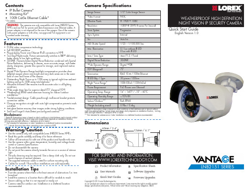
• IP Bullet Camera* • Mounting Kit* • 100ft Cat5e Ethernet Cable*
* Per camera.
WARNING - The cameras are only compatible with Lorex LNR200 Series NVR’s and use PoE for power and data transmission over Ethernet cables. A power adapter is not required for the use of the camera. Use of the camera with power adapters or with other, non-approved PoE equipment is not covered under warranty.
Before installing the camera:
• Decide whether to run the cables through the wall / ceiling (drilling required) or along the wall / ceiling.
recommended
Camera Specifications
Image Sensor
1/3” Color Image Sensor
Video Format
NTSC
Effective Pixels
H: 1920 V: 1080
Resolution
1080P @ 30FPS (Frames Per Second)
Features
• H.264 video compression technology • Full HD1080P resolution • Plug-and-play Power over Ethernet (PoE) connection to NVR • True Day/Night mode: Picture automatically switches to B&W delivering
CP50中文翻译版
CP501、APZ 212 50介绍目标简介APZ 212 50是AXE 10的控制系统,重点关注的是高端容量。
APZ 212 50是为实现更大处理能力的交换节点而提供的。
它利用中央处理器中的高速以太连接来连接I/O和处理器。
这种处理器集成了英特尔的Itanium处理器和HP的运行在Linux上的便携式级别的服务器,再整合爱立信的通信功能从而为未来提供了一个平台。
APZ的演变发展第一代的APZ是APZ 210,从APZ 210 03演变到210 04,最后在1970年代演变为APZ 210 06。
为了提供应用系统的容量例如转接局和国际交换局从而产生了比APZ 210更强的APZ 212处理器。
但是,并不是所有的交换机都需要比APZ 210所可以提供的更多的处理能力。
于是产生了APZ 211。
这种类型的APZ与APZ 210相比没有提供更高处理能力但是生产成本更低。
APZ 212仍在不断发展。
无论处理能力还是存储容量都获得了引人注目的提高,从而产生了今天的超强处理器。
APZ基本概念中央处理器的APZ 212系列一直到APZ 212 33(本章简称传统APZ)都基于专用的平台和操作系统。
APZ 212 40在引入硬件和unix作为操作系统方面等两方面向公开平台迈出了巨大的步伐。
APZ 212 50是继APZ 212 40之后的第二代商用处理器。
虽然APZ的平台有所改变但是一些基本的概念仍保留一样。
APZ 212系列的处理器到APZ 212 33的物理组成都分成独立的两部分单元,分别是指令处理单元(IPU)和信号处理单元(SPU)。
两部分处理单元运行的操作系统主要都由微程序组成,MIP。
SPU根据它们的优先级别分配由应用单元产生的进程,然后由IPU协调执行。
当执行进程的时候IPU会使用存储在程序各自的数据存储中的应用代码和数据内容。
AXE的硬件和软件设备及单元定义在核心软件中。
传统APZ 212系列的核心软件在PLEX中编码然后在转载入APZ前编译成ASA。
(有效参数)IEC60205
13
式中 β = α − arcsin e d2
与 l2 相关的磁心因子:
式中 g = lmin + lmax , D = A7
2lmin
A8
拐角处的平均磁路长度及其相关的平均面积:
14
3.10 EL 型磁心对
注:EL+PLT(平面)磁心对用 EL 型磁心公式计算。
边腿的面积: 边腿的平均磁路长度: 背部面积: 背部平均磁路长度: 中心柱面积: 中心柱的平均磁路长度: 外侧拐角的面积:
l1 = D l3 = D
15
式中 A21 = (B-D)C
外侧拐角的平均磁路长度: 内侧拐角的面积:
式中 A23 = ((F2-F1)+πF1/2)(B-D)
内侧拐角的平均磁路长度:
注:规定这一精度的目的只是为了保证由不同人员所计算的这些参数相同,并不是说这些参数的测
量达到了这样的精确度。
2.2 Amin 是最小横截面的标称值。计算 Amin 所用尺寸均取相应零件图上公差范围的平均值。 2.3 计算只适用于闭合磁路的构件。 2.4 计算时所用尺寸均取相应零件图上公差范围的平均值。 2.5 磁心外形所有不规则部分,如小的倒角,凹槽,缺口等,除另有说明外,可忽略不计。 2.6 当计算零件拐角处时,其平均磁路长度应取两相邻均匀部分截面中心连线的圆弧形路 径。而与其相关的截面积应取两相邻截面积的平均值。
有效参数 le,Ae 和 Ve 的计算。 有效参数可规定为
le
=
C12 C2
Ae
=
C1 C2
式中 le 是磁心的有效磁路长度(mm);
Ae 是有效横截面积(mm2); Ve 是有效体积(mm3); C1 是磁心常数(mm-1); C2 是磁心常数(mm-3)。
IP等级标准(IEC60529)
国际工业标准防水等级IPX的分级标准国际工业防水等级标准IPX和日本工业防水标准的JIS等级是一致的,共分为0-8的9级:0级无保护1级可以消除垂直落下水滴的有害影响2级对与垂直方向在15度以内落下的水滴有防护作用3级可以消除与垂直方向在60度的喷雾状水滴的有害影响4级可以消除从不同方向飞溅水滴的有害影响5级可以消除对各方向喷嘴喷射水流的有害影响6级可以消除对各方向喷嘴强力喷射水流的有害影响7级顶部距离水面0.15—1米,连续30分钟,性能不受影响,不漏水8级顶部距离水面2—30米,连续30分钟,性能不受影响,不漏水IPX防水等级电子测量仪器的防水等级反映了仪器防潮和防尘的能力,特别是对于户外活动中,免不了处于高湿或多尘沙的恶劣环境中,仪器的密封和防水能力对于保证仪器的安全运转和寿命就至关重要。
为此,国际上制订IEC 529标准。
为了与此相适应,日本工业标准中将电子仪器的防水保护分为1 0个等级,分别以IPX1、IPX2……表示。
保护等级种类含义0 无保护1 防滴I型垂直落下的水滴无有害的影响2 防滴II型与垂直方向成15“范围内落下的水滴无有害的影响3 防雨型与垂直方向成60度范围内降雨无有害的影响4 防溅型受任意方向的水飞溅无有害的影响5 防喷射型任意方向直接受到水的喷射无有害的影响6 耐水型任意方向直接受到水的喷射也不会入内部7 防浸型在规定的条件下即使浸在水中也不会进入内部8 水中型长时间浸没在一定压力的水中照样能使用9 防湿型在相对湿度大90%以下的湿气一样能使用IPxx 防水等级国际工业标准防水登记IP和日本工业标准的JIS防水等级是接近的,分0-8的9级,IP等级同样对防尘做了规定。
[编辑本段]IPxx 防尘防水等级防尘等级(第一个X表示)0 :没有保护1 :防止大的固体侵入2 :防止中等大小的固体侵入3 :防止小固体进入侵入4 :防止物体大于1mm 的固体进入5 :防止有害的粉尘堆积6 :完全防止粉尘进入[编辑本段]防水等级(第二个X表示)0 :没有保护1 :水滴滴入到外壳无影响2 :当外壳倾斜到15 度时,水滴滴入到外壳无影响3 :水或雨水从60 度角落到外壳上无影响4 :液体由任何方向泼到外壳没有伤害影响5 :用水冲洗无任何伤害6 :可用于船舱内的环境7 :可于短时间内耐浸水(1m )8 :于一定压力下长时间浸水[编辑本段]测试方法例:有秤或显示仪表标示为IP65,表示产品可以完全防止粉尘进入及可用水冲洗无任何伤害。
- 1、下载文档前请自行甄别文档内容的完整性,平台不提供额外的编辑、内容补充、找答案等附加服务。
- 2、"仅部分预览"的文档,不可在线预览部分如存在完整性等问题,可反馈申请退款(可完整预览的文档不适用该条件!)。
- 3、如文档侵犯您的权益,请联系客服反馈,我们会尽快为您处理(人工客服工作时间:9:00-18:30)。
IPI60R250CPMaximum ratings, at T j =25 °C, unless otherwise specified ParameterSymbol Conditions Unit Continuous diode forward current I S ADiode pulse current2)I S,pulse 40Reverse diode d v /d t 4)d v /d t15V/nsParameter Symbol ConditionsUnitmin.typ.max.Thermal characteristicsThermal resistance, junction - case R thJC -- 1.2K/WR thJA leaded--62Soldering temperature,wavesoldering only allowed at leadsT sold1.6 mm (0.063 in.) from case for 10 s--260°C Electrical characteristics, at T j =25 °C, unless otherwise specified Static characteristicsDrain-source breakdown voltage V (BR)DSS V GS =0 V, I D =250 µA 600--VGate threshold voltageV GS(th)V DS =V GS , I D =0,44 mA 2.533.5Zero gate voltage drain current I DSS V DS =600 V, V GS =0 V, T j =25 °C--1µAV DS =600 V, V GS =0 V, T j =150 °C-10-Gate-source leakage current I GSS V GS =20 V, V DS =0 V --100nA Drain-source on-state resistanceR DS(on)V GS =10 V, I D =7.8 A, T j =25 °C-0.220.25ΩV GS =10 V, I D =7.8 A, T j =150 °C-0.59-Gate resistanceR Gf =1 MHz, open drain-1.3-ΩValue T C =25 °C7.8Values Thermal resistance, junction - ambientIPI60R250CPParameterSymbol ConditionsUnitmin.typ.max.Dynamic characteristics Input capacitance C iss -1200-pFOutput capacitanceC oss-tbd -Effective output capacitance, energyrelated 5)C o(er)-55-Effective output capacitance, time related 6)C o(tr)-150-Turn-on delay time t d(on)-tbd -nsRise timet r -tbd -Turn-off delay time t d(off)-tbd -Fall timet f-tbd-Gate Charge Characteristics Gate to source charge Q gs -6-nCGate to drain charge Q gd -9-Gate charge total Q g -2635Gate plateau voltage V plateau-5.0-VReverse Diode Diode forward voltage V SD V GS =0 V, I F =7.8 A, T j =25 °C-0.9 1.2V Reverse recovery time t rr -tbd -ns Reverse recovery charge Q rr -tbd -µC Peak reverse recovery currentI rrm-tbd-A1)J-STD20 and JESD222)Pulse width t p limited by T j,max4)I SD <=I D , di/dt<=200A/µs, V DClink =400V, V peak <V (BR)DSS , T j <T jmax , identical low side and high side switch.V R =400 V, I F =I S , d i F /d t =100 A/µs5)C o(er) is a fixed capacitance that gives the same stored energy as C oss while V DS is rising from 0 to 80% V DSS.6)C o(tr) is a fixed capacitance that gives the same charging time as C oss while V DS is rising from 0 to 80% V DSS.3)Repetitive avalanche causes additional power losses that can be calculated as P AV =E AR *f.Values V GS =0 V, V DS =100 V, f =1 MHzV DD =400 V,V GS =10 V, I D =x,x A, R G =x,x ΩV DD =400 V, I D =7.8 A, V GS =0 to 10 VV GS =0 V, V DS =0 V to 480 V1 Power dissipation5 Typ. output characteristics9 Typ. gate charge13 Typ. capacitancesIPI60R250CP Definition of diode switching characteristicsIPI60R250CP PG-TO262-3-1: OutlinesDimensions in mm/inchesIPI60R250CPPublished byInfineon Technologies AG81726 München, Germany© Infineon Technologies AG 2006.All Rights Reserved.Attention please!The information given in this data sheet shall in no event be regarded as a guarantee of conditions orcharacteristics (“Beschaffenheitsgarantie”). With respect to any examples or hints given herein, any typicalvalues stated herein and/or any information regarding the application of the device, Infineon Technologieshereby disclaims any and all warranties and liabilities of any kind, including without limitation warranties onon-infringement of intellectual property rights of any third partyInformationFor further information on technology, delivery terms and conditions and prices please contact your nearesInfineon Technologies Office ().WarningsDue to technical requirements components may contain dangerous substances. For information on the typesin question please contact your nearest Infineon Technologies Office.Infineon Technologies Components may only be used in life-support devices or systems with the expresswritten approval of Infineon Technologies, if a failure of such components can reasonably be expected tocause the failure of that life-support device or system, or to affect the safety or effectiveness of that device or system. Life support devices or systems are intended to be implanted in the human body, or to support and/or maintain and sustain and/or protect human life. If they fail, it is reasonable to assume that the health of theuser or other persons may be endangered.。
