1823671中文资料
1-967627-1中文资料
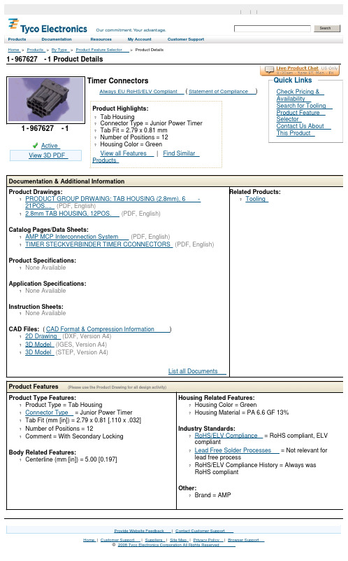
1-967627-1 Product DetailsHome | Customer Support | Suppliers | Site Map | Privacy Policy | Browser Support© 2008 Tyco Electronics Corporation All Rights Reserved SearchProducts Documentation Resources My Account Customer Support Home > Products > By Type > Product Feature Selector > Product Details1-967627-1ActiveView 3D PDF Timer ConnectorsAlways EU RoHS/ELV Compliant (Statement of Compliance)Product Highlights:?Tab Housing?Connector Type = Junior Power Timer?Tab Fit = 2.79 x 0.81 mm?Number of Positions = 12?Housing Color = GreenView all Features | Find SimilarProductsCheck Pricing &AvailabilitySearch for ToolingProduct FeatureSelectorContact Us AboutThis ProductQuick LinksDocumentation & Additional InformationProduct Drawings:?PRODUCT GROUP DRWAING: TAB HOUSING (2.8mm), 6-21POS....(PDF, English)? 2.8mm TAB HOUSING, 12POS.(PDF, English)Catalog Pages/Data Sheets:?AMP MCP Interconnection System(PDF, English)?TIMER STECKVERBINDER TIMER CCONNECTORS(PDF, English) Product Specifications:?None AvailableApplication Specifications:?None AvailableInstruction Sheets:?None AvailableCAD Files: (CAD Format & Compression Information)?2D Drawing (DXF, Version A4)?3D Model (IGES, Version A4)?3D Model (STEP, Version A4)List all Documents Related Products: ?ToolingProduct Features (Please use the Product Drawing for all design activity)Product Type Features:?Product Type = Tab Housing?Connector Type = Junior Power Timer?Tab Fit (mm [in]) = 2.79 x 0.81 [.110 x .032] ?Number of Positions = 12?Comment = With Secondary LockingBody Related Features:?Centerline (mm [in]) = 5.00 [0.197] Housing Related Features:?Housing Color = Green?Housing Material = PA 6.6 GF 13%Industry Standards:?RoHS/ELV Compliance = RoHS compliant, ELVcompliant?Lead Free Solder Processes = Not relevant forlead free process?RoHS/ELV Compliance History = Always wasRoHS compliantOther:?Brand = AMPProvide Website Feedback | Contact Customer Support。
25136中文资料

CHOOSE XTRA•GUARD® 2 FOR:
s s
s s
s
s s
Now Rated To 90°C! Unmatched Resistance to Oils, Fuels, Solvents, and Water Twice the Tensile Strength of PVC Three Times the Tear and Abrasion Resistance of PVC Superior Low-Temperature Flexibility to -20° C Ultraviolet Light Stability (jacket color black) SUPRASHIELD® - Twice as Effective as Foil Shielding
24 AWG (0,23mm2), 7/32 (7x0,20mm), Insulation Thickness: 0.010" (0,25mm) Jacket Thickness Nominal Diameter Part No. No. of Pairs. Inches mm Inches mm
25271 25272 25273 25274 25275 25276 25279 25279/11 25279/15 25279/19 1 2 3 4 5 6 9 11 15 19 0.032 0.032 0.032 0.032 0.032 0.032 0.032 0.032 0.032 0.032 0,81 0,81 0,81 0,81 0,81 0,81 0,81 0,81 0,81 0,81 0.18 0.23 0.25 0.28 0.30 0.31 0.36 0.38 0.43 0.46 4,6 5,8 6,5 7,0 7,5 8,0 9,1 9,7 10,8 11,8
1827347资料
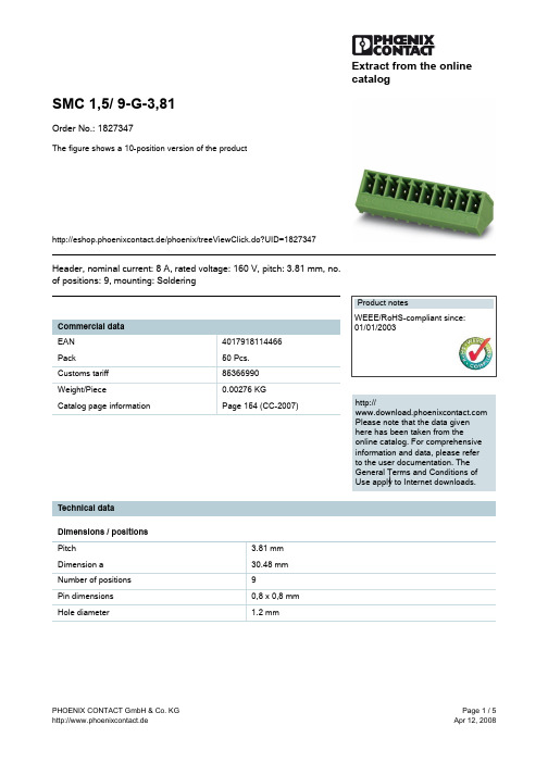
Extract from the onlinecatalogSMC 1,5/ 9-G-3,81Order No.: 1827347The figure shows a 10-position version of the producthttp://eshop.phoenixcontact.de/phoenix/treeViewClick.do?UID=1827347Header, nominal current: 8 A, rated voltage: 160 V, pitch: 3.81 mm, no. of positions: 9, mounting: Solderinghttp://Please note that the data givenhere has been taken from theonline catalog. For comprehensiveinformation and data, please referto the user documentation. TheGeneral Terms and Conditions ofUse apply to Internet downloads. Technical dataDimensions / positionsPitch 3.81 mmDimension a30.48 mmNumber of positions9Pin dimensions0,8 x 0,8 mmHole diameter 1.2 mmTechnical dataInsulating material group IRated surge voltage (III/3) 2.5 kVRated surge voltage (III/2) 2.5 kVRated surge voltage (II/2) 2.5 kVRated voltage (III/2)160 VRated voltage (II/2)320 VConnection in acc. with standard EN-VDENominal current I N8 ANominal voltage U N160 VMaximum load current8 AInsulating material PAInflammability class acc. to UL 94V0Certificates / ApprovalsCSANominal voltage U N300 VNominal current I N8 ACULNominal voltage U N300 VNominal current I N8 AULNominal voltage U N300 VNominal current I N8 ACertification CB, CSA, CUL, GOST, UL, VDE-PZIAccessoriesItem Designation DescriptionMarking0804109SK 3,81/2,8:FORTL.ZAHLEN Marker card, printed horizontally, self-adhesive, 10-section markerstrip, 14 identical decades marked 1-10, 11-20 etc. up to 91-(99)100, sufficient for 140 terminal blocksPlug/Adapter1734634CP-MSTB Coding profile, is inserted into the slot on the plug or invertedheader, red insulating materialAdditional productsItem Designation DescriptionGeneral1851119FK-MCP 1,5/ 9-ST-3,81Plug component, nominal current: 8 A, rated voltage: 160 V, pitch:3.81 mm, no. of positions: 9, type of connection: Spring-cageconnection1850738FRONT-MC 1,5/ 9-ST-3,81Plug component, nominal current: 8 A, rated voltage: 160 V, pitch:3.81 mm, no. of positions: 9, type of connection: Screw connection 1862645IMC 1,5/ 9-G-3,81Header, nominal current: 8 A, rated voltage: 160 V, pitch: 3.81mm, no. of positions: 9, mounting: Soldering1875496IMCV 1,5/ 9-G-3,81Header, nominal current: 8 A, rated voltage: 160 V, pitch: 3.81mm, no. of positions: 9, mounting: Soldering1803646MC 1,5/ 9-ST-3,81Plug component, nominal current: 8 A, rated voltage: 160 V, pitch:3.81 mm, no. of positions: 9, type of connection: Screw connection 1852244MCC 1/ 9-STZ-3,81Plug component, nominal current: 8 A, rated voltage: 160 V, pitch:3.81 mm, no. of positions: 9, type of connection: Crimp connection 1827198MCVR 1,5/ 9-ST-3,81Plug component, nominal current: 8 A, rated voltage: 160 V, pitch:3.81 mm, no. of positions: 9, type of connection: Screw connection 1827046MCVW 1,5/ 9-ST-3,81Plug component, nominal current: 8 A, rated voltage: 160 V, pitch:3.81 mm, no. of positions: 9, type of connection: Screw connection 1897461QC 0,5/ 9-ST-3,81Plug, nominal current: 6 A, rated voltage: 320 V, pitch: 3.81mm, number of positions: 9, connection method: Insulationdisplacement connection QUICKONDrawingsDrilling diagramDimensioned drawingAddressPHOENIX CONTACT GmbH & Co. KGFlachsmarktstr. 832825 Blomberg,GermanyPhone +49 5235 3 00Fax +49 5235 3 41200http://www.phoenixcontact.de© 2008 Phoenix ContactTechnical modifications reserved;。
1850673资料
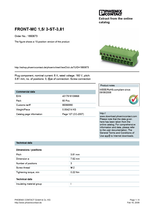
Extract from the onlinecatalogFRONT-MC 1,5/ 3-ST-3,81Order No.: 1850673The figure shows a 10-position version of the producthttp://eshop.phoenixcontact.de/phoenix/treeViewClick.do?UID=1850673Plug component, nominal current: 8 A, rated voltage: 160 V, pitch: 3.81 mm, no. of positions: 3, type of connection: Screw connectionhttp://Please note that the data givenhere has been taken from theonline catalog. For comprehensiveinformation and data, please referto the user documentation. TheGeneral Terms and Conditions ofUse apply to Internet downloads. Technical dataDimensions / positionsPitch 3.81 mmDimension a7.62 mmNumber of positions3Screw thread M 2Tightening torque, min0.22 NmTechnical dataInsulating material group IRated surge voltage (III/3) 2.5 kVRated surge voltage (III/2) 2.5 kVRated surge voltage (II/2) 2.5 kVRated voltage (III/2)160 VRated voltage (II/2)320 VConnection in acc. with standard EN-VDENominal current I N8 ANominal voltage U N160 VNominal cross section 1.5 mm2Maximum load current8 A (with 1.5 mm2 conductor cross section) Insulating material PAInflammability class acc. to UL 94V0Internal cylindrical gage A1Stripping length9 mmConnection dataConductor cross section solid min.0.14 mm2Conductor cross section solid max. 1.5 mm2Conductor cross section stranded min.0.14 mm2Conductor cross section stranded max. 1.5 mm2Conductor cross section stranded, with ferrule0.25 mm2without plastic sleeve min.Conductor cross section stranded, with ferrule1.5 mm2without plastic sleeve max.Conductor cross section stranded, with ferrule0.25 mm2with plastic sleeve min.Conductor cross section stranded, with ferrule0.5 mm2with plastic sleeve max.Conductor cross section AWG/kcmil min.28Conductor cross section AWG/kcmil max162 conductors with same cross section, solid min.0.14 mm22 conductors with same cross section, solid max.0.5 mm22 conductors with same cross section, stranded0.14 mm2min.2 conductors with same cross section, stranded0.75 mm2max.2 conductors with same cross section, stranded,0.25 mm2ferrules without plastic sleeve, min.2 conductors with same cross section, stranded,0.34 mm2ferrules without plastic sleeve, max.2 conductors with same cross section, stranded,0.5 mm2TWIN ferrules with plastic sleeve, min.2 conductors with same cross section, stranded,0.5 mm2TWIN ferrules with plastic sleeve, max.Certificates / ApprovalsApproval logoCSANominal voltage U N300 VNominal current I N8 AAWG/kcmil28-16CULNominal voltage U N300 VNominal current I N8 AAWG/kcmil30-16ULNominal voltage U N300 VNominal current I N8 AAWG/kcmil30-16Certification CB, CSA, CUL, UL, VDE-PZIAccessoriesItem Designation DescriptionMarking1051993B-STIFT Marker pen, for manual labeling of unprinted Zack strips,smear-proof and waterproof, line thickness 0.5 mm0804109SK 3,81/2,8:FORTL.ZAHLEN Marker card, printed horizontally, self-adhesive, 10-sectionmarker strip, 14 identical decades marked 1-10, 11-20 etc. up to91-(99)100, sufficient for 140 terminal blocks0805056SK 3,81/2,8:SO Marker card, special printing, self-adhesive, labeled acc. tocustomer requirements, 14 identical marker strips per card, max.25-position labeling per strip, color: White0803883SK U/2,8 WH:UNBEDRUCKT Unprinted marker cards, DIN A4 format, pitch as desired,self-adhesive, with 50 stamped marker strips, 185 mm strip length,can be labeled with the CMS system or manually with the M-PENTools1205037SZS 0,4X2,5Screwdriver, bladed, matches all screw terminal blocks up to 1.5mm² connection cross section, blade: 0.4 x 2.5 mmAdditional productsItem Designation DescriptionGeneral1897814EMC 1,5/ 3-G-3,81Header, nominal current: 8 A, rated voltage: 160 V, pitch: 3.81mm, no. of positions: 3, mounting: Press in1860650EMCV 1,5/ 3-G-3,81Header, nominal current: 8 A, rated voltage: 160 V, pitch: 3.81mm, no. of positions: 3, mounting: Press in1857896IMC 1,5/ 3-ST-3,81Plug component, nominal current: 8 A, rated voltage: 160 V, pitch:3.81 mm, no. of positions: 3, type of connection: Screw connection 1803280MC 1,5/ 3-G-3,81Header, nominal current: 8 A, rated voltage: 160 V, pitch: 3.81mm, no. of positions: 3, mounting: Soldering1908774MC 1,5/ 3-G-3,81 THT Header, nominal current: 8 A, rated voltage: 160 V, pitch: 3.81mm, no. of positions: 3, mounting: SMD/THT1829963MCD 1,5/ 3-G-3,81Header, nominal current: 8 A, rated voltage: 160 V, pitch: 3.81mm, no. of positions: 3, mounting: Soldering1843088MCD 1,5/ 3-G1-3,81Header, nominal current: 8 A, rated voltage: 160 V, pitch: 3.81mm, no. of positions: 3, mounting: Soldering1830415MCDV 1,5/ 3-G-3,81Header, nominal current: 8 A, rated voltage: 160 V, pitch: 3.81mm, no. of positions: 3, mounting: Soldering1847738MCDV 1,5/ 3-G1-3,81Header, nominal current: 8 A, rated voltage: 160 V, pitch: 3.81mm, no. of positions: 3, mounting: Soldering1861730MCO 1,5/ 3-GL-3,81Header, nominal current: 8 A, rated voltage: 125 V, pitch: 3.81mm, no. of positions: 3, mounting: Soldering1861659MCO 1,5/ 3-GR-3,81Header, nominal current: 8 A, rated voltage: 125 V, pitch: 3.81mm, no. of positions: 3, mounting: Soldering1803439MCV 1,5/ 3-G-3,81Header, nominal current: 8 A, rated voltage: 160 V, pitch: 3.81mm, no. of positions: 3, mounting: Soldering1832701MCVDU 1,5/ 3-G-3,81Header, nominal current: 8 A, rated voltage: 160 V, pitch: 3.81mm, no. of positions: 3, mounting: Soldering1832743MCVK 1,5/ 3-G-3,81Header, nominal current: 8 A, rated voltage: 160 V, pitch: 3.81mm, no. of positions: 3, mounting: Mounting rail1827282SMC 1,5/ 3-G-3,81Header, nominal current: 8 A, rated voltage: 160 V, pitch: 3.81mm, no. of positions: 3, mounting: SolderingDrawingsDimensioned drawingAddressPHOENIX CONTACT GmbH & Co. KGFlachsmarktstr. 832825 Blomberg,GermanyPhone +49 5235 3 00Fax +49 5235 3 41200http://www.phoenixcontact.de© 2008 Phoenix ContactTechnical modifications reserved;。
1873265中文资料
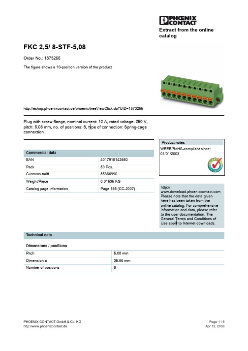
Extract from the onlinecatalogFKC 2,5/ 8-STF-5,08Order No.: 1873265The figure shows a 10-position version of the producthttp://eshop.phoenixcontact.de/phoenix/treeViewClick.do?UID=1873265Plug with screw flange, nominal current: 12 A, rated voltage: 250 V, pitch: 5.08 mm, no. of positions: 8, type of connection: Spring-cage connectionhttp://Please note that the data givenhere has been taken from theonline catalog. For comprehensiveinformation and data, please referto the user documentation. TheGeneral Terms and Conditions ofUse apply to Internet downloads. Technical dataDimensions / positionsPitch 5.08 mmDimension a35.56 mmNumber of positions8Technical dataInsulating material group IRated surge voltage (III/3) 4 kV Rated surge voltage (III/2) 4 kV Rated surge voltage (II/2) 4 kV Rated voltage (III/2)320 V Rated voltage (II/2)630 V Connection in acc. with standard EN-VDE Nominal current I N12 A Nominal voltage U N250 V Nominal cross section 2.5 mm2 Maximum load current12 A Insulating material PA Inflammability class acc. to UL 94V0 Internal cylindrical gage A2 Stripping length10 mmConnection dataConductor cross section solid min.0.2 mm2 Conductor cross section solid max. 2.5 mm2 Conductor cross section stranded min.0.2 mm2 Conductor cross section stranded max. 2.5 mm2 Conductor cross section stranded, with ferrule0.25 mm2 without plastic sleeve min.Conductor cross section stranded, with ferrule2.5 mm2 without plastic sleeve max.Conductor cross section stranded, with ferrule0.25 mm2 with plastic sleeve min.Conductor cross section stranded, with ferrule2.5 mm2 with plastic sleeve max.Conductor cross section AWG/kcmil min.24 Conductor cross section AWG/kcmil max122 conductors with same cross section, stranded,0.5 mm2 TWIN ferrules with plastic sleeve, min.2 conductors with same cross section, stranded,1.5 mm2 TWIN ferrules with plastic sleeve, max.Certificates / ApprovalsCULNominal voltage U N300 VNominal current I N10 AAWG/kcmil26-12ULNominal voltage U N300 VNominal current I N10 AAWG/kcmil26-12Certification CB, CUL, GOST, UL, VDE-PZIAccessoriesItem Designation DescriptionAssembly1876880STZ 8-FKC-5,08Strain relief for snapping into the latching chambers of the plugcomponents, 8-pos.1876877STZ 4-FKC-5,08Strain relief for snapping into the latching chambers of the plugs,4-pos.Marking0804293SK 5,08/3,8:FORTL.ZAHLEN Marker card, printed horizontally, self-adhesive, 12 identicaldecades marked 1-10, 11-20 etc. up to 91-(99)100, sufficient for120 terminal blocksPlug/Adapter1734634CP-MSTB Coding profile, is inserted into the slot on the plug or invertedheader, red insulating material0201744MPS-MT Test plug, consisting of: Metal part for 2.3 mm diameter sockethole0201647RPS Reducing plug, for transition from 4 mm diameter test plug socket,insulation: grayTools1205053SZS 0,6X3,5Screwdriver, bladed, matches all screw terminal blocks up to 4.0mm² connection cross section, blade: 0.6 x 3.5 mm, without VDEapprovalAdditional productsItem Designation DescriptionGeneral1803015MSTBVK 2,5/ 8-GF-5,08Header, nominal current: 12 A, rated voltage: 320 V, pitch: 5.08mm, no. of positions: 8, mounting: Mounting rail1788402MVSTBU 2,5/ 8-GFB-5,08Header, nominal current: 12 A, rated voltage: 320 V, pitch: 5.08mm, no. of positions: 8, mounting: Direct mounting3002034UK 3-MSTB-5,08Modular terminal blocks with plug entry, cross section: 0.2 - 2.5mm², AWG: 30 - 12, width: 5.1 mm, color: gray3002076UK 3-MVSTB-5,08Modular terminal blocks with plug entry, cross section: 0.2 - 2.5mm², AWG: 26 - 12, width: 5.1 mm, color: gray3002102UK 3-MVSTB-5,08-LA 24RD Modular terminal block with plug entry, nominal current: 12 A,rated voltage: 320 V, pitch: 5.08 mm, no. of positions: 1, mounting:mounting rail, with red light indicator, voltage light indicator: 24 VAC/DC, current light indicator: 3.3 mA3002063UK 3-MVSTB-5,08/EK Modular terminal blocks with plug entry, cross section: 0.2-2.5mm², AWG: 26-12, width: 5.1 mm, color: blue3002131UK 3D-MSTBV-5,08Modular terminal blocks with vertical plug entry, cross section: 0.2- 2.5 mm, AWG: 30 - 12, width: 5.1 mm, color: gray3002144UK 3D-MSTBV-5,08-LA 24RD Modular terminal block with vertical plug entry, color: Gray, withred light indicator, voltage light indicator: 24 V AC/DC, current lightindicator: 3.3 mA3002173UK 3D-MSTBV-5,08/EK Modular terminal blocks with plug entry, cross section: 0.2 - 2.5mm², AWG: 30 - 12, width: 5.1 mm, color: blue2770888UKK 3-MSTB-5,08Modular terminal blocks with 2 horizontal plug entries, crosssection: 0.2 - 2.5 mm, AWG: 30 - 12, width: 5.1 mm, color: gray 1876615UKK 3-MSTB-5,08-PE Ground terminal block, with 2 horizontal plug entries, nominalcurrent: 12 A, rated voltage: 320 V, pitch: 5.08 mm, no. ofpositions: 1, mounting: mounting rail.1787982UMSTBVK 2,5/ 8-GF-5,08Header, nominal current: 12 A, rated voltage: 320 V, pitch: 5.08mm, no. of positions: 8, mounting: Mounting rail1873016ZFKK 1,5-MSTBV-5,08Modular terminal blocks with plug entry, cross section: 0.2 - 1.5mm², width: 5.1 mm, color: grayDrawings Dimensioned drawingAddressPHOENIX CONTACT GmbH & Co. KGFlachsmarktstr. 832825 Blomberg,GermanyPhone +49 5235 3 00Fax +49 5235 3 41200http://www.phoenixcontact.de© 2008 Phoenix ContactTechnical modifications reserved;。
LB1836M中文资料
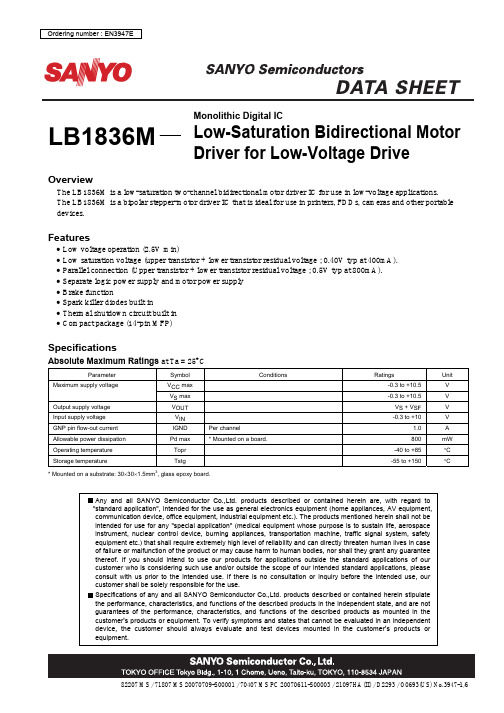
LB1836MOverviewThe LB1836M is a low-saturation two-channel bidirectional motor driver IC for use in low-voltage applications. The LB1836M is a bipolar stepper-motor driver IC that is ideal for use in printers, FDDs, cameras and other portable devices.Features• Low voltage operation (2.5V min)• Low saturation voltage (upper transistor + lower transistor residual voltage ; 0.40V typ at 400mA). • Parallel connection (Upper transistor + lower transistor residual voltage ; 0.5V typ at 800mA). • Separate logic power supply and motor power supply • Brake function• Spark killer diodes built in• Thermal shutdown circuit built in • Compact package (14-pin MFP)SpecificationsAbsolute Maximum Ratings at Ta = 25°CParameter SymbolConditionsRatingsUnitV CC max -0.3 to +10.5V Maximum supply voltageV S max-0.3 to +10.5V Output supply voltage V OUT V S + V SF V Input supply voltage V IN-0.3 to +10V GNP pin flow-out current IGND Per channel1.0 A Allowable power dissipation Pd max * Mounted on a board. 800mW Operating temperature Topr -40 to +85°C Storage temperatureTstg-55 to +150°C* Mounted on a substrate: 30×30×1.5mm 3, glass epoxy board.Monolithic Digital ICLow-Saturation Bidirectional Motor Driver for Low-Voltage DriveAllowable Operating Ranges at Ta = 25°CParameter SymbolConditionsRatingsUnit V CC 2.5 to 9.0V Supply voltageV S1.8 to 9.0V Input “H”-level voltage V IH 1.8 to 9.0V Input “L”-level voltageV IL-0.3 to +0.7VElectrical Characteristics at Ta = 25°C, V CC = VS = 3VRatingsParameter SymbolConditionsmin typ maxUnitI CC 0 V IN 1, 2, 3, 4 = 0V, I CC + I S 0.1 10µAI CC 1 V IN 1 = 3V, V IN 2, 3, 4 = 0V, I CC + I S 14 20mASupply currentI CC 2 V IN 1, 2 = 3V, V IN 3, 4 = 0V, I CC + I S 22 35mAV OUT 1 I OUT= 200mA 0.20 0.28V V OUT 2 I OUT = 400mA0.40 0.60V V OUT 3 I OUT = 400mA, Parallel connection 0.25 0.35V Output saturation voltage (upper + lower)V OUT 4 I OUT = 800mA, Parallel connection0.500.70V Output sustain voltage V O (SUS)I OUT = 400mA 9V Input current I INV IN = 2V, V CC = 6V80µASpark killer diode Reverse current I S (leak) V CC 1, 2 = 9V 30µA Forward voltageV SFI OUT = 400mA1.7VPackage Dimensionsunit : mm (typ) 3111APin AssignmentNote) Ground both GND pins.Ambient temperature, Ta -- °CA l l o w a b l e p o w e r d i s s i p a t i o n , P d m a x -- m W14GND 1V CC 13IN32IN112OUT33OUT111VS24VS110OUT45OUT29IN46IN28Vcont 7GNDLB1836MTop viewBlock DiagramIN1IN2IN3IN4Truth TableOUT2/4 Mode IN1/3 IN2/4 OUT1/3ForwardH L H LReverse L H L HH H L L BrakeStandby L L OFFOFFDesign NotesIf large current flows on the power supply (V S) line and the GND line, then in some applications and layouts, misoperation due to line oscillation may result.The modes during which large current flows are as follows :• Motor surge current when the DC motor starts up or when it shifts rotation directions (forward ↔ reverse).• Passthrough current generated within the IC when shifting rotation directions (forward ↔ reverse) or when shifting from forward/reverse rotation to braking, or vice versa.The following points should be kept in mind regarding the pattern layout :• Keep the wiring lines thick and short in order to reduce wiring inductance between the power supply (V S) and GND. • Insert a passthrough capacitor near the IC. (Maximum effect is obtained by inserting the passthrough capacitor between VS and the pin 7 GND at the closest distance possible.• If the CPU and the LB1836M are mounted on separate boards and the difference between the ground potential of each board is large, install resistors of about 10kΩ in series between the CPU and the LB1836M inputs.Vcont pinAs shown in the above diagram, the Vcont pin outputs the voltage of the band gap Zener V Z + V F (=1.93V).In normal use, this pin is left open.The drive current ID is varied by the Vcont voltage. However, because the band gap Zener is shared, it functions as a bridge.0.20.40.60.81.00200100300400500600Output current, I O –mAO u t p u t s a t u r a t i o n v o l t a g e , V O (s a t )–VAmbient temperature, Ta –°CO u t p u t s a t u r a t i o n v o l t a g e , V O (s a t )–VAmbient temperature, Ta –°CC u r r e n t d r a i n , I S –m AAmbient temperature, Ta –°CC u r r e n t d r a i n , I C C –m ASupply voltage, V CC –VC u r r e n t d r a i n , I C C –m AOutput current, I O –mAO u t p u t s a t u r a t i o n v o l t a g e , V O (s a t )–VAmbient temperature, Ta –°CI n p u t c u r r e n t , I I N –µAV O (sat) – I OInput voltage, V IN –V I n p u t c u r r e n t , I I N –µAThis catalog provides information as of January, 2007. Specifications and information herein are subject This catalog provides information as of August, 2007. Specifications and information herein are subject to change without notice.Supply voltage, V S –VC u r r e n t d r a i n , I S –m A。
1523中文资料

2.5 (.098) x 0.5 (.020) 52.0 (2.047)
SPECIFICATION
CONTACT FORM CONTACT MATERIAL SWITCHING CAPACITY SWITCHING VOLTAGE SWITCHING CURRENT CARRYING CURRENT DIELECTRIC STRENGTH CONTACT RESISTANCE INSULATION RESISTANCE PULL-IN SENSITIVITY DROP-OUT SENSITIVITY SWITCHING TIME WITHOUT BOUNCE BOUNCE TIME RELEASE TIME RESONANT FREQUENCY OPERATING FREQUENCY VIBRATION SHOCK CAPACITANCE OPERATING TEMP. RANGE TEST COIL Typ. Deg. Type Min. Max. Max. Max. Typ. Max. 10-1000 Max. Max. Max. Max. Min. Max. Min. W/VA Vac/dc A A Vdc mΩ Ω AT AT ms ms ms Hz Hz Hz G pF ˚C A Rhodium 120 250 3.0 5.0 800 80 1011 75 - 95 30 3.5 0.5 0.2 900 100 35 50 0.8 -40 +125 1500
Ordering Information PART NUMBER 1523 75 95
We can supply custom cut and formed switches
NOTE: When cutting or bending switch leads it is important that the glass seal is not damaged. The cutting or bending point should be no closer than 3mm (.118) to the glass to metal seal and the lead should be supported between the cutting or bending point and the glass to metal seal.
1824382资料
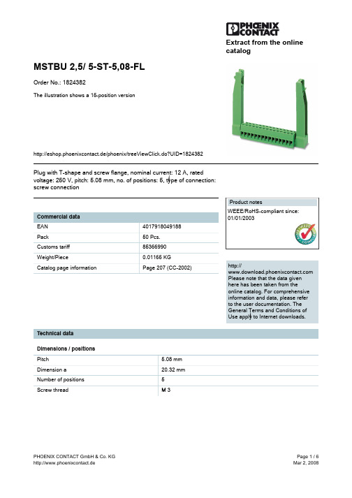
Extract from the onlinecatalogMSTBU 2,5/ 5-ST-5,08-FLOrder No.: 1824382The illustration shows a 15-position versionhttp://eshop.phoenixcontact.de/phoenix/treeViewClick.do?UID=1824382Plug with T-shape and screw flange, nominal current: 12 A, rated voltage: 250 V, pitch: 5.08 mm, no. of positions: 5, type of connection: screw connectionhttp://Please note that the data givenhere has been taken from theonline catalog. For comprehensiveinformation and data, please referto the user documentation. TheGeneral Terms and Conditions ofUse apply to Internet downloads. Technical dataDimensions / positionsPitch 5.08 mmDimension a20.32 mmNumber of positions5Screw thread M 3Tightening torque, min0.5 NmTechnical dataInsulating material group IRated surge voltage (III/3) 4 kV Rated surge voltage (III/2) 4 kV Rated surge voltage (II/2) 4 kV Rated voltage (III/2)320 V Rated voltage (II/2)630 V Connection in acc. with standard EN-VDE Nominal current I N12 A Nominal voltage U N250 V Nominal cross section 2.5 mm2 Insulating material PA Inflammability class acc. to UL 94V0 Internal cylindrical gage A3 Stripping length7 mmConnection dataConductor cross section solid min.0.2 mm2 Conductor cross section solid max. 2.5 mm2 Conductor cross section stranded min.0.2 mm2 Conductor cross section stranded max. 2.5 mm2 Conductor cross section stranded, with ferrule0.25 mm2 without plastic sleeve min.Conductor cross section stranded, with ferrule2.5 mm2 without plastic sleeve max.Conductor cross section stranded, with ferrule0.25 mm2 with plastic sleeve min.Conductor cross section stranded, with ferrule2.5 mm2 with plastic sleeve max.2 conductors with same cross section, solid min.0.2 mm2 2 conductors with same cross section, solid max. 1 mm22 conductors with same cross section, stranded0.2 mm2 min.2 conductors with same cross section, stranded1.5 mm2 max.2 conductors with same cross section, stranded,ferrules without plastic sleeve, min.0.25 mm 22 conductors with same cross section, stranded,ferrules without plastic sleeve, max.1 mm22 conductors with same cross section, stranded,TWIN ferrules with plastic sleeve, min.0.5 mm 22 conductors with same cross section, stranded,TWIN ferrules with plastic sleeve, max. 1 mm 2Conductor cross section AWG/kcmil min.24Conductor cross section AWG/kcmil max 12Certificates / ApprovalsApproval logoCSANominal voltage U N 300 V Nominal current I N 10 A AWG/kcmil 28-12CULNominal voltage U N 300 V Nominal current I N 10 A AWG/kcmil 30-12ULNominal voltage U N 300 V Nominal current I N 10 A AWG/kcmil 30-12Certification CB, CSA, CUL, GOST, UL, VDE-PZIAccessories Item Designation DescriptionAssembly 1808353FLRP/ICV 80Pair of guide rails, is inserted into the groove ICV/...G, height: 86mm, hole diameter: 3.4 mmGeneral1733169EBP 2- 5Insertion bridge, fully insulated, for plug connectors with 5.0 or5.08 mm pitch, no. of positions: 2Marking0804293SK 5,08/3,8:FORTL.ZAHLEN Marker card, printed horizontally, self-adhesive, 12 identicaldecades marked 1-10, 11-20 etc. up to 91-(99)100, sufficient for120 terminal blocksPlug/Adapter1734634CP-MSTB Coding profile, is inserted into the slot on the plug or invertedheader, red insulating materialTools1205053SZS 0,6X3,5Screwdriver, bladed, matches all screw terminal blocks up to 4.0mm² connection cross section, blade: 0.6 x 3.5 mm, without VDEapprovalAdditional productsItem Designation DescriptionGeneral1759046MSTB 2,5/ 5-G-5,08Header, nominal current: 12 A, rated voltage: 250 V, pitch: 5.08mm, no. of positions: 5, mounting: Soldering1757271MSTBA 2,5/ 5-G-5,08Header, nominal current: 12 A, rated voltage: 250 V, pitch: 5.08mm, no. of positions: 5, mounting: SolderingDrawingsDrilling diagramDimensioned drawingAddressPHOENIX CONTACT GmbH & Co. KGFlachsmarktstr. 832825 Blomberg,GermanyPhone +49 5235 3 00Fax +49 5235 3 41200http://www.phoenixcontact.de© 2008 Phoenix ContactTechnical modifications reserved;。
6277中文资料

Data Sheet26185.2028-BIT SERIAL-INPUT, CONSTANT-CURRENT LATCHED LED DRIVERAlways order by complete part number, e.g., A6277EA .The A6277x is specifically designed for LED-display applications.Each BiCMOS device includes an 8-bit CMOS shift register, accompa-nying data latches, and eight npn constant-current sink drivers. Two package styles and two operating temperature ranges are available.The CMOS shift register and latches allow direct interfacing with microprocessor-based systems. With a 5 V logic supply, typical serial data-input rates are up to 20 MHz. The LED drive current is deter-mined by the user’s selection of a single resistor. A CMOS serial data output permits cascade connections in applications requiring additional drive lines. For inter-digit blanking, all output drivers can be disabled with an ENABLE input high. In addition, a HIGH/LOW functionenables full selected current with the application of a logic low, or 50%selected current with the application of a logic high.The first character of the part number suffix determines the device operating temperature range. Suffix ‘E–’ is for -40°C to +85°C, and suffix ‘S–’ is -20°C to +85°C. Two package styles are provided for through-hole DIP (suffix ‘–A’) or surface-mount SOIC (suffix ‘–LW’)applications. The copper lead frame and low logic-power dissipation allow the dual in-line package to sink 122 mA through all outputs continuously over the operating temperature range (1.0 V drop,+85°C).6277PRELIMINARY INFORMATION(Subject to change without notice)July 20, 2000FEATURESI To 150 mA Constant-Current Outputs I 24 V OutputsI Under-Voltage LockoutI Low-Power CMOS Logic and Latches I High Data Input RateI Similar to Toshiba TD62715FN I High/Low Output Current Function115 Northeast Cutoff, Box 15036Worcester, Massachusetts 01615-0036 (508) 853-********8-BIT SERIAL-INPUT,CONSTANT-CURRENT LATCHED LED DRIVER2Copyright © 2000, Allegro MicroSystems, Inc.50751001251502.50.5A L L O W AB L E P AC K A G E P O W E RD I S S I P A T I O N I N W A T T SAMBIENT TEMPERATURE IN °C2.01.51.025SUFFIX 'A', R = 55°C/W θJADwg. GP-018-1SUFFIX 'LW', R = 70°C/W θJAFUNCTIONAL BLOCK DIAGRAMLOGIC GROUNDLATCH ENABLE CLOCK SERIAL DATA IN POWER GROUND POWER GROUND62778-BIT SERIAL-INPUT,CONSTANT-CURRENT LATCHED LED DRIVER3TRUTH TABLEL = Low Logic (Voltage) Level H = High Logic (Voltage) Level X = Irrelevant P = Present State R = Previous StateCLOCK and SERIAL DATA INSERIAL DATA OUTLATCH ENABLE and HIGH/LOWOUTPUT ENABLE (active low)Dwg. EP-010-6IN Dwg. EP-010-7INDwg. EP-010-5IN115 Northeast Cutoff, Box 15036Worcester, Massachusetts 01615-0036 (508) 853-500062778-BIT SERIAL-INPUT,CONSTANT-CURRENT LATCHED LED DRIVER4ELECTRICAL CHARACTERISTICS at T A = +25°C, V H/L = V DD = 5 V (unless otherwise noted).LimitsCharacteristic Symbol Test Conditions Min.Typ.Max.Unit Supply Voltage Range V DD Operating 4.5 5.0 5.5V Under-Voltage Lockout V DD(UV)V DD = 0 to 5 V3.4–4.0V Output Current I OV CE = 1.0 V, R EXT = 160 Ω100120140mA (any single output)V CE = 0.4 V, R EXT = 470 Ω344248mAOutput Current Matching ∆I O0.4 V ≤ V CE(A) = V CE(B) ≤ 1.0 V:(difference between any R EXT = 160 Ω–±1.5±6.0%two outputs at same V CE )R EXT = 470 Ω–±1.5±6.0%Output Leakage Current I CEX V OH = 20 V– 1.0 5.0µA Logic Input VoltageV IH 0.7V DD––V V IL––0.3V DD V SERIAL DATA OUT Voltage V OL I OL = 1.0 mA ––0.4V (SDO 1 & SDO 2)V OH I OH = -1.0 mA 4.6––V Input ResistanceR IENABLE input, pull up150300600k ΩLATCH & HIGH/LOW inputs, pull down100270400k ΩSupply CurrentI DD(OFF)R EXT = open, V OE = 5 V –0.8 1.6mA R EXT = 470 Ω, V OE = 5 V 3.5 6.59.5mA R EXT = 160 Ω, V OE = 5 V141722mA I DD(ON)R EXT = 470 Ω, V OE = 0 V 5.01015mA R EXT = 160 Ω, V OE = 0 V202740mATypical Data is at V DD = 5 V and is for design information only.62778-BIT SERIAL-INPUT,CONSTANT-CURRENT LATCHED LED DRIVER5RECOMMENDED OPERATING CONDITIONSCharacteristic Symbol ConditionsMin.Typ.Max.Unit Supply Voltage V DD 4.5 5.0 5.5V Output Voltage V O – 1.0 4.0V Output CurrentI O Continuous, any one output ––150mA I OH SERIAL DATA OUT ––-1.0mA I OLSERIAL DATA OUT –– 1.0mA Logic Input VoltageV IH 0.7V DD––V V IL––0.3V DD V Clock Frequencyf CKCascade operation ––10MHzSWITCHING CHARACTERISTICS at T A = 25°C, V DD = V IH = 5 V, V CE = 0.4 V, V IL = 0 V,R EXT = 470 Ω, I O = 40 mA, V L = 3 V, R L = 65 Ω, C L = 10.5 pF.LimitsCharacteristicSymbol Test Conditions Min.Typ.Max.Unit Propagation Delay Timet pHLCLOCK-OUT n –3501000ns LATCH-OUT n –3501000ns ENABLE-OUT n–3501000ns CLOCK-SERIAL DATA OUT 1–80110ns Propagation Delay Timet pLHCLOCK-OUT n –3001000ns LATCH-OUT n –4001000ns ENABLE-OUT n–3801000ns CLOCK-SERIAL DATA OUT 2–80110ns Output Fall Time t f 90% to 10% voltage 1502501000ns Output Rise Timet r10% to 90% voltage150250600ns115 Northeast Cutoff, Box 15036Worcester, Massachusetts 01615-0036 (508) 853-500062778-BIT SERIAL-INPUT,CONSTANT-CURRENT LATCHED LED DRIVER6TIMING REQUIREMENTS and SPECIFICATIONS(Logic Levels are V DD and Ground)A.Data Active Time Before Clock Pulse(Data Set-Up Time), t su(D).......................................... 60 ns B.Data Active Time After Clock Pulse(Data Hold Time), t h(D).............................................. 20 ns C.Clock Pulse Width, t w(CK)............................................... 50 ns D.Time Between Clock Activationand Latch Enable, t su(L)............................................ 100 ns tch Enable Pulse Width, t w(L)................................... 100 ns F.Output Enable Pulse Width, t w(OE)................................ 4.5 µs NOTE – Timing is representative of a 10 MHz clock.Significantly higher speeds are attainable.—Max. Clock Transition Time, t r or t f .............................. 10 µsInformation present at any register is transferred to the respective latch when the LATCH ENABLE is high (serial-to-parallel conversion). The latches will continue to accept new data as long as the LATCH ENABLE is held high. Applica-tions where the latches are bypassed (LATCH ENABLE tied high) will require that the OUTPUT ENABLE input be high during serial data entry.When the OUTPUT ENABLE input is high, the output source drivers are disabled (OFF). The information stored in the latches is not affected by the OUTPUT ENABLE input. With the OUTPUT ENABLE input low, the outputs are controlled by the state of their respective latches.OUT Dwg. WP-030-1OUT Dwg. WP-029-362778-BIT SERIAL-INPUT,CONSTANT-CURRENT LATCHED LED DRIVER7ALLOWABLE OUTPUT CURRENT AS A FUNCTION OF DUTY CYCLEA6277xA A6277xLW20DUTY CYCLE IN PER CENT 1000 Dwg. GP-062-17A L L O W AB L E O U T P U TC U R R E N T I N m A /B I T6040204060100808012014020DUTY CYCLE IN PER CENT 1000 Dwg. GP-062-15A L L O W AB L E O U T P U TC U R R E N T I N m A /B I T6040204060100808012014020DUTY CYCLE IN PER CENT1000 Dwg. GP-062-14A L L O W AB L E O U T P U TC U R R E N T I N m A /B I T6040204060100808012014020DUTY CYCLE IN PER CENT1000 Dwg. GP-062-16A L L O W AB L E O U T P U TC U R R E N T I N m A /B I T60402040601008080120140115 Northeast Cutoff, Box 15036Worcester, Massachusetts 01615-0036 (508) 853-500062778-BIT SERIAL-INPUT,CONSTANT-CURRENT LATCHED LED DRIVER820DUTY CYCLE IN PER CENT 1000 Dwg. GP-062-13A L L O W AB L E O U T P U TC U R R E N T I N m A /B I T6040204060100808012014020DUTY CYCLE IN PER CENT1000 Dwg. GP-062-12A L L O W AB L E O U T P U TC U R R E N T I N m A /B I T60402040601008080120140ALLOWABLE OUTPUT CURRENT AS A FUNCTION OF DUTY CYCLE (cont.)A6277xA A6277xLWTYPICAL CHARACTERISTICS0.5Dwg. GP-063-11.02.01.5V CE IN VOLTS06040O U T P U T C U R R E N T I N m A /B I T2062778-BIT SERIAL-INPUT,CONSTANT-CURRENT LATCHED LED DRIVER9TERMINAL DESCRIPTIONTerminal No.Terminal Name Function1LOGIC GROUND Reference terminal for control logic.2SERIAL DATA INSerial-data input to the shift-register.3CLOCK Clock input terminal for data shift on rising edge.4LATCH ENABLE Data strobe input terminal; serial data is latched with high-level input.5HIGH/LOW Logic low for 100% of programmed current level;(CURRENT)logic high for 50% of programmed current level.6POWER GROUNDGround.7-14OUT 0-7The eight current-sinking output terminals.15POWER GROUND Ground.16 OUTPUT ENABLE When (active) low, the output drivers are enabled; when high, all output drivers are turned OFF (blanked).17SERIAL OUT 2CMOS serial-data output (on clock falling edge).18SERIAL OUT 1CMOS serial-data output (on clock rising edge)to the following shift-registers.19R EXTAn external resistor at this terminal establishes the output current for all sink drivers.20LOGIC SUPPLY(V DD ) The logic supply voltage. Typically 5 V.The products described here are manufactured under one or more U.S. patents or U.S. patents pending.Allegro MicroSystems, Inc. reserves the right to make, from time to time, such departures from the detail specifications as may berequired to permit improvements in the performance, reliability, or manufacturability of its products. Before placing an order, the user is cautioned to verify that the information being relied upon is current.Allegro products are not authorized for use as critical components in life-support devices or systems without express written approval.The information included herein is believed to be accurate and reliable. However, Allegro MicroSystems, Inc. assumes no responsi-bility for its use; nor for any infringement of patents or other rights of third parties which may result from its use.115 Northeast Cutoff, Box 15036Worcester, Massachusetts 01615-0036 (508) 853-500062778-BIT SERIAL-INPUT,CONSTANT-CURRENT LATCHED LED DRIVER10The load current per bit (I O ) is set by the external resistor (R EXT ) as shown in the figure below.Package Power Dissipation (P D ). The maximum allow-able package power dissipation is determined asP D (max) = (150 - T A )/R θJA .The actual package power dissipation isP D (act) = dc(V CE • I O • 8) + (V DD • I DD ).When the load supply voltage is greater than 3 V to 5 V,considering the package power dissipating limits of these devices, or if P D (act) > P D (max), an external voltage reducer (V DROP ) should be used.Load Supply Voltage (V LED ). These devices are de-signed to operate with driver voltage drops (V CE ) of 0.4 V to 0.7 V with LED forward voltages (V F ) of 1.2 V to 4.0 V. If higher voltages are dropped across the driver,package power dissipation will be increased significantly.To minimize package power dissipation, it is recom-mended to use the lowest possible load supply voltage or to set any series dropping voltage (V DROP ) asV DROP = V LED - V F - V CEwith V DROP = I o • R DROP for a single driver, or a Zener diode (V Z ), or a series string of diodes (approximately0.7 V per diode) for a group of drivers. If the available voltage source will cause unacceptable dissipation and series resistors or diode(s) are undesirable, a regulator such as the Sanken Series SAI or Series SI can be used to provide supply voltages as low as 3.3 V.For reference, typical LED forward voltages are:Blue 3.0 – 4.0 V Green 1.8 – 2.2 V Yellow 2.0 – 2.1 V Amber 1.9 – 2.65 V Red 1.6 – 2.25 V Infrared 1.2 – 1.5 V Pattern Layout. This device has separate logic-ground and power-ground terminals. If ground pattern layout contains large common-mode resistance, and the voltage between the system ground and the LATCH ENABLE or CLOCK terminals exceeds 2.5 V (because of switching noise), these devices may not operate correctly.Dwg. EP-064V LEDVV FVCEApplications Information300500700 1 k 2 k CURRENT-CONTROL RESISTANCE, R EXT IN OHMS1000100Dwg. GP-061-1O U T P U T C U R R E N T I N m A /B I T5 k200 3 k 2040608012014062778-BIT SERIAL-INPUT,CONSTANT-CURRENT LATCHED LED DRIVER11A6277EADimensions in Inches (controlling dimensions)Dimensions in Millimeters (for reference only)NOTES:1.Exact body and lead configuration at vendor’s option within limits shown.2.Lead spacing tolerance is non-cumulative3.Lead thickness is measured at seating plane or below.Dwg. MA-001-20 in110Dwg. MA-001-20 mm110115 Northeast Cutoff, Box 15036Worcester, Massachusetts 01615-0036 (508) 853-500062778-BIT SERIAL-INPUT,CONSTANT-CURRENT LATCHED LED DRIVER12A6277ELWDimensions in Inches (for reference only)Dimensions in Millimeters (controlling dimensions)NOTES:1.Exact body and lead configuration at vendor’s option within limits shown.2.Lead spacing tolerance is non-cumulative.Dwg. MA-008-20 mm1.27BSC。
B8813NL;中文规格书,Datasheet资料
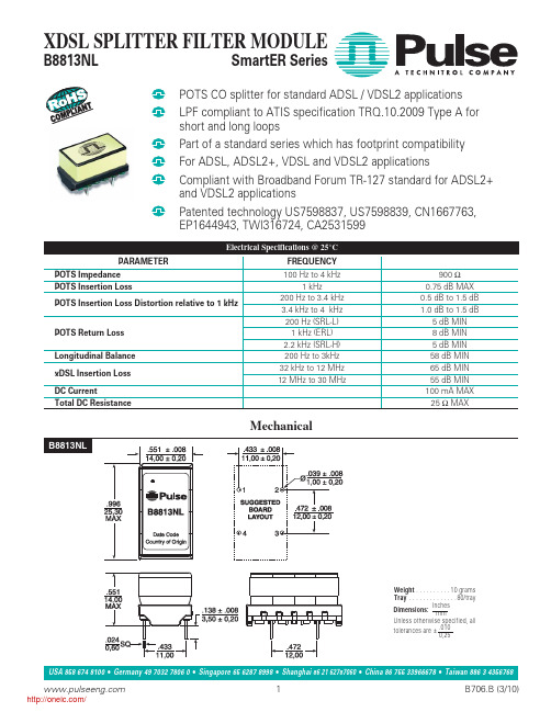
USA 858 674 8100Germany 49 7032 7806 0Singapore 65 6287 8998Shanghai 86 21 62787060China 86 755 33966678Taiwan 886 3 4356768
1
/
© Copyright, 2010. Pulse Engineering, Inc. All rights reserved.
2
/
B706.B (3/10)
分销商库存信息:
PULSE B8813NL
China
Shenzen, PR China 518057
Tel: 49 7032 7806 0 Tel: 86 755 33966678
Tel: 86 21 62787060
Fax: 49 7032 7806 135 Fax: 86 755 33966700
Fax: 86 2162786973
Pulse South Asia 135 Joo Seng Rd. #03-02 PM Industrial Bldg. Singapore 368363
XDSL SPLITTER FILTER MODULE
B8813NL
SmartER Series
POTS CO splitter for standard ADSLto ATIS specification TRQ.10.2009 Type A for short and long loops
Tel: 858 674 8100 Fax: 858 674 8262
Pulse Europe
Pulse China Headquarters Pulse North China
75176B中文资料

75176B中⽂资料PACKAGING INFORMATION Orderable Device Status(1)PackageType PackageDrawingPins PackageQtyEco Plan(2)Lead/Ball Finish MSL Peak Temp(3)SN65176BD ACTIVE SOIC D875Green(RoHS&no Sb/Br)CU NIPDAU Level-1-260C-UNLIMSN65176BDE4ACTIVE SOIC D875Green(RoHS&no Sb/Br)CU NIPDAU Level-1-260C-UNLIMSN65176BDG4ACTIVE SOIC D875Green(RoHS&no Sb/Br)CU NIPDAU Level-1-260C-UNLIMSN65176BDR ACTIVE SOIC D82500Green(RoHS& no Sb/Br)CU NIPDAU Level-1-260C-UNLIMSN65176BDRE4ACTIVE SOIC D82500Green(RoHS& no Sb/Br)CU NIPDAU Level-1-260C-UNLIMSN65176BDRG4ACTIVE SOIC D82500Green(RoHS& no Sb/Br)CU NIPDAU Level-1-260C-UNLIMSN65176BP ACTIVE PDIP P850Pb-Free (RoHS)CU NIPDAU N/A for Pkg TypeSN65176BPE4ACTIVE PDIP P850Pb-Free (RoHS)CU NIPDAU N/A for Pkg TypeSN75176BD ACTIVE SOIC D875Green(RoHS&no Sb/Br)CU NIPDAU Level-1-260C-UNLIMSN75176BDE4ACTIVE SOIC D875Green(RoHS&no Sb/Br)CU NIPDAU Level-1-260C-UNLIMSN75176BDG4ACTIVE SOIC D875Green(RoHS&no Sb/Br)CU NIPDAU Level-1-260C-UNLIMSN75176BDR ACTIVE SOIC D82500Green(RoHS& no Sb/Br)CU NIPDAU Level-1-260C-UNLIMSN75176BDRE4ACTIVE SOIC D82500Green(RoHS&no Sb/Br)CU NIPDAU Level-1-260C-UNLIMSN75176BDRG4ACTIVE SOIC D82500Green(RoHS&no Sb/Br)CU NIPDAU Level-1-260C-UNLIMSN75176BP ACTIVE PDIP P850Pb-Free(RoHS)CU NIPDAU N/A for Pkg TypeSN75176BPE4ACTIVE PDIP P850Pb-Free(RoHS)CU NIPDAU N/A for Pkg TypeSN75176BPSR ACTIVE SO PS82000Green(RoHS&no Sb/Br)CU NIPDAU Level-1-260C-UNLIMSN75176BPSRG4ACTIVE SO PS82000Green(RoHS&no Sb/Br)CU NIPDAU Level-1-260C-UNLIM(1)The marketing status values are defined as follows:ACTIVE:Product device recommended for new designs.LIFEBUY:TI has announced that the device will be discontinued,and a lifetime-buy period is in effect.NRND:Not recommended for new designs.Device is in production to support existing customers,but TI does not recommend using this part in a new design.PREVIEW:Device has been announced but is not in production.Samples may or may not be available.OBSOLETE:TI has discontinued the production of the device.(2)Eco Plan-The planned eco-friendly classification:Pb-Free(RoHS),Pb-Free(RoHS Exempt),or Green(RoHS&no Sb/Br)-please check /doc/7167b986cc22bcd126ff0c93.html /productcontent for the latest availability information and additional product content details.TBD:The Pb-Free/Green conversion plan has not been defined.Pb-Free(RoHS):TI's terms"Lead-Free"or"Pb-Free"mean semiconductor products that are compatible with the current RoHS requirements for all6substances,including the requirement that lead not exceed0.1%by weight in homogeneous materials.Where designed to be soldered at high temperatures,TI Pb-Free products are suitable for use in specified lead-free processes.Pb-Free(RoHS Exempt):This component has a RoHS exemption for either1)lead-based flip-chip solder bumps used between the die andpackage,or2)lead-based die adhesive used between the die and leadframe.The component is otherwise considered Pb-Free(RoHS compatible)as defined above.Green(RoHS&no Sb/Br):TI defines"Green"to mean Pb-Free(RoHS compatible),and free of Bromine(Br)and Antimony(Sb)based flame retardants(Br or Sb do not exceed0.1%by weight in homogeneous material)(3)MSL,Peak Temp.--The Moisture Sensitivity Level rating according to the JEDEC industry standard classifications,and peak soldertemperature.Important Information and Disclaimer:The information provided on this page represents TI's knowledge and belief as of the date that it is provided.TI bases its knowledge and belief on information provided by third parties,and makes no representation or warranty as to the accuracy of such information.Efforts are underway to better integrate information from third parties.TI has taken and continues to take reasonable steps to provide representative and accurate information but may not have conducted destructive testing or chemical analysis on incoming materials and chemicals.TI and TI suppliers consider certain information to be proprietary,and thus CAS numbers and other limited information may not be available for release.In no event shall TI's liability arising out of such information exceed the total purchase price of the TI part(s)at issue in this document sold by TI to Customer on an annual basis.TAPE AND REEL INFORMATIONDevice Package Pins Site ReelDiameter(mm)ReelWidth(mm)A0(mm)B0(mm)K0(mm)P1(mm)W(mm)Pin1QuadrantSN65176BDR D8FMX33012 6.4 5.2 2.1812Q1 SN75176BDR D8FMX33012 6.4 5.2 2.1812Q1 SN75176BPSR PS8MLA330168.2 6.6 2.51216Q1TAPE AND REEL BOX INFORMATIONDevice Package Pins Site Length(mm)Width(mm)Height(mm)SN65176BDR D8FMX338.1340.520.64SN75176BDR D8FMX338.1340.520.64SN75176BPSR PS8MLA342.9336.628.58。
1956467资料

Extract from the onlinecatalogCC 2,5/ 8-GFR-5,08P26THROrder No.: 1956467The illustration shows a left and a right plug, as 8-pos. versionhttp://eshop.phoenixcontact.de/phoenix/treeViewClick.do?UID=1956467Modular headers, right, with screw flange, pin length: 2.6 mm, 5.08mm pitch, 8-pos.http://Please note that the data givenhere has been taken from theonline catalog. For comprehensiveinformation and data, please referto the user documentation. TheGeneral Terms and Conditions ofUse apply to Internet downloads. Technical dataDimensions / positionsPitch 5.08 mmDimension a35.56 mmNumber of positions8Pin dimensions 1 x 1 mmPin spacing 5.08 mmHole diameter 1.4 mmTechnical dataInsulating material group IIIaRated surge voltage (III/3) 4 kVRated surge voltage (III/2) 4 kVRated surge voltage (II/2) 4 kVRated voltage (III/2)320 VRated voltage (II/2)400 VConnection in acc. with standard EN-VDENominal current I N12 ANominal voltage U N250 VMaximum load current12 A (per position)Insulating material LCPInflammability class acc. to UL 94V0Certificates / ApprovalsApproval logoCULNominal voltage U N300 VNominal current I N10 AULNominal voltage U N300 VNominal current I N10 ACertification CUL, ULAccessoriesItem Designation DescriptionGeneral1954362CR-MSTB NAT HT HT coding section, is pushed into the recess on the header beforethe reflow process, made of highly temperature-resistant, beigeinsulating materialMarking1051993B-STIFT Marker pen, for manual labeling of unprinted Zack strips, smear-proof and waterproof, line thickness 0.5 mm0804303SK 5,08/3,8: 0-9Marker card, printed horizontally, self-adhesive, 10-section markerstrip, 12 identical decades marked 0-9, sufficient for 120 terminalblocks0804293SK 5,08/3,8:FORTL.ZAHLEN Marker card, printed horizontally, self-adhesive, 12 identicaldecades marked 1-10, 11-20 etc. up to 91-(99)100, sufficient for120 terminal blocks0805085SK 5,08/3,8:SO Marker card, special printing, self-adhesive, labeled acc. tocustomer requirements, 12 identical marker strips per card, max.25-position labeling per strip, color: white0805412SK 5,08/3,8:UNBEDRUCKT Marker cards, unprinted, with pitch divisions, self-adhesive, 10-section marker strips, 12 strips per card, can be labeled with theM-PENPlug/Adapter1734401CR-MSTB Coding section, inserted into the recess in the header or theinverted plug, red insulating materialDrawingsApplication drawingDrilling diagramDimensioned drawingBottom view, free space for solder paste, 0.5mm deepAddressPHOENIX CONTACT GmbH & Co. KGFlachsmarktstr. 832825 Blomberg,GermanyPhone +49 5235 3 00Fax +49 5235 3 41200http://www.phoenixcontact.de© 2008 Phoenix ContactTechnical modifications reserved;。
1-1393662-0资料
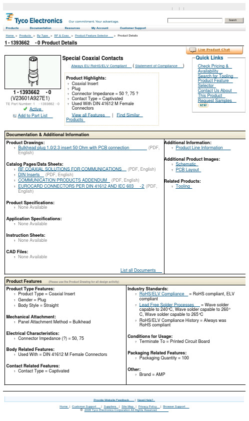
1-1393662-0 Product DetailsHome | Customer Support | Suppliers | Site Map | Privacy Policy | Browser Support© 2008 Tyco Electronics Corporation All Rights Reserved SearchProducts Documentation Resources My Account Customer Support Home > Products > By Type > RF & Coax > Product Feature Selector > Product Details1-1393662-0 (V23601A927E1)TE Part Number: 1-1393662-0ActiveAdd to Part List Special Coaxial ContactsAlways EU RoHS/ELV Compliant (Statement of Compliance)Product Highlights:?Coaxial Insert?Plug?Connector Impedance = 50 ?, 75 ??Contact Type = Captivated?Used With DIN 41612 M FemaleConnectorsView all Features | Find SimilarProductsCheck Pricing &AvailabilitySearch for ToolingProduct FeatureSelectorContact Us AboutThis ProductRequest SamplesQuick LinksDocumentation & Additional InformationProduct Drawings:?Bulkhead plug 1.0/2.3 insert 50 Ohm with PCB connection(PDF, English)Catalog Pages/Data Sheets:?RF COAXIAL SOLUTIONS FOR COMMUNICATIONS(PDF, English) ?DIN Inserts(PDF, English)?COMMUNICATION PRODUCTS ADDENDUM(PDF, English)?EUROCARD CONNECTORS PER DIN 41612 AND IEC 603-2(PDF, English)Product Specifications:?None AvailableApplication Specifications:?None AvailableInstruction Sheets:?None AvailableCAD Files:?None AvailableList all Documents Additional Information:?Product Line InformationAdditional Product Images: ?Schematic?PCB LayoutRelated Products:?ToolingProduct Features (Please use the Product Drawing for all design activity)Product Type Features:?Product Type = Coaxial Insert?Gender = Plug?Body Style = StraightMechanical Attachment:?Panel Attachment Method = BulkheadElectrical Characteristics:?Connector Impedance (?) = 50, 75Body Related Features:?Used With = DIN 41612 M Female ConnectorsContact Related Features:?Contact Type = Captivated Industry Standards:?RoHS/ELV Compliance = RoHS compliant, ELVcompliant?Lead Free Solder Processes = Wave soldercapable to 240°C, Wave solder capable to 260°C, Wave solder capable to 265°C?RoHS/ELV Compliance History = Always wasRoHS compliantConditions for Usage:?Terminate To = Printed Circuit BoardPackaging Related Features:?Packaging Quantity = 100Other:?Brand = AMPProvide Website Feedback | Need Help?。
1873168资料

Extract from the onlinecatalogFKC 2,5/13-ST-5,08Order No.: 1873168The figure shows a 10-position version of the producthttp://eshop.phoenixcontact.de/phoenix/treeViewClick.do?UID=1873168Plug component, nominal current: 12 A, rated voltage: 250 V, pitch: 5.08 mm, no. of positions: 13, type of connection: Spring-cage connectionhttp://Please note that the data givenhere has been taken from theonline catalog. For comprehensiveinformation and data, please referto the user documentation. TheGeneral Terms and Conditions ofUse apply to Internet downloads. Technical dataDimensions / positionsPitch 5.08 mmDimension a60.96 mmNumber of positions13Technical dataInsulating material group IRated surge voltage (III/3) 4 kV Rated surge voltage (III/2) 4 kV Rated surge voltage (II/2) 4 kV Rated voltage (III/2)320 V Rated voltage (II/2)630 V Connection in acc. with standard EN-VDE Nominal current I N12 A Nominal voltage U N250 V Nominal cross section 2.5 mm2 Maximum load current12 A Insulating material PA Inflammability class acc. to UL 94V0 Internal cylindrical gage A2 Stripping length10 mmConnection dataConductor cross section solid min.0.2 mm2 Conductor cross section solid max. 2.5 mm2 Conductor cross section stranded min.0.2 mm2 Conductor cross section stranded max. 2.5 mm2 Conductor cross section stranded, with ferrule0.25 mm2 without plastic sleeve min.Conductor cross section stranded, with ferrule2.5 mm2 without plastic sleeve max.Conductor cross section stranded, with ferrule0.25 mm2 with plastic sleeve min.Conductor cross section stranded, with ferrule2.5 mm2 with plastic sleeve max.Conductor cross section AWG/kcmil min.24 Conductor cross section AWG/kcmil max122 conductors with same cross section, stranded,0.5 mm2 TWIN ferrules with plastic sleeve, min.2 conductors with same cross section, stranded,1.5 mm2 TWIN ferrules with plastic sleeve, max.Certificates / ApprovalsApproval logoCULNominal voltage U N300 VNominal current I N10 AAWG/kcmil26-12ULNominal voltage U N300 VNominal current I N10 AAWG/kcmil26-12Certification CB, CUL, GOST, UL, VDE-PZIAccessoriesItem Designation DescriptionAssembly1876880STZ 8-FKC-5,08Strain relief for snapping into the latching chambers of the plugcomponents, 8-pos.1876877STZ 4-FKC-5,08Strain relief for snapping into the latching chambers of the plugs,4-pos.Marking1051993B-STIFT Marker pen, for manual labeling of unprinted Zack strips, smear-proof and waterproof, line thickness 0.5 mm0804293SK 5,08/3,8:FORTL.ZAHLEN Marker card, printed horizontally, self-adhesive, 12 identicaldecades marked 1-10, 11-20 etc. up to 91-(99)100, sufficient for120 terminal blocks0805085SK 5,08/3,8:SO Marker card, special printing, self-adhesive, labeled acc. tocustomer requirements, 12 identical marker strips per card, max.25-position labeling per strip, color: white0805412SK 5,08/3,8:UNBEDRUCKT Marker cards, unprinted, with pitch divisions, self-adhesive, 10-section marker strips, 12 strips per card, can be labeled with theM-PENPlug/Adapter1734634CP-MSTB Coding profile, is inserted into the slot on the plug or invertedheader, red insulating material0201689MPS-IH BU Insulating sleeve (blue), for MPS metal part to be orderedseparately (0201744)0201702MPS-IH GN Insulating sleeve (green), for MPS metal part to be orderedseparately (0201744)0201676MPS-IH RD Insulating sleeve (red), for MPS metal part to be orderedseparately (0201744)0201663MPS-IH WH Insulating sleeve (white), for MPS metal part to be orderedseparately (0201744)0201744MPS-MT Test plug, consisting of: Metal part for 2.3 mm diameter sockethole0201647RPS Reducing plug, for transition from 4 mm diameter test plug socket,insulation: grayTools1205053SZS 0,6X3,5Screwdriver, bladed, matches all screw terminal blocks up to 4.0mm² connection cross section, blade: 0.6 x 3.5 mm, without VDEapprovalAdditional productsItem Designation DescriptionGeneral1823956ICC 2,5/13-STZ-5,08Plug component, nominal current: 12 A, rated voltage: 250 V,pitch: 5.08 mm, no. of positions: 13, type of connection: Crimpconnection1762473MDSTB 2,5/13-G1-5,08Header, nominal current: 10 A, rated voltage: 250 V, pitch: 5.08mm, no. of positions: 13, mounting: Soldering1762619MDSTBV 2,5/13-G1-5,08Header, nominal current: 10 A, rated voltage: 250 V, pitch: 5.08mm, no. of positions: 13, mounting: Soldering1770821MSTB 2,5/13-G-5,08-LA Header, nominal current: 12 A, rated voltage: 250 V, pitch: 5.08mm, no. of positions: 13, mounting: Soldering1788839MSTBVK 2,5/13-G-5,08Header, nominal current: 12 A, rated voltage: 320 V, pitch: 5.08mm, no. of positions: 13, mounting: Mounting rail1788648MVSTBU 2,5/13-GB-5,08Header, nominal current: 12 A, rated voltage: 320 V, pitch: 5.08mm, no. of positions: 13, mounting: Direct mounting1769573SMSTB 2,5/13-G-5,08Header, nominal current: 12 A, rated voltage: 250 V, pitch: 5.08mm, no. of positions: 13, mounting: Soldering1767481SMSTBA 2,5/13-G-5,08Header, nominal current: 12 A, rated voltage: 250 V, pitch: 5.08mm, no. of positions: 13, mounting: Soldering3002034UK 3-MSTB-5,08Modular terminal blocks with plug entry, cross section: 0.2 - 2.5mm², AWG: 30 - 12, width: 5.1 mm, color: gray3002076UK 3-MVSTB-5,08Modular terminal blocks with plug entry, cross section: 0.2 - 2.5mm², AWG: 26 - 12, width: 5.1 mm, color: gray3002102UK 3-MVSTB-5,08-LA 24RD Modular terminal block with plug entry, nominal current: 12 A,rated voltage: 320 V, pitch: 5.08 mm, no. of positions: 1, mounting:mounting rail, with red light indicator, voltage light indicator: 24 VAC/DC, current light indicator: 3.3 mA3002063UK 3-MVSTB-5,08/EK Modular terminal blocks with plug entry, cross section: 0.2-2.5mm², AWG: 26-12, width: 5.1 mm, color: blue3002131UK 3D-MSTBV-5,08Modular terminal blocks with vertical plug entry, cross section: 0.2- 2.5 mm, AWG: 30 - 12, width: 5.1 mm, color: gray3002144UK 3D-MSTBV-5,08-LA 24RD Modular terminal block with vertical plug entry, color: Gray, withred light indicator, voltage light indicator: 24 V AC/DC, current lightindicator: 3.3 mA3002173UK 3D-MSTBV-5,08/EK Modular terminal blocks with plug entry, cross section: 0.2 - 2.5mm², AWG: 30 - 12, width: 5.1 mm, color: blue2770888UKK 3-MSTB-5,08Modular terminal blocks with 2 horizontal plug entries, crosssection: 0.2 - 2.5 mm, AWG: 30 - 12, width: 5.1 mm, color: gray 1876615UKK 3-MSTB-5,08-PE Ground terminal block, with 2 horizontal plug entries, nominalcurrent: 12 A, rated voltage: 320 V, pitch: 5.08 mm, no. ofpositions: 1, mounting: mounting rail.2770846UKK 3-MSTBVH-5,08Modular terminal blocks with vertical and horizontal plug entry,cross section: 0.2 - 2.5 mm, AWG: 30 - 12, width: 5.1 mm, color:gray1788224UMSTBVK 2,5/13-G-5,08Header, nominal current: 12 A, rated voltage: 320 V, pitch: 5.08mm, no. of positions: 13, mounting: Mounting rail1873016ZFKK 1,5-MSTBV-5,08Modular terminal blocks with plug entry, cross section: 0.2 - 1.5mm², width: 5.1 mm, color: grayDrawingsDimensioned drawingAddressPHOENIX CONTACT GmbH & Co. KGFlachsmarktstr. 832825 Blomberg,GermanyPhone +49 5235 3 00Fax +49 5235 3 41200http://www.phoenixcontact.de© 2008 Phoenix ContactTechnical modifications reserved;。
1789333资料
© 2008 Phoenix Contact Technical modifications reserved;
PHOENIX CONTACT GmbH & Co. KG http://www.phoenixcontact.de
Page 3 / 3 Mar 2, 2008
Page 1 / 3 Mar 2, 2008
元器件交易网
FFKDSA1/H-2,54-10 Order No.: 1789333
http://eshop.phoenixcontact.de/phoenix/treeViewClick.do?UID=1789333
Nominal current IN AWG/kcmil UL Nominal voltage UN Nominal current IN AWG/kcmil Certification
Approval logo
CSA Nominal voltage UN Nominal current IN AWG/kcmil CUL Nominal voltage UN 150 V 150 V 6A 20
PHOENIX CONTACT GmbH & Co. KG http://www.phoenixcontact.de
6A 26-20
150 V 6A 26-20 CSA, CUL, UL
PHOENIX CONTACT GmbH & Co. KG http://www.phoenixcontact.de
Page 2 / 3 Mar 2, 2008
元器件交易网
FFKDSA1/H-2,54-10 Order No.: 1789333
元器件交易网
Extract from the online catalog
1827114资料

Extract from the onlinecatalogMCVW 1,5/16-ST-3,81Order No.: 1827114The figure shows a 10-position version of the producthttp://eshop.phoenixcontact.de/phoenix/treeViewClick.do?UID=1827114Plug component, nominal current: 8 A, rated voltage: 160 V, pitch: 3.81 mm, no. of positions: 16, type of connection: Screw connectionhttp://Please note that the data givenhere has been taken from theonline catalog. For comprehensiveinformation and data, please referto the user documentation. TheGeneral Terms and Conditions ofUse apply to Internet downloads. Technical dataDimensions / positionsHeight12.5 mmPitch 3.81 mmDimension a57.15 mmNumber of positions16Screw thread M 2Tightening torque, min0.22 NmTechnical dataInsulating material group IRated surge voltage (III/3) 2.5 kVRated surge voltage (III/2) 2.5 kVRated surge voltage (II/2) 2.5 kVRated voltage (III/2)160 VRated voltage (II/2)320 VConnection in acc. with standard EN-VDENominal current I N8 ANominal voltage U N160 VNominal cross section 1.5 mm2Maximum load current8 A (with 1.5 mm2 conductor cross section) Insulating material PAInflammability class acc. to UL 94V0Internal cylindrical gage A1Stripping length7 mmConnection dataConductor cross section solid min.0.14 mm2Conductor cross section solid max. 1.5 mm2Conductor cross section stranded min.0.14 mm2Conductor cross section stranded max. 1.5 mm2Conductor cross section stranded, with ferrule0.25 mm2without plastic sleeve min.Conductor cross section stranded, with ferrule1.5 mm2without plastic sleeve max.Conductor cross section stranded, with ferrule0.25 mm2with plastic sleeve min.Conductor cross section stranded, with ferrule0.5 mm2with plastic sleeve max.Conductor cross section AWG/kcmil min.28Conductor cross section AWG/kcmil max162 conductors with same cross section, solid min.0.08 mm22 conductors with same cross section, solid max.0.5 mm22 conductors with same cross section, stranded min.0.08 mm 22 conductors with same cross section, stranded max.0.75 mm 22 conductors with same cross section, stranded,ferrules without plastic sleeve, min.0.25 mm 22 conductors with same cross section, stranded,ferrules without plastic sleeve, max.0.34 mm 22 conductors with same cross section, stranded,TWIN ferrules with plastic sleeve, min.0.5 mm 22 conductors with same cross section, stranded,TWIN ferrules with plastic sleeve, max.0.5 mm2Certificates / ApprovalsCSANominal voltage U N 300 V Nominal current I N 8 A AWG/kcmil 28-16CULNominal voltage U N 300 V Nominal current I N 8 A AWG/kcmil 30-14ULNominal voltage U N 300 V Nominal current I N 8 A AWG/kcmil 30-14Certification CB, CSA, CUL, GOST, UL, VDE-PZIAccessories Item Designation DescriptionMarking 1051993B-STIFTMarker pen, for manual labeling of unprinted Zack strips, smear-proof and waterproof, line thickness 0.5 mm0804109SK 3,81/2,8:FORTL.ZAHLEN Marker card, printed horizontally, self-adhesive, 10-section markerstrip, 14 identical decades marked 1-10, 11-20 etc. up to 91-(99)100, sufficient for 140 terminal blocks0805056SK 3,81/2,8:SO Marker card, special printing, self-adhesive, labeled acc. tocustomer requirements, 14 identical marker strips per card, max.25-position labeling per strip, color: White0803883SK U/2,8 WH:UNBEDRUCKT Unprinted marker cards, DIN A4 format, pitch as desired, self-adhesive, with 50 stamped marker strips, 185 mm strip length, canbe labeled with the CMS system or manually with the M-PENTools1205037SZS 0,4X2,5Screwdriver, bladed, matches all screw terminal blocks up to 1.5mm² connection cross section, blade: 0.4 x 2.5 mmAdditional productsItem Designation DescriptionGeneral1897940EMC 1,5/16-G-3,81Header, nominal current: 8 A, rated voltage: 160 V, pitch: 3.81mm, no. of positions: 16, mounting: Press in1860786EMCV 1,5/16-G-3,81Header, nominal current: 8 A, rated voltage: 160 V, pitch: 3.81mm, no. of positions: 16, mounting: Press in1858028IMC 1,5/16-ST-3,81Plug component, nominal current: 8 A, rated voltage: 160 V,pitch: 3.81 mm, no. of positions: 16, type of connection: Screwconnection1803413MC 1,5/16-G-3,81Header, nominal current: 8 A, rated voltage: 160 V, pitch: 3.81mm, no. of positions: 16, mounting: Soldering1830091MCD 1,5/16-G-3,81Header, nominal current: 8 A, rated voltage: 160 V, pitch: 3.81mm, no. of positions: 16, mounting: Soldering1843211MCD 1,5/16-G1-3,81Header, nominal current: 8 A, rated voltage: 160 V, pitch: 3.81mm, no. of positions: 16, mounting: Soldering1830541MCDV 1,5/16-G-3,81Header, nominal current: 8 A, rated voltage: 160 V, pitch: 3.81mm, no. of positions: 16, mounting: Soldering1847877MCDV 1,5/16-G1-3,81Header, nominal current: 8 A, rated voltage: 160 V, pitch: 3.81mm, no. of positions: 16, mounting: Soldering1803565MCV 1,5/16-G-3,81Header, nominal current: 8 A, rated voltage: 160 V, pitch: 3.81mm, no. of positions: 16, mounting: Soldering1837573MCVDU 1,5/16-G-3,81Header, nominal current: 8 A, rated voltage: 160 V, pitch: 3.81mm, no. of positions: 16, mounting: Soldering1832879MCVK 1,5/16-G-3,81Header, nominal current: 8 A, rated voltage: 160 V, pitch: 3.81mm, no. of positions: 16, mounting: Mounting rail1827415SMC 1,5/16-G-3,81Header, nominal current: 8 A, rated voltage: 160 V, pitch: 3.81mm, no. of positions: 16, mounting: SolderingDrawings Dimensioned drawingAddressPHOENIX CONTACT GmbH & Co. KGFlachsmarktstr. 832825 Blomberg,GermanyPhone +49 5235 3 00Fax +49 5235 3 41200http://www.phoenixcontact.de© 2008 Phoenix ContactTechnical modifications reserved;。
2SD1823资料
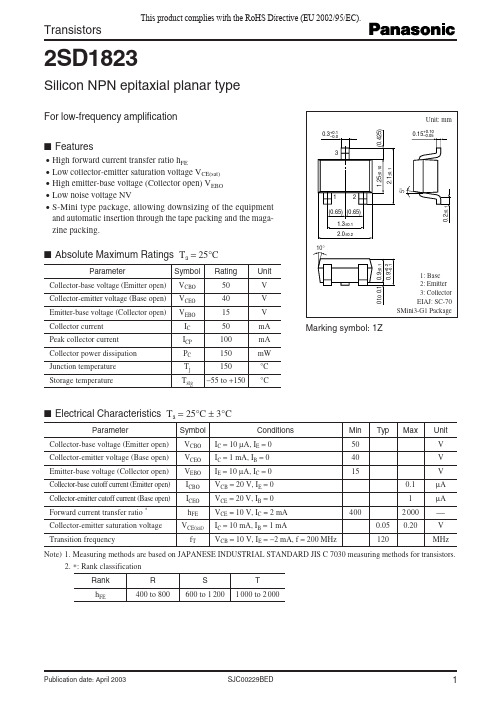
Min 50 40 15
Typ
0 to 0.1
Max
Unit V V V µA µA V MHz
0.1 1 400 0.05 120 2 000 0.20
Collector-emitter saturation voltage Transition frequency
Note) 1. Measuring methods are based on JAPANESE INDUSTRIAL STANDARD JIS C 7030 measuring methods for transistors. 2. *: Rank classification Rank hFE R 400 to 800 S 600 to 1 200 T 1 000 to 2 000
0.2±0.1
Publication date: April 2003
SJC00229BED
1
This product complies with the RoHS Directive (EU 2002/95/EC).
2SD1823
PC Ta
200
160 Ta = 25°C
IC VCE
120
(1) If any of the products or technical information described in this book is to be exported or provided to non-residents, the laws and regulations of the exporting country, especially, those with regard to security export control, must be observed. (2) The technical information described in this book is intended only to show the main characteristics and application circuit examples of the products, and no license is granted under any intellectual property right or other right owned by our company or any other company. Therefore, no responsibility is assumed by our company as to the infringement upon any such right owned by any other company which may arise as a result of the use of technical information described in this book. (3) The products described in this book are intended to be used for standard applications or general electronic equipment (such as office equipment, communications equipment, measuring instruments and household appliances). Consult our sales staff in advance for information on the following applications: – Special applications (such as for airplanes, aerospace, automobiles, traffic control equipment, combustion equipment, life support systems and safety devices) in which exceptional quality and reliability are required, or if the failure or malfunction of the products may directly jeopardize life or harm the human body. – Any applications other than the standard applications intended. (4) The products and product specifications described in this book are subject to change without notice for modification and/or improvement. At the final stage of your design, purchasing, or use of the products, therefore, ask for the most up-to-date Product Standards in advance to make sure that the latest specifications satisfy your requirements. (5) When designing your equipment, comply with the range of absolute maximum rating and the guaranteed operating conditions (operating power supply voltage and operating environment etc.). Especially, please be careful not to exceed the range of absolute maximum rating on the transient state, such as power-on, power-off and mode-switching. Otherwise, we will not be liable for any defect which may arise later in your equipment. Even when the products are used within the guaranteed values, take into the consideration of incidence of break down and failure mode, possible to occur to semiconductor products. Measures on the systems such as redundant design, arresting the spread of fire or preventing glitch are recommended in order to prevent physical injury, fire, social damages, for example, by using the products. (6) Comply with the instructions for use in order to prevent breakdown and characteristics change due to external factors (ESD, EOS, thermal stress and mechanical stress) at the time of handling, mounting or at customer's process. When using products for which damp-proof packing is required, satisfy the conditions, such as shelf life and the elapsed time since first opening the packages. (7) This book may be not reprinted or reproduced whether wholly or partially, without the prior written permission of Matsushita Electric Industrial Co., Ltd.
- 1、下载文档前请自行甄别文档内容的完整性,平台不提供额外的编辑、内容补充、找答案等附加服务。
- 2、"仅部分预览"的文档,不可在线预览部分如存在完整性等问题,可反馈申请退款(可完整预览的文档不适用该条件!)。
- 3、如文档侵犯您的权益,请联系客服反馈,我们会尽快为您处理(人工客服工作时间:9:00-18:30)。
Extract from the onlinecatalogICC 2,5/ 8-STZFD-5,08Order No.: 1823671The illustration shows a 15-position versionhttp://eshop.phoenixcontact.de/phoenix/treeViewClick.do?UID=1823671Plug component, nominal current: 12 A, rated voltage: 250 V, pitch:5.08 mm, no. of positions: 8, type of connection: Crimp connectionhttp://Please note that the data givenhere has been taken from theonline catalog. For comprehensiveinformation and data, please referto the user documentation. TheGeneral Terms and Conditions ofUse apply to Internet downloads. Technical dataDimensions / positionsPitch 5.08 mmNumber of positions8Technical dataInsulating material group IRated surge voltage (III/3) 4 kVRated surge voltage (III/2) 4 kVRated surge voltage (II/2) 4 kVRated voltage (III/2)320 VRated voltage (II/2)630 VConnection in acc. with standard EN-VDENominal current I N12 ANominal voltage U N250 VNominal cross section 2.5 mm2Insulating material PAInflammability class acc. to UL 94V0Connection dataConductor cross section stranded min.0.5 mm2Conductor cross section stranded max. 2.5 mm2Conductor cross section AWG/kcmil min.20Conductor cross section AWG/kcmil max14Certificates / ApprovalsApproval logoCSANominal voltage U N300 VNominal current I N10 AAWG/kcmil20-14CULNominal voltage U N300 VNominal current I N10 AAWG/kcmil20-14ULNominal voltage U N300 VNominal current I N10 AAWG/kcmil20-14Certification CB, CSA, CUL, UL, VDE-PZIAccessoriesItem Designation DescriptionMarking0804280SK 5,08/2,8:FORTL.ZAHLEN Marker card, printed horizontally, self-adhesive, 10-section markerstrip, 14 identical decades marked 1-10, 11-20 etc. up to 91-(99)100, sufficient for 140 terminal blocksPlug/Adapter3190577ICC-MT 0,5-1,0Module male contact, is inserted into the ICC connector shell afterthe conductor has been crimped, for conductors from 0.5-1.0 mm²3190603ICC-MT 0,5-1,0 BA Module male contact, is inserted into the ICC connector shell afterthe conductor has been crimped, for conductors from 0.5-1.0 mm²,ribbon contact3190580ICC-MT 1,5-2,5Module male contact, is inserted into the ICC connector shell afterthe conductor has been crimped, for conductors from 1.5-2.5 mm²3190593ICC-MT 1,5-2,5 BA Module male contact, is inserted into the ICC connector shell afterthe conductor has been crimped, for conductors from 1.5-2.5 mm²,ribbon contact1810529STZ 2-MSTBC-5,08Strain relief for snapping into the latching chambers of the plugcomponents, 2-pos., labeling with ZB 61810532STZ 4-MSTBC-5,08Strain relief for snapping into the latching chambers of the plugcomponents, 4-pos., labeling with ZB 61810516STZ 8-MSTBC-5,08Strain relief for snapping into the latching chambers of the plugcomponents, 8-pos., labeling with ZB 61810503STZ 12-MSTBC-5,08Strain relief for snapping into the latching chambers of the plugcomponents, 12-pos., labeling with ZB 6Tools1204038CRIMPFOX MT 2,5Crimping pliers, for crimping conductors to the module femalecontacts STG-MTN, crimp range: 0.5-2.5 mm², AWG: 20-14 1205037SZS 0,4X2,5Screwdriver, bladed, matches all screw terminal blocks up to 1.5mm² connection cross section, blade: 0.4 x 2.5 mmAdditional productsItem Designation DescriptionGeneral1873265FKC 2,5/ 8-STF-5,08Plug with screw flange, nominal current: 12 A, rated voltage: 250V, pitch: 5.08 mm, no. of positions: 8, type of connection: Spring-cage connection1902369FKCT 2,5/ 8-STF-5,08Plug component, nominal current: 12 A, rated voltage: 250 V,pitch: 5.08 mm, no. of positions: 8, type of connection: Spring-cage connection1874167FKCVR 2,5/ 8-STF-5,08Plug component, nominal current: 12 A, rated voltage: 250 V,pitch: 5.08 mm, no. of positions: 8, type of connection: Spring-cage connection1873867FKCVW 2,5/ 8-STF-5,08Plug component, nominal current: 12 A, rated voltage: 250 V,pitch: 5.08 mm, no. of positions: 8, type of connection: Spring-cage connection1777798FRONT-MSTB 2,5/ 8-STF-5,08Plug with screw flange, nominal current: 12 A, rated voltage: 250V, pitch: 5,08 mm, no. of positions: 8, type of connection: Screwconnection1778043MSTB 2,5/ 8-STF-5,08Plug component, nominal current: 12 A, rated voltage: 250 V,pitch: 5.08 mm, no. of positions: 8, type of connection: Screwconnection1809792MSTBC 2,5/ 8-STZF-5,08Plug component, nominal current: 12 A, rated voltage: 320 V,pitch: 5.08 mm, no. of positions: 8, type of connection: Crimpconnection1804661MSTBT 2,5/ 8-STF-5,08Plug with T-shape and screw flange, nominal current: 12 A,rated voltage: 250 V, pitch: 5.08 mm, no. of positions: 8, type ofconnection: Screw connection1835151MVSTBR 2,5/ 8-STF-5,08Plug with screw flange, nominal current: 12 A, rated voltage: 250V, pitch: 5,08 mm, no. of positions: 8, type of connection: Screwconnection1834961MVSTBW 2,5/ 8-STF-5,08Plug component, nominal current: 12 A, rated voltage: 250 V,pitch: 5.08 mm, no. of positions: 8, type of connection: Screwconnection1918159QC 0,75/ 8-STF-5,08Plug components, 5.08 mm pitch, color: green, no. of positions 8,dimension a 35.56 mm1883417QC 1/ 8-STF-5,08Plug, nominal current: 10 A, rated voltage: 500 V, pitch: 5.08mm, number of positions: 8, connection method: Insulationdisplacement connection QUICKON1853162TMSTBP 2,5/ 8-STF-5,08Plug component, nominal current: 12 A, rated voltage: 250 V,pitch: 5.08 mm, no. of positions: 8, type of connection: ScrewconnectionDrawingsDrilling diagramDimensioned drawingAddressPHOENIX CONTACT GmbH & Co. KGFlachsmarktstr. 832825 Blomberg,GermanyPhone +49 5235 3 00Fax +49 5235 3 41200http://www.phoenixcontact.de© 2008 Phoenix ContactTechnical modifications reserved;。
