RSC Adv.:具有高光学透明度、良好机械强度和有效PM2.5捕获能力的图案化纳米纤维空气过滤器
雷达科技:LS7002 全球最先进的闪电检测系统说明书
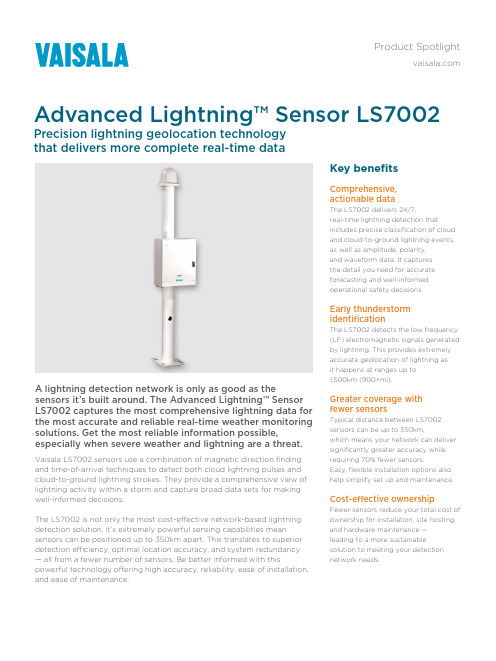
Key benefitsComprehensive, actionable dataThe LS7002 delivers 24/7,real-time lightning detection thatincludes precise classification of cloud and cloud-to-ground lightning events, as well as amplitude, polarity, and waveform data. It captures the detail you need for accurate forecasting and well-informed operational safety decisions.Early thunderstorm identificationThe LS7002 detects the low frequency (LF) electromagnetic signals generated by lightning. This provides extremely accurate geolocation of lightning as it happens at ranges up to 1,500km (900+mi).Greater coverage with fewer sensorsTypical distance between LS7002 sensors can be up to 350km,which means your network can deliver significantly greater accuracy while requiring 70% fewer sensors.Easy, flexible installation options also help simplify set up and maintenance.Cost-effective ownershipFewer sensors reduce your total cost of ownership for installation, site hosting, and hardware maintenance — leading to a more sustainablesolution to meeting your detection network needs.Vaisala LS7002 sensors use a combination of magnetic direction finding and time-of-arrival techniques to detect both cloud lightning pulses and cloud-to-ground lightning strokes. They provide a comprehensive view of lightning activity within a storm and capture broad data sets for making well-informed decisions.The LS7002 is not only the most cost-effective network-based lightning detection solution, it’s extremely powerful sensing capabilities meansensors can be positioned up to 350km apart. This translates to superior detection efficiency, optimal location accuracy, and system redundancy — all from a fewer number of sensors. Be better informed with thispowerful technology offering high accuracy, reliability, ease of installation, and ease of maintenance.A lightning detection network is only as good as thesensors it’s built around. The Advanced Lightning™ Sensor LS7002 captures the most comprehensive lightning data for the most accurate and reliable real-time weather monitoring solutions. Get the most reliable information possible,especially when severe weather and lightning are a threat.Advanced Lightning™ Sensor LS7002Precision lightning geolocation technologythat delivers more complete real-time dataProduct SpotlightLS7002 at a glanceApplications• Establishing early warning systems to alert people about hazardous weather conditions and potential for lightning threat.• Providing critical information for utility companies and telecoms for storm preparation and system reliability support.• Generating reliable data for meteorological modeling,hazardous weather forecasting, and emergency management.• Supporting operational safety while maximizing productivity for aviation and maritime operations.• Prioritizing resource deployment in the first moments of incident to speed containment and limit property damage.Key featuresComprehensive lightning detection that includes type classification, amplitude, polarity, location, and waveform features.Exceptional data capture with up to 95% network detection efficiency for cloud-to-ground lightning and better than 50% network detection efficiency for cloud lightning.Real-time data delivery with minimized latency and raw sensor data generation capabilities to support offline reprocessing and archiving needs.At-sensor data buffering for data confidence and redundancy in case of communication failure between sensor and central processor.Why Vaisala?The industrystandard in global lightning detectionFor decades, meteorological agencies around the worldhave relied on Vaisala lightning detection technology to improve forecasts and weather services for their countries. Vaisala delivers the most accurate real-time and historical lightning data in the world with more than 90 lightning networks in 45 countries. Our technology is trusted by Armed Forces worldwide, the NationalWeather Service, the Federal Aviation Administration,commercial safety operations, and power utility companies across the planet.Support to count onLook to Vaisala for dependable support, project capabilities, and training so you can get the most from your system. With decades ofexperience providing the best technologies and the finest support, Vaisala’s philosophy of partnership is unmatched in the industry.Trusted weather observations for a sustainable future/meteorologyScan the code formore informationRef. B212227EN-A ©Vaisala 2020This material is subject to copyright protection, with all copyrights retained by Vaisala and its individual partners. All rights reserved. Any logos and/or product names are trademarks of Vaisala or its individual partners. The reproduction, transfer, distribution or storage of information contained in this brochure in any form without the prior written consent of Vaisala is strictly prohibited. All specifications — technical included — are subject to change without notice.。
高频实力强劲,Advanced Amplifiers Solid State RF Amplifie

Instruction Manual Including Quick Start GuideAdvanced AmplifiersSolid State RF Amplifier SystemAA-1M6G-301 MHz - 6.0 GHz, 30 Watt, 45dB MinTable of ContentsSAFETY INSTRUCTIONS (3)SPECIFICATIONS (4)ELECTRICAL SPECIFICATIONS: 50Ω, 25°C (4)ENVIRONMENTAL CHARACTERISTICS (4)MECHANICAL SPECIFICATIONS (4)OPERATING INSTRUCTIONS & GENERAL INFORMATION (5)INTRODUCTION (5)INCOMING INSPECTION (5)RF & AC CABLE CONNECTION (5)RF TURN ON PROCEDURE (5)RF TURN OFF PROCEDURE (5)DECLARATION OF CE CONFORMITY (6)LIMITED WARRANTY (6)CONTACT INFORMATION (6)FRONT & REAR PANEL DESCRIPTIONS (7)FRONT PANEL VIEW (7)REAR PANEL VIEW (8)SYSTEM OUTLINE VIEW (9)SAFETY INSTRUCTIONSBEFORE USING THIS EQUIPMENTRead this manual and become familiar with safety markings and instructions.Inspect unit for any sign of external damage. Do not use this equipment if there is physical damage or missing parts. Verify the input AC voltage to the main power supply.For a system with a digital controller option – DO NOT USE OR CONNECT a PoE enabled ethernet switch to a system. Our digital controller does not support PoE connection and will cause permanent damages to a controller unit. INTENDED USEThis product is intended for general laboratory use in a wide variety of industrial and scientific applications.RF OUTPUT LOAD & PROPER GROUNDING REQUIREDThe RF output connector must be connected to a load before the AC switch is turned on.AC & RF power must be off before disconnecting the output load or other components.The main power source to the equipment must have an uninterrupted safety ground that has sufficient size to the power cord.REPAIR & MAINTENANCEAll repair or maintenance work must be performed by a factory authorized technician in order to extend the operating life of this equipment and not to void any outstanding warranty.FORCED AIR COOLINGThis equipment requires forced air cooling. All air inlets and outlets must be cleared and free of blocking at all time. Insufficient air flow will result in damaged equipment.SAFETY SYMBOLSThis symbol is marked on the equipment when it is necessary for the user to refer to the manual forimportant safety information. This symbol is indicated in the Table of Contents to assist in locatingpertinent information.Dangerous voltages are present. Use extreme care.The caution symbol denotes a potential hazard. Attention must be given to the statement to preventdamage, destruction or harm.This symbol indicates protective earth terminal.SPECIFICATIONSELECTRICAL SPECIFICATIONS: 50Ω, 25°CParameter Specification NotesBand A BOperating Frequency Band 1 - 1000 MHz 1 - 6 GHz Band switching @ 15 mS Max Power Output @ Psat30 Watt Min / 50 Watt Typ CW or Pulse Power Gain45 dB Min0dBm or less for rated Pout Power Gain Flatness 4.0 dB p-p Max Constant input power Gain Adjustment Range20 dB Min Local or remote Input Return Loss-10 dB Max2-Tone Intermodulation (IMD)-30 dBc Typ35dBm/Tone, Δ = 1MHz Harmonics<-20 dBc Typ At rated Pout Spurious-60 dBc Max Non-harmonics Operating Voltage100 - 240 VAC47 - 63 HzPower Consumption500 Watt Max At rated PoutInput Power Protection+10 dBm Max1Load VSWR Protection 6 : 1: Max2Foldback @ preset limit Sample Port (optional)-40 dB N-Female1 Units with optional digital monitor and control, for basic units <10 Sec without damage2 Units with optional digital monitor and control, for basic units <1 minute at rated PoutENVIRONMENTAL CHARACTERISTICSParameter Specification Notes Operating Ambient Temperature0 to +50 °CStorage Temperature-40 to +85 °CRelative Humidity up to 95 %Non-condensing Altitude3000 metersShock & Vibration Normal transport3MECHANICAL SPECIFICATIONSParameter Specification Notes Dimensions W x H x D430 x 88 x 700 mm2U, excluding handles Weight12 Kg.RF Connectors Input/Output/Sample N-Female Front or rear panel Interface Connector9-Pin D-Sub Rear panelAC Power IEC 60320-C14Or equivalent Cooling Built in Fan Cooling Variable speedOPTIONAL: Digital Monitor & Control (DMC) FWD, REV, VSWR, GAIN, ALC, V & I, TEMP, Optional Safety Interlock (INT)Ethernet RJ-45 TCP/IP, RS422/485, USBOptional GPIB InterfaceOpen=STBY/Short=RFONIEEE rear panelBNC-F rear panelOPERATING INSTRUCTIONS & GENERAL INFORMATION INTRODUCTIONAdvanced Amplifiers is an amplifier equipment and services company supporting commercial and government organizations worldwide.Headquartered in San Diego, California, the company utilizes its global network of resources to effectively serve and support customer requirements.As a unique original equipment manufacturer of power amplifiers ranging from 10KHz to 40GHz with various output power levels for CW & pulse testing applications, we can also fully support custom designs and manufacturing requirements for both small and large volume procurements. We bring decades of combined experience in the RF field for numerous applications including and not limited to, EMI/EMC, communications, and various commercial and industry standards.With our in-house capabilities and fully equipped testing facilities, Advanced Amplifiers is committed to provide the best in RF products with industry leading quality and lead times.INCOMING INSPECTIONInspect unit for any sign of external damage. Do not use this equipment if there is physical damage or missing parts. Inspect all front and rear panel connectors for damage. Inspect fans and their airways for any damage or blockings. For a unit with a digital controller option, the USB and ethernet interface and commands list is in the second part of the manual.RF & AC CABLE CONNECTIONRF Input and Output connectors are outlined in the specifications table. Use the standard AC cable that was supplied by the manufacturer or higher power rating cables than the manual specifies. Refer to the front and rear panel description page for the location of RF and AC connectors.For a system with a digital controller option – DO NOT USE OR CONNECT a PoE enabled ethernet switch to a system. Our digital controller does not support PoE connection and will cause permanent damages to a controller unit. RF TURN ON PROCEDUREConnect RF input to an RF Pulse Generator and Gating signal. Connect a suitable load for the power rated and continuous operation to the output connector. Turn on the AC switch, display will show STANDBY. Optionally, connect the unit to a digital control Software or Ethernet connection. Set the RF generator to nominal 0dBm and set the desired frequency in the specified range. Select Gain or ALC and set to the desirable output power level then press the ONLINE button. Use the front panel LCD gain adjust or the remote function to adjust the output power on the power meter and the LCD screen to desired levels.Refer to Appendix-1 for detailed operating instructions of the local and remote controller.RF TURN OFF PROCEDUREDecrease the RF drive from the RF generator to below -20dBm and press STANDBY on the LCD or via the control software. Turn off AC switch on the front panel. Disconnect any unnecessary cable connections.DECLARATION OF CE CONFORMITYWe, Advanced Amplifiers Corp, declare under our sole responsibility that the product to which this declaration relates is in conformity with the following standard(s) or other normative document(s):Council Directive 98/37/EC on the Safety of Machinery DirectiveCouncil Directive 2014/35/EC on Low Voltage Equipment SafetyLIMITED WARRANTYAdvanced Amplifiers warrants that goods delivered hereunder, at the time of delivery, will be free from defects in workmanship and material and will conform to the requirements of the purchase order. Seller’s liability hereunder shall be limited to the repair or replacement of defective goods F.O.B. factory of which Seller is modified in writing by Buyer within three (3) years following delivery thereof to Buyer, and in no event will Seller be liable for incidental, special or consequential damages. (Note: One (1) year warranty for moving parts such as fans and power supplies). The foregoing warranty is in lieu of all other warranties express or implied (except as to title), including any implied warranty of merchantability or suitability for purpose or against infringement..CONTACT INFORMATIONPlease send all inquiries to:Advanced Amplifiers10401 Roselle StreetSan Diego, CA 92121WEB: EMAIL: ****************************COPYRIGHT & TRADEMARKSCopyright 2022 Advanced Amplifiers, All rights reserved. All other trademarks and brand names are the property of their respective proprietors.FRONT & REAR PANEL DESCRIPTIONS FRONT PANEL VIEWNo.Title Function1RF SAMPLE A N Female, RF SAMPLE Connector.SAMPLE PORT MUST BE TERMINATED AT ALL TIME2RF SAMPLE B N Female, RF SAMPLE Connector.SAMPLE PORT MUST BE TERMINATED AT ALL TIME30dBm INPUT N Female, 0dBm INPUT Connector.4FAULT LED System Fault LED: Turn ON an LED when Over-Temp, Ext. Shutdown. 5POWER SWITCH System Power Switch.6LCD DISPLAY 4” Touch screen LCD Display, System Control LCD Panel.REAR PANEL VIEWNo.Title Function1AC POWER CONNECTOR AC Power Input 100 ~ 240VAC, 47/63Hz, IEC60320-14 Connector.2RS-422System RS-422 Communication / Gating Signal Female 9-Pin D-Sub Connector. P1 TX- P6 N/CP2 TX+ P7 N/CP3 RX+ P8 N/CP4 RX- P9 N/CP5 GND (RS-422)3GPIB IEEE-488 GPIB Interface Connector, Female.4DEBUG System Controller Debugging Female Connector. Port access requires factory authorization5USB USB Communication Connector, Type A Female.6ETHERNET Ethernet Communication Female Connector, RJ-45.For a system with a digital controller option – DO NOT USE OR CONNECT a PoE enabled ethernet switch to a system. Our digital controller does not support PoE connection and will cause permanent damages to a controller unit.7INTERLOCK BNC Female, Safety Interlock ConnectorInterlock Close Circuit : Normal operationInterlock Open Circuit : RF Off operation8GND Frame Ground.950Ω OUTPUT N Female, 50Ω OUTPUT Connector. 10Cooling FAN System Outlet Cooling FAN.SYSTEM OUTLINE VIEW。
黑色反光玻璃5英寸速度域摄像头指南说明书

Hiwatch series HWP-T5225I-A(D) IR Turbo 5-Inch Speed Dome is able to capture high quality images in poor light environment. The black anti-reflective glass increases the luminousness which helps IR distance reach up to 150 m.The embedded CMOS chip makes WDR, and real-time 1920 × 1080 resolution possible. With the help of the 25× optical zoom, and IR cut filter, the camera offers more details over an expansive area.•1/2.8" HD progressive scan CMOS•1920 × 1080 resolution•25× optical zoom•120 dB true WDR (Wide Dynamic Range)•Up to 150 m IR distance•3D intelligent positioning•Switchable TVI/AHD/CVI/CVBS video outputSpecification CameraModel HWP-T5225I-A(D)Image Sensor1/2.8"progressive scan CMOSMax. Image Resolution1920 × 1080Frame Rate 50Hz: 25fps @(1920 × 1080) 60Hz: 30fps @(1920 × 1080)Min. Illumination Color: 0.005 Lux @(F1.6, AGC ON) B/W: 0.001 Lux @(F1.6, AGC ON) 0 lux with IRDigital Zoom16×White Balance Auto/Hauto/Manual/ATW/Indoor/Outdoor AGC Auto/ManualDNR3D DNRWDR≥ 120 dBShutter Time PAL: 1/1 s to 1/10,000 s NTSC: 1/1 s to 1/10,000 sDay & Night IR cut filterPrivacy Mask8 programmable privacy masks LensFocus Mode Auto/Semiauto/ManualFocal Length 4.8 mm to 120 mm, 25 × Optical Aperture Range F 1.6 to F 3.5Horizontal Field of View 57.6° to 2.5° (wide to tele)Min. Working Distance10 mm to 1500 mm (wide to tele) Zoom Speed Approx. 3.2 s (optical, wide to tele) Pan and TiltPan Range360° endlessPan Speed Pan manual speed: 0.1° to 120°/s Pan preset speed: 120°/sTilt Range-15° to 90° (auto flip)Tilt Speed Tilt manual speed: 0.1° to 80°/s Tilt preset speed: 80°/sProportional Zoom Rotation speed can be adjusted automatically according to zoom multiplesPresets256Patrol 10 patrols, up to 32 presets per patrolPattern 5 patterns, with the total recording time no less than 10 minutesPower-off Memory SupportPark Action Preset/Patrol/Pattern/Pan Scan/Tilt Scan/Panorama Scan/Day Mode/Night Mode/None PTZ Position Display ON/OFFPreset Freezing SupportScheduled Task Preset/Patrol/Pattern/Pan Scan/Tilt Scan/Panorama Scan/Day Mode/Night Mode/Zero Calibration/NoneInfraredIR Distance Up to 150 mIR Intensity Automatically adjusted depending on the zoom ratioInput/OutputVideo Output Switchable TVI/AHD/CVI/CVBS video output, (NTSC or PAL composite, BNC)RS-485 Interface Half-duplex modeSelf-adaptive HIKVISION, Pelco-P, Pelco-D protocolUTC function UTC protocol (or HIKVISION-C protocol in previous DVR) GeneralMenu Language EnglishPower 24 VACMax.30 W (IR: 10 W)Working Temperature-30° C to 65° C (-22° F to 149° F) Working Humidity90% or lessProtection Level IP66 standard (outdoor dome)TVS 4,000 V lightning protection, surge protection and voltage transient protectionMounting Various mounting modes optional DimensionØ 213.4 mm × 345 mm (Ø 8. 4" × 13.8") Weight (approx.) 3.3 Kg (7.28 Ib.)Order Model HWP-T5225I-A(D) Dimension345mm(13.6")35mm(12.")AccessoryDS-1602ZJ-ConnerConner MountDS-1602ZJ-PolePole MountDS-1602ZJ-BoxBox MountDS-1619ZJSwan-neck MountDS-1662ZJPendant mountDS-1661ZJPendant mountDS-1663ZJCelling mountDS-1602ZJWall Mount305101090624。
sCMOS相机丨鑫图光电软X射线相机Dhyana XF95

真空兼容度叠层衍射成像,高次谐波辐射等。
-50°C@20°C深度制冷鑫图Dhyana XF95 产品介绍Dhyana XF95(简称:XF95)新一代软X射线背照式sCMOS相机,不仅具有超高灵敏度,大面阵、高速、高动态等性能优势,还特别针对高能射线应用特点进行了全新性能升级和技术改造:①采用新一代无抗反射镀膜背照式sCMOS芯片,在对应80eV-1000eV光子能量范围内量子效率大幅提升,整体超过了90%,部分波段达到了近乎100%的超高水平,具有更专业的软X射线、极紫外成像性能和抗辐射损伤能力。
[1]②采用鑫图全新真空制冷结构,可以兼容10-7Pa的真空腔体环境应用,制冷深度可低于环境温度70℃,最高可达-50℃的深度制冷水平,大幅降低相机本底噪声和热噪声,提升相机的长时曝光工作时间。
参考:[1]Harada, Tetsuo , et al. "High-exposure-durability, high-quantum-efficiency (>90%) backside-illuminated soft-X-ray CMOS sensor." Applied Physics Express 13.1(2020):016502 (4pp).[2]Desjardins, K. , et al. "Characterization of a back-illuminated CMOS camera for soft x-ray coherent scattering." PROCEEDINGS OF THE 13TH INTERNATIONAL CONFERENCE ON SYNCHROTRON RADIATION INSTRUMENTATION ‒ SRI2018 2019.[3]Backside-illuminated scientific CMOS detector for soft X-ray resonant scattering and ptychography[J]. Journal of Synchrotron Radiation, 2020.结构尺寸* 备注:① QE值来源芯片出厂报告,详细性能评估请参考专业论文;② 真空密封度数据来源第三方专业测评机构;③ 相机其他光电参数评估严格执行EMVA1288测试标准。
Spears Schedule 40 PVC

40-2-0604Performance Engineered & TestedSPEARS ® Schedule 40 PVC fi tting designs combine years of proven experience with computer generated stress analysis to yield the optimum physical structure and performance for each fi tting. Material reinforcement is uniformly placed in stress concentration areas for sub stantially improved pressure handling capab ility. Resulting products are subjected to numerous verifi cation tests to assure the very best PVC fi ttings available.Full 1/4" Through 12" Availability Spears ® comprehensive line of PVC fi ttings offers a variety of injection molded confi gurations in Schedule 40 sizes 1/4"through 12" conforming to ASTM D 2466.Exceptional Chemical & Corrosion ResistanceUnlike metal, PVC fi ttings never rust, scale, or pit, and will provide many years of maintenance-free service and extended system life.High Temperature Ratings PVC thermoplastic can handle fl uids at service temperatures up to 140°F (60°C), allowing a wide range of process applications, including corrosive fl uids.Lower Installation CostsSubstantially lower material costs than steel alloys or lined steel, combined with lighter weight and ease of installation, can reduce installation costs by as much as 60% over conventional metal systems.PROGRESSIVE PRODUCTS FROM SPEARS ® INNOV ATION & TECHNOLOGYVisit our web site: Higher Flow CapacitySmooth interior walls result in lower pressure loss and highervolume than conventional metal fi ttings.Additional Fabricated Confi gurations through 36"Extra large, hard-to-fi nd, and custom confi gurations arefabricated from NSF Certified pipe. Fittings are engineered and tested to provide full pressure handling capabilities accordingto Spears ® specifi cations.PVC ValvesSPEARS ® PVC Valve products are available for totalsystem compatibility and uniformity; see SPEARS ®THERMOPLASTIC V ALVES PRODUCT GUIDE & ENGINEERING SPECIFICATIONS (V-4).Advanced Design Specialty FittingsSpears ® wide range of innovative, improved products include numerous metal-to-plastic transition fi ttings and unions withSpears ® patented special reinforced (SR) plastic threads.Sample Engineering Specifi cationsAll PVC Sche dule 40 fi ttings shall be produce d by Spe ars ®Manufacturing Company from PVC Type I cell classifi cation 12454, conforming to ASTM D 1784. All inje ction molde d PVC Schedule 40 fi ttings shall be Certifi ed for potable water se rvice by NSF Inte rnational and manufacture d in strict compliance to ASTM D 2466. All fabricated fi ttings shall beproduced in accordance with Spears ® General Specifi cationsfor Fabricated Fittings.PACIFIC SOUTHWEST1 Gateway Ct . Suite APVC Thermoplastic Pipe Temperature Pressure De-RatingNOT FOR USE WITH COMPRESSED AIR OR GASSpears ® Manufacturing Company DOES N OT RECOMMEND the use of thermoplastic piping products for systems to transport or store compressed air or gases, or the testing of thermoplastic piping systems with compressed air or gases in above and below ground locations. The use of our product in compressed air or gas systems automatically voids any warranty for such products, and its use against our recommendation is entirely the responsibility and liability of the installer.WARNING: DO N OT USE COMPRESSEDAIR OR GAS TO TEST AN Y PVC OR CPVCTHERMOPLASTIC PIPI N G PRODUCT OR SYSTEM, A N D DO N OT USE DEVICES PROPELLED BY COMPRESSED AIR OR GAS TO CLEAR SYSTEMS. THESE PRACTICES MAY RESULT IN EXPLOSIVE FRAGMEN TATION OF SYSTEM PIPIN G COMPON EN TS CAUSIN G SERIOUS OR FATAL BODILY INJURY .PVC Chemical ResistancePVC is generally inert to most mineral acids, bases, salts and paraffi nic hydrocarbon solutions. For more information on PVC chemical resistance refer to the Chemical Resistance of Rigid Vinyls Based on Immersion Test, published by the GEON ® Company.To determine the maximum internal pressure rating at an elevated temperature, simply multiply the pipe pressure rating at 73°F by the percentage specifi ed for the desired temperature.System OperatingTemperature °F (°C)73(23)80(27)90(32)100(38)110(43)120(49)130(54)140(60)PVC100%90%75%62%50%40%30%22%NOTE: Valves, Unions and Specialty Products have different elevated temperature ratings than pipe.PVC Basic Physical PropertiesPropertiesASTMTest Method PVCMechanical Properties, 73°FSpecifi c Gravity, g/cm 3 D 792 1.41Tensile Strength, psi D 6387,200Modulus of Elasticity, psi D 638440,000Compressive Strength, psi D 6959,000Flexural Strength, psi D 79013,200Izod Impact, notched, ft-lb/inD 256.65Thermal PropertiesHeat Defl ection Temperature, °F at 66 psi D 648165Thermal Conductivity, BTU/hr/sq ft/°F/in C 177 1.2Coeffi cient of Linear Expansion, in/in/°FD 696 3.1 X 10⁵FlammabilityLimiting Oxygen Index, % D 286343UL 94 rating94V-0Other PropertiesWater Absorption, % 24 hr. D 570.05Industry Standard Color White / Dark GrayASTM Cell Classifi cation D 178412454NSF Potable Water ApprovedYes。
大疆灵眸DJI RSC 2固件更新记录说明书

DJI RSC 2发布记录发布日期:2021.08.17固件版本:V01.03.00.20鹰眼图传固件版本:V01.02.00.20Ronin App iOS版本:V1.4.9Ronin App Android版本:V1.4.8用户手册版本:V1.0更新了什么?∙修复部分佳能相机停止录像后,相机屏幕黑屏的问题。
∙修复部分佳能相机停止录像后,相机从录像模式自动切换到拍照模式的问题。
∙优化云台在手电筒状态和倒立模式低角度拍摄时的控制性能。
注意:∙本次升级后云台电机力度参数将会被重置,需要重新进行云台自动校准。
∙务必同时将Ronin App升级到最新版本,以配合本次固件使用。
∙请通过移动设备的蓝牙连接DJI RSC 2,使用DJI Ronin App 升级。
鹰眼图传需要单独连接Wi-Fi后通过DJI Ronin App升级。
升级过程中请勿断开连接。
升级过程中请勿断开连接。
∙升级过程中云台电机将会关闭,如在已安装相机的情况下升级,务必注意保护镜头。
∙若升级失败,请重启后重新升级。
DJI RSC 2发布记录发布日期:2021.07.06固件版本:V01.03.00.00鹰眼图传固件版本:V01.02.00.20Ronin App iOS版本:V1.4.9Ronin App Android版本:V1.4.8用户手册版本:V1.0更新了什么?∙新增索尼A7S III、A7 C使用多功能相机控制线(USB-C)实现控制相机拍照功能。
∙新增索尼A1、FX3 使用多功能相机控制线(USB-C)实现拍照、录像、相机参数设置、搭配支持的索尼 E 卡口兼容镜头时的电控跟焦功能,以及半按相机控制按键触发自动对焦功能。
∙新增索尼ZV-1 使用多功能相机控制线(Micro-USB)实现录像、相机参数设置、搭配支持蔡司Vario-Sonnar T 镜头时的电控跟焦功能,以及半按相机控制按键触发自动对焦功能。
∙新增佳能EOS 7D Mark II 使用多功能相机控制线(Micro-USB)实现拍照、录像、相机参数设置、搭配支持的EF卡口兼容镜头时的电控跟焦功能,以及半按相机控制按键触发自动对焦功能。
华新电阻规格书
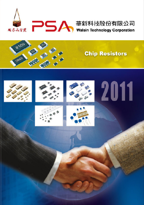
Functional code X : Thick film low ohm M : Metal low ohm N : Metal low ohm, high power W : Thick film low TCR P : Thick film low TCR high power ( 2512 size=2 watt, 2010 size=1 watt, 1210 size=0.5 watt, 1206 size=0.5 watt,
R002
Tolerance F : +/- 1% J : +/- 5% P : Jumper
Packaging code P : 4” reel taping T : 7” reel taping A : 7” reel taping 15Kpcs Q : 10” reel taping G : 13” reel taping R : 0603 2mm pitch taping B : Bulk K : Bulkcase
Termination code L = Sn base (Lead free) 5 3E SSP (total)
WW
25
M
F
T
L
Type code WW: R< 1ohm MW: R< 1ohm Automotive SW: R< 1ohm Anti-sulfuration
Size code 25 : 2512 (6432) 20 : 2010 (5025) 18 : 1218 (3248) 12 : 1206 (3216) 10 : 1210 (3225) 08 : 0805 (2012) 06 : 0603 (1608) 04 : 0402 (1005)
RSC Bio Solutions RSC EnviroLogic HF 68 HP SDS说明书
发布日期: 02-十一月-2016修订日期 14-八月-2017SDS 编号: -企业名称: RSC Bio Solutions 产品名称: RSC EnviroLogic HF 68 HP版本号: 02化学品安全技术说明书按照GB/T 16483、GB/T 17519编制。
1. 化学品及企业标识RSC EnviroLogic HF 68 HP 商品名称ELHP68Part No.RSC Bio Solutions 制造商或供应商600 Radiator RoadIndian Trail, NC 28079地址美国无资料。
联系人电子邮件无资料。
联系电话电话号码:704-684-6100传真:704-257-8996应急电话EMERGENCY PH NO:1-800-661-3558推荐用途及限制用途无资料。
推荐用途02-十一月-2016发布日期14-八月-2017修订日期02-十一月-2016替代日期2. 危险性概述紧急情况概述无资料。
危险类别未被分类。
标签要素无。
象形图警示词无。
危险性说明混合物不符合分类的标准。
防范说明预防措施遵守良好工业卫生习惯。
事故响应操作后洗手。
安全储存远离禁忌物保存。
废弃处置根据当地管理部门的要求对废弃物和残余物进行处理。
产品在正常的使用、储存和运输条件下是稳定的和非活性的。
无异常的火灾或爆炸危险。
物理和化学危险持续的吸入可能是有害的。
预计较低的食入危害。
直接接触可引起眼部暂时刺激。
健康危害产品不被分类为环境有害物质。
然而,这不排除大量的和经常的泄漏物可能对环境产生有害影响或损害。
环境危害补充信息无。
3. 成分/组成信息混合物物质/混合物浓度(%)CAS 号化学名称178603-64-050 - < 60Synthetic Biodegradable Base Oil 40 - < 50低于报告水平的其它成分4. 急救措施移至空气新鲜处。
如果症状持续或恶化,联络医生。
黑体温度计用户手册说明书
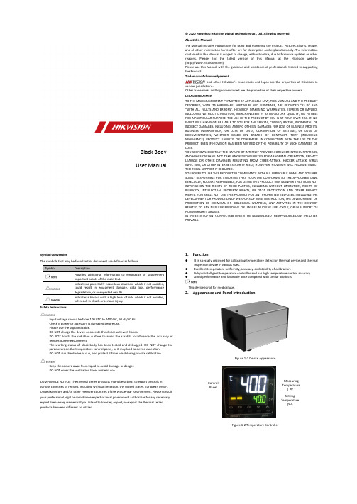
Symbol ConventionThe symbols that may be found in this document are defined as follows. SymbolDescriptionProvides additional information to emphasize or supplement important points of the main text.Indicates a potentially hazardous situation, which if not avoided, could result in equipment damage, data loss, performance degradation, or unexpected results.Indicates a hazard with a high level of risk, which if not avoided, will result in death or serious injury.Safety InstructionsInput voltage should be from 100 VAC to 240 VAC, 50 Hz/60 Hz. Check if power or accessory is damaged before use. Please use the supplied cable.DO NOT charge the device or operate the device with wet hands.DO NOT touch the radiation surface to avoid the scratch to influence the accuracy of temperature measurement.The working status of black body has been tested and debugged. DO NOT change the parameters on the temperature control panel, or it may lead to device exception.DO NOT aim the device at sun, and protect it from wind during on-site calibration.Keep the camera away from liquid to avoid damage or danger.DO NOT cover the ventilation holes while in use.COMPLIANCE NOTICE: The thermal series products might be subject to export controls in various countries or regions, including without limitation, the United States, European Union, United Kingdom and/or other member countries of the Wassenaar Arrangement. Please consult your professional legal or compliance expert or local government authorities for any necessary export license requirements if you intend to transfer, export, re-export the thermal series products between different countries.© 2020 Hangzhou Hikvision Digital Technology Co., Ltd. All rights reserved. About this ManualThe Manual includes instructions for using and managing the Product. Pictures, charts, images and all other information hereinafter are for description and explanation only. The information contained in the Manual is subject to change, without notice, due to firmware updates or other reasons. Please find the latest version of this Manual at the Hikvision website ().Please use this Manual with the guidance and assistance of professionals trained in supporting the Product.Trademarks Acknowledgementand other Hikvision’s trademarks and logos are the properties of Hikvision invarious jurisdictions.Other trademarks and logos mentioned are the properties of their respective owners. LEGAL DISCLAIMERTO THE MAXIMUM EXTENT PERMITTED BY APPLICABLE LAW, THIS MANUAL AND THE PRODUCT DESCRIBED, WITH ITS HARDWARE, SOFTWARE AND FIRMWARE, ARE PROVIDED “AS IS” AND “WITH ALL FAULTS AND ERRORS”. HIKVISION MAKES NO WARRANTIES, EXPRESS OR IMPLIED, INCLUDING WITHOUT LIMITATION, MERCHANTABILITY, SATISFACTORY QUALITY, OR FITNESS FOR A PARTICULAR PURPOSE. THE USE OF THE PRODUCT BY YOU IS AT YOUR OWN RISK. IN NO EVENT WILL HIKVISION BE LIABLE TO YOU FOR ANY SPECIAL, CONSEQUENTIAL, INCIDENTAL, OR INDIRECT DAMAGES, INCLUDING, AMONG OTHERS, DAMAGES FOR LOSS OF BUSINESS PROFITS, BUSINESS INTERRUPTION, OR LOSS OF DATA, CORRUPTION OF SYSTEMS, OR LOSS OF DOCUMENTATION, WHETHER BASED ON BREACH OF CONTRACT, TORT (INCLUDING NEGLIGENCE), PRODUCT LIABILITY, OR OTHERWISE, IN CONNECTION WITH THE USE OF THE PRODUCT, EVEN IF HIKVISION HAS BEEN ADVISED OF THE POSSIBILITY OF SUCH DAMAGES OR LOSS.YOU ACKNOWLEDGE THAT THE NATURE OF INTERNET PROVIDES FOR INHERENT SECURITY RISKS, AND HIKVISION SHALL NOT TAKE ANY RESPONSIBILITIES FOR ABNORMAL OPERATION, PRIVACY LEAKAGE OR OTHER DAMAGES RESULTING FROM CYBER-ATTACK, HACKER ATTACK, VIRUS INFECTION, OR OTHER INTERNET SECURITY RISKS; HOWEVER, HIKVISION WILL PROVIDE TIMELY TECHNICAL SUPPORT IF REQUIRED.YOU AGREE TO USE THIS PRODUCT IN COMPLIANCE WITH ALL APPLICABLE LAWS, AND YOU ARE SOLELY RESPONSIBLE FORENSURING THAT YOUR USECONFORMS TO THE APPLICABLE LAW. ESPECIALLY, YOU ARE RESPONSIBLE, FOR USING THIS PRODUCT IN A MANNER THAT DOES NOT INFRINGE ON THE RIGHTS OF THIRD PARTIES, INCLUDING WITHOUT LIMITATION, RIGHTS OFPUBLICITY, INTELLECTUALPROPERTYRIGHTS,OR DATAPROTECTION AND OTHER PRIVACY RIGHTS. YOU SHALL NOT USE THIS PRODUCT FOR ANY PROHIBITED END-USES, INCLUDING THE DEVELOPMENT OR PRODUCTION OF WEAPONS OF MASS DESTRUCTION, THE DEVELOPMENT OR PRODUCTION OF CHEMICAL OR BIOLOGICAL WEAPONS, ANY ACTIVITIES IN THE CONTEXT RELATED TO ANY NUCLEAR EXPLOSIVE OR UNSAFE NUCLEAR FUEL-CYCLE, OR IN SUPPORT OF HUMAN RIGHTS ABUSES.IN THE EVENT OF ANY CONFLICTS BETWEEN THIS MANUAL AND THE APPLICABLE LAW, THE LATER PREVAILS.1. Function● It is specially designed for calibrating temperature detection thermal device and thermal inspection device in various sizes.● Excellent temperature uniformity, accuracy, and stability of calibration.● Adopts intelligent temperature controller and has high temperature control accuracy. ●Good performance and favorable price compared with similar products.This device is not for medical use.2. Appearance and Panel IntroductionFigure 1-1 Device AppearanceMeasuring Temperature (PV )Setting Temperature(SV)Control PanelFigure 1-2 Temperature ControllerBlack Body User Manual3.4.Mounting1.Check the power supply. The working voltage should be 100 VAC-240 VAC, 35 W.2.Check if the desk is horizontal.3.Mount the device on the desk or a tripod in front of the thermal camera firmly. Makesure that the front of black body can show in the live view of thermal cameracompletely, and outside the temperature measurement area.4.Switch on the device, and the power indicator is on. The factory default settingtemperature is 40 °C.5.Operation1.Connect the black body with a 10 A socket via the power cable.2.Switch on the device, and the power indicator is on. The factory default settingtemperature is 40 °C.3.Wait for 30 minutes after switching on device. You can calibrate the thermal camerawhen the temperature is stable at 40 °C.4.Switch off the black body and store it after use.6.Maintenance1.The black body should be managed and maintained by professional person, andmaintenance and usage should be recorded.2.DO NOT use the device in an environment with oil or chemical air.3.To ensure the temperature accuracy, place the device firmly in the environment withstable temperature. The recommended using environment temperature is 10 °C to25 °C (50 °F to 77 °F)4.Power off the device before mounting or removing it.5.Clean the surface of device with a neutral detergent. Clean the dust on the black bodywith a soft brush.6.Store the device in the packing box after use to prevent dust. Make sure theenvironment temperature is suitable.7.DO NOT dismantle the device without authorization. Contact the professionalspecialist for repairing.8.To ensure the temperature accuracy, it is recommended to calibrate the black bodyonce a year. Please send the device to qualified calibration institute.UD22526B。
Vaisala PWD 系列气象传感器说明书

Key benefitsThe right instrument for the right purposeThe range of visibility instrumentation in the PWD Series ensures the right combination of technology and sensors. This allows you to capture the precise data that satisfies your navigation and planning objectives without overspending on capabilities you don’t need.Easy installation and expandabilityPWD sensors are compact andlightweight (less than 1m long), and are factory-calibrated and plug-and-play ready. They can function stand-alone or as part of an Automated Weather Observing System (AWOS) with flexible mounting on existing masts. Measurement capabilities for all PWD models have easy and economical upgrades to meet your changing measurement needs over time.Accuracy in all conditionsVaisala’s pioneering sensor design enables the PWD Series to provideconstant, reference-grade performance unmatched by other forward scatter technology — even for intenseprecipitation and mixed precipitation.Economical operation and maintenanceThe rugged design uses no movable or consumable parts and is well protected against contaminationwith the optical components pointed downward. Hoods protect the lenses against precipitation, spray, and dust. Its weatherproof design provides accuracy, reduces maintenance, and delivers low life cycle costs.Vaisala Present Weather and Visibility Sensors PWD Series is designed to meet the unique challenges of visibility and present weather measurement for onshore and offshore maritime operations, including harbors,coastal areas, ships, and offshore platforms. Vaisala’s PWD Series is the industry standard, approved by major oil companies.The PWD Series delivers a mix of visibility reporting range (Meteorological Optical Range or MOR), characterization of reduced visibility, precipitation type identification, precipitation accumulation/intensity measurement, and report formats (WMO, NWS code tables). It also includes analog and serial line output and optional hood heaters for winter conditions. The PWD Series provides off-the-shelf accuracy and reliability and can be easily and economically upgraded. Wherever visibility reporting is necessary,Vaisala offers a cost-effective and reliable solution that grows to meet your measurement needs.The visibility at sea depends on many factors, such as humidity, wind speed, temperature, and precipitation. It may sound simple, but any meteorologist will tell youthat visibility is one of the hardest parameters to accurately measure and forecast.Vaisala Present Weather and Visibility Sensors PWD SeriesThe right visibility data for maritime use, at the right priceProduct SpotlightPWD Series at a glanceApplications• Feeding visibility and present weather into shipboard weather systems to optimize route and operational planning.• Informing harbor travel protocols to ensure safe operations in poor visibility.• Monitoring conditions around offshore platforms for effective coordination of supply vessels, helicopters, and other operational support traffic.• Generating detailed forecasts to inform early warning and safety protocols.• Integrating visibility and present weather capture capabilities into an onshore, ship, or offshore platform AWOS. • Calculating visibility information that ships can use to determine safe passage routes into and out of harbors.Key featuresExceptional data capture that measures visibility in maximum ranges from 2 to 50km (1 to 27NM) MOR. Advanced models also capture present weather information.Rugged, weather-proof design that ensures low maintenance need and high data availability.Down-looking sensor hoods protect the optical surfaces from external contaminants.Forward scatter visibility sensors for greater accuracy in calculating visibility.Capacitive RAINCAP® precipitation sensors in advanced models detect multiple precipitation types,intensity, and accumulation.Optional hood heaters prevent the buildup of ice and/or snow in the optical path.Why Vaisala? Experiencewith perspectiveHaving launched our first forward-scatter sensor in1990, Vaisala is a trustedpartner in visibility and precipitation sensors. Our unique understanding of weather measurement has made Vaisala a leader in maritime and aviation weather observation solutions. The technologies we offer are the result of our own R&D,and our solutions and services are used in environmental monitoring systems,helideck monitoring systems, and marine weather reporting worldwide. Our extensive expertise and global presence — with more than 20,000 devices in over 120 countriesand all seven oceans — makesus your global maritimeweather expert.Support to count on Look to Vaisala for dependable support, project capabilities, and training so you can get the most from your system. We provide project management, installation, training, acceptance testing, engineering, consulting,and ongoing service agreements. With decades of experience providing the best technologies and the finest support, Vaisala’s philosophy of partnership is unmatched in the industry. Scan the code formore information Ref. B212256EN-B ©Vaisala 2020This material is subject to copyright protection, with all copyrights retained by Vaisala and its individual partners. All rights reserved. Any logos and/or product names are trademarks of Vaisala or its individual partners. The reproduction, transfer, distribution or storage of information contained in this brochure in any form without the prior written consent of Vaisala is strictly prohibited. All specifications — technical included — are subject to change without notice.。
维萨拉HUMICAP传感器技术说明书

www.vaisala.cn技术说明维萨拉 HUMICAP 传感器以它的高准确度著称,同时能够保证质量和可靠性,具有良好的长期稳定性和很小的湿滞。
工作原理HUMICAP 是一款电容型薄膜聚合物传感器,由上下两个电极板和附着在下极板上的聚合物薄膜组成。
传感器上电极是表面涂覆多孔的金属电极,以保护它免受污染,但可暴露于冷凝环境。
下基板通常是玻璃或陶瓷制成。
当环境空气的相对湿度上升或下降时,薄膜聚合物相应吸收或释放水气。
聚合物薄膜的介电特性取决于吸收的水分量。
传感器周围的相对湿度发生变化时,聚合物薄膜的介电特性也会变化,传感器的电容就会随之变化。
仪表的电子处理部件测量传感器的电容并将其转换为湿度读数。
湿度测量的典型应用维萨拉配备 HUMICAP 传感器的湿度仪表适用于多种应用场合。
从电力和钢铁到生命科学和楼宇自动化,很多行业都需要测量湿度 – 这里只列举了其中几个:在很多干燥过程中必须测量和控制湿度,如建筑材料和造纸,以及流化床干燥器。
工艺过程空气的湿度是指示干燥进度的一个很好的指标。
为确保运行连续且符合规范,洁净室及其他关键环境也需要进行高水准环境测量。
此外,手套箱和隔离器(用于处理水分或气体敏感的材料)也从准确可靠的湿度测量中受益。
在关键环境中测量湿度特别具有挑战性。
在 1973 年,维萨拉推出了薄膜电容型湿度传感器 HUMICAP®。
从那时起,维萨拉成为相对湿度测量产品的生产商和服务提供者,满足客户在相对湿度测量领域的需求。
HUMICAP 简介▪电容型薄膜聚合物传感器▪测量范围为 0...100 %RH▪准确度为 ±0.8 %RH▪可溯源的湿度测量▪1973 年推出HUMICAP 的优点▪良好的长期稳定性▪耐受灰尘和大多数化学物质▪化学物质清除选项可在化学物质浓度很高的环境中进行稳定测量▪传感器加热功能用于在冷凝环境中进行测量▪可从冷凝中恢复用于测量相对湿度的维萨拉 HUMICAP®传感器HUMICAP 传感器的结构。
DA10 实时天气预报数据获取系统说明书
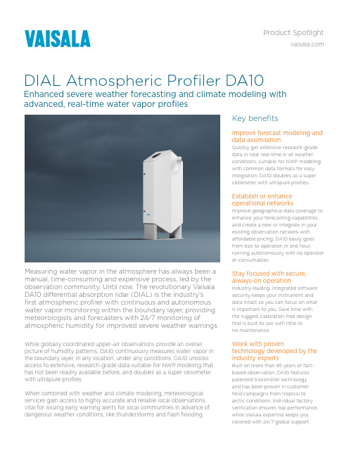
Key benefits Improve forecast modeling and data assimilation Quickly get extensive research-grade data in near real-time in all weather conditions, suitable for NWP modeling with common data formats for easy integration. DA10 doubles as a super ceilometer with ultrapure profiles.Establish or enhance operational networks Improve geographical data coverage to enhance your forecasting capabilities, and create a new or integrate in your existing observation network with affordable pricing. DA10 easily goes from box to operation in one hour, running autonomously with no operator or consumables.Stay focused with secure, always-on operation Industry-leading, integrated software security keeps your instrument and data intact so you can focus on what is important to you. Save time with the rugged, calibration-free design that is built to last with little to no maintenance.Work with proven technology developed by the industry experts Built on more than 85 years of fact-based observation, DA10 features patented transmitter technology and has been proven in customer field campaigns from tropical to arctic conditions. Individual factory verification ensures top performance, while Vaisala expertise keeps youcovered with 24/7 global support.While globally coordinated upper-air observations provide an overallpicture of humidity patterns, DA10 continuously measures water vapor inthe boundary layer, in any location, under any conditions. DA10 unlocksaccess to extensive, research-grade data suitable for NWP modeling thathas not been readily available before, and doubles as a super ceilometerwith ultrapure profiles.When combined with weather and climate modelling, meteorologicalservices gain access to highly accurate and reliable local observations,vital for issuing early warning alerts for local communities in advance ofdangerous weather conditions, like thunderstorms and flash flooding.Measuring water vapor in the atmosphere has always been a manual, time-consuming and expensive process, led by the observation community. Until now. The revolutionary Vaisala DA10 differential absorption lidar (DIAL) is the industry’s first atmospheric profiler with continuous and autonomous water vapor monitoring within the boundary layer, providing meteorologists and forecasters with 24/7 monitoring of atmospheric humidity for improved severe weather warnings.DIAL Atmospheric Profiler DA10Enhanced severe weather forecasting and climate modeling withadvanced, real-time water vapor profilesProduct Spotlight• Water vapor profiling up to 4 km• Uncertainty data is included for easy data assimilation• Attenuated backscatter profiling up to 18 km• NetCDF data format is plug-and-play for modeling, and compatible with third-party visualization tools • Comprehensive system security down to the user level plus remote firmware upgrades fortifies data management and data sources• Single lens technology minimizes multiple scattering for improved detection in harsh conditions, while excellent overlap ensures low altitude detection (below 200 m)• Optimized near and far range optics provide excellent full-range measurement profiles• Superior signal-to-noise ratio ensures high level of detail in profiles• Clouds and sky condition reporting - DA10 works as super ceilometer and includes ceilometer functions Trusted weather observations for a sustainable future/meteorologyDIAL in smarter, faster, continuous humidity profilingWhy Vaisala?Expertise and innovationYour communities rely on you to provide the most reliable and accurate weather information to ensure a better and safer daily life. We are here to help you realize that.As the day-to-day impacts from climate change and extreme weather events continue to grow, Vaisala is innovating and equipping meteorology professionals to better understand, forecast, and explain the phenomena. Backed by 85 years of proven weather measurement expertise, meteorologists in more than 170 countries trust Vaisala solutions to help them make informed decisions.Performance and support you can count onYou’re covered if questions arise with 24/7 global support—now and in the future—plus project capabilities and training so you can get the most from your system. With decades of experience providing the best technologies and the finest support, Vaisala’s philosophy of partnership is unmatched in the industry.Scan the code formore information Ref. B212719EN-B ©Vaisala 2023This material is subject to copyright protection, with all copyrightsretained by Vaisala and its individual partners. All rights reserved.Any logos and/or product names are trademarks of Vaisala or itsindividual partners. The reproduction, transfer, distribution orstorage of information contained in this brochure in any formwithout the prior written consent of Vaisala is strictly prohibited.All specifications — technical included — are subject to change without notice.。
射频同轴连接器系列
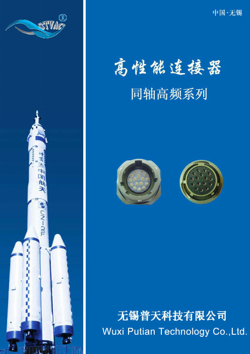
BNC-50KY-5
BNC-50KY-6
型号 Type
LC
Miltary Number
M39012/
UG
BNC-50KY-1 27.0 3.3
UG1094-U
BNC-50KY-2A 30.15 6.6 21-0002 UG1094A-U
咨询电话: 0510-85219650 传真:0510-85215738 e-mail: gtvac@
BNC 型:外导体内径为 6.5mm(0.256in)、卡口锁定、特性阻抗为 50Ω 该连接器适用于低功率,它利用卡口连接结构以获得快速连接和分离,并能与国外同类产品 相互换,广泛地用于无线电设备和电子仪器中连接射频同轴电缆。 Type BNC:with inner diameter of outer conductor 6.5 mm(0.256 in) With bayonet lock-Characteristic impedance 50Ω These connectors are for low power,quick connect/disconnect applications using a bayonet type coiping mechanism and can be interchangeable with the same-type connectors of abroad。
3.0
SYV-50-2-1
4.2
SYV-50-2-2
50Ω
5.3
SYV-50-3
A01
5.3
SYV-75-3
6.4 SDY-4 SYV-75-4
弯式插头 Angle plugs
BNC-JW3 3.0 BNC-JW4 4.2 BNC-JW5 5.3 BNC-JW12 5.3
Enphase M215微型逆变器说明书
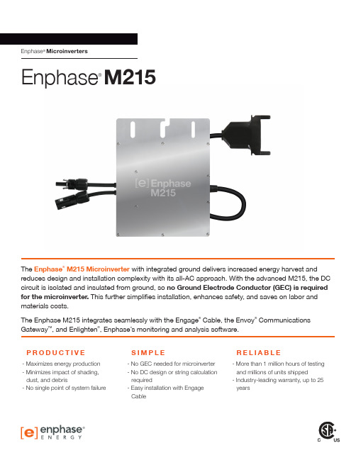
* Frequency ranges can be extended beyond nominal if required by the utility
To learn more about Enphase Microinverter technology,
®
visit
© 2014 Enphase Energy. All rights reserved. All trademarks or brands in this document are registered by their respective owner.
57-62.5 Hz
57-62.5 Hz
Power factor
>0.95
>0.95
Maximum units per 20 A branch circuit
25 (three phase)
17 (single phase)
Maximum output fault current
850 mA rms for 6 cycles
PRODUCTIVE
- Maximizes energy production - Minimizes impact of shading,
dust, and debris - No single point of system failure
SIMPLE
- No GEC needed for microinverter - No DC design or string calculation
Communication
Power line
Integrated ground
The DC circuit meets the requirements for ungrounded PV arrays in NEC 690.35. Equipment ground is provided in the Engage Cable. No additional GEC or ground is required. Ground fault protection (GFP) is integrated into the microinverter.
巨风空压机的英文标识

巨风空压机的英文标识The English Identification of Giant Wind Air CompressorWhen it comes to the industrial field, air compressors play a vital role in various applications. One popular brand in this industry is Giant Wind, a well-known manufacturer of air compressors. As with any product, having a clear and accurate English identification for the Giant Wind air compressors is crucial for international recognition and understanding. In this article, we will explore the English identification of the Giant Wind air compressors and its importance.The English identification for the Giant Wind air compressors is "Giant Wind Air Compressor." This identification accurately represents the brand name and the specific product, providing clarity and understanding for both domestic and international customers. It is essential to have a distinct and recognizable English identification to facilitate communication and marketing efforts worldwide.Having a clear English identification for the Giant Wind air compressors is particularly important for international trade and business. English is the lingua franca of global commerce, and having a well-translated and easily identifiable product name can make a significant difference in attracting international customers and expanding the brand's reach.Moreover, the English identification should accurately convey the product's characteristics and features. In the case of Giant Wind air compressors, the English identification successfully communicates the primary purpose of the product –compressing air. This identification is concise, straightforward, and easy to remember, which aids in the brand's visibility and recognition.In addition to the English identification, it is also essential to consider the logo and other visual elements associated with the Giant Wind air compressors. The logo should be designed in a way that complements the English identification and represents thebrand's identity and values. A well-designed logo can enhance brand recognition and create a strong visual association with the product.When designing the English identification and logo for the Giant Wind air compressors, it is crucial to consider cultural and linguistic differences. The identification and logo should be culturally sensitive and avoid any potential misinterpretations or offensive connotations in different regions or languages. Conducting thorough research and consulting with professionals in the field of linguistics and design can help ensure that the English identification and logo are suitable for international audiences.Furthermore, the English identification of the Giant Wind air compressors should be consistent across all marketing materials and platforms. Consistency in branding helps build trust and recognition among customers. It also strengthens the brand's image and distinguishes it from competitors.In conclusion, the English identification for the Giant Wind air compressors is "Giant Wind Air Compressor." This identification accurately represents the brand and the product, facilitating international recognition and understanding. Having a clear and distinctive English identification is crucial for effective communication, marketing, and international trade. It should accurately convey the product's characteristics, be culturally sensitive, and consistent across all platforms. With a well-designed English identification and logo, Giant Wind can establish a strong presence in the global air compressor market.。
zemax rsce用法
zemax rsce用法Zemax是光学设计软件中的一款优秀产品,其RSCE功能更是备受广大光学工程师的喜爱。
在光学设计中,RSCE功能被广泛应用于复杂光学系统的设计和优化。
本文将介绍Zemax中的RSCE功能的使用方法。
一、认识RSCE功能RSCE是Zemax软件中的一个重要模块,主要用于光学系统的设计和优化。
该模块提供了多种算法,如光线追迹算法、数值优化算法等,可以快速准确地计算出光学系统的性能指标,如光束质量、数值孔径、焦距等。
通过RSCE模块,用户可以轻松地对光学系统进行优化,以达到最佳性能。
二、使用RSCE功能的基本步骤1.导入设计数据:首先,用户需要将需要设计的光学系统数据导入到Zemax 软件中。
这些数据包括光学元件的尺寸、形状、材料等。
2.创建模型:在导入数据后,用户需要使用RSCE模块创建光学系统的模型。
这一步需要设置光线追迹参数、数值优化参数等。
3.优化设计:在创建模型后,用户可以根据需求对光学系统进行优化设计。
可以选择不同的算法和优化目标,如最小化光束质量、最大化通光孔径等。
4.分析结果:优化设计完成后,用户可以使用RSCE模块分析结果,包括优化后的光学系统的性能指标、优化过程的数据等。
5.输出设计结果:最后,用户可以将优化后的设计结果导出,用于后续的光学加工和测试。
三、RSCE功能的优点和应用场景RSCE功能在光学设计中具有以下优点:1.快速准确:RSCE模块采用了先进的数值优化算法,可以快速准确地计算出光学系统的性能指标,大大提高了设计效率。
2.优化能力强:RSCE模块提供了多种优化算法,可以根据不同的需求选择合适的算法对光学系统进行优化,以达到最佳性能。
3.适用范围广:RSCE模块适用于各种复杂的光学系统设计,如透镜、反射镜、棱镜等。
RSCE功能的应用场景包括但不限于:复杂光学系统的设计、高精度光学元件的设计、光束质量要求较高的系统设计等。
四、总结本文介绍了Zemax软件中的RSCE功能的使用方法,包括认识RSCE功能、使用RSCE功能的基本步骤、RSCE功能的优点和应用场景。
rsc认证标准
rsc认证标准
RSC认证标准可能涉及到多个方面,以下是一些可能的标准:
1. 安全性:RSC认证首先需要确保所认证的产品或服务是安全的,不会对用户或环境造成危害。
2. 可靠性:RSC认证需要确保所认证的产品或服务具有足够的可靠性,能够满足用户的需求和期望。
3. 性能:RSC认证需要确保所认证的产品或服务具有足够的性能表现,包括但不限于效率、精度、稳定性等。
4. 质量:RSC认证需要确保所认证的产品或服务符合预定的质量要求,包括材料、工艺、检测等方面的要求。
5. 环境:RSC认证需要确保所认证的产品或服务符合环境保护的要求,包括能效、排放、回收等方面的要求。
具体标准可能会因产品或服务的不同而有所差异,建议查阅相关的RSC认证标准和规范,或者咨询专业的认证机构或专家以获取更详细的信息。
维萨拉 WindCube Scan 扫描激光雷达 - 空气质量监测和预报说明书
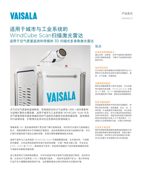
优点优良的态势感知能力通过对风、边界层、云和气溶胶后向散射同步进行准确的测量,了解大气边界层和风的基本状况。
良好的灵活性全方位的三维扫描模式其测量范围可达10公里和可为多种活动定制丰富的扫描模式:监测、大气剖面、风廓线等。
见解和报告概览具有多种数据管理工具任您选择,可为您提供丰富的活动见解。
WindCube Scan 可通过 API 请求、与 FTP 服务器的通信或用户友好的图形用户界面,提供灵活的数据管理。
轻松可靠的操作该设备具有坚固的外壳和加热扫描镜头,即使在恶劣的环境(包括潮湿、灰尘、冰、大雨和雪)中也能提供可靠的性能。
可以安装在城市和工业区,也可以移动和改变用途以支持不同的项目。
性能良好的组件可提供持续及时的测量以及免人工干预式维护。
4G 连接可让您使用更多功能,无需以太网电缆。
行业多方面支持维萨拉保修和维修服务保障设备具备持久性能并提供准确可靠的测量结果。
有我们数十年的经验、科学的方法和支持服务为后盾,您可以在整个生命周期内充分利用设备。
准确掌握 ABL 波动规律有助于更全面了解污染物浓度。
风评估可以显示污染物通过风力、局部再循环和水平传输的扩散情况。
这些因素通常会加快污染物的扩散:对它们进行测量有助于做出正确的决策,并显示哪些缓解措施较为有效。
适用于城市与工业系统的 WindCube Scan 可借助数据处理,全天候对风、气溶胶后向散射、云和边界层高度同步进行良好的测量。
它是一种多功能工具,可在长达 6 km 、8 km 或 10 km (具体取决于型号)的多种扫描模式下实时获取准确的风和气溶胶后向散射测量结果。
该工具采用大气结构检测算法,可对对流层中的云层和气溶胶层进行检测、定位和分类,以及对大气边界层 (ABL) 高度进行监测。
该技术也适用于矿山、港口和其他行业产生大量颗粒物排放的行业,这些颗粒物会以难以预测的方式随风扩散。
天气对空气质量有直接影响,而局部风况和大气边界层 (ABL) 动向是影响污染物扩散的主要因素。
上海绿态电子科技有限公司石墨烯超级电容器产品手册-GTCAP

上海绿态电子科技有限公司品质管理系统:工业标准ISO9001-20152020产品手册地址:上海市浦东新区张江高科碧波路5号,邮编201203电话:400-061-5118************手机:+86-158********Skype:greentech58QQ:361796650邮箱:*********************网址:Https://GT CAP®高端电容器供应商石墨烯超级电容器GTCAP设计和生产的石墨烯超级电容器和储能模组,具有能量密度大、功率大、寿命长、温度范围宽、自放电小等特点。
石墨烯超级电容器GTCAP®GTCAP 石墨烯超级电容器和其他储能产品对比:项目GTCAP 石墨烯超级电容器铅酸蓄电池锂电池工作温度范围-40℃~+70℃0℃~+45℃-25℃~+60℃循环寿命>50,000次300~500次1000~2000次能量密度75Wh/kg 40Wh/kg 150Wh/kg 功率密度500W/kg 150~400W/kg 315W/kg 维护免维护通常费用高通常费用高充电时长≤10分钟8~12小时6~8小时爆炸风险无无有燃烧风险无无有电极材料活性炭铅酸锂氧化物与碳材料电解液材料有机溶剂硫酸溶液有机溶剂蛛网图优势单体石墨烯超级电容器GT CAP®石墨烯超级电容器单体单体产品型号GTEG-2R7-153UN3566GTEG-2R7-903UT60138GTEG-2R7-104UT66161GTEG-2R7-154UT66161GTEG-2R7-164UT66161容量15000F/4.5Ah90000F/25Ah100000F/30Ah150000F/40Ah160000F/45Ah 最佳工作电压 2.7V~1.5V 2.7V~1.5V 2.7V~1.5V 2.7V~1.5V 2.7V~1.5V 储能10Wh58Wh69Wh92Wh103Wh 工作温度-40℃~+65℃-40℃~+65℃-40℃~+65℃-40℃~+65℃-40℃~+65℃最大充电电流10A150A180A240A270A循环寿命(100%DOD)30000次50000次50000次50000次50000次尺寸35*66mm60*138mm66*161mm66*161mm66*161mm净重120g800g1200g1250g1255gGT CAP®提供瞬时能量在-20℃放电能量≥70%x初始能量在-40℃放电能量≥53%x初始能量在-20℃充电能量≥92%x初始能量在-40℃充电能量≥68%x初始能量50000次循环寿命或>30年低ESR增强太阳能效率高免维护高可靠性50000次循环寿命或>30年性能良好免维护温度范围宽高可靠性安全GTCAP石墨烯超级电容器广泛应用于UPS、引擎冷启动、太阳能路灯、太阳能系统、电信基站、军用设备、汽车、AGV和叉车等。
- 1、下载文档前请自行甄别文档内容的完整性,平台不提供额外的编辑、内容补充、找答案等附加服务。
- 2、"仅部分预览"的文档,不可在线预览部分如存在完整性等问题,可反馈申请退款(可完整预览的文档不适用该条件!)。
- 3、如文档侵犯您的权益,请联系客服反馈,我们会尽快为您处理(人工客服工作时间:9:00-18:30)。
RSC Adv.:具有高光学透明度、良好机械强度和有效PM2.5捕获能力的图案化纳米纤维空气过滤器
DOI: 10.1039/d0ra01967d PM2.5由于其粒径小、活性强、易于附着有毒物质以及在大气中停留时间长等原因,对人体健康和日常生产具有重大影响。
在这项工作中,研究者提出了具有高光学透明度、强大的机械强度和有效的PM2.5捕获能力的图案化纳米纤维空气过滤器。
在此,为了通过简便的静电纺丝法制备透明的空气过滤器,研究者选择了三种具有微结构的图案化金属网格作为负极接收器基材,并将聚合物纤维直接电纺到支撑网格上。
与随机取向的纳米纤维(在本文中称为“RO NFs”)和市售面罩相比,图案化空气过滤器显示出良好的机械性能,其表面的水接触角约为122-143°(RO NFs的水接触角为81°)。
此外,图案化的纳米纤维显示出高孔隙率(> 80%),其平均孔径约为0.5838–0.8686 mm(RO NFs的平均孔径为0.4374 mm)。
结果表明,在模拟雾霾污染条件下,当透光率高达69%时,透明的图案化空气过滤器具有99.99%的最佳PM2.5过滤效率。
图1.(i)具有不同图案的各种纳米纤维膜的显微照片、(ii)SEM图像、(iii)纤维直径分布:(a)RO NFs、(b)PW NFs、(c)HB NFs和(d)LS NFs。
图2.纳米纤维膜的应力-应变响应。
图3.(a)纳米纤维膜的孔径分布分析。
(b)各种纳米纤维膜的平均孔径和最小孔径及其相应的孔隙率。
(c)RO NFs和各种图案化纳米纤维膜表面的水接触角随时间(0到3000 ms)的变化。
(d)由CCD相机在0 ms、1000 ms、2000 ms和3000 ms记录的显示接触角随时间变化的光学显微镜图像。
图4.(a)将制备的透明空气滤网集成到蜻蜓模型的机翼中,以观察其在布料向日葵前面的透射率。
(b)带有电动风扇的透明图案化空气滤网在风速为2.5 m s-1下的摄影图像。
(c)各种纤维膜在可见光波长范围内的透光率,厚度为4 mm。
(d)不同膜厚和(e)不同网格目数的HB NFs的透光率(测量波长范围:300-800 nm)。
插图是相应的数字图像。
图5.(a)空气过滤实验装置。
(b)在模拟的雾霾环境中,在图案化纳米纤维膜上进行PM2.5过滤过程的光学图像。
(c)比较各种图案化纤维膜、随机取向的纤维膜和市售面罩之间的去除效率和(d)质量因子。
(e)从约600至35 μg cm-3(温度为18℃,湿度为45%;空气流速为2.2 m s-1)除去PM2.5的时间。
(f)比较目前的HB图案化空气过滤器和其他报告的空气过滤器的去除效率:明胶/PT/明胶空气过滤器,HAP/CT空气过滤器,PAN透明空气过滤器和带电的TAF空气过滤器。
文章链接:/News/Detail/43440
来源:易丝帮。
