功率管STP80NF12
晶体管参数
2SB817 PNP 100 -12 -140
2SD1047 NPN 100 12 140
2SA1106 PNP 100 -10 -140
2SC2581 NPN 100 10 200
2SA1215 PNP 150 -4 -160
2SC2921 NPN 150 15 160
2SA1047 PNP -15 150 -160 -200
2SA1943 PNP -15 150 -230 -250
2SA1294 PNP -15 130 -230 -250
2SA1003 PNP -12 120 -150 -200
2SA1065 PNP -10 120 -150 -200
(A) (W) (V) (V)
3DF50C NPN 50 500 200 250
3DD5686 NPN 50 300 200 250
2SC1435 NPN 40 300 600 800-1200
2SC2445 NPN 30 250 300/200 400/300
DFP4N60 可替代型号:FQPF5N60C(SSS4N60B),2SK2750(2SK3567),IRFIBC40GLC,STP4NK60ZFP
DFF4N60 可替代型号:FQPF5N60C(SSS4N60B),2SK2750(2SK3567),IRFIBC40GLC,STP4NK60ZFP
TO-247AC 600V Warp 60-150kHz Discrete IGBT;100℃ 20A/600V
IRG4PF50W
TO-247AC 900V Warp 20-100kHz Discrete IGBT;100℃ 28A/900V
电子镇流器常用三极管的管脚和参数
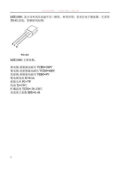
MJE13001是小功率高压高速开关三极管,典型应用:荧光灯电子镇流器。
它采用TO-92封装,管脚排列如图:MJE13001主要参数:集电极-基极最高耐压VCBO=500V集电极-发射极最高耐压VCEO=400V发射极-基极最高耐压VEBO=9V集电极电流IC=0.3A耗散功率PC=7W结温Tj=150℃贮藏温度TSTG=-50~150℃直流放大系数HFE=8~403DD13001是硅NPN型小功率开关三极管,主要用于节能灯电子镇流器、手机充电器等开关电源电路。
3DD13001具有击穿电压高、反向漏电流小、开关速度快、饱和压降低、高温性能好等特点。
采用TO-251封装的3DD13001管脚排列如图:1脚:基极;2脚:集电极;3脚:发射极3DD13001主要参数:集电极最大耗散功率PCM=1.2W (Tamb=25℃)集电极最大允许电流ICM=0.2A集电极-基极反向击穿电压BVCBO=600V集电极-发射极反向击穿电压BVCEO=400V发射极-基极反向击穿电压BVEBO=7V结温Tj=150℃贮藏温度TSTG=-55~150℃直流放大系数=8~40MJE13002是高压高速开关三极管,国产同类型号为3DD13002。
它主要用于电子节能灯、日光灯电子镇流器,以及其它开关电路中。
MJE13002(3DD13002)采用TO-126封装的外形尺寸和管脚排列如图:MJE13002(3DD13002)主要参数VCBO=600VVCEO=400VVEBO=7VIC=1APC=1.2WTj=150℃TSTG=-55~150℃ICBO=100μAIEBO=100μAHFE=10~40VCE(sat) =0.5VVBE(sat) =1.0VfT=4MHzTf=0.6μsMJE13003是主要用于节能灯及荧光灯电子镇流器的高反压大功率开关三极管,硅NPN型,采用TO-126封装,它的外形和管脚排列如下:MJE13003主要参数集电极-基极电压VCBO 700 V集电极-发射极电压VCEO 400 V发射极-基极电压VEBO 9V集电极电流IC 2.0 A集电极耗散功率PC 40 W最高工作温度Tj 150 °C贮存温度Tstg -65-150 °C集电极-基极截止电流ICBO (VCB=700V) 100 μA集电极-发射极截止电流ICEO (VCE=400V,IB=0) 250 μA集电极-发射极电压VCEO (IC=10mA,IB=0) 400 V发射极-基极电压VEBO (IE=1mA,IC=0) 9 V直流电流放大倍数5~403DD13005是高反压大功率开关三极管,硅材料NPN型,平面扩散工艺制造,开关速度快,耐压高。
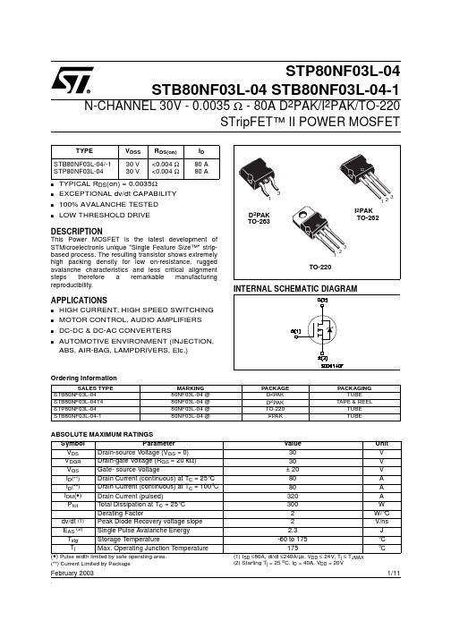
STP80NF03L-04_03中文资料
1/11February 2003.STP80NF03L-04STB80NF03L-04 STB80NF03L-04-1N-CHANNEL 30V - 0.0035 Ω - 80A D 2PAK/I 2PAK/TO-220STripFET™ II POWER MOSFETs TYPICAL R DS (on) = 0.0035Ωs EXCEPTIONAL dv/dt CAPABILITY s 100% AVALANCHE TESTED sLOW THRESHOLD DRIVEDESCRIPTIONThis Power MOSFET is the latest development of STMicroelectronis unique "Single Feature Size™" strip-based process. The resulting transistor shows extremely high packing density for low on-resistance, rugged avalanche characteristics and less critical alignment steps therefore a remarkable manufacturing reproducibility.APPLICATIONSs HIGH CURRENT, HIGH SPEED SWITCHING s MOTOR CONTROL, AUDIO AMPLIFIERS s DC-DC & DC-AC CONVERTERSs AUTOMOTIVE ENVIRONMENT (INJECTION, ABS, AIR-BAG, LAMPDRIVERS, Etc.)TYPEV DSS R DS(on)I D STB80NF03L-04/-1STP80NF03L-0430 V 30 V<0.004 Ω<0.004 Ω80 A 80 AOrdering InformationABSOLUTE MAXIMUM RATINGS(Pulse width limited by safe operating area.(**) Current Limited by Package(1) I SD ≤80A, di/dt ≤240A/µs, V DD ≤ 24V, T j ≤ T JMAX (2) Starting T j = 25 o C, I D = 40A, V DD = 20VSALES TYPEMARKING PACKAGE PACKAGINGSTB80NF03L-0480NF03L-04 @D 2PAK TUBE STB80NF03L-04T480NF03L-04 @D 2PAK TAPE & REELSTP80NF03L-0480NF03L-04 @TO-220TUBE STB80NF03L-04-180NF03L-04 @I 2PAKTUBESymbol Parameter Value Unit V DS Drain-source Voltage (V GS = 0)30V V DGRDrain-gate Voltage (R GS = 20 k Ω)30V V GS Gate- source Voltage± 20V I D (**)Drain Current (continuous) at T C = 25°C 80A I D (**)Drain Current (continuous) at T C = 100°C 80A I DM (•)Drain Current (pulsed)320A P tot Total Dissipation at T C = 25°C300W Derating Factor2W/°C dv/dt (1)Peak Diode Recovery voltage slope 2V/ns E AS (2)Single Pulse Avalanche Energy 2.3J T stg Storage Temperature -60 to 175°C T j Max. Operating Junction Temperature 175°CSTB80NF03L-04/-1/STP80NF03L-042/11THERMAL DATAELECTRICAL CHARACTERISTICS (T case = 25 °C unless otherwise specified)OFFON (*)DYNAMICRthj-case Rthj-ambT lThermal Resistance Junction-case Thermal Resistance Junction-ambientMaximum Lead Temperature For Soldering PurposeMax Max Typ0.562.5300°C/W °C/W °CSymbol ParameterTest ConditionsMin.Typ.Max.Unit V (BR)DSS Drain-sourceBreakdown Voltage I D = 250 µAV GS = 030V I DSSZero Gate VoltageDrain Current (V GS = 0)V DS = Max RatingV DS = Max Rating T C = 125°C 110µA µA I GSSGate-body Leakage Current (V DS = 0)V GS = ± 20 V±100nASymbol ParameterTest ConditionsMin.Typ.Max.Unit V GS(th)Gate Threshold Voltage V DS = V GS I D = 250 µA 1V R DS(on)Static Drain-source On ResistanceV GS = 10 V I D = 40 A V GS = 4.5 VI D = 40 A0.00350.0040.0040.0055ΩΩSymbol ParameterTest ConditionsMin.Typ.Max.Unit g fs (*)Forward Transconductance V DS = 15 VI D =15 A50S C iss C oss C rssInput Capacitance Output Capacitance Reverse Transfer CapacitanceV DS = 25V, f = 1 MHz, V GS = 055001670290pF pF pFSTB80NF03L-04/-1/STP80NF03L-04SWITCHING ONSWITCHING OFFSOURCE DRAIN DIODE(*)Pulsed: Pulse duration = 300 µs, duty cycle 1.5 %.(•)Pulse width limited by safe operating area.Symbol ParameterTest ConditionsMin.Typ.Max.Unit t d(on)t r Turn-on Delay Time Rise TimeV DD = 15 VI D = 40 A R G =4.7 Ω V GS = 4.5 V (Resistive Load, Figure 3)30270ns ns Q g Q gs Q gdTotal Gate Charge Gate-Source Charge Gate-Drain ChargeV DD =24V I D =80 A V GS =4.5V852340110nC nC nCSymbol ParameterTest ConditionsMin.Typ.Max.Unit t d(off)t f Turn-off Delay Time Fall TimeV DD = 15 VI D = 40 A R G =4.7Ω, V GS = 4.5 V (Resistive Load, Figure 3)11095ns ns t r(Voff)t f t cOff-Voltage Rise Time Fall TimeCross-over TimeV clamp = 24 VI D = 80 A R G =4.7Ω V GS = 4.5 V (Inductive Load, Figure 5)12575125ns ns nsSymbol ParameterTest ConditionsMin.Typ.Max.Unit I SD I SDM (•)Source-drain CurrentSource-drain Current (pulsed)80320A A V SD (*)Forward On Voltage I SD = 80 AV GS = 01.5V t rr Q rr I RRMReverse Recovery Time Reverse Recovery Charge Reverse Recovery CurrentI SD = 80 Adi/dt = 100A/µs V DD = 20 V T j = 150°C (see test circuit, Figure 5)750.154ns µC AELECTRICAL CHARACTERISTICS (continued)STB80NF03L-04/-1/STP80NF03L-04STB80NF03L-04/-1/STP80NF03L-04STB80NF03L-04/-1/STP80NF03L-046/11Fig. 3: Switching Times Test Circuits For ResistiveFig. 5: Test Circuit For Inductive Load Switching7/11STB80NF03L-04/-1/STP80NF03L-04DIM.mm.inch.MIN.TYP. MAX.MIN.TYP. TYP .A 4.4 4.60.1730.181A1 2.49 2.690.0980.106A20.030.230.0010.009B 0.70.930.0280.037B2 1.14 1.70.0450.067C 0.450.60.0180.024C2 1.21 1.360.0480.054D 8.959.350.3520.368D180.315E 1010.40.3940.409E18.50.334G 4.88 5.280.1920.208L 1515.850.5910.624L2 1.27 1.40.0500.055L3 1.4 1.750.0550.069M 2.43.20.0940.126R 0.40.015V20°8°0°8°D 2PAK MECHANICAL DATASTB80NF03L-04/-1/STP80NF03L-0410/11DIM.mm inchMIN.MAX.MIN.MAX.A010.510.70.4130.421B015.715.90.6180.626D 1.5 1.60.0590.063D1 1.59 1.610.0620.063E 1.65 1.850.0650.073F11.411.60.4490.456K0 4.8 5.00.1890.197P0 3.9 4.10.1530.161P111.912.10.4680.476P2 1.9 2.100750.082R50 1.574T0.250.35.0.00980.0137W23.724.30.9330.956DIM.mm inchMIN.MAX.MIN.MAX.A33012.992B 1.50.059C12.813.20.5040.520D20.20.795G24.426.40.960 1.039N100 3.937T30.4 1.197BASE QTY BULK QTY10001000REEL MECHANICAL DATA* on sales typeTUBE SHIPMENT (no suffix)* TAPE AND REEL SHIPMENT (suffix ”T4”)*D2PAK FOOTPRINTTAPE MECHANICAL DATA元器件交易网STB80NF03L-04/-1/STP80NF03L-04 Information furnished is believed to be accurate and reliable. However, STMicroelectronics assumes no responsibility for the consequencesof use of such information nor for any infringement of patents or other rights of third parties which may result from its use. No license is grantedby implication or otherwise under any patent or patent rights of STMicroelectronics. Specifications mentioned in this publication are subjectto change without notice. This publication supersedes and replaces all information previously supplied. STMicroelectronics products are notauthorized for use as critical components in life support devices or systems without express written approval of STMicroelectronics.The ST logo is registered trademark of STMicroelectronics® 2002 STMicroelectronics - All Rights ReservedAll other names are the property of their respective owners.STMicroelectronics GROUP OF COMPANIESAustralia - Brazil - Canada - China - Finland - France - Germany - Hong Kong - India - Israel - Italy - Japan - Malaysia - Malta - Morocco -Singapore - Spain - Sweden - Switzerland - United Kingdom - United States.11/11。
士兰微电子SD7530 LED照明高功率因数反激式PWM控制器说明书

高功率因数反激式PWM控制器
日光灯
产品规格分类
产品名称 封装形式 打印名称 材料 包装
无铅料管SD7530 DIP-8-300-2.54
SD7530
无铅料管
SD7530S
SD7530S SOP-8-225-1.27
无铅编带SD7530STR SOP-8-225-1.27
SD7530S
内部框图
40
OL -600/800
误差
放大器
比较器
SD7530说明书
电气参数 (除非特别指定,V
CC
=22V;C O=1nF;-25°C<T amb<125°C)
TEL 158********
SD7530说明书
TEL 158********
管脚描述
封装外形图
SD7530说明书
MOS电路操作注意事项:
静电在很多地方都会产生,采取下面的预防措施,可以有效防止MOS电路由于受静电放电影响而引起的损坏:
• 操作人员要通过防静电腕带接地。
• 设备外壳必须接地。
• 装配过程中使用的工具必须接地。
• 必须采用导体包装或抗静电材料包装或运输。
声明:
•士兰保留说明书的更改权,恕不另行通知!客户在下单前应获取最新版本资料,并验证相关信息是否完整和最新。
•任何半导体产品特定条件下都有一定的失效或发生故障的可能,买方有责任在使用Silan产品进行系统设计和整机制造时遵守安全标准并采取安全措施,以避免潜在失败风险可能造成人身伤害或财产损
失情况的发生!
•产品提升永无止境,我公司将竭诚为客户提供更优秀的产品!
TEL 158********。
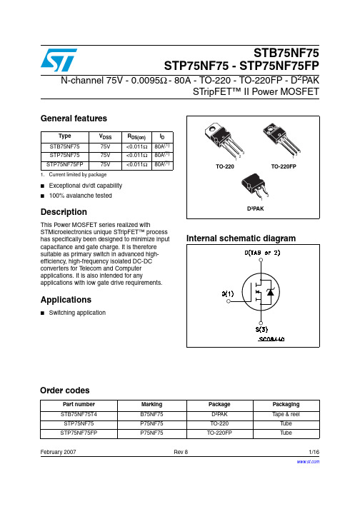
75NF75MOS管
February 2007Rev 81/16Order codesPart number Marking Package Packaging STB75NF75T4B75NF75D²P AK Tape & reel STP75NF75P75NF75TO-220T ube STP75NF75FPP75NF75TO-220FPT ubeSTB75NF75STP75NF75 - STP75NF75FPN-channel 75V - 0.0095Ω - 80A - TO-220 - TO-220FP - D 2P AKSTripFET™ II Power MOSFETGeneral features■Exceptional dv/dt capability ■100% avalanche testedDescriptionThis Power MOSFET series realized withSTMicroelectronics unique STripFET™ process has specifically been designed to minimize input capacitance and gate charge. It is therefore suitable as primary switch in advanced high-efficiency, high-frequency isolated DC-DC converters for T elecom and Computer applications. It is also intended for anyapplications with low gate drive requirements.Applications■Switching applicationType V DSS R DS(on)I D STB75NF7575V <0.011Ω80A (1)STP75NF7575V <0.011Ω80A (1)STP75NF75FP75V<0.011Ω80A (1)1.Current limited by package Contents STB75NF75 - STP75NF75 - STP75NF75FPContents1Electrical ratings . . . . . . . . . . . . . . . . . . . . . . . . . . . . . . . . . . . . . . . . . . . . 32Electrical characteristics . . . . . . . . . . . . . . . . . . . . . . . . . . . . . . . . . . . . . 42.1Electrical characteristics (curves) . . . . . . . . . . . . . . . . . . . . . . . . . . . . 6 3Test circuit . . . . . . . . . . . . . . . . . . . . . . . . . . . . . . . . . . . . . . . . . . . . . . . . 9 4Package mechanical data . . . . . . . . . . . . . . . . . . . . . . . . . . . . . . . . . . . . 10 5Packaging mechanical data . . . . . . . . . . . . . . . . . . . . . . . . . . . . . . . . . . 14 6Revision history . . . . . . . . . . . . . . . . . . . . . . . . . . . . . . . . . . . . . . . . . . . 152/16STB75NF75 - STP75NF75 - STP75NF75FP Electrical ratings3/161 Electrical ratingsTable 1.Absolute maximum ratingsSymbol ParameterValueUnitD 2PAK /TO-220TO-220FPV DS Drain-source voltage (V GS = 0)75V V DGR Drain-gate voltage (R GS = 20K Ω)75V V GS Gate-source voltage± 20V I D (1)1.Current limited by packageDrain current (continuous) at T C = 25°C 8080 A I D (1)Drain current (continuous) at T C =100°C 7070 A I DM (2)2.Pulse width limited by safe operating areaDrain current (pulsed)320320 A P TOTT otal dissipation at T C = 25°C 30045W Derating factor2.00.3W/°C dv/dt (3)3.I SD ≤ 80A, di/dt ≤ 300A/µs, V DD ≤ V (BR)DSS , T j ≤ T JMAX Peak diode recovery voltage slope 12V/ns E AS (4)4. Starting T J = 25 o C, I D = 40A, V DD = 37.5VSingle pulse avalanche energy700mJ V ISO Insulation withstand voltage (RMS) from allthree leads to external heat sink (t=1s;T C =25°C)--2000V T J T stgOperating junction temperature Storage temperature-55 to 175°CTable 2.Thermal dataSymbol ParameterValueUnitD 2PAK /TO-220TO-220FP R thJC Thermal resistance junction-case max 0.53.33°C/W R thJA Thermal resistance junction-ambient max 62.5°C/W T lMaximum lead temperature for solderingpurpose (1)1. 1.6mm from case for 10sec)300°CElectrical characteristics STB75NF75 - STP75NF75 - STP75NF75FP4/162 Electrical characteristics(T CASE =25°C unless otherwise specified)Table 3.On/off statesSymbol ParameterTest conditions Min.Typ.Max.Unit V (BR)DSS Drain-source breakdownvoltageI D = 250µA, V GS = 075V I DSS Zero gate voltage drain current (V GS = 0)V DS = Max rating,V DS = Max rating @125°C 110µA µA I GSS Gate body leakage current (V DS = 0)V GS = ±20V±100nA V GS(th)Gate threshold voltage V DS = V GS , I D = 250µA 234V R DS(on)Static drain-source on resistanceV GS = 10V , I D = 40A0.00950.011ΩTable 4.DynamicSymbol ParameterTest conditions Min.Typ.Max.Unit g fs (1)1.Pulsed: pulse duration=300µs, duty cycle 1.5%Forward transconductance V DS = 15V , I D = 40A 20S C iss C oss C rss Input capacitance Output capacitance Reverse transfer capacitance V DS =25V , f = 1 MHz, V GS = 03700730240pF pF pF Q g Q gs Q gdTotal gate charge Gate-source charge Gate-drain chargeV DD = 60V , I D = 80A V GS =10V1172747160nC nC nCSTB75NF75 - STP75NF75 - STP75NF75FP Electrical characteristics5/16Table 5.Switching timesSymbol ParameterTest conditions Min.Typ.Max.Unit t d(on)t r t d(off)t fTurn-on delay time Rise timeTurn-off delay time Fall timeV DD = 37.5V , I D = 45A, R G =4.7Ω, V GS =10V Figure 15 on page 9251006630ns ns ns nsTable 6.Source drain diodeSymbol ParameterTest conditionsMinTyp.Max Unit I SD Source-drain current 80A I SDM (1)1.Pulse width limited by safe operating area Source-drain current (pulsed)320A V SD (2)2.Pulsed: pulse duration=300µs, duty cycle 1.5%Forward on voltage I SD = 80A, V GS = 0 1.5V t rr Q rr I RRMReverse recovery time Reverse recovery charge Reverse recovery currentI SD = 80A,di/dt = 100A/µs,V DD = 25V , T J = 150°C Figure 17 on page 913266010ns nC AElectrical characteristics STB75NF75 - STP75NF75 - STP75NF75FP6/162.1 Electrical characteristics (curves)Figure 1.Safe operating area for TO-220 -Figure 2.Thermal impedancefor TO-220 -Figure 3.Safe operating area for TO-220FP Figure 4.Thermal impedance for TO-220FPFigure 5.Output characterisics Figure 6.Transfer characteristicsSTB75NF75 - STP75NF75 - STP75NF75FP Electrical characteristics7/16Figure 7.Transconductance Figure 8.Static drain-source on resistanceFigure 9.Gate charge vs gate-source voltage Figure 10.Capacitance variationsFigure 11.Normalized gate threshold voltageFigure 12.Normalized on resistance vsElectrical characteristicsSTB75NF75 - STP75NF75 - STP75NF75FP8/16Figure 13.Source-drain diode forwardFigure 14.Normalized B VDSS vs temperatureSTB75NF75 - STP75NF75 - STP75NF75FP Test circuit9/163 Test circuitFigure 15.Switching times test circuit forFigure 16.Gate charge test circuitFigure 17.Test circuit for inductive loadFigure 18.Unclamped inductive load testFigure 19.Unclamped inductive waveformPackage mechanical data STB75NF75 - STP75NF75 - STP75NF75FP 4 Package mechanical dataIn order to meet environmental requirements, ST offers these devices in ECOPACK®packages. These packages have a Lead-free second level interconnect . The category ofsecond level interconnect is marked on the package and on the inner box label, incompliance with JEDEC Standard JESD97. The maximum ratings related to solderingconditions are also marked on the inner box label. ECOPACK is an ST trademark.ECOPACK specifications are available at: 10/16STB75NF75 - STP75NF75 - STP75NF75FP Package mechanical data11/16Package mechanical data STB75NF75 - STP75NF75 - STP75NF75FP12/16STB75NF75 - STP75NF75 - STP75NF75FP Package mechanical data13/16Packaging mechanical data STB75NF75 - STP75NF75 - STP75NF75FP14/165 Packaging mechanical dataTAPE AND REEL SHIPMENT D2PAK FOOTPRINT* on sales type DIM.mm inchMIN.MAX.MIN.MAX. A33012.992 B 1.50.059C12.813.20.5040.520 D20.20795G24.426.40.960 1.039 N100 3.937T30.4 1.197 BASE QTY BULK QTY10001000REEL MECHANICAL DATADIM.mm inch MIN.MAX.MIN.MAX.A010.510.70.4130.421 B015.715.90.6180.626 D 1.5 1.60.0590.063 D1 1.59 1.610.0620.063 E 1.65 1.850.0650.073 F11.411.60.4490.456 K0 4.8 5.00.1890.197 P0 3.9 4.10.1530.161 P111.912.10.4680.476 P2 1.9 2.10.0750.082 R50 1.574T0.250.350.00980.0137 W23.724.30.9330.956 TAPE MECHANICAL DATASTB75NF75 - STP75NF75 - STP75NF75FP Revision history15/166 Revision historyTable 7.Revision historyDate RevisionChanges03-Aug-20066Complete version 15-Sep-20067R DS(on) value update27-Feb-20078The document has been reformattedSTB75NF75 - STP75NF75 - STP75NF75FP16/16Please Read Carefully:Information in this document is provided solely in connection with ST products. STMicroelectronics NV and its subsidiaries (“ST”) reserve the right to make changes, corrections, modifications or improvements, to this document, and the products and services described herein at any time, without notice.All ST products are sold pursuant to ST’s terms and conditions of sale.Purchasers are solely responsible for the choice, selection and use of the ST products and services described herein, and ST assumes no liability whatsoever relating to the choice, selection or use of the ST products and services described herein.No license, express or implied, by estoppel or otherwise, to any intellectual property rights is granted under this document. If any part of this document refers to any third party products or services it shall not be deemed a license grant by ST for the use of such third party products or services, or any intellectual property contained therein or considered as a warranty covering the use in any manner whatsoever of such third party products or services or any intellectual property contained therein.UNL ESS OTHERWISE SET FORTH IN ST’S TERMS AND CONDITIONS OF SAL E ST DISCL AIMS ANY EXPRESS OR IMPL IED WARRANTY WITH RESPECT TO THE USE AND/OR SAL E OF ST PRODUCTS INCL UDING WITHOUT L IMITATION IMPL IED WARRANTIES OF MERCHANTABILITY, FITNESS FOR A PARTICULAR PURPOSE (AND THEIR EQUIVALENTS UNDER THE LAWS OF ANY JURISDICTION), OR INFRINGEMENT OF ANY PATENT, COPYRIGHT OR OTHER INTELLECTUAL PROPERTY RIGHT. UNL ESS EXPRESSL Y APPROVED IN WRITING BY AN AUTHORIZED ST REPRESENTATIVE, ST PRODUCTS ARE NOT RECOMMENDED, AUTHORIZED OR WARRANTED FOR USE IN MILITARY, AIR CRAFT, SPACE, LIFE SAVING, OR LIFE SUSTAINING APPLICATIONS, NOR IN PRODUCTS OR SYSTEMS WHERE FAILURE OR MALFUNCTION MAY RESULT IN PERSONAL INJURY, DEATH, OR SEVERE PROPERTY OR ENVIRONMENTAL DAMAGE. ST PRODUCTS WHICH ARE NOT SPECIFIED AS "AUTOMOTIVE GRADE" MAY ONLY BE USED IN AUTOMOTIVE APPLICATIONS AT USER’S OWN RISK.Resale of ST products with provisions different from the statements and/or technical features set forth in this document shall immediately void any warranty granted by ST for the ST product or service described herein and shall not create or extend in any manner whatsoever, any liability of ST.ST and the ST logo are trademarks or registered trademarks of ST in various countries.Information in this document supersedes and replaces all information previously supplied.The ST logo is a registered trademark of STMicroelectronics. All other names are the property of their respective owners.© 2007 STMicroelectronics - All rights reservedSTMicroelectronics group of companiesAustralia - Belgium - Brazil - Canada - China - Czech Republic - Finland - France - Germany - Hong Kong - India - Israel - Italy - Japan - Malaysia - Malta - Morocco - Singapore - Spain - Sweden - Switzerland - United Kingdom - United States of America。
max4080工作原理

max4080工作原理Max4080是一款常见的音频功率放大器芯片,它具有许多优秀的特性和工作原理。
本文将详细介绍Max4080的工作原理及其在音频应用中的作用。
一、Max4080的概述Max4080是一款高性能音频功率放大器,采用了先进的BTL(桥式输出)结构和多种保护功能。
它能够提供高达20W的输出功率,并具有低失真、低噪声和高效率等优点。
Max4080广泛应用于家庭音响、汽车音响和专业音频设备等领域。
二、Max4080的工作原理Max4080的工作原理主要包括输入信号处理、功率放大和保护功能三个方面。
1. 输入信号处理Max4080接收来自音频源的输入信号,经过输入级进行放大和滤波处理。
输入级主要包括差动放大器和输入滤波器。
差动放大器能够抑制共模干扰,并提高信号的动态范围。
输入滤波器则用于滤除高频噪声和杂散信号,以保证输入信号的纯净性。
2. 功率放大经过输入信号处理的信号进入功率放大器阶段。
Max4080采用了BTL结构,即桥式输出,能够提供更大的输出功率。
BTL结构由两个输出级组成,每个输出级都由一个功率管和一个反相器组成。
其中一个输出级负责输出正半周信号,另一个输出级负责输出负半周信号。
通过两个输出级的合作,Max4080能够提供较高的功率输出,并保证输出信号的正负半周对称。
3. 保护功能Max4080还具有多种保护功能,以保证其工作的可靠性和安全性。
其中包括过热保护、短路保护和过载保护等。
过热保护功能能够在芯片温度过高时自动降低功率输出或关断输出,以防止芯片受损。
短路保护功能能够在输出短路时及时切断输出,以保护功率管和音箱不受损害。
过载保护功能能够在输出功率超过额定值时自动降低输出,以保护芯片和音箱不受过载的影响。
三、Max4080在音频应用中的作用Max4080作为一款高性能音频功率放大器,在音频应用中发挥着重要的作用。
1. 提供高质量的音频输出Max4080具有低失真和低噪声的特点,能够保证音频信号的高质量输出。
常用MOS管型号大全

高频低噪放大
20V0.5-8mA0.25W100MHz3dB
2SK214
NMOS
GSD
高频高速开关
160V0.5A30W
2SK241
NMOS
DSG
高频放大
-20V0.03A0.2W100MHz1.7dB
2SK304
NJ
GSD
音频功放
30V0.6-12mA0.15W
2SK385
NMOS
GDS
高速开关
J177
PMOS
2SJ177
PMOS
GDS
激励(无)
-60V20A35W140/580nS0.085
J201
PMOS
GDS
高频放大
10V0.4A1.3W8GHZ
2SJ312
PMOS
GDS
激励
60V14A40W30/120nS0.12
2SK30
NJ
SDG
低放音频
-50V0.5mA0.1W0.5dB
2SK30A
NMOS
GDS
高速开关
500V15A100W0.4
2SK623
NMOS
GDS
高速开关
250V20A120W0.15
2SK727
NMOS
GDS
电源开关
-900V5A125W110/420nS2.5
2SK734
NMOS
GDS
电源开关
450V15A150W160/250nS0.52
2SK785
NMOS
GDS
2SK2487
NMOS
GDS
监视器用电源
900V8A140W 50/153nS1.1
部份电磁炉功率管参数及带换

部份电磁炉功率管参数及带换部份电磁炉功率管参数及带换!1.....SGW25N120----西门子公司出品,耐压1200V,电流容量25℃时46A,100℃时25A,内部不带阻尼二极管,所以应用时须配套6A/1200V以上的快速恢复二极管(D11)使用,该IGBT配套6A/1200V以上的快速恢复二极管(D11)后可代用SKW25N120。
2,, SKW25N120----西门子公司出品,耐压1200V,电流容量25℃时46A,100℃时25A,内部带阻尼二极管,该IGBT可代用SGW25N120,代用时将原配套SGW25N120的D11快速恢复二极管拆除不装。
3,, GT40Q321----东芝公司出品,耐压1200V,电流容量25℃时42A,100℃时23A, 内部带阻尼二极管, 该IGBT可代用SGW25N120、SKW25N120, 代用SGW25N120时请将原配套该IGBT的D11快速恢复二极管拆除不装。
4.. GT40T101----东芝公司出品,耐压1500V,电流容量25℃时80A,100℃时40A,内部不带阻尼二极管,所以应用时须配套15A/1500V以上的快速恢复二极管(D11)使用,该IGBT配套6A/1200V以上的快速恢复二极管(D11)后可代用SGW25N120、SKW25N120、GT40Q321, 配套15A/1500V以上的快速恢复二极管(D11)后可代用GT40T301。
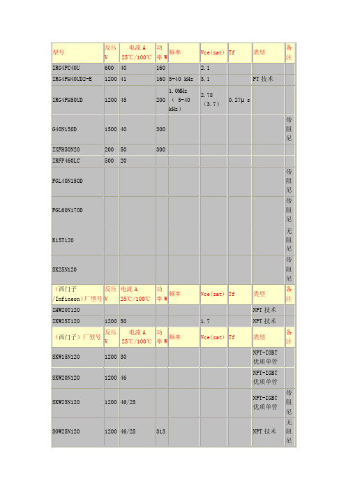
5,, GT40T301----东芝公司出品,耐压1500V,电流容量25℃时80A,100℃时40A, 内部带阻尼二极管, 该IGBT可代用SGW25N120、SKW25N120、GT40Q321、GT40T101, 代用SGW25N120和GT40T101时请将原配套该IGBT的D11快速恢复二极管出!6,, GT40Q321, FGL40N150D, FGL60N170D, FGA25N120,SK25N120, G40 N150D,FGA25N135,1MBH25D--120,GP20B120UD--E, IXGH20N120BDI,以上功率管内部都带阻尼管|家电维修|技术咨询|资料下载g K c @O0Z7,,SGW25N120,K15T120以上的管子内部不带阻尼,如果要代换一上功率管时可以在电路板上安装2个以上的阻尼二极管耐压1200V以上,电流在8A以上,接时正极接S极,负极接D极即可<如S5J53、BY4591500等>|家电维修|技术咨询|资料下载"O p/W4x i$];x7Y2[ P T6E1^ ^-Q"v V A型号反压电流功率频率Vce Tf 阻尼类型IRG4PC40U 600V 40 160 2.1IRG4PH40UD2-E 1200 41 160 5-40kHz 3.1 PT技术IRG4PH50UD 1200 45 200 1.0MHz 2.78 0.27μsGT8Q101 1200 8 100GT15Q101 1200 15 150IXFH50N20 200 50 300IRFP460LC 500 20G40N150D 1500 40 300SGW25N120 1200 25 313 无NPT技术IHW20T120 NPT技术IKW25T120 1200 50 1.7 NPT技术SKW15N120 1200 30 NPT-IGBT优质单管SKW25N120 1200 46 有NPT-IGBT优质单管CT60AM-18F 900 60 单管有DCT90AM-18 900 60 单管有DGT8J101 600 8 单管GT8Q101 1200 8 单管GT20J301 600 20 单管GT25Q101 1200 25 单管GT30J301 600 30 单管GT15Q101 1200 15 单管GT50J301 600 50 单管GT15Q102 1200 15 单管无DGT80J101 600 80 单管GT25Q102 1200 25 单管无DGT60M301 900 60 单管GT25Q301 1200 25 单管GT60M303 900 60 单管GT40Q322 1200 39 200 1.0MHz 3.0 0.18μs单管PT技术GT60N321 1000 60 单管GT40T301 1500 40 有单管GT40T101 1500 80 无GT40Q321 1200 42 2.8 0.41μs有单管PT技术GT40Q323 1200 39 3.0 0.14μs单管GT40Q301 1500 40 3.7 0.23μs单管GT50J301 600 50 2.1 0.15μs单管GT30J322* 600 30 2.1 0.25μs单管GT50J122 600 60 1.9 0.16μs单管GT60J323 600 60 1.9 0.16μs单管GT50J322 600 50 2.1 0.15μs单管1MBH50-060 600 50 3101MBH50D-100 1000 50 310 有D1MBH25-120 1200 25 3101MBH60-100 1000 60 260 无D1MBH25D-120 1200 25 310 有D1MBH60D-100 1000 60 260 有D1XDP20N60B(D1) 600 20 TO-2201XGH45N120 1200 45 TO-2471XDH35N60B(D1) 600 35 TO-2471XGH15N120B 1200 15 高速TO-2471XDH20N120(D1) 1200 25 TO-2471XGH35N120B 1200 35 高速TO-2471XDH30N120(D1) 1200 38 TO-2471XGH16N170A 1700 16 高速TO-2471XDN55N120(D1) 1200 62 SOT-227B1XGH24N170A 1700 24 高速TO-2471XDH60N60B2(D1) 600 60 高速TO-2471XGH32N170A 1700 32 高速TO-247HGTG5N120BND 1200 21 167HGTG18N120BND 1200 50 390HGTG10N120BND 1200 35 298FGA15N120AND 1200 24 192HGTG11N120CND 1200 43 295FGA25N120AND 1200 40 310 NPT技术FGA25N120ANTD 1200 25 310 2.0 NPT技术APT50GF60BR 600 50 0-50KHZ NPT结构易并联无DAPT100GF60JR 600 100 0-50KHZ NPT结构易并联无DAPT20GF120BR 1200 20 0-50KHZ NPT结构易并联无DAPT33GF120BR 1200 33 0-50KHZ NPT结构易并联无DAPT50GF120LR 1200 50 0-50KHZ NPT结构易并联无DAPT15GT60BR 600 15 0-50KHZ NPT结构易并联无DAPT30GT60BR 600 30 0-50KHZ NPT结构易并联无DAPT60GT60JR 600 60 0-50KHZ NPT结构易并联无DAPT50GF60LRD 600 50 0-50KHZ NPT结构易并联有DAPT100GF60JRD 600 100 0-50KHZ NPT结构易并联有DAPT20GF120BRD 1200 20 0-50KHZ NPT结构易并联有DAPT33GF120LRD 1200 33 0-50KHZ NPT结构易并联有DAPT50GF120JRD 1200 50 0-50KHZ NPT结构易并联有DAPT15GT60BRD 600 15 0-50KHZ NPT结构易并联有DAPT30GT60BRD 600 30 0-50KHZ NPT结构易并联有DAPT60GT60JRD 600 60 0-50KHZ NPT结构易并联有DAPT15GP60B 600 27 0-200KHZ PT结构不易并联无DAPT30GP60B 600 49 0-200KHZ PT结构不易并联无DAPT50GP60B 600 72 0-200KHZ PT结构不易并联无DAPT15GP90B 900 21 0-200KHZ PT结构不易并联无DAPT25GP90B 900 36 0-200KHZ PT结构不易并联无DAPT40GP90B 900 50 0-200KHZ PT结构不易并联无DAPT13GP120B 1200 20 0-200KHZ PT结构不易并联无DAPT25GP120B 1200 33 0-200KHZ PT结构不易并联无DAPT35GP120B 1200 46 0-200KHZ PT结构不易并联无DAPT45GP120B 1200 54 0-200KHZ PT结构不易并联无DAPT35GP120J 1200 29 0-200KHZ PT结构不易并联无DAPT45GP120J 1200 34 0-200KHZ PT结构不易并联无DAPT75GP120J 1200 57 0-200KHZ PT结构不易并联无DAPT15GP60BDF1 600 27 0-200KHZ PT结构不易并联有DAPT30GP60BDF1 600 49 0-200KHZ PT结构不易并联有DAPT50GP60B2DF2 600 72 0-200KHZ PT结构不易并联有DAPT15GP90BDF1 900 21 0-200KHZ PT结构不易并联有DAPT25GP90BDF1 900 36 0-200KHZ PT结构不易并联有DAPT40GP90B2DF2 900 50 0-200KHZ PT结构不易并联有DAPT13GP120BDF1 1200 20 0-200KHZ PT结构不易并联有DAPT25GP120BDF1 1200 33 0-200KHZ PT结构不易并联有DAPT35GP120B2DF2 1200 46 0-200KHZ PT结。
STP80NF70

STP80NF70N-channel 68 V, 0.0082 Ω, 98 A, TO-220STripFET™ II Power MOSFET3 June 2009 Rev 11/12Contents STP80NF70Contents1Electrical ratings . . . . . . . . . . . . . . . . . . . . . . . . . . . . . . . . . . . . . . . . . . . . 32Electrical characteristics . . . . . . . . . . . . . . . . . . . . . . . . . . . . . . . . . . . . . 42.1Electrical characteristics (curves) . . . . . . . . . . . . . . . . . . . . . . . . . . . . . 6 3Test circuits . . . . . . . . . . . . . . . . . . . . . . . . . . . . . . . . . . . . . . . . . . . . . . . 8 4Package mechanical data . . . . . . . . . . . . . . . . . . . . . . . . . . . . . . . . . . . . . 9 5Revision history . . . . . . . . . . . . . . . . . . . . . . . . . . . . . . . . . . . . . . . . . . . 112/12STP80NF70Electrical ratings3/121 Electrical ratingsTable 2.Absolute maximum ratingsSymbol ParameterValue Unit V DS Drain-source voltage (V GS = 0)68V V GS Gate-source voltage± 20V I D Drain current (continuous) at T C = 25 °C 98A I D Drain current (continuous) at T C =100 °C 68A I DM (1)1.Pulse width limited by safe operating areaDrain current (pulsed)392A P TOTT otal dissipation at T C = 25 °C 190W Derating factor1.27W/°C dv/dt (2)2.I SD ≤ 80 A, di/dt ≤ 300 A/µs, V DD ≤ V (BR)DSS , T J ≤ T JMAX Peak diode recovery voltage slope 13V/ns E AS (3)3. Starting T J = 25 o C, I D = 40 A, V DD = 34 VSingle pulse avalanche energy 700mJ T stg Storage temperature-55 to 175°C T JOperating junction temperature175°CTable 3.Thermal dataSymbol ParameterValue Unit R thj-case Thermal resistance junction-case max 0.79°C/W R thj-ambThermal resistance junction-ambient max 62.5°C/W T lMaximum lead temperature for solderingpurpose (1)1. 1.6mm from case for 10 sec300°CElectrical characteristics STP80NF704/122 Electrical characteristics(T CASE =25°C unless otherwise specified)Table 4.On/off statesSymbol ParameterTest conditions Min.Typ.Max.Unit V (BR)DSS Drain-source breakdownvoltageI D = 250 µA, V GS = 068V I DSS Zero gate voltage drain current (V GS = 0)V DS = Max rating,V DS = Max rating @125 °C 110µA µA I GSS Gate body leakage current (V DS = 0)V GS = ±20 V±100nA V GS(th)Gate threshold voltage V DS = V GS , I D = 250 µA 234V R DS(on)Static drain-source on resistanceV GS = 10 V , I D = 40 A0.00820.0098ΩTable 5.DynamicSymbol ParameterTest conditions Min.Typ.Max.Unit g fs (1)1.Pulsed: pulse duration=300µs, duty cycle 1.5%Forward transconductance V DS = 15 V , I D = 40 A 60S C iss C oss C rss Input capacitance Output capacitance Reverse transfer capacitance V DS =25 V , f = 1 MHz, V GS = 02550550175pF pF pF Q g Q gs Q gdTotal gate charge Gate-source charge Gate-drain chargeV DD = 34 V , I D = 80 A V GS =10 V751730nC nC nCSTP80NF70Electrical characteristics5/12Table 6.Switching timesSymbol ParameterTest conditions Min.Typ.Max.Unit t d(on)t r t d(off)t fTurn-on delay time Rise timeTurn-off delay time Fall timeV DD = 34 V , I D = 40 A, R G =4.7 Ω, V GS =10 V Figure 13 on page 817609075ns ns ns nsTable 7.Source drain diodeSymbol ParameterTest conditionsMinTyp.Max Unit I SD Source-drain current 80A I SDM (1)1.Pulse width limited by safe operating area Source-drain current (pulsed)320A V SD (2)2.Pulsed: pulse duration=300µs, duty cycle 1.5%Forward on voltage I SD = 80 A, V GS = 0 1.5V t rr Q rr I RRMReverse recovery time Reverse recovery charge Reverse recovery currentI SD = 80 A,di/dt = 100 A/µs,V DD = 25 V , T J = 150 °C Figure 15 on page 8701604.7ns µC AElectrical characteristics STP80NF706/122.1 Electrical characteristics (curves)Figure 2.Safe operating areaFigure 3.Thermal impedanceSTP80NF70Electrical characteristics Figure 8.Gate charge vs gate-source voltage Figure 9.Capacitance variations7/12Test circuits STP80NF708/123 Test circuitsFigure 13.Switching times test circuit forFigure 14.Gate charge test circuitSTP80NF70Package mechanical data 4 Package mechanical dataIn order to meet environmental requirements, ST offers these devices in different grades ofECOPACK® packages, depending on their level of environmental compliance. ECOPACK®specifications, grade definitions and product status are available at: .ECOPACK is an ST trademark.9/12Package mechanical data STP80NF7010/12STP80NF70Revision history 11/125 Revision historyTable 8.Document revision history DateRevision Changes03-Jun-20091First releaseSTP80NF7012/12Please Read Carefully:Information in this document is provided solely in connection with ST products. STMicroelectronics NV and its subsidiaries (“ST”) reserve the right to make changes, corrections, modifications or improvements, to this document, and the products and services described herein at any time, without notice.All ST products are sold pursuant to ST’s terms and conditions of sale.Purchasers are solely responsible for the choice, selection and use of the ST products and services described herein, and ST assumes no liability whatsoever relating to the choice, selection or use of the ST products and services described herein.No license, express or implied, by estoppel or otherwise, to any intellectual property rights is granted under this document. If any part of this document refers to any third party products or services it shall not be deemed a license grant by ST for the use of such third party products or services, or any intellectual property contained therein or considered as a warranty covering the use in any manner whatsoever of such third party products or services or any intellectual property contained therein.UNL ESS OTHERWISE SET FORTH IN ST’S TERMS AND CONDITIONS OF SAL E ST DISCL AIMS ANY EXPRESS OR IMPL IED WARRANTY WITH RESPECT TO THE USE AND/OR SAL E OF ST PRODUCTS INCL UDING WITHOUT L IMITATION IMPL IED WARRANTIES OF MERCHANTABILITY, FITNESS FOR A PARTICULAR PURPOSE (AND THEIR EQUIVALENTS UNDER THE LAWS OF ANY JURISDICTION), OR INFRINGEMENT OF ANY PATENT, COPYRIGHT OR OTHER INTELLECTUAL PROPERTY RIGHT. UNL ESS EXPRESSL Y APPROVED IN WRITING BY AN AUTHORIZED ST REPRESENTATIVE, ST PRODUCTS ARE NOT RECOMMENDED, AUTHORIZED OR WARRANTED FOR USE IN MILITARY, AIR CRAFT, SPACE, LIFE SAVING, OR LIFE SUSTAINING APPLICATIONS, NOR IN PRODUCTS OR SYSTEMS WHERE FAILURE OR MALFUNCTION MAY RESULT IN PERSONAL INJURY, DEATH, OR SEVERE PROPERTY OR ENVIRONMENTAL DAMAGE. ST PRODUCTS WHICH ARE NOT SPECIFIED AS "AUTOMOTIVE GRADE" MAY ONLY BE USED IN AUTOMOTIVE APPLICATIONS AT USER’S OWN RISK.Resale of ST products with provisions different from the statements and/or technical features set forth in this document shall immediately void any warranty granted by ST for the ST product or service described herein and shall not create or extend in any manner whatsoever, any liability of ST.ST and the ST logo are trademarks or registered trademarks of ST in various countries.Information in this document supersedes and replaces all information previously supplied.The ST logo is a registered trademark of STMicroelectronics. All other names are the property of their respective owners.© 2009 STMicroelectronics - All rights reservedSTMicroelectronics group of companiesAustralia - Belgium - Brazil - Canada - China - Czech Republic - Finland - France - Germany - Hong Kong - India - Israel - Italy - Japan - Malaysia - Malta - Morocco - Singapore - Spain - Sweden - Switzerland - United Kingdom - United States of America。
常用二极管
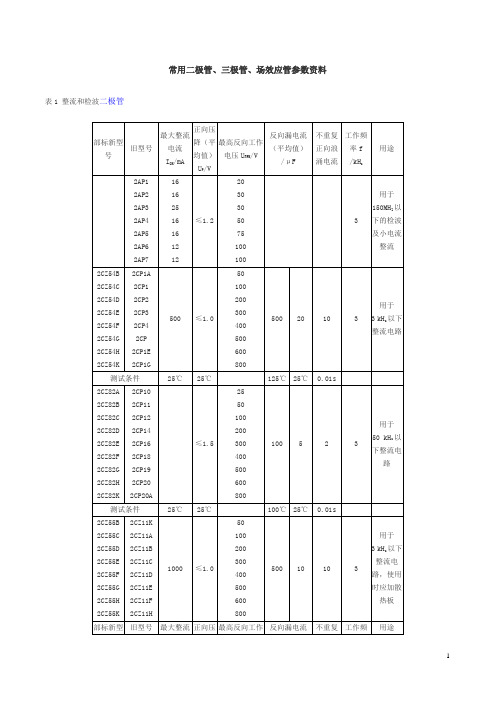
≥30
≥300
3DG130D
≥60
≥45
≤0.5
≤1
≥30
≥300
测试条件
Ic=
100μA
Ic=
100μA
UCB=10V
UCE=10V
UCE=10V
Ic=50mA
UCE=10V
IE=3mA
fT=100MHZ
表103AG高频小功率锗管及其他同类型锗管
参数
型号
PCM/mW
ICM/mA
U(BR)CEO/V
1
60
3
2CW130
2CW22
3~4.5
600
3000
≤0.5
≤-8
≤250
3
≤20
100
2CW131
2CW22A
4.5~5.8
500
-6~4
≤300
3
≤15
100
2CW132
2CW22B
5.5~6.5
460
-3~5
≤250
3
≤12
100
2CW133
2CW22C
6.2~7.5
400
≤6
≤200
3
≤6
≤15
2DW7C
6.0~6.5
≤5
测试条件
工作电流=10 mA
反向电压=1V
工作电流=10 mA
表4发光二极管
型号
发光
颜色
最大工作电流/mA
正向压降/V
一般工作电流/mA
发光波长/A
发光亮度
/光通量
发光功率/ mW
HG5200砷化镓二极管
红外
3(A)
电磁炉三极管型号代换
APT50GP60B
600 72
APT15GP90B
900 21
APT25GP90B
900 36
APT40GP90B
900 50
APT13GP120B
1200 20
0-50KHZ 0-50KHZ 0-50KHZ 0-50KHZ 0-50KHZ 0-50KHZ 0-200KHZ 0-200KHZ 0-200KHZ 0-200KHZ 0-200KHZ 0-200KHZ 0-200KHZ
易并联 有 D
NPT 结构 易并联 有 D
NPT 结构 易并联 有 D
NPT 结构 易并联 有 D
NPT 结构 易并联 有 D
NPT 结 构 易并 联 有D
NPT 结 构 易并 联 有D
PT 结 构 不易 并联 无 D
PT 结 构 不易 并联 无 D
PT 结 构 不易 并联 无 D
PT 结 构 不易 并联 无 D
0-200KHZ 0-200KHZ 0-200KHZ 0-200KHZ 0-200KHZ 0-200KHZ 0-200KHZ 0-200KHZ 0-200KHZ 0-200KHZ 0-200KHZ 0-200KHZ 0-200KHZ 0-200KHZ
PT 结 构 不易 并联 无 D
PT 结 构 不易 并联 无 D
3.0
0.14μ s 单管
单管
无 阻 尼
带
单管
阻
尼
2.1
0.15μ s 单管
2.1
0.25μ s 单管
GT50J122 GT60J323 GT50J322
(富士)厂型号
1MBH50-060 1MBH50D-100 1MBH25-120 1MBH60-100 1MBH25D-120 1MBH60D-100 1MBH60-170
基于UC3844的电流控制型反激变换器分析与设计

基于UC3844的电流控制型反激变换器分析与设计云珂【摘要】分析反激变换器工作的基本原理,给出电路参数的选取原则以及RCD吸收电路的设计方法,基于电流型控制芯片UC3844,设计了满载功率36 W的反激变换器进行实验验证.实验结果表明,设计的电路满足设计要求,具有精度高、纹波小、效率高等优点.【期刊名称】《通信电源技术》【年(卷),期】2018(035)006【总页数】5页(P144-148)【关键词】反激变换器;RCD;UC3844;电流型控制【作者】云珂【作者单位】南京理工大学自动化学院,江苏南京 210094【正文语种】中文0 引言反激变换器具有体积小、成本低、可靠性高以及易于实现多路输出等特点,在中小功率领域得到了广泛应用,特别适用于作为各类控制系统的辅助电源[1]。
反激变换器中电感电流变化率较大,非常适合电流控制型的应用。
在反激变换器中,首先推荐使用电流控制型。
但是,由于变压器漏感的存在,反激变换器在开关管关断瞬间会产生很大的尖峰电压,使得开关管承受较高的电压应力,甚至可能导致开关管损坏[2-3]。
因此,为确保反激变换器安全可靠工作,必须引入钳位电路吸收漏感能量。
钳位电路可分为有源[4-5]和无源[6-7]钳位电路两类,其中无源钳位电路因不需控制和驱动电路而被广泛应用。
本文分析了反激变换器的工作原理,详细说明了电路参数的设计方法,并基于UC3844控制芯片,设计了满载功率为36 W的反激变换器,以验证设计参数[8] 。
1 反激变换器的工作原理反激变换器(Flyback Converter)本质上属于Buck-Boost变换器,输入回路与输出回路隔离,既可以升压也可以降压,广泛应用于100 W以内的隔离式开关电源。
反激变换器的初级回路主要由输入滤波电容Cin1、PWM控制器、启动电路及控制器供电电路、反激变压器主绕组、开关管Q以及尖峰脉冲吸收电路等部分组成;而次级回路主要由反激变压器次级绕组、整流二极管D3、输出滤波电容C0等部分组成。
NTMFS2D5N08X MOSFET 产品说明说明书
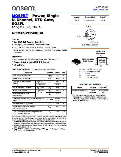
DATA SHEET MOSFET – Power, SingleN-Channel, STD Gate,SO8FL80 V, 2.1 m W, 181 ANTMFS2D5N08XFeatures∙Low QRR, Soft Recovery Body Diode∙Low R DS(on) to Minimize Conduction Losses∙Low QG and Capacitance to Minimize Driver Losses∙These Devices are Pb−Free, Halogen Free/BFR Free and are RoHSCompliantApplications∙Synchronous Rectification (SR) in DC−DC and AC−DC∙Primary Switch in Isolated DC−DC Converter∙Motor DrivesMAXIMUM RATINGS (T J = 25︒C unless otherwise stated)Parameter Symbol Value UnitDrain−to−Source Voltage V DSS80VGate−to−Source Voltage V GS±20VContinuous Drain Current (Note 1)T C = 25︒C I D181A T C = 100︒C128Power Dissipation (Note 1)T C = 25︒C P D148W Pulsed Drain Current T C = 25︒C, t p = 100 m s I DM761APulsed Source Current (Body Diode)I SM761Operating Junction and Storage Temperature Range T J, T STG−55 to+175︒CSource Current (Body Diode)I S224A Single Pulse Avalanche Energy(I PK = 55 A) (Note 3)E AS151mJLead Temperature for Soldering Purposes(1/8" from case for 10 s)T L260︒CStresses exceeding those listed in the Maximum Ratings table may damage the device. If any of these limits are exceeded, device functionality should not be assumed, damage may occur and reliability may be affected.1.The entire application environment impacts the thermal resistance values shown.They are not constants and are only valid for the particular conditions noted.2.Actual continuous current will be limited by thermal and electromechanicalapplication board design3.E AS of 151 mJ is based on started T J = 25︒C, I AS = 55 A, V DD = 64 V, V GS =10V, 100% avalanche testedMARKINGDIAGRAM V(BR)DSS R DS(ON) MAX I D MAX80 V 2.1 m W @ 10 V181 AN−CHANNEL MOSFETG (4)DFN5 (SO−8FL)CASE 488AA2D5N08= Specific Device CodeA= Assembly LocationY= YearW= Work WeekZZ= Lot Traceabililty†For information on tape and reel specifications, including part orientation and tape sizes, please refer to our T ape and Reel Packaging Specifications Brochure, BRD8011/D.D Device Package Shipping†ORDERING INFORMATIONNTMFS2D5N08XT1G DFN5(Pb−Free)1500 / Tape &ReelTHERMAL CHARACTERISTICSParameter Symbol Value Unit Thermal Resistance, Junction−to−Case R q JC 1.01︒C/W Thermal Resistance, Junction−to−Ambient (Notes 4, 5)R q JA394.Surface mounted on FR4 board using a 1 in2, 1 oz. Cu pad.5.R q JA is determined by the user’s board design.ELECTRICAL CHARACTERISTICS (T J = 25︒C unless otherwise specified)Parameter Symbol Test Condition Min Typ Max Unit OFF CHARACTERISTICSDrain−to−Source Breakdown Voltage V(BR)DSS V GS = 0 V, I D = 1 mA80VDrain−to−Source Breakdown Voltage (transient)D V(BR)DSS/D T JI D = 1 mA, Referenced to 25C31.6mV/︒CZero Gate Voltage Drain Current I DSS V DS = 80 V, T J = 25︒C1m AV DS = 80 V, T J = 125︒C250Gate−to−Source Leakage Current I GSS V DS = 0 V, V GS = 20 V100nA ON CHARACTERISTICSDrain−to−Source On Resistance R DS(on)V GS = 10 V, I D = 43 A 1.9 2.1m WV GS = 6 V I D = 21 A 2.9 3.7Gate Threshold Voltage V GS(TH)V GS = V DS, I D = 213 m A 2.4 3.6V Negative Threshold Temperature Coefficient D V GS(TH)/D T JV GS = V DS, I D = 213 m A,−7.5mV/︒C Forward Transconductance g FS V DS = 5 V, I D = 43 A135S CHARGES AND CAPACITANCESInput Capacitance C ISSV DS = 40 V, V GS = 0 V, f = 1 MHz 3800pFOutput Capacitance C OSS1100Reverse Transfer Capacitance C RSS17Output Charge Q OSS79nC Total Gate Charge Q G(TOT)V DD = 40 V, I D = 43 A, V GS = 6 V33V DD = 40 V, I D = 43 A, V GS = 10 V 53Threshold Gate Charge Q G(TH)12Gate−to−Source Charge Q GS18Gate−to−Drain Charge Q GD8Gate Plateau Voltage V GP 4.7V Gate Resistance R G f = 1 MHz0.8W SWITCHING CHARACTERISTICSTurn−On Delay Time t d(ON)Resistive Load, V GS = 0/10 V,V DD = 40 V, I D = 43 A, R G = 2.5 W 26nsRise Time t r9Turn−Off Delay Time t d(OFF)38Fall Time t f8DRAIN−SOURCE DIODE CHARACTERISTICSForward Diode Voltage V SD I S = 43 A, V GS = 0 V, T J = 25︒C0.82 1.2VI S = 43 A, V GS = 0 V, T J = 125︒C0.66Reverse Recovery Time t RRV GS = 0 V, I S = 43 A,dIS/dt = 1000 A/m s, V DD = 40 V 25nsCharge Time t a14Discharge Time t b11Reverse Recovery Charge Q RR183nC Product parametric performance is indicated in the Electrical Characteristics for the listed test conditions, unless otherwise noted. Product performance may not be indicated by the Electrical Characteristics if operated under different conditions.Figure 1. On −Region CharacteristicsFigure 2. Transfer CharacteristicsFigure 3. On −Resistance vs. Gate VoltageFigure 4. On −Resistance vs. Drain CurrentFigure 5. Normalized ON Resistance vs.Junction Temperature Figure 6. Drain Leakage Current vs. DrainVoltage100200300400500I D , D r a i n C u r r e n t (A )V DS , Drain to Source Voltage (V)050100150200250300350400450500I D , D r a i n C u r r e n t (A )V GS , Gate to Source Voltage (V)02468101214161820R D S (O N ), D r a i n t o S o u r c e R e s i s t a n c e (m W )V GS , Gate to Source Voltage (V)00.511.522.533.54R D S (O N ), D r a i n t o S o u r c e R e s i s t a n c e (m W )I D , Drain Current (A)0.40.60.811.21.41.61.822.2R D S (O N ), D r a i n −S o u r c e O n R e s i s t a n c e (N o r m a l i z e d )T J , Junction Temperature (°C)1101001000I D S S , D r a i n L e a k a g e C u r r e n t (n A )V DS , Drain to Source Voltage (V)Figure 7. Capacitance CharacteristicsFigure 8. Gate Charge CharacteristicsFigure 9. Resistive Switching Time Variationvs. Gate ResistanceFigure 10. Diode Forward CharacteristicsFigure 11. Safe Operating Area (SOA)Figure 12. Avalanche Current vs Pulse Time(UIS)110100100010000C , C a p a c i t a n c e (p F )V DS , Drain to Source Voltage (V)246810V G S , G a t e t o S o u r c e V o l t a g e (V )Q G , Gate Charge (nC)1e −1e −1e −1e −t , R e s i s t i v e S w i t c h i n g T i m e (s e c )R G , Gate Resistance (W )0.00010.0010.010.1110100100010000I S ,S o u r c e C u rr e n t (A )V SD , Body Diode Forward Voltage (V)10100I D , D r a i n C u r r e n t (A )V DS , Drain to Source Voltage (V)110100I A S ,A v a l a n c h e C u r r e n t (A )t AV ,Time in Avalanche (s)02Figure 13. Gate Threshold Voltage vs.Junction TemperatureFigure 14. Maximum Current vs. CaseTemperatureFigure 15. Transient Thermal Response0.60.70.80.911.11.2V T H ,G a t e T h r e s h o l d V o l t a g e (N o r m a l i z e d )T J , Junction Temperature (°C)020406080100120140160180200255075100125150175I D , D r a i n C u r r e n t (A )T C , Case Temperature (°C)0.0010.010.1110Z q J C , E f f e c t i v e T r a n s i e n t T h e r m a l I m p e d a n c e (°C /W )t, Rectangular Pulse Duration (sec)M 3.00 3.40q0 −−−_ 3.8012 _DFN5 5x6, 1.27P(SO −8FL)CASE 488AA ISSUE NDATE 25 JUN 2018SCALE 2:1NOTES:1.DIMENSIONING AND TOLERANCING PER ASME Y14.5M, 1994.2.CONTROLLING DIMENSION: MILLIMETER.3.DIMENSION D1 AND E1 DO NOT INCLUDE MOLD FLASH PROTRUSIONS OR GATE BURRS.XXXXXX = Specific Device Code A = Assembly Location Y = Year W = Work Week ZZ = Lot Traceability2 XDIM MIN NOM MILLIMETERS A 0.90 1.00A10.00−−−b 0.330.41c 0.230.28D 5.15D1 4.70 4.90D2 3.80 4.00E 6.15E1 5.70 5.90E2 3.45 3.65e 1.27 BSC G 0.510.575K 1.20 1.35L 0.510.575L10.125 REF GENERICMARKING DIAGRAM*1MAX 1.100.050.510.335.104.206.103.850.711.500.71*For additional information on our Pb −Free strategy and soldering details, please download the ON Semiconductor Soldering and Mounting Techniques Reference Manual, SOLDERRM/D.5.00 5.306.00 6.30−Free indicator, “G” or microdot “ G ”,MECHANICAL CASE OUTLINEPACKAGE DIMENSIONSADDITIONAL INFORMATIONTECHNICAL PUBLICATIONS:Technical Library:/design/resources/technical−documentation onsemi Website: ONLINE SUPPORT: /supportFor additional information, please contact your local Sales Representative at /support/sales。
ST STB11NM80 STF STP STW 功率场效应晶体管介绍

July 2006 Rev 81/17Order codesPart number Marking Package Packaging STB11NM80B11NM80D²P AK Tape & reel STF11NM80F11NM80TO-220FP T ube STP11NM80P11NM80TO-220T ube STW11NM80W11NM80TO-247T ubeSTB11NM80 - STF11NM80STP11NM80 - STW11NM80N-channel 800V - 0.35Ω - 11A - TO-220/FP- D 2P AK - TO-247MDmesh™ Power MOSFETGeneral features■Low input capacitance and gate charge ■Low gate input resistance ■Best R DS(on) *Qg in the industryDescriptionThe MDmesh™ associates the multiple drain process with the Company’s PowerMesh™horizontal layout assuring an outstanding low on-resistance. The adoption of the Company’sproprietary strip technique yields overall dynamic performance that is significantly better than that of similar competition’s products.Applications■Switching applicationType V DSS R DS(on)R DS(on)*Q g I D STB11NM80800V < 0.40Ω14Ω*nC 11A STF11NM80800V < 0.40Ω14Ω*nC 11A STP11NM80800V < 0.40Ω14Ω*nC 11A STW11NM80800V< 0.40Ω14Ω*nC11AContents STB11NM80 - STF11NM80 - STP11NM80 - STW11NM80Contents1Electrical ratings . . . . . . . . . . . . . . . . . . . . . . . . . . . . . . . . . . . . . . . . . . . . 32Electrical characteristics . . . . . . . . . . . . . . . . . . . . . . . . . . . . . . . . . . . . . 42.1Electrical characteristics (curves) . . . . . . . . . . . . . . . . . . . . . . . . . . . . 6 3Test circuit . . . . . . . . . . . . . . . . . . . . . . . . . . . . . . . . . . . . . . . . . . . . . . . . 9 4Package mechanical data . . . . . . . . . . . . . . . . . . . . . . . . . . . . . . . . . . . . 10 5Packaging mechanical data . . . . . . . . . . . . . . . . . . . . . . . . . . . . . . . . . . 15 6Revision history . . . . . . . . . . . . . . . . . . . . . . . . . . . . . . . . . . . . . . . . . . . 162/17STB11NM80 - STF11NM80 - STP11NM80 - STW11NM80Electrical ratings3/171 Electrical ratingsTable 1.Absolute maximum ratingsSymbolParameterValueUnitTO-220/D²PAK/TO-247TO-220FPV DS Drain-source voltage (V GS = 0)800V V DGR Drain-gate voltage (R GS = 20K Ω)800V V GS Gate-source voltage±30V I D Drain current (continuous) at T C = 25°C 1111 (1)1.Limited only by the maximum temperature allowed A I D Drain current (continuous) at T C =100°C 4.7 4.7 (1)A I DM (2)2.Pulse width limited by safe operating areaDrain current (pulsed)4444 (1)A P TOTTotal dissipation at T C = 25°C 15035W Derating factor1.20.28W/°C V ISO Insulation withstand voltage (DC)--2500V T J T stgOperating junction temperatureStorage temperature-65 to 150°CTable 2.Thermal dataSymbol ParameterValueUnitTO-220/D²PAK/TO-247TO-220FPR thj-case Thermal resistance junction-case max 0.833.6°C/W R thj-a Thermal resistance junction-ambient max 62.5°C/W T lMaximum lead temperature for soldering purpose300°CTable 3.Avalanche characteristicsSymbol ParameterValue Unit I AS Avalanche curent, repetitive or not-repetitive (pulse width limited by Tj Max) 2.5A E ASSingle pulse avalanche energy(starting Tj=25°C, Id=Iar, Vdd=50V)400mJElectrical characteristics STB11NM80 - STF11NM80 - STP11NM80 - STW11NM804/172 Electrical characteristics(T CASE =25°C unless otherwise specified)Table 4.On/off statesSymbol ParameterTest conditions Min.Typ.Max.Unit V (BR)DSS Drain-source breakdownvoltageI D = 250µA, V GS = 0800V I DSS Zero gate voltage drain current (V GS = 0)V DS = Max Rating,V DS = MaxRating @125°C 10100µA µA I GSS Gate body leakage current (V DS = 0)V GS = ±30V100nA dv/dt (1)1.Characteristic value at turn off inductive loadPeak diode recovery voltage slope Vdd=400V, Id=11A, Vgs=10V 50V/ns V GS(th)Gate threshold voltage V DS = V GS , I D = 250µA 345V R DS(on)Static drain-source on resistanceV GS = 10V , I D = 5.5A0.350.40ΩTable 5.DynamicSymbol ParameterTest conditions Min.Typ.Max.Unit g fs (1)1.Pulsed: pulse duration=300µs, duty cycle 1.5%Forward transconductance V DS > I D(on) x R DS(on)max , I D =7.5A8S C iss C oss C rss Input capacitance Output capacitance Reverse transfer capacitance V DS =25V , f=1 MHz, V GS =0163075030pF pF pF Q g Q gs Q gd Total gate charge Gate-source charge Gate-drain chargeV DD =640V , I D = 11A V GS =10V (see Figure 9)43.611.621nC nC nCR g Gate input resistance f=1MHz Gate DC Bias=0 Test signal level=20mV Open drain2.7Ωt d(on)t r t d(off)t fTurn-on delay time Rise timeTurn-off delay time Fall time V DD =400 V , I D = 5.5A, R G =4.7Ω, V GS =10V (see Figure 16)22174615ns ns ns nsSTB11NM80 - STF11NM80 - STP11NM80 - STW11NM80Electrical characteristics5/17Table 6.Source drain diodeSymbol ParameterTest conditionsMinTyp.Max Unit I SD Source-drain current 11A I SDM (1)1.Pulse width limited by safe operating area Source-drain current (pulsed)44A V SD (2)2.Pulsed: pulse duration=300µs, duty cycle 1.5%Forward on voltage I SD =11A, V GS =00.86V t rr Q rr I RRM Reverse recovery time Reverse recovery charge Reverse recovery current I SD =11A, di/dt = 100A/µs,V DD =50V , Tj=25°C 6127.2223.6ns µC A t rr Q rr I RRMReverse recovery time Reverse recovery charge Reverse recovery currentI SD =11A,di/dt = 100A/µs,V DD =50V , Tj=150°C97011.2523.2ns µC AElectrical characteristics STB11NM80 - STF11NM80 - STP11NM80 - STW11NM806/172.1 Electrical characteristics (curves)Figure 1.Safe operating area for TO-220 /Figure 2.Thermal impedance for TO-220 / Figure 3.Safe operating area for TO-220FP Figure 4.Thermal impedance for TO-220FPFigure 5.Output characterisics Figure 6.Output characterisicsSTB11NM80 - STF11NM80 - STP11NM80 - STW11NM80Electrical characteristics7/17Figure 7.Transfer characteristics Figure 8.TransconductanceFigure 9.Gate charge vs gate-source voltage Figure 10.Capacitance variationsFigure 11.Normalized gate threshold voltageFigure 12.Static drain-source on resistanceElectrical characteristicsSTB11NM80 - STF11NM80 - STP11NM80 - STW11NM808/17Figure 13.Source-drain diode forwardFigure 14.Normalized on resistance vsFigure 15.Normalized B VDSS vs temperatureSTB11NM80 - STF11NM80 - STP11NM80 - STW11NM80Test circuit9/173 Test circuitFigure 16.Switching times test circuit forFigure 17.Gate charge test circuitFigure 18.Test circuit for inductive loadFigure 19.Unclamped inductive load testFigure 20.Unclamped inductive waveformFigure 21.Switching time waveformPackage mechanical data STB11NM80 - STF11NM80 - STP11NM80 - STW11NM80 4 Package mechanical dataIn order to meet environmental requirements, ST offers these devices in ECOPACK®packages. These packages have a Lead-free second level interconnect . The category ofsecond level interconnect is marked on the package and on the inner box label, incompliance with JEDEC Standard JESD97. The maximum ratings related to solderingconditions are also marked on the inner box label. ECOPACK is an ST trademark.ECOPACK specifications are available at: 10/17STB11NM80 - STF11NM80 - STP11NM80 - STW11NM80Package mechanical data11/17Package mechanical data STB11NM80 - STF11NM80 - STP11NM80 - STW11NM8012/17STB11NM80 - STF11NM80 - STP11NM80 - STW11NM80Package mechanical data13/17Package mechanical data STB11NM80 - STF11NM80 - STP11NM80 - STW11NM8014/17STB11NM80 - STF11NM80 - STP11NM80 - STW11NM80Packaging mechanical data15/175Packaging mechanical dataTAPE AND REEL SHIPMENTD 2PAK FOOTPRINT* on sales typeDIM.mm inch MIN.MAX.MIN.MAX.A 33012.992B 1.50.059C 12.813.20.5040.520D 20.20795G 24.426.40.960 1.039N 1003.937T30.4 1.197BASE QTY BULK QTY 10001000REEL MECHANICAL DATADIM.mm inch MIN.MAX.MIN.MAX.A010.510.70.4130.421B015.715.90.6180.626D 1.5 1.60.0590.063D1 1.59 1.610.0620.063E 1.65 1.850.0650.073F 11.411.60.4490.456K0 4.8 5.00.1890.197P0 3.9 4.10.1530.161P111.912.10.4680.476P2 1.9 2.10.0750.082R 50 1.574T 0.250.350.00980.0137W23.724.30.9330.956TAPE MECHANICAL DATARevision history STB11NM80 - STF11NM80 - STP11NM80 - STW11NM8016/176 Revision historyTable 7.Revision historyDate RevisionChanges30-Sep-20044Preliminary version 26-Nov-20055Complete version07-Apr-20066Modified value on Figure 715-May-20067New dv/dt value on Table 420-Jul-20068New template, no content changeSTB11NM80 - STF11NM80 - STP11NM80 - STW11NM80Please Read Carefully:Information in this document is provided solely in connection with ST products. STMicroelectronics NV and its subsidiaries (“ST”) reserve the right to make changes, corrections, modifications or improvements, to this document, and the products and services described herein at any time, without notice.All ST products are sold pursuant to ST’s terms and conditions of sale.Purchasers are solely responsible for the choice, selection and use of the ST products and services described herein, and ST assumes no liability whatsoever relating to the choice, selection or use of the ST products and services described herein.No license, express or implied, by estoppel or otherwise, to any intellectual property rights is granted under this document. If any part of this document refers to any third party products or services it shall not be deemed a license grant by ST for the use of such third party products or services, or any intellectual property contained therein or considered as a warranty covering the use in any manner whatsoever of such third party products or services or any intellectual property contained therein.UNLESS OTHERWISE SET FORTH IN ST’S TERMS AND CONDITIONS OF SALE ST DISCLAIMS ANY EXPRESS OR IMPLIED WARRANTY WITH RESPECT TO THE USE AND/OR SALE OF ST PRODUCTS INCLUDING WITHOUT LIMITATION IMPLIED WARRANTIES OF MERCHANTABILITY, FITNESS FOR A PARTICULAR PURPOSE (AND THEIR EQUIVALENTS UNDER THE LAWS OF ANY JURISDICTION), OR INFRINGEMENT OF ANY PATENT, COPYRIGHT OR OTHER INTELLECTUAL PROPERTY RIGHT. UNLESS EXPRESSLY APPROVED IN WRITING BY AN AUTHORIZED ST REPRESENTATIVE, ST PRODUCTS ARE NOT RECOMMENDED, AUTHORIZED OR WARRANTED FOR USE IN MILITARY, AIR CRAFT, SPACE, LIFE SAVING, OR LIFE SUSTAINING APPLICATIONS, NOR IN PRODUCTS OR SYSTEMS WHERE FAILURE OR MALFUNCTION MAY RESULT IN PERSONAL INJURY, DEATH, OR SEVERE PROPERTY OR ENVIRONMENTAL DAMAGE. ST PRODUCTS WHICH ARE NOT SPECIFIED AS "AUTOMOTIVE GRADE" MAY ONLY BE USED IN AUTOMOTIVE APPLICATIONS AT USER’S OWN RISK.Resale of ST products with provisions different from the statements and/or technical features set forth in this document shall immediately void any warranty granted by ST for the ST product or service described herein and shall not create or extend in any manner whatsoever, any liability of ST.ST and the ST logo are trademarks or registered trademarks of ST in various countries.Information in this document supersedes and replaces all information previously supplied.The ST logo is a registered trademark of STMicroelectronics. All other names are the property of their respective owners.© 2006 STMicroelectronics - All rights reservedSTMicroelectronics group of companiesAustralia - Belgium - Brazil - Canada - China - Czech Republic - Finland - France - Germany - Hong Kong - India - Israel - Italy - Japan - Malaysia - Malta - Morocco - Singapore - Spain - Sweden - Switzerland - United Kingdom - United States of America17/17。
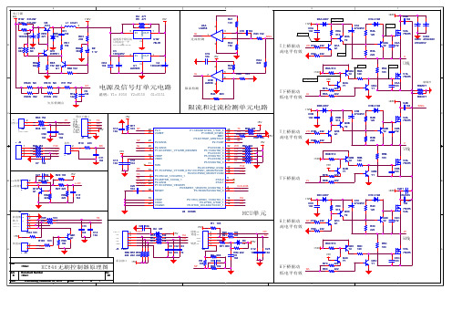
英飞凌 XC846电动车控制器原理图(12管)
康铜丝 R0M KT
R20N 302
R10N 472
U下桥驱动 低电平有效
UL
R8A
R0N KT +48V D0B 4007 +12V C0B 104 R0B 510 Q0B Y2 C1B + 47U/25V R4B 120 Q2B Y2 R3B 222 C2B 272 V2A 75N75 D1B 4148 C4B 104 SING
V下桥驱动
VL
R8B
B
+48V D0C 4007 D1C 4148 C1C + 47U/25V R0C 510 Q0C Y2 R4C 120 Q2C Y2 R3C 222 +12V C0C 104
47U/63V C4C 104 75N75 V4A C2C 272
HA HB HC
J2 GND 防盗低 TB 助力 TA +5V-4 +5V-3 1 2 3 4 5 R24 103 +5V 防盗高
222 222
Q1B G1
V
P2.3/AN3 P1.6/CCPOS1_1/T12HR_0/EXINT6 VDDP VDDC TMS
V线
R6B 510 +12V +5V Q4B Y1 R7B 222 222 C201 + Q5B Y1 C3B 103 Q3B Y2 R9B 120 R5B 103 V3A 75N75
y18050y28550g15551欠压检测点电门锁过流检测限流检测限流和过流检测单元电路康铜丝w线v线u线u上桥驱动高电平有效u下桥驱动低电平有效v下桥驱动w下桥驱动低电平有效v上桥驱动高电平有效w上桥驱动高电平有效mcu单元txrxmbc5vgnd12v60v13v32v0v28v11
常用功率管参数
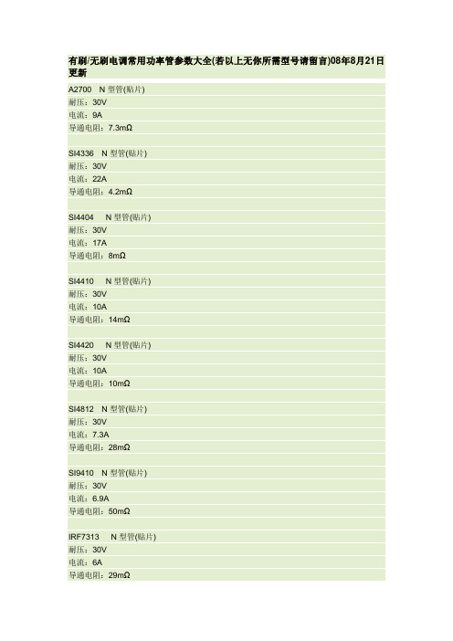
有刷/无刷电调常用功率管参数大全(若以上无你所需型号请留言)08年8月21日更新A2700 N型管(贴片)耐压:30V电流:9A导通电阻:7.3mΩSI4336 N型管(贴片)耐压:30V电流:22A导通电阻:4.2mΩSI4404 N型管(贴片)耐压:30V电流:17A导通电阻:8mΩSI4410 N型管(贴片)耐压:30V电流:10A导通电阻:14mΩSI4420 N型管(贴片)耐压:30V电流:10A导通电阻:10mΩSI4812 N型管(贴片)耐压:30V电流:7.3A导通电阻:28mΩSI9410 N型管(贴片)耐压:30V电流:6.9A导通电阻:50mΩIRF7313 N型管(贴片)耐压:30V电流:6A导通电阻:29mΩIRF7413 N型管(贴片) 耐压:30V电流:12A导通电阻:18mΩIRF7477 N型管(贴片) 耐压:30V电流:11A导通电阻:20mΩIRF7805Z N型管(贴片) 耐压:30V电流:16A导通电阻:6.8mΩIRF7811 N型管(贴片) 耐压:30V电流:11A导通电阻:12mΩIRF7831 N型管(贴片) 耐压:30V电流:16A导通电阻:0.004ΩIRF7832 N型管(贴片) 耐压:30V电流:20A导通电阻:4mΩIRF8113 N型管(贴片)耐压:30V电流:17A导通电阻:5.6mΩTPC8003 N型管(贴片) 耐压:30V电流:12A导通电阻:6mΩFDS6688 N型管(贴片) 耐压:30V电流:16A导通电阻:0.006ΩFDD6688 TO-252贴片耐压:30V电流:84A导通电阻:5mΩA2716 P型管(贴片)耐压:30V电流:7A导通电阻:11.3mΩSI4405 P型管(贴片) 耐压:30V电流:17A导通电阻:7.5mΩSI4425 P型管(贴片)耐压:30V电流:9A导通电阻:19mΩSI4435 P型管(贴片) 耐压:30V电流:8A导通电阻:20mΩSI4463 P型管(贴片)耐压:20V电流:12.3A导通电阻:16mΩSI9435 P型管(贴片) 耐压:30V电流:5.3A导通电阻:50mΩIRF7424 P型管(贴片)电流:8.8A导通电阻:22mΩSTM4439A P型管(贴片) 耐压:30V电流:14A导通电阻:18mΩFDS6679 P型管(贴片) 耐压:30V电流:13A导通电阻:9mΩBUZ111S N型管(直插) 耐压:55V电流:80A导通电阻:8mΩ5N05 N型管(直插)耐压:50V电流:75A导通电阻:0.0095Ω6N60 N型管(直插)耐压:600V电流:5.5A导通电阻:0.75Ω50N03L N型管(直插)耐压:25V电流:28A导通电阻:21mΩ60N06 N型管(直插)耐压:60V电流:60A导通电阻:14mΩBTS110 N型管(直插) 耐压:100V导通电阻:200mΩBTS120 N型管(直插)耐压:100V电流:19A导通电阻:100mΩIRF15 0 N型管(铁壳非直插) 耐压:100V电流:40A导通电阻:55mΩIRF1405 N型管(直插)耐压:55V电流:131A导通电阻:5.3mΩIRF2804 N型管(直插)耐压:40V电流:75A导通电阻:2mΩIRF3205 N型管(直插)耐压:55V电流:110A导通电阻:8mΩIRF3703 N型管(直插)耐压:30V电流:210A导通电阻:2.3mΩIRL3803 N型管(直插)耐压:30V电流:140A导通电阻:6mΩ。
IRF840引脚号
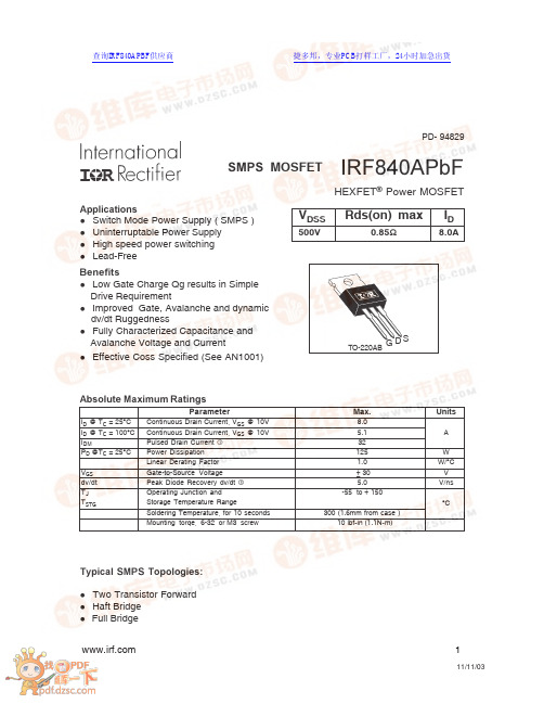
IRF840APbFTO-220ABSMPS MOSFETHEXFET ® Power MOSFETl Switch Mode Power Supply ( SMPS )l Uninterruptable Power Supply l High speed power switching l Lead-FreeBenefitsApplicationsl Low Gate Charge Qg results in Simple Drive Requirementl Improved Gate, Avalanche and dynamic dv/dt Ruggednessl Fully Characterized Capacitance and Avalanche Voltage and CurrentV DSSRds(on) maxI D500V0.85Ω8.0ATypical SMPS Topologies:l Two Transistor Forward l Haft Bridge l Full BridgeParameterMax.UnitsI D @ T C = 25°C Continuous Drain Current, V GS @ 10V 8.0I D @ T C = 100°C Continuous Drain Current, V GS @ 10V 5.1A I DMPulsed Drain Current 32P D @T C = 25°C Power Dissipation 125W Linear Derating Factor 1.0W/°C V GS Gate-to-Source Voltage ± 30V dv/dt Peak Diode Recovery dv/dt 5.0V/ns T J Operating Junction and -55 to + 150T STGStorage Temperature RangeSoldering Temperature, for 10 seconds 300 (1.6mm from case )°CMounting torqe, 6-32 or M3 screw 10 lbf•in (1.1N•m)Absolute Maximum Ratingsl Effective Coss Specified (See AN1001)PD- 94829SD G 查询IRF840APBF供应商捷多邦,专业PCB打样工厂,24小时加急出货IRF840APbFStatic @ T = 25°C (unless otherwise specified)IRF840APbFVs. TemperatureFig 1. Typical Output CharacteristicsIRF840APbFGate-to-Source VoltageDrain-to-Source Voltage Forward Voltage110100100010000100000C , C a p a c i t a n c e (p F )IRF840APbFFig 10a. Switching Time Test CircuitFig 10b. Switching Time WaveformsFig 11. Maximum Effective Transient Thermal Impedance, Junction-to-CaseCase TemperatureV DDV V d(on)rd(off)fIRF840APbFVDSCurrent Sampling ResistorsFig 13b. Gate Charge Test CircuitFig 13a. Basic Gate Charge WaveformFig 12c. Maximum Avalanche EnergyVs. Drain CurrentIV DDFig 12d. Typical Drain-to-Source VoltageVs. Avalanche Current0.01.02.03.04.05.06.07.08.0I AV , Avalanche Current ( A)520540560580600V D S a v , A v a l a n c h e V o l t a g e ( V )IRF840APbFFig 14. For N-Channel HEXFETS* V GS = 5V for Logic Level DevicesPeak Diode Recovery dv/dt Test CircuitV DDIRF840APbFIR WORLD HEADQUARTERS: 233 Kansas St., El Segundo, California 90245, USA Tel: (310) 252-7105TAC Fax: (310) 252-7903Visit us at for sales contact information . 11/03TO-220AB Package Outline。
- 1、下载文档前请自行甄别文档内容的完整性,平台不提供额外的编辑、内容补充、找答案等附加服务。
- 2、"仅部分预览"的文档,不可在线预览部分如存在完整性等问题,可反馈申请退款(可完整预览的文档不适用该条件!)。
- 3、如文档侵犯您的权益,请联系客服反馈,我们会尽快为您处理(人工客服工作时间:9:00-18:30)。
November 2008 Rev 71/12STP80NF12N-channel 120 V , 0.013 Ω, 80 A, TO-220STripFET™ II Power MOSFETFeatures■Exceptional dv/dt capability ■100% avalanche tested■Application oriented characterizationApplication■Switching applicationsDescriptionThis MOSFET series realized withSTMicroelectronics unique ST ripFET process has specifically been designed to minimize input capacitance and gate charge. It is therefore suitable as primary switch in advanced high-efficiency, high-frequency isolated DC-DCconverters for telecom and computer applications. It is also intended for any applications with low gate drive requirements.Type V DSS R DS(on) max I D STP80NF12120 V< 0.018 Ω80 ATable 1.Device summaryOrder code Marking Package Packaging STP80NF12P80NF12TO-220TubeContents STP80NF12Contents1Electrical ratings . . . . . . . . . . . . . . . . . . . . . . . . . . . . . . . . . . . . . . . . . . . . 32Electrical characteristics . . . . . . . . . . . . . . . . . . . . . . . . . . . . . . . . . . . . . 42.1Electrical characteristics (curves) . . . . . . . . . . . . . . . . . . . . . . . . . . . . . 6 3Test circuit . . . . . . . . . . . . . . . . . . . . . . . . . . . . . . . . . . . . . . . . . . . . . . . . 8 4Package mechanical data . . . . . . . . . . . . . . . . . . . . . . . . . . . . . . . . . . . . . 9 5Revision history . . . . . . . . . . . . . . . . . . . . . . . . . . . . . . . . . . . . . . . . . . . 112/12STP80NF12Electrical ratings3/121 Electrical ratingsTable 2.Absolute maximum ratingsSymbol ParameterValue Unit V DS Drain-source voltage (V GS = 0)120V V GS Gate-source voltage± 20V I D (1)1.Limited by PackageDrain current (continuous) at T C = 25 °C 80A I D Drain current (continuous) at T C =100 °C 60A I DM (2)2.Pulse width limited by safe operating area Drain current (pulsed)320A P TOT Total dissipation at T C = 25 °C 300W Derating factor2.0W/°C dv/dt (3)3.I SD < 80 A, di/dt < 300 A/µs, V DD = 80% V (BR)DSS Peak diode recovery voltage slope 10V/ns E AS (4)4. Starting T J = 25 °C, I D = 40 A, V DD = 50 VSingle pulse avalanche energy 350mJ T J T stgOperating junction temperatureStorage temperature-55 to 175°CTable 3.Thermal dataSymbol ParameterValue Unit R thJC Thermal resistance junction-case max 0.5°C/W R thJA Thermal resistance junction-ambient max 62.5°C/W T lMaximum lead temperature for soldering purpose300°CElectrical characteristics STP80NF124/122 Electrical characteristics(T CASE = 25 °C unless otherwise specified)Table 4.On/off statesSymbol ParameterTest conditions Min.Typ.Max.Unit V (BR)DSS Drain-source breakdownvoltageI D = 250 µA, V GS = 0120V I DSS Zero gate voltage drain current (V GS = 0)V DS = Max rating,V DS = Max rating @125°C 110µA µA I GSS Gate body leakage current (V DS = 0)V GS = ±20 V±100nA V GS(th)Gate threshold voltage V DS = V GS , I D = 250 µA 2V R DS(on)Static drain-source on resistanceV GS = 10 V , I D = 40 A0.0130.018ΩTable 5.DynamicSymbol ParameterTest conditions Min.Typ.Max.Unit g fs (1)1.Pulsed: pulse duration=300µs, duty cycle 1.5%Forward transconductance V DS =15 V , I D = 40 A 80S C iss C oss C rss Input capacitance Output capacitance Reverse transfer capacitance V DS =25 V , f=1 MHz, V GS =04300600230pF pF pF Q g Q gs Q gdTotal gate charge Gate-source charge Gate-drain chargeV DD = 80 V , I D = 80 A V GS =10 V1402351189nC nC nCTable 6.Switching timesSymbol ParameterTest conditions Min.Typ.Max.Unit t d(on)t r t d(off)t fTurn-on delay time Rise timeTurn-off delay time Fall timeV DD = 50 V , I D = 40 A, R G =4.7 Ω, V GS =10 V Figure 13 on page 840145134115ns ns ns nsSTP80NF12Electrical characteristics5/12Table 7.Source drain diodeSymbol ParameterTest conditionsMin.Typ.Max Unit I SD Source-drain current 80A I SDM (1)1.Pulse width limited by safe operating area Source-drain current (pulsed)320A V SD (2)2.Pulsed: pulse duration = 300 µs, duty cycle 1.5%Forward on voltage I SD =80 A, V GS =0 1.3V t rr Q rr I RRMReverse recovery time Reverse recovery charge Reverse recovery currentI SD =80 A,di/dt = 100 A/µs,V DD =35 V , T J = 150 °C1550.8511ns µC AElectrical characteristics STP80NF126/122.1 Electrical characteristics (curves)Figure 2.Safe operating area Figure 3.Thermal impedanceFigure 4.Output characteristics Figure 5.Transfer characteristicsFigure 6.Normalized B VDSS vs. temperatureFigure 7.Static drain-source on resistanceSTP80NF12Electrical characteristics7/12Figure 8.Gate charge vs. gate-source voltage Figure 9.Capacitance variationsFigure 10.Normalized gate threshold voltageFigure 11.Normalized on resistance vs.Figure 12.Source-drain diode forwardTest circuit STP80NF128/123 Test circuitFigure 13.Switching times test circuit forFigure 14.Gate charge test circuitFigure 15.Test circuit for inductive loadFigure 16.Unclamped Inductive load testFigure 17.Unclamped inductive waveformSTP80NF12Package mechanical data 4 Package mechanical dataIn order to meet environmental requirements, ST offers these devices in ECOPACK®packages. These packages have a Lead-free second level interconnect. The category ofsecond level interconnect is marked on the package and on the inner box label, incompliance with JEDEC Standard JESD97. The maximum ratings related to solderingconditions are also marked on the inner box label. ECOPACK is an ST trademark.ECOPACK specifications are available at: 9/12Package mechanical data STP80NF1210/12STP80NF12Revision history 11/125 Revision historyTable 8.Revision historyDate RevisionChanges 21-Jun-20042Preliminary version 24-Jul-20063The document has been reformatted, SOA updated 31-Jan-20074T ypo mistake on Table 2.10-Apr-20075T ypo mistake on Table 2 and Table 319-Apr-20076Corrected value on Table 417-Nov-20087Inserted E AS value on Table 2.STP80NF1212/12Please Read Carefully:Information in this document is provided solely in connection with ST products. STMicroelectronics NV and its subsidiaries (“ST”) reserve the right to make changes, corrections, modifications or improvements, to this document, and the products and services described herein at any time, without notice.All ST products are sold pursuant to ST’s terms and conditions of sale.Purchasers are solely responsible for the choice, selection and use of the ST products and services described herein, and ST assumes no liability whatsoever relating to the choice, selection or use of the ST products and services described herein.No license, express or implied, by estoppel or otherwise, to any intellectual property rights is granted under this document. If any part of this document refers to any third party products or services it shall not be deemed a license grant by ST for the use of such third party products or services, or any intellectual property contained therein or considered as a warranty covering the use in any manner whatsoever of such third party products or services or any intellectual property contained therein.UNLESS OTHERWISE SET FORTH IN ST’S TERMS AND CONDITIONS OF SALE ST DISCLAIMS ANY EXPRESS OR IMPLIED WARRANTY WITH RESPECT TO THE USE AND/OR SALE OF ST PRODUCTS INCLUDING WITHOUT LIMITATION IMPLIED WARRANTIES OF MERCHANTABILITY, FITNESS FOR A PARTICULAR PURPOSE (AND THEIR EQUIVALENTS UNDER THE LAWS OF ANY JURISDICTION), OR INFRINGEMENT OF ANY PATENT, COPYRIGHT OR OTHER INTELLECTUAL PROPERTY RIGHT. UNLESS EXPRESSLY APPROVED IN WRITING BY AN AUTHORIZED ST REPRESENTATIVE, ST PRODUCTS ARE NOT RECOMMENDED, AUTHORIZED OR WARRANTED FOR USE IN MILITARY, AIR CRAFT, SPACE, LIFE SAVING, OR LIFE SUSTAINING APPLICATIONS, NOR IN PRODUCTS OR SYSTEMS WHERE FAILURE OR MALFUNCTION MAY RESULT IN PERSONAL INJURY, DEATH, OR SEVERE PROPERTY OR ENVIRONMENTAL DAMAGE. ST PRODUCTS WHICH ARE NOT SPECIFIED AS "AUTOMOTIVE GRADE" MAY ONLY BE USED IN AUTOMOTIVE APPLICATIONS AT USER’S OWN RISK.Resale of ST products with provisions different from the statements and/or technical features set forth in this document shall immediately void any warranty granted by ST for the ST product or service described herein and shall not create or extend in any manner whatsoever, any liability of ST.ST and the ST logo are trademarks or registered trademarks of ST in various countries.Information in this document supersedes and replaces all information previously supplied.The ST logo is a registered trademark of STMicroelectronics. All other names are the property of their respective owners.© 2008 STMicroelectronics - All rights reservedSTMicroelectronics group of companiesAustralia - Belgium - Brazil - Canada - China - Czech Republic - Finland - France - Germany - Hong Kong - India - Israel - Italy - Japan - Malaysia - Malta - Morocco - Singapore - Spain - Sweden - Switzerland - United Kingdom - United States of America。
