epson打印机维修技术手册第一部
打印机维修手册:Epson Stylus Photo PX650_TX650_TX659_PX660_Artisan635_E
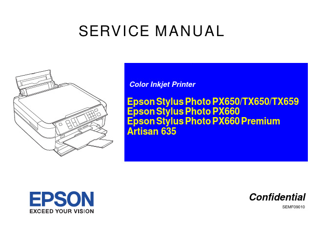
Color Inkjet Printer
Epson Stylus Photo PX650/TX650/TX659 Epson Stylus Photo PX660 Epson Stylus Photo PX660 Premium Artisan 635
Confidential
3. WHEN PERFORMING TESTING AS DICTATED WITHIN THIS MANUAL, DO NOT CONNECT THE UNIT TO A POWER SOURCE UNTIL INSTRUCTED TO DO SO. WHEN THE POWER SUPPLY CABLE MUST BE CONNECTED, USE EXTREME CAUTION IN WORKING ON POWER SUPPLY AND OTHER ELECTRONIC COMPONENTS.
The contents of this manual are subject to change without notice. All effort have been made to ensure the accuracy of the contents of this manual. However, should any errors be detected, SEIKO EPSON would greatly appreciate being
informed of them. The above not withstanding SEIKO EPSON CORPORATION can assume no responsibility for any errors in this manual or the consequences thereof.
Epson 打印机用户手册说明书
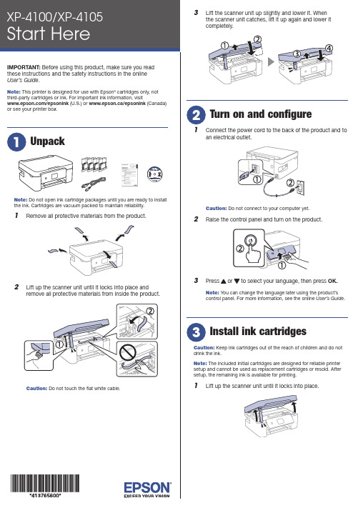
Do not open ink cartridge packages until you are ready to installthe ink. Cartridges are vacuum packed to maintain reliability.emove all protective materials from the product.3 L ift the scanner unit up slightly and lower it. Whenthe scanner unit catches, lift it up again and lower itcompletely.1 C onnect the power cord to the back of the product and toan electrical outlet.Caution: Do not connect to your computer yet.2 R aise the control panel and turn on the product.3 OK.Note: You can change the language later using the product’scontrol panel. For more information, see the online User’s Guide.Caution: Keep ink cartridges out of the reach of children and do notdrink the ink.Note: The included initial cartridges are designed for reliable printersetup and cannot be used as replacement cartridges or resold. Aftersetup, the remaining ink is available for printing.1 L ift up the scanner unit until it locks into place.9 F ollow the on-screen instructions to adjust the printquality of your product.Note:• Y ou need to load paper before you can adjust the print quality.See “Load paper” below for details.• S elect Adjust Later if you want to adjust the print quality later. For more information, see the online User’s Guide.See the online User’s Guide for information about loading capacity, available paper types and sizes, and loading envelopes.1 M ake sure the product is not charging. Then flip thefeeder guard forward, raise the paper support, and tilt itbackwards slightly.2 3 L4 S tightly.5 P6 F ollow the instructions on the LCD screen to select yourpaper settings.• Print from wherever you are, next to your printer or remotely, with Epson Connect™ and Google Cloud Print™. Learn more at /connect (U.S.) or www.epson.ca/connect (Canada).• Use voice-activated assistants to print a variety of creative and everyday items from your Epson product. Simply add your product to an Epson Connect account, then link the account to a voice-activated assistant. See /voice (U.S.) orwww.epson.ca/voice (Canada) for more information.* M ay require the Epson Print Enabler or Mopria Print Service app from Google Play™.Any problems?Network setup was unsuccessful.• M ake sure you select the right network name (SSID).• Restart your router (turn it off and then on), then try toconnect to it again.• T he printer can only connect to a network that supports 2.4 GHz connections. If your router offers both 2.4 GHz and 5 GHz connections, make sure the 2.4 GHz connection is enabled.• I f you see a firewall alert message, click Unblock or Allow to let setup continue.• I f your network has security enabled, make sure you enter your network password (WEP key or WPA passphrase) correctly. Be sure to enter your password in the correct case.AB1# for There are lines or incorrect colors in my printouts.Run a nozzle check to see if there are any gaps in the printout. Then clean the print head, if necessary. See the online User’s Guide for more information.The product’s screen is dark.Make sure your product is turned on, and press any button to wake it from sleep mode.Setup is unable to find my printer after connecting it with a USB cable.Make sure the printer is turned on and that it is securelyconnected as shown:Note:• I f you are using a Mac or your computer does not have a CD/DVD drive, an Internet connection is required to obtain the product software.• T o print from a Chromebook™, go to /support/gcp (U.S.) orwww.epson.ca/support/gcp (Canada) for instructions.Firmware Update Notice: Epson periodically provides firmware updates to address issues of security, performance, minor bug fixes and ensure your printer functions as designed. Your printer was designed to work only with genuine Epson ink cartridges, therefore some updates may affect the functionality of third-party ink.1 M ake sure the product is NOT CONNECTED to yourcomputer.W indows ®: If you see a Found New Hardware screen, click Cancel and disconnect the USB cable.2 I nsert the product CD (Windows only) or download andrun your product’s software package. For the latestsoftware, visit:XP-4100/support/xp4100 (U.S.) www.epson.ca/support/xp4100 (Canada)XP-4105/support/xp4105 (U.S.) www.epson.ca/support/xp4105 (Canada)3 F ollow the instructions on the computer screen to run thesetup program.4 W hen you see the Select Your Connection screen, selectone of the following and follow the on-screen instructions:• Wireless connectionIn most cases, the software installer automatically attempts to set up your wireless connection. If setup is unsuccessful, you may need to enter your network name (SSID) and password.• Direct USB connectionM ake sure you have a USB cable (not included).Mobile and voice-activated printing• Print directly from your iOS device. Simply connect your printer and device to the same network and tap the action icon to select the print option.• Print directly from your Android™ (v4.4 or later) devices*. Simply connect your printer and device to the same networkand tap the menu icon to select the print option.XP-4100/XP-4105 replacement ink cartridges。
Epson 打印机用户手册.pdf_1701927021.181767说明书
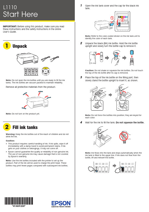
Flashing
On
Initial ink charging may not be complete. Be sure to complete the steps in the “Fill ink tanks” and “Turn on and charge the ink” sections.
Paper is out or multiple pages have fed into the paper support. Load paper correctly in the paper support, then press the button.
Setup is unable to find my product after connecting it with a USB cable. Make sure your product is on and securely connected as shown:
5 Pull out the output tray, then raise the paper stoห้องสมุดไป่ตู้per.
4 Slide the edge guides against the paper, but not too
tightly.
Any problems?
There are lines or incorrect colors in my printouts. Run a nozzle check to see if there are any clogged nozzles. Then clean the print head, if necessary. See the online User’s Guide for more information.
理光复印机维修手册
如何进入SP 模式可以使用下面两种模式:启动SP 模式1. 输入下列键:[Clear Modes] > [1] > [0] > [7]2. 按住[Clear/Stop] 键不放,直到显示SP 模式菜单(约3s 钟)。
启动SSP 模式对于基本型机器(不带可选控制箱的机器),请按下列1 至4 步执行。
对于GDI 机器(带有可选控制箱的机器),请按下列1 至5 步执行。
1. 输入下列键:[Clear Modes] > [1] > [0] > [7]2. 按住键不放,直到显示SP 模式菜单(约3s 钟)。
3. 按住[Enter] 键不放。
4. 在按住[Enter] 键时,请按[1] 键(在数字小键盘上)。
5. 在按住[Enter] 键时,请按"OK"键。
选择程序? 当出现一条闪烁的下划线(或几条闪烁的下划线)时,您可从数字小键盘[D] 输入一个数字。
? 当" /OK" [A] 标记显示在右上角时,您可通过按左箭头[B] 或右键头[C] 来滚动菜单。
若要选中一个程序,请按“OK”键[F]。
指定值1. 在定位一个程序后,请按“OK”键。
闪烁的下划线(或几条闪烁的下划线)指示您可更改的值。
括弧中的值是菜单的默认值。
2. 从数字小键盘输入所需的值。
若要在正值(+)和负值(-)之间切换,请按[./*](句号/星号)键。
3. 若要使该值生效,请按“OK”键。
若要取消该值,请按取消键[E]。
激活复印模式您可在SP 模式正在运行时激活复印模式。
在您这样做时,复印机输出图像或图形,帮助您调整SP 模式程序。
1. 按“ ”键。
复印模式被激活。
2. 指定复印设置,按“OK”键。
3. 若要返回SP 模式,请按“ ”键。
? 您不能在复印模式激活时结束SP 模式。
退出程序/结束(S)SP 模式请按键或“Cancel”键退出该程序。
您可数次按这些键中的一个来结束SP 模式。
Epson 打印机用户手册.pdf_1701924064.594625说明书
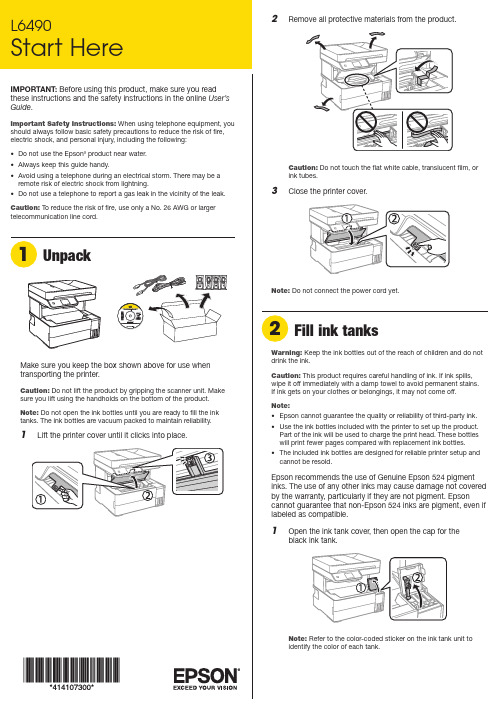
Make sure you keep the box shown above for use when8 Close the ink tank cover.9 C onnect the power cord to the back of the product and toan electrical outlet.Caution: Do not connect to your computer yet.10 P ress thepower button to turn on the product.Note: If an error message appears, turn off the product and check that no protective material has been left inside the product.11 Select your language, country, date, and time settings.Note: You can change these settings later using the product’s control panel. For more information, see the online User’s Guide .Follow steps 12 and 13 to continue ink charging.12 W hen the message to see the Start Here sheet appearson the LCD screen, press and hold the help button for5 seconds.13 W hen the ink confirmation message appears on the LCDscreen, select Done to start charging the ink. Ink charging takes approximately 11 minutes. A message appears when ink charging is complete.Caution: Do not unplug or turn off the product, lift the printer cover, or load paper while the product is charging or you’ll wasteink.Note: After some ink is used for charging, the rest is available forprinting.14 F ollow the on-screen instructions to adjust the printquality.Note: You need to load paper before you can adjust the printquality. See “Load paper” for details.Note:• I f you are using a Mac or your computer does not have a CD/DVD drive, an Internet connection is required to obtain the product software.• T o print from a Chromebook™, go to/support/chromebookprint for instructions.1 M ake sure the product is NOT CONNECTED to yourcomputer.Windows ®: If you see a Found New Hardware screen, click Cancel and disconnect the USB cable.2 I nsert the product CD (Windows only) or download andrun your product’s software package. For the latestsoftware, visit /support/L6490. 3 F ollow the instructions on the computer screen to run the setup program.4 W hen you see the Select Your Connection screen, selectone of the following:• Wireless connectionIn most cases, the software installer automaticallyattempts to set up your wireless connection. If setup is unsuccessful, you may need to enter your network name (SSID) and password.• Direct USB connectionMake sure you have the USB cable ready.• Wired network connectionMake sure you have an Ethernet cable (not included).Mobile printingConnect wirelessly from your smartphone, tablet, or computer.Print documents and photos from across the room or around the world:• P rint directly from your Android™ (v4.4 or later) device*.Simply connect your printer and device to the same network and tap the menu icon to select the print option.• Turn your mobile device into an intuitive, easy-to-useprinting and scanning control center with Epson Smart Panel ®. Download the app from your mobile device’s app store.• Print from wherever you are, next to your printer or remotely, with Epson Connect™. Learn more at /connect* M ay require the Epson Print Enabler or Mopria Print Service app fromGoogle Play™.See the online User’s Guide for information about loading capacity, available paper types and sizes, loading envelopes, and using the rear paper feed slot or ADF .1 M ake sure the product is done charging the ink. Open the2 S3 Insert paper with the printable side down and slide theNote: Make sure the paper is loaded against the front of the cassette.5 S elect the paper settings on the product’s control panel.C onnect the fax line1 C onnect a phone cord to a telephone wall jack and to theLINE port on your product. See the online User’s Guidefor more information.2 S elect Proceed on the LCD screen to set up the fax, orselect Set Up Laterto set it up later.EPSON and Epson Smart Panel are registered trademarks, and EPSON Exceed Your Vision is a registered logomark of Seiko Epson Corporation.Designed for Excellence is a trademark of Epson America, Inc.Windows is a registered trademark of Microsoft Corporation in the United States and/or other countries.Mac is a trademark of Apple Inc., registered in the U.S. and other countries.Android, Chromebook, and Google Play are trademarks of Google LLC.General Notice: Other product names used herein are for identification purposes only and may be trademarks of their respective owners. Epson disclaims any and all rights in those marks.This information is subject to change without notice. © 2020 Epson America, Inc., 12/20CPD-60316Technical supportVisit /support/L6490 to download drivers, view manuals, get FAQs, or contact Epson.You can also speak to a service technician by calling one of these numbers:Argentina(54 11) 5167-0300 Guatemala * 1-800-835-03580800-288-37766Mexico 01-800-087-1080Bolivia * 800-100-116 Mexico City (52 55) 1323-2052Chile (56 2) 2484-3400Nicaragua * 00-1-800-226-0368Colombia 018000-915235Panama * 00-800-052-1376Bogota (57 1) 592-2200Paraguay 009-800-521-0019Costa Rica 800-377-6627Peru 0800-10-126DominicanLima (51 1) 418-0210Republic * 1-888-760-0068Uruguay 00040-5210067Ecuador * 1-800-000-044Venezuela (58 212) 240-1111El Salvador * 800-6570 * C ontact your local phone company to call this toll-free number from a mobilephone.If your country does not appear on the list, contact your nearest Epson sales office. Toll or long distance charges may apply.Need paper and ink?Ensure brilliant results with Epson specialty and plain papers, engineered specifically for Epson printers. You can purchase them from an Epson authorized reseller. To find the nearest one, visit or contact Epson as described in “Any questions?” on this sheet.L6490 replacement inks。
打印机维修手册
打印机维修手册一、常见问题及排查方法1. 打印机不能正常启动•排查方法:先检查打印机是否连接电源,确认电源线插头是否插紧;检查电源线是否损坏或是插座是否工作正常;排除电源问题后,检查打印机的控制面板是否显示正常。
2. 打印质量不佳•排查方法:先检查打印机墨盒是否有墨水,如果是彩色打印机,检查彩色墨盒是否已安装正确;清理打印头和喷嘴,确认打印质量问题是否得到解决。
3. 打印速度过慢•排查方法:检查打印机连接的计算机是否有足够的内存和处理器速度;调整打印机设置,降低打印质量以提高速度;清理打印机内部和喷头,确保其工作正常。
二、维护与保养1. 清洁打印机外壳•定期使用干净的软布擦拭打印机外壳,避免灰尘和污垢影响正常工作。
2. 清洁打印头和喷嘴•使用专用清洁液和软布清洁打印头和喷嘴,确保打印质量和速度。
3. 定期更换墨盒•按照打印机说明书的指引,定期更换墨盒,避免造成打印质量下降或者影响打印机寿命。
三、常见故障解决方案1. 打印机报错代码•解决方案:根据打印机说明书,查询相应的报错代码含义,尝试按照说明书指引排除故障。
2. 打印机卡纸•解决方案:小心打开打印机面板,逐一移除卡纸,避免损坏机器内部零件。
3. 打印机不识别墨盒•解决方案:确认墨盒是否正确安装,检查连接点是否有污垢影响导致不识别,清洁后重新安装。
四、维修注意事项1.尽量避免在打印机工作时拔掉电源或者其他接口线。
2.注意使用专用清洁剂和软布,避免损坏打印机表面。
3.在维修或清洁时,务必先断开电源并等待一段时间确保安全。
五、结语打印机维修手册总结了常见问题的排查方法、维护保养建议以及常见故障解决方案,希望能帮助使用者更好地维护和保养打印机。
若遇到更复杂的故障,请及时咨询专业技术人员或售后服务,以免造成不必要的损失。
EPSON打印机的使用及维修经验
EPSON打印机的使用及维修经验EPSON, 打印机, 经验, 维修《EPSON打印机的使用及维修经验一》在国内的各单位中,EPSON是目前仍在普遍使用的主力打印机,该系列打印机的使用及维修仍是我们必须关注的问题。
笔者在此根据个人及朋友的经验,向大家介绍一些使用及维修的见解,希望能对大家有所帮助。
(一).使用时应注意的事项1.确保使用环境清洁。
使用环境灰尘太多,容易导致字车导轴润滑不好,使打印头的运动受阻,引起打印位置不准确或撞击机械框架造成死机。
有时,这种死机因打印头未回到初始位置,在重新开机时,打印机首先让打印头回到初始位置,接着将进行清洗打印头操作,所以造成墨水不必要的浪费。
解决这个问题的方法是经常将导轴上的灰尘擦掉,并对导轴进行润滑 (选用流动性较好的润滑油,如缝纫机油)。
2.墨盒未使用完时,最好不要取下,以免造成墨水浪费或打印机对墨水的计量失误。
3.关机前,让打印头回到初始位置 (打印机在暂停状态下,打印头自动回到初始位置) 。
有些打印机(如StyluScolor、StylusProXL、MJ-1500K等)在关机前自动将打印头移到初始位置;有些打印机(如MJ-800K、Stylus-1000、StyluScolorⅡ等) 必须在关机前确认处在暂停状态(即“暂停灯”或“Pause”灯亮) 才可关机。
这样做,一是避免下次开机时打印机重新进行清洗打印头操作,浪费墨水;二是因为打印头在初始位置可受到保护罩的密封,使喷头不易堵塞。
4.部分打印机在初始位置时处于机械锁定。
此时如果用手移动打印头,将不能使之离开初始位置。
注意不要强行用力移动打印头,否则将造成打印机机械部分的损坏。
对于像MJ-1500K、 StyluScolor等打印机,在初始位置时打印头处于锁定状态,此时更不要人为移动打印头来更换墨盒,以免引起故障。
5.换墨盒时一定要按照操作手册中的步骤进行,特别注意要在电源打开的状态下进行上述操作。
打印机维修手册
打印机维修手册一、前言打印机是现代办公生活中不可或缺的设备之一。
然而,由于长时间的使用或错误的操作,打印机可能会出现各种故障。
为了帮助用户在面对问题时能够快速有效地解决,本手册将详细介绍常见的打印机故障及其维修方法。
二、故障排查与维修1. 打印质量问题1.1 模糊打印模糊打印是指打印结果中字符或图像没有清晰边缘,模糊不清。
此问题可能由以下原因引起:- 墨盒或碳粉不足,需更换墨盒或碳粉;- 打印头或喷嘴堵塞,需清洁打印头或喷嘴;- 打印纸质量不好,需更换高质量的打印纸。
解决方法:1. 更换墨盒或碳粉;2. 清洁打印头或喷嘴;3. 更换高质量的打印纸。
1.2 斑点或条纹斑点或条纹是指打印结果中出现黑色或彩色小点或线条。
此问题可能由以下原因引起:- 墨盒或碳粉表面有污染物,需清洁墨盒或碳粉;- 打印头或喷嘴堵塞,需清洁打印头或喷嘴;- 墨盒已接近枯竭,需更换墨盒。
解决方法:1. 清洁墨盒或碳粉;2. 清洁打印头或喷嘴;3. 更换墨盒。
2. 纸张进纸问题2.1 多张纸一同进纸多张纸一同进纸是指打印机在进行打印任务时,同时将多张纸张送入打印机。
此问题可能由以下原因引起:- 打印纸张质量不好,需更换高质量的打印纸;- 打印机进纸辊损坏,需更换进纸辊。
解决方法:1. 更换高质量的打印纸;2. 更换进纸辊。
2.2 纸张卡纸纸张卡纸是指打印过程中出现纸张无法正常进纸或进纸困难的情况。
此问题可能由以下原因引起:- 打印纸张放置不正确,需重新调整纸张位置;- 打印纸张质量问题或过于湿润,需更换高质量且干燥的打印纸;- 打印机进纸辊损坏,需更换进纸辊。
解决方法:1. 调整纸张位置,确保放置正确;2. 更换高质量且干燥的打印纸;3. 更换进纸辊。
三、常见故障预防与维护1. 定期清洁打印头或喷嘴定期清洁打印头或喷嘴可以避免堵塞问题的发生,保证打印质量。
可通过打印机自带的清洁程序进行操作,或者使用洗涤液轻轻擦拭打印头或喷嘴。
爱普生EPSON 维修技术手册

打印机技术论坛 感谢上海普广数码科技有限公司提供技术支持 一:清EEPROM及其它面板操作速查(打印机内存全清)针打LQ-300k+换行/换页+进纸/退纸+暂停+电源LX-300+换行/换页+进纸/退纸+暂停+电源LQ-580K:换行/换页+进退纸+暂停+电源.LQ-630K:清EEPROM:换行/换页+进退纸+暂停+电源.设置:进纸/退纸 + 暂停 + 电源键盘锁定:换行/换页 + 暂停 + 5秒以上,响二声。
解锁:进纸/退纸 + 换行/换页 + on.LQ-670K:高速+切纸+电源LQ-680K :换行/换页+进纸/退纸+暂停+电源LQ-1600K3/K3+,2600K字体+切纸+电源LQ-1600K4/K4+字体+切纸+电源LQ-2600K字体 + 切纸 + 电源DLQ-1000K:Line Feed + Form Feed + Micro Adjust↓ + 电源DLQ-3000K:清EEPROM:Selec Type + Paper Select + Pause +电源DLQ-3500K:LF/FF + Load/Eject + Pause + 电源喷墨COLOR切换 + 字体 + 进/退纸 + 暂停+电源COLOR II切换+暂停+进纸+彩清洗+电源COLOR 300进纸+清洗+电源, 再按清洗10秒COLOR 400/440/460进纸灯闪几秒后,按1、 进/退纸清EEPROM2、 清洗10秒,清废墨计数器COLOR 500进纸 + 黑头清洗 + 彩头清洗 + on ,再按进纸键3秒 COLOR 600/640/66O/670进纸+清洗+电源 缺纸灯闪5秒后,再按1、进/退纸清EEPROM及timer IC2、清洗10秒,清废墨计数器COLOR 800/850初始化:进纸+黑头清洗+彩头清洗+ON,松手再按彩头清洗10秒COLOR 1520K切换+进/退纸+换行/换页+微调↑+ 电源COLOR 3000暂停 + 换行/换页 + 微调↓ + 电源SP870/1270进/退纸 + 清洗 + on 然后按1、 /退纸清EEPROM及timer IC2、 清洗10秒,清废墨计数器SP 950:Paper + Roll paper + on 1. Paper (EEPROM)SP 2100/2200Paper + Roll paper + on 1. Paper (EEPROM)MJ-510进/退纸 + 清洗 + on 松手后再按进/退纸10秒至进纸灯和缺墨灯闪MJ-850切换 + 暂停 + 电源, 再按进/退纸至省墨灯与暂停灯闪烁再按切换MJ-1000切换 + 省墨/压缩 + 进/退纸 + 暂停 + 电源MJ-1500K/K+切换+微调↓+暂停+换行/换页+ON激光机EPL-5600:Item+1+Continue+On Line+开机EPL-5700:按切换键+操作继续键+联机键+开机EPL-5700L:操作同EPL-1220(参见1220图示)EPL-5800:按切换键+操作继续键+联机键+开机EPL-5800L:驱动 + 属性→可选设定值 Alt + Ctrl + Shift + W + 鼠标左键EPL-5900&EPL-6100:按住Start/Stop + Job Cancel + Information + 电源,直到联机和错误指示灯同时亮.EPL-5900L&EPL-6100L:1、计算机中选择打印机“属性”中的“可选设定值”项;2、时按住键盘的ALT+CTRL+SHIFT+“W”键,然后用鼠标点击屏幕中“可选设定值”项的任意空白区域,参考EPL-1220图示;3、屏幕出现是否进行EEPROM初始化的对话框,选择“YES“,操作完成。
打印机故障排除维修手册
打印机故障排除维修手册打印机是我们日常工作和生活中常用的办公设备之一,它的故障对我们的工作效率和体验产生了重要影响。
本手册将为大家介绍一些常见的打印机故障,并提供解决方案,以便用户能够自行排除故障和维修打印机。
故障一:打印机不能正常打印1. 检查打印机的电源和电源线是否连接正常,确保电源通电;2. 检查打印队列中是否有未完成的打印任务,如果有,取消任务并重新开始打印;3. 检查打印机与电脑连接线是否松动或损坏,重新连接或更换连接线;4. 检查打印机的墨盒或墨粉是否耗尽,如需要更换,请按照说明书进行操作;5. 清理打印机的喷头或打印机槽,确保没有堵塞或污垢影响打印质量。
故障二:打印机频繁卡纸或纸张无法正常进纸1. 检查打印机的纸张托盘是否放置正确位置,并确保纸张没有弯曲或损坏;2. 清理打印机的进纸器,确保没有纸屑或灰尘阻塞纸张进料;3. 调整打印机的纸张指引器,使得纸张能够顺利进入打印路径;4. 检查纸张类型是否与打印机设置相匹配,如需要更换纸张,请按照说明书进行操作;5. 若上述方法无效,可能是打印机的压纸辊或传动系统出现问题,建议联系专业技术人员进行维修。
故障三:打印机打印质量不佳或出现模糊/花纹现象1. 检查打印机墨盒或墨粉是否过期或存放时间过长,如需要更换,请按照说明书进行操作;2. 进行打印机的喷头清洗操作,使得喷头恢复正常工作;3. 调整打印机的打印质量设置,选择适合的打印模式和纸张类型;4. 校准打印机的颜色设置,确保打印的颜色准确无误;5. 若上述方法无效,可能是打印机的打印头或显影装置出现故障,建议联系专业技术人员进行维修。
故障四:打印机无法正常连接到电脑或无法识别设备1. 检查打印机与电脑的连接线是否松动或损坏,重新连接或更换连接线;2. 检查电脑的USB接口是否正常工作,可尝试连接到其他可用接口;3. 卸载并重新安装打印机的驱动程序,确保驱动程序与操作系统相匹配;4. 检查打印机的设置是否正常,例如是否处于离线状态;5. 若上述方法无效,可能是打印机的接口或控制电路出现故障,建议联系专业技术人员进行维修。
爱普生技术打印机维修必备手册全集讲解
爱普生技术打印机维修必备手册全集第 2 页共 37 页一:清EEPROM 及其它面板操作速查(打印机内存全清)针打LQ-300k+换行/换页+进纸/退纸+暂停+电源LX-300+换行/换页+进纸/退纸+暂停+电源LQ-580K:换行/换页+进退纸+暂停+电源.LQ-630K:清EEPROM:换行/换页+进退纸+暂停+电源.设置:进纸/退纸 + 暂停 + 电源键盘锁定:换行/换页 + 暂停 + 5 秒以上,响二声。
解锁:进纸/退纸 + 换行/换页+ on.LQ-670K:高速+切纸+电源LQ-680K :换行/换页+进纸/退纸+暂停+电源LQ-1600K3/K3+,2600K字体+切纸+电源LQ-1600K4/K4+字体+切纸+电源LQ-2600K字体 + 切纸 + 电源DLQ-1000K:Line Feed + Form Feed + Micro Adjust↓ + 电源DLQ-3000K:清EEPROM:Selec Type + Paper Select + Pause +电源DLQ-3500K:LF/FF + Load/Eject + Pause + 电源喷墨COLOR切换 + 字体 + 进/退纸 + 暂停+电源COLOR II切换+暂停+进纸+彩清洗+电源COLOR 300进纸+清洗+电源,再按清洗10 秒COLOR 400/440/460第 3 页共 37 页进纸灯闪几秒后,按1、进/退纸清EEPROM2、清洗10 秒,清废墨计数器COLOR 500进纸 + 黑头清洗 + 彩头清洗 + on ,再按进纸键3 秒COLOR 600/640/66O/670进纸+清洗+电源缺纸灯闪5 秒后,再按1、进/退纸清EEPROM 及timer IC2、清洗10 秒,清废墨计数器COLOR 800/850初始化:进纸+黑头清洗+彩头清洗+ON,松手再按彩头清洗10 秒COLOR 1520K切换+进/退纸+换行/换页+微调↑+ 电源COLOR 3000暂停 + 换行/换页 + 微调↓ + 电源SP870/1270进/退纸 + 清洗 + on 然后按1、 /退纸清EEPROM 及timer IC2、清洗10 秒,清废墨计数器SP 950:Paper + Roll paper + on 1. Paper (EEPROM)SP 2100/2200Paper + Roll paper + on 1. Paper (EEPROM)MJ-510进/退纸 + 清洗 + on 松手后再按进/退纸10 秒至进纸灯和缺墨灯闪MJ-850切换 + 暂停 + 电源, 再按进/退纸至省墨灯与暂停灯闪烁再按切换MJ-1000切换 + 省墨/压缩 + 进/退纸 + 暂停 + 电源MJ-1500K/K+切换+微调↓+暂停+换行/换页+ON激光机EPL-5600:Item+1+Continue+On Line+开机EPL-5700:按切换键+操作继续键+联机键+开机EPL-5700L:操作同EPL-1220(参见1220 图示)EPL-5800:按切换键+操作继续键+联机键+开机EPL-5800L:驱动 + 属性→可选设定值 Alt + Ctrl + Shift + W + 鼠标左键EPL-5900&EPL-6100:按住Start/Stop + Job Cancel + Information + 电源,直到联机和错误指示灯同时亮. EPL-5900L&EPL-6100L:1、计算机中选择打印机“属性”中的“可选设定值”项;2、时按住键盘的ALT+CTRL+SHIFT+“W”键,然后用鼠标点击屏幕中“可选设定值”项的任意空白区域,参考EPL-1220 图示;3、屏幕出现是否进行EEPROM 初始化的对话框,选择“YES“,操作完成。
StylusC63_C64_C83_C84_维修手册(英文)1

SERVICE MANUALColor Inkjet PrinterEPSON Stylus C63/C64/C83/C84®SEIJ03004NoticeAll rights reserved. No part of this manual may be reproduced, stored in a retrieval system, or transmitted in any form or by any means electronic, mechanical, photocopying, or otherwise, without the prior written permission of SEIKO EPSON CORPORATION.The contents of this manual are subject to change without notice.All effort have been made to ensure the accuracy of the contents of this manual. However, should any errors be detected, SEIKO EPSON would greatly appreciate being informed of them.The above not withstanding SEIKO EPSON CORPORATION can assume no responsibility for any errors in this manual or the consequences thereof.EPSON is a registered trademark of SEIKO EPSON CORPORATION.General Notice:Other product names used herein are for identification purpose only and may be trademarks or registered trademarks of their respec-tive owners. EPSON disclaims any and all rights in those marks.Copyright © 2000 SEIKO EPSON CORPORATION.TPCS Quality Assurance Dept.PRECAUTIONSPrecautionary notations throughout the text are categorized relative to 1)Personal injury and 2) damage to equipment.DANGER Signals a precaution which, if ignored, could result in serious or fatal personal injury. Great caution should be exercised in performing procedures preceded by DANGER Headings.WARNING Signals a precaution which, if ignored, could result in damage to equipment.The precautionary measures itemized below should always be observed when performing repair/maintenance procedures.DANGER1. ALWAYS DISCONNECT THE PRODUCT FROM THE POWER SOURCE AND PERIPHERAL DEVICES PERFORMING ANYMAINTENANCE OR REPAIR PROCEDURES.2. NO WORK SHOULD BE PERFORMED ON THE UNIT BY PERSONS UNFAMILIAR WITH BASIC SAFETY MEASURES AS DICTATEDFOR ALL ELECTRONICS TECHNICIANS IN THEIR LINE OF WORK.3. WHEN PERFORMING TESTING AS DICTATED WITHIN THIS MANUAL, DO NOT CONNECT THE UNIT TO A POWER SOURCE UNTILINSTRUCTED TO DO SO. WHEN THE POWER SUPPLY CABLE MUST BE CONNECTED, USE EXTREME CAUTION IN WORKING ON POWER SUPPLY AND OTHER ELECTRONIC COMPONENTS.4. WHEN DISASSEMBLING OR ASSEMBLING A PRODUCT, MAKE SURE TO WEAR GLOVES TO AVOID INJURIER FROM METAL PARTSWITH SHARP EDGES.WARNING1. REPAIRS ON EPSON PRODUCT SHOULD BE PERFORMED ONLY BY AN EPSON CERTIFIED REPAIR TECHNICIAN.2. MAKE CERTAIN THAT THE SOURCE VOLTAGES IS THE SAME AS THE RATED VOLTAGE, LISTED ON THE SERIAL NUMBER/RATING PLATE. IF THE EPSON PRODUCT HAS A PRIMARY AC RATING DIFFERENT FROM AVAILABLE POWER SOURCE, DO NOT CONNECT IT TO THE POWER SOURCE.3. ALWAYS VERIFY THAT THE EPSON PRODUCT HAS BEEN DISCONNECTED FROM THE POWER SOURCE BEFORE REMOVING ORREPLACING PRINTED CIRCUIT BOARDS AND/OR INDIVIDUAL CHIPS.4. IN ORDER TO PROTECT SENSITIVE MICROPROCESSORS AND CIRCUITRY, USE STATIC DISCHARGE EQUIPMENT, SUCH ASANTI-STATIC WRIST STRAPS, WHEN ACCESSING INTERNAL COMPONENTS.5. REPLACE MALFUNCTIONING COMPONENTS ONLY WITH THOSE COMPONENTS BY THE MANUFACTURE; INTRODUCTION OFSECOND-SOURCE ICs OR OTHER NONAPPROVED COMPONENTS MAY DAMAGE THE PRODUCT AND VOID ANY APPLICABLE EPSON WARRANTY.About This ManualThis manual describes basic functions, theory of electrical and mechanical operations, maintenance and repair procedures of the printer. The instructions and procedures included herein are intended for the experienced repair technicians, and attention should be given to the precautions on the preceding page.Manual Configuration Symbols Used in this ManualThis manual consists of six chapters and Appendix.CHAPTER 1.PRODUCT DESCRIPTIONSProvides a general overview and specifications ofthe product.CHAPTER 2.OPERATING PRINCIPLESDescribes the theory of electrical andmechanical operations of the product.CHAPTER 3.TROUBLESHOOTINGDescribes the step-by-step procedures forthe troubleshooting.CHAPTER 4.DISASSEMBLY / ASSEMBLYDescribes the step-by-step procedures fordisassembling and assembling the product. CHAPTER 5.ADJUSTMENTProvides Epson-approved methods for adjustment. CHAPTER 6.MAINTENANCEProvides preventive maintenance procedures andthe lists of Epson-approved lubricants and adhesivesrequired for servicing the product.CHAPTER 7.APPENDIXProvides the following additional informationfor reference:• Connector pin assignments• Electric circuit boards components layout• Electrical circuit boards schematics• Exploded diagram & Parts List Various symbols are used throughout this manual either to provide additional information on a specific topic or to warn of possible danger present during a procedure or an action. Be aware of all symbols when they are used, and always read NOTE, CAUTION, or WARNING messages.ADJUSTMENT Indicates an operating or maintenance procedure, practice REQUIRED or condition that, if not strictly observed, could result ininjury or loss of life.CAUTION Indicates an operating or maintenance procedure, practice, or condition that, if not strictly observed, could result indamage to, or destruction of, equipment.CHECK May indicate an operating or maintenance procedure,POINT practice or condition that is necessary to accomplish a taskefficiently. It may also provide additional information that isrelated to a specific subject, or comment on the resultsachieved through a previous action.WARNING I.ndicates an operating or maintenance procedure, practice or condition that, if not strictly observed, could result in injuryor loss of life.Indicates that a particular task must be carried outaccording to a certain standard after disassembly andbefore re-assembly, otherwise the quality of thecomponents in question may be adversely affected.Revision StatusRevision Issued Date DescriptionA 2003/7/31 First ReleaseCONTENTSDisassembly and AssemblyOverview (8)Precautions (8)Tools (9)Work Completion Check (10)Caution regarding assembling/disassemblingof the printer mechanism, and how to ensureof quality on re-assembled product (11)Disassembly (12)Housing (Right/Left/Frame), Stacker Assy. removal (13)ASF unit removal (14)Circuit board removal (15)Holder shaft unit removal (17)PS board unit removal (19)CR motor removal (20)Paper guide upper removal (21)Front frame removal (22)CR unit removal (23)Paper eject roller removal (27)Paper guide front removal (28)Printer mechanism/Housing (Lower) removal (29)Ink system removal (32)PF motor removal (33)AdjustmentOverview (35)Required Adjustment (35)Head Angular Adjustment (37)Bi-D Adjustment (37)PF Adjustment (38)PW Adjustment (38)First Dot Adjustment (39)Top Margin Adjustment (39)CR Motor Drive Torque Dispersion Measurement (39)A4 Normal Print and A4 SF Paper Print (39)MaintenanceOverview (41)Cleaning (41)Service Maintenance (41)Lubrication (43)AppendixElectrical Circuits (48)Parts List (48)C H A P T E R DISASSEMBLY AND ASSEMBLYEPSON Stylus C63/64/83/84Revision A 1.1 OverviewThis section describes procedures for disassembling the main components of the Stylus C63/64/83/84. Unless otherwise specified, disassembly units or components can be reassembled by reversing the disassembly procedure. Things, if not strictly observed, that could result in injury or loss of life are described under the heading “Warning”. Precautions for any disassembly or assembly procedures are described under the heading “CAUTION”. Chips for disassembling procedures are described under the heading “CHECK POINT”.If the assembling procedure is different from the reversed procedure of the disassembling, the procedure is described under the heading “REASSEMBLY”.Any adjustments required after reassembling the units are described under the heading “ADJUSTMENT REQUIRED”. When you have to remove any units or parts that are not described in this chapter, refer to the exploded diagrams in the appendix. Read precautions described in the next section before starting.1.1.1 PrecautionsSee the precautions given under the handling “WARNING” and “CAUTION” in the following column when disassembling or assembling EPSON Stylus PC63/64/83/84..WARNING Disconnect the power cable before disassembling or assembling the printer.If you need to work on the printer with power applied, strictlyfollow the instructions in this manual.Wear protective goggles to protect your eyes from ink. If inkgets in your eye, flush the eye with fresh water and see a doctorimmediately.Always wear gloves for disassembly and reassembly to avoidiujury from sharp metal edges.To protect sensitive microprocessors and circuitry, usestatic discharge equipment, such as anti-static wrist straps,when accessing internal components.Never touch the ink or wasted ink with bare hands. If inkcomes into contact with your skin, wash it off with soap andwater immediately. If irritation occurs, contact a physician. WARNING Avant de commencer, assure vous que l’imprimante soit eteinte et que le cordon d’alimentatio n soit debranche.Veillez a jeter les piles usagees selon le reglement local.CAUTION Risque d’explosion si la pile est remplacée incorrectment. Neremplacer que par une pile du même type ou d’un type équivalentrecommandé par le fabricant. Eliminer les piles déchargées selonles lois et les règles de sécurité en vigueur.When transporting the printer after installing the ink cartridge, CAUTIONbe sure to pack the printer for transportation without removingthe ink cartridge.Use only recommended tools for disassembling, assembling oradjusting the printer.Observe the specified torque when tightening screws.Apply lubricants and adhesives as specified. (See Chapter 3for details.)Make the specified adjustments when you disassemble theprinter.(See Chapter 5 for details.)Make sure the tip of the waste ink tube is located at correctposition when reassembling the waste ink tube. Otherwise itwill cause ink leakage.1.1.2 ToolsUse only specified tools to avoid damaging of the printer.Table 1-1. ToolsName Supplier Parts No.Phillips Screw Driver (No.2) EPSON B743800200 Tweezer EPSON B741000100 Hexagon Box DriverEPSON B741700100 (Opposite side : 5.5 mm)1.1.3 Work Completion CheckIf any service is made to the printer, use the checklist shown below to confirm all works are completed properly and the printer is ready to be returned to the user.Table 1-2. Work Completion Check Classifi-Item Check Point Status cationSelf-test Is the operation normal? CheckedNot necessaryOn-line Test Is the printing successful?CheckedNot necessaryPrinthead Is ink discharged normally from Checkedall the nozzles? Not necessary Does it move smoothly?CheckedNot necessary Is there any abnormal noise CheckedCarriageduring its operation? Not necessaryIs there any dirt or foreign Checked MechanismMain Unit objects on the CR Guide Shaft? Not necessaryIs the CR Motor at the correct Checkedtemperature? Not necessary(Not too heated?)• Is paper advanced smoothly?Checked•No paper jamming? Not necessary•No paper skew?Paper Feeding •No multiple feeding? •No abnormal noise?MechanismIs the PF Motor at correct Checkedtemperature? Not necessaryIs the paper path free of any Checkedobstructions? Not necessaryAdjustment Specified Are all the adjustment done CheckedAdjustment correctly? Not necessaryTable 1-2. Work Completion CheckClassifi-Item Check Point StatuscationAre all the lubrication made at CheckedLubricationSpecified the specified points? Not necessaryLubrication Is the amount of lubrication Checkedcorrect? Not necessaryFunction ROM Version Version:CheckedNot necessaryInk CartridgeAre the ink cartridges installed Checkedcorrectly? Not necessaryPackingProtectiveHave all relevant protective Checkedmaterials been attached to theNot necessaryMaterialsprinter?OthersAttachments, Have all the relevant items been CheckedAccessories included in the package? Not necessary1.2Caution regarding assembling/disassemblingof the printer mechanism, and how toensure of quality on re-assembled productOn current low end models, we basically forbided to remove Housing (Lower) from Printer mechanism in your repair. This is because there is a possibility of main frame deformation when a part (such as Ink system) is removed from Printer mechanism without Housing (Lower).Therefore, if you want to replace Ink system/PF motor, we recommend to replace with new Printer mechanism with Housing (Lower).On these models, you have to remove Housing (Lower) from printer mechanism when replacing [Porous Pad] with new one.Therefore, we clarify caution regarding assembling/disassembling of the printer mechanism without Housing (Lower), and how to ensure of quality on repaired productsin this section.[Caution regarding assembling/disassembling of the printer mechanism]1)Main frame(a)Control of assembled standard position.[Reason]The assembed accuracy of each part composed of Printer mechanismis based on Housing (Lower).[Service treatment]Confirm that there is no gap between main frame and Housing (Lower).[Reference]To ensure the assembled accuracy, you have to control the assembledstandard position of main frame against X/Y/Z-axis direction. [X-axis direction]-Make sure that main frame is correctly placed on the groove ofHousing (Lower).-Make sure that there is no gap between main frame and Housing (Lower).[Y-axis direction]Make sure that cut-out portion of main frame is correctly placed on thesquare protrusion of Housing (Lower).[Z-axis direction]-Make sure that there is no gap between main frame and Housing (Lower).-Make sure that the left side of Printer mechanism is correctly fixed bytwo hooks.(b)Control of vertical level of guide rail (Guide rail means the portion latchedby hooks of IC holder & Print head assy..)[Reason]There is a possibility that printing failre/operation failure occurs by guiderail deformation.[Service treatment]-Do not remove [Mounting Plate, M/B] from Printer mechanism.-Hold up the specified position of main frame to avoid the deformation.(c)How to assemble of ASF unit/Circuit board/Paper guide upper[Reason]There is a possibility that main frame deformation is caused extra forcein assembling. As the result, printing failre/operation failure occurs.[Service treatment]Hold the opposite side by by hand while you are installing the above parts.2)Front frame(a)Control of vertical level[Reason]There is a possibility that printing failre occurs by front frame deformation.[Service treatment]Handle Front frame in assembling/disassembling carefully.3)IC holder(a)Handling of IC holder[Reason]If IC holder is damaged in assembling/disassembling of your repair, there isa possibility that vital problem occus in user’s futher operation.[Service treatment]Released two hooks of IC holder from the inside of IC holder by the tweezer. [How to ensure of quality on re-assembled product]We judge that the quality of re-assembled product is ensured if there is noproblem about the print result by adjustment program..1.3 DisassemblyThe flowchart below shows step-by-step disassembly procedures. Whendisassembling each unit, refer to the page number shown in the figure.Housing (Right/Left/Frame), Stacker assy.Page 13*1)ASF unit removal CR motor removal Paper guide upper removal Front frame removal CR unit removal Page 14 Page 20 Page 21 Page 22 Page 23Circuit board removal Holder shaft unit removal Paper eject roller removal Page 15 Page 17 Page 27PS board unit removal Paper guide front removal Page 19 Page 28*2)Printer mechanism/Housing (Lower) removalPage 29Ink system removal PF motor removal Page 32 Page 33 *1) In "Front frame removal", the procedure only for removing Front frame is mentioned.In "CR unit removal, the sequencial procedure of allparts composed of CR unit is mentioned.(Added operations before Front frame removal + Frontframe removal + IC holder +Print head assy. / PW sensor/ CR encoder sensor)*2) There is some cautions regarding repair of these parts.As for the details, please refer to 1.2 "Caution regarding assembling/disassembling of the printer mechanism,and how to ensure of quality on re-assembled product!.Figure 1-1. Disassembling flowchart1.3.1 Housing (Right/Left/Frame), Stacker Assy. removalExternal view2112343455Housing (Left)Housing (Right)Insert metal scale from this slit, and release one hook of I/F cover.This hook is not only the right side but also the left side.DamperFront sideHousing (Frame)BacksideRemoval procedure[Housing (Right/Left/Frame) removal]1) Releasing five hooks by hand/precision screwdriver (-), and remove Housing (Right).2) Release one hook of I/F cover by inserting metal scale vertically from the slit on bottom of Housing (Left), and remove I/F cover.3) Releasing five hooks by hand/precision screwdriver (-), and remove Housing (Left)4) Release five hooks by hand/precision screwdriver (-), and remove Housing (Frame).[Stacker assy. removal]1) Push cut-out portion of Stacker Assy. (left side) by precision screwdriver (-), and pull Stacker assy. to the front side of the printer.Do not damage hooks by hand/precision screwdriver (-) inCAUTIONremoving Housing (Right/Left) & Stacker assy..Do not tilt the printer too much when Housing (Right/Left/Frame) is removed by hand/precision screwdriver (-). This is because ink may possible flow if the cap is not covered by the Print head. (CR is out of the home position)When assembling Housing (Right/Left/Frame) or Stackerassy. to printer mechanism,Hook five ribs for securing Housing cover (Right/Left)1Stacker assy.This marking is the hook that shouldbe removed/installed.This marking is more carefulhooks inassembling/disassembling This marking is the hook portion for Housing cover (Right/Left) andthe order of assembling.to Housing (Right/Left) in the order indicated in thefigure.Make sure that hooks/protrusions of Housing (Right/Left/Frame), Stacker assy., SW bottom and Panel boardis correctly fixed to Housing (Frame/Lower).Make sure that there is not the clearance betweenFigure 1-2. Housing (Right/Left/Frame) and Stacker assy. removalPart/Unit that should be removed before removing Housing (Right/Left/Frame) or Stacker assy..NonHousing (Right/Left/Frame) and Housing (Lower).Make sure that damper for Stacker assy. is correctlyinstalled to the Housing (Lower).1.3.2 ASF unit removalExternal viewScrew type : C.B.P-TITE, 3x8, F/SNOrder of tightening : ThirdThghtening torque : 6±1 kgf.cmScrew type : C.B.S-TITE (P4), 3x6, F/SNOrder of tightening : SecondThghtening torque : 8±1 kgf.cmScrew type : C.B.S SCREW, 3x6, F/SNOrder of tightening : First Thghtening torque : 8±1 kgf.cmASF unit (Backside)Ribs of ASF frame21This marking is1dowel/latched1position and theorder of assembling.3) Release Extension spring 0.585 for Paper return lever, and remove the lever with releasing two protrusions.4) Release Compression spring 1.88 for Returd roller unit, and turn the roller unit until it is free.When assembling ASF unit,Make sure to latch Extension spring 0.585 for Paper return lever & Compression spring 1.88 for Returd roller unit in the order indicated in the figure, and to set Expression spring 0.585 between ribs of ASF frame.Make sure that Paper return lever & Returd roller unit move smoothly.Do not touch returd roller and cork on Hopper.Hook two dowels for securing Paper return lever to ASF frame in the order incicated in the figure.When assembling ASF unit to main frame,2Compression spring 1.88 Extension spring 0.58512Paper return leverFigure 1-3. ASF unit removalPart/Unit that should be removed before removing ASF unitHousing (Right/Left/Frame)ADJUSTMENTREQUIREDMake sure to install Compression spring 2.53 forHopper correctly.Make sure that Hopper moves smoothly.Make sure to set ASF unit with the flat surface of LD roller up.Fasten three screws for securing ASF unit in the order/ tightening torque indicated in the figure.Make sure that there is no gap between ASF unit andShield plate (upper) of PS board unit.When you replace ASF unit with new one, lubricate it with the suitable amount of G-26 grease by the specified position.Removal procedure1) Remove three screws for securing ASF unit to main frame, and remove the unit with pulling up slightly to the backside of the printer.2) Release left protrusion of Hopper by pulling its bottom toward the front side, and remove Hopper from ASF frame.When ASF unit is removed or replaced with new one, the following adjustment must be performed in the order below. 1) Top margin adjustment 2) 1st dot adjustment1.3.3 Circuit board removalExternal view Screw type : C.B.S TITE SCREW, 3x14, F/SNOrder of tightening : FirstThghtening torque : 8±1 kgf.cm Screwtype : C.B.S TITE SCREW, 3x10, F/SNOrder of tightening : Third Thghtening torque : 8±1 kgf.cmScrew type : C.B.S TITE SCREW, 3x6, F/SNOrder of tightening : 4thScrew type : C.B.S TITE SCREW, 3x14, F/SNOrder of tightening : SecondThghtening torque : 8±1 kgf.cmThghtening torque : 8±1 kgf.cmMain board (Backside)Far sideShield Plate FFCHP sideDowel of cramp coreCramp coreFigure 1-4. Circuit boardPart/Unit that should be removed before removing Circuit boardHousing (Right/Left/Frame) / ASF unit Removal procedure1) Remove Clamp core from [Mounting Plate, M/B], and disconnect the following seven cables from the corresponding connectors on main board.- CR motor connector cable : CN5- PF motor connector cable : CN6- Head FFC : CN7, CN8- PE sensor cable : CN9- Power supply connect cable : CN2- Panel board connector cable : CN42) Remove four screws for securing Circuit board to main frame, and remove the board.3) Remove [Shield Plate, M/B] from main board.When assembling Circuit board,Make sure that the metal fittings for locking the Parallel interface is on its shield plate.When assembling Circuit board to main frame,Make sure to connect all cables to the connectors (CN2,CN4, CN5, CN6, CN7, CN8, CN9) on main board in the correct direction.Fasten four screws for securing Circuit board in the order/tightening torque indicated in the figure.Make sure that Shield plate FFC on Head FFC is securely pasted on [Mounting Plate, M/B].Make sure that two dowels of Clamp core is set in home position direction.Make sure that PE sensor cable & CR motor connector cable are set on Holder shaft unit, and in Clamp core.ADJUSTMENT When replacing the Main board with new one, perform the REQUIRED following service items.If the read-out operation succeeds by adjustmentprogram from defective main board, replace withnew board and write the read out data to new one.1)Ink consumption counter2)Waste drain ink pad counter3)Head ID4)Bi-d adjustment5)Top margin adjustment6)1st dot position adjustment7)PW adjustment (Only for SC83/84)8)USB ID9)Market ID10)Head angular adjusstment11)PF adjustmen12)CR motor drive torque dispersion measurementIf the read-out operation is not able to succeed byadjustment program from defective main board,perform the following service items after replacingmain board with new one.1)Replace all ink cartridges with brand-new onefor Ink consumption counter.2)Replace the Waste drain ink pad with new onefor Waste drain ink pad counter.3)Input Head ID4)Adjust Bi-D alignment5)Adjust Top margin6)Adjust 1st dot position7)Adjust PW adjustment8)Input the serial number for USB ID9)Input EEPROM initial setting value for Market ID10)Adjust Head angular11)Adjust PF (Paper feed amount)12)Input max. value of CR motor drivetorque dispersion value1.3.4 Holder shaft unit removalExternal viewThis marking is the hook/protrusion for releasing Holder shaft uni.Removal procedure1) Disconnect Panel board connector cable from the connector on main board, and remove Panel board.2) Remove Clamp core from [Mounting Plate, M/B] and disconnect Head FFC, CR motor connector cable and PE sensor cable from the connector on main board. Then, release Head FFC and CR motor connector cable from Holder shaft unit.Shield plate FFC on Head FFC is pasted on [MountingCAUTIONPlate, M/B]. Therefore, you have to remove Shield plate FFC with Head FFC.Holder shaft unit (Front side)LD roller shaftClatchSpur gear 36.8Tension spring 0.143LD roller shaft unitHP side21Dowel ofcramp coreTorsion spring 0.22Cramp coreHolder shaft unit (Backside)1 2Idle rollerFar sideShield Plate FFCShield Plate FFC3) Release Change lever toward the backside of the printer by the tweezer, and move CR unit to the leftmost side (far side). 4) Remove Holder shaft unit from main frame as belows.Step1) Push two hooks of LD roller shaft holder, and pull Holder shaftunit upward slightly from main frame.Stepe2) Move Pump unit to home position side slightly while holing thewhole of Holder shaft unit, and pull the bottom of the unit toward the backside of the printer.5) Remove LD roller shaft along with Clutch mechanism from LD roller shaft holder.6) Remove the Spur gear 36.8 from LD roller shaft.7) Remove Extension spring, 0.143, and remove Clutch from LD roller shaft. 8) Release one hook for securing PE sensor board, and push the sensor board from the side contacting main frame by the tweezer.9) Release Torsion spring 0.22 for PE detection levers, and remove the lever from LD roller shaft holder.When assembling PE detection lever & sensor board to LD1This marking is the order of assembling.Figure 1-5. Holder shaft unit removalPart/Unit that should be removed before removing Holder shaft unitHousing (Right/Left/Frame) / ASF unitroller shaft holder,Make sure to set Torsion spring 0.22 for PE detectionlever to the suitable position.Make sure that PE detection lever moves smoothly.Make sure that PE sensor board is correctly fixed by theMake sure to place PE sensor cable to the suitablegroove on LD roller shaft holder.When assembling Clutch mechanism to LD roller shaft,Make sure to set the round hole of Clutch on the dowelof LD roller shaft.Do not damage the tooth of Spur gear 36.8 andCombination gear 27.2, 19.2.When assembling Panel board to Holder shaft unit,(This operation is done after installing Holder shaft unitto main frame.)Make sure to set Tension spring 0.143 to the hooks ofClutch and LD roller shaft.Do not set Tension spring 0.143 with twisted condition.Make sure that the Clutch rotates properly.When assembling LD roller shaft to LD roller shaft holder,Do not touch LD roller.When assembling Idle roller to LD roller shaft holder,(This operation is done after all parts composed of Holdershaft unit is assembled to LD roller shaft holder.)When assembling Holder shaft unit to main frame,Make sure that nine hooks of Holder shaft unit arecorrectly fixed.Make sure to place PE sensor cable, CR motorconnector cable and Head FFC on the suitable positionof Holder shaft unit.Make sure to connect PE sensor cable, CR motorconnector cable and Head FFC to the connector (CN5,CN7, CN8, CN9) on main board.Make sure that Shield plate FFC on Head FFC issecurely pasted on [Mounting Plate, M/B].Make sure that two dowels of Clamp core is set in homeposition direction.Make sure that PE sensor cable & CR motor connectorcable are set on Holder shaft unit, and in Clamp core.Do not touch LD roller.ADJUSTMENTREQUIREDMake sure to install Panel board correctly.Make sure to place Panel board connector cable onthe suitable position of Holder shaft unit.When Holder shaft unit is removing or replacing Holdershaft unit with new one, the following adjustment mustbe performed in the order below.1)Top margin adjustment2)1st dot adjustment。
爱普生针式打印机维修手册全集【整理精品范本】
爱普生针式打印机维修手册全集OAZC。
COM 日期:2007-6-4 来源:IT168【IT168 使用技巧】本篇文章是“爱普生针式打印机维修”的下篇,主要是常见爱普生针式打印机的维修实例,对维修具有很大的参考价值,读者朋友可以借鉴学习。
爱普生针式打印机的维修(下)爱普生针式打印机故障实例LQ-300K打印体育****时,使用LQ—300K 打印跳行,但使用1600K 打印正常。
故障分析:1、按照常规方法,进入LQ—300K 打印机的内部设置,查看其自动跳行是否打开,查看结果没有;2、怀疑进纸感应器不太好,更换感应器后,当时打印正常,不跳行,判定为感应器坏,打印一段时间(无规律)仍能出现跳行现象。
3、怀疑主板不好,首先更换主板的EEPROM,更换后也不正常,但一天不到故障依旧,然后更换主板,故障也依旧;4、怀疑电源板供电问题,更换后也一样跳行且时间不规律;5、最后判定PC 主板有问题,更换PC 后,测试无问题,一直至今正常.维修总结:PC 主板能兼容1600K 打印机,未必兼容LQ-300K 打印机.LQ-300K+:关于LQ-300K+打印机常见故障故障现象:打印机在高温20℃以上工作正常,低温8℃左右工作时开机无反应或反应慢(几秒或数分钟后)正常。
诊断与故障排除:就打印机在较高温度下能正常工作,低温下工作不稳定来判断可能是由于低温下电源负载能力低或集成电路功耗****,CPU 检测某部分电路工作状态不稳定而不能正常工作。
常温下测量电源输出——电压、电流、纹波时,纹波偏大。
此时打印机基本正常工作。
而低温下测量电源输出——电压、电源、纹波时,电源5V、3.3V 纹波大(600mv/300mv),线性差。
初步诊断为低温下主控电路功耗大,电源负载能力低,CPU 检测到电源特性差而中断工作。
将5V 电源滤波电容C54(470u/6。
3V)、3.3V 滤波电容C75(47u/35V)更换为C54(1000u/6.3V)、C75(220u/25V)后电源纹波正常(200mv/8mv)。
打印机维修手册:EPL6200_EPL6200L_CH
All effort have been made to ensure the accuracy of the contents of this manual. However, should any errors be detected, SEIKO EPSON would greatly
描述了拆卸和装配产品详细过程 第五章 调试
提供 爱普生认可的调试方法 第六章 维护
提供预防性维护程序 并列出了 爱普生认可的产品服务所需要的 润滑剂和粘结剂 附录 提供以下附加的参考信息 • 接口针分配 • 电路板组件布局 • 电路板简图 • 分解图和零件清单
本册中使用的符号
本手册中使用的各种符号既提供了附加的说明信息 也提供了在操作过程中可 能会出现的危险 请注意用到的所有符号 , 并阅读所有注意 告诫 警告信 息
3. 在按照此手册指导进行测试时 先不要接通部件电源 仅当步骤指示接通电源时再接通电源 连接电源线时 请注意有关电源工作的警告信息和其他电子部件的警告信息
4. 在装配或拆卸设备时 请确保戴手套 以避免被金属部件的边缘划伤
警告
1. 爱普生设备应由爱普生 授权的维修技术人员维修
2. 确保电源电压与设备标注的电压相同 设备电压标注在序列号 / 额定电压标志牌上 如果爱普生产品的原装交流电源额定电压不同于可用电源时 千万不要把设备连接到电源上 3. 拆卸或更换线路板或单个芯片前 检查确保该爱普生 设备已经断电 4. 在进入设备内部操作时 为保护敏感的微处理器和电路 请使用静电消除器具 如防静电护腕等 5. 不要使用非爱普生生产的元件更换故障元器件 , 如果使用未经核准的二级元器件或其它元器件 有可能损害此爱普生产品 , 此情况不在爱普生保修范围内
EPSON 打印机维修手册
另一种造成字车异常的情况是字车电机缺相,判断方法是用手拖动字车,感觉比正常情况
过轻或过重都不正常。
再一种是HP 传感器造成的字车异常,只需更换传感器即可解决问题。
打印头故障维修
断针是打印头比较常见的故障,其原因主要有:
1、 打印强度大,打印量大,自然是造成断针的主要原因;
字体+切纸+电源
LQ-2600K
字体 + 切纸 + 电源
DLQ-1000K:
Line Feed + Form Feed + Micro Adjust↓ + 电源
DLQ-3000K:
清EEPROM:Selec Type + Paper Select + Pause + 电源
DLQ-3500K:
LF/FF + Load/Eject + Pause + 电源
喷墨
COLOR
切换 + 字体 + 进/退纸 + 暂停+电源
COLOR II
切换+暂停+进纸+彩清洗+电源
COLOR 300
进纸+清洗+电源, 再按清洗10 秒
COLOR 400/440/460
EPSON 打印机维修手册
EPL-1220:
1、计算机中选择打印机“属性”中的“可选设定值”项;
2、同时按住键盘的ALT+CTRL+SHIFT+“W”键,然后用点击鼠标左键,参考下图;
屏幕出现是否进行EEPROM 初始的对话框,选择“YES“,操作完成。
EPL-1610K
Epson 打印机用户手册.pdf_1701922418.2931979说明书
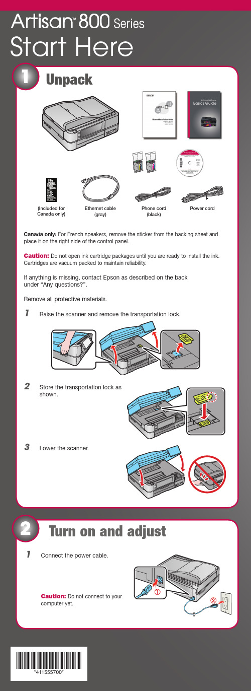
*411555700**411555700*Canada only: For French speakers, remove the sticker from the backing sheet and place it on the right side of the control panel.Caution: Do not open ink cartridge packages until you are ready to install the ink.Cartridges are vacuum packed to maintain reliability.If anything is missing, contact Epson as described on the back under “Any questions?”.Remove all protective materials.1Raise the scanner and remove the transportation lock.2Store the transportation lock as shown.3Lower the scanner.Unpack1Start Here(Included for Canada only)1Connect the power cable.C aution: Do not connect to your computer yet.Turn on and adjust2SeriesEthernet cable(gray)Phone cord (black)Power cordMake settings31Select your language and country.Touch the screen to select the desired option. Press orto see morecountries.2 F or the Daylight Saving Time setting, select Summer if your region usesDaylight Saving Time and it’s currently in effect. (DST is effective fromspring through summer.) Otherwise, select Winter to turn off the setting. Press OK .3Select the date format.4Use the numeric keypad to set the date, then press OK .5Select the time format.6Use the numeric keypad to set the time.7Press OK when done.Note: You can change the date and time settings by pressing the Home button,selecting Setup , selecting Printer Setup , then Date/Time .2Press the On button, then lift the control panel to raise it.To lower the control panel, press the Unlock button.Caution: To avoid damaging your Artisan 800Series, always press the Unlock button to lower the control panel.5Load paperInstall ink cartridges4Note: Don’t load paper before installing the ink cartridges.1 R aise the scanner.2Unpack the ink cartridges.3 Remove only the yellow tape from each cartridge.C aution: Don’t remove any other seals from the cartridges.4 I nsert the cartridges in the holder for each color. Press the cartridgesdown until they click.5Lower the scanner.6Wait while ink charges. Charging takes about 5 minutes.N ote: Your Artisan 800 Series ships with full cartridges. Part of the ink from the first cartridges is used for priming the Artisan 800 Series. Replacement cartridges will print more pages.Caution: Don’t turn off the Artisan 800 Series while the ink system isinitializing or you’ll waste ink.The paper cassette has 2 trays. The main tray is for letter-size, legal-size, or 8 x 10-inch paper. The photo tray is for 4 x 6- or 5 x 7-inch photo paper. 1Pull out the paper cassette. Then slide back the photo tray and lift it up.2 Squeeze the edge guides and slide them out. Then insert paper with theglossy or printable side face-down.3 Slide the edge guides against the paper.4 Lower the photo tray.5 Squeeze the edge guides and slide them out. Then insert 4 x 6-inch or5 x 7-inch photo paper with the glossy or printable side face-down.N ote: Make sure the paper fits under the edge guides.6 Slide the edge guides against the paper.7 Keep the cassette flat as you insert it.8 Extend the output tray and flip up the stopper.Network (wireless or wired)See your Network Installation Guide.You can’t install your software asdescribed below.ORU SB connectionMake sure you have a USB cable (not included).Then follow the steps below.USB connectionFollow these steps to connect the Artisan 800 Series directly to your computer using a USB cable (not included).Windows1 Make sure the Artisan 800 Series isNOT CONNECTED to your computer.Note:If you see a Found New Hardwarescreen, click Cancel and disconnect theUSB cable. You can’t install your softwarethat way.2 Insert the Artisan 800 Series software CD.With Windows Vista, if you see the AutoPlaywindow, click Run Epsetup.exe. When you see theUser Account Control screen, click Continue.3 Click Install and follow the on-screen instructions.To use the Artisan 800 Series for faxing, connect the included phone cord from a telephone wall jack to the LINE port on the Artisan 800 Series. To connect a telephone or answering machine, see the Basics Guide for instructions.Note:If you’re connecting to a DSL phone line, you must use a DSL filter or you won’t be able to fax. Contact your DSL provider for the necessary filter.Connect the phone cord67Choose your connection4 When you see this screen, select Install driver for direct USBconnection and then click Next.5 When prompted, connect a USB cable. Use any open USB port on yourcomputer.Note:If installation doesn’t continue after a moment, make sure yousecurely connected the USB cable and turned on the Artisan 800 Series.6 Follow the on-screen instructions to install the rest of the software andregister your Artisan 800 Series.Be sure to register your Artisan 800 Series to receive these great benefits: 2-year limited warranty and 2-year toll-free customer support.*7 When you’re done, remove the CD.You’re ready to go! Enjoy your Artisan 800 Series! See your Basics Guide oron-screen Epson Information Center for instructions.Macintosh®1 Make sure the Artisan 800 Series is NOT CONNECTED to your computer.2Insert the Artisan 800 Seriessoftware CD.3 Double-click the Epson icon.4 Click Install and follow the on-screen instructions.5 When you see this screen, select Install driver for direct USBconnection and then click Next.Any questions?Basics GuideE asy and quick answers to your questions on printing, copying, scanning, and faxing.On-screen Epson Information CenterC lick the desktop shortcut for easy access to the Artisan 800 Series Epson Information Center , FAQs, online troubleshooting advice, and software downloads. You can also purchase paper and ink.Network Installation GuideInstructions on configuring the Artisan 800 Series for a network.On-screen help with your softwareS elect Help or ? when you’re using your software.Epson Technical Support Internet SupportVisit Epson’s support website at /support and select yourproduct for solutions to common problems. You can download drivers and documentation, get FAQs and troubleshooting advice, or e-mail Epson with your questions.For a video tutorial and other information about setting up a wireless network, go to: /support/wireless Speak to a Support RepresentativeC all (562) 276-4382 (U.S.) or (905) 709-3839 (Canada), 6 AM to 6 PM , Pacific Time, Monday through Friday. Days and hours of support are subject to change without notice. T oll or long distance charges may apply.Software Technical Support ArcSoft Print Creations™ ABBYY ® FineReader ® Sprint Plus/support (510) 226-6717********************6When prompted, connect a USB cable. Use any open USB port on your computer. Make sure the Artisan 800 Series is securely connected and turned on.Mac OS X 10.5 users: skip to step 9. Other users: continue with step 7.7When you see this screen, click Add Printer . Follow the steps on the right side of the screen to add the Artisan 800 Series.8 Click Next again, if necessary.9Follow the on-screen instructions to install the rest of the software and register your Artisan 800 Series.Be sure to register your Artisan 800 Series to receive these great benefits: 2-year limited warranty and 2-year toll-free customer support.*10When you’re done, eject the CD.You’re ready to go! Enjoy your Artisan 800 Series! See your Basics Guide or on-screen Epson Information Center .Need paper and ink?Try Epson premium papers with Claria ® ink for better than lab quality results. For the right supplies at the right time, you can purchase them at Epson Supplies Central SM at /ink3 (U.S. sales) or www.epson.ca (Canadian sales). You can also purchase supplies from an Epson authorized reseller. To find the nearest one, call 800-GO-EPSON (800-463-7766).Genuine Epson PaperEpson offers a wide variety of papers to meet your needs; visit Epson Supplies Central for more information.Ultra Premium Photo Paper Glossy Instant-drying high gloss paper for long-lasting photos, suitable for framing.Genuine Epson InksLook for the numbers below to find your cartridges. It’s as easy as remembering your number!Note: The 98 High Capacity Black (and all 99 Standard Capacity) ink cartridges areavailable online and from Epson authorized resellers. The 98 High Capacity color ink cartridges are available only online; visit /highcapacity (U.S. sales) or www.epson.ca (Canadian sales).Cut out the card to the right and keep it with you when purchasing replacement ink cartridges .Printed in XXXXXXPrinted in XXXXXXInk Cartridges for Artisan ® 800The 98 High Capacity color ink cartridges are available only online;visit /highcapacity (U.S. sales) or www.epson.ca (Canadian sales).ColorStandard capacityHigh capacityBlack—98 Cyan9998 Magenta 9998 Yellow 9998 Light Magenta9998 Light Cyan9998* 1-year limited warranty to all purchasers; 2-year toll-free support and second year warranty require registration within 60 days of purchase. For California and Québec residents, failure to submit this product registration form does not diminish your warranty rights.Epson is a registered trademark, Epson Exceed Your Vision is a registered logomark and Supplies Central is a service mark of Seiko Epson Corporation. Claria is a registered trademark and Artisan is a trademark of Epson America, Inc.General Notice: Other product names used herein are for identification purposes only and may be trademarks of their respective owners. Epson disclaims any and all rights in those marks.This information is subject to change without notice.© 2008 Epson America, Inc. 7/08CPD-25956R1Color Standard capacity High capacityBlack —98Cyan 9998Magenta 9998Yellow 9998Light Magenta 9998Light Cyan9998。
EPSON 打印机维修手册
EPSON 打印机维修手册一:清EEPROM 及其它面板操作速查(打印机内存全清)针打LQ-300k+换行/换页+进纸/退纸+暂停+电源LX-300+换行/换页+进纸/退纸+暂停+电源LQ-580K:换行/换页+进退纸+暂停+电源.LQ-630K:清EEPROM:换行/换页+进退纸+暂停+电源.设置:进纸/退纸+ 暂停+ 电源键盘锁定:换行/换页+ 暂停+ 5 秒以上,响二声。
解锁:进纸/退纸+ 换行/换页+on.LQ-670K:高速+切纸+电源LQ-680K :换行/换页+进纸/退纸+暂停+电源LQ-1600K3/K3+,2600K字体+切纸+电源LQ-1600K4/K4+字体+切纸+电源LQ-2600K字体+ 切纸+ 电源DLQ-1000K:Line Feed + Form Feed + Micro Adjust↓+ 电源DLQ-3000K:清EEPROM:Selec Type + Paper Select + Pause +电源DLQ-3500K:LF/FF + Load/Eject + Pause + 电源喷墨COLOR切换+ 字体+ 进/退纸+ 暂停+电源COLOR II切换+暂停+进纸+彩清洗+电源COLOR 300进纸+清洗+电源,再按清洗10 秒COLOR 400/440/460进纸灯闪几秒后,按1、进/退纸清EEPROM2、清洗10 秒,清废墨计数器COLOR 500进纸+ 黑头清洗+ 彩头清洗+ on ,再按进纸键3 秒COLOR 600/640/66O/670进纸+清洗+电源缺纸灯闪5 秒后,再按1、进/退纸清EEPROM 及timer IC2、清洗10 秒,清废墨计数器COLOR 800/850初始化:进纸+黑头清洗+彩头清洗+ON,松手再按彩头清洗10 秒COLOR 1520K切换+进/退纸+换行/换页+微调↑+ 电源COLOR 3000暂停+ 换行/换页+ 微调↓+ 电源SP870/1270进/退纸+ 清洗+ on 然后按1、/退纸清EEPROM 及timer IC2、清洗10 秒,清废墨计数器SP 950:Paper + Roll paper + on 1. Paper (EEPROM)SP 2100/2200Paper + Roll paper + on 1. Paper (EEPROM)MJ-510进/退纸+ 清洗+ on 松手后再按进/退纸10 秒至进纸灯和缺墨灯闪MJ-850切换+ 暂停+ 电源, 再按进/退纸至省墨灯与暂停灯闪烁再按切换MJ-1000切换+ 省墨/压缩+ 进/退纸+ 暂停+ 电源MJ-1500K/K+切换+微调↓+暂停+换行/换页+ON激光机EPL-5600:Item+1+Continue+On Line+开机EPL-5700:按切换键+操作继续键+联机键+开机EPL-5700L:操作同EPL-1220(参见1220 图示)EPL-5800:按切换键+操作继续键+联机键+开机EPL-5800L:驱动+ 属性→可选设定值Alt + Ctrl + Shift + W + 鼠标左键EPL-5900&EPL-6100:按住Start/Stop + Job Cancel + Information + 电源,直到联机和错误指示灯同时亮.EPL-5900L&EPL-6100L:1、计算机中选择打印机“属性”中的“可选设定值”项;2、时按住键盘的ALT+CTRL+SHIFT+“W”键,然后用鼠标点击屏幕中“可选设定值”项的任意空白区域,参考EPL-1220 图示;3、屏幕出现是否进行EEPROM 初始化的对话框,选择“YES“,操作完成。
- 1、下载文档前请自行甄别文档内容的完整性,平台不提供额外的编辑、内容补充、找答案等附加服务。
- 2、"仅部分预览"的文档,不可在线预览部分如存在完整性等问题,可反馈申请退款(可完整预览的文档不适用该条件!)。
- 3、如文档侵犯您的权益,请联系客服反馈,我们会尽快为您处理(人工客服工作时间:9:00-18:30)。
感谢北京打印机维修网提供技术支持!办公中国-O A 维修技术社区 h t t p ://w w w .p r i n t c h i n a .c n一:清 EEPROM 及其它面板操作速查(打印机内存全清)针打LQ-300k+换行/换页+进纸/退纸+暂停+电源LX-300+换行/换页+进纸/退纸+暂停+电源LQ -580K :换行/换页+进退纸+暂停+电源.LQ-630K :清 EEPROM :换行/换页+进退纸+暂停+电源. 设置: 进纸/退纸 + 暂停 + 电源键盘锁定: 换行/换页 + 暂停 + 5 秒以上,响二声。
解锁: 进纸/退纸 + 换行/换页 + on. LQ-670K :高速+切纸+电源 LQ-680K :换行/换页+进纸/退纸+暂停+电源LQ-1600K3/K3+,2600K字体+切纸+电源 LQ-1600K4/K4+字体+切纸+电源LQ-2600K字体 + 切纸 + 电源 DLQ-1000K :Line Feed + Form Feed + Micro Adjust ↓ + 电源 DLQ-3000K :清 EEPROM :Selec Type + Paper Select + Pause + 电源 DLQ-3500K :LF/FF + Load/Eject + Pause + 电源喷墨COLOR切换 + 字体 + 进/退纸 + 暂停+电源 COLOR II切换+暂停+进纸+彩清洗+电源 COLOR 300进纸+清洗+电源, 再按清洗 10 秒 COLOR 400/440/460办公中国-O A 维修技术社区 h t t p ://w w w .p r i n t c h i n a .c n进纸灯闪几秒后,按1、 进/退纸清 EEPROM2、 清洗 10 秒,清废墨计数器 COLOR 500进纸 + 黑头清洗 + 彩头清洗 + on ,再按进纸键 3 秒COLOR 600/640/66O/670进纸+清洗+电源 缺纸灯闪 5 秒后,再按1、进/退纸清 EEPROM 及 timer IC2、清洗 10 秒,清废墨计数器COLOR 800/850初始化:进纸+黑头清洗+彩头清洗+ON ,松手再按彩头清洗 10 秒 COLOR 1520K切换+进/退纸+换行/换页+微调↑+ 电源 COLOR 3000暂停 + 换行/换页 + 微调↓ + 电源 SP870/1270进/退纸 + 清洗 + on 然后按 1、 /退纸清 EEPROM 及 timer IC 2、 清洗 10 秒,清废墨计数器 SP 950:Paper + Roll paper + on 1. Paper (EEPROM) SP 2100/2200Paper + Roll paper + on 1. Paper (EEPROM)MJ -510进/退纸 + 清洗 + on 松手后再按进/退纸 10 秒至进纸灯和缺墨灯闪 MJ-850切换 + 暂停 + 电源, 再按进/退纸至省墨灯与暂停灯闪烁 再按切换 MJ-1000切换 + 省墨/压缩 + 进/退纸 + 暂停 + 电源 MJ-1500K/K +切换+微调↓+暂停+换行/换页+ON激光机EPL-5600:Item+1+Continue+On Line+开机 EPL-5700:按切换键+操作继续键+联机键+开机 EPL-5700L :操作同 EPL-1220(参见 1220 图示) EPL-5800:按切换键+操作继续键+联机键+开机 EPL-5800L :办公中国-O A 维修技术社区 h t t p ://w w w .p r i n t c h i n a .c n驱动 + 属性→可选设定值 Alt + Ctrl + Shift + W + 鼠标左键EPL-5900&EPL-6100:按住 Start/Stop + Job Cancel + Information + 电源,直到联机和错误指示灯同时亮. EPL-5900L&EPL-6100L :1、 计算机中选择打印机“属性”中的“可选设定值”项;2、 时按住键盘的 ALT+CTRL+SHIFT+“W”键,然后用鼠标点击屏幕中“可选设定值”项的任意空白区域,参考 EPL-1220 图示;3、 屏幕出现是否进行 EEPROM 初始化的对话框,选择“YES“,操作完成。
EPL-6200L : 同上。
EPL-1210:联机 + 继续 + 主菜单 + ON EPL-1220:1、计算机中选择打印机“属性”中的“可选设定值”项;2、同时按住键盘的 ALT+CTRL+SHIFT+“W”键,然后用点击鼠标左键,参考下图; 屏幕出现是否进行 EEPROM 初始的对话框,选择“YES“,操作完成。
办公中国-O A 维修技术社区 h t t p ://w w w .p r i n t c h i n a .c nEPL-1610K联机 + 操作继续 + 主菜单 + 开机EPL-N2000K按 On Line + Continue + Menu 键开机 EPL-N2010联机 + 操作继续 + 主菜单 + 开机 EPL-N2120联机 + 继续 + 菜单 + 电源 EPL-8600K按 On Line + Continue + Menu 键开机直到“FORMAT=EPL8600K”出现EPL-9000K按 On Line + Continue + Menu 键开机直到“FORMAT=EPL8600K”出现 ALC2000:on line + continue + menu selection C8000:联机 + 继续 + 主菜单 + on C8200:联机 + 继续 + 主菜单 + on办公中国-O A 维修技术社区 h t t p ://w w w .p r i n t c h i n a .c n二: 维修经验交流针式打印机针式机的字车异常与喷墨打印机不同,针式机字车异常通常都不用更换字车,但最好的解决方法是将字车轴 取出,擦干净,将油加注到油毡上。
另一种造成字车异常的情况是字车电机缺相,判断方法是用手拖动字车,感觉比正常情况过轻或过重都不正常。
再一种是 HP 传感器造成的字车异常,只需更换传感器即可解决问题。
打印头故障维修断针是打印头比较常见的故障,其原因主要有:1、 打印强度大,打印量大,自然是造成断针的主要原因;2、 打印头脏污,由于长期使用,打印头渡针板间累积油墨与纸屑形成的污物,使其出针受阻,容易折断打印针;3、 色带造成的断针,使用非原装色带或色带使用时间太长,使色带的组织受到破坏,当打印针打到色带上容易将针刮断。
4、 线圈短路:排除线圈本身的质量问题的情况外,主板的针驱动管也是一个主要原因,如针驱动损坏,在换线圈后也要把对应的针驱动管一并更换。
5、 热敏电阻:热敏电阻损坏是非常少的,其表现的故障就象是打印头过热而出的的状况。
针式打印机打印头故障维修打印头故障主要有:打印头断针、打印针线圈烧坏、打印头与打印辊之间的间隙偏离及打印头电缆断线。
1.打印头断针打印头断针是打印机最常见的故障,这种故障几乎占到总故障的一半。
由于打印机的打 印原理是由多根打印针击打色带形成的点阵组成一个字符/汉字。
若打印头中有断针,就会 出现打印的字符/汉字缺点少划。
这里着重介绍几种机型的换针方法: (1)LQ-1600K/ LQ-1900K 打印机1)结构:LQ-1600K 与 LQ-1900K 打印头均为双层针排列结构,针分长、短两种规格,各 l2 根。
2)排列: 打印头 24 根针分奇偶双列,如图1所示。
其中长针为:2,6,10,14,18,22, 3,7,11,l 5,19,23;短针为:4,8,12,l 6,20,24,l ,5,9,l3。
办公中国-O A 维修技术社区 h t t p ://w w w .p r i n t c h i n a .c n换针方法:首先用打印头故障测试程序检查出哪几号针出现故障,然后取下色带盒,翻开打印头锁 定夹,从两边捏住打印头散热片(即外壳),向上提起打印头可以看到连着两根柔性扁平电缆, 拔去电缆便可拿出打印头。
用酒精棉球擦洗打印头前面的墨污,查看一下是否有缺针情况。
若是断针,则需要进行换针。
换针时要准备好工具,主要有镊子、刀片、金刚挫、钢尺、 油石和打印头专用夹具(一种专门用于拆卸打印头散热片的工具)。
用专用夹具退下散热片, 可以看到好几层结构。
将头部朝下,松开定位爪,取下最上面的后铜盖,便可以看到环形分布的 12 根长针,从 测试结果区分出断针是长针还是短针,然后数出所断长针的位置,用镊子取出放在一边;如 果还有短针断针,则继续取出所有长针,再用刀片沿中间的黄色铜垫片下方分开,露出 12 根 短针,用同样方法取出断针。
继而取下一根好针(取长针或短针视所换断针而定),用钢尺精 确测量该针的长度,将新针按所量的尺寸,用金钢挫磨好(注意将针的头部毛刺磨去)后,再 从原位置插入,换好后用手指轻压 12 根针的尾部,使针头从前面探出,此时,应看到 1 号针 和 24 号针位有针露出,而且各列针与针之间应间隔一孔,若有位置插错,必须重新调整。
同 时,当手指放开后各针都能立即收针,保证各针出针畅通。
只有在确认短针全部到位后,才可以安装长针。
在合上铜座之前还要使每针的定位销入 槽,将长针层定位孔合上,检查没有缝隙便可安装长针了。
长针只须照着对应孔位置插下去,长针自尾部到探出头,要经过几道导向槽,最上边的槽孔是很容易穿下去的。
第二道孔稍微 难一些,只要穿过去,针就能顺势而下,很容易到达所在位置。
用拇指压住衔铁,针应露出 1mm ,表示换上去的针是好的。
全部插好后,压上后铜盖,应无缝隙,装好三脚定位爪,套上 散热片,即可上机打印测试。
2.打印针线圈故障由于打印头出针动作是依赖于打印针驱动线圈通电后产生磁场,吸合或释放衔铁而控制 打印针的进退。
若针驱动线圈烧断(开路),则相应的打印针就不出针,因而造成打印缺点少 划;若针驱动线圈短路(击穿),有可能会使整个打印机不工作。
打印针驱动线圈正常与否,一般用万用表的 R×1 挡测量其直流电阻的方法进行鉴别。
几 种常用打印机的打印头针驱动线圈的直流电阻值参见表 1。
下面以 LQ1600K 打印机为例为大家 介绍一下更换线圈的方法。
更换线圈时应按照固定的线圈对应关系(如图 4)找到坏线圈,用小刀切断粘结在线圈架上的明 胶,再用镊子和电烙铁取出线圈。
拆下坏线圈时要注意不要将相邻的好线圈碰坏,装线圈时 应注意线圈的引脚不要和铁壳相碰。
最后用明胶固定好线圈。
打印头修好后,按照拆卸时的逆顺序将打印头恢复。
