CN_R449 ,R726技术手册
国控精仪PCI PXI PCIe-7265 250kS s数据采集卡用户手册说明书

PCI/PXI/PCIe-7265 250kS/s隔离单端48路/差分24路轮询模拟量输入2路任意波形发生8路可编程数字量IO多功能数据采集卡用户手册版本号:Q7-30-02修订日期:2017-1-12国控精仪(北京)科技有限公司2017年版权所有本软件文档及相关套件均属国控精仪(北京)科技有限公司所有,包含专利信息,其知识产权受国家法律保护,除非本公司书面授权许可,其他公司、组织不得非法使用和拷贝。
为提高产品的性能、可靠性,本文档中的信息如有完善或修改,恕不另行通知,客户可从公司网站下载或致电我们通过电子邮件索取,制造商无需作成承诺和承担责任。
客户使用产品和软件文档进行设备调试和生产时,应进行可靠性、功能性等全面测试,方可进行整体设备的运行或交付。
我们提供7*24电话技术支持服务,及时解答客户问题。
如何从国控精仪获得技术服务我们将为客户提供满意全面的技术服务。
请您通过以下信息联系我们。
国控精仪公司信息网址: 英文中文销售服务: **************电话: 400 9936 400、************传真: ************地址: 北京市海淀区安宁庄东路18号2号办公楼420-423室请将您下列的信息通过邮件或传真发送给我们目录1概述...................................................................................................................................... - 1 -1.1产品特性.................................................................................................................. - 1 -1.2产品应用.................................................................................................................. - 2 -1.3产品详细指标.......................................................................................................... - 2 -1.3.1模拟量输入(AI) ........................................................................................... - 2 -1.3.2通用数字IO................................................................................................. - 4 -1.3.3通用定时计数器.......................................................................................... - 5 -1.3.4模拟量触发(A.Trig) ............................................................................... - 5 -1.3.5数字量触发(D.Trig) ............................................................................... - 6 -1.3.6设备同步接口.............................................................................................. - 6 -1.3.7系统稳定时间.............................................................................................. - 6 -1.3.8物理特征...................................................................................................... - 6 -1.3.9产品功耗(典型值) ..................................................................................... - 7 -1.3.10工作环境...................................................................................................... - 7 -1.3.11存储环境...................................................................................................... - 7 -1.4软件支持.................................................................................................................. - 7 -2设备安装.............................................................................................................................. - 9 -2.1产品开箱.................................................................................................................. - 9 -2.2软件安装.................................................................................................................. - 9 -2.3产品布局图............................................................................................................ - 10 -2.4产品硬件配置........................................................................................................ - 11 -3信号连接说明.................................................................................................................... - 13 -3.1连接器管脚分配.................................................................................................... - 13 -3.2模拟量输入的信号连接方式................................................................................ - 16 -3.2.1信号源类型................................................................................................ - 16 -3.2.2单端连接方式............................................................................................ - 16 -3.2.3差分连接方式............................................................................................ - 17 -4产品功能详细介绍............................................................................................................ - 19 -4.1AI 转换 ................................................................................................................. - 19 -4.1.1AI数据获取模式....................................................................................... - 19 -4.1.2AI数据格式............................................................................................... - 20 -4.1.3时钟源相关................................................................................................ - 21 -4.1.4AI启动方式............................................................................................... - 22 -4.1.5触发功能.................................................................................................... - 22 -4.1.6DMA数据传输功能 ................................................................................. - 27 -4.2数字量输入、输出................................................................................................ - 28 -4.2.1方向控制.................................................................................................... - 28 -4.2.2电气特性.................................................................................................... - 28 -4.3计数器.................................................................................................................... - 28 -4.3.1方式0:计数模式0;.............................................................................. - 29 -4.3.2方式1:计数模式1;.............................................................................. - 29 -4.3.3方式2:频率周期模式0;...................................................................... - 29 -4.3.4方式3:频率周期模式1;...................................................................... - 30 -4.3.5方式4:频率周期模式2;...................................................................... - 30 -4.3.6方式5:脉冲发生模式0;...................................................................... - 31 -4.3.7方式6:脉冲发生模式1;...................................................................... - 31 -4.3.8方式7:脉冲发生模式2;...................................................................... - 32 -5产品校准............................................................................................................................ - 33 -图目录图2-1 PCI-7265产品布局图........................................................................................ - 10 -图2-2 PXI-7265产品布局图........................................................................................ - 11 -图2-3 PCIe-7265产品布局图 ...................................................................................... - 11 -图3-1 端子示意图 ........................................................................................................ - 13 -图 3-2 单端连接方式.................................................................................................... - 17 -图3-3 差分连接方式 .................................................................................................... - 18 -图4-1 AI工作时钟 ....................................................................................................... - 21 -图 4-2 预触发模式........................................................................................................ - 24 -图 4-3 后触发模式........................................................................................................ - 24 -图4-4 延时触发模式 .................................................................................................... - 25 -图 4-5 中间触发模式.................................................................................................... - 25 -图4-6 中间触发触发点分割数据 ................................................................................ - 26 -图4-7 持续触发模式 .................................................................................................... - 26 -图4-8 窗触发 ................................................................................................................ - 27 -图 4-9 重复触发............................................................................................................ - 27 -图4-19 计数模式0 ....................................................................................................... - 29 -图 4-20 计数模式1....................................................................................................... - 29 -图 4-21 频率周期模式0............................................................................................... - 30 -图 4-22 频率周期模式1............................................................................................... - 30 -图 4-23 频率周期模式2............................................................................................... - 31 -图 4-24 脉冲发生模式0............................................................................................... - 31 -图 4-25 脉冲发生模式1............................................................................................... - 32 -图4-26 脉冲发生模式2 ............................................................................................... - 32 -表目录表1-1 -3dB 小信号带宽 ................................................................................................ - 3 -表1-2 Spurious-Free Dynamic Range ............................................................................. - 3 -表1-3 Signal-to-Noise Ratio ........................................................................................... - 3 -表1-4 Total Harmonic Distortion .................................................................................... - 3 -表1-5 Signal-to-(Noise + Distortion) .............................................................................. - 3 -表1-6 Differential Linearity Error ................................................................................... - 3 -表1-7 Integral Linearity Error ......................................................................................... - 4 -表1-8 Gain Error ............................................................................................................. - 4 -表1-9 Offset Error ........................................................................................................... - 4 -表3-1 68-pin scsi接口定义.......................................................................................... - 14 -表3-2 68-pin scsi接口说明.......................................................................................... - 15 -表3-3 20-pin DSI接口定义.......................................................................................... - 15 -表3-4 20-pin DSI接口说明.......................................................................................... - 16 -表4-1 AI双极性量程及码值 ....................................................................................... - 21 -1概述PCI/PXI-7265是基于32位PCI架构的高性能数据采集卡,PCIe-7265是基于PCI Express 1X架构的高性能数据采集卡。
SOPC实验指导书(EP2C20Q240C8)

目录目录 (1)第一章系统的硬件单元及使用说明 (2)一、本实验箱的结构特点: (2)二、各模块电路说明: (3)1、数码管显示模块 (3)2、AD 转换模块 (3)3、DA 转换模块 (4)4、以太网模块 (4)6、VGA接口模块 (5)7、PS/2接口模块 (6)8、串行接口模块 (6)9、开关量输入输出模块 (7)10、按键模块 (7)11、LED 灯指示模块 (8)12、音频接口模块 (8)13、TFT液晶接口模块 (9)14、USB接口电路 (9)第二章QUARTUS II和NIOS II 软件的使用方法 (10)一、Q UARTUS II软件的使用方法 (10)二、SOPC B UILDER /N IOS II IDE软件使用方法 (19)第三章VHDL基本程序设计实验 (27)实验一组合逻辑半加器的设计 (27)实验二使用VHDL设计组合逻辑全加器 (34)实验三带进位输入的8位加法器 (40)实验四全减器 (43)实验五四位向量加法/减法器 (46)实验六组合逻辑3-8译码器的设计 (48)实验七数据比较器 (51)实验八多路数据选择器 (53)实验九编码器 (56)实验十计数器 (59)实验十一7段数码管控制接口 (62)实验十二16*16点阵设计 (64)实验十三MOORE机 (68)实验十四MEALY机 (71)实验十五D/A接口 (74)实验十六A/D接口 (76)第一章系统的硬件单元及使用说明一、本实验箱的结构特点:1、系统构成SOPC综合实验系统开发实验平台采用ALTERA Cyclone II EP2C20处理器,集众多功能于一体,采用全新的"主控制板+……+核心板+平台主板"自由组合式结构。
根据实验研发需求,可实现基于ALTERA、XILINX、ACTEL、Lattice等厂家的软核/硬核处理器相结合的嵌入式系统设计。
本实验系统实验平台功能强大,硬件接口丰富,平台嵌入式软件除支持C、C++语言开发之外,还支持uC/OS II、uClinux嵌入式操作系统。
热回收转轮 操作和维护手册说明书

热回收转轮操作和维护手册DTR-VS-ver.5.0 (09.2017)IEC/EN 60439-1 +AC Low voltage switchgears and controllersVTS 保留非预先通知而修改的权利目录1. 介绍 (2)2. 技术数据 (3)2.1. 驱动单元基本参数 (3)2.1.1. 结构 (3)2.1.2. 驱动器操作 (3)2.2. 技术规范 (4)2.2.1. 结构 (4)2.2.2. 操作参数 (4)2.2.3. 元器件的额定参数 (4)2.3. 驱动单元的安装和配置 (5)2.4. 含变频器和VTS自控的驱动单元安装和配置 (5)2.4.1. 热回收转轮驱动回路的接线图 (5)2.4.2. 驱动单元的安装和配置 (6)2.4.3. 电机防护 (7)2.5. 自控系统的驱动单元安装和配置 (7)2.5.1. 热回收转轮驱动回路的接线图 (7)2.5.2. 热回收转轮驱动单元的控制 (8)2.5.3. 变频器配置例子 (8)2.5.4. 电机保护 (9)2.6. 系统中带有EC调速器的驱动单元安装和配置 (10)2.6.1. EC调节器的ModBus RTU/RS485参数 (11)2.6.2. 通过MODBUS设置旋转速度 (12)2.7. 安装建议 (13)3. 保存和运输 (14)4. 启动 (14)5. 维护 (15)5.1. 热回收转轮和驱动皮带 (15)5.2. 转轮密封 (16)1. 介绍本文档描述了关于热回收转轮的参数、运输、保管和服务内容。
●在进行任何动作前,务必详细阅读本文档。
2. 技术数据2.1. 驱动单元基本参数2.1.1. 结构本驱动单元是每个热回收转轮的完整部件。
基本构成如下:●变频器/EC电机控制器(取决于不同的版本或区域)●热回收轮芯●轮芯驱动皮带传动装置●电机减速器-马达带有减速齿轮2.1.2. 驱动器操作驱动单元用于启动并平缓地控制热回收转轮,使得速度在3-10rpm范围内。
瑞斯康达综合业务交叉复用设备用户使用手册200906

RC3000-SUB-D485 RC3000-SUB-DSR(-48V)
RC3000-SUB-DETHB
高双权修改 高双权修改 高双权修改 高双权修改
2008-6-24 2008-11-20 2009-3-18 2009-06-30
200806 200811 200903 200906
5.1 RC3000 主机功能和使用说明: ..................................... 18 5.1.1 出厂默认设置: ............................................ 18 5.1.2 设备的自检启动: .......................................... 18 5.1.3 在出厂默认设置状态下,设备自动生成设置说明: .............. 18 5.1.4 工作时钟的自动切换说明: .................................. 19 5.1.5 自动生成交叉设置说明: .................................... 19 5.1.6 系统和交叉设置说明: ...................................... 20 5.1.7 设备告警内容说明: ........................................ 20 5.1.8 网管通道说明: ............................................ 21 5.1.9 端口的定义说明: .......................................... 22
nt96675技术手册

nt96675技术手册
(原创版)
目录
1.NT96675 技术手册概述
2.NT96675 技术手册的主要内容
3.NT96675 技术手册的适用对象
4.NT96675 技术手册的价值和意义
正文
T96675 技术手册是一本关于 NT96675 技术的详尽指南,它包含了NT96675 技术的各个方面,从基础理论到实际应用,从技术细节到操作步骤,为广大技术工作者提供了宝贵的参考资料。
T96675 技术手册的主要内容包括:NT96675 技术的发展历程、基本原理、技术特点、应用领域等。
其中,NT96675 技术的发展历程部分详细介绍了 NT96675 技术从诞生到发展的整个过程,基本原理部分则深入浅出地解释了 NT96675 技术的工作原理,技术特点部分则从各个角度全面地描述了 NT96675 技术的优势和特点,应用领域部分则列举了 NT96675 技术在各个行业的具体应用。
T96675 技术手册的适用对象主要是技术工作者,包括科研人员、工程师、技术人员等。
他们可以通过学习这本手册,全面地了解和掌握
NT96675 技术,从而更好地应用到实际工作中。
T96675 技术手册的价值和意义在于,它不仅提供了 NT96675 技术的全面知识,而且以实际应用为例,让学习者能够更好地理解和应用
NT96675 技术。
第1页共1页。
RC4中文操作手册

手册引导内容提要1介绍1.1手册结构1.2补充文件1.3操作手册使用人群1.4手册中使用的信号和警示1.5使用的方式和缩写1.6版本附件2设备描述2.1目的2.2潜在的危险3总述3.1电源3.2外加24VDC3.3使用的电缆型号3.4安全须知3.4.1Congrav RC-4使用安全须知3.4.2安装安全须知3.4.3接线安全须知3.4.4使用和操作安全须知4硬件描述4.1Congrav RC-4:类型4.2Congrav RC-4A:显示和按键4.2.1集成按键及其功能4.2.2显示和功能组成4.3参数更改4.3.1数字输入4.3.2固定参数设置的选择4.3.3如果….,更改参数不被接受4.4Congrav RC-4B:4.5Congrav RC-4的插卡槽4.5.1现场的可能连线4.6Congrav RC-4的基本功能4.6.1插入卡RC4-MSIO4.6.1.1XS1.1:与主计算机的连接4.6.1.2XS1.2:与ISC现场总线的连接4.6.1.3XS1.3:与调试解调器和工控电脑的连接4.7Congrav RC-4的选项卡4.7.1CDIO插入卡4.7.2DIOP插入卡4.7.2.1输入输出模式-数字式RC-4的终端功能4.7.3ANOP插入卡4.7.3.1输入输出模式-模拟式RC-4的终端功能4.7.4Profibus模式5调试5.1安装5.2调试,Congrav RC-4的开机5.3Congrav RC-4:软件升级5.4ISC-CM:软件升级6菜单页F100安装结构6.1F110:安装模式6.2模拟结构6.3F120:主计算机操作6.4F130:显示内容改变6.5连锁停机6.6时间和日期6.7F150:配方处理6.7.1设定值斜线,设定值阈值6.7.2调试操作7F200:打印机结构,内存值重设7.1打印功能7.2F210:如何清除记忆内容8F300:设定值输入和选择8.1安装设定值8.2加料器设定值8.2.1`设定值的模拟控制8.2.2设定值斜线,设定值阈值(菜单页F150)8.3选项8.4F310:滞后时间8.5报警停机9F400:安装的实际值,总产量重设9.1F430:总产量重设10单台加料器操作10.1加料器页的抬头10.2Kxx0:加料器控制10.3操作功能10.3.1开机5410.3.2停机5410.3.3报警重设10.3.4补料5510.3.5删除5510.3.6开始试样10.3.7开始去皮10.3.8右侧行实际值的显示10.4Kxx1:产品参数10.4.1自动去皮10.4.2检查最大输出10.4.3堆积密度10.4.4体积最大输出10.4.5十进制转换10.4.5.1十进制转换的设置10.4.6模式5910.4.6.1失重式加料(GF)10.4.6.2体积式控制(VR)10.4.6.3体积式设置(VS)10.4.6.4排料(DI)10.4.6.5检查最大输出(CM)10.4.6.6重量式排料(GD)10.4.6.7体积式加料(VF)10.4.6.8测量(M)10.4.6.9运行过程中GF和VF模式转换10.5Kxx2:控制参数10.5.1PID控制的设置10.5.1.1控制成套配合10.5.1.2重量式计算最大输出10.5.1.2.1CM值的存储11F500:报警报告和开机条件11.1报警报告11.2缺省的开机条件11.3系列驱动控制操作的错误代码11.3.1系列变频器11.3.2振动放大器控制器ISC-VC 11.4Kxx5:报警结构12硬件结构12.1 Kxx8:ISC-CM(-A)的硬件结构12.1.1 速度输入12.1.2 传感器(重量读取)的结构12.1.3 驱动控制器12.1.4 ISC-CM-A模拟输入输出的结构12.1.4.1 ISC-CM-A上单台控制的选项12.1.4.2 Kxx8:模拟输入12.1.4.3 Kxx8:模拟输出12.2 ANOP模拟输入输出的结构12.2.1 安装控制和安装的实际值12.2.1.1 菜单页F190的参数12.2.2 ANOP的组分功能12.2.2.1 模拟输入:模拟单台控制12.2.2.2 模拟输出:总操纵量或实际值12.2.2.2.1 模拟输出信号范围的定义12.3 CDIO的数字输入输出12.4 DIOP的数字输入输出12.4.1 DIOP:功能描述12.5 ISC现场总线机构12.5.1 如果构建总线通讯12.5.2 总线通讯的关闭12.6 调试解调器的机构12.7 主计算机操作机构12.7.1 MISO卡上的主计算机接口12.7.2 Profibus DP操作结构12.7.3 以太网接口的结构13校正程序13.1加料器参数13.2加料器参数功能解释13.2.1CP02-加料范围13.2.2CP04-欠载13.2.3CP03-最大输出量13.2.4CP05-过载13.2.5CP06-粗去皮13.2.6CP07-平均重量取数13.2.7CP08-总产量累计分值13.2.8CP09-最小速度13.2.9CP010-最大速度13.2.10CP11-控制偏差13.2.11CP12-报警停机滞后时间13.2.12CP13-联锁类型13.2.13CP14-实际值指示13.2.14CP15-杠杆臂值13.2.15CP16-料斗内容13.2.16CP17-最小补料料位13.2.17CP18-最大补料料位13.2.18CP19-Window/K1/滤波IDL/F, AED 13.2.19CP20-数字速度13.2.19.1标准速度监控13.2.19.2FlexWall-Plus加料器的运动监控13.2.19.3数字式速度取数13.2.19.4推荐输入13.2.20CP21-最大补料时间13.2.21CP22-补料优化13.2.22CP23-稳定时间13.2.23CP24-测样时间13.2.24CP25-防振(A V)切断时间13.2.25CP26-PID控制器接近时间13.2.26CP27-控制器自动化13.2.26.1控制器自动化13.2.26.2开机自动化13.2.26.2.1重复的开机自动化13.2.26.2.2总体开机自动化13.2.27CP28-滤波限制13.2.28CP29-实际值的接纳13.2.29CP30-总操纵量的接纳13.2.30CP31-体积控制(VR)实际值的接纳13.2.31CP32-开机滞后时间13.2.32CP33-称重桥(LWB)的长度13.2.33CP34-重量测试值(WTV)13.2.34CP35-摄取(AP)13.2.35CP36-自动去皮范围13.2.36CP37-无负载时间自动去皮13.2.37CP38-有比例的皮带速度13.2.38CP39-皮带长度13.2.39CP40-dead time way13.3附加参数13.3.1AP01-05 校正13.3.2AP11-可用的称重范围13.3.3AP12-drop out13.3.4AP13-速度模式13.3.5AP14-滑动影响13.3.6AP15-滑动值13.3.7AP16-速度接纳性13.3.8AP17-无负载时间13.3.9AP18-AT时间13.3.10AP19-驱动控制2最小13.3.11AP20-驱动控制2最大14硬件测试功能14.1F140:输入输出测试-外围(安装)14.2Kxx3:输入输出状态显示-外围14.3Kxx4:测试功能和模拟14.3.1模拟模式14.3.2输入输出测试(加料器)15名词解释附件11915.1技术数据15.2电磁兼容性15.3零配件清单15.4可能显示的模式清单15.5菜单页清单插图表图4-1:Congrav RC-4后部视图图4-2:Congrav RC-4后部视图(带ProfiBus模式)1 总介绍1.1手册的结构现有的操作手册包括:RC-4的:●技术操作和●RC-4 HGC软件(其版本请参见封页)按照下列顺序,每章独立描述一个完整的主题:●设备的描述●使用特性●硬件执行●硬件功能定义●操作●软件描述●参数描述和●结构例举1.2附加文件●ISC系统的描述●ISC-CM,ISC-FC和ISC-VC的技术手册●相应主计算机程序手册1.3操作手册所适用的人群操作手册适用于以下两组人群:●经过授权和培训过的专业技术人员来进行安装和其它电气工作。
EtherCAT使用手册_1.07

修改附录 A
修改附录 D
修改 Pn006、Pn510、Pn511、Pn513、Pn517、 Pn528
增加 ProNet-□□□EG-EC 产品
增加 5.16 绝对值编码器的设置(Fn010、 Fn011)
增加 5.17 单位换算单元
EtherCAT 使用手册
目录
1 EtherCAT 简介 ......................................................................................................... 1 1.1 何谓 EtherCAT ............................................................................................... 1 1.2 EtherCAT 概况................................................................................................ 1 1.3 产品概述......................................................................................................... 1 1.4 CoE 技术术语.................................................................................................. 1 1.5 数据类型......................................................................................................... 2 1.6 通讯规格......................................................................................................... 3 1.7 LED 指示灯 ..................................................................................................... 4
fluke 726_用户手册

Multifunction Process Calibrator
726Simplified Chinese)
© 2005 Fluke Corporation, All rights reserved. All product names are trademarks of their respective companies.
有限担保和有限责任
Fluke 担保在正常使用和保养的情况下,其产品没有材料和工艺上的缺陷。从寄送之日起,担保期为三年。 部件、产品修理和服务的担保期限为 90 天。 本担保仅限于 Fluke 授权零售商的原购买人或最终用户,并且不适用于一次性电池、电缆接头、电缆绝缘转换接头或 Fluke 认为由于误用、改装、疏忽、 污染及意外或异常操作或处理引起的任何产品损坏。Fluke 担保软件能依照功能规格正常运行 90 天,并且软件是记录在无缺陷的媒介上。Fluke 并不 担保软件毫无错误或在运行中不会中断。 Fluke 授权的零售商应仅对最终用户就新的和未使用的产品提供本担保,但无权代表Fluke 公司提供额外或不同的担保。只有通过 Fluke 授权 的销售店购买的产品或者买方已经按适用的国际价格付款才能享受 Fluke 的担保支持。 在一国购买的产品需在他国修理时,Fluke 有权向买方 要求负担重大修理/零件更换费用。 Fluke 的担保为有限责任,由 Fluke 决定是否退还购买金额、免费修理或更换在担保期间退还 Fluke 授权服务中心的故障产品。 如需要保修服务,请与您就近的 Fluke 授权服务中心联系,获得退还授权信息;然后将产品寄至服务中心, 并附上产品问题描 述,同时预付运 费和保险费(目的地离岸价格)。 Fluke 不承担运送途中发生的损坏。 在保修之后,产品将被寄回给买方并提前支付运输费(目的地交货)。如果 Fluke 认定产品故障是由于疏忽、误用、污染、修改、意外或不当操作或处理状况而产生,包括未在产品规定的 额定值下使用引起的过压故 障;或是由于机件日常使用损耗,则 Fluke 会估算修理费用,在获得买方同意后再进行修理。在修理之后,产品将被寄回给买方并预付运输费; 买方将收到修理和返程运输费用(寄发地交货)的帐单。 本担保为买方唯一能获得的全部补偿内容,并且取代所有其它明示或隐含的担保,包括但不限于适销性或满足特殊目的任何隐含担保。FLUKE 对任 何特殊、间接、偶发或后续的损坏或损失概不负责,包括由于任何原因或推 理引起的数据丢失。 由于某些国家或州不允许对隐含担保的期限加以限制、或者排除和限制意外或后续损坏,本担保的限制和排除责任条款可能并不对每一个买方都适用。 如果本担保的某些条款被法院或其它具有适当管辖权的裁决机构判定为无效或不可执行,则此类判决将不影响任何其它条款的有效性或可执行性。
ZXCTN 9004(V2.08.31)分组传送产品硬件描述

2.1 子架结构 ............................................................................................................2-1 2.2 风扇插箱 ............................................................................................................2-2 2.3 子架板位资源 .....................................................................................................2-3
3.5.1 单板功能 ..................................................................................................3-4 3.5.2 单板原理 ..................................................................................................3-5 3.5.3 面板说明 ..................................................................................................3-6 3.5.4 指示灯状态 ...............................................................................................3-7 3.5.5 告警、性能、事件 ....................................................................................3-8 3.6 P90S1-2XGE-XFP ............................................................................................ 3-11 3.6.1 单板功能 ................................................................................................ 3-11 3.6.2 单板原理 ................................................................................................ 3-11 3.6.3 面板说明 ................................................................................................ 3-13 3.6.4 指示灯状态 ............................................................................................. 3-13 3.6.5 告警、性能、事件 .................................................................................. 3-13 3.7 P90S1-4XGE-XFP ............................................................................................ 3-15 3.7.1 单板功能 ................................................................................................ 3-15 3.7.2 单板原理 ................................................................................................ 3-16
研控科技EtherCAT系列总线型驱动器产品功能手册说明书

目录前言 (3)版本 (4)1概述 (5)2 EtherCAT通讯协议 (6)2.1 EtherCAT特性简介 (6)2.2应用层协议CoE (6)3运动控制(CiA 402) (8)3.1 CIA402状态机 (8)3.2 工作模式 (9)3.3 控制字与状态字 (10)3.3.1控制字 (10)3.3.2状态字 (10)3.4循环同步位置模式(csp) (11)3.5 位置模式(pp) (12)3.6 速度模式(pv) (15)3.7 原点模式(home) (16)4常用功能介绍 (18)4.1驱动细分配置 (18)4.2 输出电流配置 (18)4.3 输入输出端子 (18)4.4 参数保存恢复 (21)4.5 常用对象字典 (21)4.5 探针功能 (22)4.5.1 相关对象字典 (22)4.5.2 探针功能说明 (22)4.6 安全转矩关闭(STO) (25)5报警信息 (27)5.1 驱动器错误 (27)5.2 EtherCAT通信错误 (27)附录1:回原点方法介绍 (28)附录2:MS-Mini2E/Mini3E/S3E驱动器对象字典 (64)附录3:YKD2205PE/YKD2405PE/YKD2608PE驱动器对象字典 (77)附录4:SSD2205PE/SSD2505PE/MS2-S3E驱动器对象字典 (88)附录5:ESD2205PE/ESD2505PE驱动器对象字典 (102)前言感谢您使用本公司总线型混合伺服驱动器。
在使用本产品前,请务必仔细阅读本手册,了解必要的安全信息、注意事项以及操作方法等。
错误的操作可能引发极其严重的后果。
声明本产品的设计和制造不具备保护人身安全免受机械系统威胁的能力,请用户在机械系统设计和制造过程中考虑安全防护措施,防止因不当的操作或产品异常造成事故。
由于产品的改进,手册内容可能变更,恕不另行通知。
用户对产品的任何改装我公司将不承担任何责任。
726用户手册

由于某些国家或州不允许限制暗示保证条款以及排除或限制伴随或继发性损坏,本保修声明中的限制及排除 事项并不是对每个买方都适用。如果某一条款无效或无法由具有适当司法权利的法院或其它决策者执行,则 这样的条款不会影响其它条款的执行。
经福禄克公司授权的销售商只能将对未使用过的新产品的保修授予最终用户客户,而无权代表福禄克公司来 授予更高层次或不同的保修。保修支持只有在产品是通过一个福禄克公司授权的销售渠道购买,或者买方已 支付适用的国际价格的情况下才授予。当在一个国家购买的产品在另外一个国家交付进行维修时,福禄克公 司保留向买方收取维修/备用部件的进口费用。
熟悉校准器 .................................................................................................... 8
输入和输出端子 ........................................................................................ 8
关机模式 .................................................................................................. 15
冷端补偿(CJC)......................................................................................... 15
机器RW470技术手册

RW-470 Technical ManualFinal VersionTrademarksAdobe , Acrobat , PostScript and PostScript 3TM are registered trademarks of Adobe Systems Incorporated.Apple, Macintosh, Mac and TrueType are registered trademarks of Apple Computer, Incorporated.AutoCAD and DWG are registered trademarks of Autodesk, Inc.HPGL, HPGL/2 and HP-RTL are registered trademarks of Hewlett-Packard Company. Ethernet is a registered trademark of Xerox Corporation.Microsoft , Outlook , Windows and Windows NT are registered trademarks of Microsoft Corporation in the United States and/or other countries.Netscape Navigator is a registered trademark of Netscape Communications Cor-poration, Mountain View/USA.PLOTBASE is a registered trademark of RATIO Entwicklungen GmbH, Hamburg, Germany.PLOTCLIENT is a registered trademark of RATIO Entwicklungen GmbH, Hamburg, Germany.RATIO SSL is a registered trademark of RATIO Entwicklungen GmbH, Hamburg, Germany.Calcomp is a registered trademark of Calcomp Inc..CALS is a registered trademark of U.S. Department of Defense, USA.CGM is a registered trademark of Henderson Software Inc., Boulder, USA.CIT is a registered trademark of Intergraph GmbH, Ismaning, GermanyPCX is a registered trademark of Zsoft, Microsoft Inc.WMF is a registered trademark of Microsoft Corporation in the United States and/or other countries.Other product names used herein are for identification purposes only and might be trademarks of their respective companies. We disclaim any and all rights in those marks.The proper names of the Windows operating systems are as follows:Microsoft Windows 95 operating systemMicrosoft Windows 98 operating systemMicrosoft Windows Millennium EditionMicrosoft Windows 2000 ProfessionalMicrosoft Windows 2000 ServerMicrosoft Windows NT Server operating system Version 4.0Microsoft Windows NT Workstation operating system Version 4.0Note:“RW-470 PS” stands for RW-470 Postscript Level 3 Compatible OptionCONTENTS ContentsTechnical Manual (4)Package list (4)System requirements (5)Memory requirements (6)Printer Controller RW-470 (7)Technical Data (7)Installing the Controller into your PC (8)Troubleshooting (8)Frequently asked questions (10)Overview of the file formats (14)Additional font paths (17)Producing SSL files (18)Structured commands (18)SSL commands (20)Producing CFG files (37)HPGL/2 commands and pens (41)Calcomp commands and pens (44)Registry entries (47)Index (74)RW-470 3TECHNICAL MANUALTechnical ManualThis technical manual explains some problem solutions, pro-vides you with technical data and background information for the RW-470 plot management system programs.We wish you every success in working with the RW-470 pro-grams.Package listThe delivery includes• Installation sheet,• the RW-470 Controller,• one CD with Software and PDF-Manuals,• one 3,5 inch-disc with RSP-License files.4 RW-470SYSTEM REQUIREMENTS RW-470 5System requirementsPlease read through the following recommendations carefully.They can be very helpful in finding the optimum hardware foryour needs.• Operating system :Microsoft Windows 2000 Professional with ServicePack 1 orhigher• Processor :Pentium III, 800 Mhz or higher.• PCI Bus:The PCI bus system must meet up-to-date standards (PCI 2.0or higher – 3.3 V or 5 V autoadaptive, maximum load 5 A).If your computer does not fulfill this standard, it is possiblethat the plotter controller will not be identified.• Front Side Bus:133 Mhz• System memory :Use a system memory with at least 256 MB RAM. With thissystem memory, you can plot or scan the maximum drawingsize. However, a system memory of 512 MB RAM is recom-mended if you wish to simultaneously plot and scan draw-ings with maximum drawing size. Simultaneous scanningand plotting of smaller formats also enables the use ofsmaller system memory. See also page 6.• Hard drive :The hard drive should have at least 10 GB memory. We rec-ommend not to install the program on that drive where youhave already installed your operating system.• Network interface/Configuration :10/100 Base T Ethernet, the TCP/IP configuration is neces-sary• RW-470 Controller:Physical dimension: 190 mm x 128 mmPCB dimension: 174,63 mm x 106,8 mmSYSTEM REQUIREMENTS 6 RW-470• Monitor:At least 1024 x 768 pixels resolutionMemory requirementsIn the following chart the possible sizes of plots were calculated. The sizes of plots depend on the size of the main memory. In the first chart you can see the results for documents with an av-erage complexity and in the second the results for documents with high complexity.Further assumption are:• All calculations are based on a transportation speed of 90 mm/s.• Scan and plot degree is 1 bit/pixel• Usage of average document complexity.• Usage of 128 MB for operating system Windows 2000 and related drivers.Estimated with compression (average) PC memory in MBScan only Plot only simultaneous 2566.0 (7.250) 6.0 (7.250) 3.625 5126.0 (21.981) 6.0 (21.981) 6.0 (10.991) 7686.0 (36.712) 6.0 (36.712) 6.0 (18.356) (1 GB) 10246.0 (51.443) 6.0 (51.443) 6.0 (25.721) (1.5 GB)1536 6.0 (80.904) 6.0 (80.904) 6.0 (40.452)Guaranteed (worst case) PC memory in MB Scan only Plot only simultaneous256 2.072 2.072 1.036 512 6.0 (6.280) 6.0 (6.280) 3.140768 6.0 (10.489) 6.0 (10.489) 5.245(1 GB) 1024 6.0 (14.698) 6.0 (14.698) 6.0 (7.349) (1.5 GB)1536 6.0 (23.116) 6.0 (23.116) 6.0 (11.558)Printer Controller RW-470The RW-470 Software works only, if you have installed an con-troller. You have to install the Printer Controller RW-470 and theappropriate software. In the next chart the technical data arelisted. In the following chapter the installation of the kerneldriver is explained.Technical DataItem Specification PCI style PCI Version 2.0, BusmasterBus-Width 32Bit max. PCI bus clock 33 MHzphysical dimension 190 mm x 128 mmPCB dimension 174,63 mm x 106,8 mmpower supply 3.3 Voltsmax power consumption type. 7.5 W, max. 15 Wmax memory on board 96 MBConnection to copier Ricoh IF-cablemax. cable length 5 mfault tolerance by software shutdownonboard processor logic cell Spartan LCAcopier interface according Ricoh APIPPC resources 1 x IRQ, I/O range, 2 xmemory window 32 MBscanning binarydatadata plotting binarymax pix per line 21600 pixelsscan and plot resolution 600 dpimax scan length 6000 mmmax plot length 6000 mmplotting speed 90 mm/secOS Win 2000 Professionalrasterization process 3 step pipeline mode yieldfull engine speedEMI fcc 47 part 15RW-470 7Changes to the Controller RW-470 are possible and the manu-facturer does provide separate information of them.The technical specifications comply withInstalling the Controller into your PCNote: The Printer Controller RW-470 is – like all otherhigh integrated circuits – sensitive to electrostaticcharge. Therefore, remove the controller carefully fromthe shipping container and do only touch it at the sideor at the bracket. Do never touch any of the circuits onthe controller with your finger. If you need to do so,touch a metal object before you touch the controller.1. Switch off your PC before you install the controller.2. Select a free PCI slot according specification above. Notethat on certain computers the PCI slot #5 is not fully com-patible to PCI specification 2.0. In that case do not use slot#5 and #6.3. Insert the controller into the PCI slot and fasten the fixingscrew. Make sure the controller is sitting well, no compo-nents touch surrounding cards or the case and that the fix-ing screw is set properly.4. Re-mount the PC case. Connect the cable(s) to the plotter. TroubleshootingThe kernel driver will only run, if an controller board was found and all self checks were passed successfully. To see, whether the kernel driver is running: Run ControlPanel->Devices and check whether the device …PRINTER CONTROLLER RW-470Drv“ is run-ning.8 RW-470If the kernel driver (device driver) …Printer Controller RW-470Drv“ is not running: Start event-viewer START->Programs->Administration->Eventviewer and find out reason for failure. Only if the PRINTER CONTROLLER RW-470DRV Driver is run-ning, you can use the controller.RW-470 9FREQUENTLY ASKED QUESTIONS 10 RW-470 Frequently asked questionsThis chapter contains an overview of which commonly asked questions can arise when working with RW-470 PLOTBASE and how you can solve them. See also the explanations about “error messages” in the RW-470 PLOTBASE manual.The topics are arranged in groups under terms, which are sorted alphabetically:• Jobs are not printed, indication …Please wait“ in thestatus windowOn the display of the plotter the interrupt button was acti-vated. The plotter is in the offline mode and can’t receive jobs from RW-470 PLOTBASE. If you want to recreate the online mode, press the interrupt button.• A file has not been included in the job list1. Check the status bar, to see whether the interpreter isswitched on. If this is not the case, you can activate it inthe “Configuration“ menu.2. Check whether the correct spool path is set in RW-470CLIENTS.• A file has not been plotted, the job status in the joblist displays a “Problem” (Color red)The reasons could be due to the following errors:1. General errors:a. Check the messages in the RW-470 PLOTBASEstatus window. The plotter must display the status“Pending“.b.Ensure that the play button is activated:c. If you want to work in automatic print mode, ensurethat the “Auto Plot“ mode is activated.d. Carry out a “Test plot“, to check correct function ofthe plotter. For that select “Job – Test Print”.e. Check whether the “Interrupt“ switch at the scannerdisplay has been activated. Deactivate it.f. Check the connection cable between the scannerand server.2. File errora. If a file certain file type (PDF, CGM, or similar.) can-not be printed, you must first acquire the relevant li-censes for these optional file formats and install alicense file.b. The file is possibly damaged. Send the file to RW-470 PLOTBASE again or transfer the file to theserver in another file format.c. A printed stamp is defined larger than the drawingformat.3. Othersa. Check whether the required type of media is avail-able.b. Check the width of the available plotter rolls.• A file has not been plotted, the job in the job list has the status “manual“ (Color light blue)The following reasons are possible:1. The job is password protected.The printout can only be started manually by the user af-ter a password has been entered.2. Test print is activatedThe printout has to be started manually, so that a testprint out can be plotted first.• Color drawingsColors are represented in RW-470 PLOTBASE by a raster density. You can set the “colors” in two different ways. Open the “Additional” tab in the job editor and click on the …Pen Settings“ button, if the entry is a HPGL/2 or Calcomp format.Here you can set each individual color for the respective for-format. Either you enter the gray scale for each individual color in percent or you set pens the pens to “Gray“ and enter the required percentage value.• Lines are not visibleIf the file to be plotted is in a HPGL or Calcomp format, the color can be set too light or the pen widths are too small. • Printout plotted on an unexpected medium The plotter can sometimes print on another roll that you ex-pected, although you entered the default values correctly.This can be caused by the following:1. RW-470 PLOTBASE has a plot logic, which is instructedto …waste“ as little paper as possible when selecting theroll, to print as quickly as possible (preferred print direc-tion in landscape format).2. As the roll sizes in RW-470 PLOTBASE must be fixedwithout variances, it is necessary to print on a larger rolleven if a drawing is only 0.1 mm larger than the roll se-lected by you. This can e.g. be the case if unfavorablepen widths or scaling have been selected. There arethree possible ways to solve the problem:a) Scale the drawing to e.g. 99 %,b) Increase the setting for the number of “stepsizes/cm“: e.g. from 400 to 401. The drawing wouldbe reduced to 99.75 %.c) Use a thinner pen width for the drawing frame.• Quality lossEspecially in photos and drawings with lots of gray scales, scaling can lead to a loss of quality. This is because the CIS element [Contact Image Sensor] in the scanner only divides all gray scale values into black and white due to the black-white threshold value and gray scale values can therefore not be scales with the drawing.• ScalingThe following points must always be borne in mind when scaling drawings:1. Photos and drawings can result in a loss of quality. C.f.Quality loss.2. Note the minimum pen widths when scaling. C.f. Penwidths.• Pen widthsEnsure that you observe the minimum pen widths for vector images. Scaling a drawing smaller and scaling the pen widths too can lead to loss quality and information in the printout.Overview of the file formatsIn the following chart all file formats are listed. The standard formats are listed in the first chart and the optional formats are listed in the second chart. In the column …Read“ you can see, which file format can be opened and read. In column …Write“ you can get the information which file formats can be created after scanning or editing and which not.Format Related documenta-tioncolor depth com-pres-sion Read Write remark uncom-pressed CCITT/3 1D FAX CCITT G3FAX CCITT G4TIFF …Tagged im-age file format – TIFF, Revi-sion 6.0“, Adobe Devel-opers Associa-tion b/w PackBitsyes yes BMP Win-dows/OS/2 Bitmap formatb/w uncom-pressed yes yes size limits apply uncom-pressed PCX …PCX format, version 2.x-5.x“, ZSoft Paintbrushb/w RLE run-length coded yes yes size limits apply T6X…The T6X file format“, Ratio Entwicklungen GmbH b/w FAX CCITT G4 yes yes RLC no formal ref-erence – dif-ferent market standards b/w RLE run-length codedyes yes 16 bit size limitsDODISS, De-partment of Defense Index of Specifica-tions and StandardsMIL-STD-1840B b/w FAXCCITTG4yes yesCALSMIL-STD-28002A b/w FAXCCITTG4yes yesb/w FAXCCITTGroup4yes yesCIT …SDN84-007/ Version3.2.0“, Inter-graph Corpo-ration b/w FAXCCITTTiled-Group4yes yesHPGL, HPGL/2 …The HPGLand HPGL/2commandset“, HewlettPackard256pensPaletteColor8 bitasspeci-fied inrefer-enceyes nob/w 1bitHP-RTL yes yesgrey 4bitHP-RTL yes noPalettecolor8HP-RTL yes noHP-RTL …HP-RTL,Raster TransferLanguage“,Hewlett Pack-ardRGB24HP-RTL yes noCalcomp …Calcomp906/907controller“,Calcomp 16pensb/wCal-compyes noWMF WindowsMetafile, Mi-crosoft YesnoThe following file formats are optional. You can use the DWG format only, if you have installed an AutoCAD program on your PC.DWG Autodesc tbd yes nob/w PS, EPSPalettecolor4PS, EPSGray4PS, EPSGray8PS, EPSPalette color 8 PS, EPSRW-470PS “RW-470PSLevel III Com-patible Op-tion”RBG24PS, EPSyes nob/w CGMPalettecolor8CGMCGM …NISTCGMATA, Release2.0“, NationalInstitute ofStandards and Technology, Gaithersburg, MD 20899 RGB24CGMYes No Reference:…InterpreterTest Specifica-tion, ReferencePictures“, Na-tional Instituteof Standardsand Technol-ogyADDITIONAL FONT PATHS Additional font pathsTo enter additional font paths and thus additional fonts proceed (if you are the administrator) as follows:1. Open the registry editor. Select the following file:\\HKEY_LOCAL_MACHINE\SOFTWARE\RW-470\PLOTBASE\PLOTSERVER\3.0\FORMATS\RW-470PS / EPS\FontPathOpen an edit dialog by double clicking on the file name.2. The existing entry “.;.\Font“ of the above figure is based onthe following syntax rules:• . (Full stop): the font path is in the current folder• ; (Semicolon): begins a new font path• .\ (Full stop, back slash): the font path is in the subfolder .\<subfolder>The existing entry “.;.\Fonts“ means that the actual font is lo-cated in the current folder (RW-470PS / Eps) or in the“Fonts” subfolder of the current folder.Now enter a new font path in the “Value“ field behind the exist-ing font path. Define additional fonts using the syntax described above.Producing SSL filesThe structure and commands of the SSL files are described in this chapter. You can use the SSL commands to configure the print job yourself. There are three classes of SSL commands: Structured commands, SSL commands and parameters.This description explains the structured commands first, there then follows an alphabetical list of the SSL commands with the corresponding parameters.Structured commandsA job begins with BeginJob <name> and ends with EndJob.The defaults for the plot files are defined immediately below Be-ginJob, and are based on commands related to the set and plot file. The block with commands for the plot file starts with Be-ginOutput and ends with EndOutput.Structured Syntax: Example:command:BeginJob BeginJob <name> BeginJob Project 6 EndJob EndJob -BeginOutput BeginOutput -EndOutput EndOutput -Example 1:BeginJob Project 6EntryAComment:BeginOutputA4OutputSizeName“file2.plt“Directory “C:\spool\ssl\Project 6“EndOutputComment:EntryBBeginOutputA2OutputSize2Copies“file3.plt“NameDirectory “C:\spool\ssl\Floorplan 3“EndOutputEndJobExample 2:BeginJob FloorplanCopyright "1998Schmidt"R1.01"CreationAppl "BSPSettingsComment JobJobName "TEST_1"UserName "ROS"Account "MAGIC“EXAMPLE" Notes "TESTDistribution "TO: KSC, JGE "Copies 2JobCollate onJobFlagSheet Job...; Input DefaultsOrigDirectory "C:\\TEST"HpglPens offFileEmulation auto....; Output DefaultsStamp text "COMPANY STAMP"+ position bottomleft coordinate 100 100100.Zoom 100.Rotate 270...BeginOutputStamp off100.Zoom 100.Rotate autoMediaType paperName "PLOT.000" EndOutputBeginOutput...Stamp offName "PLOT.001"...EndOutputEndJobSSL commandsFor each SSL command you will find descriptions, which are la-beled with the abbreviations SC, C, SY, D. They mean the fol-lowing:• SC (Scope): This describes where the command can be placed. JOB is in the area between BeginJob and the firstBeginOutput. Here there are commands, which always af-fect a set as a whole, e.g. Customer or e-mail, and the de-faults for the SSL commands, which concern the entries. Forsome SSL commands there are no meaningful defaults, e.g.Name, these are only in the ENTRY area. The ENTRY area islocated between a BeginOutput and the correspondingEndOutput. This is where the commands are, which exactlyconcern a plot file, namely those, which are clearly labeledwith Name and Directory. A command in this area has thehighest priority, it overlays other instructions from the de-faults area (JOB). If a command is not listed here, the cor-responding entry from the JOB applies.• C (comment): This contains a description of the meaning of the command as well as the range limitations, which do notresult from the syntax.• SY (Syntax): This is where the command syntax is written in the form of an EBNF (Extended Backus-Naur Form).Notes on EBNF:- A production is represented by =.- An exclusive Or by |- Nonterminal symbols are labeled with pointed brackets: <String>- Any number of symbols (including none) by roundbrackets with asterisk: ( <Digit> )*- More than one symbol with round brackets with Plus : (<Digit> )+- One or no symbols with round brackets with questionmark: ( <Whitespace> )?A normal arithmetic bracket is also round: ( a | b )• D (Default): This is where the program defaults are if thereis no SSL ( and no default.ssl ).The SSL commands are listed in the following. There are threedifferent types of SSL commands, which are labeled in differentways:■ Currently supported commands☺commands, that you can editNo mark: Commands, which are not supported in this prod-uct.Account ■☺SC =JOBC = Any text, which is output in the account. Any alphanu-meric string is valid.SY = Account <string>D =–AddStrip SC = JOB, ENTRYC = replaced by → Margin top or → Margin bottomSY = AddStrip <addstrip><addstrip> = leading <real> ( <unit> ) ? trailing <real> (<unit> )?D =–ArchiveReference ■SC = JOB, ENTRYC = any text, which is stored in the archive, to label the draw-ing. Any alphanumeric string is valid.SY =ArchiveReference <string>D =–CalComp ■☺SC = JOB, ENTRYC = settings for Calcomp filesSY = CalComp ( <calcomp> )+<calcomp> = ( filepensize ( on | off ) ) | ( penscale ( on | off )) | ( minwidth <real> ) | ( maxwidth <real> )| ( stepsize <int> ) | ( patterntype ( random |circle | ordereddither ) ) | ( ignorepensize( on | off ) ) | ( autodetect ( on | off ) ) | (checksum ( on | off ) ) | ( doublesync ( on | off) ) | ( eom <int> ) | ( sync <int> )D = auto, auto, 800, auto, auto ( not current) CalcompColorEmulation■SC = JOB, ENTRYC = Determines the corresponding gray scale values for the pen colours, only for CalcompPens from the SSL.SY = CalcompColorEmulation ( color <color> saturation <int>)+<color> = black | white | green | red | yellow | blue | magenta | cyan | darkyellow |darkgreen | darkred | darkblue | darkmagenta | darkcyan | grayD =–CalcompPens ■☺SC = JOB, ENTRYC = Pen settings for Calcomp filesSY = CalcompPens ( off | <custompen> )<custompen> =( number ( <int> | <int> - <int> | all ) <pensettings> )+<pensettings> = width <real> color <int> saturation <per-cent> ( pattern <patterntype> )?<patterntype> = circle | randomD =offComment or ‘;’ ■☺SC = JOB, ENTRYC = any comment up to the end of the row is ignored and islost when processed by the program. See also Note.SY = Comment <any> or ; <any>D =–ConfirmationSC =JOBC = When switched on, stops the processing after the firstplot. Replaced by TrialPrintSY = Confirmation ( off | on )D =offCopies ■☺SC = JOB, ENTRYC = Number of copies, in JOB only default for the ENTRIES. SY = Copies <int>D = 1Copyright ■SC =JOBC = Text, which identifies the Copyright. Can be used in the stamp.SY = Copyright <string>D =–CostCenter ■SC =JOBC = Text, which identifies the account. Interesting for an ac-counting module.SY = CostCenter <string>D =–CreationAppl ■SC =JOBC = Text, which identifies the generating applications.SY = CreationAppl <string>D =–Customer ■☺SC =JOBC = Text, which identifies the job’s customers.SY = Customer <string>D =–CutMethod ■☺SC = JOB, ENTRYC = standard : Standard formats are cut.synchro : The cuts match the plot.SY = CutMethod ( standard | synchro )D =synchroDeleteAfterPlot ■SC =JOBC = The whole job is deleted after plotting and does not re-main in the history.SY = DeleteAfterPlot ( on | off )D =offDirectory ■SC =ENTRYC = The directory, in which the plot file is, absolute paths arenot currently possible, therefore, SSLs can not be simply copied with your image directories.SY = Directory <string>D =–Distribution ■☺SC =JOBC = Distribution, which can be printed on the JobFlagSheet. SY = Distribution <string>D =–EarliestPlotTimeSC =JOBC = Earliest time at which the set is to be printed.SY = EarliestPlotTime ”YYYY:MM:DD:hh:mm”D =–E-Mail ■☺SC =JOBC = E-mail address to which a message is sent, when the plot job has been completed.SY = Email ( off | all <string> )D =offFileEmulation ■SC = JOB, ENTRYC = Gives the file format of the plot file, if auto, the plot soft-ware decides which format is available.SY = FileEmulation ( auto | CalComp | CALS | HPGL | HPGL2 | PCX | TIFF | RLC | MTF )D =autoHeaderPosition ■☺SC = JOB, ENTRYC = Gives where the drawing header is located. Importantfor folding, so that the header is visible on the top of the folded packageSY = HeaderPosition ( ul | upperleft | ur | upperright | ll | lowerleft | lr | lowerright | unknown )D =lrHpgl ■SC = JOB, ENTRYC = filepensize on: Pen sizes from the plot file; off: Penwidths from the ENTRYfilepencolor on: Pen colors from the plot file; off: Pen col-ors from the ENTRYpenscale on: Pen widths are scaled too; off: Pen widths are preservedclipping on: Drawing size is taken from the file; off: Draw-ing size is calculated from the vectorsminwidth: minimum pen width after scaling (see penscale ) maxwidth: maximum pen widths after scaling ( see pen-scale )stepsize: Steps per centimeterpatterntype : Fill pattern for the gray implementationignorepensize on: Pen widths are ignored when calculating the sizes; off: Pen thicknesses are taken into considerationwhen calculating the sizes, can lead to changes in the plotsize when changing the pen widths.bicolorrgb: Only for two-color plotters, represents onecolor channel on the second page. 0 = red, 1 =green, 2 = bluedithermode: for HPGL / RTLSY = Hpgl ( <HpglStatement> )+<HpglStatement> = ( filepensize ( on | off ) ) | ( filepcolor ( on | off ) ) | ( penscale ( on | off ) ) | ( minwidth <real> ) | ( maxwidth <real> ) | ( stepsize <int> ) | ( patterntype ( random | circle | loadablepattern | ordereddither ) ) | ( ignorepensize ( on | off ) ) | ( bicolorrgb ( 0 | 1 | 2 ) ) | ( dithermode ( ordereddither | errordiffusion ) )D = filepensize on, filepencolor on, penscale off, minwidth 0(mm), maxwidth 10 (mm), stepsize 400, patterntype load-ablepattern, ignorepensize off, bicolorrgb 0, dithermode orderedditherHpglColorEmulation■SC = JOB, ENTRYC = Determines the gray scale values corresponding to the pen colours, only for HpglPens from the SSL.SY = HpglColorEmulation ( color <color> saturation <int> ( page ( 0 | 1 ) )? )+<color> = see CalcompColorEmulationD =–HpglPens ■SC = JOB, ENTRYC = Pen settings HPGL Plots, saturation 0 -100 (white- black), pens 0 – 255. Are only effective, if filepensize and filepencolor in Hpgl are set to off.SY = HpglPens ( off | <custompen> )<custompen> = see CalcompPensD =offInvert ■☺SC = JOB, ENTRY。
LBI-38925A 控制点共享设备4站20频道配置维护手册说明书
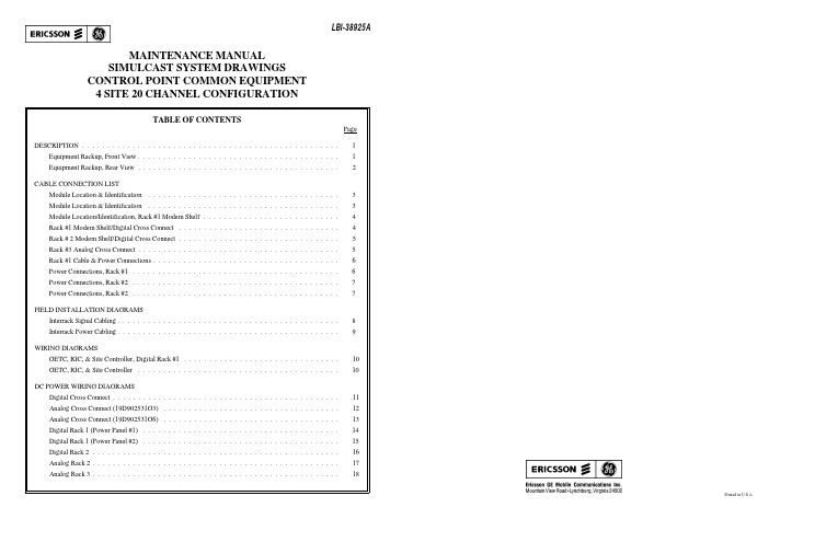
LBI-38925APrinted in U.S.A.MAINTENANCE MANUAL SIMULCAST SYSTEM DRAWINGS CONTROL POINT COMMON EQUIPMENT 4 SITE 20 CHANNEL CONFIGURATIONDESCRIPTIONThis manual contains the equipment configuration drawings, cable inter and intrarack wiring diagrams required for installation and maintenance of a Simulcast System with up to 4 sites and 20 chanels.It also contains the cable connection lists that provide detailed rack interconnect cabling information to support the wiring diagrams referenced above. They also identify the location of the equipment modules in each shelf. Being aware of the information contained on each of these drawings make servicing the simulcast system easier.The configuration drawings identify the shelves and the site/channel associations of each, where applicable, of the various shelves located in the Digital, Analog, GETC, and Test Equipment racks used in the Simulcast Communications System. The configuration drawings also show the rear view of the racks to identify the interconnecting jack and cable terminations for each shelf on the digital and analog equipment racks.Field installation drawings show the cabinet interconnect cabling between the simulcast digital, analog and test equipment racks and also between digital rack 1 of the simulcast equipment and the GETC, RIC, and Site Controller cabinets. Detailed cable termination points are given on cable connection list 344A4886 referenced on the field installation drawings.DC power wiring diagrams show the power distribution wiring from the power supplies through the power panel to the various shelves in each equipment rack. Cable connection list 344A4223 identifies the location of each module within the rack and details the interrack cabling connections.Digital cross connect diagrams define the cable connections between the digital cross connect panel and connector panels #1 and 2, digital delay shelf, analog processing shelf #2, and the universal sync shelf. The diagram traces the digital channel paths from the GETC/GETC interface module through the connector panel and digital cross connect panel to the digital delay shelf. It also shows the data and clock interconnections, for each site, through the modems and jackfields to the digital cross connect panel.Analog cross connect diagrams show the interconnections between the analog processing shelf #1, the connector panel, and the analog delay shelf that provide the voice channels for the simulcast system. It also shows the 150 baud interconnect with the digital cross connect and analog BSEL.Copyright © April 1993, Ericsson GE Mobile Communications Inc.CONTROL POINT COMMON EQUIPMENT 4 SITE 20 CHANNEL CONFIGURATIONEquipment Rackup, Front View(19D904160 Sh. 6, Rev. 4)LBI-38925LBI-389251CONTROL POINT COMMON EQUIPMENTLBI-38925LBI-389254 SITE 20 CHANNEL CONFIGURATIONEquipment Rackup, Rear View(19D904160 Sh. 7, Rev. 32CABLE CONNECTION LISTSHELF AND MODULE NUMBERSDIGITAL DELAY SHELF19D902531G21DIGITAL DELAY MODULE19D902524P1ANALOG DELAY SHELF19D902531G3 OR G6ANALOG DELAY MODULE19D902526P1ANALOG PROCESSING SHELF #119D902543G1COMPRESSOR MODULE19A149739P1AUDIO BRIDGE MODULE19D902458P1EQUALIZER MODULE19A149738P1UNIVERSAL SYNC SHELF19D902541G1ALARM MODULE19D902334P1DIGITAL SELECTOR (150BAUD/CLK)19D902519P12400 BAUD MODEM MODULE19D902521P1UNIVERSAL SYNC MODULE19D902517P1ANALOG PROCESSING SHELF #219D902544G1AUDIO BRIDGE MODULE19D902458P1MULTITONE I/F MODULE19D902515P1MODEM SHELF19D902542G1MODEM I/F MODULE (9600 BAUD)19D902442P1MODEM MODULE (9600 BAUD)19A705178P1DIGITAL DELAY SHELFDIGITAL DELAYSLOT 01DIGITAL DELAY MODULE SITE #01 CHANNELS 1-10SITE #02 CHANNELS 1-10 SLOT 02DIGITAL DELAY MODULE SITE #03 CHANNELS 1-10SITE #04 CHANNELS 1-10 SLOT 06DIGITAL DELAY MODULE SITE #01 CHANNELS 11-20SITE #02 CHANNELS 11-20 SLOT 07DIGITAL DELAY MODULE SITE #03 CHANNELS 11-20SITE #04 CHANNELS 11-204 SITE 20 CHANNEL CONFIGURATIONModule Location & Identification(344A4223 Sh. 1, Rev. 3)UNIVERSAL SYN SHELFSLOT 01ALARM MODULESLOT 02150 BAUD DATA SELECTOR MODULESLOT 03FSK MODEMSLOT 05UNIVERSAL SYN MODULECHANNELS 01-04SLOT 06UNIVERSAL SYN MODULECHANNELS 05-08SLOT 07UNIVERSAL SYN MODULECHANNELS 09-12SLOT 08UNIVERSAL SYN MODULECHANNELS 13-16SLOT 09UNIVERSAL SYN MODULECHANNELS 17-20SLOT 129.6 CLOCK SELECTOR MODULEANALOG PROCESSING SHELF #2SLOT 01150 BAUD BRIDGESLOT 02MULTITONE MODULE SITE 01-04MODEM SHELFSLOT 01MODEM INTERFACE MODULE SITE #XXSLOT 02MODEM MODULE CHANNEL 01/11SLOT 03MODEM INTERFACE MODULE SITE #XXSLOT 04MODEM MODULE CHANNEL 02/12SLOT 05MODEM INTERFACE MODULE SITE #XXSLOT 06MODEM MODULE CHANNEL 03/13SLOT 07MODEM INTERFACE MODULE SITE #XXSLOT 08MODEM MODULE CHANNEL 04/14SLOT 09MODEM INTERFACE MODULE SITE #XXSLOT 10MODEM MODULE CHANNEL 05/15SLOT 11MODEM INTERFACE MODULE SITE #XXSLOT 12MODEM MODULE CHANNEL 06/16SLOT 13MODEM INTERFACE MODULE SITE #XXSLOT 14MODEM MODULE CHANNEL 07/17SLOT 15MODEM INTERFACE MODULE SITE #XXSLOT 16MODEM MODULE CHANNEL 08/18SLOT 17MODEM INTERFACE MODULE SITE #XXSLOT 18MODEM MODULE CHANNEL 09/19SLOT 19MODEM INTERFACE MODULE SITE #XXSLOT 20MODEM MODULE CHANNEL 10/204 SITE 20 CHANNEL CONFIGURATIONModule Location & Identification(344A4223, Rev. 3)LBI-38925LBI-389253CABLE CONNECTION LISTANALOG DELAY SHELF, SITES 1-4ANALOG DELAYSLOT 01ANALOG DELAY MODULE SITE #01 CHANNELS 01-12SLOT 02ANALOG DELAY MODULE SITE #01 CHANNELS 13-20SLOT 03ANALOG DELAY MODULE SITE #02 CHANNELS 01-12SLOT 04ANALOG DELAY MODULE SITE #02 CHANNELS 13-20SLOT 05ANALOG DELAY MODULE SITE #03 CHANNELS 01-12SLOT 06ANALOG DELAY MODULE SITE #03 CHANNELS 13-20SLOT 07ANALOG DELAY MODULE SITE #04 CHANNELS 01-12SLOT 08ANALOG DELAY MODULE SITE #04 CHANNELS 13-20SLOT 09SLOT 10AUDIO PROCESSING SHELF #1SLOT #1COMPRESSORSLOT #2AUDIO BRIDGESLOT #3EQUALIZER SITE #1SLOT #4EQUALIZER SITE #2SLOT #5EQUALIZER SITE #3SLOT #6EQUALIZER SITE #4SLOT #7COMPRESSORSLOT #8AUDIO BRIDGESLOT #9EQUALIZER SITE #1SLOT #10EQUALIZER SITE #2SLOT #11EQUALIZER SITE #3SLOT #12EQUALIZER SITE #4RACK #1 19D904160P3FROM TO CABLES1DIGITAL CROSS CONNECT J57MODEM SHELF D100-A J0119D903985P14 S1DIGITAL CROSS CONNECT J87MODEM SHELF D100-A J0219D903985P16 S2DIGITAL CROSS CONNECT J58MODEM SHELF D101-A J0119D903985P14 S2DIGITAL CROSS CONNECT J88MODEM SHELF D101-A J0219D903985P14 S1MODEM SHELF D100-A J04JACKFIELD D602 P0119D903985P22 S1MODEM SHELF D100-A J06JACKFIELD D603 P0119D903985P22 S1MODEM SHELF D100-B J06JACKFIELD D603 P0219D903985P22 S2MODEM SHELF D101-A J04JACKFIELD D602 P0219D903985P22 S2MODEM SHELF D101-A J06JACKFIELD D604 P0119D903985P22 S2MODEM SHELF D101-B J06JACKFIELD D604 P0219D903985P22 4 SITE 20 CHANNEL CONFIGURATIONModule Location/Identification, Rack #1 Modem Shelf(344A4223, Rev. 3)S1MODEM SHELF D100-A J1A MODEM SHELF D100-B J119D903985P12 S1MODEM SHELF D100-A J2A MODEM SHELF D100-B J219D903985P12 S1MODEM SHELF D100-A J3A MODEM SHELF D100-B J319D903985P12 S1MODEM SHELF D100-A J4A MODEM SHELF D100-B J419D903985P12 S2MODEM SHELF D101-A J1A MODEM SHELF D101-B J119D903985P12 S2MODEM SHELF D101-A J2A MODEM SHELF D101-B J219D903985P12 S2MODEM SHELF D101-A J3A MODEM SHELF D101-B J319D903985P12 S2MODEM SHELF D101-A J4A MODEM SHELF D101-B J419D903985P12S1C01-10 DIGITAL CROSS CONNECT J27DIGITAL DELAY D300P0119D903985P16 S2C01-10 DIGITAL CROSS CONNECT J28DIGITAL DELAY D300P0219D903985P16 S3C01-10 DIGITAL CROSS CONNECT J29DIGITAL DELAY D300P0319D903985P16 S4C01-10 DIGITAL CROSS CONNECT J30DIGITAL DELAY D300P0419D903985P16S1C11-20 DIGITAL CROSS CONNECT J37DIGITAL DELAY D300P1119D903985P18 S2C11-20 DIGITAL CROSS CONNECT J38DIGITAL DELAY D300P1219D903985P18 S3C11-20 DIGITAL CROSS CONNECT J39DIGITAL DELAY D300P1319D903985P18 S4C11-20 DIGITAL CROSS CONNECT J40DIGITAL DELAY D300P1419D903985P18C01DIGITAL CROSS CONNECT J01CONNECTOR PANEL #01P0119D903985P24 C02DIGITAL CROSS CONNECT J02CONNECTOR PANEL #01P0219D903985P24 C03DIGITAL CROSS CONNECT J03CONNECTOR PANEL #01P0319D903985P24 C04DIGITAL CROSS CONNECT J04CONNECTOR PANEL #01P0419D903985P24 C05DIGITAL CROSS CONNECT J05CONNECTOR PANEL #01P0519D903985P24 C06DIGITAL CROSS CONNECT J06CONNECTOR PANEL #01P0619D903985P24 C07DIGITAL CROSS CONNECT J07CONNECTOR PANEL #01P0719D903985P24 C08DIGITAL CROSS CONNECT J08CONNECTOR PANEL #01P0819D903985P24 C09DIGITAL CROSS CONNECT J09CONNECTOR PANEL #01P0919D903985P24 C10DIGITAL CROSS CONNECT J10CONNECTOR PANEL #01P1019D903985P24 C11DIGITAL CROSS CONNECT J11CONNECTOR PANEL #01P1119D903985P24 C12DIGITAL CROSS CONNECT J12CONNECTOR PANEL #01P1219D903985P24 C13DIGITAL CROSS CONNECT J13CONNECTOR PANEL #01P1319D903985P24 C14DIGITAL CROSS CONNECT J14CONNECTOR PANEL #01P1419D903985P24 C15DIGITAL CROSS CONNECT J15CONNECTOR PANEL #01P1519D903985P24 C16DIGITAL CROSS CONNECT J16CONNECTOR PANEL #01P1619D903985P24 C17DIGITAL CROSS CONNECT J17CONNECTOR PANEL #01P1719D903985P24 C18DIGITAL CROSS CONNECT J18CONNECTOR PANEL #01P1819D903985P24 C19DIGITAL CROSS CONNECT J19CONNECTOR PANEL #01P1919D903985P24 C20DIGITAL CROSS CONNECT J20CONNECTOR PANEL #01P2019D903985P24 4 SITE 20 CHANNEL CONFIGURATIONRack #1 Modem Shelf/Digital Cross Connect(344A4223, Rev. 3)LBI-38925LBI-38925 4CABLE CONNECTION LISTC1-4DIGITAL CROSS CONNECT J71UNIV. SYNC SHF D800P0519D903985P16C5-8DIGITAL CROSS CONNECT J72UNIV. SYNC SHF D800P0619D903985P16C9-12DIGITAL CROSS CONNECT J73UNIV. SYNC SHF D800P0719D903985P16C13-16DIGITAL CROSS CONNECT J74UNIV. SYNC SHF D800P0819D903985P16C17-2O DIGITAL CROSS CONNECT J75UNIV. SYNC SHF D800P0919D903985P16A DIGITAL CROSS CONNECT J26JACKFIELD D600P0119D903985P24A ANALOG PROC SHF D700 J02JACKFIELD D600P0219D903985P52A DIGITAL CROSS CONNECT J79ANALOG PROC SHF D700J0119D903985P36A DIGITAL CROSS CONNECT J82ANALOG PROC SHF D700J0319D903985P36A DIGITAL CROSS CONNECT J67UNIV. SYNC SHF D800P0119D903985P16A DIGITAL CROSS CONNECT J68UNIV. SYNC SHF D800P0219D903985P16A DIGITAL CROSS CONNECT J69UNIV. SYNC SHF D800P0319D903985P16A DIGITAL CROSS CONNECT J70UNIV. SYNC SHF D800P0419D903985P16A DIGITAL CROSS CONNECT J78UNIV. SYNC SHF D800P1219D903985P16A DIGITAL CROSS CONNECT J98PANEL #3 A1P0119D903985P14A PANEL #3 A1P02JACKFIELD D601J0119D903985P36A DIGITAL CROSS CONNECT J99PANEL #3 A2P0119D903985P14A PANEL #3 A2P02JACKFIELD D601P0119D903985P26A DIGITAL CROSS CONNECT J85PANEL #3 A3P0119D903985P14A PANEL #3 A3P02JACKFIELD D601J0219D903985P36A DIGITAL CROSS CONNECT J86PANEL #3 A4P0119D903985P14A PANEL #3 A4P02JACKFIELD D601P0219D903985P26D102A DIGITAL CROSS CONNECT J59CONNECTOR PANEL #02P0119D903985P24D102B DIGITAL CROSS CONNECT J89CONNECTOR PANEL #02P0219D903985P24D103A DIGITAL CROSS CONNECT J60CONNECTOR PANEL #02P0319D903985P24D103B DIGITAL CROSS CONNECT J90CONNECTOR PANEL #02P0419D903985P24DCC DIGITAL CROSS CONNECT J80CONNECTOR PANEL #02P0519D903985P24DCC DIGITAL CROSS CONNECT J81CONNECTOR PANEL #02P0619D903985P24DCC DIGITAL CROSS CONNECT J83CONNECTOR PANEL #02P0719D903985P24DCC DIGITAL CROSS CONNECT J84CONNECTOR PANEL #02P0819D903985P24RACK #219D904160P5S3CONNECTOR PANEL #01 P01MODEM SHELF D102-A J0119D903985P28S3CONNECTOR PANEL #01 P02MODEM SHELF D102-A J0219D903985P28S4CONNECTOR PANEL #01 P03MODEM SHELF D103-A J0119D903985P28S4CONNECTOR PANEL #01 P04MODEM SHELF D103-A J0219D903985P284 SITE 20 CHANNEL CONFIGURATIONRack # 2 Modem Shelf/Digital Cross Connect(344A4223, Rev. 3)S3MODEM SHELF D102-A J04JACKFIELD D605P0119D903985P22S3MODEM SHELF D102-A J06JACKFIELD D606P0119D903985P22S3MODEM SHELF D102-B J06JACKFIELD D606P0219D903985P22S4MODEM SHELF D103-A J04JACKFIELD D605P0219D903985P22S4MODEM SHELF D103-A J06JACKFIELD D608P0119D903985P22S4MODEM SHELF D103-B J06JACKFIELD D608P0219D903985P22S3MODEM SHELF D102-A J1A MODEM SHELF D102-B J119D903985P12S3MODEM SHELF D102-A J2A MODEM SHELF D102-B J219D903985P12S3MODEM SHELF D102-A J3A MODEM SHELF D102-B J319D903985P12S3MODEM SHELF D102-A J4A MODEM SHELF D102-B J419D903985P12S4MODEM SHELF D103-A J1A MODEM SHELF D103-B J119D903985P12S4MODEM SHELF D103-A J2A MODEM SHELF D103-B J219D903985P12S4MODEM SHELF D103-A J3A MODEM SHELF D103-B J319D903985P12S4MODEM SHELF D103-A J4A MODEM SHELF D103-B J419D903985P12C11-12CONNECTOR PANEL 01P05ANALOG PROC SHF A406J0319D903985P48C13-14CONNECTOR PANEL 01P06ANALOG PROC SHF A407J0319D903985P48C15-16CONNECTOR PANEL 01P07ANALOG PROC SHF A408J0319D903985P48C17-18CONNECTOR PANEL 01P08ANALOG PROC SHF A409J0319D903985P48C19-20CONNECTOR PANEL 01P09ANALOG PROC SHF A410J0319D903985P46C10-11CONNECTOR PANEL 01P10ANALOG PROC SHF A406J0119D903985P28C13-14ANALOG PROC SHF A406J02ANALOG PROC SHF A407J0119D903985P12C15-16ANALOG PROC SHF A407J02ANALOG PROC SHF A408J0119D903985P12C17-18ANALOG PROC SHF A408J02ANALOG PROC SHF A409J0119D903985P12C19-20ANALOG PROC SHF A409J02ANALOG PROC SHF A410J0119D903985P12RACK #3 19D904160P4A JACKFIELD A600P01ANALOG PROC SHF A401J0119D903985P22C01-02ANALOG CROSS CONNECT J01ANALOG PROC SHF A401J0319D903985P64C03-04ANALOG CROSS CONNECT J02ANALOG PROC SHF A402J0319D903985P64C05-06ANALOG CROSS CONNECT J03ANALOG PROC SHF A403J0319D903985P62C07-08ANALOG CROSS CONNECT J04ANALOG PROC SHF A404J0319D903985P62C09-10ANALOG CROSS CONNECT J05ANALOG PROC SHF A405J0319D903985P62S1 C1-20ANALOG CROSS CONNECT J26ANALOG DELAY SHF A200 P0119D903985P18S2 C1-20ANALOG CROSS CONNECT J27ANALOG DELAY SHF A200 P0219D903985P18S3 C1-20ANALOG CROSS CONNECT J28ANALOG DELAY SHF A200 P0319D903985P18S4 C1-20ANALOG CROSS CONNECT J29ANALOG DELAY SHF A200 P0419D903985P18S 1-2-3ANALOG CROSS CONNECT J31ANALOG DELAY SHF A200 P1119D903985P18S 4ANALOG CROSS CONNECT J32ANALOG DELAY SHF A200 P1219D903985P184 SITE 20 CHANNEL CONFIGURATIONRack #3 Analog Cross Connect(344A4223, Rev. 3)LBI-38925LBI-389255CABLE CONNECTION LISTS1 C1-20ANALOG DELAY SHF A200P06JACKFIELD A600P0219D903985P24 S2 C1-20ANALOG DELAY SHF A200P07JACKFIELD A601P0119D903985P24 S3 C1-20ANALOG DELAY SHF A200P08JACKFIELD A601P0219D903985P24 S4 C1-20ANALOG DELAY SHF A200P09JACKFIELD A602P0119D903985P24C 3-4ANALOG PROC SHF A401J02ANALOG PROC SHF A402J0119D903985P12 C 5-6ANALOG PROC SHF A402J02ANALOG PROC SHF A403J0119D903985P12 C 7-8ANALOG PROC SHF A403J02ANALOG PROC SHF A404J0119D903985P12 C 9-10ANALOG PROC SHF A404J02ANALOG PROC SHF A405J0119D903985P12A406ANALOG CROSS CONNECT J06CONNECTOR PANEL 01P0119D903985P44 A407ANALOG CROSS CONNECT J07CONNECTOR PANEL 01P0219D903985P44 A408ANALOG CROSS CONNECT J08CONNECTOR PANEL 01P0319D903985P44 A409ANALOG CROSS CONNECT J09CONNECTOR PANEL 01P0419D903985P44 A410ANALOG CROSS CONNECT J10CONNECTOR PANEL 01P0519D903985P44 ACC ANALOG PROC SHF A405J02CONNECTOR PANEL 01P0619D903985P22 ACC ANALOG CROSS CONNECT J33CONNECTOR PANEL 01P0719D903985P24 ACC ANALOG CROSS CONNECT J34CONNECTOR PANEL 01P0819D903985P24ANALOG DELAY SHELF 19D902531G3150 DATA ANALOG DELAY SHF A200P13 PANEL #3 B1J0119D903985P14 150 DATA ANALOG DELAY SHF A200P14 PANEL #3 B1J0219D903985P14 150 DATA PANEL #3 B1J05JACKFIELD A602P0219D903985P52 ANALOG DELAY SHELF 19D902531G6150 DATA ANALOG DELAY SHF A200P13 JACKFIELD A602P0219D903985P24POWER CONNECTIONSRACK #1PP1POWER PANEL #01 P05DIGITAL DELAY SHELF TB119D903880P721 PP1POWER PANEL #01 P07UNIVERSAL SYN SHELF TB119D903880P784 PP1POWER PANEL #01 P08ANALOG PROC SHLF #2 P16/P1719D903880P733 PS1TB1-01YELLOW+5BUS+5PS1TB1-02YELLOW+5PS1TB1-03YELLOW+5PS1TB1-04YELLOW+5BUS+5PS1TB1-05YELLOW+5PS1TB1-06YELLOW+54 SITE 20 CHANNEL CONFIGURATIONRack #1 Cable & Power Connections(344A4223, Rev. 3)PS1TB1-07BLACK GND BUSGDPS1TB1-08BLACK GNDPS1TB1-09BLACK GNDPS1TB1-10BLACK GND BUSGDPS1TB1-11BLACK GNDPS1TB1-12BLACK GNDPS1TB1-13ORANGE+12BUS+12PS1TB1-14BLUE-12BUS-12PS1TB1-14BLUE-12BUS-12PS1TB1-15BLACK GND BUSGDPS1TB1-16BROWN+5 SENS BUS +5PS1TB1-17WHITE RTN SENS BUSGDPP2POWER PANEL #02 P01MODEM SHELF D100A TB119D903880P714 PP2POWER PANEL #02 P02MODEM SHELF D100B TB119D903880P714 PP2POWER PANEL #02 P03MODEM SHELF D101A TB119D903880P714 PP2POWER PANEL #02 P04MODEM SHELF D101B TB119D903880P714 PS2TB1-01YELLOW+5BUS+5PS2TB1-02YELLOW+5PS2TB1-03YELLOW+5PS2TB1-04YELLOW+5BUS+5PS2TB1-05YELLOW+5PS2TB1-06YELLOW+5PS2TB1-07BLACK GND BUSGDPS2TB1-08BLACK GNDPS2TB1-09BLACK GNDPS2TB1-10BLACK GND BUSGDPS2TB1-11BLACK GNDPS2TB1-12BLACK GNDPS2TB1-13ORANGE+12BUS+12PS2TB1-14BLUE-12BUS-12PS2TB1-14BLUE-12BUS-12PS2TB1-15BLACK GND BUSGDPS2TB1-16BROWN+5 SENS BUS+5PS2TB1-17WHITE RTN SENS BUSGD4 SITE 20 CHANNEL CONFIGURATIONPower Connections, Rack #1(344A4223, Rev. 3)LBI-38925LBI-38925 6CABLE CONNECTION LISTRACK #2PP1POWER PANEL #01 P01MODEM SHELF D102A TB119D903880P714PP1POWER PANEL #01 P02MODEM SHELF D102B TB119D903880P714PP1POWER PANEL #01 P03MODEM SHELF D103A TB119D903880P714PP1POWER PANEL #01 P04MODEM SHELF D103B TB119D903880P714PS2TB1-01YELLOW+5BUS+5PS2TB1-02YELLOW+5PS2TB1-03YELLOW+5PS2TB1-04YELLOW+5BUS+5PS2TB1-05YELLOW+5PS2TB1-06YELLOW+5PS2TB1-07BLACK GND BUSGDPS2TB1-08BLACK GNDPS2TB1-09BLACK GNDPS2TB1-10BLACK GND BUSGDPS2TB1-11BLACK GNDPS2TB1-12BLACK GNDPS2TB1-13ORANGE+12BUS+12PS2TB1-14BLUE-12BUS-12PS2TB1-14BLUE-12BUS-12PS2TB1-15BLACK GND BUSGDPS2TB1-16BROWN+5 SENS BUS+5PS2TB1-17WHITE RTN SENS BUSGDPP1POWER PANEL #02 P01ANALOG PROC SHF A406 TB119D903880P774PP1POWER PANEL #02 P02ANALOG PROC SHF A407 TB119D903880P774PP1POWER PANEL #02 P03ANALOG PROC SHF A408 TB119D903880P774PP1POWER PANEL #02 P04ANALOG PROC SHF A409 TB119D903880P774PP1POWER PANEL #02 P05ANALOG PROC SHF A410 TB119D903880P774RACK #3PS1POWER SUPPLY PS1 TB1-1/6POWER SUPPLY PS2 TB1-1/619D903880P810PS2POWER PANEL #01 P1319D903880P804P13-01 BLUE-12POWER SUPPLY PS2 TB1- #1P13-02 BLUE-12POWER SUPPLY PS2 TB1- #2P13-03 BLACK GND POWER SUPPLY PS2 TB1- #3P13-04 BLACK GND POWER SUPPLY PS2 TB1- #4P13-05 GREEN-24POWER SUPPLY PS2 TB1- #5P13-06 GREEN-24POWER SUPPLY PS2 TB1- #64 SITE 20 CHANNEL CONFIGURATIONPower Connections, Rack #2(344A4223, Rev. 3)PP1POWER PANEL #01 P01ANALOG PROC SHF A401 TB119D903880P774PP1POWER PANEL #01 P02ANALOG PROC SHF A402 TB119D903880P774PP1POWER PANEL #01 P03ANALOG PROC SHF A403 TB119D903880P774PP1POWER PANEL #01 P04ANALOG PROC SHF A404 TB119D903880P774PP1POWER PANEL #01 P05ANALOG PROC SHF A405 TB119D903880P7744 SITE 20 CHANNEL CONFIGURATIONPower Connections, Rack #2(344A4223, Rev. 3LBI-38925LBI-389257FIELD INSTALLATION DIAGRAMLBI-38925LBI-389254 SITE 20 CHANNEL CONFIGURATIONInterrack Signal Cabling(19C852394 Sh. 2 Rev. 0)8FIELD INSTALLATION DIAGRAMLBI-38925LBI-389254 SITE 20 CHANNEL CONFIGURATIONInterrack Power Cabling(19C852394 Sh. 1 Rev. 0)9CABLE CONNECTION LISTDIGITAL RACK #1FROM TO CABLERACK #1 CONNECTOR PANEL 01 P01GETC RACK #GETC CH 0119D903880P123A RACK #1 CONNECTOR PANEL 01 P02GETC RACK #GETC CH 0219D903880P123A RACK #1 CONNECTOR PANEL 01 P03GETC RACK #GETC CH 0319D903880P123A RACK #1 CONNECTOR PANEL 01 P04GETC RACK #GETC CH 0419D903880P123A RACK #1 CONNECTOR PANEL 01 P05GETC RACK #GETC CH 0519D903880P123A RACK #1 CONNECTOR PANEL 01 P06GETC RACK #GETC CH 0619D903880P123A RACK #1 CONNECTOR PANEL 01 P07GETC RACK #GETC CH 0719D903880P123A RACK #1 CONNECTOR PANEL 01 P08GETC RACK #GETC CH 0819D903880P123A RACK #1 CONNECTOR PANEL 01 P09GETC RACK #GETC CH 0919D903880P123A RACK #1 CONNECTOR PANEL 01 P10GETC RACK #GETC CH 1019D903880P123A RACK #1 CONNECTOR PANEL 01 P11GETC RACK #GETC CH 1119D903880P123A RACK #1 CONNECTOR PANEL 01 P12GETC RACK #GETC CH 1219D903880P123A RACK #1 CONNECTOR PANEL 01 P13GETC RACK #GETC CH 1319D903880P123A RACK #1 CONNECTOR PANEL 01 P14GETC RACK #GETC CH 1419D903880P123A RACK #1 CONNECTOR PANEL 01 P15GETC RACK #GETC CH 1519D903880P123A RACK #1 CONNECTOR PANEL 01 P16GETC RACK #GETC CH 1619D903880P123A RACK #1 CONNECTOR PANEL 01 P17GETC RACK #GETC CH 1719D903880P123A RACK #1 CONNECTOR PANEL 01 P18GETC RACK #GETC CH 1819D903880P123A RACK #1 CONNECTOR PANEL 01 P19GETC RACK #GETC CH 1919D903880P123A RACK #1 CONNECTOR PANEL 01 P20GETC RACK #GETC CH 2019D903880P123A RACK #1 CONNECTOR PANEL 02 P01RACK #2 CONNECTOR PANEL 01 P0119D903880P120J RACK #1 CONNECTOR PANEL 02 P02RACK #2 CONNECTOR PANEL 01 P0219D903880P120J RACK #1 CONNECTOR PANEL 02 P03RACK #2 CONNECTOR PANEL 01 P0319D903880P120J RACK #1 CONNECTOR PANEL 02 P04RACK #2 CONNECTOR PANEL 01 P0419D903880P120J RACK #1 CONNECTOR PANEL 02 P05RACK TEST CONNECTOR PANEL 01 P1219D903880P120B RACK #1 CONNECTOR PANEL 02 P06RACK TEST CONNECTOR PANEL 01 P1319D903880P120C RACK #1 CONNECTOR PANEL 02 P07RACK #3 CONNECTOR PANEL 01 P0719D903880P123D RACK #1 CONNECTOR PANEL 02 P08FIELD INSTAL DIGITAL ALARMSDIGITAL CROSS CONNECT P97GETC CAB. SYNC CTRL (SERIAL DATA J24)19D903880P25E 4 SITE 20 CHANNEL CONFIGURATIONGETC, RIC, & Site Controller, Digital Rack #1(344A4886, Rev. 0)RACK #3 CONNECTOR PANEL 01 P01RACK #2 CONNECTOR PANEL 01 P0519D903880P123F RACK #3 CONNECTOR PANEL 01 P02RACK #2 CONNECTOR PANEL 01 P0619D903880P123F RACK #3 CONNECTOR PANEL 01 P03RACK #2 CONNECTOR PANEL 01 P0719D903880P123F RACK #3 CONNECTOR PANEL 01 P04RACK #2 CONNECTOR PANEL 01 P0819D903880P123F RACK #3 CONNECTOR PANEL 01 P05RACK #2 CONNECTOR PANEL 01 P0919D903880P123F RACK #3 CONNECTOR PANEL 01 P06RACK #2 CONNECTOR PANEL 01 P1019D903880P120H RACK #3 CONNECTOR PANEL 01 P08FIELD INSTAL ANALOG BSELPP1RACK #1 POWER PANEL #01 J09TEST RACK ALARM SHELF J0119D903880P740AAHYBRID SHELD J16HYBRID SHELD J17PP1RACK #1 POWER PANEL #01 J12RACK #3 POWER PANEL #01(-24) J1419D903880P750BBPP1RACK #3 POWER PANEL #01 J15RACK #2 POWER PANEL #02 J1319D903880P790EEPP1RACK #1 POWER PANEL #01 J06RACK #3 ANALOG DELAY SHELF TB119D903880P729CCPP1RACK #3 POWER PANEL #01 J16TEST PACK ALIGNMENT REC TB119D903880P900DD SITE CONTROLLER TO THE GETC RACK AND TO THE RIC RACKGETC RACKCABLE LENGTH PANEL 1 MODULE 1 GETC DATA 1-12J14 SITE CNTL PANEL 1 MODULE 4 J14 Z19D903880P12115’PANEL 1 MODULE 2 VOTER DATA 1-12 J14 DIGITAL VOTER I/F CROSS CONN J61 Y19D903880P12115’PANEL 1 MODULE 3 NOT USED IN SIMULCAST SYSTEMPANEL 1 MODULE 4 SERIAL J21 SITE CNTL PANEL 1 MODULE 6 J07 W19D903880P162 10’PANEL 1 MODULE 5 GETC RESETPANEL 1 MODULE 6 NOT USED IN SIMULCAST SYSTEMPANEL 2 MODULE 1 GETC DATA 13-24 J14 SITE CNTL PANEL 1 MODULE 5 J14 D19D903880P12115’RIC RACKPANEL 1 MODULE 3 RIC AUDIO (LIX)1-12 J14 SITE CNTL PANEL 1 MODULE 2 J14 R 19D903880P12115’PANEL 1 MODULE 4 RIC AUDIO (LIX)13-24 J14 SITE CNTL PANEL 1 MODULE 3 J14 S 19D903880P12115’PANEL 1 MODULE 5 SERIAL LINK J21 SITE CNTL PANEL 1 MODULE 6 J04 T 19D903880P16210’PANEL 1 MODULE 6SITE CONTROLLERPANEL 2 MODULE 2 EXTERNAL PHONE LINE 1-12 CONNECTION (TO PLA MODULE)PANEL 2 MODULE 3 EXTERNAL PHONE LINE 13-24 CONNECTION (TO PLA MODULE)4 SITE 20 CHANNEL CONFIGURATIONGETC, RIC, & Site Controller(344A4886, Rev. 0)LBI-38925LBI-38925WIRING LISTLBI-38925LBI-389254 SITE 20 CHANNEL CONFIGURATIONDigital Cross Connect(19C852271 Rev. 3)WIRING LISTLBI-38925LBI-389254 SITE 20 CHANNEL CONFIGURATIONAnalog Cross Connect (19D902531G3)(19C852272 Sh.1, Rev. 3)WIRING LISTLBI-38925LBI-389254 SITE 20 CHANNEL CONFIGURATIONAnalog Cross Connect (19D902531G6)(19C852272 Sh.2, Rev. 0)WIRING LISTLBI-38925LBI-389254 SITE 20 CHANNEL CONFIGURATIONDigital Rack 1 (Power Panel #1)(19C852414 Sh.1, Rev. 0)WIRING LISTLBI-38925LBI-389254 SITE 20 CHANNEL CONFIGURATIONDigital Rack 1 (Power Panel #2)(19C852414 Sh.2, Rev. 0)WIRING LISTLBI-38925LBI-389254 SITE 20 CHANNEL CONFIGURATIONDigital Rack 2(19C852414 Sh.3, Rev. 0)WIRING LISTLBI-38925LBI-389254 SITE 20 CHANNEL CONFIGURATIONAnalog Rack 2(19C852414 Sh.4, Rev. 0)WIRING LISTLBI-38925LBI-389254 SITE 20 CHANNEL CONFIGURATIONAnalog Rack 3(19C852414 Sh.5, Rev. 0)LBI-38925LBI-38925This page intentionally left blank。
iCORE Kiosk System 操作手册说明书
Embedded Compact PC .............................................. 12
Overview of Compact PC...........................................................12 Technical Data ...........................................................................14
Symbols used in this guide ..........................................................2 Important Safety Precautions.......................................................3
Therefore, you will find the CE mark on the device or packaging.
BSMI
The product is tested and complied with the requirement of the BSMI (Bureau of Standards, Metrology and Inspection, Ministry of Economic Affairs) directive CNS13438 with regard to “Electromagnetic compatibility” and CNS14336 for product safety.
●
Paragraphs following this symbol are actions to be performed in the
R449说明书

VOLTAGE REGULATOR
R 449
Installation and maintenance
LEROY-SOMER
INSTALLATION AND MAINTENANCE
VOLTAGE REGULATOR
R 449
Réf. 3219 GB - 4.33 - Typical diagrams .............................................................................................................................. 11 3.1 - AREP 1F LV excitation .......................................................................................................... 11 3.2 - AREP 1F MV excitation ......................................................................................................... 12 3.3 - AREP 3F LV excitation .......................................................................................................... 13 3.4 - AREP 3F MV excitation ......................................................................................................... 14 3.5 - 1F LV shunt + booster excitation ........................................................................................... 15 3.6 - 1F LV PMG excitation ............................................................................................................ 16
欧姆龙RFID
⑤本产品目录中述及的应用事例仅作为参考之用,实际使用时,应事前确认设备·装置的功能以及安全性等 之后,再进行使用。
Con la presente Omron dichiara che la RFID Sistema, V680-HS52Serie, V680-HS63 Serie, V680-HS65 Serie, V680-HA63B Serie sono conforme ai requisiti essenziali ed alle altre disposizioni pertinenti stabilite dalla direttiva 1999/5/CE.
6.价格
本手册中记载的标准价格仅供参考。此价格中不包含消费税。
7.适合范围
上述内容仅限日本国内地区的交易。 其他地区和海外的交易及使用注意事项请与当地销售网点的人员咨询。
RFID 系统
操作手册 3
前言
前言
安全注意事项
●安全使用警告标志 本说明书中的以下标志用于指出在确保安全使用 V680-HS63/-HS52/-HS65/-HA63B 和 V680-D2KF67/-D2KF67M/D2KF52M/-D8KF68/-D32KF68系统时,必须警惕的地方。这些注意事项中包含重要的安全信息,请务必阅读。
前言
放大器 V680-HA63B
天线
V680-HS52 V680-HS63 V680-HS65
英语 芬兰语 荷兰语 法语 瑞典语 丹麦语 德语 希腊语 意大利语 西班牙语 葡萄牙语 罗马尼亚语
3V技术通讯_cn(移除密码)

另外,如果 D111 参数针对外部定时和自定时方式之间 存在差异,则意味着外部编程器编程方式和自编程方式 允许的电压范围不同。自编程方式是指器件对自身存储 器进行编程操作,这是通过自举程序(参见 AN851)或 表写操作 (参见器件数据手册)来完成的。
需要注意的是,LVP (“低电压编程”)和在低 VDD 电 压下编程不是同一个概念。LVP 指的是 VPP 而非目标板 上的 VDD。LVP 是 PIC® 单片机(MCU)的功能之一, 允许用户在编程电压不超过 VDD 的条件下进行编程操 作。 LVP 并不代表器件可在 3V 条件下进行编程操作。
如果不是包括单片机在内的集成电路制造技术不断发展 进步,满足这一成本的挑战将是难以想象的。半导体公 司致力于提供具有最佳性价比的解决方案,同时实现更 低的系统成本和更多的集成功能。
单片机的成本和性能与制造工艺水平相关。当前最先进 的嵌入式闪存制造工艺达到 0.25µ,并正向 0.18µ 以及 更高的水平迈进。采用这一工艺等级制造的芯片内部的 逻辑电路难以工作在 5V 电压下。汽车引擎管理系统、 音响信号处理器、导航系统和视频娱乐设备中专用的高 性能单片机早已采用 3V 设计。为满足高速运算性能的 需求,采用小于 0.5µ 硅片制造工艺制造的器件最初运 用于汽车应用中。这些器件采用更低的供电电压。
推荐阅读
EMC 技术通讯
当使用我们的产品时,读者可从这些技术通讯中获得很多 新思路和设计技巧来改善产品的电磁兼容性能 (Electromagnetic Compatibility, EMC) 。读 者 可从 > Application Design Center > EMC Design 下载这些技术通讯的电子版本。
5V TTL
- 1、下载文档前请自行甄别文档内容的完整性,平台不提供额外的编辑、内容补充、找答案等附加服务。
- 2、"仅部分预览"的文档,不可在线预览部分如存在完整性等问题,可反馈申请退款(可完整预览的文档不适用该条件!)。
- 3、如文档侵犯您的权益,请联系客服反馈,我们会尽快为您处理(人工客服工作时间:9:00-18:30)。
电压调节器R 449 f版LEROY - SOMER安装和使用说明书3983 en - 05.2008 / c电压调节器R 449 f 版感谢您选用利莱森玛公司的产品本手册适用于您所购买的交流发电机A.V.R我们竭诚希望能引起我们竭诚希望能引起您您对本维护手册目录对本维护手册目录、、内容的关注内容的关注。
当您的A.V.R 在安装在安装、、运行和维修期间运行和维修期间,,应遵循应遵循下下述特定的特定的、、重要的指导重要的指导,,以确保发电机能够长期无故障运行以确保发电机能够长期无故障运行。
安全措施在首次使用发电机前,请反复细心阅读本手册中有关安装、维修的全部说明。
手册随机附送。
使用该机的一切必要操作和干涉,都应该由合格的技术人员来进行。
为了整个机器的寿命,本维修手册应当妥善保留,并给予编档保存。
我们的技术支持维护将十分乐于提供您所要求的任何附加信息。
手册中所说明的各道工序,都有推荐说明,或用种种符号来警示使用者,以避免出事故的危险。
理解和注意不同安全符号的含义对您来说是非常重要的。
该AVR 适用于标有CE的发电机注:利莱森玛公司对其任何时间产品的特性保留变更权,以便适应最新技术的发展。
因此,本文件中所含的信息将不做预先通知而作改变。
此为有可能导致机器或者周围设备的损害或毁坏的操作安全符号作安全符号。
此为有可能导致人身一般性危险的安全符号此为有可能导致人身一般性危险的安全符号。
此为有可能导致人身触电危险事故的安全符号此为有可能导致人身触电危险事故的安全符号。
版权 2005:LEROY-SOMER本文属于利莱森玛公司所有,未经我公司预先授权,不得以任何形式再版。
产品商标、型号及专利权已注册登记。
R 449 修订版f目录1.R 449介绍...................................................................................................................................................................4 1.1. 应用..................................................................................................................................................................................4 1.2. 描述. (4)1.2.1. 电源接线.................................................................................................................................................................4 1.3. 电气特性.. (6)1.3.1. 运行图.....................................................................................................................................................................6 1.3.2. 电压检测.................................................................................................................................................................7 1.3.3. 调压准确度.............................................................................................................................................................7 1.3.4. 电压调节.................................................................................................................................................................7 1.3.5. 电源.........................................................................................................................................................................7 1.3.6. 输出电压.................................................................................................................................................................7 1.3.7. 正交调差.................................................................................................................................................................7 1.3.8. 频率与电压特性(不带LAM )............................................................................................................................7 1.3.9. LAM (负载调节模块)特性.................................................................................................................................7 1.3.10. LAM 对柴油机的典型作用, 有/无LAM (只有U/F 功能)..............................................................................8 1.3.11. 渐变电压恢复功能.................................................................................................................................................8 1.3.12. 稳定性.....................................................................................................................................................................8 1.3.13. 极限励磁电流Iex 的设置......................................................................................................................................8 1.3.14. 保护.........................................................................................................................................................................9 1.3.15. 电压的建立.............................................................................................................................................................9 1.3.16. 使用功率.................................................................................................................................................................9 1.3.17. 灭磁.........................................................................................................................................................................9 1.4. 环境. (9)2.R726: 功率因数调节功率因数调节((2F )和电压匹配和电压匹配((3F ).........................................................................................................10 2.1. 运行图............................................................................................................................................................................10 2.2. 电位器. (11)3.典型的电气图.............................................................................................................................................................12 3.1. AREP 励磁系统1F LV(低压).........................................................................................................................................12 3.2. AREP 励磁系统1F MV(中压).........................................................................................................................................13 3.3. AREP 励磁系统3F LV(低压).........................................................................................................................................14 3.4. AREP 励磁系统3F MV(中压).........................................................................................................................................15 3.5. 自励励磁系统1F LV(低压)..........................................................................................................................................16 3.6. PMG 励磁系统1F LV(低压). (17)4.运行...........................................................................................................................................................................18 4.1. 单机调试........................................................................................................................................................................18 4.2. 并车运行调试(1F).....................................................................................................................................................18 4.3. 功率因素调节(2F)和电压匹配调节(3F)(见R726手册 ref.2440) (18)5.故障诊断 (20)5.1. 用他励检查绕组及旋转整流二极管.............................................................................................................................20 5.2. AVR 的静态检查..............................................................................................................................................................20 5.3. 故障处理表.. (21)5.3.1. 发电机之间的并车运行(1F )...........................................................................................................................21 5.3.2. 功率因数调节和电压匹配(2F 和3F ).............................................................................................................23 5.3.3. 用他励检查发电机...............................................................................................................................................23 5.4. 更换备用AVR (23)6.备用部件....................................................................................................................................................................24 6.1. 命名................................................................................................................................................................................24 6.2. 技术支持服务.. (24)AVR 上一切维护和操作上一切维护和操作,,都应该由在电子都应该由在电子、、机械工程领域运行机械工程领域运行、、维修维修、、维护等方面经过培训并被认可为合格的专业人员来进行维护等方面经过培训并被认可为合格的专业人员来进行。
