《高速信号处理FPGADSP设计》
基于FPGA+DSP的高速基带信号处理平台的设计
第 3期
ห้องสมุดไป่ตู้
2 0 1 4年 1月
科
学
技
术
与
工
程
Vo 1 . 1 4 N o . 3 J a n .2 0 1 4
1 6 7 1 —1 8 1 5 ( 2 0 1 4 ) 0 3 — 0 2 3 9 — 0 5
S c i e n c e T e c h n o l o g y a n d E n g i n e e r i n g
出 了一种改进高速基 带信号处理平 台的硬件 设计方 案。该 方案采 用 F P G A+D S P的处理 架构 , 依托 高性 能 的器 件和 高速接 口, 搭建 了一个高性 能的通用 基带信号处理平 台。该平 台直接实现对 中频数 字信号 的处 理 , 融合数 字上 下变频 与基 带算法于
一
的处理器 , 其优势在于 : ①充分结合了 D S P和 F P G A 各 自的优点 , 更好地发挥 了性能 ; ②结构灵活、 通用 性强 、 适用 于模块化设计 ; ③对不同结构的算法都有 较强 的适应能力 , 尤其适合实时信号处理; ④算法执 行效 率高 、 开 发周 期短 、 系 统易 于维 护和 扩展 等 。 结合各类无线通信 系统实际算 法需求 , 低层信 号预处理算法的数据 为符号级数据 , 虽然数据量大 但运 算结 构 相对 比较 简单 , 适 于用 F P G A 进 行 硬 件 实现。高层处理算法的数据 为比特型数据 , 其特点
一
是数据量较少 , 但算法的控制结构复杂 , 适于用 D S P 来 实 现 。F P G A 具 有 明 显 的 并 行 处 理 优 势 和 灵 活 性, D S P运算 速度 快 、 寻址 方 式 灵 活 , 二 者 均 能 满 足 处 理 复 杂算 法 的要 求 , 这样以 F P G A +D S P的架 构 为核 心 , 借 助 于高性 能 的器件 和高 速接 口 , 设计 了一 个 高性 能 信 号 处 理 硬 件 平 台 J 。该 平 台具 有 灵 活 的处理 结构 , 对 不 同结 构 的算 法都 有 较 强 的适 应 能 力, 尤其适合实时信号的处理。
基于DSP_FPGA的高速数字信号处理平台

术,该平台还具有一定的开放性和可
示意图与图2相似,只是核电压不同。
程序与数据存储器 F L A S H 采用 扩展性,可以很好地满足设计的完善、
由超大规模FPGA芯片和高速的DSP芯 Intel公司的E28F320,其存储容量为 功能的扩充及程序的更改。
片组成系统的核心,是为了发挥两者 32Mbit。由 DSP 的供电芯片TPS70348
图2 DSP芯片的供电示意图
表 1 FPGA 芯片与 DSP 芯片的比较
F P G A 芯片
编程方式
V H D L 、A H D L 语言及图形编程等,
实现容易
资源重复利用性
通过外部处理器动态配置
硬件资源结构
可实现并行的乘法器/加法器操作
处理速度
并行运算速度快,只受硬件结构限制
适合的信号处理运算 高速并行处理
的优势。FPGA 芯片与 DSP 芯片相比, 为其一起供电,TPS70348芯片的复位
系统的软件设计流程
由于其结构上的优势,FPGA芯片更适 信号 /RESET为 FLASH 和 DSP的共同复
本文设计的平台通过动态配置可
w w w . e e p w . c o m . c n 电子产品世界 2004.10 /下半月 91
式中:SNR为输出信号的信噪比; B 为比特分辨数,即A/D 的转换位数; 为采样速率;输入模拟信号的最高频
理技术已在通信、信息、电子、自动控
总体硬件框架
制、航天及军事等领域中得到广泛应
图1为本文要介绍
用。
的高速数字信号处理平
以现代通信理论为基础,以数字 台的硬件框图,主要包
信号处理为核心的软件无线电技术是 括五个功能块:高速A/
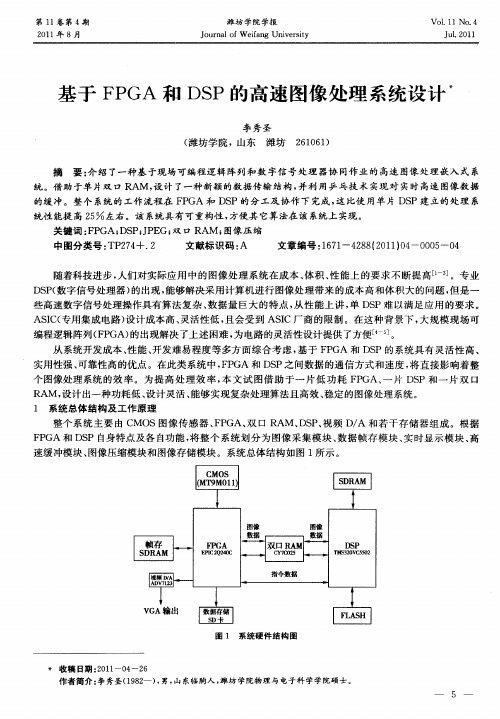
基于FPGA和DSP的高速图像处理系统设计
的缓 冲 。整 个 系统的 工作 流 程 在 F GA 和 D P的分 工 及协 作 下 完成 , 比使 用单 片 DS P S 这 P建 立 的处 理 系
统性 能提 高 2 左右 。该 系统 具 有可重 构性 , 5 方便 其 它算 法在该 系统上 实现 。
关键 词 : P F GA; S J E 双 口 RAM ; D P;P G; 图像 压 缩
第 1 卷 第 4期 1
21 0 1年 8月
潍 坊 学 院 学报
J u n l fW efn ie st o r a ia g Unv r i o y
V0 . 1N0 4 11 .
J 12 1 u. 0 1
基 于 F GA 和 DS P P的 高 速 图 像 处 理 系 统设 计
确 的配置之后 , 就可 以输 出 1 的图像数据 和一些 同步信 号 。在本系统 中采用 I O位 z C实现 传感 器配 置 ,P F— G 管脚通 过模拟 IC时序 , A 。 完成 对 C MOS 感器 的初始 化配置 , 中要 配置 的寄存 器如表 1 传 其 所示 。
表 1 MT M0 9 1寄存 器 设 置
编程逻 辑 阵列 ( P F GA) 出现解 决 了上 述 困难 , 电路 的灵活 性设 计提 供 了方便 [ 。 的 为 4 ]
从 系 统开发 成本 、 能 、 性 开发难 易程 度等 多方 面综 合考 虑 , 基于 F G 和 D P的系 统具 有 灵 活性 高 、 P A S 实用性 强 、 可靠性 高 的优 点 。在此类 系 统 中 ,P F GA和 DS P之 间 数据 的通 信 方式 和速 度 , 直 接影 响着 整 将 个 图像 处理 系统 的效 率 。为 提 高 处 理 效 率 , 文 试 图 借 助 于 一 片 低 功耗 F GA、 片 D P和 一 片 双 口 本 P 一 S
基于DSP+FPGA的高速数字信号处理平台的电源设计
现 具有 通 用 性 、 可扩 充性 的硬 件 平 台 , 对 电 源设 计 中的 多项 关键 参 数 进 行 分析 与 阐述 。 并 关键 词 : 场 可 编程 门阵 列 ; 字 信号 处 理 ; 现 数 数模 ; 源 管理 监控 电 中 图分 类 号 : 9 17 TN 1 .2 文献 标 识 码 : B 文 章编 号 :0 4 7X(O7 O —04— 3 10 —33 2O )6 4 0
A ta t A e a pr a h o o rd sgn f ih s e d diia i n lp o e sn af r sde eo d, ih mail m pe e - bsr c : n w p o c fp we e i orhg p e gt lsg a r c s ig plto m i v lpe whc ny i lm n
( . no mai n n ie r g C l g , hn ie s yo e s i cs W u n 4 0 7 , i 1 Ifr t n a d E gn ei o l e C iaUnv ri fG o c n e , h ,3 0 4 Chn o n e t e a 2 Ch a Unv ri fG o c n e . u n 4 0 7 , hm ) . i ies yo e s i c s W h , 3 0 4 C n t e i
t h i h s e ii l in l r e sn y me n f h o i ai no S n P d e t ehg p e d gt g a p o s i b a so ec mb n t fD P a d F GA c n lg . v n e hp u h a GA, d as c g t o t h o o y Ad a c c i ss c s e d FP
基于FPGA+DSP的高速视频实时处理系统设计
1310 引言随着经济的快速发展,各个领域对高速视频图像实时处理的速度与精度提出了更高的要求,譬如:机器人导航领域、现场监控领域、安防领域等。
在此背景下,高速视频图像实时处理技术得到了长足的发展[1]。
20世纪70年代,人们开始利用高速摄像机来记录运动的物体,但当时高速摄像机是以胶片的形式作为记录介质,无法实现数据的实时处理[2]。
现如今,高速工业相机的采样频率高达1000FPS (Frame Per Second)[3],由于高速视频图像实时处理系统具有数据量大,数据相关性高,而且对图像的帧、场时间具有严格的限制,因此,高速视频图像实时处理领域对中央处理芯片、外部存储芯片的工作速率以及核心算法的运算复杂度等都提出了极大的挑战[4]。
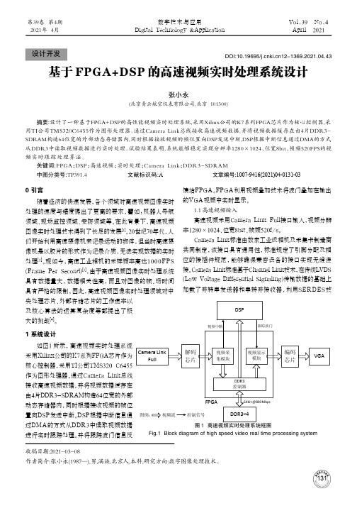
1 系统设计如图1所示,高速视频实时处理系统采用Xilinx公司的K7系列FPGA芯片作为核心控制器,采用TI公司TMS320 C6455作为图形处理器。
通过Camera Link总线接收高速视频数据,并将视频数据缓存在由4片DDR3-SDRAM构造64位宽的外部动态存储器内,同时根据接收视频的帧位置向DSP发送中断。
DSP根据中断信息通过DMA的方式从DDR3中读取视频数据进行实时跟踪处理。
并将跟踪波门信息反馈给FPGA。
FPGA利用视频叠加技术将波门叠加在输出的VGA视频中实时显示。
1.1 高速视频输入高速视频采用Camera Link Full接口输入,视频分辨率1280×1024、位宽8bit、帧频520f/s。
Camera Link标准由数家工业级相机及采集卡制造商共同制定,该接口具有通用性,标准规定了引脚分配及相应的接插件规范,能够确保兼容设备的接口实现无缝连接。
Camera Link标准基于Channel Link技术,在传统LVDS (Low Voltage Differential Signaling)传输数据的基础上加载了并转串发送器和串转并接收器,利用SER DES技收稿日期:2021-03-08作者简介:张小永(1987—),男,满族,北京人,本科,研究方向:数字图像处理技术。
FPGA与DSP的高速通信接口设计与实现

2.1链路口通信协议分析 Tsl01的链路口共有11根引脚,通过8根数据线
44
欢迎网上投稿www.aetnet.cn www.aetnet.com.cn
万方数据
《电子技术应用》2007年第4期
集成嘲瞳翔AppIicalIonof Integrated c㈣s
(kDAT[7..0],这里x可以是0、1、2或3,代表TSl01或 .Is201的0号一3号链路口中的一个,以下同)进行数据
知数据块传输的结束,
当能确定DMA传输数
据个数时,可以将此引
脚悬空。
TS201链路口的收
发机制非常相似,本文
图3 FPGA接收‘rSl01数据时序图
仅给出发送数据时序图,如图5所
2.3基于FPGA的TS201链路口设计 图4给出了FPGA与TS20l进行链路口通信的设计
框图。由于TS201的握手信号较多,所以相对TSl01的 链路口设计容易些。本设计FPGA时钟50MHz,TSlol核 时钟500MHz,链路口时钟为DSP核时钟的4分频,采用 4bit方式,单向实际数据传输速率为125MBps。
1 TSl01和TS201的链路口分析与比较 TSl01和TS210都是高性能的浮点处理芯片,目前两
来越广泛。ADI公司的TigerSHARC系列DSP芯片浮点 处理性能优越,故基于这类DSP的DSP+FPGA处理系
者都广泛应用于复杂的信号处理领域。rIs201是继rI’S101 之后推出的新型芯片,核时钟最高可达600MHz,其各类
7IS201
4个完全双向的链路口 通过SoC BUS接到片内SoC接口,
映射到存储区 24根引脚
16根LVDS数据线 时钟双沿触发的lbit,4bitDDR数据
高速数字信号处理中的FPGA设计与实现

高速数字信号处理中的FPGA设计与实现概述:高速数字信号处理在现代通信系统、雷达、成像和音频处理等领域发挥着重要作用。
为了实现高性能、低延迟和低功耗的数字信号处理,采用现场可编程门阵列(FPGA)来设计和实现算法成为一种主流选择。
本文将讨论高速数字信号处理中的FPGA设计与实现,介绍FPGA的基本原理和优点,并探讨在设计和优化数字信号处理算法时使用FPGA 的方法。
一、FPGA基本原理和优点FPGA是一种可重构硬件,通过编程方式实现逻辑功能的配置。
与传统的专用集成电路(ASIC)相比,FPGA具有以下优点:1. 灵活性:FPGA可以在设计完成后根据需要进行重新编程。
这使得它们适用于快速原型开发和快速迭代,同时提供了更高的设计灵活性。
2. 可定制性:FPGA可以按照用户需求进行定制和配置。
不同的算法和应用可以被实现和运行在同一片FPGA上,提供了更大的灵活性和可扩展性。
3. 并行处理能力:FPGA具有大量的逻辑单元和片上存储器,可以支持高度并行的数据处理。
这使得FPGA在高速数字信号处理中具有较高的性能和吞吐量。
4. 低功耗:相比ASIC,FPGA的功耗更低。
这在对于需要长时间运行的应用中尤为重要,如无线通信系统和数据中心。
二、高速数字信号处理中的FPGA设计和实现流程高速数字信号处理中的FPGA设计和实现可分为以下几个步骤:1. 确定需求:首先,需要明确高速数字信号处理的具体需求和目标。
这包括处理的信号类型、采样率、处理算法等。
2. 算法设计:接下来,根据需求设计和优化数字信号处理算法。
在这个步骤中,需要考虑算法的复杂度、延迟和资源需求。
3. FPGA架构设计:在此步骤中,根据算法的特点和需求,选择适合的FPGA架构。
需要考虑FPGA的逻辑单元、片上存储器和通信接口等特性。
4. 代码编写和验证:将算法转化为硬件描述语言(HDL)编写相应的代码。
使用FPGA开发板进行验证和测试,确保设计的正确性和性能。
基于FPGA的高速数字信号处理系统设计与实现
基于FPGA的高速数字信号处理系统设计与实现随着时代的进步和科技的发展,数字信号处理(Digital Signal Processing,简称DSP)在各个领域中扮演着重要角色。
而FPGA (Field Programmable Gate Array)作为一种强大的可编程逻辑器件,已经被广泛应用于高速信号处理系统中。
本文将探讨基于FPGA的高速数字信号处理系统的设计与实现。
1. 引言高速数字信号处理系统在实时性和处理速度方面要求较高。
传统的通用处理器往往无法满足这些需求,而FPGA的并行处理能力和灵活性使其成为处理高速数字信号的理想选择。
本文将着重讨论FPGA系统的设计和实现。
2. FPGA基础知识2.1 FPGA原理FPGA是一种可编程逻辑器件,由大量的可编程逻辑单元和存储单元构成。
通过编程可以实现逻辑门、存储器和各种电路。
FPGA的可重构性使得其适用于不同的应用领域。
2.2 FPGA架构常见的FPGA架构包括查找表(Look-up Table,简称LUT)、寄存器和可编程互连网络。
LUT提供逻辑功能,寄存器用于数据存储,而可编程互连网络则实现不同逻辑单元之间的连接。
3. 高速数字信号处理系统设计3.1 系统需求分析在设计高速数字信号处理系统之前,需要明确系统的需求和目标。
这可能包括处理速度、资源利用率、功耗等方面的要求。
3.2 系统架构设计基于FPGA的高速数字信号处理系统的架构设计是关键步骤之一。
需要根据系统需求和目标来选择合适的算法和硬件结构。
可以采用流水线结构、并行处理结构等以提高处理速度。
3.3 硬件设计硬件设计包括选择FPGA器件、选择合适的外设、设计适配电路等。
通过合理的硬件设计可以实现信号处理系统的高速和稳定运行。
4. 实现与验证4.1 FPGA编程使用HDL(Hardware Description Language)进行FPGA编程。
常用的HDL语言包括VHDL和Verilog。
结合FPGA与DSP实现对高速中频采样信号处理平台的设计详解
结合FPGA与DSP实现对高速中频采样信号处理平台的设计详解现代社会正向数字化、信息化方向高速发展,在这一过程中,往往需要高速信号的实时性数字化处理。
例如,随着科技的进步,现代雷达等应用信号的数字化处理上有了长足的发展,但也带来了新的问题,这些应用的数字信号处理具有海量运行需求的应用背景,如巡航导弹末制导雷达地形匹配、合成孔径雷达的成像处理、相控阵雷达的时空二维滤波处理等领域。
目前,单片DSP难以胜任许多信号处理系统的要求。
而常见的解决方案也是高速A/D采样与信号处理功能是在多块不同的板卡上实现,这给实际应用带来很多不便。
鉴于上述现有技术所存在的问题,本设计平台的目的是:
(1)实现高速中频信号(如雷达信号)的数字化处理并进行实时传输数据或进行数据的实时计算,并能通过输出电路进行结果显示;
(2)自定义控制总线可以实现对高速中频信号处理板进行灵活控制,具有较强的可配置性和丰富的灵活性;
(3)高速A/D采样与D/A回放及数据处理单元集成在一块板上,在集成度高的同时也降低了高速信号在传输过程中出现差错的概率。
1 平台设计方案高速中频采样信号处理平台由主控制电路、高速A/D与D/A电路、信号处理单元电路、光纤通道电路、时钟管理电路、存储单元和外部接口电路组成,其总体框图如图1所示。
在实际应用过程中,四路A/D通道可以接收不同的信号源的信号,D/A通路可以对外进行数据显示等多种功能,时钟管理电路管理内外时钟的使用及对板上系统供给工作时钟,两路光纤通道可以与其他高速设备相连接,自定义总线可以与CPU或主控制器相连接对平台进行有效灵活的控制。
1.1 高速A/D与D/A设计
四路高速A/D采样通道采用两片NS公司的ADC081000实现,每片有两个A/D通道,。
新一代DSP+FPGA高速数字信号处理方案
L … … 一 。
On l i n e S em i n ar Hi gh l i gh t s
占 用 一 定 的 时 钟 周 期 ,这 点 对 于 复 杂
的 算 法 是 可 以 接 受 的 ,但 是 ,如 果 数
据 量 大 ,任 务 重 复 的 时 候 , 会 造 成 很
合 众 科 技 有 限 公 司新 推 出 的 新 一 代 高
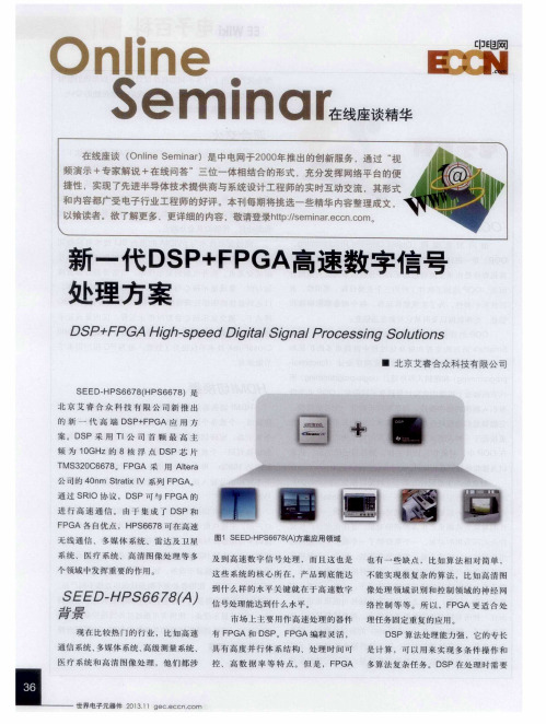
端F P GA + D S P应 用 方 案 。 该 平 台采 用 T l 公 司 主 频 最 高 可 达1 0 GH z的 多 核 心 定 浮 点 DS P芯 片
薹 I I 巷 I I l 薹 I I 彗 l 磊 l l 薹 叶 Q ∞ x
S E E D— HP S 6 6 7 8 ( A) 信号处理能达到什么水平 。
背景
现 在 比 较 热 门 的 行 业 , 比如 高 速 有 F P G A和 D S P。F P G A编程 灵活 ,
络控 制 等等 。所 以,F P GA 更 适 合 处
市场 上主要 用作高速 处理 的器 件 理 任 务 固 定 重 复 的 应 用 。
D S P 算 法 处 理 能 力 强 , 它 的 专 长
通信 系统 、 多媒体 系统 、 高级测量 系统 、 具 有 高 度 并 行 体 系 结 构 、处 理 时 间 可 是 计 算 ,可 以 用 来 实 现 多 条 件 操 作 和
S P 在 处 理 时 需 要 医 疗 系 统 和 高 清 图 像 处 理 , 他 们 都 涉 控 、高 数 据 率 等 特 点。但 是 ,F P GA 多算 法 复 杂任 务 。 D
图2 T MS 3 2 0 C 6 6 7 8 功 能框 图
T MS 3 2 0 C6 6 7 8 。此芯片凭 借多达 8 个核心的架构实现超高性能计算能力 。
基于DSP+FPGA的高速通用实时信号处理平台设计
c mp tri d n y DP o u e s o eb S,a da h a i e e u n ec n r l fe tr y tm sp r r d b PL n tt es met m ,s q e c o to n ies se i e{ me y C D o 0
第 3 2卷
第 2期
电气 电 子 教学 学 报 J 0URNAL 0F EE E
Vo J 2 NO 2 l3 .
Ap . 01 r2 0
21 0 0年 4月
基 于 DS +F G 的 高速通 用 实 时信 号处 理 平 台设计 P P A
曹政 才 , 应 涛 王光 国 赵 ,
h g — p e ft e d v c s a d t e c d — p i z t n,t e o h r l s i o r c n u t n a d b t e o t i h s e d o h e ie n h o e o tmia i o h t e i n l we o s mp i n e t r c s- e o e f c i e b sn P. fe t y u i g DS v
De i n o i h S e d Un v r a a — m e S g l s g fH g p e i e s lRe lTi i na
P o e sn lto m a e n DS r c si g P a f r B s d o P+ F PGA
i p e e t to f F T l o ih s i p ro me y FP m lm n a i n o F a g rt m s e f r d b GA , s e t u a a y i a d c mmu ia in wih p c r m n l ss n o nct t o
基于DSP和FPGA的通用数字信号处理系统设计

基于DSP和FPGA的通用数字信号处理系统设计一、本文概述随着数字信号处理技术的飞速发展,数字信号处理器(DSP)和现场可编程门阵列(FPGA)在通用数字信号处理系统设计中的应用越来越广泛。
本文旨在探讨基于DSP和FPGA的通用数字信号处理系统设计的相关理论、方法和技术,分析其在不同领域的应用及其优势,以期为未来数字信号处理技术的发展提供参考和借鉴。
本文首先介绍了数字信号处理的基本概念和发展历程,阐述了DSP和FPGA的基本原理和特点。
在此基础上,详细分析了基于DSP和FPGA的通用数字信号处理系统设计的核心技术和方法,包括系统架构设计、算法优化、硬件实现等方面。
结合实际应用案例,探讨了该系统在不同领域的应用及其性能表现。
通过本文的研究,我们可以深入了解基于DSP和FPGA的通用数字信号处理系统设计的关键技术,掌握其在实际应用中的优势和应用范围,为未来的数字信号处理技术的发展提供有益的参考和启示。
本文的研究也有助于推动数字信号处理技术在通信、音频处理、图像处理、生物医学工程等领域的广泛应用和发展。
二、DSP与FPGA基础知识数字信号处理(DSP)和现场可编程门阵列(FPGA)是现代电子系统设计中的两个关键元素。
DSP是一种专用的微处理器,用于执行复杂的数学运算,特别是快速傅里叶变换(FFT)等数字信号处理任务。
FPGA则是一种可编程的硬件逻辑设备,它允许设计师直接在硬件级别上实现复杂的数字逻辑。
DSP的设计主要围绕其高性能的数字处理能力,包括高效的算术和逻辑单元,以及优化的内存结构。
这使得DSP非常适合于处理需要高速运算和大量数据处理的应用,如音频和图像处理,无线通信,以及雷达和声纳信号处理等。
另一方面,FPGA的设计则基于其可编程性,允许设计师直接在硬件级别上实现复杂的数字逻辑。
FPGA内部包含大量的可编程逻辑块和可配置的内存,使得设计师可以根据需要自定义硬件功能。
这使得FPGA非常适合于需要高度定制化硬件的应用,如高性能计算,网络通信,以及复杂的控制系统等。
基于 FPGA 的高速 DSP 系统设计

基于 FPGA 的高速 DSP 系统设计随着科技的不断发展,数字信号处理(DSP)技术在各个领域的应用越来越广泛。
在数字信号处理领域中,FPGA(现场可编程门阵列)以其灵活性、可重配置性和性能优势成为了实时信号处理的主流芯片之一。
FPGA的高速、低延迟、低功耗和高灵活性,使其成为了数字信号处理系统设计中不可或缺的一部分。
基于FPGA的高速DSP系统设计已经成为数字信号处理领域的一个非常热门的话题,在不同领域都有着广泛的应用。
一、FPGA的基本原理和应用FPGA是一种可编程逻辑器件,其内部由大量逻辑单元和可编程连接组成,可以针对不同的应用进行编程和优化。
FPGA在数字电子系统中的应用非常广泛,包括数字信号处理、消费电子、通讯和网络等领域。
由于FPGA可以被重新编程,它可以快速适应不同的应用需求和设计变化,从而大大缩短了开发周期和成本。
二、基于FPGA的高速DSP系统设计基于FPGA的高速DSP系统设计中,FPGA主要用于实现数字信号处理算法和实时数据处理。
FPGA在数字信号处理中的主要优势是高灵活性和高速度。
FPGA是可以为不同硬件设计、应用和系统需求进行程序开发的可编程逻辑器件,因此在实施数字信号处理算法时可以灵活选择各种算法和实现方式,并且充分利用可编程的特点,实现高速度和低功耗。
FPGA是数字信号处理系统设计中经常使用的主要芯片之一,因为它可以实现高速、定期采样、复杂数据处理、数据存储、数据传输、外设接口等多种功能模块。
FPGA 还可以用于提高数字信号处理系统的可靠性和鲁棒性。
对于特定领域应用,可以通过选择合适的FPGA芯片,实现定制化硬件、高精度数据的采样和处理,以及高效率的系统实时响应,从而提高系统的可靠性和鲁棒性。
由于FPGA的可编程性和可重构性,FPGA DSP 系统可以方便地适应各种设计要求和多种应用场景,包括高速数据采集与处理、低延迟信号转换、嵌入式信号处理、高性能数字医学成像等。
高速信号处理系统基于多核DSP架构的设计与实现说明书

International Conference on Communication and Electronic Information Engineering (CEIE 2016)A kind of millimeter wave signal processing system based on themulti-DSP architectureKai-Bo Cui, Xi Chen and Nai-Chang YuanDepartment of Electronic Science and Engineering National University of Defense,Technology, Changsha, Hunan, People’s Republic of ChinaE-mail:****************With the rapid development of high-speed signal processing devices, the algorithm withlarge amounts of data can be implemented in real-time. This paper proposes a kind ofsignal processing system based on five pieces of multi-core DSP. Firstly, the interfacecircuit and program between FPGA and DSP, DSP and DSP, the system and computerare designed and tested. Then, this paper puts forward that the system can useSemaphore2 to schedule the task and use DDR3 as well as MSCM to share the data.Finally, the system is tested by using the imaging algorithm with a large amount of data.The time-consuming results of the system and imaging results demonstrate that thissystem is able to process the algorithm with a large amount of data in real-time.Keywords: Multi-Core DSP; TMS320C6678; SRIO; HyperLink; Real-Time; ImageSystem.1. IntroductionIn recent years, with the development of microelectronics technology, high-speed signal processing devices are being quickly updated: the speed of clock management module can be up to 600MHz in FPGA (Field Programmable Gata Array) which has more than 100 million logic elements (LE) and its speed of serial connection can be up to 12.5Gbps. DSP (Digital Signal Processor) has progressed to the multi-core stage. Its highest clock frequency of single-core can be up to 1.25GHz [3] and the clock frequency of multi-core can be up to 10GHz.The speed of the high-speed data memory access device also has reached 2ns or less. It is possible that the algorithm with large amounts of data can be implemented in real-time with the rapid development of these devices, such ashigh-resolution imaging algorithms, image processing algorithms and so on[10][11]. Especially for the millimeter wave radar, this king of radar has a largeamount of data to be processed and the traditional signal processing system can’tmeet the requirements. This paper presents a signal processing system based on the multi-chip multi-core DSP architecture [12]. This system is composed of five pieces of TMS320C6678 DSP, which can realize the work of communication, synchronization and real-time processing for the algorithm with large amounts of data.2. The Processing System Based on Multi-chirp DSPThe entire signal processing system is shown as Fig. 1. The system is made of five pieces of DSP and a piece of FPGA. The FPGA is interconnected with DSP1, DSP2 and DSP5 through SRIO (Serial RapidIO). DSP1 and DSP3, DSP2 and DSP4 are interconnected through HyperLink respectively. DSP5 owns a2.1. Design and implementation of SRIO moduleSRIO [4] is a non-proprietary, high-bandwidth, system-level interconnect. In the signal processing system proposed by this paper, the DSP chip and FPGA chip are directly connected via SRIO which is configured as 4x mode. The DSP chip and FPGA chip are initialized firstly after the parameters have been set. Then the physical layer of them shake hands through exchanging the symbols. After the handshake, the output signal which is called “port initialized” of the FPGA chip’s IP core will be pulled up. In the s ame time, the port register bits which is called “Port OK” of the DSP chip will be pulled up too. Finally, the two devices can communicate normally. In order to harmonize the devices, the master device will send an interrupt to the other device after it sending a packet. The received device response to the interrupt firstly, then the received data will be processed in the interrupt function. Finally the interrupt will be cleared in order to response to the next interrupt. The flow chart of SRIO communication between the two devices is shown as Fig. 2.Establish a connection DirectIO modeDevice ADevice BInitialize Send data packet Send a doorbell interrupt Ready to send interrupt nexttimeInitialize Receive data packet In response to the interrupt and then process data Empty the interrupt to response to the next interruptFig. 2The flow chart of SRIO communication 2.2. Design and implementation of HyperLink moduleHyperLink [6] provides a high-speed, low-latency, and low-pin-count communication interface that extends the internal CBA 3.x-based transactions between two C66x. In the system, the two DSP chips are connected used four-channel mode and the transmission rate of per channel is 3.125Gbps. Firstly, the two devices are initialized and mapped space address is established. In this way, the device can carry out normal communication. The two devices can send and receive data through coordinating the internal software interrupt in HyperLink. The local device sends a software interrupt firstly, and then it send a batch of data. After the interrupt is triggered, the remote device can receive data in the interrupt function. When it complete receiving the data, the interrupt will be cleared up to wait for the next interrupt. In order to ensure every batch of data is received accurately, we add a flag artificially when the data is transmitted. The communication process of the Hyperlink module between the two devices is Establisha connectionDevice ADevice BInitialize Send a software interrupt Send the data and sign bit Delay for a period of time to complete thetransmission Initialize In response to the interrupt Receive the data and check the sign bit Process the data Ready to send nexttimeEmpty the interruptto response to thenext interruptFig. 3 The flow chart of the Hyperlink module communication 3. The Synchronization and Scheduling of Multi-core DSPThe signal processing system consists of five TMS320C6678 which is a high-performance 8-cores DSP launched by TI company with the newest KeyStone architecture [3]. The system uses Semaphore2 module to synchronize the multi-core tasks. Core 0 is used as a control core and data core. Core 1 to core 7 are used as data cores.Fig. 4-(a) is the schematic diagram of core 0 synchronizing with the other cores. Core 1 ~ 7 first wait for the flag whose i nitial value is “false”. The program waits until the flag is set to “true”, and then the program begins normal operation. The flag value is generated by the state of core 0’s Seamphore2. Core 0 first uses “CSL_semReleaseSemaphore (0)” to ensure the semapho re 0 has been released. Then core 0 will acquire the semaphore for direct access after the completion of a specific task by using “CSL_semReleaseSemaphore (0)”. Core 1 ~ 7 always check if the specified semaphore is acquired or not through “CSL_semIsFree (0)”. If the semaphore has been obtained, it returns true, otherwise it returns false. So after the completion of a specific task, core 1 ~ 7 will be to the next move.Similarly, core 1 ~ 7 synchronization with core 0 also performed as described above and the synchronization diagram is as Figure 4-(b). “CoreNum” is the number of the core. Task is over Run the task Y N CSL_semAcquire Direct(0)CSL_semRelease Semaphore(0)Start Core0Start Flag = CSL_semIsFree(0)Flag = trueN Run the task Y Core1~7Task is over Run the task Y NCSL_semAcquireDirect(CoreNum)CSL_semReleaseSemaphore(CoreNum)Start Core1~7StartFlag(CoreNum) =CSL_semIsFree(CoreNum)Flag(CoreNum)= trueNRun the taskYCore0CoreNum = 1,2,3,…,7(a) Core 0 synchronize with the other cores (b) Core 1~7 synchronize with core 0 Fig. 4 Multicore synchronization schematicThere are 8G Bytes DDR3 [5] that can be visited by each core in each DSP. Although its access rate is only 1/3 of the core frequency, but through EDMA3 communications, data can be moved to MSCM or RAM firstly and then be processed. Therefore, large-capacity DDR3 is suitable for the algorithm with large amounts of data. The multi-core of TMS320C6678 share a 4M Bits RAM, which can be configured to be L2RAM or L3RAM. This means that the data moved by EDMA3 from DDR3 can be put in MSCM and each core can directly process it. MSCM can also store some universal parameters and data in arithmetic processing. The data sharing in DDR3 and MSCM is shown as Fig. 5.Core0Core1-7DDR3EDMA3EDMA3MSCMFig. 5 The data sharing in DDR3 and MSCMIn conclusion, we use Semaphore to schedule the task and use DDR3 and MSCM to share the data.4. Algorithm TestFor the signal processing system, we use the imaging algorithm with a large amount of data to test [8][9][10]. This paper ignores the imaging theory and tests the system directly.The data flow is shown as Figure 6. FPGA received the data which is processed through AD and then transferred it to DSP through SRIO with Ping-Pong manner. The odd block data was transferred to DSP1 and the even block data was transferred to DSP2. DSP1 received the first odd block data and then transferred it to DSP3. DSP3 sent it back to DSP1 after processing and then DSP1 sent the data to the FPGA. DSP2 received the first even block and then transferred it to DSP4. DSP4 sent it back to DSP2 after processing and then DSP2 sent the data to the FPGA. DSP1 received the second odd block of data and then sent it back to the FPGA after processing. DSP2 received the second even block of data and then sent it back to the FPGA after processing. FPGA sent all results to DSP5 through SRIO and then DSP5 sent the data to a computer.FPGA DSP1DSP2DSP1DSP3DSP4DSP2DSP1DSP2FPGA DSP5PCSRIO SRIOHyperLink HyperLinkHyperLink HyperLinkSRIO SRIOSRIOEthernetDDC DATAFig. 6 The data flow of the algorithmFirstly the imaging parameters and window function are stored in MSCM. Core0 is responsible for receiving the DDC data from the FPGA through SRIO and stores it in DDR3 and then segments it in the azimuth dimension. When the received data reaches a certain number, Core0 will release a Semaphore signal. Core1 ~ 7 once detect it, they begin to move the data from DDR3 for the Doppler centroid estimation, range compression and range migration correction. The Doppler centroid will be stored in MSCM. Upon completion of the above task, core1 ~ 7 will release Semaphore signals separately. When core0 has detectedall the signals, it starts to compensate the Doppler center for every block of data and then releases the Semaphore signal. When core1 ~ 7 detect all the signals, they will begin to estimate Doppler frequency of every block of data by the distance dimension and the value of frequency will be stored in MSCM. Then core1 ~ 7 release Semaphore signals separately. When detecting all the signals, core0 will get the value of Doppler frequency from MSCM and obtain the motion error parameters which will be stored in the MSCM and then release Semaphore signal. When core1 ~ 7 detect all the signals, they begin to compensate the motion error and release the Semaphore signals separately. When detecting all the signals, core0 will integrate the data by the azimuth dimension and release the Semaphore signal. Once core1 ~ 7 detect all the signals, they will perform the matched filtering in the azimuth dimension and more visual processing and then obtain the maximum values of each block ofdata which will be stored in the MSCM. Finally they will release the Semaphore signals. When detecting all the signals, core0 will obtain the maximum values of each block of data from MSCM to calculate the maximum value of the whole image and then store it in the MSCM. Finally, core0 will release the Semaphore signal. Once core1 ~ 7 detect the signal, they will quantize the results data and then release the Semaphore signal. When detecting all the signals, core0 will send the results to the FPGA. The flow of the entire algorithm running on theAccording to the above, we test the time-consuming of the system and the test results are shown in table 1. Among them, the form of the number of data is “the point of the distance dimension” * “the point of the azimuth dimension”. The main frequency of DSP is 1GHz, that is: its period is 1ns. The number of more visual processing is 16. For the data whose size is 4096 * 4096, the running time of the entire imaging algorithm is 3784ms. This system uses 4 pieces of DSP to process the data by Ping-Pong, which provides enough resources for real-time processing. As can be seen from the results, as long as the PRF the system is 3.784K or less, it can meet the requirements of real-time processing.Tab. 1 The time-consuming of the algorithmsignal processing system can perform real-time imaging algorithm with large amounts of data.Fig. 8 The image result of the algorithm5. ConclusionIt is possible that the algorithm with large amounts of data can be implemented in real-time with the rapid development of high-speed signal processing devices. This paper proposes a signal processing system which uses a piece of FPGA and five pieces of DSP. DSP uses TI's latest multi-core product: TMS320C6678. In this paper, we designed the interface circuit and program between FPGA and DSP, DSP and DSP, the system and computer and tested all the links. This paper also researched how to synchronize and schedule the multi-core tasks. The system can use Semaphore to schedule the task and use DDR3 and MSCM to share the data. Finally, the system was tested using the imaging algorithm with a large amount of data. We designed the algorithm flow and task allocation and then verified the design with the measured data. The time-consuming results ofthe system and imaging results demonstrated that this system was able to process the algorithm with a large amount of data in real-time. The results also explain that this system has a more broad application prospects in many fields. References1.TEXAS INSTRUMENTS. KeyStone Architecture Network Coprocessor(NETCP) User Guide, .2.I. G. Cumming and H. W. Frank. Digital Processing of Synthetic ApertureRadar Data: Algorithms and Implementation. Bei Jing: Publishing House of Electronics Industry, 2007.3.T EXAS INSTRUMENTS. TMS320C6678 (Multicore Fixed and Floating-Point Digital Signal Processor) Data Manual, .4.T EXAS INSTRUMENTS. Keystone Architecture Serial RapidIO (SRIO)User Guide, .5.TEXAS INSTRUMENTS. Keystone Architecture Enhanced DirectMemory Access (EDMA3) Controller User Guide, .6.TEXAS INSTRUMENTS. Keystone Architecture HyperLink User Guide,.7.TEXAS INSTRUMENTS. TI Network Developer’s Kit (NDK) v2.21User’s Guide, .8.J. Y. Wei, Y. T. Ye, Y. F. Wu and J. J. Deng. Multi-DSP Real Time ImageProcessing System Based on Rapid IO Protocol, 2008 International Conference.9.S. Y. Peng. Research on Key Technologies of Missile-borne SyntheticAperture Radar Imaging, Ph.D School of National University of Defense Technology, 2011.10.J. H. Duan, Y. L. Deng and G. Kun. Development of Image ProcessingSystem Based on DSP and FPGA. The Eigth International Coference on Electronic Measurement and Instruments, 2007.11.Z. H. Zhan, W. Hao, Y. Tian, D. W. Yao and X. H. Wang. A Design ofVersatile Image Processing Platform Based on the Dual Multi-core DSP and FPGA. The Fifth International Symposium on Computational Intelligence and Design, 2012.12.J. Battle, J. Marti, and P. Ridao. A New FPGA/DSP-Based ParallelArchitecture for Real-time Processing. Real-Time Imaging, 2002.。
基于FPGA的高性能数字信号处理器设计与实现

基于FPGA的高性能数字信号处理器设计与实现概述数字信号处理(DSP)是一种通过对数字信号进行算法计算和处理来实现信号数据处理的技术。
而基于FPGA的高性能数字信号处理器设计与实现就是利用可编程逻辑器件FPGA (Field-Programmable Gate Array)来实现高性能的DSP系统。
本文将介绍基于FPGA的高性能数字信号处理器的设计与实现过程。
第一部分:高性能数字信号处理器设计的背景和意义在现代通信、雷达、图像处理等领域,对于信号的处理要求越来越高,传统的处理器往往难以满足需求。
而FPGA以其可编程性、并行性和低功耗的特点,成为了实现高性能数字信号处理器的理想选择。
通过对FPGA进行设计与实现,可以在保证性能的情况下降低功耗,并且提供更灵活的硬件加速能力。
第二部分:基于FPGA的高性能数字信号处理器的框架设计1. 处理器架构设计高性能数字信号处理器主要由运算单元、存储单元、控制单元和外设接口组成。
在FPGA上,运算单元可以利用DSP块或LUT实现算法的计算;存储单元可以使用片上存储或外部存储器实现数据的储存;控制单元负责指令的解析和流程的控制;外设接口用于与外部设备进行数据交互。
2. 算法设计与优化对于高性能数字信号处理器,算法设计与优化决定了整个系统的性能和功耗。
根据具体的应用需求,可以选择不同的算法和优化策略,如快速傅里叶变换(FFT)、滤波器设计和图像处理等。
通过减少冗余计算、并行计算和流水线技术等手段,可以大幅提高DSP系统的性能。
3. 数据流设计与并行计算在FPGA上,可以通过数据流设计和并行计算来提高DSP系统的吞吐量。
数据流设计可以实现数据并行和指令并行,使得计算资源得到充分利用;并行计算可以通过多个计算单元同时进行计算,提高系统的运算速度。
采用合适的数据流设计和并行计算策略,可以充分发挥FPGA的并行性能。
第三部分:基于FPGA的高性能数字信号处理器的实现1. 开发环境搭建在进行FPGA开发之前,需要搭建相应的开发环境。
基于FPGA的高性能数字信号处理器设计与实现
基于FPGA的高性能数字信号处理器设计与实现随着科技的不断发展,数字信号处理(Digital Signal Processing,DSP)在各个领域得到了广泛的应用,例如通信、音频处理、图像处理等。
为了满足高性能和低功耗等需求,基于FPGA(Field-Programmable Gate Array,可编程门阵列)的数字信号处理器(DSP)逐渐受到关注和采用。
本文将介绍基于FPGA的高性能数字信号处理器的设计与实现。
一、引言随着移动通信、无线网络、人工智能等技术的迅速崛起,对数字信号处理器的性能要求越来越高,传统的通用处理器已经无法满足需求。
而FPGA作为一种可编程硬件设备,可以通过重新编程来实现各种不同的功能,因此成为了设计高性能数字信号处理器的重要选择。
二、FPGA的特点与优势1. 可编程性:FPGA采用可编程逻辑单元,可以根据应用的需要进行重新编程,实现各种功能。
2. 并行处理能力:FPGA内部拥有大量的可编程逻辑单元和片上存储器,可以同时处理多个数据流,提高运算效率。
3. 低功耗:相比于传统的通用处理器,FPGA在相同运算量下具有更低的功耗。
4. 实时性能:FPGA采用硬件并行处理方式,具有优异的实时性能,适用于对于响应时间要求较高的应用场景。
三、基于FPGA的数字信号处理器设计与实现的关键技术1. 数据流架构设计:数字信号处理器的核心是对数据流的处理,需要将各个功能模块进行合理的设计与连接,实现数据的流动。
2. 算法优化:针对不同的应用场景,需要对算法进行优化,减少计算复杂度和资源占用,提高处理性能。
3. 存储器设计:数字信号处理器需要使用大量的存储器来存放数据和中间结果,在FPGA中,需要合理分配片上存储器和外部存储器。
4. 时序约束与时钟分配:在FPGA中,设计时需要考虑时序约束和时钟分配,保证各个模块在时钟信号的控制下正常运行。
5. 性能评估与优化:设计完成后,需要进行性能评估,对于不满足要求的地方进行优化,提高数字信号处理器的性能。
高速数据传输中的FPGA调制解调系统设计与信号处理

高速数据传输中的FPGA调制解调系统设计与信号处理随着科技的不断发展,高速数据传输在现代社会中扮演着重要的角色。
为了实现快速而准确的数据传输,我们需要有效的调制解调系统和信号处理技术。
本文将探讨在高速数据传输中,如何设计FPGA调制解调系统,并对信号进行处理的相关方法与技术。
一、引言在高速数据传输中,调制解调系统是十分关键的一环。
FPGA (Field-Programmable Gate Array)作为一种可编程逻辑器件,具有灵活性高、处理能力强的特点,被广泛应用于调制解调系统的设计中。
与传统的专用硬件相比,FPGA可以通过重新编程来适应不同的数据传输需求,使得系统更加灵活和可扩展。
二、FPGA调制解调系统设计1. 系统框架设计在设计FPGA调制解调系统时,首先需要确定系统的整体框架。
一般而言,系统包含发送端和接收端两部分。
发送端将要传输的数据进行编码和调制,然后通过信道发送到接收端。
接收端对接收到的信号进行解调和解码,还原出原始数据。
2. 信号调制与解调算法在FPGA中实现信号调制与解调算法是设计调制解调系统的关键。
常见的调制方式有ASK(Amplitude Shift Keying)、FSK(Frequency Shift Keying)和PSK(Phase Shift Keying)等。
根据实际情况选择合适的调制方式,并在FPGA中编写相应的调制解调算法。
3. 时钟同步与信号检测高速数据传输中的一个重要问题是时钟同步和信号检测。
时钟同步是指发送端和接收端的时钟保持一致,以确保数据能正确地传输和接收。
信号检测是指接收端检测信号的存在与否,并对其进行判定。
在FPGA调制解调系统中,需要设计相应的电路来实现时钟同步和信号检测的功能。
三、信号处理技术在高速数据传输中,信号处理是不可或缺的一部分。
通过对传输信号进行处理,可以提高系统的抗噪性能和误码率。
以下是几种常用的信号处理技术:1. 前向纠错编码前向纠错编码是一种可以提高数据传输可靠性的方法。
基于FPGA的高性能数字信号处理器设计

基于FPGA的高性能数字信号处理器设计随着数字信号处理技术在通信、雷达、图像处理等领域中的广泛应用,对高性能数字信号处理器的需求也越来越迫切。
随着现代半导体工艺的不断进展,FPGA (Field Programmable Gate Array)成为了一种重要的可编程逻辑器件,能够实现数字信号处理的高速运算,成为了高性能数字信号处理器设计的核心之一。
FPGA芯片的架构可以被设计成多个DSP(Digital Signal Processor)单元,每个DSP单元可以实现复杂的数字信号处理功能。
这些DSP单元可以是基于高速加法器、乘法器和移位器的定点DSP,也可以是基于浮点运算器的浮点DSP。
使用多个DSP单元组成的FPGA系统可以支持高速算法,比如FFT、滤波器设计以及各种形式的数据处理。
在数字信号处理系统中,FPGA芯片不仅仅作为一个处理器,还具有控制器的功能,可以控制外部设备和存储器(SRAM、DRAM等)。
此外,FPGA芯片还可以与其他设备进行通信,例如,在通信系统中,FPGA芯片可以实现处理数字信号、控制调制解调器、控制射频前端等任务。
为了实现高性能数字信号处理器,有必要采用合适的系统实现方法。
一种方法是将不同模块分开设计,然后使用高速串行接口将它们连接起来,从而实现高速数据传输。
这种方法可以提高信号处理和数据传输的速度,减小系统延迟,提高系统的可靠性。
另一种方法是在FPGA芯片内部实现各个模块,通过FPGA芯片内部的数据总线进行信号传输,从而减小系统的复杂度和延迟。
通常,这种方法需要采用一种叫做流水线的技术。
在流水线的设计中,对于输入流和输出流,系统被分成一系列连续的阶段,每个阶段都完成一部分处理,并将它们传递给下一个阶段。
这个过程隐式地创建了一个缓冲区,这个缓冲区存储了已经计算好的数据,以便进一步计算。
流水线的设计可以增加系统的吞吐量,降低计算延迟,提高系统的可扩展性。
在数字信号处理器的设计中,硬件资源的使用也是非常重要的。
基于FPGA的高速数字信号处理器设计

基于FPGA的高速数字信号处理器设计随着科技的不断发展,数字信号处理器在信号处理领域的应用越来越广泛。
而FPGA作为数字信号处理器的一种重要应用平台,因其功耗低、可重构性强、处理速度快等优点,作为数字信号处理器的设计首选。
本文将围绕基于FPGA的高速数字信号处理器的设计展开探讨。
一、FPGA原理与特点FPGA(Field Programmable Gate Array)是一种可编程逻辑器件,可以通过可编程的开关网络(Programmable Switch Matrix)从而改变逻辑门电路的连通关系,以实现不同的功能。
与ASIC (Application Specific Integrated Circuit)相比,FPGA具有可重构性好、设计周期短、设计成本低等优点。
FPGA的可重构性表现在:通过重新编程FPGA内部开关网络,可在同一芯片上实现不同的电路设计。
设计周期短表现在:在ASIC设计中,一旦设计出错,需要重新设计新的版图,而FPGA设计只需重新编程即可,大大缩短了设计周期。
设计成本低表现在:ASIC需要制作掩模,成本非常高,而FPGA不需要制作掩模,成本相对较低。
二、数字信号处理器设计原理数字信号处理器的设计原理主要包括数字信号的采样、AD转换、数字信号处理、DA转换等几个部分。
其中数字信号采样、AD转换和DA转换主要是由硬件实现,数字信号处理则主要由软件完成。
数字信号的采样频率决定了信号的带宽,采样精度决定了处理精度。
AD转换将模拟信号转换成数字信号,DA转换将数字信号转换成模拟信号,数字信号处理则主要包括滤波、均衡、解调等。
三、基于FPGA的数字信号处理器设计FPGA作为数字信号处理器的设计平台,可以通过编程可编程逻辑器件实现数字信号的采样、AD转换、数字信号处理和DA转换等功能。
具体步骤如下:1.通过FPGA芯片实现数字信号的采集和AD转换功能。
通过AD转换模块将模拟信号转换成数字信号,并存储在FPGA内部存储器中。
- 1、下载文档前请自行甄别文档内容的完整性,平台不提供额外的编辑、内容补充、找答案等附加服务。
- 2、"仅部分预览"的文档,不可在线预览部分如存在完整性等问题,可反馈申请退款(可完整预览的文档不适用该条件!)。
- 3、如文档侵犯您的权益,请联系客服反馈,我们会尽快为您处理(人工客服工作时间:9:00-18:30)。
文件使用 "pdfFactory Pro" 试用版本创建 2005-12-2221Logic SlicesvTwo 4-input LUT, 可用作?16-bit synchronous RAM
LUTOut
Select
DQ
A
B
C
D
ClockPDF
文件使用 "pdfFactory Pro" 试用版本创建 2005-12-2216LUTv通过真值表来建立逻辑A B C D Z
0 0 0 0
Micro-
controllers vUltra High speed
transceiversv12 to 216 multipliersv3,000 to 50,000 logic cellsv200k to 4M bits RAMv204 to 852 I/OsLogic
cellsUp to 16 serial transceivers
?MAX-II: 基于FLASH 的FPGAPDF
文件使用 "pdfFactory Pro" 试用版本创建 2005-12-2224FPGA/CPLD厂商vActel?反镕丝FPGA
ü具有防辐射能力,保密性好,vLattice?
?16-bit shift registervTwo flip-flops/latchesvCarry logic for arithmetic
circuits (e.g. adder)PDF
文件使用 "pdfFactory Pro" 试用版本创建 2005-12-2222CLB( Configurable Logic Block) vCLB 包含4个LSv包含和周边LS的快
基于Flash 的FPGA
?CPLDs (EEPROM) vQuickLogic?
基于ViaLinkFPGAs
ü功耗低,高安全性PDF
文件使用 "pdfFactory Pro" 试用版本创建 2005-12-2225FPGA/CPLDvCPLD?具有可重复烧写性
PLD
Block
PLD
BlockI/O Block
I/O Block
I/O Block
I/O Block?
?
?Interconnection Matrix
Interconnection Matrix?
?
?
?
?
?
?
?
文件使用 "pdfFactory Pro" 试用版本创建 2005-12-2211CPLD Example MAX7000PDF 文件使用 "pdfFactory Pro" 试用版本创建 2005-12-2212AlteraMAX7000PDF 文件使用 "pdfFactory Pro" 试用版本创建 2005-12-2213FPGA 结构vFPGA Blocks?Programmable logic
ü基于高性能SRAM的FPGA
?Spartan 3:
ü低成本的精简版
?CoolRunner: CPLDsvAltera ?
Stratix/Stratix-II
ü基于高性能SRAM的FPGA
?Cyclone/Cyclone-II
ü低成本的精简版
?MAX3000/7000 CPLDs
可以实现组合逻辑和时序逻辑A
B
C
Flip-flop
Select
Enable
DQ
Clock
AND plane
MUXPDF
文件使用 "pdfFactory Pro" 试用版本创建 2005-12-2210CPLD 结构CPLD=多个PLD + 可编程的互联逻辑PLD
Before Programming
?6 Transistors 用作programmable
Switch
?Programmed by Configurations in
SRAM/ROMPDF
文件使用 "pdfFactory Pro" 试用版本创建 2005-12-2220Example VirtexIIvEmbedded
性能
开发周期
性能
CPU
DSP
FPGA
CPU
FPGA
DSPPDF
文件使用 "pdfFactory Pro" 试用版本创建 2005-12-226H.264 编码器实现方法比较70fps20fps7 fpsPerformance
---?pelmotion search PDF
文件使用 "pdfFactory Pro" 试用版本创建 2005-12-227可编程逻辑vDesired functionality is implemented
by configuring on-chip logic blocks
Block
PLD
Block
PLD
Block
PLD
Block
Interconnection Matrix
Interconnection MatrixI/O Block
I/O Block
I/O Block
I/O BlockPLD
Block
PLD
Block
1
1 1 0 0
0
1 1 0 1
0
1 1 1 0
0 LUT
LUTA
B
C
D
Z
A
B
C
D
ZTruth-tableGate implementation
LUTimplementationPDF
文件使用 "pdfFactory Pro" 试用版本创建 2005-12-2217LUT的实现v基于
0
0 0 0 1
1
0 0 1 0
1
0 0 1 1
1
0 1 0 0
0
0 1 0 1
1
0 1 1 0
1
0 1 1 1
1
1 0 0 0
0
1 0 0 1
1
1 0 1 0
1
1 0 1 1
?External Memory Controller / IO ControllerPDF
文件使用 "pdfFactory Pro" 试用版本创建 2005-12-2215FPGA的基本单元vLUT实现组合逻辑vFF实现时序逻辑LUT
LE
LE
LE
LE
LE
LE
LE
LE
LE
LE
LE
Switch
Matrix
Switch
MatrixPDF
文件使用 "pdfFactory Pro" 试用版本创建 2 2005-12-2219Switch MatrixAfter Programming
blocks
ü实现组合逻辑
和时序逻辑
?Programmable
Interconnect
ü实现输入输出
和逻辑的互联
?Programmable I/O
blocks
ü实现与片外的
输terconnection switchesI/OI/OPDF
文件使用 "pdfFactory Pro" 试用版本创建 2 2005-12-2214FPGA 结构(续)vOther Component?Clock distribution
?Memory Blocks
?DSP blocks
ü实现固化的乘法器,加法器等
Language
Processor Type最高周期长,风险大,
不易调试硬件描述语
言
FPGA
一般周期较短,易于
调试,风险较小汇编语言
DSP
最低周期短,风险小,
易于调试高级语言
通用处理器PDF 文件使用 "pdfFactory Pro" 试用版本创建 2005-12-225设计方法(续)设计复杂度
高速信号处理FPGA/DSP设计--
--Wang NingPDF
文件使用 "pdfFactory Pro" 试用版本创建 ? 2005-12-222大纲v课程目标v嵌入式系统的实时性要求v设计方法vCPLD结构vFPGA 结构vDesign FlowPDF 文件使用 "pdfFactory Pro" 试用版本创建 2005-12-223课程目标v掌握实时信号处理系统的基本概念
速互联v包含当
LUT用作
RAM和Shift Reg时
的互联PDF
文件使用 "pdfFactory Pro" 试用版本创建 2005-12-2223FPGA/CPLD厂商vXilinx?Virtex-II/Virtex-4:
和组成v熟悉处理器及外围重要电路设计v熟悉
FPGA设计v熟悉DSP设计v通过实例系统地介绍如何设计整个
信号处理系统PDF
文件使用 "pdfFactory Pro" 试用版本创建 2005-12-224设计方法PerformancePeriod and RiskProgramming
