CM501-CMMB模块规格书-20110218
ABB ControlMaster CM10、CM30、CM50和CM15零件列表说明书
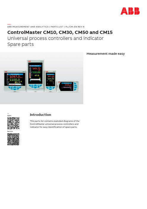
—A B B M E A SU R EM ENT A N D A N A LY TI C S | PA RTS LIS T | PL/CM -EN R E V NControlMaster CM10, CM30, CM50 and CM15Universal process controllers and indicator Spare partsMeasurement made easyIntroductionThis parts list contains exploded diagrams of the ControlMaster universal process controllers and indicator for easy identification of spare parts.—SalesService2CO NTRO LM A S TE R CM10, CM30, CM50 A N D CM15 SPA R E PA RTS | PL/CM R E V. N —Parts identificationCM10Figure 1 Identification of parts — CM103 CO NTRO LM A S TE R CM10, CM30, CM50 A N D CM15 SPA R E PA RTS | PL/CM R E V. NItem No.Description Part number 1Snap rivet B11780 2Battery B12792 3Type 1 function key (including items 1, 2, and 4)CM30/0706 4Function key support CM30/01205Mainboard CM30/0701 Mainboard (24 V DC)CM30/07026RS485 communications module upgrade kit CM30/0708 Ethernet communications module upgrade kit CM30/07097Option board 1a (1 relay)CM30/0703 Option board 1 (1 analog O/P, 2 digital I/O and 3 relays)CM30/07048Single panel clamp assembly CM10/0711 9Case moulding CM10/0056 10Thermistor assembly CM30/0052 11Panel seal CM10/0106 12Terminal cover CM10/0115 13Ethernet cable assembly CM30/0070P 14Bezel release tool CM30/0114 15Snap rivet B12722 16Bezel seal (including display dust gasket)CM10/0105 17Switch extender CM10/0107 18Bezel CM10/005319Membrane overlay CM10/0180 Membrane overlay (blank)CM10/018120O-ring B12794 21Light guide CM30/0112 22Display and processor board assembly CM10/0700Key to Figure 14CO NTRO LM A S TE R CM10, CM30, CM50 A N D CM15 SPA R E PA RTS | PL/CM R E V. N —...Parts identificationCM15Figure 2 Identification of parts – CM155 CO NTRO LM A S TE R CM10, CM30, CM50 A N D CM15 SPA R E PA RTS | PL/CM R E V. NItem No.Description Part number1Membrane overlay CM15/0180 Membrane overlay blank CM15/01812O-ring B12794 3Bezel moulding (including display dust gasket)CM15/0053 4Light guide CM30/0112 5Bezel seal CM10/0105 6Switch extender CM15/0107 7Display and processor board assembly CM15/0700 8Snap rivet B12722 9Type 1 function key (including items 11, 12 and 13)CM30/0706 10Type 2 function key CM30/0707 11Function key support CM30/0120 12Snap rivet B11780 13Battery B1279214Mainboard CM30/0701 Mainboard (24 V DC)CM30/070215Single panel clamp assembly CM10/0711 16Terminal cover CM10/0115 17Ethernet cable assembly CM30/0070P 18Panel seal CM10/0106 19Thermistor assembly CM30/0052 20Case assembly CM10/005621RS485 communications module upgrade kit CM30/0708 Ethernet communications module upgrade kit CM30/070922Option board 1a (1 relay)CM30/0703 Option board 1 (1 analog O/P, 2 digital I/O and 3 relays)CM30/070423Bezel release tool CM30/0114 Key to Figure 26CO NTRO LM A S TE R CM10, CM30, CM50 A N D CM15 SPA R E PA RTS | PL/CM R E V. N —...Parts identificationCM30Figure 3 Identification of parts – CM307 CO NTRO LM A S TE R CM10, CM30, CM50 A N D CM15 SPA R E PA RTS | PL/CM R E V. NItem No.Description Part number 1Snap rivet B11780 2Battery B12792 3Type 1 function key (including items 1, 2 and 5)CM30/0706 4Type 2 function key CM30/0707 5Function key support CM30/01206Mainboard CM30/0701 Mainboard (24 V DC)CM30/07027RS485 communications module upgrade kit CM30/0708 Ethernet communications module upgrade kit CM30/07098Option board 1a (1 relay)CM30/0703 Option board 1 (1 analog O/P, 2 digital I/O and 3 relays)CM30/07049Option board 2 (2 analog I/P and 4 digital I/O)CM30/0705 10Single panel clamp assembly CM30/0711 11Terminal cover CM30/0115 12Panel seal CM30/0106 13Thermistor assembly CM30/0052 14Ethernet cable assembly CM30/0070P 15Case assembly CM30/0056 16Bezel release tool CM30/0114 17Snap rivet B12722 18Bezel seal CM30/0105 19Switch extender CM30/0107 20Bezel assembly (including display dust gasket)CM30/005321Membrane overlay CM30/0180 Membrane overlay blank CM30/018122O-ring B12794 23Light guide CM30/0112 24Display and processor assembly CM30/0700Key to Figure 38CO NTRO LM A S TE R CM10, CM30, CM50 A N D CM15 SPA R E PA RTS | PL/CM R E V. N —...Parts identificationCM50Figure 4 Identification of parts – CM509 CO NTRO LM A S TE R CM10, CM30, CM50 A N D CM15 SPA R E PA RTS | PL/CM R E V. NItem No.Description Part number 1Type 1 function key (including items 2, 3 and 5)CM30/0706 2Snap rivet B11780 3Battery B12792 4Type 2 function key CM30/0707 5Function key support CM30/01206Mainboard CM50/0701 Mainboard (24 V DC)CM50/07027RS485 communications module upgrade kit CM30/0708 Ethernet communications module upgrade kit CM30/07098Option board 1 (2 analog I/P, 4 digital I/O, 1 analog O/P and 2 relays)CM50/0703 9Single panel clamp assembly CM30/0711 10Case assembly CM50/0056 11Panel seal CM50/0106 12Terminal cover CM50/0115 13Thermistor assembly CM30/0052 14Ethernet cable assembly CM30/0070P 15Bezel release tool CM30/0114 16Snap rivet B12722 17Display and processor board assembly CM50/0700 18Bezel seal CM50/0105 19Switch extender CM30/0107 20Bezel moulding (including display dust gasket)CM50/005321Membrane overlay CM50/0180 Membrane overlay blank CM50/018122O-ring B12794 23Light guide CM30/0112Key to Figure 410CO NTRO LM A S TE R CM10, CM30, CM50 A N D CM15 SPA R E PA RTS | PL/CM R E V. N—Service / Upgrade kitsCommonDescription Part number Type 1 function key upgrade kit CM30/0706 Type 2 function key upgrade kit CM30/0707 Rs485 communications upgrade kit CM30/0708 Ethernet communications upgrade kit CM30/0709 ConfigPilot PC configuration kit CM30/0715 IrDA bracket CM30/0716CM10, CM15 and CM30Description Part number Main board replacement kit CM30/0701 Main board replacement kit (24 V DC)CM30/0702 Option board 1a – single relay option upgrade kit CM30/0703 Option board 1 – 1 analog O/P, 2 digital I/O and 3 relay option upgrade kit CM30/0704CM10 and CM15Description Part number DIN rail mounting kit CM10/0715 Single panel clamp assembly CM10/0711CM30 and CM50Description Part number Single panel clamp assembly CM30/0711CM10Description Part number Display and processor board replacement kit CM10/0700CM15Description Part number Display and processor board replacement kit CM15/0700CM30Description Part number Display and processor board replacement kit CM30/0700 Option board 2 – 2 analog I/P and 4 digital I/O CM30/0705CM50Description Part number Display and processor board replacement kit CM50/0700 Main board replacement kit CM50/0701 Main board replacement kit (24 V DC)CM50/0702 Option board 1– 2 analog I/P, 1 analog O/P, 4 digital I/O and 2 relay option upgrade kit CM50/070311 CO NTRO LM A S TE R CM10, CM30, CM50 A N D CM15 SPA R E PA RTS | PL/CM R E V. NManualsDescription Part number User manual (base functionality) – CM10, CM30 and CM50IM/CM/B-EN User manual (standard functionality) – CM10, CM30 and CM50IM/CM/S-EN User manual (extended / dual functionality) – CM30 and CM50IM/CM/ED-EN User manual (indicator functionality) – CM15IM/CM/I-EN Communications supplement – CM10, CM15, CM30 and CM50IM/CM/C-EN PackagingDescription Part number CM30 and CM50 outer box CM30/0008 CM30 and CM50 outer box (unprinted)CM30/0009 CM30 and CM50 internal insert CM30/0010 CM10 and CM15 outer box CM10/0008 CM10 and CM15 outer box (unprinted)CM10/0009P L /C M R e v . N 05.2023—ABB Measurement & Analytics For your local ABB contact, visit:/contactsFor more product information, visit:/measurement—We reserve the right to make technical changes or modify the contents of this document without prior notice. With regard to purchase orders, the agreed particulars shall prevail. ABB does not accept any responsibility whatsoever for potential errors or possible lack of information in this document.We reserve all rights in this document and in the subject matter and illustrations contained therein. Any reproduction, disclosure to third parties or utilization of its contents – in whole or in parts – is forbidden without prior written consent of ABB.©ABB 2023All rights reserved.。
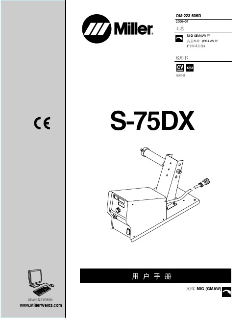
米勒中文用户手册
2006−01
工艺
MIG (GMAW) 焊 药芯焊丝 (FCAW) 焊 (气保或自保)
说明书
送丝机
S-75DX
请访问我们的网站
用户手册
文档: MIG (GMAW)
目录
第1部分:安全预防措施-使用前请阅读............................................................. 1 1-1. 符号使用..... . . . . . . . . . . . . . . . . . . . . . . . . . . . . . . . . . . . . . . . . . . . . . . . . . . . . . . . . . . . . . . . . . . . . . . . . 1 1-2. 电弧焊危险......... . . . . . . . . . . . . . . . . . . . . . . . . . . . . . . . . . . . . . . . . . . . . . . . . . . . . . . . . . . . . . . . . . . 1 1-3. 安装、操作和维护的其它符号................................ . . . . . . . . . . . . . . . . . . . . . . . . . . . . 3 1-4. (略)........................... . . . . . . . . . . . . . . . . . . . . . . . . . . . . . . . . . . . . . . . . . . . . . . . . . . . . . . . 3 1-5. 主要安全规范.............. . . . . . . . . . . . . . . . . . . . . . . . . . . . . . . . . . . . . . . . . . . . . . . . . . . . . . . . . . . . . 4 1-6. EMF电磁兼容信息. . . . . . . . . . . . . . . . . . . . . . . . . . . . . . . . . . . . . . . . . . . . . . . . . . . . . . . . . . . . . . . . . . . . . . 4
B&R贝加莱PLC资料

1.1 端子排 .................................................................................... 13 1.2 READY 继电器...................................................................... 13 1.3 拨码 PS476.PS6912.PS791 ................................................ 14 1.4 RS485-引脚定义 PS476,PS691,PS791 ................................ 14 2. CPU 模块-CP152 .............................................................................. 15 2.1 操作/连接组件 ........................................................................ 15 2.2 RS485/RS422/TTY 接口(IF2)................................................... 15 2.2.1 TTY 接口 符合 DIN66348 .............................................. 16 2.3 RS232 接口 IF1 ................................................................. 18
GPRS模块技术要求
南京普天通信科技有限公司外购件技术要求
名称:GPRS模块
编号:
版本:V1.0
类别: A类
拟制
采购
审核
批准
修改记录
.1 技术要求
1.1主要检验性能:
管脚定义:
1.2外观要求:
外观光洁,无划痕;标识清晰;包装或器件上应有厂家标识。
1.3外形尺寸:
单位:毫米;
2检验方法
厂家按批次供货时要随货提供检测报告,其各项指标应符合1.1条的要求。
入库前还要按下面要求进行检验:
2.1外观及外形尺寸检验:每块均须符合1.2和 1.3的要求。
2.2使用检验:每块接入车载终端,开机加电,在终端上设置好IP地址和终端ID 号,在SIM卡槽里插好SIM卡,在电脑上打开通信服务器软件,终端应能够上线收发短信及打电话。
3型号和指定厂家:
SIMCOM生产的SIM300CZ型GPRS模块。
上海移远通信技术有限公司生产的M10-TE-A型GPRS模块。
4检验及使用中注意事项
4.1拔插模块时,应对准插座,以免将模块插针弄歪。
4.2不要带电插拔SIM卡和GPRS模块。
智能电动机保护器使用说明书
5.7 250A 电流互感器外形尺寸..................................................................................................................................................12 5.7 800A 外置电流互感器外形尺寸..........................................................................................................................................13 5.8 漏电流互感器外形尺寸.......................................................................................................................................................13 5.9 显示模块外形尺寸...............................................................................................................................................................14 6 操作指南....................................................................................................................................................................................... 15 6.1 90L 显示模块面板................................................................................................................................................................15 6.2 显示操作说明........................................................................................................................................................................ 15 6.3 面板设置信息及菜单概述...................................................................................................................................................16 7 保护功能.....................................................................................................................................................................................24 7.1 过载保护................................................................................................................................................................................ 24 7.2 断相/不平衡保护.................................................................................................................................................................. 25 7.3 剩余电流保护(接地/漏电).............................................................................................................................................. 25 7.4 堵转保护................................................................................................................................................................................ 25 7.5 阻塞保护................................................................................................................................................................................ 25 7.6 欠载(欠流)保护...............................................................................................................................................................26 7.7 起动超时保护........................................................................................................................................................................ 26 7.8 欠压保护...............................................................................................................................................................................26 7.9 过压保护...............................................................................................................................................................................26 7.10 7.11 7.12 7.13 7.14 8 欠功率保护.........................................................................................................................................................................26 相序保护.............................................................................................................................................................................26 外部故障保护.....................................................................................................................................................................26 温度保护.............................................................................................................................................................................26
CMMI文件-T02 模块测试指导书模板

深圳市开拓技术设备有限公司Xxx模块测试指导书编号:KT-SP-ST-T02编制:审核:复核:批准:深圳市开拓技术设备有限公司发布历史修订记录目录1模块概述 (4)1.1模块基本信息 (4)1.2模块功能描述 (4)1.3模块使用场景 (4)1.4模块功能约束 (4)2模块设计 (4)2.1模块设计思路 (4)2.2模块详细设计 (4)2.3模块接口 (5)3模块测试分析和设计 (5)3.1测试分析 (5)3.2场景分析 (5)3.3功能分析和设计 (5)3.4兼容性分析和设计 (5)3.5可靠性分析和设计 (6)3.6性能分析和设计 (6)3.7安全性分析和设计 (6)3.8与其它特性交互分析和设计 (6)3.9自动化分析和设计 (6)1模块概述1.1模块基本信息描述模块的基本信息,必选1.2模块功能描述描述模块的基本功能,必选1.3模块使用场景从业务层面进行描述,什么人,什么时机,在什么场景下使用,期望达到什么样的效果1.4模块功能约束2模块设计2.1模块设计思路描述模块的基本设计思路,以及其与其它模块和特性交互分析,必选2.2模块详细设计描述模块的内部设计逻辑,包括但不限于时序图、UML、功能性设计以及非功能性设计等2.3模块接口描述模块提供的接口3模块测试分析和设计3.1测试分析主要从场景,功能,可靠性,性能,安全,易用性,交互等角度对模块进行分析和设计,以及模块测试策略3.2场景分析从user case角度,什么人,在什么时间,什么条件,怎么使用该功能。
分为场景1,2,3。
例如数据库的DML 操作模块,分为插入记录,删除记录,更新记录等场景。
每一场景中,务必分析大数据量、并发、异常等场景3.3功能分析和设计3.4兼容性分析和设计模块是否有兼容性方面的需求,比如UI要考虑浏览器的兼容性;驱动要考虑操作系统的兼容性3.5可靠性分析和设计模块是否有可靠性方面的需求,比如设备异常断电、断网的情况下的数据保障机制;网络连接不上的超时机制3.6性能分析和设计模块是否有性能方面的需求,比如是否存在大量并发用户访问的情况3.7安全性分析和设计模块是否有安全方面的需求,比如用户名密码传输、存储是否进行了加密3.8与其它特性交互分析和设计模块是和其它模块的交互,比如和数据库的交互3.9自动化分析和设计模块是需要进行自动化测试。
RCU 501 远程控制单元产品说明书

RCU501 is a high performance, general purpose, real-time process control computer for use in a wide variety of system applications in both on- and offshore installations. The processor core is an embedded Power PC™ architecture and the module is approved for Ex Zone 2 applications.Application types• Dynamic Positioning Systems• Thruster Control / Steering Systems • Navigation Sensor Integrator• Integrated Process Control Systems • Alarm and monitoring Systems • Safety SystemsFunction• Dual ethernet LAN process networks • Dual RedundancyNet interface for redundant RCU con fi guration• Dual Remote IO process BUS (RBUS) • 4 general purpose Digital Input channels • 4 general purpose Digital Output channels• 32 serial lines for 3rd party interface • 2 PROFIBUS channels for 3rd party interface• 2 CANBUS channels for 3rd party interfaceFeature• Single unit topology: SIL 1 compliant • Dual unit topology: SIL 2 and SIL 3compliant• Triple unit topology • Ex Zone 2 approved• Compliant to the following protocols:1. Modbus (Serial and TCP)2. NMEA 01833. PROFIBUS/PROFIsafe4. CAN/DeviceNet • 3rd party vendor speci fi c protocols are available upon request • Power:1. Redundant power input with power alarm monitoring2. Inrush current and over-voltage protection• Enhanced watchdog with fail-safe function and system status outputBene fi tsThe following built-in functions minimize system downtime:• Extended Built-in Self- Test (BIST) for computer diagnostics and fault identi fi cation during start-up and runtime • Prepared for online remote diagnostics • Prepared for online fi rmware upgrade • Bootable from fi le server or local fl ash memory• Easy installation and replacement 1. DIN Rail mounting2. All connections are pluggable3. 3 digit address switches• Hot swap in redundant applications,dual and triple Hot-Standby redundancy, 1oo2 redundancy• Status LED indication (Normal/Error)• RoHS compliantComputer performance• RCU501 performance is application dependant and governed by process complexity, updating frequency and number of interfaced I/O. Maximum updating frequency is 50 Hz.• Con fi guration guidelines:1. ESD/PSD: max. 800 I/O,F&G: max. 700 I/O both at scan rate: 1 Hz 2. Process/ Automation:max. 2000 I/O,design advice: 1280 I/O both at scan rate: 1 Hz3. Anti-surge: 3 loops, Scan rate: 50 Hz4. Dynamic Positioning: Tripleredundant DP system combined with Position Mooring. (Scan rate is adapted to signal processing and varies from 1 to 10 Hz).312729 Rev. B / September 2010KM article numberRCU501: 603439StandardsRCU501 complies with the following:• IACS E10• IEC 60533• IEC 60945• IEC 61508• IEC 62061Type approvalRCU501 is type approved by:• Det Norske Veritas (DNV)• The American Bureau of Shipping(ABS) • TÜV Rheinland• Wurldtech™; Achilles level 1certi fi edCE markingCE mark compliant, con fi rm to:• 2004/108/EC (EMC directive)• 94/9/EC (Atex directive)Ex certi fi cationEx nA II T4 (Zone 2)Environmental speci fi cationsAmbient temperatures and humidity:• Temp. Operation: -15˚C to 70˚C • Temp. Storage: -25˚C to 70˚C• Humidity Operation: Up to 98% RH • Humidity Storage: Up to 98% RH Protection Standards: IP 20DimensionsHeight: 355 mm Width: 158 mm Depth: 87 mm Weight: 1.35 kgCross point screw lock on DIN Rail T35 7.5/15 according to EN 50022ElectricalInput supply voltage: 24 VDC (+30%, -25%)Nominal current consumption: ≈ 0.8 A Start-up current: Max. 2.7 A Power consumption: Max. 20 W Heat dissipation: Max. 20 W Power connectors:• Screw terminals (slotted) • Cable cross section: 2.5 mm²Processor and memory Processor:• Type: Power PC TM host processorMPC8245• Clock frequency: 400 MHzMemory:• RAM size and speed: 64 MB @ 133MHz• PROM: 16 MB application fl ash-fi leSerial lineChannels: 32 insulated serial lines, distributed on 8 RJ45 connectors Physical layer: RS232, RS422 and RS485 Multidrop via RSER200Bit rate: Max. 115 kb/sGeneral purpose I/O channelsDigital Output (DO):• 4 x opto-isolated outputs• 1 x opto-isolated watchdog (forexternal interface)Digital Input (DI): 4 x opto-isolated inputsI/O connectors: • Cage clamps• Cable cross section: 1 mm²LAN interfaceProcess network & RedundancyNet: 2 x RJ45 Ethernet IEEE 802.3 type 10BASE-T/100BASE-TXRBUS interfaceConnector: 2 x RJ45Bit-rate: 2 Mb/sSignal code: Manchester encoded (Self-clocked)Copper wire topology:• Insulation: 500 V (Optocoupler)• Physical layer: RS485 Multidrop • Cable attenuation: < 6.5 db/100m @10 MHz (CAT 5)• Cable length: Max. 200 m betweenrepeaters. Max. 3 repeatersFibre optical topology (w/ additional fi bre media converter):• Fibre cable: 62.5/125 μm. Multimodus • Connector: ST • Cable length: Max. 1000 m (point to point). 500 m if used in patch-panel topology Field interfaceCAN interface:• 2 x CANopen/DeviceNet @ 5 polecage clamp terminals. 2.5 mm² cable • Bit rate: Max. 1 Mb/s. (DeviceNet notde fi ned above 500 kb/s)PROFIBUS interface:• 2 x opto-isolated 9 Pin femaleD-Sub connectors • Bit rate: Max. 12 Mb/sLife cycle predictionPredicted failure rate @ GB 25˚C (60% con fi dent, based on chip suppliers data): 24.2 YearsPredicted failure rate @ NS 35˚C(Environmental de-rating based on RomeLaboratory toolkit): 6.5 Years* KM reserves the right to make changes to the material or product described, at any time without notice.。
厦门才茂 CM510-62G 62C 无线传输终端 使用手册说明书

厦门才茂CM510-62G/62C无线传输终端使用手册厦门才茂通信科技有限公司厦门市软件园二期望海路23号之一3层电话:传真:邮政编码:361009网址: 版权所有2003-2018----才茂通信通畅天下----说明书声明版权声明:本使用说明书包含的所有内容均受版权法的保护,未经厦门才茂通信科技有限公司的书面授权,任何组织和个人不得以任何形式或手段对整个说明书和部分内容进行复制和转载,并不得以任何形式传播。
商标声明:、才茂、Caimore和其他才茂商标均为厦门才茂通信科技有限公司的商标。
本文档提及的其他所有商标或注册商标,由各自的所有人拥有。
注意:由于产品版本升级或其他原因,本文档内容会不定期进行更新。
除非另有约定,本文档仅作为使用指导,本文档中的所有陈述、信息和建议不构成任何明示或暗示的担保。
特别声明:产品说明书上的建议配置或者默认配置,不代表合适配置,客户须根据自己业务需要情况,调整成为适应自己业务开展的配置。
产品出厂的配置参数,仅供用户参考,用户收到设备时,不管有没有其他约定,用户必须全部检查一遍,并须根据自己项目和业务需求,自行调整配置好相关参数。
由于参数配置不当或者错误导致的问题,我司不承担任何责任。
同时,用户需要加强病毒攻击防范工作,因为病毒攻击导致的通信异常,我司不承担任何责任。
技术支持:地址:厦门市软件园二期望海路23号之一302网址:客服电话:************************客服传真:************客服邮箱:*******************版本说明文档版本修改说明发布日期作者签发V1.0第一次正式发布2016.1.15Luot LiugbV1.2增加CDMA、短信配置2016.6.25Luot LiugbV1.3增加下装程序和配置方式2019.4.29Liugb LiugbV1.4增加注册包心跳包说明2019.06.05LiugbLiugb目录目录 (4)第一章产品简介 (5)1.1产品概述 (5)1.2系统组成 (6)1.3产品特点 (6)1.4产品功能 (6)1.5工作原理 (7)1.6技术参数 (7)第二章安装 (8)2.1概述 (8)2.2接线 (8)2.3接口说明 (10)第三章下装程序 (12)3.1下装程序 (12)第四章配置方式 (15)4.1本地串口配置参数 (15)4.2远程配置参数 (16)4.3短信配置IP端口(对端手机号发短信给DTU) (19)4.4注册包配置 (19)4.5心跳包配置 (20)第五章性能测试 (21)5.1供电电源 (21)5.2检测网络情况 (21)附件一:AT指令 (21)附件二:设备功耗 (22)附件三:接口类型 (22)附件四:常见故障分析 (22)附件五:TCP才茂协议文档 (23)附件六:网络参数表格 (23)第一章产品简介1.1产品概述CAIMORE低功耗CM510-62G/62C DTU(Data Transfer Unit,全称数据传输单元,本文简称DTU,下文62G/62C 简称62X)是一款为用户提供低功耗、高速、永远在线、TCP透明数据传输的工业级无线终端设备,最低功耗达到10mA@+9VDC。
195-2011 中国联通M2M UICC卡技术规范V2.0
I
中国联通 M2M UICC 卡技术规范 v2.0
6.2.1.2 封装顶部的方向标....................................................................................................................... 11 6.2.2 MFF2 ..................................................................................................................................................... 11
6.2.1 MFF1 ....................................................................................................................................................... 9 6.2.1.1 封装底部的方向标....................................................................................................................... 11
多功能模块贴片机CM301学习手册含CM402维护PPT课件

机器本体使用气压
气压校准表使用 1.如左图,阀门往上解除;之后
即可左右旋转调整;再之后 阀门压下即可锁住. 2.确认机器本体使用气压 0.5MPa以上; 3.确认托盘供料器TRAY 使用气压 0.3MPa以上.
28
1.2.2 清洁线性相机玻璃盖
遮蔽板
1.关闭伺服开关;
2.打开机器的安全盖;
3.清洁玻璃盖的上表面.
主要的须润滑的部件
线性滑轨
丝杆
轴承
滑轨的润滑
1.将滑块推至滑轨末端; 2.用干净的布清除旧油; 3.注油润滑; a.注油嘴,可通过油枪加油; b.无油嘴,直接将油涂抹于滑
轨的凹槽内; 4.全程慢速运行滑快组件.
27
1.2 每天检查项目
1.2.1 检查机器供给压及废水回收瓶
托盘供料器TRAY 使用气压
2.装入新的PAD.
41
7. 安放吸嘴
1.关上安全盖,并将伺服开关打至 ON的位置;
2.点击
下页
3.关闭伺服开关,并打开安全盖; 42
4.旋转角度STOPPER,使其面对 操作方;
窄 宽
8.再次检查吸嘴安排位置
5.安装吸嘴. *注意吸嘴的方向,窄沟嵌入 STOPPER内.
将吸嘴重新正确排放
43Biblioteka 1.3.3 清洁吸嘴交换台
1.关闭伺服开关; 2.打开机器的安全盖; 3.清空元件回收盒.
NG元件回收盒
1.2.6 清洁托盘供给器的NG元件回收盒
1.拉出回收盒; 2.清空及回收元件; 3.将回收盒推入回位.
NG元件回收盒 31
1.2.7 清洁料带箱 有切刀系统
1. 打开切刀外盖; 2. 拉出料带箱; 3. 清空料带. 切刀外盖
E18系列产品规格书说明书
E18系列产品规格书CC25302.4GHz ZigBee3.0无线模块目录第一章产品概述 (3)1.1产品简介 (3)1.2特点功能 (4)1.3应用场景 (5)第二章规格参数 (6)2.1射频参数 (6)2.2电气参数 (6)2.3硬件参数 (6)2.4网络系统参数 (7)第三章机械尺寸与引脚定义 (8)第四章硬件设计 (11)第五章软件设计 (11)第六章常见问题 (13)6.1传输距离不理想 (13)6.2模块易损坏 (13)6.3误码率太高 (13)第七章焊接作业指导 (7)7.1回流焊温度 (7)7.2回流焊曲线图 (7)第八章相关型号 (8)第九章天线指南 (8)第十章产品包装图 (8)修订历史 (9)关于我们 (9)第一章产品概述1.1产品简介E18系列是亿佰特设计生产的2.4GHz频段的ZigBee通信协议转串口无线模块,贴片型,PCB板载天线或IPEX-1接口,引脚间距1.27mm,出厂自带自组网固件,到手即用,适用于多种应用场景(尤其智能家居)。
E18系列模块采用美国德州仪器公司原装进口CC2530射频芯片,芯片内部集成了8051单片机及无线收发器,部分模块型号内置PA功率放大器增加通信距离。
出厂自带固件基于ZigBee3.0协议实现的串口数据透传,支持ZigBee3.0协议下各种指令命令。
经实测,对市面上大多数ZigBee3.0产品有着非常良好的兼容性。
1.2ZigBee 3.0优势E18系列模块固件基于Z-Stack3.0.2协议栈(ZigBee 3.0),该版本为CC2530/CC2538系列芯片最优协议栈,因此我司也此基础上做了许多优化,确保系统长期稳定运行。
ZigBee3.0与早前版本的应用方式区别:1.组网方式发生变化:ZigBee 3.0取缔了一上电就组网的方式,而是根据实际需要进行组网。
任何设备在出厂状态下是无网络状态,协调器需要运行“formation”(调用bdb_StartCommissioning(BDB_COMMISSIONING_MODE_NWK_FORMATION))来新建网络,然后再运行"Steering"(调用bdb_StartCommissioning(BDB_COMMISSIONING_MODE_NWK_STEERING))打开网络,打开网络默认时间180秒,可通过广播"ZDP_MgmtPermitJoinReq"的方式将打开网络提前关闭。
TH-CMMB-TC7902模组规格书

1.1
■插座式CMMB模组,全面兼容CMMB标准;
■频率范围(470MHZ ~794MHz);
■尺寸: 40(长) x 38(宽) x 5.0(高) mm;
■模拟视频输
■I2C总线/UART/遥控接收控制;
■体积小,功耗低,接口简单,方便与主系统搭配;
■高灵敏度(QPSK 1/2 LDPC输入电平<-97dBm);
6
6
6
70
℃
TI
限制工作温度
-20
85
℃
5.3
电性参数
最小
典型
最大
单位
灵敏度(QPSK 1/2 LDPC编码条件下)
-97
-98.5
-99.5
dBm
音频信噪比
85
dB
音频输出电平
0.95
V
视频输出电平
0.85
Vp-p
备注:
1)、射频线的线芯需要做50欧姆的阻抗;
2)、包络线芯的屏蔽线需要是网状的铜线;
3)、射频线上的接口座中有两弹片,弹片需要是铜片,而且要镀金。
3.3V(Typ)
最大工作电流
3.3V(200mA);
最大功耗
0.67W
输入阻抗
50ohm
控制接口电平
UART/IR电平为3.3V
5.2
参数
描述
最小
典型
最大
单位
3.3V
3.3V供电
3.0
3.3
3.5
V
1.8V
1.8V供电
1.7
1.8
1.9
V
电源纹波
电源纹波要求
2.0
mVp-p
Ta
产品规格书

控制方式
同步控制伎持双备份
10
控制距离
超五类双绞网线,超过100米使用光纤传输
11
软件接口
Windows
12
信号输入
RJ45
(7)屏体运行参数
1
工作电压
AC:n0V~240V∖50~60Hz伎持双备份
2
峰值功率
≤400W∕m2
3
平均功率
100W∕m2〜180W∕m2
4
连续工作时间
≥7×24hrs,支持连续不间断显示
1
LED种类
SMD1515
2
像素点间距
1.875mm
3
像素点组成
IRlGlB
(3)模组技术参数
1
模组分辨率(宽*高)
160像素*90像素
2
模组尺寸(宽X高)
(宽)30Ommχ(高)168.75mm
3
模组信号输入
支持精密镀金接插件直连
4
模组电源输入
支持精密镀金接插件直连
5
模组数据存储
支持数据存储
6
电磁兼容
5
平均无故障工作时间
>1000H
6
LED寿命
10万小时
7
离散失控点
<0.001,出厂时为0
8
连续失Hale Waihona Puke 点09盲点率
≤0.001,出厂时为0
10
屏幕温升(使用运行状态)
M5度
11
运彳再境温度
-10℃-60℃
12
运行环境湿度
10%~90%RH,猿结
注:参数指标根据项目的具体情况会有变化(产品按照提交合同规格书为准)
模块井模块尺寸

模块井模块尺寸
模块井(或称作驱动端口,基本块,模块化单元等)的尺寸通常是由具体的模块化系统或模块化工具进行定义的,不同的系统或工具可能会有不同的尺寸规格。
一些常见的模块化系统或工具的模块尺寸及其标准包括:
1.贝尔实验室的CARP(组成模块:1.6英寸x
2.2英寸)。
2.元器件可插拔规范(PICMG):-单板计算机/嵌入式计算机尺寸:
3.5"x
4.5",4.0"x4.0",
5.75"x8.0"。
-微ATX、标准ATX规格:9.0"x12.0"。
-高级TCA规格(硬件阵列板):14.0"x15.0"。
3. Arduino:2.7 x 2.1英寸(Arduino Uno),3.0 x 1.7英寸(Arduino Nano)。
4. 费城分组计算机的Qbus系统:6.25英寸 x 10.5英寸。
5.香港生产力局的恒基电子板规范:1.5英寸x2.5英寸,2.0英寸x2.0英寸,2.5英寸x2.5英寸。
需要注意的是,这些尺寸标准都不是绝对的,有些实际使用的模块尺寸甚至没有一个标准。
因此,在选择模块化系统或工具时,需要先了解其所支持的模块尺寸以及是否满足自己的需求。
黑视(BlackVue)CM100LTE外部连接模块说明书

BLACKVUE CM100LTEIn the boxCheck the box for each of the following items before installing the BlackVue device.CM100LTE3At a glanceThe following diagram explains details of the external connectivity module.4BLACKVUECM100LTE 5Install and power upInstall the connectivity module at top corner of the windshield. Remove any foreign matterand clean and dry the windshield before installation.Warningy Do not install the product in a location where it can obstruct the driver's field ofvision.Turn off the engine.Unscrew the bolt that locks the SIM slot cover on connectivity module. Remove the cover, and unmount the SIM slot using the SIM eject tool. Insert the SIM card into theslot.6BLACKVUEPeel off the protective film from the double-sided tape and attach the connectivitymodule to the top corner of the windshield.Connect the front camera (USB port) and the connectivity module cable (USB).Use the pry tool to lift the edges of the windshield trim/molding and tuck in theconnectivity module cable.Turn on the engine. The BlackVue dashcam and connectivity module will power up.Notey For full details on installing the dashcam on your vehicle, refer to the "Quick Start Guide" that is included in the BlackVue dashcam package.y SIM card must be activated to use LTE service. For details, refer to the SIM Activation Guide.Product specificationsCM100LTECM100LTE7APPENDIX – PRODUCT SPECIFICATIONCM100LTEFunction Operating Frequency Output Power UMTS FDD 11920-1980 MHz24.00 dBm UMTS FDD 8880-915 MHz24.00 dBmE-UTRA FDD 11920-1980 MHz23.00 dBmE-UTRA FDD 31710-1785 MHz23.00 dBmE-UTRA FDD 72500-2570 MHz23.00 dBmE-UTRA FDD 8880-915 MHz23.00 dBmE-UTRA FDD 20832-862 MHz23.00 dBm8BLACKVUEProduct WarrantyT he term of this product warranty is 1 year from the purchase date. (Accessories such as an External Battery/microSD Card: 6 Months)W e, PittaSoft Co., Ltd., provide the product warranty according to the Consumer Dispute Settlement Regulations (drawn upby the Fair Trade Commission). PittaSoft or designated partners will provide the warranty service upon request.DR750X-2CH IR, DR900X-2CH IRFCC ID: YCK-CM100LTE / Contains FCC ID: XMR201605EC25A / Contains IC ID: 10224A-201611EC25A Declaration of ConformityPittasoft declares that this device complies with the essential requirements and relevant provisions of Directive 2014/53/EUGo to /doc to view the Declaration of Conformity.©CM100LTEExternal Connectivity Module /blackvueofficialAddress4F ABN Tower, 331, Pangyo-ro, Bundang-gu, Seongnam-si, Gyeonggi-do, Republic of Korea, 134882020。
整理产品规格书模板_产品规格书

产品规格书模整理人尼克板产品规格书ZG-5000-EIEEE802.11 g室外无线网桥1.版本修订2.产品规格1.硬件规格ZG-5000-E的硬件规格见下表:表1 硬件规格2.软件规格ZG-5000-E的软件规格见下表:表2 软件规格1.物理规格ZG-5000-E的物理规格见下表:表3 物理规格2.环境规格ZG-5000-E的环境规格见下表:表4环境规格3.安规/国家认证4.包装规格1.1.0.4″六位米字数码管2.红色发光3.黑面白胶,共阴显示2.用途数字显示3.极限参数(T A=25℃)注:脉冲宽度0.1ms,占空比1/10,防静电使用,焊接时间在2-3秒之间,使用环境保持干燥通风。
4.光电参数(T A=25℃)5.线路图、外形尺寸其余公差:±0.25单位:mm 6.晶片特性曲线:产品规格书Product Specification客户名称:产品型号:LS-SMD-42WP4LB-DMX512-03产品名称:Φ42全彩贴片点光源产品描述:SMD5050 4灯全彩点控DC15V PC注塑深圳市银幕光电科技有限公司Shenzhen LEDSigns Technology Co.,Ltd地址:深圳市宝安区石岩镇洲石路明金海第二工业园A栋三楼Adress:3F, Block A,Min Jin Hai 2nd Industrial park, Zhoushi Road, Bao’an District, Shenzhen.一、产品特点★美观,高端,大方,典雅;★灯珠采用超高亮度贴片5050光源,绿色安全、节能环保;★基于 SMD 贴片特性,光衰小,发光角度≥120°,一致性好;★一体化卡扣式无接头防拽连接设计;★采用德国进口高导热胶全灌封防水设计,不易发黄,具有全防水、防腐、防酸碱、抗UV,防护等级为 IP67,增强了产品的使用寿命和适应性;★产品呈柔性,应用灵活,多种安装方式可选。
CM模块Transparent CAN应用指南

硬件组态
运行Demo程序,在设备组态界面右键点击CPU然后选择“更改设备类 型”,在弹出的界面选择实际连接的PLC型号并点击 “确定”按钮:
硬件组态
双击更改后的CPU,在系统和时钟存储器界面中勾选“启用时钟存储器字 节”,定义时钟存储器字节的地址为MB0:
硬件组态
双击CPU左侧的CM模块,在Module parameters界面中设定传输的波特 率,操作模式为Transparent CAN :
程序处理- Leabharlann 收报文 打开“Transparent CAN_DB”数据块,设定用于控制CAN报文接收相关 参数的启动值:
程序处理-接收报文
在“Receive&Send Data”数据块中分别创建数据类型为“SCANFrame” 的4个变量,用于存储CM模块接收的CAN报文数据:
程序处理-接收报文
通讯测试
保存配置并进行编译下载,下载完成后CM模块RUN灯连续3次绿闪。 创建新的监控表,添加S_CANFrames 中的相关变量并进行赋值:
通讯测试
运行MiniMon软件,点击 图标开始监控,此时可以看到MiniMon软件 接收到CM模块发送的4条CAN报文 : ID分别为201h、202h 、203h和204h ,发送周期为200ms
程序处理- 程序结构说明
Demo例程中的程序结构说明:
程序块
FC100 Transparent CAN
FC101 Upload_ReceiveFrames FC102 Download_SendFrames DB100 Receive&Send Data DB106 Transparent CAN_DB CM_CANMode_Group 用于CM实现CAN报文传 输的基本程序块组
- 1、下载文档前请自行甄别文档内容的完整性,平台不提供额外的编辑、内容补充、找答案等附加服务。
- 2、"仅部分预览"的文档,不可在线预览部分如存在完整性等问题,可反馈申请退款(可完整预览的文档不适用该条件!)。
- 3、如文档侵犯您的权益,请联系客服反馈,我们会尽快为您处理(人工客服工作时间:9:00-18:30)。
描述
CMMB 474MHZ ~ 885MHZ
3.3V(Typ) 3.3V(450mA) 50ohm(请采用无源天线) 40.0(宽) x 38.0(长) x 5.2(高)mm
UART/IR CVBS,NTSC,1Vp-p(75ohm)
■ 工作条件
参数
3.3V 电源纹波
Ta Tstg
描述
3.3V 供电 电源纹波要求 正常工作温度范围 存储工作温度
最小
3.0
-20 -40
典型
3.3 20
最大
3.5
80 85
单位
V mVp-p
℃ ℃
■ 电气参数
参数
Z in F RF Sensitvity
描述
输入阻抗 射频输入频率范围 灵敏度(QPSK1/2 LDPC 编码条件下)
最小
474 -95
典型
50
最大
885 -100.0
单位
Ω MHZ dBm
8.天线保护
描述 +3.3V Power +3.3V Power Ground
CON1
模块连接口 20PIN 1.27mm 单排
插座
J3 天线口
4 5 6 7 8 9 10 11 12 13 14 15 16 17 18
19
20
PIN 脚 1 2 3 4 5 6 7 8 9 10 11 12 13 14 15 16 17 18 19 20
Video encoder
Audio DAC
FLASH WATCH DOG/LVD
CAS IR
POWER +1.8V/+3.3V
4.产品尺寸和视图
■ 尺寸:40.0(宽) x 38.0(长) x 5.2(高)mm
5.连接器 PIN 脚定义
J1
SD 软件升级和 CA 小卡座
9PIN 0.5mm FPC 座 子
■ 视频输出:CVBS
■ 音频输出:I2S( 44.1Khz, 48Khz,32Khz,24Khz)
■ UART/IR ■ 内置上电和低电压复位电路
■ 高灵敏度:-95dBm~-100dBm ■ 输入电压:+ 3.3V,+ 1.8V ■ 内置 SMD 加密 IC ■ 尺寸:40.0(宽) x 38.0(长) x
CON2 模块连接口 20PIN 1.27mm 单排
插座
PIN 脚 1 2 3 4 5 6 7 8 9
PIN 脚 1 2 3
定义 VDD-OUT GND SD_CLK SD_CMD SD_D0 SD_D1 SD_D2 SD_D3 SD_DET
定义 +3.3VA +3.3VA GND
描述 3.3V-OUTPUT 地 TF 卡时钟脚 TF 卡命令/复位脚 TF 卡数据脚 TF 卡数据脚 TF 卡数据脚 TF 卡数据脚 TF 卡检测脚
1.产品特性
■ 插座式 CMMB 模组,完全符合 CMMB 标准 GY/T220.1-2006 和 GY/T 220.2-2006 ■ 频率范围(474MHZ ~ 885MHZ) ■ 调制方式:支持 BPSK, QPSK, 16QAM
■ 带宽:8M
■ 模拟和数字音频输出
■ 视频制式:支持NTSC 和 PAL
PIN 脚 1
NC NC GND /RESET IR_IN GND AOUT_R AOUT_L GND SCLK LRCK MCLK SDATA GND UART_RX
UART GND NC NC GND NC NC GND NC GND NC SD_DET SD_DATA3 SD_DATA2 SD_DATA1 SD_DATA0 SD_CMD SD_CLK GND
5.2(高)mm
2.应用场合
■ 车载导航系统 ■ 移动电视,车载电视 ■ PMP,PDA,MP3/4P ■ CMMB 机顶盒 ■ 所有 CMMB 的手持和便携式产品
3.原理方框图
Demux
TUNER+DEMOD
Video decoder Audio decoder
Disp Engine
I2S IF
ARM9 Process
CMMB 移动数字电视模块规格书
完全符合 CMMB 标准 GY/T220.1-2006 和 GY/T 220.2-2006
型号:CM501-01
2010-07-07 版本:v0.2
变更记录
1.2010.04.25 v0.1 初始版本 2.2010.07.07 v0.2 版本 2.1 增加了 SD 引脚 2.2 优化 1.8V 电源
(不能接上拉)
Universal Asynchronous
(不能接上拉)
Ground
描述 Ground Analog Video Out Ground Reserve Reserve Ground
Ground NC Ground NC SD 卡 SD 卡 SD 卡 SD 卡 SD 卡 SD 卡 SD 卡 Ground
天线接口
描述
6.音视频输出
6.1 视频输出格式
■ 模拟视频(CVBS)输出 ■ CCIR656 数字视频输出
6.2 音频输出格式
■ 模拟左右声道音频输出 ■ I2S 数字音频输出:支持 32KHZ,44.1KHZ,48KHZ(默认)采样频率
7.电气性能
■ 常规特性
项目名称
接收对象 频率范围 工作电压 最大工作电流 天线输入阻抗 结构尺寸 控制接口 视频信号
定义 ANT
NC NC Ground External Reset(低电平有效) Remoter Control Input Ground Analog Audio Right Out Analog Audio Left Out Ground I2S I2S I2S I2S Ground Universal Asynchronous
对外天线接口能够分别在接地、接 12V 电源 60 秒模块无损坏。恢复到正常连接状态后, 能够正常工作,并能发挥出全部规定的功能。
9.控制协议
9.1 遥控码控制:
遥控格式:NEC 格式 详细控制协议,请联系我们。
9.2 串口控制协议
采用标准 UART 通信接口,逻辑电平为 5V TTL 电平,UART 工作在 8N1 模式,即 8 位数据位, 无奇偶校验, 一切停止位,波特率固定在 115200bps。 详细控制协议,请联系我们。
