5082-3351-EC000中文资料
5082-2800中文资料

Schottky Barrier Diodes for General Purpose ApplicationsTechnical DataFeatures• Low Turn-On VoltageAs Low as 0.34 V at 1 mA• Pico Second Switching Speed • High Breakdown VoltageUp to 70 V• Matched Characteristics AvailableDescription/Applications The 1N5711, 1N5712, 5082-2800/ 10/11 are passivated Schottky barrier diodes which use a patented “guard ring” design to achieve a high breakdown voltage. Packaged in a low cost glass package, they are well suited for high level detecting, mixing, switching, gating, log or A-D converting, video detecting, frequency discriminating, sampling, and wave shaping.The 5082-2835 is a passivatedSchottky diode in a low cost glasspackage. It is optimized for lowturn-on voltage. The 5082-2835 isparticularly well suited for theUHF mixing needs of the CATVmarketplace.The 5082-2300 Series and5082-2900 devices are unpas-sivated Schottky diodes in a glasspackage. These diodes haveextremely low 1/f noise and areideal for low noise mixing, andhigh sensitivity detecting. Theyare particularly well suited for usein Doppler or narrow band videoreceivers.1N57111N57125082-2300 Series5082-2800 Series5082-2900DIMENSIONS IN MILLIMETERS AND (INCHES).Outline 15Maximum RatingsJunction Operating and Storage Temperature Range5082-2303, -2900.................................................................-60°C to +100°C 1N5711, 1N5712, 5082-2800/10/11....................................-65°C to +200°C 5082-2835............................................................................-60°C to +150°C DC Power Dissipation(Measured in an infinite heat sink at T CASE = 25°C)Derate linearly to zero at maximum rated temperature5082-2303, -2900..............................................................................100 mW 1N5711, 1N5712, 5082-2800/10/11.................................................250 mW 5082-2835.........................................................................................150 mW Peak Inverse Voltage.................................................................................V BRPackage CharacteristicsOutline 15Lead Material........................................................................................DumetLead Finish..............................................................................95-5% Tin-LeadMax. Soldering Temperature................................................260°C for 5 secMin. Lead Strength....................................................................4 pounds pullTypical Package Inductance1N5711, 1N5712:................................................................................2.0 nH2800 Series:........................................................................................2.0 nH2300 Series, 2900:..............................................................................3.0 nHTypical Package Capacitance1N5711, 1N5712:................................................................................0.2 pF2800 Series:........................................................................................0.2 pF2300 Series, 2900:............................................................................0.07 pFThe leads on the Outline 15 package should be restricted so that thebend starts at least 1/16 inch from the glass body.Outline 15 diodes are available on tape and reel. The tape and reelspecification is patterned after RS-296-D.Electrical Specifications at T= 25°CAGeneral Purpose DiodesMin.Max.V F = 1 V Max.Max.Max.Breakdown Forward at Forward Reverse Leakage Capaci-Part Package Voltage Voltage Current Current tance Number Outline V BR (V)V F (mV)I F (mA)I R (nA) at V R (V)C T (pF) 5082-280015704101520050 2.0 1N571115704101520050 2.0 5082-281015204103510015 1.2 1N571215205503515016 1.2 5082-28111515410201008 1.2 5082-2835158*34010*1001 1.0 Test I R = 10 µA I F = 1 mA*V F = 0.45 V V R = 0 V Conditions*I R = 100 µA f =1.0 MHz Note: Effective Carrier Lifetime (τ) for all these diodes is 100 ps maximum measured with Krakauer method at 5 mA except for 5082-2835 which is measured at 20 mA.Low 1/f (Flicker) Noise DiodesMin.Max.V F = 1 V Max.Max.Max.Part Breakdown Forward at Forward Reverse Leakage Capaci-Number Package Voltage Voltage Current Current tance 5082-Outline V BR (V)V F (mV)I F (mA)I R (nA) at V R (V)C T (pF) 230315204003550015 1.0 29001510400201005 1.2 Test I R = 10 µA I F = 1 mA V R = 0 V Conditions f =1.0 MHzNote: Effective Carrier Lifetime (τ) for all these diodes is 100 ps maximum measured with Krakauer method at 20 mA.Matched Pairs and QuadsBasic Matched MatchedPart Number Pair Quad Batch5082-Unconnected Unconnected Matched[1]Test Conditions2900∆VF at IF= 1.0, 10 mA28005082-28045082-2805∆V F at I F = 0.5, 5 mA ∆V F = 20 mV∆V F = 20 mV*I F = 10 mA∆C O at f = 1.0 MHz28115082-2826∆VF at IF= 10 mA∆V F = 10 mV∆C O at f = 1.0 MHz ∆C O = 0.1 pF28355082-2080∆VF at IF=10 mA∆V F = 10 mV∆C O at f = 1.0 MHz∆C O = 0.1 pFNote:1. Batch matched devices have a minimum batch size of 50 devices.SPICE ParametersParameter Units5082-28005082-28105082-28115082-28355082-23035082-2900B V V75251892510C J0pF 1.60.8 1.00.70.7 1.1E G eV0.690.690.690.690.690.69I BV A10E-510E-510E-510E-510E-510E-5I S A 2.2 x 10E-9 1.1 x 10E-90.3 x 10E-8 2.2 x 10E-87 x 1.0E-910E-8N 1.08 1.08 1.08 1.08 1.08 1.08 R SΩ25101051015 P B V0.60.60.60.560.640.64 PT222222 M0.50.50.50.50.50.5Typical ParametersV F – FORWARD VOLTAGE (V)Figure 1. I-V Curve Showing Typical Temperature Variation for 5082-2300 Series and 5082-2900 Schottky Diodes.1001010.10.01I F - F O R W A R D C U R R E N T (m A )V BR (V)Figure 2. 5082-2300 Series Typical Reverse Current vs. Reverse Voltage at Various Temperatures.10.0001,000100101I R (n A )051015100755025T A = 25°CI F - FORWARD CURRENT (mA)Figure 3. 5082-2300 Series and 5082-2900 Typical Dynamic Resistance (R D ) vs. Forward Current (I F ).100010010R D - D Y N A M I C R E S I S T AN C E (Ω)0.01010100V R - REVERSE VOLTAGE (V)Figure 4. 5082-2300 and 5082-2900 Typical Capacitance vs. Reverse Voltage.1.21.00.80.60.40.20C T - C A P A C I T A N C E (p F )048121620V F - FORWARD VOLTAGE (V)Figure 5. I-V Curve Showing Typical Temperature Variation for 5082-2800 or 1N5711 Schottky Diodes.5010510.50.10.050.01I F - F O R W A R D C U R R E N T (m A )00.20.40.60.8 1.0 1.2V R - REVERSE VOLTAGE (V)Figure 6. (5082-2800 OR 1N5711) Typical Variation of Reverse Current (I R ) vs. Reverse Voltage (V R ) at Various Temperatures.100,00010,0001000100101I R - R E V E R S E C U R R E N T (n A )0.20.40.60.81.01.2V R - REVERSE VOLTAGE (V)Figure 7. (5082-2800 or 1N5711)Typical Capacitance (C T ) vs. Reverse Voltage (V R ).12.01.51.00.50C T - C A P A C I T A N C E (p F )010********V F - FORWARD VOLTAGE (V)Figure 8. I-V Curve Showing Typical Temperature Variation for the 5082-2810 or 1N5712 Schottky Diode.100101.00.10.01I F - F O R W A R D C U R R E N T (m A )V R - REVERSE VOLTAGE (V)Figure 9. (5082-2810 or IN5712)Typical Variation of Reverse Current (I R ) vs. Reverse Voltage (V R ) at Various Temperatures.10,0001000100101.0I R - R E V E R S E C U R R E N T (n A )Typical Parameters, continuedV F - FORWARD VOLTAGE (V)Figure 10. I-V Curve Showing Typical Temperature Variation for the 5082-2811 Schottky Diode.100101.00.10.01I F - F O R W A R D C U R R E N T (m A )0.40.20.60.81.01.2V R - REVERSE VOLTAGE (V)Figure 11. (5082-2811) Typical Variation of Reverse Current (I R ) vs. Reverse Voltage (V R ) at Various Temperatures.100,00010,0001000100101I R - R E V E R S E C U R R E N T (n A )0510********V F - FORWARD VOLTAGE (V)Figure 12. I-V Curve Showing Typical Temperature Variations for 5082-2835 Schottky Diode.100101.00.10.01I F - F O R W A R D C U R R E N T (m A )00.20.40.60.8 1.0 1.2V R - REVERSE VOLTAGE (V)Figure 13. (5082-2835) Typical Variation of Reverse Current (I R ) vs. Reverse Voltage (V R ) at Various Temperatures.100,00010,0001000100101I R - R E V E R S E C U R R E N T (n A )0123456V R - REVERSE VOLTAGE (V)Figure 14. Typical Capacitance (C T ) vs. Reverse Voltage (V R ).C T - C A P A C I T A N C E (p F )0246810I F - FORWARD CURRENT (mA)Figure 15. Typical Dynamic Resistance (R D ) vs. Forward Current (I F ).1000100101R D - D Y N A M I C R E S I S T A N C E (Ω)Diode Package Marking1N5xxx5082-xxxxwould be marked:1Nx xxxxx xxYWW YWWwhere xxxx are the last four digits of the 1Nxxxx or the 5082-xxxx partnumber. Y is the last digit of the calendar year. WW is the work week ofmanufacture.Examples of diodes manufactured during workweek45 of 1999:1N57125082-3080would be marked:1N53071280945945Data subject to change.Copyright © 1999 Agilent TechnologiesObsoletes 5968-4304E5968-7181E (11/99)。
5082-7402-CE300中文资料

7.6 mm (0.3 inch) Micro Bright Seven Segment Displays Technical DataFeatures• Available with Colon for Clock Display • Compact Package 0.300 x 0.500 inchesLeads on 2.54 mm (0.1 inch)Centers• Choice of Colors AlGaAs Red, HighEfficiency Red, Yellow, Green,Orange• Excellent Appearance Evenly Lighted Segments Mitered Corners on Segments Surface Color Gives Optimum Contrast±50° Viewing Angle • Design FlexibilityCommon Anode or Common CathodeRight Hand Decimal Point ±1. Overflow Character • Categorized for Luminous IntensityYellow and Green Categorized for ColorUse of Like Categories Yields a Uniform Display • High Light Output • High Peak Current• Excellent for Long Digit String Multiplexing • Intensity and Color Selection Available See Intensity and ColorSelected Displays Data Sheet • Sunlight Viewable AlGaAsDescriptionThe 7.6 mm (0.3 inch) LED seven segment displays are designed for viewing distances up to 3 metres (10 feet). These devices use an industry standard size package and pinout. Both the numeric andDevicesOrange AlGaAs [1]HER [1]Yellow [1]Green [1]Package HDSP-HDSP-HDSP-HDSP-HDSP- DescriptionDrawingA401A151750174017801Common Anode Right A Hand Decimal750274027802Common Anode Right Hand B Decimal, Colon A403A153750374037803Common Cathode Right C Hand Decimal750474047804Common Cathode Right Hand D Decimal, ColonA157750774077807Common Anode ±1. Overflow E A158750874087808Common Cathode ±1. OverflowFNote:1. These displays are recommended for high ambient light operation. Please refer to the HDSP-A10X AlGaAs, HDSP-335X HER, HDSP-A80X Yellow, and HDSP-A90X Green data sheet for low current operation.HDSP-740x Series HDSP-750x Series HDSP-780x Series HDSP-A15x Series HDSP-A40x Series±1. overflow devices feature a right hand decimal point. All devices are available as either common anode or common cathode.These displays are ideal for most applications. Pin for pin equiv-alent displays are also available in a low current design. The low current displays are ideal forportable applications. For additional information see the Low Current Seven Segment Displays.Part Numbering SystemNotes:1. For codes not listed in the figure above, please refer to the respective datasheet or contact your nearest Agilent representative for details.2. Bin options refer to shippable bins for a part number. Color and Intensity Bins are typically restricted to 1bin per tube (exceptions may apply). Please refer to respective datasheet for specific bin limit information.5082 -X X X X-X X X X X HDSP-X X X X-X X X X XMechanical Options [1]00: No Mechanical OptionColor Bin Options [1,2]0: No Color Bin Limitation3: Color Bins 3- and 3+ only (applicable for Yellow devices only)Z: Color Bins 2- and 3+ only (applicable for Yellow devices only)Maximum Intensity Bin [1,2]0: No Maximum Intensity Bin Limitation Minimum Intensity Bin [1,2]0: No Minimum Intensity Bin Limitation Device Configuration/Color [1]1: Common Anode 2: Common Anode 3: Common Cathode 4: Common CathodeDevice Specific Configuration [1]Refer to Respective DatasheetPackage [1]A: 7.6 mm (0.3 inch) Single Digit Seven Segment DisplayPackage Dimensions NOTES:1. ALL DIMENSIONS IN MILLIMETRES (INCHES).2. MAXIMUM.3. ALL UNTOLERANCED DIMENSIONS AREFOR REFERENCE ONLY.4. REDUNDANT ANODES.5. REDUNDANT CATHODES.6. FOR HDSP-7400/-7800 SERIES PRODUCT ONLY.Device Series HDSP-ParameterSymbol Min.Typ.Max.Units Test Conditions Luminous Intensity/Segment [1,2,5]I V6.914.0mcd I F = 20 mA (Digit Average)1.8VI F = 20 mAForward Voltage/Segment or DPV F2.03.0V I F = 100 mAA15xPeak Wavelength λPEAK 645nm Dominant Wavelength [3]λd 637nm Reverse Voltage/Segment or DP [4]V R 3.015.0V I R = 100 µA Temperature Coefficient of ∆V F /°C -2mV/°C V F /Segment or DPThermal Resistance LED Junction-R θJ-PIN255°C/W/Segto-PinAlGaAs RedElectrical/Optical Characteristics at T A = 25°C Absolute Maximum RatingsAlGaAs Red HER/Orange Yellow GreenHDSP-A150HDSP-7500/-A40X HDSP-7400HDSP-7800DescriptionSeriesSeries SeriesSeriesUnits Average Power per Segment or DP 9610580105mW Peak Forward Current per 160[1]90[3]60[5]90[7]mA Segment or DPDC Forward Current per 40[2]30[4]20[6]30[8]mASegment or DPOperating Temperature Range –20 to +100[9]–40 to +100°CStorage Temperature Range –55 to +100°C Reverse Voltage per Segment or DP 3.0V Lead Solder Temperature for 3Seconds (1.59 mm [0.063 in.] 260°Cbelow seating plane)Notes:1. See Figure 1 to establish pulsed conditions.2. Derate above 46°C at 0.54 mA/°C.3. See Figure 6 to establish pulsed conditions.4. Derate above 53°C at 0.45 mA/°C.5. See Figure 7 to establish pulsed conditions.6. Derate above 81°C at 0.52 mA/°C.7. See Figure 8 to establish pulsed conditions.8. Derate above 39°C at 0.37 mA/°C.9. For operation below –20°C, contact your local Agilent components sales office or an authorized distributor.High Efficiency RedDeviceSeriesHDSP-Parameter Symbol Min.Typ.Max.Units Test Conditions Luminous Intensity/Segment[1,2,6]360980I F = 5 mA(Digit Average)I Vµcd5390I F = 20 mA Forward Voltage/Segment or DP V F 2.0 2.5V I F = 20 mA 750x Peak WavelengthλPEAK635nmDominant Wavelength[3]λd626nmReverse Voltage/Segment or DP[4]V R 3.030V I R = 100 µATemperature Coefficient of∆V F/°C-2mV/°CV F/Segment or DPThermal Resistance LED Junction-RθJ-PIN200°C/W/Segto-PinOrangeDeviceSeriesHDSP-Parameter Symbol Min.Typ.Max.Units Test Conditions Luminous Intensity/Segment[1,2,6]I V0.70mcd I F = 5 mA(Digit Average)Forward Voltage/Segment or DP V F 2.0 2.5V I F = 20 mA A40x Peak WavelengthλPEAK600nmDominant Wavelength[3]λd603nmReverse Voltage/Segment or DP[4]V R 3.030V I R = 100 µATemperature Coefficient of∆V F/°C-2mV/°CV F/Segment or DPThermal Resistance LED Junction-RθJ-PIN200°C/W/Segto-PinYellowDeviceSeriesHDSP-Parameter Symbol Min.Typ.Max.Units Test Conditions Luminous Intensity/Segment[1,2,7]225480I F = 5 mA(Digit Average)I Vµcd2740I F = 20 mA Forward Voltage/Segment or DP V F 2.2 2.5V I F = 20 mA 740x Peak WavelengthλPEAK583nmDominant Wavelength[3,9]λd581.5586592.5nmReverse Voltage/Segment or DP[4]V R 3.050.0V I R = 100 µATemperature Coefficient of∆V F/°C-2mV/°CV F/Segment or DPThermal Resistance LED Junction-RθJ-PIN200°C/W/Segto-PinHigh Performance GreenDeviceSeriesHDSP-Parameter Symbol Min.Typ.Max.Units Test Conditions Luminous Intensity/Segment[1,2,8]8603000I F = 10 mA(Digit Average)I Vµcd6800I F = 20 mA Forward Voltage/Segment or DP V F 2.1 2.5V I F = 10 mA 780x Peak WavelengthλPEAK566nmDominant Wavelength[3,9]λd571577nmReverse Voltage/Segment or DP[4]V R 3.050.0V I R = 100 µATemperature Coefficient of∆V F/°C-2mV/°CV F/Segment or DPThermal Resistance LED Junction-RθJ-PIN200°C/W/Segto-PinNotes:1. Case temperature of device immediately prior to the intensity measurement is 25°C.2. The digits are categorized for luminous intensity. The intensity category is designated by a letter on the side of the package.3. The dominant wavelength, λd, is derived from the CIE chromaticity diagram and is that single wavelength which defines the color ofthe device.4. Typical specification for reference only. Do not exceed absolute maximum ratings.5. For low current operation the AlGaAs HDSP-A101 series displays are recommended.6. For low current operation the HER HDSP-7511 series displays are recommended.7. For low current operation the Yellow HDSP-A801 series displays are recommended.8. For low current operation the Green HDSP-A901 series displays are recommended.9. The yellow (HDSP-7400) and Green (HDSP-7800) displays are categorized for dominant wavelength. The category is designated by anumber adjacent to the luminous intensity category letter.AlGaAs Redt – PULSE DURATION – µs P101100R A T I O O F M A X I M U M O P E R A T I N G P E A K C U R R E N T T O T E M P E R A T U R E D E R A T E D M A X I M U M D C C U R R E N TI P E A K F I M A X DC Figure 4. Relative Luminous Intensity vs. DC Forward Current.Figure 2. Maximum Allowable DC Current per Segment as a Function of Ambient Temperature.Figure 1. Maximum Allowed Peak Current vs.Pulse Duration – AlGaAs Red.Figure 5. Relative Efficiency (LuminousIntensity per Unit Current) vs. Peak Current.Figure 3. Forward Current vs.Forward Voltage.T A – AMBIENT TEMPERATURE – °C I D C M A X . – M A X I M U M D C C U R R E N T P E R S E G M E N T– m AV F – FORWARD CURRENT – VI F – F O R W A R D C U R R E N T P E R S E G M E N T – m AI PEAK – PEAK FORWARD CURRENT PER SEGMENT – mAηP E A K – N O R M A L I Z E D R E L A T I V E E F F I C I E N C YI F – FORWARD CURRENT PER SEGMENT – mA R E L A T I V E L U M I N O U S I N T E N S I T Y (N O R M A L I Z E D T O 1 A T 20 m A )Figure 12. Relative Efficiency (Luminous Intensity per Unit Current) vs. Peak Current.ηP E A K – R E L A T I V E E F F I C I E N C Y (N O R M A L I Z E D T O 1 A T 5 m A F O R H E R ,O R A N G E A N D Y E L L O W , A N D 10 m A F O R G R E E N )I PEAK – PEAK FORWARD CURRENTPER SEGMENT – mAHER, Yellow, Green, OrangeFigure 6. Maximum Tolerable Peak Current vs.Pulse Duration – HER, Orange.Figure 7. Maximum Tolerable Peak Current vs. Pulse Duration – Yellow.Figure 10. Forward Current vs.Forward Voltage Characteristics.Figure 11. Relative LuminousIntensity vs. DC Forward Current.Figure 8. Allowable Peak Current vs.Pulse Duration – Green.Figure 9. Maximum Allowable DC Current per Segment as a Function of Ambient Temperature.R A T I O O F M A X I M U M O P E R A T I N G P E A K C U R R E N T T O T E M P E R A T U R E D E R A T E D D C C U R R E N TI P E A K F I M A X D C t – PULSE DURATION – µs P 101100DCR A T I O O F M A X I M U M O P E R A T I N G P E A K C U R R E N T T O T E M P E R A T U R E D E R A T E D D C C U R R E N TI P E A K FI M A X D C t – PULSE DURATION – µs P101100R A T I O O F M A X I M U M O P E R A T I N G P E A K C U R R E N T T O T E M P E R A T U R E D E R A T E D D C C U R R E N TI P E A K FI M A X D C t – PULSE DURATION – µs P10110040051015202530352010090807060504030T – AMBIENT TEMPERATURE – °C AI M A X –M A X I M U M D C C U R R E N T P E R S E G M E N T – m AD C120110504510080604020I – F O R W A R D C U R R E N T P E R S E G M E N T – m A FV – FORWARD VOLTAGE – V F R E L A T I V E L U M I N O U S I N T E N S I T Y (N O R M A L I Z E D T O 1 A T 5 m A F O R H E R A N D )t (Y E L L O W A N D T O1 A T 10 m A F O R G R E E N )1510205301025I – FORWARD CURRENT PER SEGMENT – mA FHDSP-A15x IV Bin Category Min.Max.M 7.0713.00N 10.6019.40O 15.9029.20P 23.9043.80Q 35.8065.60Intensity Bin Limits (mcd)AlGaAs RedHDSP-750x IV Bin Category Min.Max.B 0.3420.630C 0.5160.946D 0.774 1.418E 1.160 2.127F 1.740 3.190G 2.610 4.785H 3.9157.177HERHDSP-740x IV Bin Category Min.Max.B 0.2290.387C 0.3170.582D 0.4760.872E 0.714 1.311F 1.073 1.967G 1.609 2.950H 2.4134.425YellowHDSP-780x IV Bin Category Min.Max.H 0.86 1.58I 1.29 2.37J 1.94 3.55K 2.90 5.33L 4.378.01GreenOrangeHDSP-A40XIV Bin Category Min.Max.A 0.2840.433B 0.3540.541C 0.4430.677D 0.5540.846E 0.692 1.057F 0.856 1.322G 1.082 1.652H 1.352 2.066I 1.692 2.581J 2.114 3.227K 2.641 4.034L 3.300 5.042M 4.127 6.303N 5.1577.878Color CategoriesNote:All categories are established for classification of products. Products may not be available in all categories. Please contact your Agilent representatives for further clarification/information.Contrast EnhancementFor information on contrastenhancement, please seeApplication Note 1015.Soldering/CleaningCleaning agents from the ketonefamily (acetone, methyl ethylketone, etc.) and from thechlorinated hydrocarbon family(methylene chloride, trichloro-ethylene, carbon tetrachloride,etc.) are not recommended forcleaning LED parts. All of thesevarious solvents attack or dissolvethe encapsulating epoxies used toform the package of plastic LEDparts.For further information onsoldering LEDs, please refer toApplication Note 1027.元器件交易网/semiconductorsFor product information and a complete list ofdistributors, please go to our web site.For technical assistance call:Americas/Canada: +1 (800) 235-0312 or(408) 654-8675Europe: +49 (0) 6441 92460China: 10800 650 0017Hong Kong: (+65) 271 2451India, Australia, New Zealand: (+65) 271 2394Japan: (+81 3) 3335-8152(Domestic/Interna-tional), or 0120-61-1280(Domestic Only)Korea: (+65) 271 2194Malaysia, Singapore: (+65) 271 2054Taiwan: (+65) 271 2654Data subject to change.Copyright © 2002 Agilent Technologies, Inc.Obsoletes 5988-0382ENFebruary 11, 20025988-4434EN。
5082-5703-KH000中文资料

14.2 mm (0.56 inch)Seven Segment Displays Technical DataFeatures• Industry Standard Size • Industry Standard Pinout 15.24 mm (0.6 in.) DIP Leads on 2.54 mm (0.1 in.) Centers • Choice of ColorsAlGaAs Red, High Efficiency Red, Yellow, Green, Orange • Excellent Appearance Evenly Lighted Segments Mitered Corners on Segments Gray Package Gives Optimum Contrast±50° Viewing Angle • Design FlexibilityCommon Anode or Common CathodeSingle and Dual Digits Right Hand Decimal Point ±1. Overflow Character• Categorized for Luminous IntensityYellow and Green Categorized for ColorUse of Like Categories Yields a Uniform Display • High Light Output • High Peak Current• Excellent for Long Digit String Multiplexing • Intensity and Color Selection OptionSee Intensity and ColorSelected Displays Data Sheet • Sunlight Viewable AlGaAsDescriptionThe 14.2 mm (0.56 inch) LED seven segment displays aredesigned for viewing distances upto 7 metres (23 feet). Thesedevices use an industry standard size package and pinout. Both the numeric and ±1 overflow devices feature a right hand decimalpoint. All devices are available as either common anode or common cathode.Orange AlGaAs Red HERYellowGreen Package HDSP-HDSP-[1]HDSP-[1]HDSP-HDSP- DescriptionDrawingH401H151550157015601Common Anode Right Hand Decimal A H403H153550357035603Common Cathode Right Hand Decimal B H157550757075607Common Anode ±1. Overflow C H158550857085608Common Cathode ±1. OverflowD K401552157215621Two Digit Common Anode Right Hand DecimalE K403552357235623Two Digit Common Cathode Right Hand DecimalFDevicesNote:1. These displays are recommended for high ambient light operation. Please refer to the HDSP-H10X/K12X AlGaAs and HDSP-555X HER data sheet for low current operation.HDSP-K40x Series HDSP-550x Series HDSP-552x Series HDSP-560x Series HDSP-562x Series HDSP-570x Series HDSP-572x Series HDSP-H15x Series HDSP-H40x SeriesThese displays are ideal for most applications. Pin for pin equivalent displays are alsoavailable in a low current design.The low current displays are idealfor portable applications. For additional information see the Low Current Seven Segment Displays data sheet.Part Numbering SystemNotes:1. For codes not listed in the figure above, please refer to the respective datasheet or contact your nearest Agilent representative for details.2. Bin options refer to shippable bins for a part number. Color and Intensity Bins are typically restricted to 1bin per tube (exceptions may apply). Please refer to respective datasheet for specific bin limit information.5082 -X X X X-X X X X X HDSP-X X X X-X X X X XMechanical Options [1]00: No Mechanical Option Color Bin Options [1,2]0: No Color Bin LimitationMaximum Intensity Bin [1,2]0: No Maximum Intensity Bin Limitation Minimum Intensity Bin [1,2]0: No Minimum Intensity Bin Limitation Device Configuration/Color [1]1: Common Anode 3: Common CathodeDevice Specific Configuration [1]Refer to Respective DatasheetPackage [1]H: 14.2 mm (0.56 inch) Single Digit Seven Segment DisplayFUNCTIONPIN AB CDEF1CATHODE e ANODE e CATHODE c ANODE cE CATHODE NO. 1 E ANODE NO. 12CATHODE d ANODE d ANODE c, d CATHODE c, d D CATHODE NO. 1 D ANODE NO. 13ANODE [3]CATHODE [4]CATHODE b ANODE bC CATHODE NO. 1 C ANODE NO. 14CATHODE c ANODE c ANODE a, b, DP CATHODE a, b, DP DP CATHODE NO. 1DP ANODE NO. 15CATHODE DP ANODE DP CATHOPDE DP ANODE DE E CATHODE NO. 1 E ANODE NO. 26CATHODE b ANODE b CATHODE a ANODE aD CATHODE NO. 2 D ANODE NO. 27CATHODE a ANODE a ANODE a, b, DP CATHODE a, b, DP G CATHODE NO. 2G ANODE NO. 28ANODE [3]CATHODE [4]ANODE c, d CATHODE c, d C CATHODE NO. 2 C ANODE NO. 29CATHODE f ANODE f CATHODE d ANODE d DP CATHODE NO. 2DP ANODE NO. 210CATHODE g ANODE g NO PINNO PINB CATHODE NO. 2 B ANODE NO. 211 A CATHODE NO. 2 A ANODE NO. 212 F CATHODE NO. 2 F ANODE NO. 213DIGIT NO. 2 ANODE DIGIT NO. 2 CATHODE 14DIGIT NO. 1 ANODE DIGIT NO. 1 CATHODE 15 B CATHODE NO. 1 B ANODE NO. 116 A CATHODE NO. 1 A ANODE NO. 117G CATHODE NO. 1G ANODE NO. 118F CATHODE NO. 1 F ANODE NO. 1NOTES:1. ALL DIMENSIONS IN MILLIMETRES (INCHES).2. ALL UNTOLERANCED DIMENSIONS ARE FOR REFERENCE ONLY.3. REDUNDANT ANODES.4. REDUNDANT CATHODES.5. FOR HDSP-5600/-5700 SERIES PRODUCT ONLY.Package DimensionsInternal Circuit DiagramNotes:1. See Figure 2 to establish pulsed conditions.2. Derate above 46°C at 0.54 mA/°C.3. See Figure 7 to establish pulsed conditions.4. Derate above 53°C at 0.45 mA/°C.5. See Figure 8 to establish pulsed conditions.HER/Orange HDSP-5500AlGaAs Red HDSP-H40x Yellow Green HDSP-H150HDSP-K40x HDSP-5700HDSP-5600 Description SeriesSeriesSeriesSeriesUnits Average Power per Segment or DP 9610580105mW Peak Forward Current per 160[1]90[3]60[5]90[7]mA Segment or DPDC Forward Current per Segment or DP 40[2]30[4]20[6]3018]mA Operating Temperature Range -20 to +100[9]-40 to +100°C Storage Temperature Range -55 to +100°C Reverse Voltage per Segment or DP 3.0V Lead Solder Temperature for 3 Seconds 260°C(1.60 mm [0.063 in.] below seating plane)Absolute Maximum Ratings6. Derate above 81°C at 0.52 mA/°C.7. See Figure 9 to establish pulsed conditions.8. Derate above 39°C at 0.37 mA/°C.9. For operation below -20°C, contact your local Agilent components sales office or an authorized distributor.Electrical/Optical Characteristics at T A = 25°CAlGaAs RedDeviceSeriesHDSP- Parameter Symbol Min.Typ.Max.Units Test Conditions Luminous Intensity/Segment[1,2,5]I V9.116.0mcd I F = 20 mA(Digit Average)1.8I F = 20 mAForward Voltage/Segment or DP V F V2.03.0I F = 100 mAH15XPeak WavelengthλPEAK645nmDominant Wavelength[3]λd637nmReverse Voltage/Segment or DP[4]V R 3.015V I R = 100 µATemperature Coefficient of∆V F/°C-2mV/°CV F/Segment or DPThermal Resistance LED Junction-RθJ-Pin400°C/W/to-Pin SegHigh Efficiency RedDeviceSeriesHDSP- Parameter Symbol Min.Typ.Max.Units Test Conditions9002800I F = 10 mA Luminous Intensity/Segment[1,2,6]I Vµcd(Digit Average)3700I F = 60 mA Peak:1 of 6 dfForward Voltage/Segment or DP V F 2.1 2.5V I F = 20 mA 55XXPeak WavelengthλPEAK635nmDominant Wavelength[3]λd626nmReverse Voltage/Segment or DP[4]V R 3.030V I R = 100 µATemperature Coefficient of∆V F/°C-2mV/°CV F/Segment or DPThermal Resistance LED Junction-RθJ-Pin345°C/W/to-Pin SegYellowDeviceSeriesHDSP- Parameter Symbol Min.Typ.Max.Units Test Conditions6001800I F = 10 mA Luminous Intensity/Segment[1,2]I Vµcd(Digit Average)2750I F = 60 mA Peak:1 of 6 dfForward Voltage/Segment or DP V F 2.1 2.5V I F = 20 mA 57XXPeak WavelengthλPEAK583nmDominant Wavelength[3,7]λd581.5586592.5nmReverse Voltage/Segment or DP[4]V R 3.040V I R = 100 µATemperature Coefficient of∆V F/°C-2mV/°CV F/Segment or DPThermal Resistance LED Junction-RθJ-Pin345°C/W/to-Pin SegOrangeDeviceSeriesHDSP- Parameter Symbol Min.Typ.Max.Units Test Conditions Luminous Intensity/Segment I V 2.37mcd I F = 10 mA(Segment Average)[1,2]Forward Voltage/Segment or DP V F 2.1 2.5V I F = 20 mAPeak WavelengthλPEAK600nm H40x Dominant Wavelength[3]λd603nm I F = 10 mA K40x Reverse Voltage/Segment or DP[4]V R 3.030V I R = 100 µA Temperature Coefficient of∆V F/°C-2mV/°CV F/Segment or DPThermal Resistance LED Junction-RθJ-Pin345°C/W/to-Pin SegDeviceSeries HDSP-ParameterSymbol Min.Typ.Max.UnitsTest Conditions 9002500I F = 10 mALuminous Intensity/Segment [1,2]I Vµcd(Digit Average)`3100I F = 60 mA Peak:1 of 6 df Forward Voltage/Segment or DPV F 2.1 2.5V I F = 10 mA56XXPeak Wavelength λPEAK 566nm Dominant Wavelength [3,7]λd 571577nm Reverse Voltage/Segment or DP [4]V R 3.050V I R = 100 µATemperature Coefficient of ∆V F /°C -2mV/°C V F /Segment or DPThermal Resistance LED Junction-R θJ-Pin345°C/W/to-PinSegHigh Performance GreenNotes:1. Device case temperature is 25°C prior to the intensity measurement.2. The digits are categorized for luminous intensity. The intensity category is designated by a letter on the side of the package.3. The dominant wavelength, λd , is derived from the CIE chromaticity diagram and is that single wavelength which defines the color of the device.4. Typical specification for reference only. Do not exceed absolute maximum ratings.5. For low current operation, the AlGaAs HDSP-H10X series displays are recommended. They are tested at 1 mA dc/segment and are pin for pin compatible with the HDSP-H15X series.6. For low current operation, the HER HDSP-555X series displays are recommended. They are tested at 2 mA dc/segment and are pin for pin compatible with the HDSP-550X series.7. The Yellow (HDSP-5700) and Green (HDSP-5600) displays are categorized for dominant wavelength. The category is designated by a number adjacent to the luminous intensity category letter.AlGaAs RedFigure 2. Maximum Tolerable Peak Current vs. Pulse Duration – AlGaAs Red.Figure 1. Maximum Tolerable Peak Current vs.Pulse Duration – Red.Figure 3. Maximum Allowable DC Current vs.Ambient Temperature.Figure 4. Forward Current vs.Forward Voltage.HER, Yellow, Green, OrangeFigure 7. Maximum Tolerable Peak Currentvs. Pulse Duration – HER, Orange.Figure 8. Maximum Tolerable Peak Current vs. Pulse Duration – Yellow.Figure 5. Relative Luminous Intensity vs. DC Forward Current.Figure 6. Relative Efficiency (Luminous Intensity per Unit Current) vs. Peak Current.I D C M A X . – M A X I M U M D C C U R R E N T P E R S E G M E N T – m AT A – AMBIENT TEMPERATURE – °C 5030102051525354045I F – F O R W A R D C U R R E N T P E R S E G M E N T – m AV F – FORWARD VOLTAGE – VR E L A T I V E L U M I N O U S I N T E N S I T Y (N O R M A L I Z E D T O 1 A T 20 m A )I F – FORWARD CURRENT PER SEGMENT – mA204010305152535ηP E A K – N O R M A L IZ E D R E L A T I V E E F F I C I E N C YI PEAK – PEAK FORWARD CURRENTPER SEGMENT – mA40051015202530352010090807060504030T – AMBIENT TEMPERATURE – °C AI M A X – M A X I M U M D C C U R R E N T P E R S E G M E N T – m AD C 4550110120Figure 11. Forward Current vs.Forward Voltage.Figure 9. Maximum Tolerable PeakCurrent vs. Pulse Duration – Green.Figure 10. Maximum Allowable DC Current vs.Ambient Temperature.Figure 12. Relative LuminousIntensity vs. DC Forward Current.Figure 13. Relative Efficiency (Luminous Intensity per Unit Current) vs. Peak Current.Electrical/OpticalFor more information onelectrical/optical characteristics,please see Application Note 1005.Contrast EnhancementFor information on contrastenhancement please see Application Note 1015.Soldering/CleaningCleaning agents from the ketone family (acetone, methyl ethyl ketone, etc.) and from thechlorinated hydrocarbon family(methylene chloride, trichloro–ethylene, carbon tetrachloride,etc.) are not recommended for cleaning LED parts. All of these various solvents attack or dissolve the encapsulating epoxies used to form the package of plastic LED parts.For information on soldering LEDs please refer to Application Note 1027.I F – F O R W A R D C U R R E N T P E R S E G M E N T – m AV F – FORWARD VOLTAGE – VR E L A T I V E L U M I N O U S I N T E N S I T Y (N O R M A L I Z E D A T 10 m A )I F – DC FORWARD CURRENT – mAηV – R E L A T I V E E F F I C I E N C Y (N O R M A L I Z E D T O 1 A T 10 m A P E R S E G M EN T )0.6I PEAK – PEAK FORWARD CURRENTPER SEGMENT – mA902070801001.61.41.31.10.90.860504030100.71.01.21.5HDSP-H15x IV Bin Category Min.Max.K 9.2016.90L 13.8025.30M 20.7038.00N 31.1056.90O 46.6085.40Intensity Bin Limits (mcd)AlGaAs RedHDSP-550x/552x IV Bin Category Min.Max.E 0.91 1.67F 1.37 2.51G 2.05 3.76H 3.08 5.64I 4.628.64J 6.9312.70K 10.3919.04HERHDSP-570x/572xIV Bin Category Min.Max.D 0.61 1.11E 0.91 1.67F 1.37 2.51G 2.05 3.76H 3.08 5.64I 4.628.64J 6.9312.70K 10.3919.04YellowHDSP-560x/562x IV Bin Category Min.Max.E 0.91 1.67F 1.37 2.51G 2.05 3.76H 3.08 5.64I 4.618.46GreenColor CategoriesNote:All categories are established for classification of products. Products may not be available in all categories. Please contact your Agilent representatives for further clarification/information.10HDSP-H40x/K40x IV Bin Category Min.Max.B 0.77 1.17C 0.95 1.45D 1.19 1.82E 1.49 2.27F 1.85 2.89G 2.32 3.54H 2.904.43Orange元器件交易网元器件交易网/semiconductorsFor product information and a complete list ofdistributors, please go to our web site.For technical assistance call:Americas/Canada: +1 (800) 235-0312 or(408) 654-8675Europe: +49 (0) 6441 92460China: 10800 650 0017Hong Kong: (+65) 271 2451India, Australia, New Zealand: (+65) 271 2394Japan: (+81 3) 3335-8152(Domestic/Interna-tional), or 0120-61-1280(Domestic Only)Korea: (+65) 271 2194Malaysia, Singapore: (+65) 271 2054Taiwan: (+65) 271 2654Data subject to change.Copyright © 2002 Agilent Technologies, Inc.Obsoletes 5988-0383ENJanuary 17, 20025988-4273EN。
5082-7300资料
Agilent 5082-7300, -7302, and -7340Hexadecimal andNumeric DisplaysReliability Data SheetDescriptionThe following cumulative test results have been obtained from testing performed at Agilent Technologies in accordance with the latest revision ofMIL-STD-883.Agilent tests parts at the absolutemaximum rated conditionsrecommended for the device.The actual performance youobtain from Agilent partsdepends on the electrical andenvironmental characteristics ofyour application but will probablybe better than the performanceoutlined in Table 1.Failure Rate PredictionThe failure rate of semiconductor devices is determined by the junction temperature of the device. The relationship between ambient temperature and actual junction temperature is given by the following:T J (°C) = T A (°C) + θJA P AVG whereT A = ambient temperature in °CθJA = thermal resistance ofjunction-to-ambient in °C/wattP AVG = average power dissipatedin wattsThe estimated MTBF and failurerate at temperatures lower thanthe actual stress temperature canbe determined by using anArrhenius model for temperatureacceleration. Results of suchcalculations are shown in the tableon the following page using anactivation energy of 0.43 eV(reference MIL-HDBK-217).Table 1. Life TestsDemonstrated PerformanceStress Test Total Units Units Failure Rate Test Name Conditions Device Hrs.Tested Failed [3]MTBF [1](% /1K Hours) High Temperature T A = +100°C,514,0005140514,000 0.195 Operating Life V CC = 5.5 VNumeric CyclingPoint Typical PerformanceTable 2. Reliability PredictionsPoint Typical PerformancePerformance in Time [1]in Time [2](60% Confidence)(90% Confidence) Ambient Junction Failure Rate Failure Rate Temperature (°C)Temperature (°C)MTBF [1](%/1K Hours)MTBF [2](%/1K Hours)100140514,0000.195223,0000.448 90130694,0000.144301,0000.332 80120951,0000.105413,0000.242 701101,324,0000.076575,0000.174 601001,878,0000.053816,0000.123 50902,714,0000.0371,179,0000.085 40804,007,0000.0251,740,0000.057 30706,050,0000.0172,628,0000.038 20609,365,0000.0114,067,0000.025Notes:[1] The point typical MTBF (which represents 60% confidence level) is the total device hours divided by the number of failures. In thecase of zero failures, one failure is assumed for this calculation.[2] The 90% Confidence MTBF represents the minimum level of reliability performance which is expected from 90% of all samples. Thisconfidence interval is based on the statistics of the distribution of failures. The assumed distribution of failures is exponential. Thisparticular distribution is commonly used in describing useful life failures. Refer to MIL-STD-690B for details on this methodology.[3] A failure is any LED which does not emit light or the display’s inability to transmit information.Example of Failure Rate CalculationAssume a device operating 8 hours/day, 5 days/week. The utilization factor, given 168 hours/week is:(8 hours/day) x (5 days/week) / (168 hours/week) = 0.25The point failure rate per year (8760 hours) at 50°C ambient temperature is:(0.037% / 1K hours) x (0.25) x (8760 hours/year) = 0.081% per yearSimilarly, 90% confidence level failure rate per year at 50°C:(0.085% / 1K hours) x (0.25) x (8760 hours/year) = 0.186% per yearTable 3. Environmental TestsMIL-STD-883C Units Units Test Name Reference Test Conditions Tested Failed Temperature Cycle1010-40 to +100°C, 15 minute dwell and92612(4)5 minute transfer, 500 cyclesTemperature/–T A = +85°C, RH = 85%51516 Humidity Op Life V CC = 5.0 VoltsSolder Heat Resistance2003260°± 5°C, dwell time = 5 seconds, 2 times.19160Notes:[4] Failures after 20 temperature cycles are considered Infant Failures. Corrective action is required and has beenimplemented for all infant failures.Data subject to change.Copyright © 2000 Agilent Technologies, Inc.Obsoletes 5964-9632E5968-9715E (1/00)。
EC 2000_532 Waste_List

II(Acts whose publication is not obligatory)COMMISSIONCOMMISSION DECISIONof3May2000replacing Decision94/3/EC establishing a list of wastes pursuant to Article1(a)of Council Directive 75/442/EEC on waste and Council Decision94/904/EC establishing a list of hazardous waste pursuant to Article1(4)of Council Directive91/689/EEC on hazardous waste(notified under document number C(2000)1147)(Text with EEA relevance)(2000/532/EC)THE COMMISSION OF THE EUROPEAN COMMUNITIES,Having regard to the Treaty establishing the European Community,Having regard to Council Directive75/442/EEC of15July 1975on waste(1),as amended by Directive91/156/EEC(2), and in particular Article1(a)thereof,Having regard to Council Directive91/689/EEC of12 December1991on hazardous waste(3),and in particular Article1(4),second indent thereof,Whereas:(1)Several Member States have notified a number of wastecategories which they consider to display one or more ofthe properties listed in Annex III to Directive91/689/EEC.(2)Article1(4)of Directive91/689/EEC requires theCommission to examine notifications from MemberStates with a view to amending the list of hazardouswastes laid down in Council Decision94/904/EC(4).(3)Any waste inserted in the list of hazardous wastes mustalso be included in the European Waste Catalogue laiddown in Commission Decision94/3/EC(5).It is appro-priate,in order to increase the transparency of the listingsystem and to simplify existing provisions,to establishone Community list which integrates the list of wasteslaid down in Decision94/3/EC and that of hazardouswastes laid down in Decision94/904/EC.(4)The Commission is assisted in this task by theCommittee established by Article18of Directive75/442/EEC.(5)The measures laid down in this Decision are in accord-ance with the opinion expressed by the aforementionedCommittee,HAS ADOPTED THIS DECISION:Article1The list in the Annex to this Decision is adopted.Article2Wastes classified as hazardous are considered to display one or more of the properties listed in Annex III to Directive91/ 689/EEC and,as regards H3to H8,H10(6)and H11of that Annex,one or more of the following:692/32/EEC(OJ L154,5.6.1992,p.1.)amen-ding for the seventh time Directive67/548/EEC the term‘toxic for1p.47.—flash point≤55°C,—one or more substances classified(1)as very toxic at a total concentration≥0,1%,—one or more substances classified as toxic at a total concen-tration≥3%,—one or more substances classified as harmful at a total concentration≥25%,—one or more corrosive substances classified as R35at a total concentration≥1%,—one or more corrosive substances classified as R34at a total concentration≥5%,—one or more irritant substances classified as R41at a total concentration≥10%,—one or more irritant substances classified as R36,R37,R38 at a total concentration≥20%,—one or more substances known to be carcinogenic of category1or2at a total concentration≥0,1%,—one or more substances toxic for reproduction of category 1or2classified as R60,R61at a total concentration ≥0,5%,—one or more substances toxic for reproduction of category 3classified as R62,R63at a total concentration≥5%,—one or more mutagenic substances of category1or2 classified as R46at a total concentration≥0,1%,—one or more mutagenic substances of category3classified as R40at a total concentration≥1%.Article3Member States may decide,in exceptional cases,on the basis of documentary evidence provided in an appropriate way by the holder,that a specific waste indicated in the list as being hazardous does not display any of the properties listed in Annex III to Directive91/689/EEC.Without prejudice to Article1(4),second indent,of Directive91/689/EEC,Member States may decide,in exceptional cases,that a waste indicated in the list as being non-hazardous displays one or more of the properties listed in Annex III to Directive91/689/EEC.All such decisions taken by Member States shall be communicated on a yearly basis to the Commission.The Commission shall collate these decisions and examine whether the Community list of wastes and hazardous wastes should be amended in the light of them.Article4Member States shall take the measures necessary to comply with this Decision not later than1January2002.Article5Decision94/3/EC and Decision94/904/EC are repealed with effect from1January2002.Article6This Decision is addressed to the Member States.Done at Brussels,3May2000.For the CommissionMargot WALLSTRÖMMember of the Commission(1)The classification as well as the R numbers refer to Council Direc-tive67/548/EEC of27June1967on the approximation of the laws,regulations and administrative provisions relating to the classi-fication,packaging and labelling of dangerous substances(OJ196,16.8.1967,p.1.)and its subsequent amendments.The concentra-tion limits refer to those laid down in Council Directive88/ANNEXList of wastes pursuant to Article1(a)of Directive75/442/EEC on waste and Article1(4)of Directive91/689/EEC on hazardous wasteIntroduction1.The present list is a harmonised list of wastes.It will be periodically reviewed and if necessary revised in accordancewith Article18of Directive75/442/EEC.However,the inclusion of a material in the list does not mean that the material is a waste in all circumstances.Materials are considered to be waste only where the definition of waste in Article1(a)of Directive75/442/EEC is met.2.Wastes included in the list are subject to the provisions of Directive75/442/EEC except where Article2(1)(b)of thisDirective applies.3.The different types of waste in the list are fully defined by the six-digit code for the waste and the respectivetwo-digit and four-digit chapter headings.This implies that the following steps should be taken to identify a waste in the list.3.1.Identify the source generating the waste in Chapters01to12or17to20and identify the appropriate six-digit codeof the waste(excluding codes ending with99of these chapters).Note that a specific production unit may need to classify its activities in several chapters.For instance,a car manufacturer may find its wastes listed in Chapters12 (wastes from shaping and surface treatment of metals),11(inorganic wastes containing metals from metal treatment and the coating of metals)and08(wastes from the use of coatings),depending on the different process steps.3.2.If no appropriate waste code can be found in Chapters01to12or17to20the Chapters13,14and15must beexamined to identify the waste.3.3.If none of these waste codes apply,the waste must be identified according to Chapter16.3.4.If the waste is not in Chapter16either,the99code(wastes not otherwise specified)must be used in the section ofthe list corresponding to the activity identified in step one.4.Any waste marked with an asterisk(*)is considered as a hazardous waste pursuant to Article1(4),first indent,ofDirective91/689/EEC on hazardous waste,and subject to the provisions of that Directive unless Article1(5)of that Directive applies.5.For the purpose of this Decision,‘dangerous substance’means any substance that has been or will be classified asdangerous in Directive67/548/EEC as amended;‘heavy metal’means any compound of antimony,arsenic,cadmium, chromium(VI),copper,lead,mercury,nickel,selenium,tellurium,thallium and tin,including these metals in metallic form,as far as these are classified as dangerous substances.6.If a waste is identified as hazardous by a specific or general reference to dangerous substances,the waste ishazardous only if the concentrations of those substances are such(i.e.percentage by weight)that the waste presents one or more of the properties listed in Annex III to Council Directive91/689/EEC.As regards H3to H8,H10and H11,Article2of this Decision applies.For the characteristics H1,H2,H9and H12to H14Article2of the present Decision does not provide specifications at present.7.The following rules for numbering of the items in the list have been used:For those wastes that were not changedthe code numbers from Decision94/3/EC have been used;The codes for waste that were changed have been deleted and remain unused in order to avoid confusion after implementation of the new list;Wastes added have been given a code that was not used in Decision94/3/EC.INDEXChapters of the listTwo-digit01Wastes resulting from exploration,mining,dressing and further treatment of minerals and quarry02Wastes from agricultural,horticultural,hunting,fishing and aquacultural primary production,food preparation and processing03Wastes from wood processing and the production of paper,cardboard,pulp,panels and furniture04Wastes from the leather,fur and textile industries05Wastes from petroleum refining,natural gas purification and pyrolytic treatment of coal06Wastes from inorganic chemical processes07Wastes from organic chemical processes08Wastes from the manufacture,formulation,supply and use(MFSU)of coatings(paints,varnishes and vitreous enamels),adhesives,sealants and printing inks09Wastes from the photographic industry10Inorganic wastes from thermal processes11Inorganic metal-containing wastes from metal treatment and the coating of metals,and non-ferrous hydrometallurgy 12Wastes from shaping and surface treatment of metals and plastics13Oil wastes(except edible oils,05anbd12)14Wastes from organic substances used as solvents(except07and08)15Waste packaging;absorbents,wiping cloths,filter materials and protective clothing not otherwise specified16Wastes not otherwise specified in the list17Construction and demolition wastes(including road construction)18Wastes from human or animal health care and/or related research(except kitchen and restaurant wastes not arising from immediate health care)19Wastes from waste treatment facilities,off-site waste water treatment plants and the water industry20Municipal wastes and similar commercial,industrial and institutional wastes including separately collected fractions01WASTES RESULTING FROM EXPLORATION,MINING,DRESSING AND FURTHER TREATMENT OF MINERALS AND QUARRY0101Wastes from mineral excavation010101Waste from mineral metalliferous excavation010102Waste from mineral non-metalliferous excavation0102Wastes from mineral dressing010201Wastes from the dressing of metalliferous minerals010202Wastes from the dressing on non-metalliferous minerals0103Wastes from further physical and chemical processing of metalliferous minerals010301Tailings010302Dusty and powdery waste010303Red mud from alumina production010399Wastes not otherwise specified0104Wastes from further physical and chemical processing on non-metalliferous minerals010401Waste gravel and crushed rocks010402Waste sand and clays010403Dusy and powdery waste010404Waste from potash and rock-salt processing010405Waste from washing and cleaning of minerals010406Waste from stone cutting and sawing010499Waste not otherwise specified0105Drilling muds and other drilling wastes010501Oil-containing drilling muds and wastes010502Barite-containing drilling muds and wastes010503Chloride-containing drilling muds and wastes010504Fresh-water drilling muds and wastes010599Wastes not otherwise specified02WASTES FROM AGRICULTURAL,HORTICULTURAL,HUNTING,FISHING AND AQUACUL-TURAL PRIMARY PRODUCTION,FOOD PREPARATION AND PROCESSING0201Primary production wastes020101Sludges from washing and cleaning020102Animal tissue waste020103Plant tissue waste020104Waste plastics(except packaging)020105*Agrochemical wastes020106Animal faeces,urine and manure(including spoiled straw),effluent,collected separately and treated off-site 020107Waste from forestry exploitation020199Waste not otherwise specified0202Wastes from the preparation and processing of meat,fish and other foods of animal origin 020201Sludges from washing and cleaning020202Animal tissue waste020203Material unsuitable for consumption or processing020204Sludges from on-site effluent treatment020299Waste not otherwise specified0203Wastes from fruit,vegetables,cereals,edible oils,cocoa,coffee and tobacco preparation and processing;tobacco processing;conserve production020301Sludges from washing,cleaning,peeling,centrifuging and separation020304Materials unsuitable for consumption or processing020305Sludges from on-site effluent treatment020399Wastes not otherwise specified0204Wastes from sugar processing020401Soil from cleaning and washing beet020402Off-specification calcium carbonate020403Sludges from on-site effluent treatment020499Wastes not otherwise specified0205Wastes from the dairy products industry020501Materials unsuitable for consumption or processing020502Sludges from on-site effluent treatment020599Wastes not otherwise specified0206Wastes from the baking and confectionery industry020601Materials unsuitable for consumption or processing020602Wastes from preserving agents020603Sludges from on-site effluent treatment020699Wastes not otherwiese specified0207Wastes from the production of alcoholic and non-alcoholic beverages(except coffee,tea and cocoa) 020701Waste from washing,cleaning and mechanical reduction of raw materials020702Waste from spirits distillation020703Waste from chemical treatment020704Materials unsuitable for consumption or processing020705Sludges from on-site effluent treatment020799Wastes not otherwise specified03WASTES FROM WOOD PROCESSING AND THE PRODUCTION OF PAPER,CARDBOARD, PULP,PANELS AND FURNITURE0301Wastes from wood processing and the production of panels and furniture030101Waste bark and cork030102Sawdust030103Shaving,cuttings,spoiled timber/particle board/veneer030199Wastes not otherwise specified0302Wood preservation wastes030201*Non-halogenated organic wood preservatives030202*Organochlorinated wood preservatives030203*Organometallic wood preservatives030204*Inorganic wood preservatives0303Wastes from pulp,paper and cardboard production and processing030301Bark030302Dregs and green liquor sludges(from black liquor treatment)030303Bleaching sludges from hypochlorite and chlorine processes030304Bleaching sludges from other bleaching processes030305De-inking sludges from paper recycling030306Fibre and paper sludge04WASTES FROM THE LEATHER,FUR AND TEXTILE INDUSTRIES0401Wastes from the leather and fur industry040101Fleshings and lime split waste040102Liming waste040103*Degreasing waste containing solvents without a liquid phase040104Tanning liquor containing chromium040105Tanning liquor free of chromium040106Sludges,in particular from on-site,effluent treatment containing chromium040107Sludges,in particular from on-site effluent treatment free of chromium040108Waste tanned leather(blue sheetings,shavings,cuttings,buffing dust)containing chromium040109Waste from dressing and finishing040199Waste not otherwise specified0402Wastes from the textile industry040201Waste from unprocessed textile fibres and other natural fibrous substances mainly of vegetable origin 040202Waste from unprocessed textile fibres mainly of animal origin040203Waste from unprocessed textile fibres mainly of artificial or synthetic origin040204Waste from unprocessed mixed textile fibres before spinning and weaving040205Waste from processed textile fibres mainly of vegetable origin040206Waste from processed textile fibres mainly of animal origin040207Waste from processed fibres mainly of artifical or synthetic origin040208Waste from processed mixed textile fibres040209Waste from composite materials(impregnated textile,elastomer,plastomer)040210Organic matter from natural products(e.g.grease,wax)040214*Waste from finishing containing organic solvents040215Waste from finishing other than mentioned in040214040216*Dyestuffs and pigments containing dangerous substances040217Dyestuffs and pigments other than those mentioned in040216040219*Sludges from on-site effluent treatment containing dangereous substances040220Sludges from on-site effluent treatment other than mentioned in040219040299Wastes not otherwise specified05WASTES FROM PETROLEUM REFINING,NATURAL GAS PURIFICATION AND PYROLYTIC TREATMENT OF COAL0501Oily sludges and solid wastes050102Desalter sludges050103*Tank bottom sludges050104*Acid alkyl sludges050105*Oil spills050106Sludges from plant,equipment and maintenance operations050107*Acid tars050108*Other tars050109*Sludges from on-site effluent treatment containing dangerous substances050110Sludges from on-site effluent treatment other than those mentioned in050109050199Wastes not otherwise specified0502Non oily sludges and solid wastes050201Boiler feedwater sludges0504Spent filter clays050401*Spent filter clays0505Oil desulphurisation wastes050501Waste containing sulphur050599Wastes not otherwise specified0506Wastes from the pyrolytic treatment of coal050601*Acid tars050602Asphalt050603*Other tars050604Waste from cooling columns050699Wastes not otherwise specified0507Wastes from natural gas purification050701*Sludges containing mercury050702Waste containing sulphur050799Wastes not otherwise specified0508Wastes from oil regeneration050801*Spent filter clays050802*Acid tars050803*Other tars050804*Aqueous liquid waste from oil regeneration050899Wastes not otherwise specified06WASTES FROM INORGANIC CHEMICAL PROCESSES0601Waste acidic solutions060101*Sulphuric acid and sulphurous acid060102*Hydrochloric acid060103*Hydrofluoric acid060104*Phosphoric and phosphorous acid060105*Nitric acid and nitrous acid060199*Wastes not otherwise specified0602Waste alkaline solutions060201*Calcium hydroxide060202*Soda060203*Ammonia060299*Waste salts and their solutions0603Waste salts and their solutions060301Carbonates(except020402)060302Saline solutions containing sulphates,sulphites or sulphides060303Solid salts containing sulphates,sulphites or sulphides060304Saline solutions containing chlorides,fluorides and halides060305Solid salts containing chlorides,fluorides and other halogenated solid salts 060306Saline solutions containing phosphates and related solid salts060307Phosphates and related solid salts060308Saline solutions containing nitrates and related compounds060309Solid salts containing nitrides(nitrometallic)060310Solid salts containing ammonium060311*Salts and solutions containing cyanides0604Metal-containing wastes060401Metallic oxides060402*Metallic salts(except0603)060403*Waste containing arsenic060404*Waste containing mercury060405*Waste containing other heavy metals060499Wastes not otherwise specified0605Sludges from on-site effluent treatment060502*Sludges from on-site effluent treatment containing dangerous substances060503Sludges from on-site effluent treatment other than those mentioned in0605020606Wastes from sulphur chemical processes(production and transformation)and desulphurisation processes060601Waste containing sulphur060699Wastes not otherwise specified0607Wastes from halogen chemical processes060701*Waste containing asbestos from electrolysis060702*Activated carbon from chlorine production060799Wastes not otherwise specified0608Waste from production of silicon and silicon derivatives060801Waste from production of silicon and silicon derivatives0609Wastes from phosphorus chemical processes060901Phosphogypsum060902Phosphorous slag060999Wastes not otherwise specified0610Waste from nitrogen chemical processes and fertiliser manufacture061001Waste from nitrogen chemical processes and fertiliser manufacture0611Waste from the manufacture of inorganic pigments and opacificiers061101Gypsum from titanium dioxide production061199Wastes not otherwise specified0613Wastes from other inorganic chemical processes061301*Inorganic pesticides,biocides and wood preserving agents061302*Spent activated carbon(except060702)061303Carbon black061304*Waste from asbestos processing061399Wastes not otherwise specified07WASTES FROM ORGANIC CHEMICAL PROCESSES0701Wastes from the manufacture,formulation,supply and use(MFSU)of basic organic chemicals 070101*Aqueous washing liquids and mother liquors070103*Organic halogenated solvents,washing liquids and mother liquors070104*Other organic solvents,washing liquids and mother liquors070107*Halogenated still bottoms and reaction residues070108*Other still bottoms and reaction residues070109*Halogenated filter cakes,spent absorbents070110*Other filter cakes,spent absorbents070111*Sludges from on-site effluent treatment containing dangerous substances0702Wastes from the MFSU of plastics,synthetic rubber and man-made fibres 070201*Aqueous washing liquids and mother liquors070203*Organic halogenated solvents,washing liquids and mother liquors070204*Other organic solvents,washing liquids and mother liquors070207*Halogenated still bottoms and reaction residues070208*Other still bottoms and reaction residues070209*Halogenated filter cakes,spent absorbents070210*Other filter cakes,spent absorbents070211*Sludges from on-site effluent treatment containing dangerous substances 070212Sludges from on-site effluent treatment other than those mentioned in070211 070213Waste plastic070299Wastes not otherwise specified0703Wastes from the MFSU of organic dyes and pigments(except0611) 070301*Aqueous washing liquids and mother liquors070303*Organic halogenated solvents,washing liquids and mother liquors070304*Other organic solvents,washing liquids and mother liquors070307*Halogenated still bottoms and reaction residues070308*Other still bottoms and reaction residues070309*Halogenated filter cakes,spent absorbents070310*Other filter cakes,spent absorbents070311*Sludges from on-site effluent treatment containing dangerous substances 070312Sludges from on-site effluent treatment other than those mentioned in070311 070399Wastes not otherwise specified0704Wastes from the MFSU of organic pesticides(except020105)070401*Aqueous washing liquids and mother liquors070403*Organic halogenated solvents,washing liquids and mother liquors070404*Other organic solvents,washing liquids and mother liquors070407*Halogenated still bottoms and reaction residues070408*Other still bottoms and reaction residues070409*Halogenated filter cakes,spent absorbents070410*Other filter cakes,spent absorbents070411*Sludges from on-site effluent treatment containing dangerous substances 070412Sludges from on-site effluent treatment other than those mentioned in070411 070499Wastes not otherwise specified0705Wastes from the MFSU of pharmaceuticals070501*Aqueous washing liquids and mother liquors070503*Organic halogenated solvents,washing liquids and mother liquors070504*Other organic solvents,washing liquids and mother liquors070507*Halogenated still bottoms and reaction residues070508*Other still bottoms and reaction residues070509*Halogenated filter cakes,spent absorbents070510*Other filter cakes,spent absorbents070511*Sludges from on-site effluent treatment containing dangerous substances6.9.2000L226/13EN Official Journal of the European Communities0706Wastes from the MFSU of fats,grease,soaps,detergents disinfectants and cosmetics070601*Aqueous washing liquids and mother liquors070603*Organic halogenated solvents,washing liquids and mother liquors070604*Other organic solvents,washing liquids and mother liquors070607*Halogenated still bottoms and reaction residues070608*Other still bottoms and reaction residues070609*Halogenated filter cakes,spent absorbents070610*Other filter cakes,spent absorbents070611*Sludges from on-site effluent treatment containing dangerous substances070612Sludges from on-site effluent treatment other than those mentioned in070611070699Wastes not otherwise specified0707Wastes from the MFSU of fine chemicals and chemical products not otherwise specified070701*Aqueous washing liquids and mother liquors070703*Organic halogenated solvents,washing liquids and mother liquors070704*Other organic solvents,washing liquids and mother liquors070707*Halogenated still bottoms and reaction residues070708*Other still bottoms and reaction residues070709*Halogenated filter cakes,spent absorbents070710*Other filter cakes,spent absorbents070711*Sludges from on-site effluent treatment containing dangerous substances070712Sludges from on-site effluent treatment other than those mentioned in070711070799Wastes not otherwise specified08WASTES FROM THE MANUFACTURE,FORMULATION,SUPPLY AND USE(MFSU)OFCOATINGS(PAINTS,VARNISHES AND VITREOUS ENAMELS),ADHESIVES,SEALANTS ANDPRINTING INKS0801Wastes from MFSU and removal of paint and varnish080111*Waste paint and varnish containing organic solvents or other dangerous substances080112Waste paint and varnish other than those mentioned in080111080113*Sludges from paint or varnish containing organic solvents or other dangerous substances080114Sludges from paint or varnish other than those mentioned in080113080115*Aqueous sludges containing paint or varnish containing organic solvents or other dangerous substances080116080117*Aqueous sludges containing paint or varnish other than those mentioned in080115080118Waste from paint or varnish removal other than those mentioned in080117080119*Aqueous suspensions containing paint or varnish containing organic solvents or other dangeroussubstances080120Aqueous suspensions containing paint or varnish other than those mentioned in080119080121*Waste paint or varnish remover080199Wastes not otherwise specified0802Wastes from MFSU of other coatings(including ceramic materials)080201Waste coating powders080202Aqueous sludges containing ceramic materials080203Aqueous suspensions containing ceramic materials080299Wastes not otherwise specified0803Wastes from MFSU of printing inks080301*Waste ink containing halogenated solvents080302*Waste ink containing non-halogenated solventsL226/14EN Official Journal of the European Communities 6.9.2000 080305*Ink sludges containing halogenated solvents080306*Ink sludges containing non-halogenated solvents080307Aqueous sludges containing ink080308Aqueous liquid waste containing ink080309Waste printing toner(including cartridges)080310*Waste organic solvents used for cleaning080311*Waste etching solutions080399Wastes not otherwise specified0804Wastes from MFSU of adhesives and sealants(including waterproofing products)080409*Waste adhesives and sealants containing organic solvents or other dangerous substances080410080411*Adhesive and sealant sludges containing organic solvents or other dangerous substances080412Adhesive and sealant sludges other than those mentioned in080411080413*Aqueous sludges containing adhesives or sealants containing organic solvents or other dangeroussubstances080414Aqueous sludges containing adhesives or sealants other than those mentioned in080413080415*Aqueous liquid waste containing adhesives or sealants with organic solvents or other dangerous substances080416Aqueous liquid waste containing adhesives or sealants other than those mentioned in080415080499Wastes not otherwise specified0805Wastes not otherwise specified080501*Waste isocyanates09WASTES FROM THE PHOTOGRAPHIC INDUSTRY0901Wastes from the photographic industry090101*Water-based developer and activator solutions090102*Water-based offset plate developer solutions090103*Solvent-based developer solutions090104*Fixer solutions090105*Bleach solutions and bleach fixer solutions090106*Waste containing silver from on-site treatment of photographic waste090107Photographic film and paper containing silver or silver compounds090108Photographic film and paper free of silver or silver compounds090110Single-use cameras without batteries090111*Single-use cameras containing batteries included in160601,160602or160603090112Single-use cameras containing batteries other than those mentioned in090111090199Wastes not otherwise specified10INORGANIC WASTES FROM THERMAL PROCESSES1001Wastes from power stations and other combustion plants(except19)100101Bottom ash100102Coal fly ash100103Peat and(untreated)wood fly ash100104*Oil fly ash100105Calcium-based reaction waste from flue gas desulphurisation in solid form100106Other solid waste from gas treatment100107Calcium-based reaction waste from flue gas desulphurisation in sludge form100108Other sludges from gas treatment100109*Sulphuric acid100111Aqueous sludges from boiler cleansing100112Spent linings and refractories。
5082-A113-L0000中文资料

DevicesAlGaAs Orange Red HER Green Package HDSP-HDSP-HDSP-HDSP- DescriptionDrawingA411A111A211A5117.6 mm Common Anode Right Hand Decimal A A413A113A213A5137.6 mm Common Cathode Right Hand Decimal B F411F111F211F51110 mm Common Anode Right Hand Decimal C F413F113F213F51310 mm Common Cathode Right Hand Decimal D G411G111G211G51110 mm Two Digit Common Anode Right Hand Decimal E G413G113G213G51310 mm Two Digit Common Cathode Right Hand Decimal F H411H111H211H51114.2 mm Common Anode Right Hand Decimal G H413H113H213H51314.2 mm Common Cathode Right Hand Decimal H K411K111K211K51114.2 mm Two Digit Common Anode Right Hand Decimal I K413K113K213K51314.2 mm Two Digit Common Cathode Right Hand DecimalJBlack Surface Seven Segment Displays Technical DataFeatures• Black Surface and Color Tinted Epoxy• Industry Standard Size • Industry Standard Pinout • Choice of Character Size 7.6 mm (0.30 in.), 10 mm (0.40in.), 14.2 mm (0.56 in.)• Choice of ColorsAlGaAs Red, High Efficiency Red (HER), Green, Orange • Excellent Appearance Evenly Lighted Segments ±50° Viewing Angle• Design FlexibilityCommon Anode or Common CathodeSingle and Two Digit• Categorized for Luminous IntensityCategorized for Color: Green Use of Like Categories Yields a Uniform Display• Excellent for Long Digit String MultiplexingDescriptionThese devices use industrystandard size package and pinout.Available with black surfaceHDSP-AX11/-AX13 Series HDSP-FX11/-FX13 Series HDSP-GX11/-GX13 Series HDSP-HX11/-HX13 Series HDSP-KX11/-KX13 Seriesfinish. All devices are available as either common anode or common cathode.Typical applications includeappliances, channel indicators of TV, CATV converters, game machines, and point of sale terminals.Part Numbering System5082 -X X X X-X X X X XHDSP-X X X X-X X X X XMechanical Options[1]00: No Mechanical OptionColor Bin Options[1,2]0: No Color Bin LimitationMaximum Intensity Bin[1,2]0: No Maximum Intensity Bin LimitationMinimum Intensity Bin[1,2]0: No Minimum Intensity Bin LimitationDevice Configuration/Color[1]1: Common Anode3: Common CathodeDevice Specific Configuration[1]Refer to Respective DatasheetPackage[1]A: 7.6 mm (0.3 inch) Single Digit Seven Segment DisplayF: 10 mm (0.4 inch) Single Digit Seven Segment DisplayG: 10 mm (0.4 inch) Dual Digit Seven Segment DisplayH: 14.2 mm (0.56 inch) Single Digit Seven Segment DisplayK: 14.2 mm (0.56 inch) Dual Digit Seven Segment Display Notes:1. For codes not listed in the figure above, please refer to the respective datasheet or contact your nearestAgilent representative for details.2. Bin options refer to shippable bins for a part number. Color and Intensity Bins are typically restricted to 1bin per tube (exceptions may apply). Please refer to respective datasheet for specific bin limit information.Package Dimensions (7.6 mm Series)Internal Circuit DiagramPackage Dimensions (10 mm Series: Single)Internal Circuit DiagramPackage Dimensions (10 mm Series: Two Digit)Internal Circuit DiagramPackage Dimensions (14.2 mm Series: Single)Internal Circuit DiagramPackage Dimensions (14.2 mm Series: Two Digit)Internal Circuit Diagram2DIGIT NO. 1 CATHODE1Absolute Maximum RatingsAlGaAs Red HER/Orange GreenHDSP-X11X HDSP-X21X/X41X HDSP-X51X Description Series Series Series Units Average Power per Segment37105105mW or DPPeak Forward Current per4590[1]90[3]mA Segment or DPDC Forward Current per15[5]30[2]30[4]mA Segment or DPOperating Temperature Range–20 to +100 –40 to +100°C Storage Temperature Range–55 to +100°C Reverse Voltage per 3.0V Segment or DPWave Soldering Temperature for250°C 3 Seconds (1.60 mm [0.063 in.]below Body)Notes:1. See Figure 5 to establish pulsed conditions.2. Derate above 53°C at 0.45 mA/°C (see Figure 7).3. See Figure 6 to establish pulsed conditions.4. Derate above 39°C at 0.37 mA/°C (see Figure 7).5. Derate above 91°C at 0.53 mA/°C (see Figure 1).Electrical/Optical Characteristics at T A = 25°CAlGaAs RedDevice SeriesHDSP-Parameter Symbol Min.Typ.Max.Units Test Conditions A11X Luminous Intensity/Segment[1,2]I V315600µcd I F = 1 mA (Digit Average)3600I F = 5 mAF11X, G11X330650I F = 1 mA3900I F = 5 mAH11X, K11X400700I F = 1 mA4200I F = 5 mAAll Devices Forward Voltage/Segment or DP V F 1.6 2.0V I F = 1 mA1.7I F = 5 mA1.822I F = 20 mA PeakPeak WavelengthλP EAK645nmDominant Wavelength[3]λd637nmReverse Voltage/Segment or DP[4]V R 3.015V I R = 100 µATemperature Coefficient of∆V F/°C-2mV/°CV F/Segment or DPA11X Thermal Resistance LED RθJ-PIN255°C/W/Junction-to-Pin Seg.F11X, G11X320H11X, K12X400OrangeDevice SeriesHDSP-Parameter Symbol Min.Typ.Max.Units Test Conditions A41X Luminous Intensity/Segment I V0.70mcd I F = 5 mA (Segment Average)[1,2]F41X, G41X 1.0I F = 5 mAH41X, K41X 2.37I F = 10 mAAll Forward Voltage/Segment or DP V F 2.0 2.5V I F = 20 mA DevicesPeak WavelengthλPEAK600nmDominant Wavelength[3]λd603nmReverse Voltage/Segment or DP[4]V R 3.030V I R = 100 µATemperature Coefficient of∆V F/°C–2mV/°CV F/Segment or DPA41X Thermal Resistance LED RθJ-PIN200°C/W/Junction-to-Pin Seg.F41X, G41X320H41X, K41X345High Efficiency RedDevice SeriesHDSP-Parameter Symbol Min.Typ.Max.Units Test Conditions A21X Luminous Intensity/Segment[1,2]I V360980µcd I F = 5 mA (Digit Average)5390I F = 20 mAF21X, G21X4201200I F = 5 mAH21X, K21X9002800I F = 10 mA3700I F = 60 mA Peak:1/6 Duty Factor All Forward Voltage/Segment or DP V F 2.0 2.5V I F = 20 mA DevicesPeak WavelengthλPEAK635nmDominant Wavelength[3]λd626nmReverse Voltage/Segment or DP[4]V R 3.030V I R = 100 µATemperature Coefficient of∆V F/°C-2mV/°CV F/Segment or DPA21X Thermal Resistance LED RθJ-PIN200°C/W/Junction-to-Pin Seg.F21X, G21X320H21X, K21X345High Performance GreenDevice SeriesHDSP-Parameter Symbol Min.Typ.Max.Units Test ConditionsA51X Luminous Intensity/Segment[1,2]I V8603000µcd I F = 10 mA (Digit Average)6800I F = 20 mAF51X, G51X10303500I F = 10 mAH51X, K51X9002500I F = 10 mA3100I F = 60 mA Peak:1/6 Duty FactorAll Forward Voltage/Segment or DP V F 2.1 2.5V I F = 10 mADevicesPeak WavelengthλPEAK566nmDominant Wavelength[3,5]λd571577nmReverse Voltage/Segment or DP[4]V R 3.050V I R = 100 µATemperature Coefficient of∆V F/°C-2mV/°CV F/Segment or DPA51X Thermal Resistance LED RθJ-PIN200°C/W/Junction-to-Pin Seg.F51X, G51X320H51X, G51X345Notes:1. Case temperature of device immediately prior to the intensity measurement is 25°C.2. The digits are categorized for luminous intensity. The intensity category is designated by a letter on the side of the package.3. The dominant wavelength, λd, is derived from the CIE chromaticity diagram and is that single wavelength which defines the color ofthe device.4. Typical specification for reference only. Do not exceed absolute maximum ratings.5. Green (HDSP-A51X/F51X/G51X/H512X/K51X) series displays are categorized for dominant wavelength. The category is designated bya number adjacent to the luminous intensity category letter.Figure 3. Relative Luminous Intensity vs. DC Forward Current.Figure 4. Relative Efficiency (LuminousIntensity per Unit Current) vs. Peak Current.Figure 1. Maximum Allowable Average orDC Current vs. Ambient Temperature.Figure 2. Forward Current vs. Forward Voltage.16024681012142010090807060504030T – AMBIENT TEMPERATURE – °C AI A V E . M A X – M A X I M U M A V E R A G E F O R W A R D C U R R E N T P E R S E G M E N T – m AF 1201102018F 50.020.010.05.02.01.00.50.10.51.01.52.02.5V – FORWARD VOLTAGE – VF I – F O R W A R D C U R R E N TP E R S E G M E N T – m A20105210.50.20.10.10.20.51251020R E L A T I V E L U M I N O U S I N T E N S I T Y (N O R M A L I Z E D T O 1 A T 1 m A )I – FORWARD CURRENT PER SEGMENT – mAF I – PEAK FORWARD CURRENTPER SEGMENT – mAPEAK η –R E L A T I V E E F F I C I E N C Y – N O R M A L I Z E D T O 1 A T 1 m AP E A K 1.31.21.11.00.90.80.7AlGaAs RedHER, Green, OrangeFigure 7. Maximum Allowable DCCurrent vs. Ambient Temperature.Figure 8. Forward Current vs.Forward Voltage Characteristics.Figure 9. Relative Luminous Intensity vs. DC Forward Current.Figure 10. Relative Efficiency (Luminous Intensity per Unit Current) vs. Peak Current.40051015202530352010090807060504030T – AMBIENT TEMPERATURE – °CA I M A X – M A X I M U M D C C U R R E N T P E R S E G M E N T – m AD C 1201105045010080604020I – F O R W A R D C U R R E N T P E R S E G M E N T – m AF 2.04.03.01.0V –FORWARD VOLTAGE – VF 05.0ηP E A K – R E L A T I V E L U M I N O U S I N T E N S I T Y (N O R M A L I Z E D T O 1 A T 5 m A F O R H E R ,A N D T O 1 A T 10 m A F O R G R E E N )150108642205301025I – FORWARD CURRENT PER SEGMENT – mAF 0I – PEAK FORWARD CURRENTPER SEGMENT – mAPEAK ηP E A K – R E L A T I V E E F F I C I E N C Y (N O R M A L I Z E D T O 1 A T 5 m A F O R H E R ,A N D 10 m A F O R G R E E N )Figure 5. Maximum Tolerable Peak Currentvs. Pulse Duration – HER, Orange.Figure 6. Maximum Tolerable Peak Current vs. Pulse Duration – Green.R A T I O O F M A X I M U M O P E R A T I N G P E A K C U R R E N T T O T E M P E R A T U R E D E R A T E D D C C U R R E N TI P E A K F I M A X D C t – PULSE DURATION – µsP 101100DC R A T I O O F M A X I M U M O P E R A T I N G P E A K C U R R E N T T O T E M P E R A T U R E D E R A T E D D C C U R R E N TI P E A K FI M A X D C t – PULSE DURATION – µs P 101100DCHDSP-A1xx IV Bin Category Min.Max.E 0.3150.520F 0.4280.759G 0.621 1.16H 0.945 1.71I 1.40 2.56J 2.10 3.84K 3.14 5.75L 4.708.55Intensity Bin Limits (mcd)AlGaAs RedHDSP-F1xx/G1xx IV Bin Category Min.Max.D 0.3910.650E 0.5320.923F 0.755 1.39G 1.13 2.08H 1.703.14HDSP-H1xx/K1xx IV Bin Category Min.Max.C 0.4150.690D 0.5650.990E 0.810 1.50F 1.20 2.20G 1.80 3.30H 2.73 5.00I 4.097.50OrangeHDSP-A41XIV Bin Category MinMaxA 0.2840.433B 0.3540.541C 0.4430.677D 0.5540.846E 0.692 1.057F 0.856 1.322G 1.082 1.652H 1.352 2.066I 1.692 2.581J 2.114 3.227K 2.641 4.034L 3.300 5.042M 4.127 6.303N 5.1577.878HDSP-F41X/G41XIV Bin Category MinMaxC 0.4850.890D 0.728 1.333E 1.091 2.000F 1.636 3.000G 2.454 4.500H 3.6826.751HDSP-H41X/K41XIV Bin Category MinMaxB 0.77 1.17C 0.95 1.45D 1.19 1.82E 1.49 2.27F 1.85 2.89G 2.32 3.54H 2.904.43Intensity Bin Limits (mcd), continued HERMin.Max.B0.3420.630C0.5160.946D0.774 1.418E 1.160 2.127F 1.740 3.190G 2.610 4.785H 3.9157.177Min.Max.C0.4850.890D0.728 1.333E 1.091 2.000F 1.636 3.000G 2.454 4.500H 3.682 6.751Min.Max.E0.91 1.67F 1.37 2.51G 2.05 3.76H 3.08 5.64I 4.628.64J 6.9312.70K10.3919.04Contrast EnhancementFor information on contrast enhancement, please see Application Note 1015.Soldering/CleaningFor information on soldering LEDs, please refer to Application Note 1029.Electrical/OpticalFor more information onelectrical/optical characteristics,please see Application Note 1005.Color CategoriesNote:All categories are established for classification of products. Products may not be available in all categories. Please contact your Agilent representatives for further clarification/information.HDSP-A5xx IV Bin Category Min.Max.H 0.86 1.58I 1.29 2.37J 1.94 3.55K 2.90 5.33L 4.378.01Intensity Bin Limits (mcd), continued GreenHDSP-F5xx/G5xx IV Bin Category Min.Max.H 1.54 2.82I 2.31 4.23J 3.46 6.34K 5.189.50L 7.7814.26HDSP-H5xx/K5xx IV Bin Category Min.Max.E 0.91 1.67F 1.37 2.51G 2.05 3.76H 3.08 5.64I 4.618.46/semiconductors For product information and a complete list of distributors, please go to our web site.For technical assistance call:Americas/Canada: +1 (800) 235-0312 or (916) 788-6763Europe: +49 (0) 6441 92460China: 10800 650 0017Hong Kong: (+65) 6756 2394India, Australia, New Zealand: (+65) 6755 1939 Japan: (+81 3) 3335-8152 (Domestic/Interna-tional), or 0120-61-1280 (Domestic Only) Korea: (+65) 6755 1989Singapore, Malaysia, Vietnam, Thailand, Philippines, Indonesia: (+65) 6755 2044 Taiwan: (+65) 6755 1843Data subject to change.Copyright © 2004 Agilent Technologies, Inc. Obsoletes 5988-1742ENJuly 17, 20045988-4433EN。
5082-4606-KG200中文资料
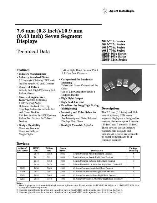
Features• Industry Standard Size • Industry Standard Pinout7.62 mm (0.300 inch) DIP Leads on 2.54 mm (0.100 inch) Centers • Choice of ColorsAlGaAs Red, High Efficiency Red,Yellow, Green• Excellent Appearance Evenly Lighted Segments ±50° Viewing AngleOptimum Contrast Given byGray Top Surface for AlGaAs Red and Green DevicesRed Top Surface for HER Devices Yellow Top Surface for Yellow Devices• Design Flexibility Common Anode or Common Cathode Single DigitsLeft or Right Hand Decimal Point ±1. Overflow Character• Categorized for Luminous IntensityYellow and Green Categorized for ColorUse of Like Categories Yields a Uniform Display • High Light Output • High Peak Current• Excellent for Long Digit String Multiplexing• Intensity and Color Selection AvailableSee Intensity and Color Selected Displays Data Sheet• Sunlight Viewable AlGaAsAlGaAs [1]HER [1]Yellow Green Package Red HDSP-5082-5082-HDSP-DescriptionDrawing7610762036007.6 mm Common Anode Left Hand Decimal A 7611762136017.6 mm Common Anode Right Hand Decimal B 7613762336037.6 mm Common Cathode Right Hand Decimal C 7616762636067.6 mm Universal ±1. Overflow Right Hand Decimal [2]D E15076507660460010.9 mm Common Anode Left Hand Decimal E E15176517661460110.9 mm Common Anode Right Hand Decimal F E15376537663460310.9 mm Common Cathode Right Hand Decimal G E15676567666460610.9 mm Universal ±1. Overflow Right Hand Decimal [2]HNotes:1. These displays are recommended for high ambient light operation. Please refer to the HDSP-E10X AlGaAs and HDSP-335X HER data sheet for low current operation.2. Universal pinout brings the anode and cathode of each segment’s LED out to separate pins. See internal diagram D.3. Universal pinout brings the anode and cathode of each segment’s LED out to separate pins. See internal diagram H.Devices5082-761x Series 5082-762x Series 5082-765x Series 5082-766x Series HDSP-360x Series HDSP-460x Series HDSP-E15x Series7.6 mm (0.3 inch)/10.9 mm (0.43 inch) Seven Segment Displays Technical DataDescriptionThe 7.6 mm (0.3 inch) and 10.9mm (0.43 inch) LED sevensegment displays are designed for viewing distances up to 3 metres (10 feet) and 5 metres (16 feet).These devices use an industry standard size package andpinouts. All devices are available as either common anode or common cathode.Part Numbering System5082 -X X X X-X X X X XHDSP-X X X X-X X X X XMechanical Options[1]00: No Mechanical OptionColor Bin Options[1,2]0: No Color Bin Limitation4: Color Bin 4 Only (applicable for Green devices only)B: Color Bins 2 and 3 (applicable for Yellow devices only)Maximum Intensity Bin[1,2]0: No Maximum Intensity Bin LimitationMinimum Intensity Bin[1,2]0: No Minimum Intensity Bin LimitationDevice Configuration/Color[1]0: Common Anode1: Common Anode3: Common CathodeDevice Specific Configuration[1]Refer to Respective DatasheetPackage[1]E: 10.9 mm (0.43 inch) Single Digit Seven Segment Display Notes:1. For codes not listed in the figure above, please refer to the respective datasheet or contact your nearestAgilent representative for details.2. Bin options refer to shippable bins for a part number. Color and Intensity Bins are typically restricted to 1bin per tube (exceptions may apply). Please refer to respective datasheet for specific bin limit information.displays are ideal for portable applications. The high light ambient displays are ideal for high light ambients or long string lengths. For additional informa-tion see the Low Current Seven Segment Displays, or High Light Ambient Seven Segment Displays data sheets.NOTES;1. DIMENSIONS IN MILLIMETRES AND (INCHES).2. ALL UNTOLERANCED DIMENSIONS ARE FOR REFERENCE ONLY.3. REDUNDANT ANODES.4. UNUSED DP POSITION.5. SEE INTERNALCIRCUIT DIAGRAM.6. REDUNDANT CATHODE.7. SEE PART NUMBER TABLE FOR L.H.D.P.AND R.H.D.P.DESIGNATION.8. FOR YELLOW AND GREEN DEVICES ONLY.Package DimensionsThese displays are ideal for most applications. Pin for pin equiva-lent displays are also available in a low current or high lightambient design. The low currentInternal Circuit DiagramAbsolute Maximum RatingsAlGaAs Red HER Yellow GreenHDSP-E1505082-7610/5082-7620/HDSP-3600/ Description Series7650 Series7660 Series4600 Series Units Average Power per Segment or DP9610580105mW Peak Forward Current per160[1]90[3]60[5]90[7]mA Segment or DPDC Forward Current per40[2]30[4]20[6]30[8]mA Segment or DPOperating Temperature Range-20 to +100[9]-40 to +100°C Storage Temperature Range -55 to +100°C Reverse Voltage per 3.0V Segment or DPWave Soldering Temperature for3 Seconds (1.59 mm [0.063 in.] 250°Cbelow Body)Notes:1.See Figure 1 to establish pulsed conditions.2. Derate above 46°C at 0.54 mA/°C.3. See Figure 6 to establish pulsed conditions.4. Derate above 53°C at 0.45 mA/°C.5. See Figure 7 to establish pulsed conditions.6. Derate above 81°C at 0.52 mA/°C.7. See Figure 8 to establish pulsed conditions.8. Derate above 39°C at 0.37 mA/°C.9. For operation below -20°C, contact your local Agilent components sales office or an authorized distributor.Electrical/Optical Characteristics at T A = 25°CAlGaAs RedDeviceSeries Parameter Symbol Min.Typ.Max.Units Test Conditions Luminous Intensity/Segment[1,2,5]I V8.515.0mcd I F = 20 mA(Digit Average)1.8V I F = 20 mAForward Voltage/Segment or DP V F2.03.0V I F = 100 mAHDSP-E15x Peak WavelengthλPEAK645nmDominant Wavelength[3]λd637nmReverse Voltage/Segment or DP[4]V R 3.015V I R = 100 µATemperature Coefficient of∆V F/°C-2mV/°CV F/Segment or DPThermal Resistance LED Junction-RθJ-PIN340°C/W/Segto-PinHigh Efficiency RedDeviceSeries Parameter Symbol Min.Typ.Max.Units Test Conditions 5082-761x Luminous Intensity/Segment[1,2,6]340800µcd I F = 5 mA (Digit Average)I V5082-765x3401115µcd I F = 5 mA Forward Voltage/Segment or DP V F 2.1 2.5V I F = 20 mAPeak WavelengthλPEAK635nmDominant Wavelength[3]λd626nm AllReverse Voltage/Segment or DP[4]V R 3.030V I R = 100 µATemperature Coefficient of∆V F/°C-2mV/°CV F/Segment or DPThermal Resistance LED RθJ-PIN280°C/WJunction-to-PinDevice Series ParameterSymbol Min.Typ.Max.Units Test Conditions 5082-762x Luminous Intensity/Segment [1,2]205620µcdI F = 5 mA(Digit Average)I V5082-766x290835µcd I F = 5 mA Forward Voltage/Segment or DP V F 2.2 2.5V I F = 20 mAPeak WavelengthλPEAK 583nm Dominant Wavelength [3,7]λd 581.5586592.5nm AllReverse Voltage/Segment or DP [4]V R 3.040V I R = 100 µA Temperature Coefficient of ∆V F /°C -2mV/°C V F /Segment or DP Thermal Resistance LED R θJ-PIN280°C/W/SegJunction-to-PinYellowNotes:1. Device case temperature is 25°C prior to the intensity measurement.2. The digits are categorized for luminous intensity. The intensity category is designated by a letter on the side of the package.3. The dominant wavelength, λd , is derived from the CIE chromaticity diagram and is that single wavelength which defines the color of the device.4. Typical specification for reference only. Do not exceed absolute maximum ratings.5. For low current operation, the AlGaAs HDSP-E10X series displays are recommended. They are tested at 1 mA dc/segment and are pin for pin compatible with the HDSP-E15X series.6. For low current operation, the HER HDSP-335X series displays are recommended. They are tested at 2 mA dc/segment and are pin for pin compatible with the 5082-7650 series.7. The Yellow (5082-7620/7660) and Green (HDSP-3600/4600) displays are categorized for dominant wavelength. The category is designated by a number adjacent to the luminous intensity category letter.High Performance GreenDevice Test Series ParameterSymbol Min.Typ.Max.Units Conditions HDSP-360x Luminous Intensity/Segment [1,2]8602700µcdI F = 10 mA(Digit Average)I VHDSP-460x10304000µcd I F = 10 mA Forward Voltage/Segment or DP V F 2.1 2.5V I F = 10 mAPeak WavelengthλPEAK 566nm Dominant Wavelength [3,7]λd 571577nm AllReverse Voltage/Segment or DP [4]V R 3.050V I R = 100 µA Temperature Coefficient of ∆V F /°C -2mV/°C V F /Segment or DP Thermal Resistance LED R θJ -PIN280°C/W/SegJunction-to-PinFigure 3. Forward Current vs. Forward Voltage.Figure 2. Maximum Allowable DC Current vs.Ambient Temperature.Figure 4. Relative Luminous Intensity vs. DC Forward Current.Figure 5. Relative Efficiency (Luminous Intensity per Unit Current) vs. Peak Current.AlGaAs RedI D C M A X . – M A X I M U M D C C U R R E N T P E R S E G M E N T – m AT A – AMBIENT TEMPERATURE – °C5030102051525354045I F – F O R W A R D C U R R E N T P E R S E G M E N T – m AV F – FORWARD VOLTAGE – V R E L A T I V E L U M I N O U S I N T E N S I T Y (N O R M A L I Z E D T O 1 A T 20 m A )0I F – FORWARD CURRENT PER SEGMENT – mA2.001.501.250.750.2520401.751.000.5010305152535ηP E A K – N O R M A L I Z E D R E L A T I V E EF F I C I E N C Y0.5I PEAK – PEAK FORWARD CURRENTPER SEGMENT – mA50.0150.05.0HER, Yellow, GreenFigure 8. Allowable Peak Current vs.Pulse Duration – Green Series.Figure 9. Maximum Allowable DC Current vs.Ambient Temperature.Figure 11. Relative LuminousIntensity vs. DC Forward Current.Figure 10. Forward Current vs.Forward Voltage.Figure 12. Relative LuminousEfficiency (Luminous Intensity per Unit Current) vs. Peak Current.HDSP-E15x IV Bin Category Min.Max.L 8.6715.90M 13.0023.80N 19.5035.80O 29.3053.60P 43.9080.50Intensity Bin Limits (mcd)AlGaAs RedHER5082-761x IV Bin Category Min.Max.B 0.3690.630C 0.5160.946D 0.774 1.418E 1.160 2.127F 1.740 3.190G 2.610 4.785H 3.9157.1775082-765xIV Bin Category Min.Max.B 0.3470.593C 0.4850.890D 0.728 1.333E 1.091 2.000F 1.636 3.000G 2.454 4.500H 3.6826.751Yellow5082-762x IV Bin Category Min.Max.B 0.2290.387C 0.3170.582D 0.4760.872E 0.714 1.311F 1.073 1.967G 1.609 2.950H 2.413 4.4255082-766xIV Bin Category Min.Max.C 0.2970.543D 0.4450.817E 0.669 1.225F 1.003 1.838G 1.504 2.758H 2.2564.137HDSP-460xIV Bin Category Min.Max.G 1.03 1.88H 1.54 2.82I 2.31 4.23J 3.46 6.34K 5.189.50L 7.7814.26GreenHDSP-360x IV Bin Category Min.Max.H 0.86 1.58I 1.29 2.37J 1.94 3.55K 2.90 5.33L 4.378.01Color CategoriesNote:All categories are established for classification of products. Products may not be available in all categories. Please contact your Agilent representatives for further clarification/information.Contrast EnhancementFor information on contrastenhancement, please seeApplication Note 1015.Soldering/CleaningFor information on solderingLEDs, please refer to ApplicationNote 1027.元器件交易网/semiconductorsFor product information and a complete list ofdistributors, please go to our web site.For technical assistance call:Americas/Canada: +1 (800) 235-0312 or(916) 788-6763Europe: +49 (0) 6441 92460China: 10800 650 0017Hong Kong: (+65) 6756 2394India, Australia, New Zealand: (+65) 6755 1939Japan: (+81 3) 3335-8152 (Domestic/Interna-tional), or 0120-61-1280 (Domestic Only)Korea: (+65) 6755 1989Singapore, Malaysia, Vietnam, Thailand,Philippines, Indonesia: (+65) 6755 2044Taiwan: (+65) 6755 1843Data subject to change.Copyright © 2004 Agilent Technologies, Inc.Obsoletes 5963-7394EJuly 17, 20045988-3325EN。
米顿罗计量泵技术说明

maxRoy 系列
马达驱动液压隔膜计量泵 手动,电动,调频控制 最大流量 :1,091 L/H 最高压力 :10 Bar
2
Milroyal 系列
马达驱动液压隔膜计量泵 手动,电动,调频,气动控制 单头最大流量 :8,150 L/H 最高压力 :690 Bar
Primeroyal 系列
马达驱动液压隔膜计量泵 手动,电动 , 调频,气动控制 单头最大流量 :15,882 L/H 最高压力 :615 Bar
PE.375”O.D.
1/4”NPT M
PE.250”O.D.
1/4”NPT M
PE.375”O.D.
1/4”NPT M
进、出口连接
316SS 1/4”NPT M 1/4”NPT M 1/4”NPT M
A1 系列手动调节电磁泵 流量 :22 L/hr 压力 :17.3 Bar
A146 ---- 350TI
7- 接受外部脉冲信号自动调节冲程长度和速度 ; 9- 接受外部 4-20mA 信号自动调节冲程长度和速度
* 转换到外部控制方式时 , 最小输出流量为零
出口压力 Bar
10.3 6.9 3.5 2.1
进、出口连接
Acrylic/PVC/PVDF
316SS
PE.375”O.D.
1/4”NPT M
PE.375”O.D.
高精度单向止回阀系统 ---- 保证计量泵的恒定高精度
米顿罗公司计量泵的出、入口分别装有高精度的单向止回阀,阀体具有独特的导向设计。
3
隔膜检漏报警技术 ---- 保证 输送危险性物料过程的安全
米 顿 罗 公 司 采 用 双 隔 膜 技 术 及“ 三 明 治”式三隔膜技术,使偶然发生的隔膜 破损情况能被迅速检测,并给出报警信 号,从而避免危险性物料的可能泄漏。
HDSP中文资料

Features• Low Power Consumption • Industry Standard Size• Industry Standard Pinout • Choice of Character Size7.6 mm (0.30 in), 10 mm (0.40 in), 10.9 mm (0.43 in), 14.2 mm (0.56 in), 20 mm (0.80 in)• Choice of ColorsAlGaAs Red, High Efficiency Red (HER), Yellow, Green• Excellent Appearance Evenly Lighted Segments±50° Viewing Angle• Design FlexibilityCommon Anode or Common CathodeSingle and Dual DigitLeft and Right Hand Decimal Points±1. Overflow Character• Categorized for Luminous IntensityYellow and Green Categorized for ColorUse of Like Categories Yields a Uniform Display• Excellent for Long Digit String Multiplexing DescriptionThese low current seven segment displays are designed for applica-tions requiring low power consumption. They are tested and selected for their excellent low current characteristics to ensure that the segments are matched at low currents. Drive currents as low as 1 mA per segment are available.Pin for pin equivalent displays are also available in a standard current or high light ambient design. The standard current displays are available in all colors and are ideal for most applica-tions. The high light ambient displays are ideal for sunlight ambients or long string lengths. For additional information see the 7.6 mm Micro Bright Seven Segment Displays, 10 mm Seven Segment Displays, 7.6 mm/10.9 mm Seven Segment Displays, 14.2 mm Seven Segment Displays, 20 mm Seven Segment Displays, or High Light Ambient Seven Segment Displays data sheets.Low Current Seven SegmentDisplays Technical Data HDSP-335x SeriesHDSP-555x SeriesHDSP-751x SeriesHDSP-A10x Series HDSP-A80x Series HDSP-A90x Series HDSP-E10x Series HDSP-F10x Series HDSP-G10x Series HDSP-H10x Series HDSP-K12x, K70x Series HDSP-N10x SeriesHDSP-N40x SeriesDevicesAlGaAs HER Yellow Green Package HDSP-HDSP-HDSP-HDSP-Description Drawing A1017511A801A9017.6 mm Common Anode Right Hand Decimal A A1037513A803A9037.6 mm Common Cathode Right Hand Decimal B A1077517A807A9077.6 mm Common Anode ±1. Overflow C A1087518A808A9087.6 mm Common Cathode ±1. Overflow D F10110 mm Common Anode Right Hand Decimal E F10310 mm Common Cathode Right Hand Decimal F F10710 mm Common Anode ±1. Overflow G F10810 mm Common Cathode ±1. Overflow H G10110 mm Two Digit Common Anode Right Hand Decimal X G10310 mm Two Digit Common Cathode Right Hand Decimal Y E100335010.9 mm Common Anode Left Hand Decimal I E101335110.9 mm Common Anode Right Hand Decimal J E103335310.9 mm Common Cathode Right Hand Decimal K E106335610.9 mm Universal ±1. Overflow[1]L H101555114.2 mm Common Anode Right Hand Decimal M H103555314.2 mm Common Cathode Right Hand Decimal N H107555714.2 mm Common Anode ±1. Overflow O H108555814.2 mm Common Cathode ±1. Overflow P K121K70114.2 mm Two Digit Common Anode Right Hand Decimal R K123K70314.2 mm Two Digit Common Cathode Right Hand Decimal S N10020 mm Common Anode Left Hand Decimal Q N101N40120 mm Common Anode Right Hand Decimal T N103N40320 mm Common Cathode Right Hand Decimal U N10520 mm Common Cathode Left Hand Decimal V N106N40620 mm Universal ±1. Overflow[1]W Note:1. Universal pinout brings the anode and cathode of each segment’s LED out to separate pins. See internal diagrams L or W.Part Numbering System5082-x xx x-x x x xxHDSP-x xx x-x x x xxMechanical Options[1]00: No mechanical optionColor Bin Options[1,2]0: No color bin limitationMaximum Intensity Bin[1,2]0: No maximum intensity bin limitationMinimum Intensity Bin[1,2]0: No minimum intensity bin limitationDevice Configuration/Color[1]G: GreenDevice Specific Configuration[1]Refer to respective datasheetPackage[1]Refer to Respective datasheetNotes:1. For codes not listed in the figure above, please refer to the respective datasheet or contact your nearest Agilent representative fordetails.2. Bin options refer to shippable bins for a part-number. Color and Intensity Bins are typically restricted to 1 bin per tube (excep-tions may apply). Please refer to respective datasheet for specific bin limit information.Package DimensionsPackage Dimensions (cont.)Package Dimensions (cont.)*The Side View of package indicates Country of Origin.Package Dimensions (cont.)Package Dimensions (cont.)Package Dimensions (cont.)Internal Circuit DiagramInternal Circuit Diagram (cont.)Absolute Maximum RatingsAlGaAs Red - HDSP-HERA10X/E10X/H10X HDSP-751X/Yellow GreenK12X/N10X/N40X335X/555X/HDSP-A80X HDSP-A90X Description F10X, G10X Series K70X Series Series Series Units Average Power per Segment or DP375264mW Peak Forward Current per 45mA Segment or DPDC Forward Current per15[1]15[2]mA Segment or DPOperating Temperature Range-20 to +100-40 to +100°C Storage Temperature Range -55 to +100°C Reverse Voltage per Segment 3.0V or DPWave Soldering Temperature for 3Seconds (1.60 mm [0.063 in.] below 250°C seating body)Notes:1. Derate above 91°C at 0.53 mA/°C.2. Derate HER/Yellow above 80°C at 0.38 mA/°C and Green above 71°C at 0.31 mA/°C.Electrical/Optical Characteristics at T A = 25°CAlGaAs RedDeviceSeriesHDSP-Parameter Symbol Min.Typ.Max.Units Test Conditions315600I F = 1 mA A10x3600I F = 5 mA330650I F = 1 mAF10x, G10x3900I F = 5 mA390650I F = 1 mA E10x Luminous Intensity/Segment[1,2]I Vµcd(Digit Average)3900I F = 5 mA400700I F = 1 mAH10x, K12x4200I F = 5 mA270590I F = 1 mAN10x, N40x3500I F = 5 mA1.6I F = 1 mAForward Voltage/Segment or DP V F 1.7V I F = 5 mA1.82.2I F = 20 mA PkAll Devices Peak WavelengthλPEAK645nmDominant Wavelength[3]λd637nmReverse Voltage/Segment or DP[4]V R 3.015V I R = 100 µATemperature Coefficient of∆V F/°C-2 mV mV/°CV F/Segment or DPA10x255F10x, G10x320E10x340Thermal Resistance LED RθJ-PIN°C/W/SegH10x, K12x Junction-to-Pin400N10x, N40x430High Efficiency RedDeviceSeriesHDSP-Parameter Symbol Min.Typ.Max.Units Test Conditions160270I F = 2 mA 751x1050I F = 5 mA200300I F = 2 mA Luminous Intensity/Segment[1,2]I V mcd(Digit Average)1200I F = 5 mA335x, 555x,K70x270370I F = 2 mA1480I F = 5 mA1.6I F = 2 mAForward Voltage/Segment or DP V F 1.7V I F = 5 mA2.1 2.5I F = 20 mA Pk All Devices Peak WavelengthλPEAK635nmDominant Wavelength[3]λd626nmReverse Voltage/Segment or DP[4]V R 3.030V I R = 100 µATemperature Coefficient of∆V F/°C-2mV/°CV F/Segment or DP751x200335x Thermal Resistance LED RθJ-PIN280°C/WJunction-to-Pin555x, K70x345YellowDeviceSeriesHDSP-Parameter Symbol Min.Typ.Max.Units Test Conditions Luminous Intensity/Segment[1,2]250420I F = 4 mA(Digit Average)I V mcd1300I F = 10 mA1.7I F = 4 mAForward Voltage/Segment or DP V F 1.8V I F = 5 mA A80x2.1 2.5I F = 20 mA PkPeak WavelengthλPEAK583nmDominant Wavelength[3,5]λd581.5585592.5nmReverse Voltage/Segment or DP[4]V R 3.030V I R = 100 µATemperature Coefficient of∆V F/°C-2mV/°CV F/Segment or DPThermal Resistance LED RθJ-PIN200°C/WJunction-to-PinGreenDeviceSeriesHDSP-Parameter Symbol Min.Typ.Max.Units Test Conditions Luminous Intensity/Segment[1,2]250475I F = 4 mA(Digit Average)I V mcd1500I F = 10 mA1.9I F = 4 mAForward Voltage/Segment or DP V F 2.0V I F = 10 mA A90x2.1 2.5I F = 20 mA PkPeak WavelengthλPEAK566nmDominant Wavelength[3,5]λd571577nmReverse Voltage/Segment or DP[4]V R 3.030V I R = 100 µATemperature Coefficient of∆V F/°C-2mV/°CV F/Segment or DPThermal Resistance LED RθJ-PIN200°C/WJunction-to-PinNotes:1. Device case temperature is 25°C prior to the intensity measurement.2. The digits are categorized for luminous intensity. The intensity category is designated by a letter on the side of the package.3. The dominant wavelength, λd, is derived from the CIE chromaticity diagram and is the single wavelength which defines the color of thedevice.4. Typical specification for reference only. Do not exceed absolute maximum ratings.5. The yellow (HDSP-A800) and Green (HDSP-A900) displays are categorized for dominant wavelength. The category is designated by anumber adjacent to the luminous intensity category letter.AlGaAs RedIntensity Bin Limits (mcd)AlGaAs RedHDSP-A10xIV Bin Category Min.Max.E0.3150.520F0.4280.759G0.621 1.16H0.945 1.71I 1.40 2.56J 2.10 3.84K 3.14 5.75L 4.708.55HDSP-E10x/F10x/G10xIV Bin Category Min.Max.D0.3910.650E0.5320.923F0.755 1.39G 1.13 2.08H 1.70 3.14HDSP-H10x/K12xIV Bin Category Min.Max.C0.4150.690D0.5650.990E0.810 1.50F 1.20 2.20G 1.80 3.30H 2.73 5.00I 4.097.50HDSP-N10xIV Bin Category Min.Max.A0.2700.400B0.3250.500C0.4150.690D0.5650.990E0.810 1.50F 1.20 2.20G 1.80 3.30H 2.73 5.00I 4.097.50Intensity Bin Limits (mcd), continued HERHDSP-751xIV Bin Category Min.Max.B0.1600.240C0.2000.300D0.2500.385E0.3150.520F0.4280.759G0.621 1.16HDSP-751xIV Bin Category Min.Max.B0.2400.366C0.3000.477D0.3910.650E0.5320.923F0.755 1.39G 1.13 2.08H 1.70 3.14HDSP-555x/K70xIV Bin Category Min.Max.A0.2700.400B0.3250.500C0.4150.690D0.5650.990E0.810 1.50F 1.20 2.20G 1.80 3.30H 2.73 5.00I 4.097.50Intensity Bin Limits (mcd), continued YellowHDSP-A80xIV Bin Category Min.Max.D0.2500.385E0.3150.520F0.4250.760G0.625 1.14H0.940 1.70I 1.40 2.56J 2.10 3.84K 3.14 5.76L 4.718.64M7.0713.00N10.6019.40O15.9029.20P23.9043.80Q35.8065.60GreenHDSP-A90xIV Bin Category Min.Max.E0.3150.520F0.4250.760G0.625 1.14H0.940 1.70I 1.40 2.56J 2.10 3.84K 3.14 5.76L 4.718.64M7.0713.00N10.6019.40O15.9029.20P23.9043.80Q35.8065.60Electrical/OpticalFor more information on electrical/optical characteristics, please see Application Note 1005.Contrast Enhancement For information on contrast enhancement, please see Application Note 1015.Soldering/Cleaning Cleaning agents from the ketone family (acetone, methyl ethyl ketone, etc.) and from the chorinated hydrocarbon family (methylene chloride, trichloro-ethylene, carbon tetrachloride, etc.) are not recommended for cleaning LED parts. All of these various solvents attack or dissolve the encapsulating epoxies used to form the package of plastic LED parts.For information on soldering LEDs, please refer to Application Note 1027.Note:All categories are established for classification of products. Productsmay not be available in all categories. Please contact your localAgilent representatives for further clarification/information.Color Categories/semiconductorsFor product information and a complete list ofdistributors, please go to our web site.For technical assistance call:Americas/Canada: +1 (800) 235-0312 or(916) 788 6763Europe: +49 (0) 6441 92460China: 10800 650 0017Hong Kong: (+65) 6271 2451India, Australia, New Zealand: (+65) 6271 2394Japan: (+81 3) 3335-8152(Domestic/International), or0120-61-1280(Domestic Only)Korea: (+65) 6271 2194Malaysia, Singapore: (+65) 6271 2054Taiwan: (+65) 6271 2654Data subject to change.Copyright © 2005 Agilent Technologies, Inc.Obsoletes 5988-8412ENJanuary 19, 20055989-0080EN。
5082-A808-MO000中文资料

Features• Low Power Consumption • Industry Standard Size• Industry Standard Pinout • Choice of Character Size7.6 mm (0.30 in), 10 mm (0.40 in), 10.9 mm (0.43 in), 14.2 mm (0.56 in), 20 mm (0.80 in)• Choice of ColorsAlGaAs Red, High Efficiency Red (HER), Yellow, Green• Excellent Appearance Evenly Lighted Segments±50° Viewing Angle• Design FlexibilityCommon Anode or Common CathodeSingle and Dual DigitLeft and Right Hand Decimal Points±1. Overflow Character• Categorized for Luminous IntensityYellow and Green Categorized for ColorUse of Like Categories Yields a Uniform Display• Excellent for Long Digit String Multiplexing DescriptionThese low current seven segment displays are designed for applica-tions requiring low power consumption. They are tested and selected for their excellent low current characteristics to ensure that the segments are matched at low currents. Drive currents as low as 1 mA per segment are available.Pin for pin equivalent displays are also available in a standard current or high light ambient design. The standard current displays are available in all colors and are ideal for most applica-tions. The high light ambient displays are ideal for sunlight ambients or long string lengths. For additional information see the 7.6 mm Micro Bright Seven Segment Displays, 10 mm Seven Segment Displays, 7.6 mm/10.9 mm Seven Segment Displays, 14.2 mm Seven Segment Displays, 20 mm Seven Segment Displays, or High Light Ambient Seven Segment Displays data sheets.Low Current Seven SegmentDisplays Technical Data HDSP-335x SeriesHDSP-555x SeriesHDSP-751x SeriesHDSP-A10x Series HDSP-A80x Series HDSP-A90x Series HDSP-E10x Series HDSP-F10x Series HDSP-G10x Series HDSP-H10x Series HDSP-K12x, K70x Series HDSP-N10x SeriesHDSP-N40x SeriesDevicesAlGaAs HER Yellow Green Package HDSP-HDSP-HDSP-HDSP-Description Drawing A1017511A801A9017.6 mm Common Anode Right Hand Decimal A A1037513A803A9037.6 mm Common Cathode Right Hand Decimal B A1077517A807A9077.6 mm Common Anode ±1. Overflow C A1087518A808A9087.6 mm Common Cathode ±1. Overflow D F10110 mm Common Anode Right Hand Decimal E F10310 mm Common Cathode Right Hand Decimal F F10710 mm Common Anode ±1. Overflow G F10810 mm Common Cathode ±1. Overflow H G10110 mm Two Digit Common Anode Right Hand Decimal X G10310 mm Two Digit Common Cathode Right Hand Decimal Y E100335010.9 mm Common Anode Left Hand Decimal I E101335110.9 mm Common Anode Right Hand Decimal J E103335310.9 mm Common Cathode Right Hand Decimal K E106335610.9 mm Universal ±1. Overflow[1]L H101555114.2 mm Common Anode Right Hand Decimal M H103555314.2 mm Common Cathode Right Hand Decimal N H107555714.2 mm Common Anode ±1. Overflow O H108555814.2 mm Common Cathode ±1. Overflow P K121K70114.2 mm Two Digit Common Anode Right Hand Decimal R K123K70314.2 mm Two Digit Common Cathode Right Hand Decimal S N10020 mm Common Anode Left Hand Decimal Q N101N40120 mm Common Anode Right Hand Decimal T N103N40320 mm Common Cathode Right Hand Decimal U N10520 mm Common Cathode Left Hand Decimal V N106N40620 mm Universal ±1. Overflow[1]W Note:1. Universal pinout brings the anode and cathode of each segment’s LED out to separate pins. See internal diagrams L or W.Part Numbering System5082-x xx x-x x x xxHDSP-x xx x-x x x xxMechanical Options[1]00: No mechanical optionColor Bin Options[1,2]0: No color bin limitationMaximum Intensity Bin[1,2]0: No maximum intensity bin limitationMinimum Intensity Bin[1,2]0: No minimum intensity bin limitationDevice Configuration/Color[1]G: GreenDevice Specific Configuration[1]Refer to respective datasheetPackage[1]Refer to Respective datasheetNotes:1. For codes not listed in the figure above, please refer to the respective datasheet or contact your nearest Agilent representative fordetails.2. Bin options refer to shippable bins for a part-number. Color and Intensity Bins are typically restricted to 1 bin per tube (excep-tions may apply). Please refer to respective datasheet for specific bin limit information.Package DimensionsPackage Dimensions (cont.)Package Dimensions (cont.)*The Side View of package indicates Country of Origin.Package Dimensions (cont.)Package Dimensions (cont.)Package Dimensions (cont.)Internal Circuit DiagramInternal Circuit Diagram (cont.)Absolute Maximum RatingsAlGaAs Red - HDSP-HERA10X/E10X/H10X HDSP-751X/Yellow GreenK12X/N10X/N40X335X/555X/HDSP-A80X HDSP-A90X Description F10X, G10X Series K70X Series Series Series Units Average Power per Segment or DP375264mW Peak Forward Current per 45mA Segment or DPDC Forward Current per15[1]15[2]mA Segment or DPOperating Temperature Range-20 to +100-40 to +100°C Storage Temperature Range -55 to +100°C Reverse Voltage per Segment 3.0V or DPWave Soldering Temperature for 3Seconds (1.60 mm [0.063 in.] below 250°C seating body)Notes:1. Derate above 91°C at 0.53 mA/°C.2. Derate HER/Yellow above 80°C at 0.38 mA/°C and Green above 71°C at 0.31 mA/°C.Electrical/Optical Characteristics at T A = 25°CAlGaAs RedDeviceSeriesHDSP-Parameter Symbol Min.Typ.Max.Units Test Conditions315600I F = 1 mA A10x3600I F = 5 mA330650I F = 1 mAF10x, G10x3900I F = 5 mA390650I F = 1 mA E10x Luminous Intensity/Segment[1,2]I Vµcd(Digit Average)3900I F = 5 mA400700I F = 1 mAH10x, K12x4200I F = 5 mA270590I F = 1 mAN10x, N40x3500I F = 5 mA1.6I F = 1 mAForward Voltage/Segment or DP V F 1.7V I F = 5 mA1.82.2I F = 20 mA PkAll Devices Peak WavelengthλPEAK645nmDominant Wavelength[3]λd637nmReverse Voltage/Segment or DP[4]V R 3.015V I R = 100 µATemperature Coefficient of∆V F/°C-2 mV mV/°CV F/Segment or DPA10x255F10x, G10x320E10x340Thermal Resistance LED RθJ-PIN°C/W/SegH10x, K12x Junction-to-Pin400N10x, N40x430High Efficiency RedDeviceSeriesHDSP-Parameter Symbol Min.Typ.Max.Units Test Conditions160270I F = 2 mA 751x1050I F = 5 mA200300I F = 2 mA Luminous Intensity/Segment[1,2]I V mcd(Digit Average)1200I F = 5 mA335x, 555x,K70x270370I F = 2 mA1480I F = 5 mA1.6I F = 2 mAForward Voltage/Segment or DP V F 1.7V I F = 5 mA2.1 2.5I F = 20 mA Pk All Devices Peak WavelengthλPEAK635nmDominant Wavelength[3]λd626nmReverse Voltage/Segment or DP[4]V R 3.030V I R = 100 µATemperature Coefficient of∆V F/°C-2mV/°CV F/Segment or DP751x200335x Thermal Resistance LED RθJ-PIN280°C/WJunction-to-Pin555x, K70x345YellowDeviceSeriesHDSP-Parameter Symbol Min.Typ.Max.Units Test Conditions Luminous Intensity/Segment[1,2]250420I F = 4 mA(Digit Average)I V mcd1300I F = 10 mA1.7I F = 4 mAForward Voltage/Segment or DP V F 1.8V I F = 5 mA A80x2.1 2.5I F = 20 mA PkPeak WavelengthλPEAK583nmDominant Wavelength[3,5]λd581.5585592.5nmReverse Voltage/Segment or DP[4]V R 3.030V I R = 100 µATemperature Coefficient of∆V F/°C-2mV/°CV F/Segment or DPThermal Resistance LED RθJ-PIN200°C/WJunction-to-PinGreenDeviceSeriesHDSP-Parameter Symbol Min.Typ.Max.Units Test Conditions Luminous Intensity/Segment[1,2]250475I F = 4 mA(Digit Average)I V mcd1500I F = 10 mA1.9I F = 4 mAForward Voltage/Segment or DP V F 2.0V I F = 10 mA A90x2.1 2.5I F = 20 mA PkPeak WavelengthλPEAK566nmDominant Wavelength[3,5]λd571577nmReverse Voltage/Segment or DP[4]V R 3.030V I R = 100 µATemperature Coefficient of∆V F/°C-2mV/°CV F/Segment or DPThermal Resistance LED RθJ-PIN200°C/WJunction-to-PinNotes:1. Device case temperature is 25°C prior to the intensity measurement.2. The digits are categorized for luminous intensity. The intensity category is designated by a letter on the side of the package.3. The dominant wavelength, λd, is derived from the CIE chromaticity diagram and is the single wavelength which defines the color of thedevice.4. Typical specification for reference only. Do not exceed absolute maximum ratings.5. The yellow (HDSP-A800) and Green (HDSP-A900) displays are categorized for dominant wavelength. The category is designated by anumber adjacent to the luminous intensity category letter.AlGaAs RedIntensity Bin Limits (mcd)AlGaAs RedHDSP-A10xIV Bin Category Min.Max.E0.3150.520F0.4280.759G0.621 1.16H0.945 1.71I 1.40 2.56J 2.10 3.84K 3.14 5.75L 4.708.55HDSP-E10x/F10x/G10xIV Bin Category Min.Max.D0.3910.650E0.5320.923F0.755 1.39G 1.13 2.08H 1.70 3.14HDSP-H10x/K12xIV Bin Category Min.Max.C0.4150.690D0.5650.990E0.810 1.50F 1.20 2.20G 1.80 3.30H 2.73 5.00I 4.097.50HDSP-N10xIV Bin Category Min.Max.A0.2700.400B0.3250.500C0.4150.690D0.5650.990E0.810 1.50F 1.20 2.20G 1.80 3.30H 2.73 5.00I 4.097.50Intensity Bin Limits (mcd), continued HERHDSP-751xIV Bin Category Min.Max.B0.1600.240C0.2000.300D0.2500.385E0.3150.520F0.4280.759G0.621 1.16HDSP-751xIV Bin Category Min.Max.B0.2400.366C0.3000.477D0.3910.650E0.5320.923F0.755 1.39G 1.13 2.08H 1.70 3.14HDSP-555x/K70xIV Bin Category Min.Max.A0.2700.400B0.3250.500C0.4150.690D0.5650.990E0.810 1.50F 1.20 2.20G 1.80 3.30H 2.73 5.00I 4.097.50Intensity Bin Limits (mcd), continued YellowHDSP-A80xIV Bin Category Min.Max.D0.2500.385E0.3150.520F0.4250.760G0.625 1.14H0.940 1.70I 1.40 2.56J 2.10 3.84K 3.14 5.76L 4.718.64M7.0713.00N10.6019.40O15.9029.20P23.9043.80Q35.8065.60GreenHDSP-A90xIV Bin Category Min.Max.E0.3150.520F0.4250.760G0.625 1.14H0.940 1.70I 1.40 2.56J 2.10 3.84K 3.14 5.76L 4.718.64M7.0713.00N10.6019.40O15.9029.20P23.9043.80Q35.8065.60Electrical/OpticalFor more information on electrical/optical characteristics, please see Application Note 1005.Contrast Enhancement For information on contrast enhancement, please see Application Note 1015.Soldering/Cleaning Cleaning agents from the ketone family (acetone, methyl ethyl ketone, etc.) and from the chorinated hydrocarbon family (methylene chloride, trichloro-ethylene, carbon tetrachloride, etc.) are not recommended for cleaning LED parts. All of these various solvents attack or dissolve the encapsulating epoxies used to form the package of plastic LED parts.For information on soldering LEDs, please refer to Application Note 1027.Note:All categories are established for classification of products. Productsmay not be available in all categories. Please contact your localAgilent representatives for further clarification/information.Color Categories/semiconductorsFor product information and a complete list ofdistributors, please go to our web site.For technical assistance call:Americas/Canada: +1 (800) 235-0312 or(916) 788 6763Europe: +49 (0) 6441 92460China: 10800 650 0017Hong Kong: (+65) 6271 2451India, Australia, New Zealand: (+65) 6271 2394Japan: (+81 3) 3335-8152(Domestic/International), or0120-61-1280(Domestic Only)Korea: (+65) 6271 2194Malaysia, Singapore: (+65) 6271 2054Taiwan: (+65) 6271 2654Data subject to change.Copyright © 2005 Agilent Technologies, Inc.Obsoletes 5988-8412ENJanuary 19, 20055989-0080EN。
RYII中文资料
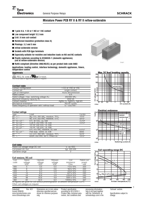
1Datasheet Rev. HC1 Issued 2008/03 Dimensions are in mm unlessotherwise specified and areshown for reference purposesProduct specificationaccording to IEC61810-1.Product data, technical para-processing informationonly to be used togetherwith the'Definitions' at‘Schrack’ section.Specifications subject toEspecially suitable for resistive and inductive loads on NO and NC contactsRoHS compliant (Directive 2002/95/EC) as per product date code 0403Applications: heating control, interface technology, domestic appliances, timers,V REG.-Nr. 5358, Z E214025Contact dataContact configuration 1 CO or 1NO or 1NCContact set single contactType of interruption micro disconnectionRated current8ARated voltage/max. switching voltage AC250/400VACMaximum breaking capacity AC2000VAContact material AgNi0,15, AgSnO2, AgCdOMechanical endurance30x106cyclesRated frequency of operation with/without load 6 / 1200min-1Contact ratingsType Load CyclesRY**1***NO, 8 A, 250 VAC, resistive, 70°C1x105RY**1***NC, 8 A, 250 VAC, resistive, 70°C5x104RY**(0,1,2)***8 A, 30 VDC, UL 5083x104RY**(0,1,2)***0,28 A, 250 VDC, UL 5083x104RY**(0,1,2)***1/2 HP, 240 VDC, UL 508RY**(0,1,2)***1/4 HP, 120 VDC, UL 508RY**(0)***8 A, 415 VAC, resistive, UL 5086x103RY**(0,1,2)***Pilot duty - B300, UL 5086000RY*** ***CO, 8 A, 250 VAC, resistive, 70°C5x103RY**1 ***6(4)A, 250 VAC, 85°C, EN607301x105Coil dataRated coil voltage range DC coil 5...60VDCCoil power DC coil typ. 220mWOperative range2Coil versions,DC-coilCoil Rated Operate Release Coil Rated coilcode voltage voltage voltage resistance powerVDC VDC VDC Ohm mW00553,50,5112+10%22300664,20,6162+10%22200996,30,9320+10%253012128,41,2627+10%2300242416,82,42350+10%2450484833,64,89391+10%2450606042,06,014000+10%257All figures are given for coil without preenergization, at ambient temperature +23°COther coil voltages on requestF0142-FInsulation CO contact NO contact Dielectric strength coil-contact circuit5000V effopen contact circuit1000V effClearance/creepage coil-contact circuit W8 / 8mmMaterial group of insulation parts IIIaTracking index of relay base PTI250, PTI 175* Type of insulation coil-contact circuit reinforcedopen contact circuit functionalRated insulation voltage250V250VPollution degree 3 23Rated voltage system230V 400V230 / 400VOvervoltage category III IIIOther dataRoHS - Directive 2002/95/EC compliant as per product date code 0403 Flammability class according to UL94V-0GWT to IEC 60335-1> 750 °C**Ambient temperature range -40...+70°CAmbient temperature max.85°C at 6AOperate- / release time typ. 7 / 3msBounce time NO / NC contact typ. 2.5 / 4.5ms Vibration resistance (function) NO/NC contact20 / 5gShock resistance (function) NO/NC contact20 / 5gShock resistance (destruction) 100gCategory of protection RTII-flux proof, RTIII- wash tight** Mounting pcbMounting position anyMinimum mounting distance W 0mmSoldering heat resistance flux proof version270°C/10swash tight version260°C/5sRelay weight8gPackaging unit20 / 500pcs AccessoiresFor technical details see datasheet Accessoires RYII* reflow-solderable version** not as reflow-solderable version PCB layout / terminal assignment Bottom view on solder pins1 NO, 1 NC contact 5mmS0254-AAS0254-ABS0254-ACS0254-ADS0254-AFS0254-AEDimensionsPinning 3.2mmPinning 5mmSoldering profile for reflow-solderable version。
5082-3350-CC000资料

Features• Low Power Consumption • Industry Standard Size• Industry Standard Pinout • Choice of Character Size7.6 mm (0.30 in), 10 mm (0.40 in), 10.9 mm (0.43 in), 14.2 mm (0.56 in), 20 mm (0.80 in)• Choice of ColorsAlGaAs Red, High Efficiency Red (HER), Yellow, Green• Excellent Appearance Evenly Lighted Segments±50° Viewing Angle• Design FlexibilityCommon Anode or Common CathodeSingle and Dual DigitLeft and Right Hand Decimal Points±1. Overflow Character• Categorized for Luminous IntensityYellow and Green Categorized for ColorUse of Like Categories Yields a Uniform Display• Excellent for Long Digit String Multiplexing DescriptionThese low current seven segment displays are designed for applica-tions requiring low power consumption. They are tested and selected for their excellent low current characteristics to ensure that the segments are matched at low currents. Drive currents as low as 1 mA per segment are available.Pin for pin equivalent displays are also available in a standard current or high light ambient design. The standard current displays are available in all colors and are ideal for most applica-tions. The high light ambient displays are ideal for sunlight ambients or long string lengths. For additional information see the 7.6 mm Micro Bright Seven Segment Displays, 10 mm Seven Segment Displays, 7.6 mm/10.9 mm Seven Segment Displays, 14.2 mm Seven Segment Displays, 20 mm Seven Segment Displays, or High Light Ambient Seven Segment Displays data sheets.Low Current Seven SegmentDisplays Technical Data HDSP-335x SeriesHDSP-555x SeriesHDSP-751x SeriesHDSP-A10x Series HDSP-A80x Series HDSP-A90x Series HDSP-E10x Series HDSP-F10x Series HDSP-G10x Series HDSP-H10x Series HDSP-K12x, K70x Series HDSP-N10x SeriesHDSP-N40x SeriesDevicesAlGaAs HER Yellow Green Package HDSP-HDSP-HDSP-HDSP-Description Drawing A1017511A801A9017.6 mm Common Anode Right Hand Decimal A A1037513A803A9037.6 mm Common Cathode Right Hand Decimal B A1077517A807A9077.6 mm Common Anode ±1. Overflow C A1087518A808A9087.6 mm Common Cathode ±1. Overflow D F10110 mm Common Anode Right Hand Decimal E F10310 mm Common Cathode Right Hand Decimal F F10710 mm Common Anode ±1. Overflow G F10810 mm Common Cathode ±1. Overflow H G10110 mm Two Digit Common Anode Right Hand Decimal X G10310 mm Two Digit Common Cathode Right Hand Decimal Y E100335010.9 mm Common Anode Left Hand Decimal I E101335110.9 mm Common Anode Right Hand Decimal J E103335310.9 mm Common Cathode Right Hand Decimal K E106335610.9 mm Universal ±1. Overflow[1]L H101555114.2 mm Common Anode Right Hand Decimal M H103555314.2 mm Common Cathode Right Hand Decimal N H107555714.2 mm Common Anode ±1. Overflow O H108555814.2 mm Common Cathode ±1. Overflow P K121K70114.2 mm Two Digit Common Anode Right Hand Decimal R K123K70314.2 mm Two Digit Common Cathode Right Hand Decimal S N10020 mm Common Anode Left Hand Decimal Q N101N40120 mm Common Anode Right Hand Decimal T N103N40320 mm Common Cathode Right Hand Decimal U N10520 mm Common Cathode Left Hand Decimal V N106N40620 mm Universal ±1. Overflow[1]W Note:1. Universal pinout brings the anode and cathode of each segment’s LED out to separate pins. See internal diagrams L or W.Part Numbering System5082-x xx x-x x x xxHDSP-x xx x-x x x xxMechanical Options[1]00: No mechanical optionColor Bin Options[1,2]0: No color bin limitationMaximum Intensity Bin[1,2]0: No maximum intensity bin limitationMinimum Intensity Bin[1,2]0: No minimum intensity bin limitationDevice Configuration/Color[1]G: GreenDevice Specific Configuration[1]Refer to respective datasheetPackage[1]Refer to Respective datasheetNotes:1. For codes not listed in the figure above, please refer to the respective datasheet or contact your nearest Agilent representative fordetails.2. Bin options refer to shippable bins for a part-number. Color and Intensity Bins are typically restricted to 1 bin per tube (excep-tions may apply). Please refer to respective datasheet for specific bin limit information.Package DimensionsPackage Dimensions (cont.)Package Dimensions (cont.)*The Side View of package indicates Country of Origin.Package Dimensions (cont.)Package Dimensions (cont.)Package Dimensions (cont.)Internal Circuit DiagramInternal Circuit Diagram (cont.)Absolute Maximum RatingsAlGaAs Red - HDSP-HERA10X/E10X/H10X HDSP-751X/Yellow GreenK12X/N10X/N40X335X/555X/HDSP-A80X HDSP-A90X Description F10X, G10X Series K70X Series Series Series Units Average Power per Segment or DP375264mW Peak Forward Current per 45mA Segment or DPDC Forward Current per15[1]15[2]mA Segment or DPOperating Temperature Range-20 to +100-40 to +100°C Storage Temperature Range -55 to +100°C Reverse Voltage per Segment 3.0V or DPWave Soldering Temperature for 3Seconds (1.60 mm [0.063 in.] below 250°C seating body)Notes:1. Derate above 91°C at 0.53 mA/°C.2. Derate HER/Yellow above 80°C at 0.38 mA/°C and Green above 71°C at 0.31 mA/°C.Electrical/Optical Characteristics at T A = 25°CAlGaAs RedDeviceSeriesHDSP-Parameter Symbol Min.Typ.Max.Units Test Conditions315600I F = 1 mA A10x3600I F = 5 mA330650I F = 1 mAF10x, G10x3900I F = 5 mA390650I F = 1 mA E10x Luminous Intensity/Segment[1,2]I Vµcd(Digit Average)3900I F = 5 mA400700I F = 1 mAH10x, K12x4200I F = 5 mA270590I F = 1 mAN10x, N40x3500I F = 5 mA1.6I F = 1 mAForward Voltage/Segment or DP V F 1.7V I F = 5 mA1.82.2I F = 20 mA PkAll Devices Peak WavelengthλPEAK645nmDominant Wavelength[3]λd637nmReverse Voltage/Segment or DP[4]V R 3.015V I R = 100 µATemperature Coefficient of∆V F/°C-2 mV mV/°CV F/Segment or DPA10x255F10x, G10x320E10x340Thermal Resistance LED RθJ-PIN°C/W/SegH10x, K12x Junction-to-Pin400N10x, N40x430High Efficiency RedDeviceSeriesHDSP-Parameter Symbol Min.Typ.Max.Units Test Conditions160270I F = 2 mA 751x1050I F = 5 mA200300I F = 2 mA Luminous Intensity/Segment[1,2]I V mcd(Digit Average)1200I F = 5 mA335x, 555x,K70x270370I F = 2 mA1480I F = 5 mA1.6I F = 2 mAForward Voltage/Segment or DP V F 1.7V I F = 5 mA2.1 2.5I F = 20 mA Pk All Devices Peak WavelengthλPEAK635nmDominant Wavelength[3]λd626nmReverse Voltage/Segment or DP[4]V R 3.030V I R = 100 µATemperature Coefficient of∆V F/°C-2mV/°CV F/Segment or DP751x200335x Thermal Resistance LED RθJ-PIN280°C/WJunction-to-Pin555x, K70x345YellowDeviceSeriesHDSP-Parameter Symbol Min.Typ.Max.Units Test Conditions Luminous Intensity/Segment[1,2]250420I F = 4 mA(Digit Average)I V mcd1300I F = 10 mA1.7I F = 4 mAForward Voltage/Segment or DP V F 1.8V I F = 5 mA A80x2.1 2.5I F = 20 mA PkPeak WavelengthλPEAK583nmDominant Wavelength[3,5]λd581.5585592.5nmReverse Voltage/Segment or DP[4]V R 3.030V I R = 100 µATemperature Coefficient of∆V F/°C-2mV/°CV F/Segment or DPThermal Resistance LED RθJ-PIN200°C/WJunction-to-PinGreenDeviceSeriesHDSP-Parameter Symbol Min.Typ.Max.Units Test Conditions Luminous Intensity/Segment[1,2]250475I F = 4 mA(Digit Average)I V mcd1500I F = 10 mA1.9I F = 4 mAForward Voltage/Segment or DP V F 2.0V I F = 10 mA A90x2.1 2.5I F = 20 mA PkPeak WavelengthλPEAK566nmDominant Wavelength[3,5]λd571577nmReverse Voltage/Segment or DP[4]V R 3.030V I R = 100 µATemperature Coefficient of∆V F/°C-2mV/°CV F/Segment or DPThermal Resistance LED RθJ-PIN200°C/WJunction-to-PinNotes:1. Device case temperature is 25°C prior to the intensity measurement.2. The digits are categorized for luminous intensity. The intensity category is designated by a letter on the side of the package.3. The dominant wavelength, λd, is derived from the CIE chromaticity diagram and is the single wavelength which defines the color of thedevice.4. Typical specification for reference only. Do not exceed absolute maximum ratings.5. The yellow (HDSP-A800) and Green (HDSP-A900) displays are categorized for dominant wavelength. The category is designated by anumber adjacent to the luminous intensity category letter.AlGaAs RedIntensity Bin Limits (mcd)AlGaAs RedHDSP-A10xIV Bin Category Min.Max.E0.3150.520F0.4280.759G0.621 1.16H0.945 1.71I 1.40 2.56J 2.10 3.84K 3.14 5.75L 4.708.55HDSP-E10x/F10x/G10xIV Bin Category Min.Max.D0.3910.650E0.5320.923F0.755 1.39G 1.13 2.08H 1.70 3.14HDSP-H10x/K12xIV Bin Category Min.Max.C0.4150.690D0.5650.990E0.810 1.50F 1.20 2.20G 1.80 3.30H 2.73 5.00I 4.097.50HDSP-N10xIV Bin Category Min.Max.A0.2700.400B0.3250.500C0.4150.690D0.5650.990E0.810 1.50F 1.20 2.20G 1.80 3.30H 2.73 5.00I 4.097.50Intensity Bin Limits (mcd), continued HERHDSP-751xIV Bin Category Min.Max.B0.1600.240C0.2000.300D0.2500.385E0.3150.520F0.4280.759G0.621 1.16HDSP-751xIV Bin Category Min.Max.B0.2400.366C0.3000.477D0.3910.650E0.5320.923F0.755 1.39G 1.13 2.08H 1.70 3.14HDSP-555x/K70xIV Bin Category Min.Max.A0.2700.400B0.3250.500C0.4150.690D0.5650.990E0.810 1.50F 1.20 2.20G 1.80 3.30H 2.73 5.00I 4.097.50Intensity Bin Limits (mcd), continued YellowHDSP-A80xIV Bin Category Min.Max.D0.2500.385E0.3150.520F0.4250.760G0.625 1.14H0.940 1.70I 1.40 2.56J 2.10 3.84K 3.14 5.76L 4.718.64M7.0713.00N10.6019.40O15.9029.20P23.9043.80Q35.8065.60GreenHDSP-A90xIV Bin Category Min.Max.E0.3150.520F0.4250.760G0.625 1.14H0.940 1.70I 1.40 2.56J 2.10 3.84K 3.14 5.76L 4.718.64M7.0713.00N10.6019.40O15.9029.20P23.9043.80Q35.8065.60Electrical/OpticalFor more information on electrical/optical characteristics, please see Application Note 1005.Contrast Enhancement For information on contrast enhancement, please see Application Note 1015.Soldering/Cleaning Cleaning agents from the ketone family (acetone, methyl ethyl ketone, etc.) and from the chorinated hydrocarbon family (methylene chloride, trichloro-ethylene, carbon tetrachloride, etc.) are not recommended for cleaning LED parts. All of these various solvents attack or dissolve the encapsulating epoxies used to form the package of plastic LED parts.For information on soldering LEDs, please refer to Application Note 1027.Note:All categories are established for classification of products. Productsmay not be available in all categories. Please contact your localAgilent representatives for further clarification/information.Color Categories/semiconductorsFor product information and a complete list ofdistributors, please go to our web site.For technical assistance call:Americas/Canada: +1 (800) 235-0312 or(916) 788 6763Europe: +49 (0) 6441 92460China: 10800 650 0017Hong Kong: (+65) 6271 2451India, Australia, New Zealand: (+65) 6271 2394Japan: (+81 3) 3335-8152(Domestic/International), or0120-61-1280(Domestic Only)Korea: (+65) 6271 2194Malaysia, Singapore: (+65) 6271 2054Taiwan: (+65) 6271 2654Data subject to change.Copyright © 2005 Agilent Technologies, Inc.Obsoletes 5988-8412ENJanuary 19, 20055989-0080EN。
什么是QC080000

什么是QC080000什么是QC0800001、2003年1月27日,欧盟委员会完成并批准2002/95/EC与2002/96/EC指令:2002/95/EC “关于在电子电器设备中限制某些有害物质指令”(Directive on the Restriction Of the Use of certain Hazardous Substance in Electrical and Equipment),简称ROHS指令;2、2002/96/EC “关于报废电子电器设备指令”(Directiv e on waste from electrical and electronic equipment),简称WEEE指令.3、ROHS指令要求各成员国在2004年8月13日以前完成各自的配套法律,并确保在本国的指令范围内的电子电器设备在2006年7月1日以后不能含有规定的六种有害物质;4、WEEE指令自2005年8月13日起正式实行,其中与生产商有关的条文已经执行;5、ROHS指令以及相关配套法律均不要求对电子电器产品衽强制认证,也不会采用类似CE谁的形式。
QC080000基础知识QC080000这个标准及其要求的概念系基于“无有害物质产品及制程若能有效地与管理原则整合”。
它与GP系统也是密切相关的,很多关键术语与基本情况他们是一致的,一般的也将GP与QC080000放在一块,归属于QMS中。
此规范乃附加于ISO 9001-2000版质量管理体制(QMS)架构中,期以完整、系统化及透明的流程管理及管制来达成HSF目标。
这个文件基于EIA/ECCB 标准954 电子电器器件及产品无有害物质标准和要求。
作为给制造商在履行HSF和用户要求的指导,其可能包括规章要求,如欧洲议会的2002/95/EC指令要求和2003年1月27日委员会关于电气、电子设备中限制使用某些有害物质指令(RoHS)内的使用限制的要求,以及欧洲议会的2002/96/EC指令和2003年1月27日的委员会关于报废电子电器设备指令(WEEE)的要求。
5082-0012资料

DescriptionThis PIN diode chip is silicon dioxide or nitride passi-vated. The 5082-0012 has a planar construction. The fabrication processes are optimized for long term reliability and tightly controlled for uniformity in electrical performance.OutlineMaximum RatingsJunction Operating and StorageTemperature Range .............................-65°C to +150°C Soldering Temperature ..........+425°C for 1 min. max.5082-0012PIN Diode Chip for Hybrid MIC Switches/AttenuatorsData SheetFeatures•Low Series Resistance: 1.0Ω TypicalApplicationsThis general purpose PIN diode is intended for low power switching applications such as duplexers,antenna switching matrices, digital phase shifters, time multiplex filters, TR switches, pulse and amplitude modulators, limiters, leveling circuits, and attenuators.Electrical Specifications at T A = 25°CTypical ParametersNearest Typical Chip Equivalent Minimum Maximum Typical Reverse Part Packaged Breakdown Junction Series Typical Recovery Number Part No.VoltageCapacitance Resistance Lifetime Time 5082-5082-V BR (V)C j (pF)R S (Ω)τ (ns)t rr (ns)001230011500.12 1.0400100 Test V R = V BR V R = 50 V I F = 100 mA I F = 50 mA I F = 20 mA ConditionsMeasure f = 1 MHzf = 100 MHzI R = 250 mAV R = 10 V I R ≤ 10 mA90% RecoveryDimensions in millimeters (1/1000 inch)Assembly and Handling Procedures forPIN Chips1. StorageDevices should be stored in a dry nitrogen purged dessicator or equivalent.2. CleaningIf required, surface contamination may be removed with electronic grade solvents. Typical solvents, such as freon (T.F. or T.M.C.), acetone, deionized water, and methanol, or their locally approved equivalents, can be used singularly or in combinations. Typical cleaning times per solvent are one to three minutes. DI water and methanol should be used (in that order) in the final cleans. Final drying can be accomplished by placing the cleaned dice on clean filter paper and drying with an infrared lamp for 5-10 minutes. Acids such as hydrofluoric (HF), nitric (HN O3) and hydrochloric (HCl) should not be used.The effects of cleaning methods/solutions should be verified on small samples prior to submitting the entire lot.Following cleaning, dice should be either used in assembly (typically within a few hours) or stored in clean containers in a reducing atmosphere or a vacu-um chamber.3. Die Attacha. EutecticAuSn preform with stage temperature of 310°C for one minute max. AuGe preform with stage temperature of 390°C for one minute max.b. EpoxyFor epoxy die-attach, conductive silver-filled or gold-filled epoxies are recommended. This method can be used for all Avago PIN chips.4. Wire BondingEither ultrasonic or thermocompression bonding tech-niques can be employed. Suggested wire is pure gold, 0.7 to 1.5 mil diameter.For product information and a complete list of distributors, please go to our web site: Avago, Avago Technologies, and the A logo are trademarks of Avago Technologies, Pte. in the United States and other countries.Data subject to change. Copyright © 2006 Avago Technologies Pte. All rights reserved. Obsoletes 5965-8880E5989-4778EN February 23, 2006。
Iec335-1完整中文版本-
Iec335-1完整中文版本-IEC 335.1-19951范围本标准涉及的是单相器具额定电压不超过250V,其他器具额定电压不超过480V的家用和类似用途电器的安全。
这些器具可以带有电动机、电热元件或它们的组合。
不打算作为一般家用但对公众仍可以构成危险源的器具,例如:打算在商店中、在轻工行业以及在农场中由非电专业人员使用的器具,在本标准的范围之内。
注1:这种器具的举例为:工业和商业用膳食供给设备、清洁器具以及在理发店使用的器具。
就实际而言,本标准涉及到在住宅内和住宅周围所有人员遇到的而由器具所表现出来的共同危险。
本标准一般没考虑:——无人照看的幼儿和残疾人对器具的使用;——幼儿拿器具玩耍情况。
注2:注意下述情况:——对于打算用在车辆、船舶或航空器上的器具,可能需要一些附加要求。
——对于打算用在热带国家的器具,可能需要一些附加要求。
——在许多国家,附加要求由国家卫生保健部门,负责劳动保护的部门,国家供水部门和类似的部门来规定。
注3:本标准不适用于:——专为工业用而设计的器具;——打算使用在经常发生腐蚀性或爆炸性气体(如灰尘、蒸汽瓦斯气体等)特殊环境场所的器具;——收音机、电视接收机和录放机等类似设备(IEC 650);——医用器具(IEC 601);——手持或电动工具(IEC 745);——个人计算机及类似设备(IEC 950);——电热毯、电热垫以及类似的柔性电热器具(IEC 967);——电栅栏增能器(IEC 1011);——可移动式电动工具(IEC 1029)。
2 定义对本标准而言,下列定义适用。
2.1 在使用电压和电流一词的地方,除非另有规定,否则它们都是指有效值(r.m.s)。
2.2.1 额定电压 (Range voltage)是由制造厂为器具规定的电压。
注:对于三相电源,它是相间电压。
2.2.2 额定电压范围 (Scope range voltage)是由制造厂为器具规定的电压范围,用其上限和下限表示。
microcare polar flux remover, aerosol - 安全技术说明书
化学品安全技术说明书PFR POLAR FLUX REMOVER, Aerosol符合GB/T 16483-2008和GB/T 17519-2013规定化学品标识产品名称PFR POLAR FLUX REMOVER, Aerosol产品编号MCC-PFR10A, MCC-PFR10Y化学品的推荐用途和限制用途推荐用途清洗剂。
供应商的详细情况供应商MICROCARE ASIA PTE LTD102E, Pasir Panjang Road,Citilink, #05-06,Singapore 118529(65)6271.0182制造商MICROCARE LLC595 John Downey DriveNew Britain, CT 06051United States of AmericaCAGE: OATV9Tel: +1 800-638-0125, +1 860-827-0626应急咨询电话应急咨询电话INFOTRAC 4001-200761 (CHINA)1-352-323-3500 (from anywhere in the world)紧急情况概述外观液体。
颜色透明液体。
无色的。
气味丙酮GHS 危险性类别物理危险气溶胶 类别1健康危害皮肤刺激 类别2 眼刺激 类别2 生殖毒性 类别1B 特异性靶器官毒性 一次接触 类别3 特异性靶器官毒性 一反复接触 类别2 吸入危害 类别1环境危害危害水生环境 一急性危险 类别2 危害水生环境 一长期危险 类别2健康危害若此品溅射到眼睛,会引起红斑和眼睛过激。
存放在儿童够不着的地方。
请参见第11部分以了解关于健康危害的更多信息。
物理危险压力容器:避免日光照射, 暴露温度不要超过50°C。
即使在使用后也不要刺穿或焚烧。
标签要素象形图警示词危险危险性说明H222 极易燃气溶胶。
H229 压力容器:遇热可爆。
H224 极易燃液体和蒸气。
H315 造成皮肤刺激。
三氯化铁安全数据表
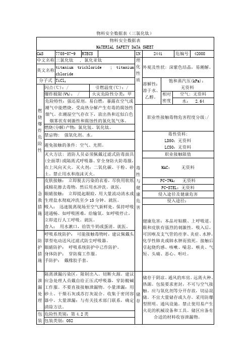
毒性与健康危害
职业性接触毒物危害程度分级:/
燃烧(分解)产物:氯化氢、氧化钛。
禁忌物:强氧化剂、水。
毒性资料:
LD50:无资料
LC50:无资料
避免接触的条件:空气、光照。
灭火方法:消防人员必须佩戴过滤式防毒面具(全面罩)或隔离式呼吸器、穿全身防火防毒服,在上风向灭火。灭火剂:二氧化碳、干粉、砂土。禁止用水和泡沫灭火。
PC-TWA:无资料
PC-STEL:无资料
侵入途径及健康危害
侵入途径:
健康危害:本品对粘膜、上呼吸道、眼和皮肤有强烈的刺激性。吸入后,可因喉及支气管的痉挛、炎症、水肿,化学性肺炎或肺水肿而致死。接触后引起烧灼感、咳嗽、喘息、喉炎、气短、头痛、恶心、呕吐。
防护措施
呼吸系统防护:可能接触毒物时,建议佩戴头罩型电动送风过滤式防尘呼吸器。
储存于阴凉、通风的库房。远离火种、热源。包装要求密封,不可与空气接触。应与氧化剂等分开存放,切忌混储。不宜大量储存或久存。采用防爆型照明、通风设施。禁止使用易产生火花的机械设备和工具。储区应备有合适的材料收容泄漏物。
包装
危险性类别:第4.2类
包装类别:052
分子式
TiCl3
溶解性:
溶于水、乙醇。
饱和蒸汽压(kPa):
无资料
燃烧爆炸危险性
闪点(℃):/
引燃温度(℃):/
爆炸极限(V%):/
火灾危险性分类:甲
相对
密度
空气:无资料
危险特性:强还原剂。易自燃,暴露在空气或潮气中能燃烧。受高热分解产生有毒的腐蚀性烟气。在潮湿空气存在下,放出热和近似白色烟雾状有刺激性和腐蚀性的氯化氢气体。
物料安全数据表(三氯化钛)
- 1、下载文档前请自行甄别文档内容的完整性,平台不提供额外的编辑、内容补充、找答案等附加服务。
- 2、"仅部分预览"的文档,不可在线预览部分如存在完整性等问题,可反馈申请退款(可完整预览的文档不适用该条件!)。
- 3、如文档侵犯您的权益,请联系客服反馈,我们会尽快为您处理(人工客服工作时间:9:00-18:30)。
Features• Low Power Consumption • Industry Standard Size• Industry Standard Pinout • Choice of Character Size7.6 mm (0.30 in), 10 mm (0.40 in), 10.9 mm (0.43 in), 14.2 mm (0.56 in), 20 mm (0.80 in)• Choice of ColorsAlGaAs Red, High Efficiency Red (HER), Yellow, Green• Excellent Appearance Evenly Lighted Segments±50° Viewing Angle• Design FlexibilityCommon Anode or Common CathodeSingle and Dual DigitLeft and Right Hand Decimal Points±1. Overflow Character• Categorized for Luminous IntensityYellow and Green Categorized for ColorUse of Like Categories Yields a Uniform Display• Excellent for Long Digit String Multiplexing DescriptionThese low current seven segment displays are designed for applica-tions requiring low power consumption. They are tested and selected for their excellent low current characteristics to ensure that the segments are matched at low currents. Drive currents as low as 1 mA per segment are available.Pin for pin equivalent displays are also available in a standard current or high light ambient design. The standard current displays are available in all colors and are ideal for most applica-tions. The high light ambient displays are ideal for sunlight ambients or long string lengths. For additional information see the 7.6 mm Micro Bright Seven Segment Displays, 10 mm Seven Segment Displays, 7.6 mm/10.9 mm Seven Segment Displays, 14.2 mm Seven Segment Displays, 20 mm Seven Segment Displays, or High Light Ambient Seven Segment Displays data sheets.Low Current Seven SegmentDisplays Technical Data HDSP-335x SeriesHDSP-555x SeriesHDSP-751x SeriesHDSP-A10x Series HDSP-A80x Series HDSP-A90x Series HDSP-E10x Series HDSP-F10x Series HDSP-G10x Series HDSP-H10x Series HDSP-K12x, K70x Series HDSP-N10x SeriesHDSP-N40x SeriesDevicesAlGaAs HER Yellow Green Package HDSP-HDSP-HDSP-HDSP-Description Drawing A1017511A801A9017.6 mm Common Anode Right Hand Decimal A A1037513A803A9037.6 mm Common Cathode Right Hand Decimal B A1077517A807A9077.6 mm Common Anode ±1. Overflow C A1087518A808A9087.6 mm Common Cathode ±1. Overflow D F10110 mm Common Anode Right Hand Decimal E F10310 mm Common Cathode Right Hand Decimal F F10710 mm Common Anode ±1. Overflow G F10810 mm Common Cathode ±1. Overflow H G10110 mm Two Digit Common Anode Right Hand Decimal X G10310 mm Two Digit Common Cathode Right Hand Decimal Y E100335010.9 mm Common Anode Left Hand Decimal I E101335110.9 mm Common Anode Right Hand Decimal J E103335310.9 mm Common Cathode Right Hand Decimal K E106335610.9 mm Universal ±1. Overflow[1]L H101555114.2 mm Common Anode Right Hand Decimal M H103555314.2 mm Common Cathode Right Hand Decimal N H107555714.2 mm Common Anode ±1. Overflow O H108555814.2 mm Common Cathode ±1. Overflow P K121K70114.2 mm Two Digit Common Anode Right Hand Decimal R K123K70314.2 mm Two Digit Common Cathode Right Hand Decimal S N10020 mm Common Anode Left Hand Decimal Q N101N40120 mm Common Anode Right Hand Decimal T N103N40320 mm Common Cathode Right Hand Decimal U N10520 mm Common Cathode Left Hand Decimal V N106N40620 mm Universal ±1. Overflow[1]W Note:1. Universal pinout brings the anode and cathode of each segment’s LED out to separate pins. See internal diagrams L or W.Part Numbering System5082-x xx x-x x x xxHDSP-x xx x-x x x xxMechanical Options[1]00: No mechanical optionColor Bin Options[1,2]0: No color bin limitationMaximum Intensity Bin[1,2]0: No maximum intensity bin limitationMinimum Intensity Bin[1,2]0: No minimum intensity bin limitationDevice Configuration/Color[1]G: GreenDevice Specific Configuration[1]Refer to respective datasheetPackage[1]Refer to Respective datasheetNotes:1. For codes not listed in the figure above, please refer to the respective datasheet or contact your nearest Agilent representative fordetails.2. Bin options refer to shippable bins for a part-number. Color and Intensity Bins are typically restricted to 1 bin per tube (excep-tions may apply). Please refer to respective datasheet for specific bin limit information.Package DimensionsPackage Dimensions (cont.)Package Dimensions (cont.)*The Side View of package indicates Country of Origin.Package Dimensions (cont.)Package Dimensions (cont.)Package Dimensions (cont.)Internal Circuit DiagramInternal Circuit Diagram (cont.)Absolute Maximum RatingsAlGaAs Red - HDSP-HERA10X/E10X/H10X HDSP-751X/Yellow GreenK12X/N10X/N40X335X/555X/HDSP-A80X HDSP-A90X Description F10X, G10X Series K70X Series Series Series Units Average Power per Segment or DP375264mW Peak Forward Current per 45mA Segment or DPDC Forward Current per15[1]15[2]mA Segment or DPOperating Temperature Range-20 to +100-40 to +100°C Storage Temperature Range -55 to +100°C Reverse Voltage per Segment 3.0V or DPWave Soldering Temperature for 3Seconds (1.60 mm [0.063 in.] below 250°C seating body)Notes:1. Derate above 91°C at 0.53 mA/°C.2. Derate HER/Yellow above 80°C at 0.38 mA/°C and Green above 71°C at 0.31 mA/°C.Electrical/Optical Characteristics at T A = 25°CAlGaAs RedDeviceSeriesHDSP-Parameter Symbol Min.Typ.Max.Units Test Conditions315600I F = 1 mA A10x3600I F = 5 mA330650I F = 1 mAF10x, G10x3900I F = 5 mA390650I F = 1 mA E10x Luminous Intensity/Segment[1,2]I Vµcd(Digit Average)3900I F = 5 mA400700I F = 1 mAH10x, K12x4200I F = 5 mA270590I F = 1 mAN10x, N40x3500I F = 5 mA1.6I F = 1 mAForward Voltage/Segment or DP V F 1.7V I F = 5 mA1.82.2I F = 20 mA PkAll Devices Peak WavelengthλPEAK645nmDominant Wavelength[3]λd637nmReverse Voltage/Segment or DP[4]V R 3.015V I R = 100 µATemperature Coefficient of∆V F/°C-2 mV mV/°CV F/Segment or DPA10x255F10x, G10x320E10x340Thermal Resistance LED RθJ-PIN°C/W/SegH10x, K12x Junction-to-Pin400N10x, N40x430High Efficiency RedDeviceSeriesHDSP-Parameter Symbol Min.Typ.Max.Units Test Conditions160270I F = 2 mA 751x1050I F = 5 mA200300I F = 2 mA Luminous Intensity/Segment[1,2]I V mcd(Digit Average)1200I F = 5 mA335x, 555x,K70x270370I F = 2 mA1480I F = 5 mA1.6I F = 2 mAForward Voltage/Segment or DP V F 1.7V I F = 5 mA2.1 2.5I F = 20 mA Pk All Devices Peak WavelengthλPEAK635nmDominant Wavelength[3]λd626nmReverse Voltage/Segment or DP[4]V R 3.030V I R = 100 µATemperature Coefficient of∆V F/°C-2mV/°CV F/Segment or DP751x200335x Thermal Resistance LED RθJ-PIN280°C/WJunction-to-Pin555x, K70x345YellowDeviceSeriesHDSP-Parameter Symbol Min.Typ.Max.Units Test Conditions Luminous Intensity/Segment[1,2]250420I F = 4 mA(Digit Average)I V mcd1300I F = 10 mA1.7I F = 4 mAForward Voltage/Segment or DP V F 1.8V I F = 5 mA A80x2.1 2.5I F = 20 mA PkPeak WavelengthλPEAK583nmDominant Wavelength[3,5]λd581.5585592.5nmReverse Voltage/Segment or DP[4]V R 3.030V I R = 100 µATemperature Coefficient of∆V F/°C-2mV/°CV F/Segment or DPThermal Resistance LED RθJ-PIN200°C/WJunction-to-PinGreenDeviceSeriesHDSP-Parameter Symbol Min.Typ.Max.Units Test Conditions Luminous Intensity/Segment[1,2]250475I F = 4 mA(Digit Average)I V mcd1500I F = 10 mA1.9I F = 4 mAForward Voltage/Segment or DP V F 2.0V I F = 10 mA A90x2.1 2.5I F = 20 mA PkPeak WavelengthλPEAK566nmDominant Wavelength[3,5]λd571577nmReverse Voltage/Segment or DP[4]V R 3.030V I R = 100 µATemperature Coefficient of∆V F/°C-2mV/°CV F/Segment or DPThermal Resistance LED RθJ-PIN200°C/WJunction-to-PinNotes:1. Device case temperature is 25°C prior to the intensity measurement.2. The digits are categorized for luminous intensity. The intensity category is designated by a letter on the side of the package.3. The dominant wavelength, λd, is derived from the CIE chromaticity diagram and is the single wavelength which defines the color of thedevice.4. Typical specification for reference only. Do not exceed absolute maximum ratings.5. The yellow (HDSP-A800) and Green (HDSP-A900) displays are categorized for dominant wavelength. The category is designated by anumber adjacent to the luminous intensity category letter.Figure 1. Maximum AllowableAverage or DC Current vs. Ambient Temperature.Figure 2. Forward Current vs.Forward Voltage.AlGaAs RedFigure 4. Relative Efficiency (Luminous Intensity per UnitCurrent) vs. Peak Current.Figure 3. Relative Luminous Intensity vs. DC Forward Current.Figure 5. Maximum Allowable Average or DC Current vs. Ambient Temperature.Figure 6. Forward Current vs. Forward Voltage.HER, Yellow, GreenFigure 7. Relative Luminous Intensityvs. DC Forward Current.Figure 8. Relative Efficiency(Luminous Intensity per UnitCurrent) vs. Peak Current.Intensity Bin Limits (mcd)AlGaAs RedHDSP-A10xIV Bin Category Min.Max.E0.3150.520F0.4280.759G0.621 1.16H0.945 1.71I 1.40 2.56J 2.10 3.84K 3.14 5.75L 4.708.55HDSP-E10x/F10x/G10xIV Bin Category Min.Max.D0.3910.650E0.5320.923F0.755 1.39G 1.13 2.08H 1.70 3.14HDSP-H10x/K12xIV Bin Category Min.Max.C0.4150.690D0.5650.990E0.810 1.50F 1.20 2.20G 1.80 3.30H 2.73 5.00I 4.097.50HDSP-N10xIV Bin Category Min.Max.A0.2700.400B0.3250.500C0.4150.690D0.5650.990E0.810 1.50F 1.20 2.20G 1.80 3.30H 2.73 5.00I 4.097.50Intensity Bin Limits (mcd), continued HERHDSP-751xIV Bin Category Min.Max.B0.1600.240C0.2000.300D0.2500.385E0.3150.520F0.4280.759G0.621 1.16HDSP-751xIV Bin Category Min.Max.B0.2400.366C0.3000.477D0.3910.650E0.5320.923F0.755 1.39G 1.13 2.08H 1.70 3.14HDSP-555x/K70xIV Bin Category Min.Max.A0.2700.400B0.3250.500C0.4150.690D0.5650.990E0.810 1.50F 1.20 2.20G 1.80 3.30H 2.73 5.00I 4.097.50Intensity Bin Limits (mcd), continued YellowHDSP-A80xIV Bin Category Min.Max.D0.2500.385E0.3150.520F0.4250.760G0.625 1.14H0.940 1.70I 1.40 2.56J 2.10 3.84K 3.14 5.76L 4.718.64M7.0713.00N10.6019.40O15.9029.20P23.9043.80Q35.8065.60GreenHDSP-A90xIV Bin Category Min.Max.E0.3150.520F0.4250.760G0.625 1.14H0.940 1.70I 1.40 2.56J 2.10 3.84K 3.14 5.76L 4.718.64M7.0713.00N10.6019.40O15.9029.20P23.9043.80Q35.8065.60Electrical/OpticalFor more information on electrical/optical characteristics, please see Application Note 1005.Contrast Enhancement For information on contrast enhancement, please see Application Note 1015.Soldering/Cleaning Cleaning agents from the ketone family (acetone, methyl ethyl ketone, etc.) and from the chorinated hydrocarbon family (methylene chloride, trichloro-ethylene, carbon tetrachloride, etc.) are not recommended for cleaning LED parts. All of these various solvents attack or dissolve the encapsulating epoxies used to form the package of plastic LED parts.For information on soldering LEDs, please refer to Application Note 1027.Note:All categories are established for classification of products. Productsmay not be available in all categories. Please contact your localAgilent representatives for further clarification/information.Color Categories/semiconductorsFor product information and a complete list ofdistributors, please go to our web site.For technical assistance call:Americas/Canada: +1 (800) 235-0312 or(916) 788 6763Europe: +49 (0) 6441 92460China: 10800 650 0017Hong Kong: (+65) 6271 2451India, Australia, New Zealand: (+65) 6271 2394Japan: (+81 3) 3335-8152(Domestic/International), or0120-61-1280(Domestic Only)Korea: (+65) 6271 2194Malaysia, Singapore: (+65) 6271 2054Taiwan: (+65) 6271 2654Data subject to change.Copyright © 2005 Agilent Technologies, Inc.Obsoletes 5988-8412ENJanuary 19, 20055989-0080EN。