Power-Efficient Wireless Structural Monitoring with Local Data
磁共振(磁谐振耦合)无线充电技术鼻祖级文章-英文原文

Wireless Power Transfer via Strongly Coupled Magnetic ResonancesAndré Kurs,1* Aristeidis Karalis,2 Robert Moffatt,1 J. D. Joannopoulos,1 Peter Fisher,3Marin Soljačić11Department of Physics, Massachusetts Institute of Technology, Cambridge, MA 02139, USA. 2Department of Electrical Engineering and Computer Science, Massachusetts Institute of Technology, Cambridge, MA 02139, USA. 3Department of Physics and Laboratory for Nuclear Science, Massachusetts Institute of Technology, Cambridge, MA 02139, USA.*To whom correspondence should be addressed. E-mail: akurs@Using self-resonant coils in a strongly coupled regime, we experimentally demonstrate efficient non-radiative power transfer over distances of up to eight times the radius of the coils. We demonstrate the ability to transfer 60W with approximately 40% efficiency over distances in excess of two meters. We present a quantitative model describing the power transfer which matches the experimental results to within 5%. We discuss practical applicability and suggest directions for further studies. At first glance, such power transfer is reminiscent of the usual magnetic induction (10); however, note that the usual non- resonant induction is very inefficient for mid-range applications.Overview of the formalism. Efficient mid-range power transfer occurs in particular regions of the parameter space describing resonant objects strongly coupled to one another. Using coupled-mode theory to describe this physical system (11), we obtain the following set of linear equationsIn the early 20th century, before the electrical-wire grid, Nikola Tesla (1) devoted much effort towards schemes to a&m(t)=(iωm-Γm)a m(t)+∑iκmn a n(t)+F m(t)n≠m(1)transport power wirelessly. However, typical embodiments (e.g. Tesla coils) involved undesirably large electric fields. During the past decade, society has witnessed a dramatic surge of use of autonomous electronic devices (laptops, cell- phones, robots, PDAs, etc.) As a consequence, interest in wireless power has re-emerged (2–4). Radiative transfer (5), while perfectly suitable for transferring information, poses a number of difficulties for power transfer applications: the efficiency of power transfer is very low if the radiation is omnidirectional, and requires an uninterrupted line of sight and sophisticated tracking mechanisms if radiation is unidirectional. A recent theoretical paper (6) presented a detailed analysis of the feasibility of using resonant objects coupled through the tails of their non-radiative fields for mid- range energy transfer (7). Intuitively, two resonant objects of the same resonant frequency tend to exchange energy efficiently, while interacting weakly with extraneous off- resonant objects. In systems of coupled resonances (e.g. acoustic, electro-magnetic, magnetic, nuclear, etc.), there is often a general “strongly coupled” regime of operation (8). If one can operate in that regime in a given system, the energy transfer is expected to be very efficient. Mid-range power transfer implemented this way can be nearly omnidirectional and efficient, irrespective of the geometry of the surrounding space, and with low interference and losses into environmental objects (6).Considerations above apply irrespective of the physical nature of the resonances. In the current work, we focus on one particular physical embodiment: magnetic resonances (9). Magnetic resonances are particularly suitable for everyday applications because most of the common materials do not interact with magnetic fields, so interactions with environmental objects are suppressed even further. We were able to identify the strongly coupled regime in the system of two coupled magnetic resonances, by exploring non-radiative (near-field) magnetic resonant induction at MHzfrequencies. where the indices denote the different resonant objects. The variables a m(t) are defined so that the energy contained in object m is |a m(t)|2, ωm is the resonant frequency of thatisolated object, and Γm is its intrinsic decay rate (e.g. due to absorption and radiated losses), so that in this framework anuncoupled and undriven oscillator with parameters ω0 and Γ0 would evolve in time as exp(iω0t –Γ0t). The κmn= κnm are coupling coefficients between the resonant objects indicated by the subscripts, and F m(t) are driving terms.We limit the treatment to the case of two objects, denoted by source and device, such that the source (identified by the subscript S) is driven externally at a constant frequency, and the two objects have a coupling coefficient κ. Work is extracted from the device (subscript D) by means of a load (subscript W) which acts as a circuit resistance connected to the device, and has the effect of contributing an additional term ΓW to the unloaded device object's decay rate ΓD. The overall decay rate at the device is therefore Γ'D= ΓD+ ΓW. The work extracted is determined by the power dissipated in the load, i.e. 2ΓW|a D(t)|2. Maximizing the efficiency η of the transfer with respect to the loading ΓW, given Eq. 1, is equivalent to solving an impedance matching problem. One finds that the scheme works best when the source and the device are resonant, in which case the efficiency isThe efficiency is maximized when ΓW/ΓD= (1 + κ2/ΓSΓD)1/2. It is easy to show that the key to efficient energy transfer is to have κ2/ΓSΓD> 1. This is commonly referred to as the strongcoupling regime. Resonance plays an essential role in thisDS S D'' power transfer mechanism, as the efficiency is improved by approximately ω2/ΓD 2 (~106 for typical parameters) compared to the case of inductively coupled non-resonant objects. Theoretical model for self-resonant coils. Ourexperimental realization of the scheme consists of two self- resonant coils, one of which (the source coil) is coupled inductively to an oscillating circuit, while the other (the device coil) is coupled inductively to a resistive load (12) (Fig. 1). Self-resonant coils rely on the interplay between distributed inductance and distributed capacitance to achieve resonance. The coils are made of an electrically conducting wire of total length l and cross-sectional radius a wound into Given this relation and the equation of continuity, one finds that the resonant frequency is f 0 = 1/2π[(LC )1/2]. We can now treat this coil as a standard oscillator in coupled-mode theory by defining a (t ) = [(L /2)1/2]I 0(t ).We can estimate the power dissipated by noting that the sinusoidal profile of the current distribution implies that the spatial average of the peak current-squared is |I 0|2/2. For a coil with n turns and made of a material with conductivity σ, we modify the standard formulas for ohmic (R o ) and radiation (R r ) µ0ω l a helix of n turns, radius r , and height h . To the best of our knowledge, there is no exact solution for a finite helix in the literature, and even in the case of infinitely long coils, the solutions rely on assumptions that are inadequate for our R o = 2σ 4πa µ πωr 42 ωh 2 (6)system (13). We have found, however, that the simple quasi- R =0 n 2 + (7)static model described below is in good agreementr ε 12 c3π3 c(approximately 5%) with experiment.We start by observing that the current has to be zero at the ends of the coil, and make the educated guess that the resonant modes of the coil are well approximated bysinusoidal current profiles along the length of the conducting wire. We are interested in the lowest mode, so if we denote by s the parameterization coordinate along the length of the conductor, such that it runs from -l /2 to +l /2, then the time- dependent current profile has the form I 0 cos(πs /l ) exp(i ωt ). It follows from the continuity equation for charge that the linear charge density profile is of the form λ0 sin(πs /l ) exp(i ωt ), so the two halves of the coil (when sliced perpendicularly to its axis) contain charges equal in magnitude q 0 = λ0l /π but opposite in sign.As the coil is resonant, the current and charge density profiles are π/2 out of phase from each other, meaning that the real part of one is maximum when the real part of the other is zero. Equivalently, the energy contained in the coil is 0The first term in Eq. 7 is a magnetic dipole radiation term(assuming r << 2πc /ω); the second term is due to the electric dipole of the coil, and is smaller than the first term for our experimental parameters. The coupled-mode theory decay constant for the coil is therefore Γ = (R o + R r )/2L , and its quality factor is Q = ω/2Γ.We find the coupling coefficient κDS by looking at the power transferred from the source to the device coil,assuming a steady-state solution in which currents and charge densities vary in time as exp(i ωt ).P =⎰d rE (r )⋅J (r ) =-⎰d r (A&S (r )+∇φS (r ))⋅J D (r ) at certain points in time completely due to the current, and at other points, completely due to the charge. Usingelectromagnetic theory, we can define an effective inductance L and an effective capacitance C for each coil as follows:=-1⎰⎰d r d r ' µJ &S(r ')+ρS(r ') 4π |r -r |ε0≡-i ωMI S I Dr '-r|r '-r |3⋅J D (r )(8)L =µ04π |I 0 |⎰⎰d r d r 'J (r )⋅J (r ')|r -r '|where the subscript S indicates that the electric field is due to the source. We then conclude from standard coupled-mode theory arguments that κDS = κSD = κ = ωM /2[(L S L D )1/2]. When 1 1 ρ(r )ρ(r ') the distance D between the centers of the coils is much larger= C 4πε 0 |q 0 | ⎰⎰d r d r ' |r -r '|(4)than their characteristic size, κ scales with the D -3dependence characteristic of dipole-dipole coupling. Both κ and Γ are functions of the frequency, and κ/Γ and the where the spatial current J (r ) and charge density ρ(r ) are obtained respectively from the current and charge densities along the isolated coil, in conjunction with the geometry of the object. As defined, L and C have the property that the efficiency are maximized for a particular value of f , which is in the range 1-50MHz for typical parameters of interest. Thus, picking an appropriate frequency for a given coil size, as we do in this experimental demonstration, plays a major role in optimizing the power transfer.1 2Comparison with experimentallydeterminedU =2 L |I 0 |parameters. The parameters for the two identical helical coils built for the experimental validation of the power 1 2 transfer scheme are h = 20cm, a = 3mm, r = 30 cm, and n = =2C|q 0 | (5)5.25. Both coils are made of copper. The spacing between loops of the helix is not uniform, and we encapsulate theuncertainty about their uniformity by attributing a 10% (2cm) uncertainty to h . The expected resonant frequency given these22dimensions is f0 = 10.56 ± 0.3MHz, which is about 5% off from the measured resonance at 9.90MHz.The theoretical Q for the loops is estimated to be approximately 2500 (assuming σ = 5.9 × 10⁷ m/Ω) but the measured value is Q = 950±50. We believe the discrepancy is mostly due to the effect of the layer of poorly conductingcopper oxide on the surface of the copper wire, to which the current is confined by the short skin depth (~20μm) at this frequency. We therefore use the experimentally observed Q and ΓS= ΓD= Γ = ω/2Q derived from it in all subsequent computations.We find the coupling coefficient κ experimentally by placing the two self-resonant coils (fine-tuned, by slightly adjusting h, to the same resonant frequency when isolated) a distance D apart and measuring the splitting in the frequencies of the two resonant modes. According to coupled-mode theory, this splitting should be ∆ω = 2[(κ2-Γ2)1/2]. In the present work, we focus on the case where the two coils are aligned coaxially (Fig. 2), although similar results are obtained for other orientations (figs. S1 and S2).Measurement of the efficiency. The maximum theoretical efficiency depends only on the parameter κ/[(L S L D)1/2] = κ/Γ, which is greater than 1 even for D = 2.4m (eight times the radius of the coils) (Fig. 3), thus we operate in the strongly- coupled regime throughout the entire range of distances probed.As our driving circuit, we use a standard Colpitts oscillator whose inductive element consists of a single loop of copper wire 25cm in radius(Fig. 1); this loop of wire couples inductively to the source coil and drives the entire wireless power transfer apparatus. The load consists of a calibrated light-bulb (14), and is attached to its own loop of insulated wire, which is placed in proximity of the device coil and inductively coupled to it. By varying the distance between the light-bulb and the device coil, we are able to adjust the parameter ΓW/Γ so that it matches its optimal value, given theoretically by (1 + κ2/Γ2)1/2. (The loop connected to the light-bulb adds a small reactive component to ΓW which is compensated for by slightly retuning the coil.) We measure the work extracted by adjusting the power going into the Colpitts oscillator until the light-bulb at the load glows at its full nominal brightness.We determine the efficiency of the transfer taking place between the source coil and the load by measuring the current at the mid-point of each of the self-resonant coils with a current-probe (which does not lower the Q of the coils noticeably.) This gives a measurement of the current parameters I S and I D used in our theoretical model. We then compute the power dissipated in each coil from P S,D=ΓL|I S,D|2, and obtain the efficiency from η = P W/(P S+ P D+P W). To ensure that the experimental setup is well described by a two-object coupled-mode theory model, we position the device coil such that its direct coupling to the copper loop attached to the Colpitts oscillator is zero. The experimental results are shown in Fig. 4, along with the theoretical prediction for maximum efficiency, given by Eq. 2. We are able to transfer significant amounts of power using this setup, fully lighting up a 60W light-bulb from distances more than 2m away (figs. S3 and S4).As a cross-check, we also measure the total power going from the wall power outlet into the driving circuit. The efficiency of the wireless transfer itself is hard to estimate in this way, however, as the efficiency of the Colpitts oscillator itself is not precisely known, although it is expected to be far from 100% (15). Still, the ratio of power extracted to power entering the driving circuit gives a lower bound on the efficiency. When transferring 60W to the load over a distance of 2m, for example, the power flowing into the driving circuit is 400W. This yields an overall wall-to-load efficiency of 15%, which is reasonable given the expected efficiency of roughly 40% for the wireless power transfer at that distance and the low efficiency of the Colpitts oscillator.Concluding remarks. It is essential that the coils be on resonance for the power transfer to be practical (6). We find experimentally that the power transmitted to the load drops sharply as either one of the coils is detuned from resonance. For a fractional detuning ∆f/f0 of a few times the inverse loaded Q, the induced current in the device coil is indistinguishable from noise.A detailed and quantitative analysis of the effect of external objects on our scheme is beyond the scope of the current work, but we would like to note here that the power transfer is not visibly affected as humans and various everyday objects, such as metals, wood, and electronic devices large and small, are placed between the two coils, even in cases where they completely obstruct the line of sight between source and device (figs. S3 to S5). External objects have a noticeable effect only when they are within a few centimeters from either one of the coils. While some materials (such as aluminum foil, styrofoam and humans) mostly just shift the resonant frequency, which can in principle be easily corrected with a feedback circuit, others (cardboard, wood, and PVC) lower Q when placed closer than a few centimeters from the coil, thereby lowering the efficiency of the transfer.When transferring 60W across 2m, we calculate that at the point halfway between the coils the RMS magnitude of the electric field is E rms= 210V/m, that of the magnetic field isH rms= 1A/m, and that of the Poynting vector is S rms=3.2mW/cm2 (16). These values increase closer to the coils, where the fields at source and device are comparable. For example, at distances 20cm away from the surface of the device coil, we calculate the maximum values for the fields to be E rms= 1.4kV/m, H rms= 8A/m, and S rms= 0.2W/cm2. The power radiated for these parameters is approximately 5W, which is roughly an order of magnitude higher than cell phones. In the particular geometry studied in this article, the overwhelming contribution (by one to two orders of magnitude) to the electric near-field, and hence to the near- field Poynting vector, comes from the electric dipole moment of the coils. If instead one uses capacitively-loaded single- turn loop design (6) - which has the advantage of confining nearly all of the electric field inside the capacitor - and tailors the system to operate at lower frequencies, our calculations show (17) that it should be possible to reduce the values cited above for the electric field, the Poynting vector, and the power radiated to below general safety regulations (e.g. the IEEE safety standards for general public exposure(18).) Although the two coils are currently of identical dimensions, it is possible to make the device coil small enough to fit into portable devices without decreasing the efficiency. One could, for instance, maintain the product of the characteristic sizes of the source and device coils constant, as argued in (6).We believe that the efficiency of the scheme and the power transfer distances could be appreciably improved by silver-plating the coils, which should increase their Q, or by working with more elaborate geometries for the resonant objects (19). Nevertheless, the performance characteristics of the system presented here are already at levels where they could be useful in practical applications.References and Notes1. N. Tesla, U.S. patent 1,119,732 (1914).2.J. M. Fernandez, J. A. Borras, U.S. patent 6,184,651(2001).3.A. Esser, H.-C. Skudelny, IEEE Trans. Indust. Appl. 27,872(1991).4.J. Hirai, T.-W. Kim, A. Kawamura, IEEE Trans. PowerElectron. 15, 21(2000).5.T. A. Vanderelli, J. G. Shearer, J. R. Shearer, U.S. patent7,027,311(2006).6.A. Karalis, J. D. Joannopoul os, M. Soljačić, Ann. Phys.,10.1016/j.aop.2007.04.017(2007).7.Here, by mid-range, we mean that the sizes of the deviceswhich participate in the power transfer are at least a few times smaller than the distance between the devices. For example, if the device being powered is a laptop (size ~ 50cm), while the power source (size ~ 50cm) is in thesame room as the laptop, the distance of power transfer could be within a room or a factory pavilion (size of the order of a fewmeters).8. T. Aoki, et al., Nature 443, 671 (2006).9.K. O’Brien, G. Scheible, H. Gueldner, 29th AnnualConference of the IEEE 1, 367(2003).10.L. Ka-Lai, J. W. Hay, P. G. W., U.S. patent7,042,196(2006).11.H. Haus, Waves and Fields in Optoelectronics(Prentice- Supporting Online Material/cgi/content/full/1143254/DC1SOM TextFigs. S1 to S530 March 2007; accepted 21 May 2007Published online 7 June 2007; 10.1126/science.1143254 Include this information when citing this paper.Fig. 1. Schematic of the experimental setup. A is a single copper loop of radius 25cm that is part of the driving circuit, which outputs a sine wave with frequency 9.9MHz. S and D are respectively the source and device coils referred to in the text. B is a loop of wire attached to the load (“light-bulb”). The various κ’s represent direct couplings between the objects indicated by the arrows. The angle between coil D and the loop A is adjusted to ensure that their direct coupling is zero, while coils S and D are aligned coaxially. The direct couplings between B and A and between B and S are negligible.Fig. 2. Comparison of experimental and theoretical values for κ as a function of the separation between coaxially aligned source and device coils (the wireless power transfer distance.) Fig. 3. Comparison of experimental and theoretical values for the parameter κ/Γ as a function of the wireless power transfer distance. The theory values are obtained by using the theoretical κ and the experimentally measured Γ. The shaded area represents the spread in the theoretical κ/Γ due to the 5% uncertainty in Q.Fig. 4. Comparison of experimental and theoretical efficiencies as functions of the wireless power transfer distance. The shaded area represents the theoretical prediction for maximum efficiency, and is obtained by inserting theHall, Englewood Cliffs, NJ, 1984).12.The couplings to the driving circuit and the load donot theoretical values from Fig. 3 into Eq. 2 [with Γκ2/Γ2 1/2 W /ΓD= (1 +have to be inductive. They may also be connected by awire, for example. We have chosen inductive coupling in the present work because of its easier implementation. 13.S. Sensiper, thesis, Massachusetts Institute of Technology(1951).14.We experimented with various power ratings from 5W to75W.15.W. A. Edson, Vacuum-Tube Oscillators (Wiley, NewYork,1953).16.Note that E ≠cμ0H, and that the fields are out of phaseand not necessarily perpendicular because we are not in a radiativeregime.17.See supporting material on Science Online.18.IEEE Std C95.1—2005 IEEE Standard for Safety Levelswith Respect to Human Exposure to Radio FrequencyElectromagnetic Fields, 3 kHz to 300 GHz (IEEE,Piscataway, NJ,2006).19. J. B. Pendry, Science 306, 1353 (2004).20. The authors would like to thank John Pendry forsuggesting the use of magnetic resonances, and Michael Grossman and Ivan Čelanović for technical assistance.This work was supported in part by the Materials Research Science and Engineering Center program of the National Science Foundation under Grant No. DMR 02-13282, by the U.S. Department of Energy under Grant No. DE-FG02-99ER45778, and by the Army Research Officethrough the Institute for Soldier Nanotechnologies under Contract No. DAAD-19-02-D0002.) ]. The black dots are the maximum efficiency obtained from Eq. 2 and the experimental values of κ/Γ from Fig. 3. The red dots present the directly measured efficiency,as described in thetext.。
奥林匹斯 OM-System 电动驱动器说明书

The Easily Assembled OM-System Motor Drive Units
CD Motor Drive 1 T he heart of t he group is t his basic motor drive
unit. It is fixed directly to t he camera base tr ipod socket with a clamping screw, and functions with the camera as one unit. The M.18V Control Grip 1 (with enclosed Battery Holder 1) or a Re lay Cord is attached t o t he base of the uni t.
Li ke all the other members of the OM-System, the Motor Drive Group is formed around the Olympus OM-l , in itself a radical new development in 35-SLR cameras that is revolutionizing this field of photography. The superior technical capabil ities of the OM-l, and its outstanding design features such as a 35% reduction in both weight and size, plus a decrease of more than half in shutter noise, make it the perfect complement for the world's lightest and smallest motor drive system.
Title Here, Up to Two Lines of Text - SILICA:在这里,上两行文字-二氧化硅精品文档

1
Power output level is set to lowest possible level that still ensures successful transmissions.
2
Data rate is set to MAX (1 Mbps)
3
Interference is detected
operates in the unlicensed 2.4 GHz ISM band
2.4 GHz
For Wireless Embedded Control
CyFi applications include wireless sensor networks, home automation, commercial building automation, remote controls, industrial process automation, and precision agriculture
CYFI Transceiver
• Operation in the 2.4-GHz ISM band • DSSS modulation for interference
immunity, enhanced co-location, and extended range • 1 Mbps/250 Kbps/125 Kbps data rates • 80 discrete channels • Up to +4 dBm output power • Up to -97 dBm receive sensitivity
Reliable. Simple. Power-Efficient.
CyFi uncompromisingly brings together reliability, simplicity, and power-efficiency along with the added benefits of PSoC®
Power Focus 6000 智能连接电源系统说明书

Full System Integration. Work with a platform that is easily integrated to any upper system through customer protocols, as well as open protocols. The Power Focus 6000 offers full integration –all in one, total intelligence.Virtual Stations. Stay connected whileexperiencing the advantage of cordless freedom.With flexible re-balancing and quick adaptations you have a productive solution. Virtual stations make product introductions quick and easy.Total solutions provider. Connect your smart and wireless tools, devices and accessories through one smart controller. T he Power Focus 6000 offers a total solution to your assembly needs, making Smart Factory a reality.A RELIABLE SOLUTION that is connected, flexible and built on state of the art technology. With a wide range of tools, accessories and services, Atlas Copco supports the vision of Industry 4.0. Experience the freedom of battery tools – and the quality assurance you gain from knowledge and control.We call it – Smart Connected Assembly.Maximized uptime.An embedded buffer battery maintains communicationwhile the main battery is being replaced. T his simply makes your tool ready, at all times.Complete connectivity. Enjoy the improved coverage with 2,4 and 5,0 Ghz gained by a new external antenna. T he Power Focus 6000 offers twoways of staying connected: infrastructure or pairing mode.4.24 7.05 Multitool concept. Connect several tools to one controller – and save money on installation and maintenance. Experience the benefits of a complete, smart connected solution – working for your specific needs.Full error proofing. Gain full traceability with the help of theintegrated barcode scanner. Y ou will have a process which improves productivity and saves costs by avoiding additional hand held scan devices.Focus on Ergonomics.Decrease operator fatigue and invest in a good ergonomic experience. T he STBx4 isdesigned with a well balanced tool on the grip and the best performance ratio weight, speed and torque.Robust andaccurate. When it comes to safety critical wireless tools, ourexperience keeps us inthe position as market leaders.With more than 10 years in the market– this robust tool has a well proven history in assembly lines around the world.Full System Interaction. With eHMI you have more than just results – gaining full process overview andinsights on for instance events, programs and Batch Sequence. And the possibility to select a repair program – system interaction anytime, anywhere.Start-upProductionMaintenanceError ProofingQuality Assurance OptimizationT Cordless AssemblySmart tools for the Smart FactoryATLAS COPCO IS A TOTAL SOLUTIONS PROVIDER.The advent of Industry 4.0 brings rapid changes and new challenges in terms of flexibility. With our Smart Connected Assembly, you maintain full integration and full process management.9833 2088 01。
无线电传输在双线圈及四线圈系统中的耦合模理论

Transmission of Wireless Power in Two-Coil and Four-Coil Systems using Coupled Mode TheoryManasi Bhutada, Vikaram Singh, ChiragWartyDept. of Electrical and Electronics EngineeringIntelligent Communication LabMumbai, India无线电传输在双线圈及四线圈系统中的耦合模理论电气与电子工程系智能通信实验室印度,孟买姓名:学号:班级:日期:2016年7月2日Abstract—Wireless Power Transfer (WPT) systems are considered as sophisticated alternatives for modern day wired power transmission. Resonance based wireless power delivery is an efficient technique to transfer power over a relatively long distance. This paper presents a summary of a two-coil wireless power transfer system with the design theory, detailed formulations and simulation results using the coupled mode theory (CMT). Further by using the same theory, it explains the four-coil wireless power transfer system and its comparison with the two-coil wireless transfer power system. A four-coil energy transfer system can be optimized to provide maximum efficiency at a given operating distance. Design steps to obtain an efficient power transfer system are presented and a design example is provided. Further, the concept of relay is described and how relay effect can allow more distant and flexible energy transmission is shown.摘要——无线电源传输(WPT)系统被认为是复杂的现代有线输电的替代品。
WLAN标准IEEE802_11ac_ad及其关键技术

在障碍物,收发设备能避开障碍物快 速重建一条新的链路进行通信。波束 赋形可以通过波束切换、相位加权天 线阵列、多天线阵列等不同的技术来 实现。
2.4 802.11ad支持多种物理层类 型及其应用场景 I E E E 802.11a d支持多种物理层
类型,包括控制物理层、单载波物理 层、低功率单载波物理层、O F D M物 理层。
WLAN标准 IEEE802.11ac/ad 及其关键技术
马满仓1 郑建勇2 郭 静2 卢继华2 1.中国电子系统工程研究所 2.北京理工大学
摘要
阐述了WLAN技术的发展现状,并详述IEEE802.11ac/ad标准中新增关键技术。MU-MIMO及MAC层增 强技术是IEEE802.11ac标准中的两大新增技术,而多频段互操作快速会话迁移(FST)技术以及自适应波 束赋形技术是I E E E802.11a d标准中的关键技术改进,同时进一步阐述了802.11a d标准中支持的不同物理 层类型及其应用场景。
● 针对无线视频、快速文件传输 等应用场景和60 G H z无线通信技术特 点 , 引 入 新 的 组 网 方 式 —— 个 人 基 本 服务集(PBSS)。
● 采用增强的安全协议和功率管 理技术。
● 支持在2.4 G H z、5 G H z和 60 GHz频带之间的快速会话转移。
● 支持与其他60 G H z系统(如 IEEE 802.15.3c及802.19)的共存。
2.3 自适应波束赋形 虽然IEEE 802.11ad在60 GHz的
频段上拥有更宽的带宽,并能够达 到更高的传输速率,但是相比于2.4 G H z或5 G H z频段其衰减更加严重。 为了解决这个问题IEEE 802.11ad采 用自适应波束赋形技术来实现10 m 以上大距离的数据传输。自适应波束 赋形通过自适应调整天线方向,减小 波束宽度以获得较高的天线增益,减 少干扰,扩大信号覆盖范围。此外, 如果在收发设备的视距传播路径上存
IDEA 2008 获奖作品

Computer Equipment
Gold winner
苹果MacBook Air笔记本 金奖 计算机设备类: 参与评奖的厂商: 苹果公司 (美国) 设计者 : 苹果公司 (美国)
苹果MacBook Air最大的卖点就是其超薄的机身造型,整体采用银灰色铝制外壳,LED屏 幕的应用以及英特尔专为苹果定制的处理器, 这些特点使得该机在厚度以及散热控制方 面均有较为出色的表现,除了出众的轻薄设计,该机在其他细节方面也极具特色。其触 摸板也是一个亮点,无缝设计和多触点技术能方便用户使用。作为目前最轻薄的 13寸机 型,MacBook Air堪称经典。
Replug Breakaway Audio Connector Series
An inadvertent yank on the audio cord sends the iPod falling, flying or worse, causing the audio plug to snap off inside the audio jack. Enter Replug, a series of adapters and extension cables that couple between headphones and devices, turning standard 3.5mm audio jacks into breakaway connections. Each product comprises a plug tip that is attached to the body via a resilient elastomeric ring. When too much force is applied, Replug simply detaches from itself, preventing catastrophic damage to the audio equipment. The product series currently includes headphone adapters and 6-foot long extension and audio cables.
麻省理工学院微电子实验室简介

MITResearch in nano- and micro- scale technologies is in the departments of Material Sci. and Eng. And Computer Sci. or Chemical Eng.MIT’s major micro and nano centers are MTL(Microsystem Technology Laboratories) which provide microelectronics fabrication lab/research/index.html.MTL is home to several research centers, including:∙The Center for Integrated Circuits and Systems (CICS) serves to promote closer technical relation between MIT's Microsystems Technology Lab's (MTL) research and industry, initiate and fund new research in integrated circuits and systems, produce more students skilled in the same area, address important research issues relevant to industry, and solicit ideas for new research from industry.∙The Intelligent Transportation Research Center (ITRC) focuses on the key Intelligent Transportation Systems (ITS) technologies, including an integrated network of transportation information, automatic crash & incident detection, notification and response, advanced crashavoidance technology, advanced transportation monitoring and management, etc., in order toimprove the safety, security, efficiency, mobile access, and environment. There are two emphasis for research conduced in the center: the integration of component technology research andsystem design research, and the integration of technical possibilities and social needs.∙MEMS@MIT is a collection of faculty/staff/students working in the broad area of a Micro/nano systems and MEMS. This center was created to serve as a forum for collectingintellectually-synergistic but organizationally diverse groups of researchers at MIT. In addition, we have organized an industrial interaction mechanism to catalyze the transfer of knowledge to the larger MEMS community.The research:Chemical/Mechanical/Optical MEMS1. A MEMS Electrometer for Gas Sensing2. A Single-Gated CNT Field-Ionizer Array with Open Architecture3. A MEMS Quadrupole that Uses a Meso-scaled DRIE-patterned Spring Assembly System4. Digital Holographic Imaging of Micro-structured and Biological Objects5. Multi-Axis Electromagnetic Moving-Coil Microactuator6. Multiphase Transport Phenomena in Microfluidic Systems7. Microfluidic Synthesis and Surface Engineering of Colloidal Nanoparticles8. Microreactor Enabled Multistep Chemical Synthesis9. Integrated Microreactor System10. Crystallization in Microfluidic Systems11. Microreactors for Synthesis of Quantum Dots12. A Large Strain, Arrayable Piezoelectric Microcellular Actuator13. MEMS Pressure-sensor Arrays for Passive Underwater Navigation14. A Low Contact Resistance MEMS-Relay15. "Fast Three-Dimensional Electrokinetic Pumps for Microfluidics16. Carbon Nanotube - CMOS Chemical Sensor Integration17. An Energy Efficient Transceiver for Wireless Micro-Sensor Applications18. Combinatorial Sensing Arrays of Phthalocyanine-based Field-effect Transistors19. Nanoelectromechanical Switches and Memories20. Integrated Carbon Nanotube Sensors21. Organic Photovoltaics with External Antennas22. Integrated Optical-wavelength-dependent Switching and Tuning by Use of Titanium Nitride (TiN)MEMS Technology23. Four Dimensional Volume Holographic Imaging with Natural Illumination24. White Light QD-LEDs25. Organic Optoelectronic Devices Printed by the Molecular Jet Printe26. Design and Measurement of Thermo-optics on SiliconBioMEMS1. A Microfabricated Platform for Investigating Multicellular Organization in 3-D Microenvironments2. Microfluidic Hepatocyte Bioreactor3. Micromechanical Control of Cell-Cell Interaction4. A MEMS Drug Delivery Device for the Prevention of Hemorrhagic Shock5. Multiwell Cell Culture Plate Format with Integrated Microfluidic Perfusion System6. Characterization of Nanofilter Arrays for Biomolecule Separation7. Patterned Periodic Potential-energy Landscape for Fast Continuous-flow BiomoleculeSeparation8. Continuous-flow pI-based Sorting of Proteins and Peptides in a Microfluidic Chip Using DiffusionPotential9. Cell Stimulation, Lysis, and Separation in Microdevices10. Polymer-based Microbioreactors for High Throughput Bioprocessing11. Micro-fluidic Bioreactors for Studying Cell-Matrix Interactions12. A Nanoscanning Platform for Biological Assays13. Label-free Microelectronic PCR Quantification14. Vacuum-Packaged Suspended Microchannel Resonant Mass Sensor for BiomolecularDetection15. Microbial Growth in Parallel Integrated Bioreactor Arrays16. BioMEMS for Control of the Stem-cell Microenvironment17. Microfluidic/Dielectrophoretic Approaches to Selective Microorganism Concentration18. Microfabricated Approaches for Sorting Cells Using Complex Phenotypes19. A Continuous, Conductivity-Specific Micro-organism Separator20. Polymer Waveguides for Integrated BiosensorsEnabling Technology1. A Double-gated CNF Tip Array for Electron-impact Ionization and Field Ionization2. A Double-gated Silicon Tip, Electron-Impact Ionization Array3. A Single-Gated CNT Field-Ionizer Array with Open Architecture4. Aligning and Latching Nano-structured Membranes in 3D Micro-Structures5. Characterization and Modeling of Non-uniformities in DRIE6. Understanding Uniformity and Manufacturability in MEMS Embossing7. Atomic Force Microscopy with Inherent Disturbance Suppression for Nanostructure Imaging8. Vacuum-Sealing Technologies for Micro-chemical Reactors9. Direct Patterning of Organic Materials and Metals Using Micromachined Printheads10. MEMS Vacuum Pump11. Rapid and Shape-Controlled Growth of Aligned Carbon Nanotube Structures12. Prediction of Variation in Advanced Process Technology Nodes13. Parameterized Model Order Reduction of Nonlinear Circuits and MEMS14. Development of Specialized Basis Functions and Efficient Substrate Integration Techniques forElectromagnetic Analysis of Interconnect and RF Inductors15. A Quasi-convex Optimization Approach to Parameterized Model-order Reduction16. Amorphous Zinc-Oxide-Based Thin-film Transistors17. Magnetic Rings for Memory and Logic Devices18. Studies of Field Ionization Using PECVD-grown CNT Tips19. Growth of Carbon Nanotubes for Use in Origami Supercapacitors20. Self-Alignment of Folded, Thin-Membranes via Nanomagnet Attractive Forces21. Control System Design for the Nanostructured Origami™ 3D Nanofabrication Process22. Measuring Thermal and Thermoelectric Properties of Single Nanowires and Carbon Nanotubes23. Nanocomposites as Thermoelectric Materials24. CNT Assembly by Nanopelleting25. Templated Assembly by Selective Removal26. Building Three-dimensional Nanostructures via Membrane FoldingPower MEMS1. Hand-assembly of an Electrospray Thruster Electrode Using Microfabricated Clips2. A Fully Microfabricated Planar Array of Electrospray Ridge Emitters for Space PropulsionApplications3. Thermal Management in Devices for Portable Hydrogen Generation4. Autothermal Catalytic Micromembrane Devices for Portable High-Purity Hydrogen Generation5. Self-powered Wireless Monitoring System Using MEMS Piezoelectric Micro Power Generator6. An Integrated Multiwatt Permanent Magnet Turbine Generator7. Micro-scale Singlet Oxygen Generator for MEMS-based COIL Lasers8. A Thermophotovoltaic (TPV) MEMS Power Generator9. MEMS Vibration Harvesting for Wireless Sensors10. Fabrication and Structural Design of Ultra-thin MEMS Solid Oxide Fuel Cells11. Tomographic Interferometry for Detection of Nafion® Membrane Degradation in PEM Fuel Cells∙The Center for Integrated Photonic Systems (CIPS) mission is to create a meaningful vision of the future, a framework for understanding how technology, industry and business interact and evolve together in the future is required. Models provide us with a process for analyzing the many complex factors that shape this industry and the progress of related technologies.The materials processing center .Making matter meet human needsResearchThe Center brings together MIT faculty and research staff from diverse specialties to collaborate on interdisciplinary materials problems. Center research involves over 150 faculty, research staff, visiting scientists, and graduate and undergraduate students.MPC researchers cover the full range of advanced materials, processes, and technologies, including∙electronic materials∙batteries & fuel cells∙polymers∙advanced ceramics∙materials joining∙composites of all types∙photonics∙electrochemical processing ∙traditional metallurgy∙environmental degradation∙materials modeling- many scale ∙materials systems analysis∙nanostructured materials∙magnetic materials and processes ∙biomaterials∙materials economicsFaculty ProfilesA.I. AkinwandeFlat panel displays,Vacuum Microelectronics and its application to flat panel displays, RF power sources, and sensors. Wide bandgap semiconductors and applications to flat panel displays, UV emitters and RF power sourcesView current research abstracts (pdf)G. BarbastathisBiomedical design instrumentation; precision engineering robotics; volume holographic architectures for data storage, color-selective tomographic imaging, and super-resolving confocal microscopy; interferometric surface characterization; and adaptive micro-opto-mechanics. Optical MEMS.View current research abstracts (pdf)View group web siteM. BazantResearch focuses on transport phenomena in materials and engineering systems, especially diffusion coupled to fluid flow. My group is currently studying granular flow in pebble-bed nuclear reactors, nonlinear electrokinetic flows in microfludic devices, ion transport in thin-film lithium batteries, and advection-diffusion-limited aggregation.View current research abstracts (pdf)View group web siteS. BhatiaResearch focuses on applications of micro- and nanotechnology to tissue repair and regeneration. Emphasis on development of microfabrication tools to improve cellular therapies for liver disease, living cell arrays to study stem cell biology, and nanoparticles for cancer diagnosis and treatment.View current research abstracts (pdf)View group web siteD. BoningSemiconductor manufacturing. Modeling and control of chemical mechanical polishing. Variation modeling and reduction in fabrication processes, devices, and interconnects. Run by run and feedback control for quality and environment in semiconductor fabrication. Software systems for distributed and collaborative computer aided design and fabrication.View current research abstracts (pdf)View group web siteA.P. ChandrakasanDesign of digital integrated circuits and systems. Emphasis on the energy efficient implementation of distributed microsensor and signal processing systems. Protocols and Algorithms for Wireless Systems. Circuits techniques for deep sub-micron technologies.View current research abstracts (pdf)View group web siteG. ChenMicro- and nanoscale heat transfer and energy conversion with applications in thermoelectrics, photonics, and microelectronics; nano-mechanical devices and micro-electro-mechanical systems; radiation and electromagnetic metamaterials.View current research abstracts (pdf)View group web siteM. CulpepperResearch focuses on precision interfaces, precision manufacturing, design for manufacturing, applying precision principles as enabling technologies in multi-disciplinary product design: electronic test equipment, automotive systems, precision compliant mechanisms.View current research abstracts (pdf)View group web siteL. DanielResearch focuses on engineering design applications to drive research in simulation and optimization algorithms and software, design of microfabricated inductors.View current research abstracts (pdf)View group web siteP. DoyleUnderstanding the dynamics of single polymers and biomolecules under forces and fields; lab-on-chip separations, polymer rheology. DNA electrophoresis in microdevices. Superparamagnetic colloids. Brownian Dynamics simulations of complex molecules. Microheology of biopolymers.View current research abstracts (pdf)View group web siteA. EpsteinSmart engines, turbine heat transfer and aerodynamics, advanced diagnostic instrumentation, turbomachinery noise, environmental impact of aircraft.View current research abstracts (pdf)View group web siteD. FreemanBiological micromechanics, MEMS, light microscopy and computer microvision.View current research abstracts (pdf)牋牋牋牋牋牋牋牋牋牋牋?牋View group web siteM. GrayMicrofabricated devices for use in diagnostic medicine and biological research. Particle and fuid analysis of flowing media using absorbance and fluorescence techniques as a means for understanding cell or organism metabolism and phenotypic expression.View group web siteJ. HanBioMEMS, biomolecule analysis, micro/nanofluidics, micro-analysis systems.View current research abstracts (pdf)View group web siteJ. JacobsonDevelopment of processes for directly and continuously printing communication, computation, and displays onto arbitrary substrates. Electronic control of biomolecules.View group web siteK. JensenMicrofabrication and characterization of devices and systems for chemical synthesis and detection, hydrocarbon fuel conversion to electrical energy, bioprocessing and bioanalytics. Multiscale simulation of transport and reaction processes. Chemical vapor deposition of polymer, metal, and semiconductor thin films. Synthesis and characterization of quantum dot composite materials.View current research abstracts (pdf)View group web siteR. KarnikMicro- and nanofluidic systems. Application of transport phenomena in nanofluidics for flow control, separation, sensing. Microfluidic devices for studying chemical kinetics and nanoparticle synthesis.View group web siteS.G. KimSystems Design and Manufacturing, MEMS for optical beam steering, microphotonic packaging and active alignment, micro power generation, massive parallel positional assembly of nanostructures, and nano actuator array.View current research abstracts (pdf)View group web siteJ.H. LangAnalysis, design and control of electromechanical systems. Application to traditional electromagnetic actuators, micron scale actuators and sensors, and flexible structures.View current research abstracts (pdf)View group web siteC. LivermoreMicroElectroMechanical Systems (MEMS). Design and fabrication of high power microsystems. Nanoscale self-assembly and manufacturing.View current research abstracts (pdf)View group web siteS. ManalisApplication of micro- and nanofabrication technologies towards the development of novel methods for probing biological systems. Current projects focus on electrical and mechanical detection schemes for analyzing DNA, proteins, and cells.View current research abstracts (pdf)View group web siteD.J. PerreaultAnalysis, design, and control of cellular power converter architectures. DC/DC Converters fordual-voltage electrical systems. Electrical system transient investigation. Exploration of non-conventional electricity sources for motor vehicles.View group web siteM.A. SchmidtMicroElectroMechanical Systems (MEMS). Microfabrication technologies for integrated circuits, sensors, and actuators. Design of microsensor and microactuator systems.View current research abstracts (pdf)A. SlocumPrecision Engineering; Machine Design; Product Design.View current research abstracts (pdf)View group web siteC.V. ThompsonProcessing, structure, properties, performance, and reliability of thin films and structures for micro- and nano-devices and systems. Reliability and Interconnect.View current research abstracts (pdf)View group web siteT. ThorsenIntegrating microfluidic design and fabrication techniques, electronics and optics with biochemical applications. Optimizing channel dimensions, geometry, and layout to generate 3-D fluidic networks that are functional and scalable. Interface development to combine microfluidic technologies with pneumatic valves, MEMS-based detector systems, and software-based data acquisition and interpretation, creating devices for fundamental research and diagnostic applications.View current research abstracts (pdf)View group web siteH.L. TullerCharacterize and understand key electronic, microstructural, and optical properties of advanced ceramic materials. Fabrication andcharacterization of crystals, ceramics and glasses for electronic devices, lasers, electrochemical energy conversion, sensors and actuators.View current research abstracts (pdf)View group web siteJ. VoldmanBiological applications of microsystem technology. Engineering and use of microsystems for analysis and engineering of single cells. Physical and electrical cell manipulation. Design, modeling, microfabrication, and testing of microfluidic biological devices employing unconventional materials and fabrication processes. Electromechanics at the microscale.View current research abstracts (pdf)View group web siteE. N. WangDevelopment of MEMS/NEMS for: Biochemical sensing and detection; Thermal management of high power density and high performance systems; Diagnostics for biological systems and bio-functionality View group web siteB. WardlePower MEMS microyhydraulics, structural health monitoring, nanocomposites, damageresistance/tolerance of advanced composite materials, cost modeling in the structural design process, conversion of technology to value.View current research abstracts (pdf)View group web siteJ. WhiteTheoretical and practical aspects of numberical algorithms for problems in circuit, device, interconnect, packaging, and micromechanical system design; parallel numerical algorithms; interaction between numerical algorithms and computer architecture.View current research abstracts (pdf)View group web siteLaser-cooling brings large object near absolute zeroAnne Trafton, News OfficeApril 5, 2007Using a laser-cooling technique that could one day allow scientists to observe quantum behavior in large objects, MIT researchers have cooled a coin-sized object to within one degree of absolute zero.Fig.1Assistant professor Nergis Mavalvala, left, and Ph.D. student Thomas Corbitt are part of an international team that has devised a way to cool large objects to near absolute zero. Enlarge image (no JavaScript)Fig.Super-mirrorMIT researchers have developed a technique to cool this dime-sized mirror (small circle suspended in the center of large metal ring) to within one degree of absolute zero. Enlarge image (no JavaScript)Fig.2Assistant professor Nergis Mavalvala, right, and Ph.D. student Thomas Corbitt look over the laser system they use to cool a coin-sized mirror to within one degree of absolute zero. Enlarge image (no JavaScript)。
Silicon Labs EFR32MG 2.4 GHz 19.5 dBm 无线模组板参考手册说明书

EFR32MG 2.4 GHz 19.5 dBm Radio BoardBRD4151A Reference Manualance, low energy wireless solution integrated into a small formfactor package.By combining a high performance 2.4 GHz RF transceiver with an energy efficient 32-bitMCU, the family provides designers the ultimate in flexibility with a family of pin-compati-ble devices that scale from 128/256 kB of flash and 16/32 kB of RAM. The ultra-lowpower operating modes and fast wake-up times of the Silicon Labs energy friendly 32-bit MCUs, combined with the low transmit and receive power consumption of the 2.4GHz radio, result in a solution optimized for battery powered applications.To develop and/or evaluate the EFR32 Mighty Gecko, the EFR32MG Radio Board canbe connected to the Wireless Starter Kit Mainboard to get access to display, buttons andadditional features from Expansion Boards.Introduction 1. IntroductionThe EFR32 Mighty Gecko Radio Boards provide a development platform (together with the Wireless Starter Kit Mainboard) for the Silicon Labs EFR32 Mighty Gecko Wireless System on Chips and serve as reference designs for the matching network of the RF inter-face.The BRD4151A Radio Board is designed to operate in the 2400-2483.5 MHz band with the RF matching network optimized to operate with 19.5 dBm output power.To develop and/or evaluate the EFR32 Mighty Gecko, the BRD4151A Radio Board can be connected to the Wireless Starter Kit Main-board to get access to display, buttons and additional features from Expansion Boards and also to evaluate the performance of the RF interface.2. Radio Board Connector2.1 IntroductionThe board-to-board connector scheme allows access to all EFR32MG1 GPIO pins as well as the RESETn signal. For more information on the functions of the available pin functions, see the EFR32MG1 data sheet.2.2 Radio Board Connector Pin AssociationsThe figure below shows the pin mapping on the connector to the radio pins and their function on the Wireless Starter Kit Mainboard.GND F9 / PA3 / VCOM.#RTS_#CS 3v3UIF_BUTTON1 / PF7 / P36P200Upper RowNC / P38NC / P40NC / P42NC / P44DEBUG.TMS_SWDIO / PF1 / F0DISP_ENABLE / PD15 / F14UIF_BUTTON0 / PF6 / F12DISP_EXTCOMIN / PD13 / F10VCOM.#CTS_SCLK / PA2 / F8#RESET / F4DEBUG.TDO_SWO / PF2 / F2DISP_SI / PC6 / F16VCOM.TX_MOSI / PA0 / F6PTI.DATA / PB12 / F20DISP_EXTCOMIN / PD13 / F18USB_VBUS5VBoard ID SCLGND Board ID SDAUSB_VREG F7 / PA1 / VCOM.RX_MISO F5 / PA5 / VCOM_ENABLE F3 / PF3 / DEBUG.TDI F1 / PF0 / DEBUG.TCK_SWCLK P45 / NC P43 / NCP41 / NCP39 / NCP37 / High / SENSOR_ENABLEF11 / PF5 / UIF_LED1F13 / PF7 / UIF_BUTTON1F15 / PC8 / DISP_SCLK F17 / PD14 / DISP_SCS F19 / PB13 / PTI.SYNC F21 / PB11 / PTI.CLK GNDVMCU_INVCOM.#CTS_SCLK / PA2 / P0P201Lower RowVCOM.#RTS_#CS / PA3 / P2PD10 / P4PD11 / P6GND VRF_INP35 / PD15 / DISP_ENABLE P7 / PC9P5 / PC8 / DISP_SCLK P3 / PC7P1 / PC6 / DISP_SI P33 / PD14 / DISP_SCSP31 / PD13 / DISP_EXTCOMIN P29 / NCP27 / NC P25 / NC P23 / NC P21 / NC P19 / NC P17 / NC P15 / NC P13 / PC11P11 / PA1 / VCOM.RX_MISO P9 / PA0 / VCOM.TX_MOSI UIF_BUTTON0 / PF6 / P34UIF_LED1 / PF5 / P32UIF_LED0 / PF4 / P30DEBUG.TDO_SWO / PF2 / P28DEBUG.TMS_SWDIO / PF1 / P26DEBUG.TCK_SWCLK / PF0 / P24PTI.SYNC / PB13 / P22PTI.DATA / PB12 / P20PTI.CLK / PB11 / P18VCOM_ENABLE / PA5 / P16PA4 / P14PC10 / P12DEBUG.TDI / PF3 / P10PD12 / P8Figure 2.1. BRD4151A Radio Board Connector Pin MappingRadio Board Connector3. Radio Board Block Summary3.1 IntroductionThis section gives a short introduction to the blocks of the BRD4151A Radio Board.3.2 Radio Board Block DiagramThe block diagram of the EFR32MG Radio Board is shown in the figure below.Figure 3.1. BRD4151A Block Diagram3.3 Radio Board Block Description3.3.1 Wireless MCUThe BRD4151A EFR32 Mighty Gecko Radio Board incorporates an EFR32MG1P232F256GM48 Wireless System on Chip featuring 32-bit Cortex-M4 with FPU core, 256 kB of flash memory and 32 kB of RAM and a 2.4 GHz band transceiver with output power up to 19.5 dBm. For additional information on the EFR32MG1P232F256GM48, refer to the EFR32MG1 Data Sheet.3.3.2 LF Crystal Oscillator (LFXO)The BRD4151A Radio Board has a 32.768 kHz crystal mounted.3.3.3 HF Crystal Oscillator (HFXO)The BRD4151A Radio Board has a 38.4 MHz crystal mounted.3.3.4 Matching Network for 2.4 GHzThe BRD4151A Radio Board incorporates a 2.4 GHz matching network which connects the 2.4 GHz TRX pin of the EFR32MG1 to the one on-board printed Inverted-F antenna. The component values were optimized for the 2.4 GHz band RF performace and current con-sumption with 19.5 dBm output power.For detailed description of the matching network, see Chapter 4.2.1 Description of the 2.4 GHz RF Matching.| Smart. Connected. Energy-friendly.Rev. 1.7 | 33.3.5 Inverted-F AntennaThe BRD4151A Radio Board includes a printed Inverted-F antenna (IFA) tuned to have close to 50 Ohm impedance at the 2.4 GHz band.For detailed description of the antenna see Chapter 4.5 Inverted-F Antenna.3.3.6 UFL ConnectorTo be able to perform conducted measurements, Silicon Labs added an UFL connector to the Radio Board. The connector allows an external 50 Ohm cable or antenna to be connected during design verification or testing.Note: By default the output of the matching network is connected to the printed Inverted-F antenna by a series component. It can be connected to the UFL connector as well through a series 0 Ohm resistor which is not mounted by default. For conducted measurements through the UFL connector the series component to the antenna should be removed and the 0 Ohm resistor should be mounted (see Chapter 4.2 Schematic of the RF Matching Network for further details).3.3.7 Radio Board ConnectorsTwo dual-row, 0.05” pitch polarized connectors make up the EFR32MG Radio Board interface to the Wireless Starter Kit Mainboard. For more information on the pin mapping between the EFR32MG1P232F256GM48 and the Radio Board Connector, refer to Chapter 2.2 Radio Board Connector Pin Associations.4. RF Section4.1 IntroductionThis section gives a short introduction to the RF section of the BRD4151A.4.2 Schematic of the RF Matching NetworkThe schematic of the RF section of the BRD4151A Radio Board is shown in the following figure.U1BPath Inverted-F Antenna2.4 GHz Matching Figure 4.1. Schematic of the RF Section of the BRD4151A4.2.1 Description of the 2.4 GHz RF MatchingThe 2.4 GHz matching connects the 2G4RF_IOP pin to the on-board printed Inverted-F Antenna. The 2G4RF_ION pin is connected to ground. For higher output powers (13 dBm and above) beside the impedance matching circuitry it is recommended to use additional harmonic filtering as well at the RF output. The targeted output power of the BRD4151A board is 19.5 dBm. As a result, the RF output of the IC is connected to the antenna through a four-element impedance matching and harmonic filter circuitry.For conducted measurements the output of the matching network can also be connected to the UFL connector by relocating the series R1 resistor (0 Ohm) to the R2 resistor position between the output of the matching and the UFL connector.4.3 RF Section Power SupplyOn the BRD4151A Radio Board the supply pin of the RF Analog Power (RFVDD) is connected directly ot the output of the on-chip DC-DC converter while the supply for the 2.4 GHz PA (PAVDD) is provided directly by the mainboard. This way, by default, the DC-DC converter provides 1.8 V for the RF analog section, the mainboard provides 3.3 V for the PA (for details, see the schematic of the BRD4151A).4.4 Bill of Materials for the 2.4 GHz MatchingThe Bill of Materials of the 2.4 GHz matching network of the BRD4151A Radio Board is shown in the following table.Table 4.1. Bill of Materials for the BRD4151A 2.4 GHz 19.5 dBm RF Matching Network | Smart. Connected. Energy-friendly.Rev. 1.7 | 54.5 Inverted-F AntennaThe BRD4151A Radio Board includes an on-board printed Inverted-F Antenna tuned for the 2.4 GHz band. Due to the design restric-tions of the Radio Board the input of the antenna and the output of the matching network can't be placed directly next to each other. Therefore, a 50 Ohm transmission line was necessary to connect them. The resulting impedance and reflection measured at the output of the matcing network are shown in the following figure. As it can be observed the impedance is close to 50 Ohm (the reflection is better than -10 dB) for the entire 2.4 GHz band.Figure 4.2. Impedance and Reflection of the Inverted-F Antenna of the BRD4151A| Smart. Connected. Energy-friendly.Rev. 1.7 | 65. Mechanical DetailsThe BRD4151A EFR32 Mighty Gecko Radio Board is illustrated in the figures below.45 mmFigure 5.1. BRD4151A Top View5 mm ConnectorConnectorFigure 5.2. BRD4151A Bottom ViewMechanical DetailsRev. 1.7 | 7EMC Compliance 6. EMC Compliance6.1 IntroductionCompliance of the fundamental and harmonic levels is tested against the following standards:• 2.4 GHz:•ETSI EN 300-328•FCC 15.2476.2 EMC Regulations for 2.4 GHz6.2.1 ETSI EN 300-328 Emission Limits for the 2400-2483.5 MHz BandBased on ETSI EN 300-328 the allowed maximum fundamental power for the 2400-2483.5 MHz band is 20 dBm EIRP. For the unwan-ted emissions in the 1 GHz to 12.75 GHz domain the specified limit is -30 dBm EIRP.6.2.2 FCC15.247 Emission Limits for the 2400-2483.5 MHz BandFCC 15.247 allows conducted output power up to 1 Watt (30 dBm) in the 2400-2483.5 MHz band. For spurious emmissions the limit is -20 dBc based on either conducted or radiated measurement, if the emission is not in a restricted band. The restricted bands are speci-fied in FCC 15.205. In these bands the spurious emission levels must meet the levels set out in FCC 15.209. In the range from 960 MHz to the frequency of the 5th harmonic it is defined as 0.5 mV/m at 3 m distance (equals to -41.2 dBm in EIRP).Additionally, for spurious frequencies above 1 GHz, FCC 15.35 allows duty-cycle relaxation to the regulatory limits. For the EmberZNet PRO the relaxation is 3.6 dB. Therefore, the -41.2 dBm limit can be modified to -37.6 dBm.If operating in the 2400-2483.5 MHz band the 2nd, 3rd and 5th harmonics can fall into restricted bands. As a result, for those the -37.6 dBm limit should be applied. For the 4th harmonic the -20 dBc limit should be applied.6.2.3 Applied Emission Limits for the 2.4 GHz BandThe above ETSI limits are applied both for conducted and radiated measurements.The FCC restricted band limits are radiated limits only. Besides that, Silicon Labs applies those to the conducted spectrum i.e., it is assumed that, in case of a custom board, an antenna is used which has 0 dB gain at the fundamental and the harmonic frequencies. In that theoretical case, based on the conducted measurement, the compliance with the radiated limits can be estimated.The overall applied limits are shown in the table below.Table 6.1. Applied Limits for Spurious Emissions for the 2.4 GHz Band | Smart. Connected. Energy-friendly.Rev. 1.7 | 87. RF Performance7.1 Conducted Power MeasurementsDuring measurements, the EFR32MG Radio Board was attached to a Wireless Starter Kit Mainboard which was supplied by USB. The voltage supply for the Radio Board was 3.3 V.7.1.1 Conducted Measurements in the 2.4 GHz bandThe BRD4151A board was connected directly to a Spectrum Analyzer through its UFL connector (the R1 resistor (0 Ohm) was removed and a 0 Ohm resistor was soldered to the R2 resistor position). During measurements, the voltage supply for the board was 3.3 V provi-ded by the mainboard. The supply for the radio (RFVDD) was 1.8 V provided by the on-chip DC-DC converter, the supply for the power amplifier (PAVDD) was 3.3 V (for details, see the schematic of the BRD4151A). The transceiver was operated in continuous carrier transmission mode. The output power of the radio was set to the maximum level.The typical output spectrum is shown in the following figure.Figure 7.1. Typical Output Spectrum of the BRD4151AAs it can be observed, the fundamental is slightly lower than 19.5 dBm and the strongest unwanted emission is the double-frequency harmonic and it is under the -37.6 dBm applied limit.Note: The conducted measurement is performed by connecting the on-board UFL connector to a Spectrum Analyzer through an SMA Conversion Adapter (P/N: HRMJ-U.FLP(40)). This connection itself introduces approximately a 0.3 dB insertion loss.RF PerformanceRev. 1.7 | 97.2 Radiated Power MeasurementsDuring measurements, the EFR32MG Radio Board was attached to a Wireless Starter Kit Mainboard which was supplied by USB. The voltage supply for the Radio Board was 3.3 V. The radiated power was measured in an antenna chamber by rotating the DUT 360degrees with horizontal and vertical reference antenna polarizations in the XY , XZ and YZ cuts. The measurement axes are shown inthe figure below.Figure 7.2. DUT: Radio Board with the Wireless Starter Kit Mainboard (Illustration)Note: The radiated measurement results presented in this document were recorded in an unlicensed antenna chamber. Also the radi-ated power levels may change depending on the actual application (PCB size, used antenna, and so on). Therefore, the absolute levels and margins of the final application are recommended to be verified in a licensed EMC testhouse.7.2.1 Radiated Measurements in the 2.4 GHz bandFor the transmitter antenna, the on-board printed Inverted-F antenna of the BRD4151A board was used (the R1 resistor (0 Ohm) was mounted). During the measurements the board was attached to a Wireless Starter Kit Mainboard (BRD4001 (Rev. A02) ) which was supplied through USB. During measurements, the voltage supply for the board was 3.3 V provided by the mainboard. The supply for the radio (RFVDD) was 1.8 V provided by the on-chip DC-DC converter, the supply for the power amplifier (PAVDD) was 3.3 V (for details, see the schematic of the BRD4151A). The transceiver was operated in continuous carrier transmission mode. The output power of the radio was set to the maximum level.The results are shown in the table below.Table 7.1. Maximums of the Measured Radiated Powers of BRD4151AAs it can be observed, thanks to the high gain of the Inverted-F antenna, the level of the fundamental is higher than 19.5 dBm. The strongest harmonic is the double-frequency one but its level is under -45 dBm.RF PerformanceEMC Compliance Recommendations 8. EMC Compliance Recommendations8.1 Recommendations for 2.4 GHz ETSI EN 300-328 complianceAs it was shown in the previous chapter, the radiated power of the fundamental of the BRD4151A EFR32 Mighty Gecko Radio Board complies with the 20 dBm limit of the ETSI EN 300-328 in case of the conducted measurement but due to the high antenna gain the radiated power is higher than the limit by 2 dB. In order to comply, the output power should be reduced (with different antennas, de-pending on the gain of the used antenna, the necessary reduction can be different). The harmonic emissions are under the -30 dBm limit. Although the BRD4151A Radio Board has an option for mounting a shielding can, that is not required for the compliance.8.2 Recommendations for 2.4 GHz FCC 15.247 complianceAs it was shown in the previous chapter, the radiated power of the fundamental of the BRD4151A EFR32 Mighty Gecko Radio Board complies with the 30 dBm limit of the FCC 15.247. The harmonic emissions are under the -37.6 dBm applied limit both in case of the conducted and the radiated measurements. Although the BRD4151A Radio Board has an option for mounting a shielding can, that is not required for the compliance.Board Revisions 9. Board RevisionsTable 9.1. BRD4151A Radio Board RevisionsNote: The silkscreen marking on the board (e.g., PCBxxxx A00) denotes the revision of the PCB. The revision of the actual Radio Board can be read from the on-board EEPROM.Errata 10. ErrataTable 10.1. BRD4151A Radio Board ErrataDocument Revision History 11. Document Revision HistoryRevision 1.72016-11-20Minor editorial updates.Revision 1.62016-10-31Corrected error in radio board connector pinout diagram.Revision 1.52016-05-24Updating Board Revisions content. Fixing Errata description.Revision 1.42016-05-05Adding Introduction chapter; moving SoC Description chapter (short ver.) to Block Description chapter. Minor improvements.Revision 1.32016-02-11Addign RF Section Power Supply chapter. Minor improvements.Revision 1.22016-01-28Fixing image render problem.Revision 1.12015-25-25Updating Inverted-F Antenna Chapter and radiated measurement results based on board revision B02.Revision 1.02015-11-27Initial release.Table of Contents1. Introduction (1)2. Radio Board Connector (2)2.1 Introduction (2)2.2 Radio Board Connector Pin Associations (2)3. Radio Board Block Summary (3)3.1 Introduction (3)3.2 Radio Board Block Diagram (3)3.3 Radio Board Block Description (3)3.3.1 Wireless MCU (3)3.3.2 LF Crystal Oscillator (LFXO) (3)3.3.3 HF Crystal Oscillator (HFXO) (3)3.3.4 Matching Network for 2.4 GHz (3)3.3.5 Inverted-F Antenna (4)3.3.6 UFL Connector (4)3.3.7 Radio Board Connectors (4)4. RF Section (5)4.1 Introduction (5)4.2 Schematic of the RF Matching Network (5)4.2.1 Description of the 2.4 GHz RF Matching (5)4.3 RF Section Power Supply (5)4.4 Bill of Materials for the 2.4 GHz Matching (5)4.5 Inverted-F Antenna (6)5. Mechanical Details (7)6. EMC Compliance (8)6.1 Introduction (8)6.2 EMC Regulations for 2.4 GHz (8)6.2.1 ETSI EN 300-328 Emission Limits for the 2400-2483.5 MHz Band (8)6.2.2 FCC15.247 Emission Limits for the 2400-2483.5 MHz Band (8)6.2.3 Applied Emission Limits for the 2.4 GHz Band (8)7. RF Performance (9)7.1 Conducted Power Measurements (9)7.1.1 Conducted Measurements in the 2.4 GHz band (9)7.2 Radiated Power Measurements (10)7.2.1 Radiated Measurements in the 2.4 GHz band (10)8. EMC Compliance Recommendations (11)8.1 Recommendations for 2.4 GHz ETSI EN 300-328 compliance (11)8.2 Recommendations for 2.4 GHz FCC 15.247 compliance (11)9. Board Revisions (12)10. Errata (13)11. Document Revision History (14)Table of Contents (15)Silicon Laboratories Inc.400 West Cesar Chavez Austin, TX 78701USASimplicity StudioOne-click access to MCU and wireless tools, documentation, software, source code libraries & more. Available for Windows, Mac and Linux!IoT Portfolio /IoTSW/HW/simplicityQuality/qualitySupport and CommunityDisclaimerSilicon Labs intends to provide customers with the latest, accurate, and in-depth documentation of all peripherals and modules available for system and software implementers using or intending to use the Silicon Labs products. Characterization data, available modules and peripherals, memory sizes and memory addresses refer to each specific device, and "Typical" parameters provided can and do vary in different applications. Application examples described herein are for illustrative purposes only. Silicon Labs reserves the right to make changes without further notice and limitation to product information, specifications, and descriptions herein, and does not give warranties as to the accuracy or completeness of the included information. Silicon Labs shall have no liability for the consequences of use of the information supplied herein. This document does not imply or express copyright licenses granted hereunder to design or fabricate any integrated circuits. The products are not designed or authorized to be used within any Life Support System without the specific written consent of Silicon Labs. A "Life Support System" is any product or system intended to support or sustain life and/or health, which, if it fails, can be reasonably expected to result in significant personal injury or death. Silicon Labs products are not designed or authorized for military applications. Silicon Labs products shall under no circumstances be used in weapons of mass destruction including (but not limited to) nuclear, biological or chemical weapons, or missiles capable of delivering such weapons.Trademark InformationSilicon Laboratories Inc.® , Silicon Laboratories®, Silicon Labs®, SiLabs® and the Silicon Labs logo®, Bluegiga®, Bluegiga Logo®, Clockbuilder®, CMEMS®, DSPLL®, EFM®, EFM32®, EFR, Ember®, Energy Micro, Energy Micro logo and combinations thereof, "the world’s most energy friendly microcontrollers", Ember®, EZLink®, EZRadio®, EZRadioPRO®, Gecko®, ISOmodem®, Precision32®, ProSLIC®, Simplicity Studio®, SiPHY®, Telegesis, the Telegesis Logo®, USBXpress® and others are trademarks or registered trademarks of Silicon Labs. ARM, CORTEX, Cortex-M3 and THUMB are trademarks or registered trademarks of ARM Holdings. Keil is a registered trademark of ARM Limited. All other products or brand names mentioned herein are trademarks of their respective holders.。
mercury wireless n adapter感叹号 -回复

mercury wireless n adapter感叹号-回复Mercury Wireless N Adapter: Unlocking Seamless and Fast Internet Connectivity for All!Introduction:In an era driven by technology, a stable and high-speed internet connection is no longer a luxury but a necessity. Be it for work, education, entertainment, or communication, having a reliable internet connection is crucial. However, not everyone has access to a wired broadband connection, especially in remote or rural areas. This is where the Mercury Wireless N Adapter comes to the rescue. In this article, we will explore the various benefits and features of this revolutionary device, as well as provide a step-by-step guide on how to set it up for uninterrupted internet connectivity.Section 1: Understanding the Mercury Wireless N Adapter1.1 What is the Mercury Wireless N Adapter?The Mercury Wireless N Adapter is a compact and efficient device that allows users to connect to the internet wirelessly. It supports the N wireless standard, offering speeds of up to 300Mbps, makingit suitable for streaming, online gaming, and heavy data transfers. Additionally, it provides backward compatibility with older wireless standards, ensuring compatibility with a wide range of devices.1.2 Features of the Mercury Wireless N AdapterThe adapter boasts an array of features that make it a dependable and efficient choice for wireless internet connectivity. These include:- Plug-and-play functionality: Setting up the Mercury Wireless N Adapter is a breeze. It requires minimal installation and configuration, allowing users to get connected in minutes.- Wide compatibility: The adapter supports various operating systems, including Windows, Mac, and Linux, ensuring compatibility with most devices.- Dual-band support: The adapter operates on both 2.4GHz and 5GHz bands, providing flexibility and reduced interference for optimal performance.- Enhanced security: The Mercury Wireless N Adapter incorporates advanced encryption protocols, ensuring safe and secure internet connectivity.Section 2: Step-by-Step Guide to Setting up the Mercury WirelessN Adapter2.1 Gathering the necessary equipmentBefore you begin setting up your Mercury Wireless N Adapter, make sure you have the following equipment ready:- Mercury Wireless N Adapter- Desktop or laptop computer- Internet connection (such as a modem or router)- Installation disc (if provided) or access to the manufacturer's website for driver download2.2 Installing the driversIf the installation disc is included, insert it into your computer's disc drive. Follow the on-screen prompts to install the necessary drivers. If the disc is not available, visit the manufacturer's website and search for the appropriate drivers for your operating system. Download and install the drivers accordingly.2.3 Connecting the adapter to your computerOnce the drivers are installed, power off your computer and locate an available USB port. Insert the Mercury Wireless N Adapter into the USB port firmly. Ensure that the adapter is securely connectedto avoid any disconnections during use.2.4 Connecting to the internetPower on your computer and wait for it to recognize the adapter. Once recognized, the adapter will search for available wireless networks. Click on the icon in the system tray or network settings to view the available networks. Select the desired network and enter the password if prompted. Wait for the connection to establish.2.5 Troubleshooting and optimizing your connectionIf you encounter any connectivity issues, try the following troubleshooting steps:- Ensure that the adapter is within range of the wireless network. - Check that your router or modem is functioning correctly.- Update the adapter's drivers to the latest version.- Disable any conflicting network devices or software on your computer.To optimize your connection, consider the following tips:- Position your adapter and router in a central location for better signal strength.- Keep the adapter away from interference sources like microwaves or cordless phones.- Enable security protocols, such as WPA2, to protect your wireless network.Conclusion:The Mercury Wireless N Adapter offers an excellent solution for individuals seeking a reliable wireless internet connection. Its ease of use, compatibility, and impressive features make it a top choice for both casual users and professionals. By following thestep-by-step guide outlined in this article, you can effortlessly set up and optimize the Mercury Wireless N Adapter, ensuring seamless internet connectivity for all your online endeavors. So, say goodbye to sluggish internet connections and embrace the power of wireless convenience with the Mercury Wireless N Adapter!。
【中英文翻译】Designing a Wireless Network

Designing a Wireless Network (chapter 5)Jeffrey WheatRandy HiserJackie TuckerAlicia NeelyAndy McCulloughUp to this point in the book,we’ve explained the technologies behind wireless networking,as well as some of the essential components used to support a wireless network.Now it’s time to begin applying what you have learned thus far to network design.This chapter outlines the framework necessary to design a wireless network.We will also discuss the process associated with bringing a network design to fruition.Initially,we will evaluate the design process with a high-level overview, which will discuss the preliminary investigation and design,followed by implementation considerations and documentation.The goal is to provide the big picture first,and then delve into the details of each step in the process.There are numerous steps—diligently planning the design according to these steps will result in fewer complications during the implementation process.This planning is invaluable because often,a network infrastructure already exists,and changing or enhancing the existing network usually impacts the functionality during the migration period.As you may know,there is nothing worse than the stress of bringing a network to a halt to integrate new services—and especially in the case of introducing wireless capabilities,you may encounter unforeseen complications due to a lack of information,incomplete planning,or faulty hardware or software.The intention of this chapter is to provide you with design considerations to help avoid potential network disasters.The final portion of this chapter will discuss some design considerations and applications specific to a wireless network.These include signal budgeting,importance of operating system efficiency,signal-to-noise ratios,and security.Exploring the Design ProcessFor years,countless network design and consulting engineers have struggled to streamline the design and implementation process. Millions of dollars are spent defining and developing the steps in the design process in order to make more effective and efficient use of time.Many companies,such as Accenture (),for example, are hired specifically for the purpose of providing processes.For the network recipient or end user,the cost of designing the end product or the network can sometimes outweigh the benefit of its use.As a result,it is vital that wireless network designers and implementers pay close attention to the details associated with designing a wireless network in order to avoid costly mistakes and forego undue processes.This section will introduce you to the six phases that a sound design methodology will encompass—conducting a preliminary investigation regarding the changes necessary,performing an analysis of the existing network environment,creating a design,finalizing it,implementing that design,and creating the necessary documentation that will act as a crucial tool as you troubleshoot.Conducting the Preliminary InvestigationLike a surgeon preparing to perform a major operation,so must the network design engineer take all available precautionary measures to ensure the lifeline of the network.Going into the design process,we must not overlook the network that is already in place.In many cases,the design process will require working with an existing legacy network with preexisting idiosyncrasies or conditions.Moreover,the network most likely will be a traditional 10/100BaseT wired network.For these reasons,the first step,conducting a preliminary investigation of the existing system as well as future needs,is vital to the health and longevity of your network.. In this phase of the design process,the primary objective is to learn as much about the network as necessary in order to understand and uncover the problem or opportunity that exists.What is the impetus for change? Almost inevitably this will require walking through the existing site and asking questions of those within the given environment.Interviewees may range from network support personnel to top-level business executives.However,information gathering may also take the form of confidential questionnaires submitted to the users of the network themselves.It is in this phase of the process that you’ll want to gather floor-plan blueprints,understand anticipated personnel moves,and note scheduled structural remodeling efforts.In essence,you are investigating anything that will help you to identify the who,what,when,where,and why that has compelled the network recipient to seek a change from the current network and associated application processes.In this phase,keep in mind that with a wireless network,you’re dealing with three-dimensional network design impacts,not just two-dimensional impacts that commonly are associated with wireline networks.So you’ll want to pay close attention to the environment that you’re dealing with.Performing Analysis of the Existing EnvironmentAlthough you’ve performed the preliminary investigation,oftentimes it is impossible to understand the intricacies of the network in the initial site visit.Analyzing the existing requirement,the second phase of the process,is a critical phase to understanding the inner workings of the network environment.The major tasks in this phase are to understand and document all network and system dependencies that exist within the given environment in order to formulate your approach to the problem or opportunity.It’s in this phase of the process that you’ll begin to outline your planned strategy to counter the problem or exploit the opportunity and assess the feasibility of your approach.Are there critical interdependencies between network elements,security and management systems,or billing and accounting systems? Where are they located physically and how are they interconnected logically?Although wireless systems primarily deal with the physical and data-link layers (Layers 1 and 2 of the OSI model),remember that,unlike a traditional wired network,access to your wireless network takes place“over the air”between the client PC and the wireless access point (AP).The point of entry for a wireless network segment is critical in order to maintain the integrity of the overall network.As a result,you’ll want to ensure that users gain access at the appropriate place in your network.Creating a Preliminary DesignOnce you’ve investigat ed the network and identified the problem or opportunity that exists,and then established the general approach in the previous phase,it now becomes necessary to create a preliminary design of your network and network processes.All of the information gathering thatyou have done so far will prove vital to your design.In this phase of the process,you are actually transferring your approach to paper.Your preliminary design document should restate the problem or opportunity,report any new findings uncovered in the analysis phase,and define your approach to the situation.Beyond this,it is useful to create a network topology map,which identifies the location of the proposed or existing equipment,as well as the user groups to be supported from the network.A good network topology will give the reader a thorough understanding of all physical element locations and their connection types and line speeds,along with physical room or landscape references.A data flow diagram (DFD) can also help explain new process flows and amendments made to the existing network or system processes.It is not uncommon to disclose associated costs of your proposal at this stage.However,it would be wise to communicate that these are estimated costs only and are subject to change.When you’ve co mpleted your design, count on explaining your approach before the appropriate decision-makers,for it is at this point that a deeper level of commitment to the design is required from both you and your client.It is important to note that,with a wireless network environment,terminal or PC mobility should be factored into your design as well as your network costs.Unlike a wired network, users may require network access from multiple locations,or continuous presence on the network between locations.Therefore,additional hardware or software,including PC docking stations,peripherals,or applications software may be required.Finalizing the Detailed DesignHaving completed the preliminary design and received customer feedback and acceptance to proceed ,your solution is close to being implemented. However, one last phase in the design process,the detailed design phase,must be performed prior to implementing your design.In the detailed design phase, all changes referenced in the preliminary design review are taken into account and incorporated into the detailed design accordingly. The objective in this phase is to finalize your approach and capture all supporting software and requisite equipment on the final Bill Of Materials (BOM).It is in this phase that you’ll want to ensure that any functional changes made in the preliminary design review do not affect the overall approach to your design.Do the requested number of additional network users overload my planned network capacity? Do the supporting network elements need to be upgraded to support the additional number of users? Is the requested feature or functionality supported through the existing design?Although wireless networking technology is rapidly being embraced in many different user environments, commercial off-the-shelf (COTS) software is on the heels of wireless deployment and is still in development for broad applications.As a result,you may find limitations, particularly in the consumer environment, as to what can readily be supported from an applications perspective.Executing the ImplementationUp to this point,it may have felt like an uphill battle;however,once that you’ve received sign-off approval on your detailed design and associated costs,you are now ready to begin the next phase of the design process—implementing your design.This is where the vitality of your design quickly becomes evident and the value of all your preplanning is realized.As you might have already suspected,this phase involves installing,configuring,and testing all supporting hardware and software that you have called for in your network design.Although this may be an exhilarating time,where concept enters the realm of reality,it is vital that you manage this transition in an effective and efficient manner.Do not assume that the implementation is always handled by thenetwork design engineer.In fact,in many large-scale implementations,this is rarely the case.The key in this phase of the process is minimizing impact on the existing network and its users,while maximizing effective installation efforts required by the new network design.However,if your design calls for large-scale implementation efforts or integration with an existing real-time network or critical system process,I would highly recommend that you utilize skilled professionals trained in executing this phase of the project .In doing so,you’ll ensure network survivability and reduce the potential for loss in the event of network or systems failure. There are many good books written specifically on the subject of project management and implementation processes that outline several different approaches to this key phase and may prove useful to you at this point.At a minimum, from a wireless network perspective,you’ll want to build and test your wireless infrastructure as an independent and isolated network, whenever possible, prior to integrating this segment with your existing network.This will aid you in isolating problems inherent to your design and will correct the outstanding issue(s) so that you may complete this phase of the process. Similarly,all nodes within the wireless network should be tested independently and added to the wireless network in building-block fashion,so that service characteristics of the wireless network can be monitored and maintained.Capturing the DocumentationAlthough the last phase of this process,capturing the documentation,has been reserved for last mention,it is by no means a process to be conducted solely in the final stages of the overall design process.Rather,it is an iterative process that actually is initiated at the onset of the design process.From the preliminary investigation phase to the implementation phase,the network design engineer has captured important details of the existing network and its behavior,along with a hardened view of a new network design and the anomalies that were associated with its deployment.In this process phase, capturing the documentation,the primary focus is to preserve the vitality and functionality of the network by assembling all relevant network and system information for future reference.Much of the information you’ve gathered along the way will find its way into either a user’s manual,an instructional and training guide,or troubleshooting reference material.Although previous documentation and deliverables may require some modification,much can be gleaned from the history of the network design and implementation process. Moreover, revisiting previous documentation or painstakingly attempting to replicate the problem itself may result in many significant findings.For these reasons,it is crucial to your success to ensure that the documentation procedures are rigorously adhered to throughout the design and implementation process. Beyond network topology maps and process flow diagrams, strongly consider using wire logs and channel plans wherever possible. Wire logs provide a simple description of the network elements,along with the associated cable types,and entry and exit ports on either a patch panel or junction box.Channel plans outline radio frequency (RF) channel occupancy between wireless access points.Trouble logs are also invaluable tools for addressing network issues during troubleshooting exercises.In all cases,the information that you have captured along the way will serve to strengthen your operational support and system administration teams,as well as serve as an accurate reference guide for future network enhancements.设计无线网络 (第五章)Jeffrey WheatRandy HiserJackie TuckerAlicia NeelyAndy McCullough到这一章,我们已经解释了无线网络,以及一些用来支撑无线网络的成分。
一种能量有效的无线体域网络路由算法(IJWMT-V5-N5-6)

Published Online September 2015 in MECS() DOI: 10.5815/ijwmt.2015.05.06
The remainder of this paper is organized as follows: Some existing routing algorithms are discussed in Section II. In section III, a new algorithm is proposed. Finally, section IV concludes the paper with future scope.
2. Existing Work
Routing is one of the major concerns in WBAN due to its unique features. Many WBAN routing protocols [2, 3, 4, 5, 6, 7 and 8] have been proposed in the literature. They have considered different parameters for different routing techniques. Some of existing routing approaches are presented in the following section.
Index Terms: WBAN (Wireless Body Area Network), Coverage Distance, Node Criticality, Communication Count, BNC (Body Node Coordinator).
engineer设计制造的英文例句

engineer设计制造的英文例句The engineer designed a complex machinery system that integrated advanced robotics and precision sensors, ensuring optimal performance and efficiency in the manufacturing process.The aerospace engineer developed a cutting-edge propulsion system utilizing advanced composite materials, which significantly reduced the weight and increased the fuel efficiency of the spacecraft.The automotive engineer specialized in the design and manufacturing of electric vehicles, creating a battery management system that allowed for extended range and faster charging times.The mechanical engineer designed a customized automation system that utilized sensors and actuators to monitor and control the production line, improving productivity and reducing waste.The civil engineer was responsible for the design and construction of a high-rise building, incorporating state-of-the-art structural engineering principles to ensure its stability and safety.The electronics engineer developed a sophisticated circuit board that integrated multiple microprocessors and memory modules, enabling high-speed data processing and storage capabilities.The biomedical engineer designed a medical device that utilized advanced imaging technology to diagnose and monitor diseases, improving patient outcomes and reducing the need for invasive procedures.The software engineer developed a complex algorithm that optimized the performance of a manufacturing execution system, improving production scheduling and inventory management.The environmental engineer designed a sustainable waste management system that utilized recycling and composting techniques, reducing the environmental impact of the manufacturing process.The industrial engineer specialized in the design of ergonomic workspaces, creating a manufacturing environment that maximized employee comfort and productivity while minimizing the risk of injury.The chemical engineer designed a process control system that monitored and adjusted the flow of reactants in a chemical reaction, ensuring product quality and minimizing waste.The electrical engineer developed a power distribution system that efficiently managed the flow of electricity within a manufacturing facility, reducing energy consumption and costs.The materials engineer designed a new alloy that exhibited high strength and corrosion resistance, making it ideal for use in demanding manufacturing applications.The telecommunications engineer designed a wireless communication system that allowed for real-time data transmission between manufacturing equipment and central control systems.The marine engineer was responsible for the design and maintenance of a ship's propulsion system, ensuring its reliability and performance in harsh marine environments.The nuclear engineer designed a radiation shielding system that protected workers from harmful radiation exposure during the manufacturing and handling of radioactive materials.The agricultural engineer developed a precision irrigation system that utilized sensors and automated controls to optimize water usage and crop yields in agricultural production.The petroleum engineer specialized in the design of oil and gas extraction systems, utilizing advanced drilling and extraction techniques to maximize production efficiency and minimize environmental impact.The railway engineer was responsible for the design and maintenance of the railway track and signaling system, ensuring safe and efficient operation of the railway network.The aerospace engineer designed a satellite communication system that provided reliable data transmission between ground stations and orbiting satellites, enabling global communication and navigation capabilities.In conclusion, these examples demonstrate the diverse range of applications and specialties within the field of engineering, highlighting the importance of engineers in designing and manufacturing complex systems and technologies that drive innovation and progress in various industries. The use of professional terminology and detailed descriptions illustrates the high quality and standard expected in engineering communications.。
无线充电技术

Startup Beams Wireless Power to Charge DevicesBy Bryan GardinerCords and cables have been a reality for consumer devices since the advent of home electronics. That reality may be changing very soon, however, as a number of companies continue to make inroads into eliminating the wires that keep our gadgets tethered to a wall—and to one another.Powercast, a new Pennsylvania-based startup says its solution for wireless power harvestingis not only reliable, FCC-approved, and safe, but is also ready to debut in millions of small devices by the end of 2008, according to John Shearer, Powercast's founder and chief executive.The technology? Radio waves, the same technology driving cellular phones and your FM dial.Whether it's the promise of short-range wireless technologies like ultra wideband (UWB), wireless USB, and the wireless high-definition interface (WHDI) that transmit data from one device to another, or methods for supplying those devices with power, such as induction -- or now, RF -- the future home looks to be increasingly cordless."Basically, we've developed a chip on the transceiver and receiver side that efficiently transmits RF energy," said Keith Kressin, executive vice president of sales and marketing for Powercast.While Kressin admits that using RF energy to power electronic devices isn't a particularlynew idea, he says his company's patented approach is unique in that it can harvest much moreof that energy (50-70 percent) than traditional methods, typically 10 percent, according to the company.It's extreme PC power: read about ThermalTake's 1.2-kW power supply.Because radio waves are in fact energy, they are already used to send and receive cell phone, television, radio, and Wi-Fi signals every day, he explained. Those waves spread out in all directions until they reach an antenna that is tuned to the appropriate frequency.Powercast's wireless power platform uses a "Powercaster" transmitter circuit running on conventional current to broadcast a low-power radio signal at a predetermined frequency. The smaller "Powerharvester" receiver circuit—which can be embedded in any low-power device—then uses that energy to recharge or can even replace the device's battery, according to Kressin.The Powercast solution is able to maximize power transfer by using a much broader area of the RF spectrum, the 900-MHz band. While not necessarily a replacement for a conventional charger, the technology will be able to "trickle charge" a variety of electronics over a period of time so that their energy is never fully depleted.As with a traditional AM/FM radio, the closer one is to the tower transmitting the signal, the better the reception. Powercast's wireless platform operates using a similar principle.According to the company, the wireless power platform can harvest a few milliwatts of energy within a meter of the source, in this case the transmitter. That is enough energy to charge a single depleted cell phone battery about half way overnight, according to Kressin.The solution will also be ideal for devices with small batteries such as watches, hearing aids, wireless keyboards and mice, and game controllers, said Kressin, all of which could be continuously charged.But there are limits to the charging capabilities the Powercast platform. Larger devices such as laptops will not be able to make use of the company's solution simply because they require too much power. In fact, the size limit for now seems to be at the cell phone level for effective charging, company executives said.During Powercast's demo at this year's CES, two prototype light sticks equipped with LEDs from Philips were shown using the company's new technology. According to Kressin, Philips will be the first company to ship products using the wireless power platform later this year."They're developing a lighting application, something you can do with small LEDs," he said. "In this form, you're just powering, though, and not charging. But I'm tracking about 20 major categories of devices where our solution would be viable. We're also talking to many companies that are now interested in developing prototypes."While a spokesman from Philips was not immediately available to comment on the forthcoming lighting product, Govi Rao, the company's vice president and general manager of solid-state lighting, said "the technology could revolutionize what we know about power" in a recent interview with Business 2.0 magazine.Of course, Powercast isn't the only company working on wireless energy transfer.Arizona-based WildCharger, who also demonstrated its technology at this year's CES, is currently developing a line of charging pads that can wirelessly transfer power via direct contact between a smaller adapter fitted on a device and the pad itself, using what's known as direct induction.Induction is basically the same technology that charges your electric toothbrush, and'inductive coupling,' as its known, uses the magnetic fields that are an innate part of any current's movement through wire.When a current moves through a wire, it creates a circular magnetic field around the wire. By bending the wire into a coil, this can amplify these magnetic fields. The more loops the coil makes, the bigger the field will be. And while the pad itself has to be plugged into a wall socket, it will supply a steady stream of power to devices placed anywhere on top of it.WildCharger says its 15 x 40 cm pads will come in 90-watt capacities and will be able to charge large devices like laptops, BlackBerries, and cell phones simultaneously.Another solution comes from Fulton Innovation and its new eCoupled technology.eCoupled also makes use of intelligent induction, but is designed to be embedded in circuitry in common household and everyday objects like countertops, cabinets, carrying bags, car dashboards, and consoles, the company says. The circuitry will then communicate with the receiving coil that can be built into common consumer electronics devices like laptops, cell phones, music players, and gaming devices.When someone places an eCoupled device on an eCoupled-ready surface, the base will automatically recognize the relationship between the device itself and base and will compensate and adapt based on its charging needs.As with all wireless communication technologies, consumers can expect to see a variety of complimentary wireless charging solutions emerge onto the market in the next few years.Kressin says that in all likelihood, Powercast's wireless energy solution will not be competing with other technologies like induction, but would rather be used in conjunction with them."I really see our Powercast solution as complementary to induction charging," Kressin said. "The pros of induction are that it is more efficient and can transfer more power. If you're going to charge something much bigger, like a laptop, that's your solution."But induction also has its drawbacks, Kressin said. "The power rolls off at a very small distance…and the size, expense, and weight of the coils used in induction are prohibitive. I definitely don't want to argue we're better, but for applications that use a small battery, we certainly think we have the answer."。
MOXA AWK-1151C 系列工业无线客户端说明书

AWK-1151C SeriesIndustrial IEEE802.11a/b/g/n/ac wireless clientFeatures and Benefits•IEEE802.11a/b/g/n/ac Wave2wireless client•Selectable dual-band Wi-Fi with data rates up to867Mbps•Latest WPA3encryption for enhanced wireless network security•Universal(UN)models with configurable country or region code for moreflexible deployment•Easy network setup with Network Address Translation(NAT)•Millisecond-level Client-based Turbo Roaming1•Built-in2.4GHz and5GHz band pass filter for more reliable wirelessconnections•-40to75°C wide operating temperature range(-T models)•Integrated antenna isolation•Developed according to the IEC62443-4-1and compliant with the IEC62443-4-2industrial cybersecurity standardsCertificationsIntroductionThe AWK-1151C Series industrial wireless client is designed to meet the growing need for faster data transmission speeds through IEEE802.11ac technology for data rates of up to867Mbps.The AWK-1151C is compliant with industrial standards and approvals covering operating temperature,power input voltage,surge,ESD,and vibration.The compact form factor with DIN-rail or optional wall mounting easily fits into industrial machines or control cabinets,offering reliable wireless connectivity.The AWK-1151C can operate on the2.4or5GHz band and is backwards-compatible with existing802.11a/b/g/n deployments to future-proof your wireless investments.The AWK-1151C Series is compliant with the IEC62443-4-2and IEC62443-4-1Industrial Cybersecurity certifications,which cover both product security and secure development life-cycle requirements,helping our customers meet the compliance requirements of secure industrial network design.Advanced802.11ac Industrial Wireless Solution•802.11a/b/g/n/ac compliant client for flexible deployment•DFS channel support allows a wider range of5GHz channel selection to avoid interference from existing wireless infrastructureAdvanced Wireless Technology•Seamless roaming with client-based Turbo Roaming1for<150ms roaming recovery time between APs(Client Mode)Industrial Ruggedness•Integrated antenna isolation designed to provide protection against external electrical interference•-40to75°C wide operating temperature models(-T)provided for smooth wireless communication in harsh environmentsSpecificationsWLAN InterfaceWLAN Standards 2.4GHz:802.11b/g/n with256QAM support5GHz:802.11a/n/ac Wave2with256QAM supportFrequency Band for US(20MHz operating channels)AWK-1151C US Models Only:2.412to2.462GHz(11channels)1.The Turbo Roaming recovery time indicated herein is an average of test results documented,in optimized conditions,across APs configured with interference-free20-MHz RF channels,WPA2-PSK security,and default Turbo Roaming parameters.The clients are configured with3-channel roaming at100Kbps traffic load.Other conditions may also impact roaming performance.For more information about Turbo Roaming parameter settings,refer to the product manual.5.180to5.240GHz(4channels)5.260to5.320GHz(4channels)25.500to5.700GHz(11channels)25.745to5.825GHz(5channels)Frequency Band for UN(20MHz operating channels)AWK-1151C UN Models Only:2.412to2.472GHz(13channels)5.180to5.240GHz(4channels)5.260to5.320GHz(4channels)25.500to5.700GHz(11channels)25.745to5.825GHz(5channels)Available channels change depending on the selected country or region code. Wireless Security WEP encryption(64-bit and128-bit)WPA/WPA2/WPA3-Enterprise(IEEE802.1X/RADIUS,TKIP,AES)WPA/WPA2/WPA3-PersonalTransmission Rate 2.4GHz:802.11b:1to11Mbps802.11g:6to54Mbps802.11n:6.5to400Mbps5GHz:802.11a:6to54Mbps802.11n:6.5to300Mbps802.11ac:6.5to867MbpsTransmitter Power for802.11a(Dual Chain)25±1.5dBm@6Mbps23±1.5dBm@54MbpsTransmitter Power for802.11n(5GHz,Dual Chain)25±1.5dBm@MCS020MHz22±1.5dBm@MCS720MHz24±1.5dBm@MCS040MHz22±1.5dBm@MCS740MHzTransmitter Power for802.11ac(Dual Chain)25±1.5dBm@MCS020MHz22±1.5dBm@MCS820MHz24±1.5dBm@MCS040MHz21±1.5dBm@MCS940MHz23±1.5dBm@MCS080MHz20±1.5dBm@MCS980MHzTransmitter Power for802.11b(Dual Chain)29±1.5dBm@1Mbps29±1.5dBm@11MbpsTransmitter Power for802.11g(Dual Chain)29±1.5dBm@6Mbps26±1.5dBm@54MbpsTransmitter Power for802.11n(2.4GHz,Dual Chain)28±1.5dBm@MCS020MHz25±1.5dBm@MCS720MHz28±1.5dBm@MCS040MHz25±1.5dBm@MCS740MHzReceiver Sensitivity for802.11a(measured at5.680 GHz)Typ.-89@6Mbps Typ.-72@54MbpsReceiver Sensitivity for802.11n(5GHz;measured at 5.680GHz)Typ.-89dBm@MCS020MHz Typ.-69dBm@MCS720MHz Typ.-85dBm@MCS040MHz Typ.-66dBm@MCS740MHzReceiver Sensitivity for802.11ac Typ.-88dBm@MCS020MHzTyp.-65dBm@MCS820MHzTyp.-85dBm@MCS040MHzTyp.-60dBm@MCS940MHzTyp.-81dBm@MCS080MHzTyp.-55dBm@MCS980MHz2.DFS(Dynamic Frequency Selection)channel support:In AP mode,when a radar signal is detected,the device will automatically switch to another channel.However,according to regulations,after switching channels,a60-second availability check period is required before starting the service.Receiver Sensitivity for802.11b(measured at2.437 GHz)Typ.-96dBm@1Mbps Typ.-88dBm@11MbpsReceiver Sensitivity for802.11g(measured at2.437 GHz)Typ.-90dBm@6Mbps Typ.-74dBm@54MbpsReceiver Sensitivity for802.11n(2.4GHz;measured at2.437GHz)Typ.-90dBm@MCS020MHz Typ.-70dBm@MCS720MHz Typ.-87dBm@MCS040MHz Typ.-69dBm@MCS740MHzWLAN Operation Mode ClientClient-RouterSlaveSnifferAntenna External,2/2dBiOmni-directionalAntenna Connectors2RP-SMA femaleEthernet InterfaceStandards IEEE802.3for10BaseTIEEE802.3u for100BaseT(X)IEEE802.3ab for1000BaseT(X)IEEE802.3az for Energy-Efficient EthernetIEEE802.1Q for VLAN TaggingIEEE802.1X for authentication10/100/1000BaseT(X)Ports(RJ45connector)1Ethernet Software FeaturesManagement DHCP ServerDHCP ClientDNSHTTPIPv4LLDPSMTPSNMPv1/v2c/v3SyslogTCP/IPTelnetUDPVLANMXconfigRouting Port forwardingStatic RouteNATSecurity HTTPS/SSLRADIUSSSHCertificate ManagementTime Management SNTP ClientFirewallFilter ICMPMAC addressIP protocolPort-basedClient IsolationWi-Fi ACLSerial InterfaceConsole Port RS-2328-pin RJ45USB InterfaceStorage Port USB Type ALED InterfaceLED Indicators PWR,WLAN,SYSTEMInput/Output InterfaceButtons Reset buttonPhysical CharacteristicsHousing MetalIP Rating IP30Dimensions100x130x22mm(3.94x5.12x0.87in) Weight436g(0.96lb)Installation DIN-rail mountingWall mounting(with optional kit)Power ParametersInput Current9to30VDC,1.57to0.47AInput Voltage9to30VDCPower Connector1removable3-contact terminal block(s) Power Consumption14W(max.)Environmental LimitsOperating Temperature Standard Models:-25to60°C(-13to140°F)Wide Temp.Models:-40to75°C(-40to167°F) Storage Temperature(package included)-40to85°C(-40to185°F)Ambient Relative Humidity5to95%(non-condensing)Standards and CertificationsEMC EN61000-6-2/-6-4EN55032/35EMI CISPR32,FCC Part15B Class AEMS IEC61000-4-2ESD:Contact:8kV;Air:15kVIEC61000-4-3RS:80MHz to1GHz:10V/mIEC61000-4-4EFT:Power:2kV;Signal:1kVIEC61000-4-5Surge:Power:2kV;Signal:1kVIEC61000-4-6CS:10V/mIEC61000-4-8PFMF:30A/mRoad Vehicles E mark E1Safety IEC60950-1IEC62368-1UL62368-1Vibration IEC60068-2-6Radio EN300328,EN301489-1/17,EN301893,ANATEL,FCC,MIC,NCC,RCM,SRRC,WPC,KC,NBTC,ICIndustrial Cybersecurity IEC62443-4-1IEC62443-4-2MTBFTime1,144,888hrsStandards Telcordia SR332WarrantyWarranty Period5yearsDetails See /warrantyPackage ContentsDevice1x AWK-1151C Series wireless clientInstallation Kit1x DIN-rail kitAntenna2x2.4/5GHz antennaDocumentation1x quick installation guide1x warranty cardDimensionsOrdering InformationModel Name Band Standards Operating Temp. AWK-1151C-UN UN802.11a/b/g/n/ac Wave2-25to60°C AWK-1151C-UN-T UN802.11a/b/g/n/ac Wave2-40to75°CAWK-1151C-US US802.11a/b/g/n/ac Wave2-25to60°CAWK-1151C-US-T US802.11a/b/g/n/ac Wave2-40to75°C Accessories(sold separately)AntennasANT-WSB-PNF-12-0212dBi at2.4GHz,N-type(female),single-band directional antennaANT-WSB5-PNF-1616dBi at5GHz,N-type(female),single-band directional antennaANT-WDB-ONM-070707dBi at2.4GHz and07dBi at5GHz,N-type(male),dual-band omnidirectional antennaANT-WDB-PNF-101110dBi at2.4GHz and11dBi at5GHz,N-type(female),dual-band directional antennaANT-WDB-ONF-07097dBi at2.4GHz or9dBi at5GHz,N-type(female),dual-band,omnidirectional antennaANT-WDB-ANM-03063dBi at2.4GHz or6dBI at5GHz,N-type(male),omnidirectional antennaANT-WDB-ARM-022dBi at2.4GHz or2dBi at5GHz,RP-SMA(male)omnidirectional rubber-duck antennaANT-WDB-ARM-02022dBi at2.4GHz or2dBi at5GHz,RP-SMA(male),dual-band,omnidirectional antennaANT-WSB-AHRM-05-1.5m5dBi at2.4GHz,RP-SMA(male),omnidirectional/dipole antenna,1.5m cableMAT-WDB-CA-RM-2-0205 2.4/5GHz,ceiling antenna,2/5dBi,MIMO2x2,RP-SMA-type(male)MAT-WDB-DA-RM-2-0203-1m 2.4/5GHz,desktop antenna,2/3dBi,MIMO2x2,RP-SMA-type(male),1m cableMAT-WDB-PA-NF-2-0708 2.4/5GHz,panel antenna,7/8dBi,MIMO2x2,N-type(female)ANT-WDB-ANM-05025dBi at2.4GHz or2dBI at5GHz,N-type(male),omnidirectional antennaWireless Antenna CablesA-CRF-RFRM-R4-150RF magnetic base,RP-SMA(male)to RP-SMA(female)RG-174/U cable,1.5mA-CRF-RMNM-L1-300N-type(male)to RP SMA(male)LMR-195Lite cable,3mA-CRF-RMNM-L1-600N-type(male)to RP SMA(male)LMR-195Lite cable,6mA-CRF-RMNM-L1-900N-type(male)to RP SMA(male)LMR-195Lite cable,9mSurge ArrestorsA-SA-NMNF-020to6GHz,N-type(male)to N-type(female)surge arresterA-SA-NFNF-020to6GHz,N-type(female)to N-type(female)surge arresterWireless Terminating ResistorsA-TRM-50-NM50-ohm termination resistor with N-type male connectorWall-Mounting KitsWK-35-01Wall-mounting kit with2plates(35x44x2.5mm)and6screws©Moxa Inc.All rights reserved.Updated Jun28,2023.This document and any portion thereof may not be reproduced or used in any manner whatsoever without the express written permission of Moxa Inc.Product specifications subject to change without notice.Visit our website for the most up-to-date product information.。
Wireless Sensor Network for Structural Health

Wireless Sensor Network for Structural Health Monitoring using System-on-Chipwith Android SmartphoneWon-Jae Yi, Spenser Gilliland and Jafar SaniieDepartment of Electrical and Computer EngineeringIllinois Institute of Technology, Chicago IL, USAAbstract— Critical structures such as aircrafts, bridges, dams and buildings require periodic inspections to ensure safe operation. Reliable inspection of structures can be achieved by combining ultrasound non-destructive testing techniques with other sensors (for example, temperature sensor and accelerometers). In this study, we show that adapting wireless embedded systems to the task of structural health monitoring improves inspection productivity, increases mobility, and allows the aggregation of critical data to enhance inspection accuracy. To achieve this objective, we developed a customized system based on Reconfigurable Ultrasonic System-on-chip Hardware (RUSH) platform. RUSH collects and analyzes ultrasonic data to detect structural flaws such as cracks, voids, or fatigue. The collected data is then transferred through a Bluetooth transceiver to an Android smartphone referred to as Mobile Sensor Data Collector (MSDC), where the data is instantly displayed and forwarded to a central server for expert review over the Internet.I.I NTRODUCTIONCivil structures require constant and periodic inspections to maintain their safety and solidity. While there are numerous methods that can be applied to structural health monitoring, most inspections are performed using non-destructive examination (NDE). NDE examinations evaluate the sustainability of a structure without damaging the structure for testing. Widely used NDE methods include ultrasonic testing, radiographic, and eddy current [1]. NDE using ultrasound is accomplished by transmitting ultrasonic pulses to a region of interest and recording the reflected backscattered echoes. In the measured signal, two dominant echoes exist when the ultrasonic wavelet enters and exits the material under test. Any additional echoes found between these two dominant echoes are indications of possible flaws in the material [2]. A more in depth structural health monitoring can be achieved by using sensors such as accelerometers for detecting movements and vibrations of the structure [3], temperature sensors to determine temperature distribution within the structure [4], and acoustic emission sensors for detecting and locating embedded structural defects [5].Recently, a major technological transformation has occurred with the advent of smartphones. Smartphones are equipped with wireless adapters including Bluetooth for Personal Area Network (PAN) formation, Wi-Fi and mobile baseband connections to access the Wide Area Network (WAN). The smartphone users are free from the limitations of a traditional wired network, and they can remain connected continuously regardless of the mobility. Smartphones, like many other computer based systems, include a powerful RISC processor to govern the system operation efficiently and provide user accessibility and computational capability in real-time.In this paper, we improve the productivity and mobility, and aggregate critical data for structural health monitoring by the integration of the two customized systems, Reconfigurable Ultrasonic System-on-chip Hardware (RUSH) [5] and Mobile Sensor Data Collector (MSDC) [6]. RUSH platform is a customized system, specifically designed for processing ultrasonic signals and data acquired using multiple sensors on a Field Programmable Gate Array (FPGA). MSDC transforms a standard Android smartphone into a real-time data collection, data display, and data forwarding device. MSDC captures sensor data using Bluetooth and forwards acquired data via the global Internet. The sensor data used in this study includes ultrasonic signals, accelerometer and temperature to demonstrate the system’s functional capabilities.II.S YSTEM D ESIGNFigure 1 shows an overview of the system design for a wireless sensor network for structural health monitoring using RUSH with MSDC. RUSH uses a Xilinx Zynq 7020 FPGA which embeds a dual-core Cortex-A9 ARM processor at a maximum CPU clock of 1 GHz and 1.5 DMIPS (Dhrystone MIPS)/MHz per core. The embedded processors operate under the ARMv7-A instruction set with SIMD (single instruction, multiple data) NEON media processing engine for single precision floating point operations [7,8]. Also, the integration of high-speed peripherals into the FPGA firmware can boost the performance of the processing system. An Analog Devices AD9467 ADC development board which contains a 16 bit 250 MSPS ADC is used within the RUSH system for ultrasonic data acquisition [9]. For comprehensive structural health monitoring, other sensors such as temperature sensor, accelerometers, and vibration sensor are also used.978-1-4673-4642-9/13/$31.00 ©2013 IEEEFigure 1. System overviewFor this study, we integrated a USB Bluetooth transceiverwith RUSH to add communication ability for transferring datato MSDC. With this arrangement, current health status of thestructure can be identified by the user-end and displayed onthe smartphone’s screen in real-time. Figure 2 illustrates thecustomized RUSH platform configured for ultrasonic testingwith an external ADC board, as well as a USB Bluetoothtransceiver.Figure 2. RUSH ultrasonic testing setupSpecifically for finding flaws using ultrasonic NDE, asignal processing technique called Split Spectrum Processing(SSP) is implemented to reduce scattering echoes which aresignificant source of noise [10]. In ultrasonic NDE, scatteringechoes are due to material’s microstructure and follow aRayleigh scattering pattern. By splitting the broadband signalinto multiple narrow band signals, statistical methods can beused to filter the Rayleigh scattering from the original signal.Steps 2 to 4 of Figure 3 describe the procedure of how theSSP decomposes a broadband source into multiple sub-bandsignals.The external Bluetooth transceiver, with theoreticalmaximum throughput of 2.1-3.0 Mbit/s [11], is the bridgebetween RUSH and MSDC. MSDC, which can be deployedon any standard Android smartphone, is equipped withmultiple wireless accessibilities including the Bluetoothtransceiver, Wi-Fi and mobile baseband for Internet access(see Figure 4).Figure 3. Split Spectrum Processing algorithmFor this study, the MSDC application is implemented on aSamsung Galaxy S III (SGH-T999) with no hardwaremodifications. This device is equipped with a powerfulQualcomm MSM8960 dual-core 1.5 GHz RISC-basedprocessor, running Android 4.1.2 operating system, 2 GB ofsystem memory, and offers wireless communications using astandard Bluetooth 4.0 transceiver and an 802.11 a/b/g/n Wi-Fi adapter [12].MSDC is designed to receive ultrasonic signal,accelerometer and temperature sensor data from RUSH via theBluetooth connection. Then, it performs two important roles;displaying the data on the smartphone screen for users andstreaming the data instantly to the central server in real-time.The central server represents a remote accessible location forexperts to analyze the received data for monitoring thephysical condition of the structure. A Java server applicationis developed for this study to demonstrate the server behavior.This server application is designed to display and saveincoming data from MSDC over the Internet.Figure 4. MSDC for sensor data display and communication usingAndroid smartphoneIII.E XPERIMENTAL R ESULTSAs part of this study, we have explored three different typesof sensor data acquisition to demonstrate the systemfunctional and communication capabilities of the RUSHplatform and MSDC system. Sensor data is sent to MSDCfrom RUSH using the Bluetooth transceivers. Then, MSDC displays the received data on the screen and streams the data to the central server in real-time. A. SSP Data Acquisition The SSP algorithm was implemented on the RUSH platform using the ultrasonic data acquired from the ultrasonic pulser/receiver through the ADC extension board. The 2048 sample data (see Figure 5) were analyzed using four sub-band channels. Figure 5 displays the signals of four sub-band channels and the output result on the MSDC screen. Sub-band channel 1 frequency band covers 0 to 4 MHz, channel 2 covers 0.5 to 5.9 MHz, channel 3 covers 1 to 5.8 MHz, and channel 4 covers 1.5 to 5.9 MHz. In this figure, the flaw can be identified at about 1700th sample across all four sub-bandsignals and also the output result. The computation time for SSP was approximately 0.1 second. This implies that ten measured signal can be processed by the combination of RUSH and MSDC in one second which is highly practical for routine structural health monitoring.Figure 5. Real-time SSP sub-bands and output results displayed onthe MSDC screen (Black rectangle indicates the flaw)After the analyzed SSP data is displayed on the MSDC screen, the system transmits all received data to the centralserver through the Internet via Wi-Fi or the mobile basebandconnection. All sub-band signals and the output result are sentto the central server where these data are stored and displayed on the server, as shown in Figure 6. Figure 6. Received real-time SSP results on the central server B. Accelerometer Data Acquisition Accelerometers are useful to keep track of structure movements and vibrations, and it is widely used since they are highly sensitive to a broad frequency range [3]. For the movement detection of the structure, 3 axes data (x, y and zaxis) were transmitted to MSDC using the Bluetooth transceiver, plotted on the screen, and streamed to the central server in real-time. Figure 7 shows the received data on MSDC from a gently swiveled 3 axes accelerometer. Figure 8 shows the output on the server where the individual 3 axes data is displayed separately.Figure 7. Received real-time accelerometer data on MSDC screenFigure 8. Received real-time accelerometer data on the centralserverC. Temperature Data AcquisitionTemperature data can be used for various purposes in structural health monitoring. It can be used to determine the surrounding temperature of the structure and the distribution of the temperature within the structure [4].Similar to the accelerometer experiment, the temperature data was transmitted to MSDC using the Bluetooth transceiver, displayed on the smartphone’s screen, and simultaneously sent to the central server. Figure 9 and 10 shows the result of thereal-time temperature data received and displayed on MSDC and the server application. In this example, the server application stores and displays timestamps alongside with the received temperature data.Figure 9. Received real-time temperature data on the MSDCscreenFigure 10. Received real-time temperature data on the centralserverIV.C ONCLUSIONIn this paper, we introduced the architecture of wireless sensor network system for structural health monitoring using a customized system-on-chip with a standard Android smartphone. We integrated two systems, RUSH and MSDC, where RUSH is capable of acquiring and processing ultrasonic data, and MSDC is designed to display the sensor data transmitted from RUSH and act as a gateway to the central server to enable data mobility. To illustrate our system, we presented three different types of sensors that can be useful for the structural health monitoring. As an example, we examined a steel block for flaw detection by applying the SSP algorithm to the ultrasonic signal. Acquired data is analyzed on RUSH and transmitted to MSDC using the Bluetooth transceiver. Accelerometer and temperature sensor are also acquired using MSDC. MSDC plots the received sensor data on the screen of the smartphone, and simultaneously transmits to a central server. With this configuration of our customized RUSH and MSDC, we provides a system architecture capable of analyzing and monitoring the health of critical structures robustly and efficiently.R EFERENCES[1]NDT Resource Center. (2012) NDT Method Summary. [Online].Available: /GeneralResources/MethodSummary/MethodSummary/MethodSummary.htm[2]NDT Resource Center. (2012) Introduction to Ultrasonic Testing.[Online]. Available: /EducationResources/Comm unityCollege/Ultrasonics/Introduction/description.htm[3]Korea Energy Management Corporation. (2009) Vibration- Types andFeatures of Vibration Measurement Sensors. [Online]. Available: http://www.kemco.or.kr/up_load/blog/%EC%A7%84%EB%8F%99-%EC%A7%84%EB%8F%99%EC%B8%A1%EC%A0%95%EC%84%BC%EC%84%9C%EC%A2%85%EB%A5%98%EB%B0%8F%20%ED%8A%B9%EC%84%B1.pdf[4] D. Inaudi, B. Glisic, “Distributed Fiber Optic Strain and TemperatureSensing for Structural Health Monitoring,” The Third International Conference on Bridge Maintenance, Safety and Management, pp. 1-8, Jul. 2006[5]T.M. Roberts, M. Talebzadeh, “Acoustic emission monitoring offatigue crack propagation,” Journal of Constructional Steel Research, vol. 59, no. 6, pp. 695-712, Jun. 2003[6]S. Gilliland, J. Saniie, S. Aslan, “Linux Based Reconfigurable Platformfor High Speed Ultrasonic Imaging,” IEEE 55th International Midwest Symposium on Circuits and Systems, pp. 486-489, Aug. 2012[7]W. Yi, W. Jia, J. Saniie, “Mobile Sensor Data Collector using AndroidSmartphone,” IEEE 55th International Midwest Symposium on Circuits and Systems, pp. 956-959, Aug. 2012[8]Xilinx, Zynq-7000 All Programmable SoC Overview DS190 (v1.3),Mar. 2013[9]Xilinx, Zynq-7000 All Programmable SoC Technical ReferenceManual UG585 (v1.5), Mar. 2013[10]Analog Devices, 16-Bit, 200 MSPS/250 MSPS Analog-to-DigitalConverter, AD9467 (Rev. D), Feb. 2013[11]J. Weber; E. Oruklu; J. Saniie; , “FPGA-based configurable frequency-diverse ultrasonic target-detection system,” IEEE Transactions on Industrial Electronics, vol. 58, pp. 871–879, Mar. 2011[12] E. Ferro, F. Potorti, “Bluetooth and Wi-Fi wireless protocols: a surveyand a comparison,” IEEE Wireless Communications, vol. 12, no. 1, pp.12-26, Feb. 2005[13]GSMArena. (2012) Samsung Galaxy S III T999. [Online]. Available:/samsung_galaxy_s_iii_t999-4804.php。
关于起重机设计的英文文献

关于起重机设计的英文文献## Literature Review on Crane Design.Introduction.Cranes are essential machinery used in variousindustries for lifting and moving heavy loads. Their design involves complex engineering considerations to ensure safety, stability, and efficiency. This literature review examines key aspects of crane design, including structural analysis, safety features, and recent advancements.Structural Analysis.The structural design of cranes focuses on ensuringtheir ability to withstand various loads while maintaining stability. Finite element analysis (FEA) is widely used to model and analyze crane structures. FEA simulates load distribution and stress patterns, enabling engineers to optimize structural elements and prevent potential failures.Safety Features.Safety is paramount in crane design. Load monitoring systems, limit switches, and anti-collision devices are essential to prevent overloads, limit travel, and avoid accidents. Redundancy and fail-safe mechanisms are incorporated to minimize the risk of catastrophic failures.Control Systems.Crane control systems play a crucial role in precise load handling and safety. Modern cranes employ advanced control algorithms, such as fuzzy logic and neural networks, for smooth operation and load stabilization. Wirelessremote control systems enhance flexibility and safety by allowing operators to control cranes from a safe distance.Recent Advancements.Technological advancements have revolutionized crane design. Lightweight materials, such as composites and high-strength steels, reduce crane weight while maintaining strength. Self-erecting cranes offer portability and ease of assembly. Hybrid cranes combine diesel and electric power sources for improved fuel efficiency.Design Considerations for Specific Crane Types.Different types of cranes require specific design considerations.Tower Cranes: Tower cranes are characterized by their tall, slender structures. Their design focuses on stability and wind resistance.Mobile Cranes: Mobile cranes are designed for versatility and mobility. They feature telescopic booms and outriggers for stability.Overhead Cranes: Overhead cranes are used inindustrial settings for precise load handling. Their design emphasizes smooth operation and efficient workspace utilization.Conclusion.Crane design is a complex and multidisciplinary field that encompasses structural analysis, safety features, and advanced control systems. Understanding the key aspects of crane design is essential for engineers and industry professionals involved in the development and operation of these crucial machinery. By leveraging technological advancements and adhering to stringent safety standards, cranes continue to play a vital role in various industries, facilitating efficient and safe load handling.。
Method and Technique of Power-Efficient Two-Way Ph
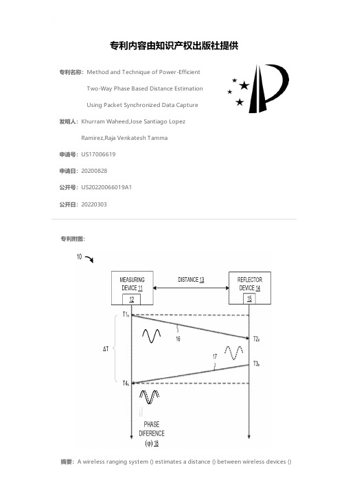
专利名称:Method and Technique of Power-EfficientTwo-Way Phase Based Distance EstimationUsing Packet Synchronized Data Capture发明人:Khurram Waheed,Jose Santiago LopezRamirez,Raja Venkatesh Tamma申请号:US17006619申请日:20200828公开号:US20220066019A1公开日:20220303专利内容由知识产权出版社提供专利附图:摘要:A wireless ranging system () estimates a distance () between wireless devices ()by calibrating the devices through exchanging calibration packets () to adjust transceiver settings for performing phase measurements at the wireless devices, and then transmitting a measurement packet () from a first wireless device to a second wireless device to synchronize the first and second wireless devices and to perform a two-way IQ data capture sequence at different carrier frequencies during processing of the measurement packet so that the first and second wireless devices each measure phase values for each of the plurality of different carrier frequencies, where the phase values at each of the first and second wireless devices are processed to generate a combined phase offset vector which is processed to determine a first estimated distance between the first and second wireless devices.申请人:NXP USA, Inc.地址:Austin TX US国籍:US更多信息请下载全文后查看。
wireless power transfer

Wireless Power TransferIntroductionWireless power transfer (WPT) is a technology that allows electrical energy to be transferred from a power source to an electrical load without the need for a physical connection. It offers several advantages over traditional wired power transfer methods, such as convenience, flexibility, and safety. In this document, we will discuss the working principle, applications, and challenges of wireless power transfer.Working PrincipleWireless power transfer is based on the principle of electromagnetic induction. It involves two main components: a transmitter and a receiver. The transmitter generates an alternating magnetic field, while the receiver converts this magnetic field back into electrical energy.The transmitter consists of a power source, such as a battery or an electrical outlet, and a coil of wire. When an alternating current passes through the coil, it creates a magnetic field around it. This magnetic field can penetrate through the air and reach the receiver.The receiver also contains a coil of wire. When the magnetic field from the transmitter’s coil interacts with the receiver’s coil, it induces a voltage in the receiver’s coil. This voltage can then be used to power electrical devices or charge batteries.Applications of Wireless Power TransferWireless power transfer has various applications across different industries. Some of the common applications include: Consumer ElectronicsWireless charging has become increasingly popular for smartphones, smartwatches, and other portable electronic devices. It eliminates the need for cables and connectors, providing a convenient and clutter-free charging solution.Electric VehiclesWireless power transfer is also being used for charging electric vehicles. Instead of plugging in the vehicle to a charging station, the driver can simply park the vehicle over a wireless charging pad. This enables effortless charging, reduces the wear and tear on physical charging connectors, and enhances the overall user experience.Medical DevicesWPT is widely used in medical devices such as implanted pacemakers and hearing aids. These devices require a reliable and safe power source, and wireless power transfer provides an efficient and convenient solution.Industrial AutomationIn industrial settings, wireless power transfer can be used to power sensors, actuators, and other low-power devices. Thiseliminates the need for batteries or wired connections, simplifying installation and maintenance processes.Challenges and LimitationsWhile wireless power transfer offers numerous advantages, there are also several challenges and limitations that need to be addressed:EfficiencyOne of the main challenges is improving the efficiency of wireless power transfer systems. Due to the air gap between the transmitter and receiver, a significant amount of energy can be lost during the transfer process. Researchers are working on developing more efficient designs and technologies to minimize these losses.RangeThe range of wireless power transfer is typically limited compared to wired power transfer. In most cases, the transmitter and receiver need to be in close proximity for effective power transfer. Extending the range of wireless power transfer systems is an ongoing area of research.InterferenceWireless power transfer systems can be susceptible to interference from other electronic devices or even environmental factors. This interference can affect the efficiency and reliability of the power transfer. Ensuringrobustness and compatibility with other devices is crucial for the widespread adoption of wireless power transfer.SafetySafety is a critical aspect of wireless power transfer, especially when dealing with high power levels. Designing systems that are resistant to electric shock hazards and comply with safety standards is essential to prevent accidents and ensure user safety.ConclusionWireless power transfer is a promising technology that offers numerous benefits in terms of convenience, flexibility, and safety. It has the potential to revolutionize the way we charge our devices, power our vehicles, and even deliver electricity in industrial settings. Although there are challenges and limitations to be overcome, ongoing research and development efforts are pushing the boundaries of wireless power transfer and paving the way for a wire-free future.。
Epson PowerLite 450W 450W超短焦距投影仪说明书

Epson PowerLite®450WMultiMedia projectorLarger-than-life lessons to captivate any class.the epson powerlite 450W ultra-short-throw projector offers amazing widescreen performance, making it easy to create larger-than-life lessons. project 80" images from just 24" away. Save valuable classroom space and avoid shadow interference with this smart presentation tool. ideal for wall-mount installations and use with interactive whiteboards, the powerlite 450W offers innovative communication tools, including a built-in 10 W speaker, closed captioning decoder and the ability to deliver content over the network. With versatile connectivity features and optional wireless capabilities, it offers the ultimate choice in powerful presentation solutions.Larger-than-life, widescreen images — native WXGa resolution (16:10 aspect ratio);ideal for widescreen computers and tablet notebooksSuper bright and colorful —2500 lumens color light output, 2500 lumenswhite light output1Eco features• Designed to be recycled 4• Energy-efficient E-TORL lamp • RoHS compliant• Epson America, Inc. is a SmartWay SM transport partner 5For more information on epson’s environmental programs, go to e-torl lampThe best-selling projectors in the worldepson understands education and has a solution no matter what your teaching scenario. Built withimage quality and reliability in mind, epson projectors enhance communication and inspire collaboration, while offering a low total cost of ownership. From long-throw projectors designed for traditional educational settings to ultra-short-throw and all-in-one solutions built for progressive classrooms, epson has the model made for you.3LCD technology — for quality and color that’s beyond amazingInnovative technology with proven reliability • 3 chips for full-time, vibrant color• 25% less electricity required per lumen of brightness when compared to 1-chip dlp projectors 2• road-tested reliability from a company with over 20 years of experienceEnergy-efficient E-TORL ® lamp, exclusively from Epson• delivers more lumens per watt and lasts up to 3500 hours 3• Minimizes both light diffraction andlight leakage, providing you the ultimate in lamp longevityAmazing light output• 2500 lumens color light output and 2500 lumens white light output 1• High color light output for bright, balanced, colorful images• light output and performance to meet your expectations • White light output that’s measured using ISO 21118 (a more rigid standard than the outdated aNSi lumens rating used by competitive products)High color light output low color light outputactual photographs of images taken from two competing projectors run in default mode. price, resolution and brightness (white light output) are the same for both projectors.Brilliant widescreen performanceWith WXGa resolution (16:10 aspect ratio), the powerlite 450W is ideal for use with the latest-generation widescreen computers and for projecting high-definition content. It gives you:• 30% more image area than a 4:3 image • 10% more image area than a 16:9 imagethe powerlite 450W still allows you to display 4:3 and 16:9 content without losing image quality.800 x 600Meets basic projection needs1024 x 768Ensures sharper detail1280 x 800Offers the highest quality and is ideal for widescreen (16:10 aspect ratio) displayRedGreenBlueScreenLensPrismMirrorLCD chipMirrorDichroic mirrorDichroic mirrorLampMirrorPowerLite 450W features• Larger-than-life, widescreen images • Ultra-short throw distance • Super bright and colorful •Versatile connectivity options • Value-added communication features • USB Plug ’n Play instant setup • PC-free slideshows • Rich, vibrant color and reliable performance • Energy-efficient E-TORL lamp Ultra-short throw projectionuSB plug ’n play instant displaypc-free slideshowsYou asked, we deliveredIncluded wall mount• Makes installation and short-throw operation easier than everValue-added features• Content delivered over the network, via RJ-45, with optional wireless capabilities• Built-in 10 W speaker and microphone inputUSB Plug ’n Play instant setup• No more computer function keys or bulky VGa cables • Just plug in a standard USB cable and instantly project from your pc or Mac ®• Instantly view your images on both the screen and your PC ; one standard uSB cable does it all!Built-in closed captioning• Essential for education — helps meet ada508requirements for students with hearing impairments • Helps save money — no need to pay for an additional decoder and its installation• Effective and easy to use — easily enabled or disabledthrough the projector remote or menuLong throwSignificant reductions in shadow interferenceUltra-short throw6.1"14.0"15.6"Mount includedPackaging SpecificationsPowerLite 450WDimensions 22.8" x 31.3" x 13.3" (W x D x H)Weight 51.2 lbGenuine Epson LampDimensions 6.3" x 5.6" x 5.6" (W x D x H)Weight 0.8 lb Master CartonDimensions 28.4" x 13.1" x 6.8" (W x D x H)Weight 9.7 lbUnits Per Master Carton 10Air Filter SetDimensions 3.9" x 4.9" x 1.2" (W x D x H)Weight 0.1 lb Master CartonDimensions 5.2" x 12.7" x 4.6" (W x D x H)Weight 1.4 lbUnits Per Master Carton 10Dimensions (W x D x H)Including feet: 19.0" x 15.6" x 6.1"Excluding feet: 19.0" x 15.6" x 4.5"Weight: 12.6 lb (without slide plate) 13.8 lb (with slide plate)Remote ControlFeaturesPower, source search, computer, video, USB, LAN, A/V mute, freeze, user, auto, aspect, color mode, page up and down, e-zoom, pointer, help, volume, menu, esc, enter, mouse functions Operating Angle -75 to +15 degrees Right/left: ± 55 degrees Operating Distance 19.7 ft (6 m)Support —The Epson Connection SMPre-sales support U.S. and Canada 800-463-7766Internet website Service ProgramsTwo-year projector limited warranty, Epson Road Service program,Epson PrivateLine ® dedicated toll-free support and 90-day limited lamp warranty What’s In The BoxPower cord, computer cable (VGA),projector remote control, batteries, user manual CD, EMP Monitor CD, Quick Setup Sheet, PrivateLine support card, mount and password protection stickerAccessory Part NumbersWireless LAN module V12H306P11(ELPAP03)Quick Wireless Connection USB Key V12H005M05(ELPAP05)Epson DC-10s document camera ELPDC10S Epson DC-06 document camera V12H321001(ELPDC06)Presentation remote control V12H007TOBDistribution amplifierELPDA01Component-to-VGA video cable ELPKC19S-video cable ELPSV01Kensington security lockELPSL01Projection LensTypeManual focusF-number Focal Length1.804.68 mm Zoom RatioDigital zoom 1.0 – 1.35xOtherDisplay Performance NTSC: 480 lines PAL: 560 lines(Depends on observation of the multi-burst pattern)Input SignalNTSC/NTSC4.43/PAL/M-PAL/N-PAL/ PAL60/SECAM InterfacesComputer/component video:D-sub 15 pin x 2S-video: Mini DIN x 1Composite video: RCA x 1Audio in x 3 (RCA (L&R) x 1, mini stereo x 2)Variable audio out: mini stereo x 1LAN networking: RJ-45 x 1Serial: RS-232c x 1Monitor out: D-sub 15 pin x 1USB Type B x 1 (USB display, mouse, keyboard interface)USB Type A x 1 (USB memory device)Wireless port 802.11 a/b/g (optional module sold separately)Speaker10 W monauralOperating Temperature 41 ˚ to 95 ˚F (5 ˚ to 35 ˚C)Power Supply Voltage 100 – 240 V ±10%, 50/60 Hz Power Consumption 363 WNetwork on: 10 W standby,Network off: 0.3 W standby Direct power on/off Instant off Fan Noise35 dB (Normal Mode)28 dB (ECO Mode)SecurityKensington ®-style lock provision,security anchor bar,password protection functionSpecificationsProjection SystemEpson 3LCD, 3-chip optical engine Projection MethodFront/rear/wall/ceiling mount Driving MethodEpson Poly-silicon TFT Active Matrix Pixel Number1,024,000 dots (1280 x 800) x 3White Light Output 12500 lumens (ISO 21118 Standard)Color Light Output 12500 lumens Aspect Ratio 16:10Native Resolution 1280 x 800 (WXGA)Resize640 x 480 (VGA), 800 x 600 (SVGA), 1024 x 768 (XGA), 1152 x 864 (SXGA1), 1280 x 960 (SXGA2), 1280 x 1024 (SXGA3),1280 x 768 (WXGA60-1), 1360 x 768 (WXGA60-2), 1440 x 900 (WXGA+), 1400 x 1050 (SXGA+), 1600 x 1200 (UXGA), 1680 x 1050 (WSXGA+)Lamp TypeE-TORL 230 W UHE Lamp Life 3Up to 3500 hours (ECO Mode)Up to 2500 hours (Normal Mode)Throw Ratio Range (16:10) 0.37:1 – 0.50:1(4:3) 0.44:1 – 0.59:1(16:9) 0.37:1 – 0.50:1Size (projected distance)16:10 60" – 96" (19" – 30")4:3 55" – 85" (19" – 30")16:9 60" – 93" (19" – 30")Keystone Correction Manual Vertical: ± 50 degrees Plug ’n PlayProjector is Mac ® compatible DVI to VGAUSB Plug ’n Play for Windows ® 2000 or later Contrast Ratio Up to 2000:1Color Reproduction 16.77 million colorsEpson PowerLite ® 450WMultiMedia projectorProduct Name PowerLite 450W Genuine Epson Lamp Air Filter SetProduct Code V11H318020V13H010L57V13H134A27UPC0 10343 87563 00 10343 87574 60 10343 87575 31Light output varies depending on modes (color and white light output). White light output measured using ISO 21118 standard.2Data source: , Jan. 2009. Average of 796 shipping models, for which manufacturers provided lumens and total power data, all resolutions and brightness levels.3Lamp life will vary depending upon mode selected, environmental conditions and usage. Lamp brightness decreases over time.4See our website for convenient and reasonable recycling options at /recycle 5SmartWay is an innovative partnership of the U.S. Environmental Protection Agency that reduces greenhouse gases and other air pollutants and improves fuel efficiency.Epson America, Inc. Epson Canada, Ltd. 3840 Kilroy airport Way, long Beach, ca 90806 3771 Victoria park avenue, toronto, ontario M1W 3Z5 www.epson.caepson, instant off and e-torl are registered trademarks, epson exceed Your Vision is a registered logomark and Better products for a Better Future is a trademark of Seiko epsoncorporation. powerlite and privateline are registered trademarks, duet is a trademark and epson connection is a service mark of epson america, inc. all other product and brand names are trademarks and/or registered trademarks of their respective companies. epson disclaims any and all rights in these marks. cpd-313831 1/10。
- 1、下载文档前请自行甄别文档内容的完整性,平台不提供额外的编辑、内容补充、找答案等附加服务。
- 2、"仅部分预览"的文档,不可在线预览部分如存在完整性等问题,可反馈申请退款(可完整预览的文档不适用该条件!)。
- 3、如文档侵犯您的权益,请联系客服反馈,我们会尽快为您处理(人工客服工作时间:9:00-18:30)。
1INTRODUCTIONCivil structures require a substantial investment of money and effort for their design and construction. As a result, the structural engineering profession holds a strong interest in advancing the understand-ing of structural behavior under external loads to render designs more economical and resilient. To-wards that end, structural monitoring systems can provide measurement of the response of structures under normal operational loads and extreme distur-bances such as earthquakes. Commercial structural monitoring systems have been installed in a large number of structures in the United States, particu-larly those located in zones of high seismic activity. For example, the 2001 California Building Code, modeled after the 1997 Uniform Building Code (UBC), mandates the installation of at least three ac-celerometers in structures greater than ten stories or 5,574 meter square in aggregate floor area (ICBO 2002).Many benefits can be reaped from embedding structural monitoring systems within civil structures. Response measurements can populate databases that would prove valuable to researchers advancing per-formance-based design principles. Response meas-urements can also be employed as input to damage detection methods that identify and locate potential damage in structural systems. In structures con-trolled by actuators, real-time response measure-ments are required by controllers to calculate control forces.Current conventional structural monitoring sys-tems possess three defining characteristics. First, systems employ hub-spoke architectures where sen-sors are connected directly to centralized data serv-ers. Second, processing of raw sensor data is con-ducted at the data server and not at the sensor node. Third, for reliable communication between sensors and the data server, shielded coaxial cables are widely used.Commercial structural monitoring systems possess some inherent limitations that have hindered their adoption. One such limitation of current designs is the saturation limit on the total number of sensing channels permissible. As a result, installations often only employ a handful of sensing channels on the order of 10 to 15 sensors (Celebi 2002). Further-more, the installation of cables in a structure is labo-rious and costly and drives the total cost of monitor-ing systems high (Straser & Kiremidjian 1998). For instance, monitoring systems installed by the United States Geological Survey (USGS) have cost upwards of thousands of dollars on a per channel basis (Celebi 2002).The recent advances in the electronics and com-puter industries have produced a large number of embedded system and information technologies that can be readily adopted for structural monitoring. One technology that should be considered is wireless communications. Wireless communications havePower-efficient wireless structural monitoring with local data processing J. P. Lynch, A. Sundararajan, K. H. Law, A. S. Kiremidjian & E. CarryerThe John Blume Earthquake Engineering Center, Stanford University, Stanford, CA, 94305ABSTRACT: Conventional structural monitoring systems are centralized, employ cables for measurement transfer, and perform all data processing at the centralized server. A major drawback of these systems is their high installation and maintenance costs. To eradicate the need for expensive cable installations, wireless communications is proposed for the transfer of measurements between sensors. In addition, system function-ality is improved by coupling embedded microcontrollers with the sensor for localized interrogation of raw measurements. The design of a wireless sensing unit that has been optimized for structural monitoring is pro-posed. The performance of the sensing unit is validated in the field using the Alamosa Canyon Bridge in southern New Mexico. A statistical time-series damage detection procedure has been embedded in the sens-ing unit to illustrate the energy saved by local data interrogation compared to communication of time-history response records.revolutionized mobile computing by eradicating computers’ dependence on wires for internet connec-tivity. Likewise, wireless modems are proposed for use in structural monitoring to eliminate the need for expensive cable installations. Wireless communica-tions will simplify sensor installations and reduce system costs, thus making the technology more at-tractive to facility owners. Embedded microcontrollers that consume little power for operation are also attractive for adoption. The coupling of computational power with each sen-sor node is proposed as a major paradigm shift in the design of structural monitoring systems. This com-putational power can be harnessed to locally interro-gate raw time-history measurements with analysis results communicated in lieu of time-histories. An additional advantage of the parallel processing of data is that it can potentially provide gains in the overall power efficiency of the entire wireless moni-toring system. This is an important concern when considering batteries as the sole power source of sensor nodes (Wang & Chandrakasan 2002).The design of a wireless sensing unit for struc-tural monitoring applications was first proposed by Straser & Kiremidjian (1998). Subsequent research has extended their work to include sophisticated computational cores that are capable of performing computational tasks associated with system identifi-cation and damage detection (Lynch et al. 2003b). This paper reviews the recent developments in the design of a wireless monitoring system intended for installation in structural systems. First, the design of a low-cost wireless sensing unit capable of autono-mous operation is discussed with key functional components presented. A series of field validation tests are performed on the wireless sensing unit us-ing the Alamosa Canyon Bridge in New Mexico. During these tests, the computational capabilities of the wireless sensing unit are illustrated by the local processing of response measurements for determina-tion of the structural frequency response function. The paper concludes with an analysis of the energy efficiency associated with the local interrogation of time-history data. A statistical time-series damagedetection procedure is executed by the wireless sens-ing unit using data derived from a laboratory test structure to illustrate the energy efficient perform-ance of the unit design.2 HARDWARE DESIGN OF A WIRELESS SENSING UNITThe design of a wireless sensing unit for structuralmonitoring requires a low-cost solution using mini-mal power. Low-power demands is an especially important design constraint since portable batteriesare a likely power source for units installed in re-mote structures such as bridges. In addition, a de-sign comprised of off-the-shelf electrical compo-nents is pursued to keep unit costs low (below $500 per unit) and to provide the luxury of easy hardware upgrades as technology improvements occur.The design of the wireless sensing unit, as pre-sented in Figure 1, can be divided into three func-tional components: sensing interface, computational core, and wireless communication channel. The flow of data in the wireless sensing unit begins at the sensor interface where measurements can be takenfrom various sensing transducers connected to the unit (including accelerometers, strain gages, andanemometers, just to name a few). After collection,the computational core takes control of the data for storage in memory. Based upon the demands of the wireless sensing unit end user, the core is capable of packaging the data for communication or can exe-cute embedded algorithms using the raw measure-ments. 2.1 Sensor interface The sensor interface is designed to accept the outputof both analog and digital sensors regardless of the sensor type. This sensor transparent interface per-mits the use of both traditional structural sensors such as accelerometers but also for novel sensors asthey become available in the future. In total, three channels are provided by the sensor interface to al-low for the simultaneous acquisition of data from multiple sensors. One channel is intended for the collection of data from analog sensor outputs. Thischannel is serviced by a 16-bit analog-to-digital con-verter (Texas Instruments ADS7821) whose maxi-mum sampling rate is 100 kHz. The two remainingchannels are for digital sensors that internally modu-late their output upon square-wave signals. Micro-machined (MEMS) sensors, such as the Analog De-vices ADXL210 accelerometer, can provide digital outputs with resolutions of 14-bits and higher (Ana-log Devices 1999). 2.2 Energy-efficient computational core The computational core, responsible for the man-agement of unit services and for executing embed-Figure 1. Design overview of the wireless sensing unitded engineering analyses, is an important component of the wireless sensing unit design. A large number of microcontrollers that can be used in the core are already commercially available. In choosing an ap-propriate microcontroller, careful attention must be paid to energy consumption characteristics with low power microcontrollers more attractive. A low-power core with sufficient computational capabilities can be attained by employing two microcontrollers. One microcontroller is chosen for the overall opera-tion of the wireless unit while another is chosen to execute embedded engineering analyses. By parti-tioning the functional tasks of the core between two microcontrollers, each can be chosen to better fit their intended roles.The 8-bit Atmel AVR (AT90S8515) microcon-troller is chosen to manage the operation of the wire-less sensing unit. Some of the tasks that the AVR microcontroller will be responsible for include the collection of data from the sensing interface, man-agement of data stored in on-board memory, and the transmission of data through the wireless modem. The Atmel AVR is chosen because it has adequate on-chip resources required to carry out these func-tional tasks and draws little electrical current when active (8 mA at 5 V).The 32-bit Motorola MPC555 microcontroller is selected as the second microcontroller and will be responsible for the execution of embedded algo-rithms. An attractive feature of the MPC555 is that it performs floating point calculations in hardware thereby rendering the microcontroller faster and more power-efficient. Plenty of on-chip memory is available for the storage of executable programs with 448 Kbytes of read only memory (ROM) and 26 Kbytes of random access memory (RAM). When turned on, the MPC555 draws 110 mA at 3.3 V.With the MPC555 consuming more power than the Atmel AVR, the former is normally kept off. Only when the execution of an embedded analysis is required will it be powered by the Atmel AVR. With the Atmel AVR consuming little power and the MPC555 available for performing computationally-intensive tasks, an overall low-power and computa-tionally capable core is attained.To collect long time-history measurement re-cords, an additional 512 Kbytes of external static random access memory (SRAM) is provided. The external SRAM can be read and written by both mi-crocontrollers.2.3Wireless communication channelThe cables of conventional structural monitoring systems will be replaced by low-cost wireless radios that are integrated with each wireless sensing unit. Besides reducing the overall installation costs, wire-less communications facilitate decentralized com-munication architectures such as peer-to-peer com-munication between sensor nodes. For installation in civil structures, the wireless technology chosen must address the needs of a structural monitoring system. In particular, radios must provide node to node ranges of over 150 m and employ spread spec-trum techniques to ensure reliability in the face of channel interference, multi-path reflection, and path loss. Furthermore, wireless communications require adequate penetration characteristics through typical civil engineering materials such as heavily rein-forced concrete (Davidson & Hill 1997).The Proxim RangeLAN2 7911 radio modem is chosen for inclusion with the wireless sensing unit design. Operating on the 2.4 GHz unregulated FCC industrial, scientific and medical (ISM) band, the RangeLAN2 accommodates data rates of 1.6 Mbps. Open space communication ranges of over 300 m can be attained by employing a 1 dBi omni-directional antenna. However, the shielding behav-ior of heavy construction (e.g. concrete) could re-duce the range to approximately 150 m when used on the interior of structures.The power consumption characteristics of the wireless modem are quite high. The RangeLAN2 modem draws 190 mA at 5 V when actively com-municating to the wireless network. When the mo-dem is not needed, its current draw can be reduced to 60 mA by placing it in sleep mode. In contrast to the power requirements of the computational core, the radio represents the greatest demand. This encour-ages the use of the computational core for data inter-rogation in lieu of transmitting raw time-histories2.4Unit fabricationAfter choosing hardware components for the wire-less sensing unit design, they are assembled into a single unit. To achieve compactness of the unit, a two-layer printed circuit board is designed for mounting integrated circuit chips, such as the micro-controllers and their supporting circuitry. Careful at-tention is made in the design of the printed circuit board to limit the electrical noise of the circuit. The RangeLAN2 modem is placed below the circuit board and is attached directly to the Atmel AVR mi-crocontroller through a serial port connection. Whenfully assembled, the wireless sensing unit is only 10Figure 2. Complete wireless sensing unit prototypecm by 10 cm by 3.5 cm. A picture of the completed wireless sensing unit prototype is presented in Figure 2.A number of different power sources, including batteries and building outlets, can be used for power-ing the wireless sensing unit. To date, portable bat-tery packs have been used; various battery types have been tested to assess the expected operational life of the wireless sensing unit. Table 1 summarizes the operational life expectancy of two different 7.5 V battery packs that have been used with the wireless sensing unit. The first is a standard alkaline (Zn/MnO 2) battery and the second is a long duration lithium (Li/FeS 2) battery. The operational times tabulated in Table 1 are estimates based on the engi-neering design charts provided by the battery manu-facturer (Energizer 2003a, b). They represent the expected life of the battery when used continuously until the battery has been fully depleted and do not take into account potential life extensions when the battery is used occasionally. Therefore, longer bat-tery lives are expected when the use of the wireless sensing unit is duty cycled for intermittent collection of ambient structural response measurements.Table 1. Operational life expectancies of battery sourcesStateVoltage L91 7.5V Li/FeS 2 E91 7.5V Zn/MnO 2(mA) (V) (hours) (hours) MPC SleepAVR On/ MPC Sleep54 5 50 30MPC On Active Sleep3 EMBEDDED FIRMWARE DEVELOPMENTEmbedded software, termed firmware, is required forthe operation of the wireless sensing unit. Careful isattention is paid to the design of the unit’s softwarewith development efforts divided between two layersof software abstraction. The first layer of abstractionrepresents software required for operation of thewireless sensing unit’s hardware features includingoperation of the sensor interface, accessing internaland external memory for data storage, and receivingand transmitting data using the wireless modem.This software will be embedded directly within theAtmel AVR microcontroller.The second software layer is intended for engi-neering algorithms that can interrogate measurementdata stored in memory. The functionality of thislayer does not require direct access to the sensingunit’s hardware and is stored in the MotorolaMPC555 microcontroller. However, indirect control of hardware can be gained by the second software layer by invoking code residing in the first layer. A large number of engineering analyses can be embedded in the proposed wireless sensing units. In particular, analyses widely used in system identifica-tion and damage detection have been explored. For example, previous work has investigated embedding fast Fourier transforms (FFT) in the wireless sensing units to derive the frequency response function from raw time-history data. The frequency response func-tion calculated by the wireless sensing unit has been used to estimate the modal frequencies of a labora-tory test structure (Lynch et al. 2002). A damage de-tection algorithm using two-tiered time-series mod-els, as proposed by Sohn et al. (2001), has also been implemented. The wireless sensing unit has success-fully identified damage in structural models using this approach (Lynch et al. 2003a).Current research efforts have explored the embed-ding of compression algorithms for the size reduc-tion of data prior to transmission by the wireless modem. Smaller data packets result in less power consumed by the wireless modem. Both lossless (data integrity guaranteed) and lossy (minor data dis-tortion incurred) data compression algorithms are being considered.4 FIELD VALIDATION ON THE ALAMOSA CANYON BRIDGE In order to validate the fabricated prototype wireless sensing units, numerous validation tests have been performed including instrumentation within labora-tory and field structures. For this study, the wireless sensing units are instrumented within the Alamosa Canyon Bridge located in southern New Mexico. The bridge serves as a convenient structure for in-strumentation because it is located in a sparsely populated area of the state with almost no trafficcrossing it daily. In addition, the bridge has been used in previous system identification studies and itsmodal properties are well documented (Farrar et al.1997).Constructed in 1937, the Alamosa Canyon Bridgeconsists of seven simply supported spans each 15.24m long and 7.32 m wide. Each span is constructedfrom six W30x116 steel girders supporting a 17 cmconcrete deck. The girders transfer traffic loads toconcrete piers located at both ends of the span withstandard rollers serving at the girder-pier interface.A single section of the bridge will be instrumentedwith a network of wireless sensing units. In addi-tion, a commercial structural monitoring system us-ing conventional cables will be installed in parallelto the wireless monitoring system. The commercialmonitoring system chosen is the Dactron Spectra-Book dynamic signal analyzer capable of accommo-dating 8 simultaneous input channels each with a 24-bit analog-to-digital conversion resolution. The Dactron monitoring system will provide a perform-ance baseline to which the wireless monitoring sys-tem can be compared. Figure 3 summarizes the structural details of the instrumented span with sen-sor locations noted as S1 through S7.In this study, accelerometers are chosen as the primary sensing transducer for measurement of structural responses to impulse and traffic loads. Two different accelerometers will be employed with one type used exclusively with the wireless sensing unit and the other with the cable-based monitoring system. The wireless sensing unit has the Crossbow CXL01LF1 accelerometer interfaced. The CXL01LF1 is MEMS-based accelerometer capable of measuring accelerations in a range of 0 to + 1 g bandwidth of 50 Hz. The Piezotronics PCB336 ac-celerometer is used with the cable-based monitoring system and can measure accelerations from 0 to + 4 g with a noise floor of 60 µg. Because the PCB336 is based on an internal piezoelectric element, the ac-celerometer is not capable of sensing steady state ac-celerations; only accelerations in a 1 to 2 kHz band-width can be measured. As shown in Figure 3, the span is instrumented in seven locations with each accelerometer attached by epoxy to the vertical mid-point of the girder web. At each location, the CXL01LF1 and PCB336 accelerometers are mounted adjacent to one another.The objective of the study is to determine the pri-mary modal frequencies of the span. To attain a fre-quency response function representative of the struc-tural transfer function, impulsive loads are delivered to the bridge deck by a modal hammer. After deliv-ering an impact blow to the deck, the wireless and conventional cable monitoring systems simultane-ously record the response of the structure.Figure 4 presents the absolute acceleration time-history response of the span to a modal hammer blow located at the center of the span. The time-history response is acquired by the two systems us-ing accelerometers mounted to the span at sensor lo-cation S3. The wireless sensing unit is commanded to collect data at a sampling rate of 976 Hz while the Dactron system collects data at 320 Hz. In compar-ing the recorded time-history records, strong agree-ment exists in the acceleration responses with ampli-tude peaks aligned along a shared time-axis. Similar findings are found in the time-history records re-corded at different sensor locations to various modal hammer blows. These findings indicate the per-formance of the wireless sensing unit is reliable and accurate when compared to a conventional cable-based monitoring system.Having obtained two time-history records of the same structural response at sensor location S3, fre-quency response functions are calculated from the recorded data. Figure 5 depicts the 0-30 Hz region of frequency response functions (FRF) derived from data recorded by the wireless and Dactron monitor-ing systems. The FRF function corresponding to the response measured by the wireless sensing unit has been calculated using the unit’s computational core where an FFT algorithm has been embedded.In comparing the two frequency response func-tions, strong agreement exists, particularly in the shape and location of their peaks and valleys. There exists a lack of agreement of the frequency response functions at frequencies less than 2 Hz. This is due to the limitations of the PCB336 accelerometerthe Alamosa Canyon Bridge to modal hammer blowsFigure 3. Structural details of the Alamosa Canyon Bridgewhose piezoelectric transduction mechanism is not capable of capturing steady state and low-frequency accelerations. Furthermore the FRF derived from the Dactron system is smoother compared to the one derived from the WiMMS measured data. This can be attributed to two observations. First, over the 0-30 Hz frequency region, the density of points used to define the frequency response functions is six times greater for the Dactron measured data. Second, the lower analog-to-digital conversion resolution of the wireless sensing unit introduces quantization noise that is not introduced by the Dactron data acquisition system.The first three modal frequencies of the instru-mented span of the Alamosa Canyon Bridge can be calculated from the frequency response functions of Figure 5. Table 2 summarizes the modal frequencies determined from data collected by the wireless sens-ing unit at the different sensor locations of the struc-ture. Also tabulated are the modal frequencies cal-culated during a previous system identification study of a different span of the bridge whose structural ge-ometries were nearly the same (Farrar et al. 1997). Variations in the modal frequencies reflect the dras-tic changes in the temperature of the bridge during the testing of the structure.Table 2. Modal frequencies determined by the wireless moni-toring systemMode 1 Mode 2 Mode 3 Location (Hz) (Hz) (Hz)S1 6.7 8.3 11.6 S2 6.8 8.5 11.3 S3 6.7 8.2 11.4 S4 6.7 8.4 11.7 S5 6.9 8.3 11.5 S6 7.0 8.4 11.8 S7 7.0 8.7 11.9Other vibration sources are considered during test-ing of the bridge including a speeding truck drivenacross the bridge and ambient vibrations originatingfrom an adjacent highway bridge carrying interstatetraffic.5ILLUSTRATION OF POWER EFFECIENCYWITH EMBEDDED ALGORITHMSWith the wireless modem consuming large amountsof energy, it is only used when necessary. As a re-sult, for preservation of battery life, the transmissionof raw time-history records should be avoided.Rather, the computational core is used to locallyexecute embedded algorithms that interrogate time-history records with analysis results transmitted inlieu of the time-histories. With computational re-sponsibility assumed by the distributed nodes of thewireless structural monitoring system and unneces-sary use of the wireless channel avoided, tremendousgains are made in the monitoring system’s overallpower efficiency.To illustrate, this study will focus upon the im-plementation of a promising damage detection algo-rithm to assess the amount of power saved by thewireless sensing unit in locally processing raw time-history records in lieu of transmitting those recordsto a centralized data server. It should be noted thatother embedded analyses could have easily beenused to draw similar conclusions.5.1Statistical time-series damage detectionSohn et al. (2001) have proposed applying patternrecognition theory to the problem of structural dam-age detection. The success in applying pattern rec-ognition lies in choosing appropriate performanceindicators that exhibit change to damage. Their ap-proach uses the coefficients of time-series modelsthat have been fit to time-history records as potentialindicators of damage. Previous studies have imple-mented their damage detection method within thewireless sensing unit for the successful identificationof damage in laboratory test structures (Lynch et al.2003a).Assuming the response of a structure to be sta-tionary, an auto-regressive (AR) process model isused to fit discrete response measurements to a set oflinear coefficients weighing past time-historyobservations:∑=−+=piykikyikryby1(1)The response of the structure at sample index, k,as denoted by y k, is a function of p previous observa-tions of the system response, plus, a residual errorterm, r k y. Weights on the previous observations ofy k-i are denoted by the b i coefficients. It is assumedhistory response data at sensor location S3that the residual error of the AR model is influenced by the unknown excitation input to the system. As a result, a second time-series model is chosen to model the relationship between the residual error and the measured response of the system. For this sec-ond model, an auto-regressive with exogenous inputs (ARX) model is chosen:∑∑==−−++=a i bj jk y j k j i k y i k r y y 11εβα (2) A large number of AR-ARX model pairs can be de-rived for an undamaged structure under a variety of operational conditions to populate a database con-sisting of model coefficients (b i DB , αi DB , and βj DB ). This database is important since it provides a statis-tical basis for judging if future models represent sta-tistical outliers that would suggest potential damage. When a time-history response of the structure in an unknown structural state (damaged or undam-aged) is collected, an AR time-series fitting algo-rithm is executed to determine AR coefficients. These coefficients are then used to find the closest AR model match within the database. If the struc-ture is damaged, an AR model fit to time-history data would not be in agreement with the databasemodels corresponding to the undamaged structure. Model agreement, D , can be calculated by determin-ing the Euclidian distance between coefficient vec-tors of the calculated and database AR models. ()∑=−=pi y i DBi b b D 12 (3) After acquiring the closest AR-ARX model pair from the database, the ARX residual error of Equa-tion 2 is determined by the wireless sensing unit us-ing the unknown structural response. If the structure is in a state of damage, the statistics of the ARX model residual, εk y , will vary from the residual error of the ARX model corresponding to the undamagedstructure. In particular, damage can be identified when the ratio of the standard deviation of the model residual error exceeds a threshold value established from good engineering judgment (Sohn et al. 2001): ()()h DB y ≥εσεσ (4)Establishing a threshold, h , that minimizes the num-ber of false-positive and false-negative identifica-tions of damage is necessary for robust damage de-tection.5.2 Energy efficiencies gained by local damage detection For illustration of the energy efficiencies gained by performing the damage detection procedure locally, the energy consumed by the wireless sensing unit to derive the AR model coefficients, as compared to the energy needed to transmit the raw time-history re-cord, will be calculated. The amount of energy con-sumed by the unit is a function of the time required by the MPC555 microcontroller to calculate the co-efficients. To observe the dependency of the energy consumed upon the complexity of the algorithm, the number of data points in the time-history record, N , and the number of AR coefficients, p , will be varied. Calculation of an AR model can be done using a number of different numerical tools. In this study,the Yule-Walker equations are solved using Burg’s method (Press et al. 1992). Burg’s method requires more computational resources compared to other so-lution alternatives such as least-square methods, but exhibits better stability because it avoids matrix in-versions. After calculating the time required by the wireless sensing unit to calculate the AR coefficients, thetimes are used to calculate the total energy con-sumed. Equation 5 presents how the energy con-sumed, E , by the MPC555 microcontroller is calcu-lated using a time-history record of 4,000 points to determine 30 AR coefficients. For this record, thetime taken, t , by the MPC555 to calculate coeffi-cients is approximately 8.35 sec. ()()()J sec A V t i V E REG 031.3351.811.03.3==⋅⋅= (5)In this experiment, the data stored in memory is infloating point form using 4 bytes per data point. Asa result, a 4,000 point time-history record represents16,000 bytes of stored data. To transmit this data us-ing the RangeLAN2 modem, 11 packets are usedeach with an overhead of 14 bytes. In total, 16,154bytes are sent to the wireless channel using the serialinterface between the computational core and the modem. This transfer of data takes 6.73 sec using the modem’s 19,200 bits per second transfer rate.Therefore, the energy consumed by the wireless mo-dem can be determined: ()()()J sec A V t i V E REG 400.673.6190.05==⋅⋅= (6) The energy required by the PowerPC to determine the AR coefficients is approximately 47% of that re-quired to wirelessly transmit the raw time historydata. This serves as illustration of the energy effi-ciencies associated with the local processing of raw time-history data in lieu of its wireless transmission. For this case, a 53% savings in energy is observed. In a similar manner, the time required for records of different lengths and models of varying numbers of coefficients are determined by empirical experi-mentation. Figure 6 presents a summary of the en-ergy consumed by the MPC555 to determine AR co-efficients as a percentage of the energy required for transmission of the data using the wireless modem. As shown, significant gains in energy efficiency of the wireless structural health monitoring system are gained by local processing of measurement data. Itshould be noted that a discontinuity exists in the re-。