C532 如何为仅黑色打印模式进行配置
如何将CAD设置为黑白打印?教你快速设置
如何将CAD设置为黑白打印?教你快速设置
根据工作的需要我们会将CAD文件进行打印,或者是转换,很多的时候我们接触的CAD图纸文件都是彩色的,必要的时候也会需要使用黑白进行打印,这里应该如何进行设置呢?
如果你在工作中有这样的困扰,不妨看看下面的方法吧,其实很简单,只要大家在使用的电脑中下载安装一款迅捷CAD编辑器,就可以进行CAD黑白打印的设置,甚至是CAD 文件的编辑,都是十分轻松的事情,这里就教大家如何进行快速的设置。
第一步:将迅捷CAD编辑器下载安装在电脑上,直接在浏览器中搜索迅捷CAD编辑器关键词进行搜索,也可以进入软件的官网进行相关的操作。
第二步:将安装的软件打开,打开之后我们点击“文件-打开”将需要进行打印的CAD 文件进行打开,接下来继续的点击“文件-打印”
第三步:然后我们进入打印预览,进入之后我们选择“CAD绘图设置”。
然后就可以
看见各种是属性参数的设置,这里取消勾选“彩色打印”。
第四步:之后打印预览显示的就是黑白的CAD文件打印,想要进行打印的纸张大小比例等参数,大家可以选择“绘图设置”进行设置,最后点击打印就可以完成将CAD设置问黑白打印啦。
很简单的步骤,确实十分实用的步骤,希望可以帮助到大家,当然更多的CAD文件添加文字,进行绘图的改写,都是可以使用迅捷CAD编辑器进行编辑的,有需要的小伙伴,下载安装迅捷CAD编辑器就是可以进行操作哦,官网搜索就是可以进行免费的下载安装CAD编辑器哦。
打印机扫描及端口设置方法
打印机扫描设置方法
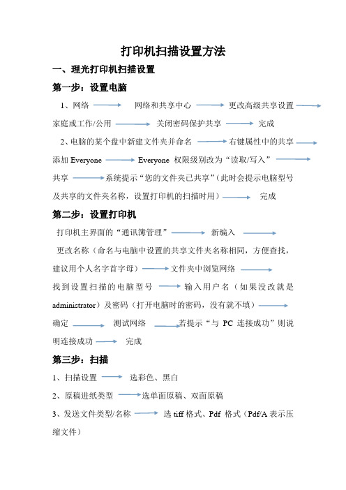
一、理光打印机扫描设置
第一步:设置电脑
1、网络网络和共享中心更改高级共享设置家庭或工作/公用关闭密码保护共享完成
2、电脑的某个盘中新建文件夹并命名右键属性中的共享添加Everyone Everyone 权限级别改为“读取/写入”
共享系统提示“您的文件夹已共享”(此时会提示电脑型号及共享的文件夹名称,设置打印机的扫描时用)完成
第二步:设置打印机
打印机主界面的“通讯簿管理”新编入
更改名称(命名与电脑中设置的共享文件夹名称相同,方便查找,建议用个人名字首字母)文件夹中浏览网络
找到设置扫描的电脑型号输入用户名(如果没改就是administrator)及密码(打开电脑时的密码,没有就不填)
确定测试网络若提示“与PC连接成功”则说明连接成功完成
第三步:扫描
1、扫描设置选彩色、黑白
2、原稿进纸类型选单面原稿、双面原稿
3、发送文件类型/名称选tiff格式、Pdf 格式(Pdf/A表示压缩文件)
4、选择“文件夹”(扫描文件发送处,也就是自己电脑上设置的共享文件夹)按开始键完成
(若是没有装订在一起的多张文件,可放在打印机上盖自动扫描;若是装订的书本则需打开打印机上盖,一张一张手动翻页扫描)
二、惠普打印机扫描设置
1、放入扫描文件
2、电脑打开HP M1530 Scan(装HP打印机驱动时,自动有此软件)
3、选择格式、大小、输出类型、文件类型扫描保存完成
理光打印机端口重设方法
开始所有程序设备和打印机找到打钩的理光打印机选中打印机,鼠标右键打印机属性端口添加端口选择Standard TCP/IP Port 新端口下一步
输入IP地址:192.168.0.200 完成应用确定。
如何配置一台彩色打印机默认为黑白

如何配置一台彩色打印机默认为黑白
如何配置一台彩色打印机,默认为黑白
编辑:oa161办公商城
说明1关闭任何应用程序或应用程序运行,以确保这些设置保存properly.2Move鼠标光标移动到“开始”,单击一次。
进入“控制面板”,带来了一个定制的设置列表。
双击“打印机和传真”,看到所有的当前安装的打印机和传真打印机system.3Select你想正确的图标右击配置为黑色和白色。
一旦你点击右键,你应该看到一个菜单出现。
点击“属性”,调出当前的打印机properties.4Double单击“颜色标签”。
找到的颜色选项“灰度打印”和“彩色打印”。
单击框旁边的“灰度打印”复选标记应该出现在框中一旦点击。
这将告诉打印机只使用黑色墨盒。
点击“应用”,然后单击“确定”。
现在保存设置,打印机将打印在黑色和白色。
爱普生MT532最全的设置文档
EPSONM-T500/BA-T500SETUP MANUALSEIKO EPSON CORPORATIONRev. AHandling GuidelinesWarnings, Cautions, and NotesNotes and precautions in this manual are identified by their level of importance, as defined below.Safety and Handling PrecautionThis section presents important information intended to ensure safe and effective use of this product. Please read this section carefully and store it in an accessible location.IntroductionThe M-T500 is a new standard high-performance thermal printer that can combined with the BA-T500, designed specifically for controlling the M-T500, to create a customized system for the user.This manual describes how to set up the M-T500 and BA-T500 system and provides some important precautions on handling the products.In this manual, the printer is called the M-T500, however the actual products are named according to each specification.The example below shows the relationship between the model name and the specificationExample:M–T5 3 2 A Findicates the M-500 series.indicates the paper width to be used.1:57.5 ± 0.5 mm (2.26 ± 0.02")2:59.5 ± 0.5 mm (2.34 ± 0.02")3:79.5 ± 0.5 mm (3.13 ± 0.02")4:82.5 ± 0.5 mm (3.25 ± 0.02")indicates the type of the paper path.1:Curved path2:Straight pathindicates that the printer has an autocutter.indicates the cutting type.F:Full cut (completely)P:Partial cut (one point left uncut)Cautions1.This document shall apply only to the product(s) identified herein.2.No part of this document may be reproduced, stored in a retrieval system, or transmitted in anyform or by any means, electronic, mechanical, photocopying, recording, or otherwise, without the prior written permission of Seiko Epson Corporation.3.The contents of this document are subject to change without notice. Please contact us for thelatest information.4.While every precaution has been taken in the preparation of this document, Seiko EpsonCorporation assumes no responsibility for errors or omissions.5.Neither Seiko Epson Corporation nor its affiliates shall be liable to the purchaser of this productor third parties for damages, losses, costs, or expenses incurred by the purchaser or third parties as a result of: accident, misuse, or abuse of this product or unauthorized modifications, repairs, or alterations to this product, or (excluding the U.S.) failure to strictly comply with Seiko Epson Corporation's operating and maintenance instructions.6.Seiko Epson Corporation shall not be liable against any damages or problems arising from theuse of any options or any consumable products other than those designated as Original EPSON Products or EPSON Approved Products by Seiko Epson Corporation.Copyright © 1999 Seiko Epson CorporationTable of Contents1. System Overview (1)2. Preparation (2)2.1 Needed Items or Devices (2)2.1.1 Power supply unit (2)2.1.2 Power supply connector cable (3)2.1.3 Interface cable (3)3. Unpacking (4)3.1 M-T500 (4)3.2 BA-T500 (5)4. Parts and Dimensions (6)4.1 M-T500 (6)4.2 BA-T500 (7)5. Notes on Installation (8)5.1 M-T500 (8)5.2 BA-T500 (9)6. Connecting Cables (10)6.1 Connecting the BA-T500 with the Printer FFC (10)6.2 Connecting the BA-T500 with the Power Supply (11)6.3 Connecting the BA-T500 to the Host PC (12)7. Operations (13)7.1 M-T500 (13)7.1.1 Loading Paper (13)7.1.2 Replacing Paper (17)7.1.3 Removing Jammed Paper (17)7.2 BA-T500 (18)7.2.1 Indicators and Button (18)7.2.2 Panel Connector (19)7.2.3 Near-end Sensor Connector (19)8. Self-test (20)9. DIP Switches and Memory Switches (21)9.1 DIP Switches (21)9.1.1 DIP Switch 1 (21)9.1.2 DIP Switch 2 (22)9.2 Memory Switch (23)10. Windows Printer Driver (25)11. Notes on Handling (26)11.1 M-T500 (26)11.1.1 Transport precautions (26)11.1.2 Storage precautions (26)11.1.3 Usage precaution (27)11.1.4 Installation precautions (28)11.1.5 Opening/closing the platen unit (28)11.2 BA-T500 (29)11.2.1 Initial installation (29)11.2.2 Usage precaution (29)12. Troubleshooting (30)A. APPENDIX..............................................................................................................................App.1A.1 General Specifications....................................................................................................App.1A.1.1 M-T500...............................................................................................................App.1A.1.2 BA-T500.............................................................................................................App.1A.2 Options............................................................................................................................App.2A.2.1 PS-170 Power Supply Unit.................................................................................App.2A.2.2 PS-170 connecting connector............................................................................App.3A.3 Cable Signal Connections...............................................................................................App.5A.3.1 Parallel Interface Cable......................................................................................App.5A.3.2 Serial interface connection example..................................................................App.6 A.4 Paper..............................................................................................................................App.8 A.5 Black Mark Sensor Specifications..................................................................................App.9A.5.1 Size and specifications for black mark sensor...................................................App.9 A.6 Cable for Connecting the M-T500 and the BA-T500....................................................App.11 A.7 M-T500 External Dimensions.......................................................................................App.121. System OverviewThe figure below shows the basic system configuration for the M-T500 and the BA-T500.M-T500/BA-T500 Basic System ConfigurationBefore using the M-T500 and BA-T500, you must acquire some of items or devices yourself.Please select them according to your own system configuration. Details are described in Section 2 of this manual.2. Preparation2.1 Needed Items or DevicesThe following items or devices are required to use the M-T500 and the BA-T500.Item Used for Method to getPower supply unit Power supply to the BA-T500.Acquire or make a power supply that meets the specifications as shown in Section 2.1.1. Or, you can purchase the EPSON original power supply PS-170.Power supply connector cable Cable between theexternal power supplyand the BA-T500.Acquire or make a power supply connectorcable that meets the specifications asshown in Section 2.1.2. Or you canpurchase the EPSON original power supplyconnector cable.Interface cable with the host computer Interfaces between thehost computer and theBA-T500.Acquire or make a serial or parallel interfacecable depending on your needs.2.1.1 Power supply unitUse a power supply with the following capacity:Output supply voltage:24 V ± 10%Power consumption:150 W or moreTo prevent the power supply from fire danger, never exceed the voltage above.If you use a power supply with a power consumption of less than 150 W, the print quality may be reduced or the printing speed may become slower.The following power supply also is available from EPSON.Model: PS-170Please contact your dealer to obtain this power supply.2.1.2 Power supply connector cableThe power supply connector cable connects the external power supply unit and the BA-T500.This connector needs to provide the following pins, which are commercially available.•Housing:5195-04 (MOLEX) ..................................... 1 pieces•Terminal:5194 (MOLEX) .......................................... 4 piecesPower supply Connector Pin AssignmentsPin No.Function1GND 224V 324V4GNDThe following connector cable also is available from EPSON.Model: DC-T500 (PS-170 Connecting Cable)Please contact your dealer to obtain this cable.2.1.3 Interface cableOne of these interface cables is necessary, depending on your system.(1) Parallel interface cableThis cable is 36-pin and is commercially available.Refer to Section A.2.1 for pin assignments in detail.(2) RS-232 interface cableThis cable has a 9-pin and female connector on the printer side of RS-232 interfacecable.Refer to Section A.2.2 for pin assignments in detail.12343. Unpacking3.1 M-T500Your printer box should include the items below. If any items are damaged or missing, please contact your dealer for assistance.• M-T500 printer mechanism• FFC cables (connected to the BA-T500; 30-cm length)•21-pin FFC ......................... 1 pieces for the print head •15-pin FFC......................... 1 pieces for the printer mechanism3.2 BA–T500Your BA-T500 box should include the items below.•BA-T500 control board• Hexagonal lock screwYour BA-T500 has inch-type hexagonal lock screws installed. If your interface cable requires millimeter-type screws, replace the inch-type screws with the enclosed millimeter-type screws using a hex screwdriver.GrooveInch screw Millimeter screw(Installed) (Enclosed)4. Parts and Dimensions4.1 M-T500Size126.9 mm (W) × 91.9 mm (D) × 57.5 mm (H) (5 × 3.6 × 2.3”)Weight Approximately 550 g (19.4 oz)Curved path modelStraight path modelFor the details on dimensions of the M-T500, refer to Section A.7, M-T500 External Dimensions.4.2 BA-T500[Units: mm]CN1:Option board connectorCN2:RS-232 connectorCN3:Power supply connectorCN4:Panel connectorCN5:Parallel interface connectorCN6:Print head connectorCN7:Printer mechanism connectorCN8:Near-end sensor connectorCN9:Option board connectorS1:Paper feed buttonD3:Power LEDD5:Paper-end LEDD6:Error LED5. Notes on Installation5.1 M-T500To install the M-T500 into a case, follow the points below:•To avoid deforming the printer when it is installed, the printer should be attached with screwsin the mounting-foot locations (a, b, c, and d) on the printer bottom frame.•It is desirable to keep the area of the case contacting the mounting-foot locations within 0.2mm of the center of the bump. No part of the printer (except the mounting-foot locations)should touch the case.•Be sure not to pinch the lead wires or FPC of each connector, or to damage the wires byc db a•Refer to Section A.7, M-T500 external dimensions for the locations of the mounting feet.5.2 BA-T500To install the BA-T500 board into the case, keep the following points in mind when designing the case.•Make the space 5 mm or more between the top of the electrolytic capacitor on the BA-T500and the case.•Make the space 5 mm or more for the installing feet of the BA-T500.•Set the BA-T500 in the metal case.•Fix connector CN2 to the case.PCB Installation6. Connecting Cables6.1 Connecting the BA-T500 with the Printer FFC(CN7)6.2 Connecting the BA-T500 with the Power SupplyUse the power supply connector cable (see Section 2.1.2) to connect the BA-T500 to the external power supply unit.6.3 Connecting the BA-T500 to the Host PCThrough the serial or the parallel interface as shown in the figure below, the BA-T500 isconnected to the host computer. You need to select one of these interfaces depending on your system.(1) When you use the parallel interfaceConnect the CN5 of the BA-T500 with the parallel interface cable (see Section A.2.1)7. Operations7.1 M-T5007.1.1 Loading PaperFollow the steps below to load the paper.Note:If the paper is not inserted at a right angle, paper jams may occur. In this case, raise the platen lever to open the platen unit, and load the paper properly after removing the paper jam.Correct way of loading paperPlaten-open paper insertion1.Cut the edge of the paper as shown in the figure.2.Turn the platen lever to open the platen unit.3.Be sure to note the correct side for paper insertion, then insert the paper into the paperentrance at a right angle.Platen-closed paper insertion for curved path type4.Pull the edge of the paper out from the paper exit.5.After confirming that the paper is inserted straight, turn the platen lever or push theplaten push plate down to close the platen unit. At this time, make sure that platen unit is closed securely.Paper insertion for straight path printer type (M-T512A/T522A or M-T532A/T542A)Platen-closed paper insertion1.Cut the edge of the paper as shown in the figure in the first page of Section 7.1.1..2.Make sure you have the correct side of the paper to insert; then insert the paper into thepaper entrance at a right angle.Platen-closed paper insertion for a straight path printer typeNote:If the paper is not inserted at a right angle, paper jams may occur. In this case, raise the platen lever to open the platen unit, and load the paper properly after removing the paper jam.Platen-open paper insertionThe paper is normally inserted with the platen closed, but also can be inserted while the platen is open. Refer to “Platen-open paper insertion for curved path type” when youinsert the paper with the platen open.7.1.2 Replacing PaperFollow the steps below to replace the paper.1.Open the platen unit using the platen lever and pull the paper out. The paper can alsobe removed by feeding the paper until it is unloaded from the platen after cutting thepaper at the paper entrance side.2.Load new paper. (See previous section for loading the paper.)7.2 BA-T5007.2.1 Indicators and ButtonThere are three LEDs and one button on the BA-T500.D3D5D6Panel Button and IndicatorsPAPER FEED BUTTON (S1):When this button is pressed once, the printer feeds paper one line.To feed paper continuously, hold down the button.To execute the self-test, hold down the FEED button and then turn onthe printer. (See Section 8, Self-test.)POWER LED (Green):When power is stable, the POWER LED light is green.PAPER OUT LED (Red):When the paper roll end or near-end is detected, the PAPER OUTLED light is red. If the printer is in self-test standby state, the PAPEROUT LED blinks.ERROR LED (Red):When the printer cannot perform printing, the ERROR LED light is redor blinking.1)During the initial setting of the printer after the power is turned onor an interface reset is executed, the ERROR LED light is red for amoment, then turns off automatically.2)When the printer detects the paper roll end, then it stops, and theERROR LED light turns red. In this case, you need to replace thepaper roll with a new one.Blinking:1)When the print head temperature exceeds the maximum level ofthreshold temperature, the ERROR LED blinks.This may occur if high-duty printing is executed for a long period.If the temperature decreases, the ERROR LED stops blinking.Then the remaining printing starts automatically.2)Other problemsTry turning the printer power off and, then turning it back on. Ifthe ERROR LED still blinks, please contact your dealer.7.2.2 Panel ConnectorThe button or LEDs on the BA-T500 can be installed separately through this connector.In this case, connect the signals as follows:23456User side connector type Housing:EHR-06 (JST)Contact:SEH-001T-P0.6 (JST)7.2.3 Near-end Sensor ConnectorIf you install a paper roll near-end sensor, be sure to wire the sensor as shown below. Use the mechanical-contact switch (normal open type, which detects a near-end when the switch is on) for the near-end sensor.Near-end sensor12CN8[BA-T500 side][User side]User side connector type:Housing:IL-S-2S-S2C2-S (JAE)Terminal:IL-S-C2-S-1000 (JAE)The near-end sensor also is available from EPSON.Model: NE-T500Please contact your dealer to obtain this sensor.8. Self-testYou can test the following printer functions by executing the printer self-test.1) The printer self-test function checks the following:•Control circuit functions•Status of the printer mechanism connected to the BA-T500•Print quality•Interface type and its operating condition•Control software version•DIP switch settings•Memory switch settings2)Starting the self-testTo start the self-test on a paper roll, open the platen, and hold down the FEED button; thenturn on the printer. The printer prints the current printer status. (*1)(*1)•Control version•DIP switch settings•Memory switch settings3)Self-test standby stateAfter printing the current printer status, the printer prints the message "Self-test printing.Please press FEED button." The PAPER OUT LED indicator blinks and the printer entersthe standby state for printing the rolling pattern printing. (*2) Press the FEED button to startprinting the rolling pattern.(*2)•A rolling pattern uses only the built-in character set4)Ending the self-testAfter a number of lines are printed, the printer indicates the end of the self-test by printing "***completed ***," initializes, and goes into the standard mode.9. DIP Switches and Memory Switches9.1 DIP SwitchesThe DIP switches are mounted on the BA-T500. The DIP switch number is printed on the board,as shown in the figure below.DSW1DSW2DIP Switch Layout9.1.1 DIP Switch 1DIP Switch 1 (DSW1)SW No.Function ON OFF Factory setting Remark1BM sensor EnabledDisabledOFF 2OFF 3Interface selection Refer to the table below.OFF 4Serial interface handshaking XON/XOFF DTR/DSR OFF Effective only when the serial interface is selected.5Serial interface parity check Yes No OFF Effective only when the serial interface is selected.6Serial interface parity selection EvenOddOFF Effective only when the serial interface is selected.7OFF 8Serial interface baud rate selectionRefer to the table below.OFFEffective only when the serial interface is selected.Interface SelectionSwitch number I/F23Parallel interface (IEEE 1284)OFF OFF Serial interface (RS-232)OFF ON Optional interfaceON ON or OFFBaud Rate SelectionSwitch number BPS: Bits Per SecondTransmission Speed (BPS)784800ON ON 9600OFF ON 19200ON OFF 38400OFFOFF9.1.2 DIP Switch 2DIP Switch 2 (DSW2)SW No.FunctionONOFFFactory settingRemarks1OFF 2Model type selection Refer to the table below for model type selection OFF 3OFF 4Print density selection Refer to the table below for model type selection OFF5Operation mode selection Refer to Table below.OFF 6Factory use OFFFixed to Off.7I/F pin 6 reset signalEnabledDisabledOFFEffective only when the serial interface is selected.8I/F pin 31 reset signal Enabled Disabled OFFEffective only when the parallel interface is selected.Model Type SelectionSwitch Number Model12M-540 (82.5 mm) (3.25”) model (640dots)OFF OFF M-530 (79.5 mm) (3.13”) model (576dots)ON OFF M-520 (60 mm) (2.36”) model (448dots)OFF ON M-510 (58 mm) (2.28”) model (432dots)ONONPrint Density SelectionSwitch Number Level Print Density341Slightly Light ON ON 2NormalOFF OFF 3Slightly dark ON OFF 4DarkOFFONOperation Mode SelectionSwitch NumberOperation mode5Hexadecimal dump ON NormalOFFMemory Switch 8SW No.Function ON (1)OFF (0)FactorysettingRemarksOFF (0)1 2Print control modeRefer to the table below forPrint Control Mode Selection OFF (0)3Backward paper feeding Enabled Disabled OFF (0)(*1) 4Autocutter installation Not installed Installed OFF (0)5Reserved--Fixed to Off OFF (0)6Backward paper feedingamount88 steps108 steps OFF (0)7Reserved--Fixed to Off OFF (0)8Reserved--Fixed to Off OFF (0)Switch NumberDefault for the print control mode12Non-divided energizing mode OFF OFFTwo-part energizing mode ON OFFFour-part energizing mode Don’t care ON*1:This switch can be set to On only when a printer that can feed paper backward is used.(Refer to each printer’s specification for details.)If backward paper feeding is enabled, the following process is executed.•After cutting the paper with the GS V command, backward paper feeding is executed (when the BM sensor is disabled).•The print starting position can be adjusted with GS ( F command to set to the backward direction relative to the cutting position.In this case, the maximum of the correction value to backward is based on the setting with the memory switch 8-6.10. Windows Printer DriverThe specific printer driver (called “EPSON Advance Windows Driver”) for this system with onWindows is available from the EPSON Web site or sales office.1)Applicable OSWindows 95/98, Windows NT4.02)Installation“EPSON Advanced Windows Driver” has the installer software for easy installation.This software automatically recognizes the OS environment, and then starts installation.3)ManualAn online manual (pdf format) for the “Epson Advanced Windows Driver” is includedwith the driver software, and you can view it with the Acrobat reader.11. Notes on Handling11.1 M-T50011.1.1 Transport precautions•When transporting the unit, do not hold it by the motor lead wires or the FFC (especially theFFC terminal).•Avoid severe impact to the printer, such as dropping or bumping it.•Correct way of holding the printer•To avoid static electric damage to the thermal head, do not touch the FFC terminal with yourbare hands. Also, use proper anti-static procedures, such as using anti-static mats andgrounding yourself before handling the printer.•Transport the printer with the platen unit closed.•When shipping the printer, use anti-static packing materials.11.1.2 Storage precautionsPrinter•Do not store the printer in locations subject to high levels of dust or other contamination,direct sunlight, high temperatures, or high humidity.•Before storing the printer for an extended period, remove the printer paper, clean the platenand the thermal head, and close the platen unit after the alcohol evaporates.Printer paper (thermal paper)•Avoid heat, humidity, sunlight and solvents, regardless of whether or not the paper has beenused. (Thermal paper gradually darkens at about 70°C (158°F)•Avoid areas of high temperature the humidity (for example, in winter near a heater, or insummer in a hot room or in direct sunlight). If the paper is stored in direct sunlight,discoloration of both the paper and the printed characters may occur.11.1.3 Usage precautionPrinter•Since the printer contains permanent magnets (in the motor) as well as electromagnets, itshould not be used in areas containing excessive dirt, dust and metallic particles.•Never print without paper installed or the head away from the platen, because the life of thethermal head may be shortened.•Never pull the paper out (forward or backward) with the head down against the platen.•Since the head heating elements and the driver IC are very delicate, avoid touching themwith any metal objects, such as tweezers or screwdrivers.•Since the head area and the motor surface are hot right after printing, never touch them withyour bare hands; wait about 15 minutes for them to cool.•Operate the head-up lever only when required.•Never touch the surface of the head heating elements and the driver IC, as dirt may stick tothem, affecting the head heating elements or causing damage by static electricity.•Before handling the thermal head, ground your properly to avoid static electricity.•Make sure no dust collects on the thermal paper.•Since the printer uses a line thermal print head, condensation must be avoided. Ifcondensation occurs, do not turn on the printer until it has disappeared.•Do not apply excessive pressure to the thermal head connectors. The FFC can bereconnected up to ten times.•Do not apply excessive pressure to the platen lever when opening or closing the platen unitwith the lever.Paper (thermal paper)Use only the recommended thermal paper because thermal papers made with a high ioncontent, such as Na, K and CI, may damage the head heating elements.11.1.4 Installation precautionsWhen installing the printer in your device, avoid areas containing dust, dirt, and metallic particles.11.1.5 Opening/closing the platen unitThe platen unit can be opened and closed using the platen lever (green lever) located on theleft side of the printer. When the platen unit is open, the head separates from the platen,allowing paper to be loaded in the unit.It is also possible to close the unit by pushing down directly on the platen push plate. Pressdown on it until it clicks into place on the frame.Opening/closing the platen unit11.2 BA-T50011.2.1 Initial installationTo avoid electric damage to the electronic parts mounted on the BA-T500, use proper anti-static procedures, such as using anti-static mats and grounding yourself before handling the BA-T500.11.2.2 Usage precaution(1)Since the BA-T500 uses the electronic parts, condensation must be avoided. Ifcondensation occurs, do not turn the power until it has disappeared.(2)To prevent the BA-T500 from allowing foreign objects to fall into it, keep this inconsideration when designing the cover or the board layout.(3)Attach a connector cover to the unused interface connector on the BA-T500.(4)Ensure that the interface cable is securely connected.(5)Never apply voltage that exceeds +27 V to the BA-T500.(6)Do not connect devices out of the specification to the connectors on the BA-T500.(7)Be sure to turn the power off if a DIP switch setting is to be changed.(8)Be sure to turn the power off if a connector is to be connected or disconnected.12. TroubleshootingThis chapter gives solutions to some problems you may have.1) Status monitor cannot operate→Check whether the printer operating mode is set to the ECP mode. If so, change the setting to the bidirectional mode, because some PCs may not work correctly ECP mode.2) Printer does not work→Check the power supply or other cable connections.3) Data cannot be printed correctly→Execute the self-test. If there is no problem, check the serial port setting if you use the serial interface.A. APPENDIXA.1 General SpecificationsA.1.1 M-T500•High-speed printer:150 mm/s (5.9”/second) maximum•High reliability:15 million lines for life and 37 million lines for MCBF.•Platen open mechanism provides easy paper loading, easy removal of jammed paper, andeasy head cleaning.•Can use either 57.5 mm (2.26”), 59.5 mm (2.34”), 79.5 mm (3.13”), or 82.5 mm (1.25”)•A scissors-type autocutter.•Can print on paper thicknesses from 56 to 150 µm (0.0022” to 0.0059”)•Black mark sensor (option).A.1.2 BA-T500•Supported printer:M-T500 series(M-T510/T520/T530/T540)•High-speed printing:150 mm/second (5.9”/second) maximum•Printing of various bar codes:UPC-A, UPC-E, EAN13, EAN8, ITF, CODE39, CODABAR,CODE93, CODE128•Driver:Windows printer driver provided with the status monitor programfor the Windows 95/98, or Windows NT4.0•Control code:Based on ESC/POS®•Interface:Parallel (IEEE 1284), RS-232•Power requirements:24V ± 10%, 150 W or more•Black mark:Preprinted black mark paper can be used with the black marksensor-equipped model.•Logo printing:Can print a logo saved in flash memory•Supported characters:Optionally available for some countriesA-1。
设置默认黑白打印
magicolor1600 设置默认黑白打印
大家都知道mc16xx系列打印机,除了mc1600没有显示屏,其他像mc1650/mc1680/mc1690都有显示屏,可以方便的进行打印机本体的任何操作及设置。
那么magicolor 1600没有显示屏,怎么更改它的“颜色”,设置成默认黑白打印呢?
有以下方法:
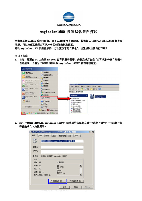
1.首先,需要在PC上安装mc 1600打印机驱动程序。
安装完成后会在“打印机和传真”列表中
自动生成一个名为“KONIC MINOLTA magicolor 1600W”的打印机驱动。
2.选中“KONIC MINOLTA magicolor 1600W”驱动后单击鼠标右键—>选择“属性”—>选择“打
印首选项”。
(如图所示)
3.在选择“打印首选项”之后,画面会转到打印机驱动的“基本”标签—>鼠标选择“质量”标
签(如图)。
4.在“质量”标签中找到“颜色”选项(初始值为“彩色”)(如图所示)。
5.将“颜色”选项设置为“黑白”(如图所示)。
选择“应用”—>“确定”。
这样,将“KONIC MINOLTA magicolor 1600W”设置成默认黑白打印就完成了。
如何设置成纯黑色打印输出

AutoCAD如何设置成纯黑色打印输出一、现象:在AutoCAD应用软件下打印设计图形时,由于AutoCAD文件中不同性质的线条用不同的色彩表示,在黑白颜色打印输出时,不同颜色的线条就被打印出不同深浅的黑色(即不同的灰度级)。
有些颜色不能用纯黑色输出。
二、原因分析:在AutoCAD软件中,图形文件中的彩色线条,它的色彩属性有两种:一种是设计的色彩,即色彩可能代表不同的宽度等属性;一种是通过绘图仪进行打印输出时,用绘图仪不同颜色的笔来打印某种颜色的线条。
例如:在AutoCAD图形中,红色的线条设定为用绘图仪的蓝色笔进行打印输出。
这样,图形中的所有红色线条便被绘图仪用蓝色笔进行打印输出。
对于用打印机输出时,其打印出的颜色,其原理与绘图仪输出是一样的,即:图形中的所有红色线条被打印机打印成蓝色线条。
所以利用这个AutoCAD软件的特点,我们把所有的色彩设置成用黑色(在AutoCAD中,实际上是白色笔号)输出。
三、解决方法:通过AutoCAD实现纯黑色的打印输出1、AutoCAD R14中操作:1.1、打开AutoCAD R14,点击“文件(File)”菜单中的“打印(Print)”菜单,如图下所示。
1.2、选择“画笔安排(Pen Assignments)”按钮,如下图所示。
1.3、选中“笔号(Pen No)” 框中的所有的颜色,然后在“变更设定值(Modif y Values)”将“笔号(Pen)”全部改为“7”,然后点击“确定(OK)”。
如下图所示。
提示:当更改“笔号(PEN No.)”的时候,可以统一把全部的“笔号(Pen No.)”都改成“7”,即都使用黑色笔号输出,但是要重新恢复成原来的值,只能逐一去更改,所以修改之前最好备份记录原来的笔号。
1.4、现在,我们就可以把AutoCAD 的图纸用纯黑色来打印输出了。
2、在AutoCAD 2000、2002、2004操作:2.1、运行AutoCAD,打开要打印的文件。
京瓷FS-C5350DN操作手册
֡ፕ֩
ٍDŽཀৄDžฆஹᆶ၌ࠅິ
ฉ࡛۫ႎ൶๘ु ڢٷ211 ࡽฉ࡛႑တٷေ 11 ୍
Tel:(021)58775366 Fax:(021)58885085
©2011 KYOCERA MITA Corporation ྺٍࠅິฆՔ
؛Ӳ2011.4 ዐࡔᆇຘ302K856070
关于商标
PRESCRIBE 是京瓷株式会社的注册商标。 KPDL 是京瓷公司的商标。 Hewlett-Packard、PCL 及 PJL 是惠普公司的注册商标。Centronics 是 Centronics Data Computer Inc. 的商标。 PostScript 是 Adobe Systems Incorporated 的注册商 标。Macintosh 是苹果电脑公司的注册商标。Microsoft、Windows 及 Windows NT 是微软公司的注册商标。 PowerPC 和 Microdrive 是 IBM 公司的商标。 CompactFlash 是 SanDisk Corporation 的商标。ENERGY STAR 是在美国注册的 标记。所有其他品名及产品名称是其相关公司的注册商标或商标。 本机使用 Wind River Systems 公司的 Tornado™ 实时操作系统及工具开发 而成。 本打印机含有 Monotype Imaging Inc 的 UFST™ 及 MicroType®。
责声明。 2 以二进制形式重新发布必须复制随发布附带的文档与/或其他材料中
的上述版权声明、这份条件清单以及下述免责声明。 3 所有提及本软件功能或使用内容的广告资料必须显示下列声明:
“本 产 品 包 含 由 OpenSSL Project 开 发 应 用 于 OpenSSL Toolkit 的 软 件。(/)”。 4 事先未经书面许可,不准将“OpenSSL Toolkit”和“OpenSSL Project” 名称用于认可或推广由本软件衍生出的产品。 有关书面许可的信息,请联系 openssl-core@。 5 事先未经 OpenSSL Project 书面许可,由本软件衍生出的产品不允许 被称为 “OpenSSL”或在其产品名称中出现 “OpenSSL”字样。
RICOH一体机使用手册
Aficio MPC3501
2
清空设置
智驭办公 还原真彩
开关电源
3 取消/停止
启动
简化显示
精品文档
4
Next…4
简化界面切换
1 全界面 3 简化界面 精品文档
5
Aficio MPC3501
智驭 办公 还原真彩
2 界面切换
Next…5
复印原稿放置
Aficio MPC3501
智驭办公 还原真彩
玻璃台面 请将原稿顶角摆放,复印面
精品文档
23
Aficio MPC3001 智驭办公 还原真彩
Next…23
免费保修电话
理光服务热线:400-888-0022
Aficio MPC3501 智驭办公 还原真彩
➢基本配置 操作界面,显示语言切换,
➢功能简介 功能键,启动键
➢简化界面 简化键, 全屏切换
Aficio MPC3501 界面简介
智驭办公 还原真彩
精品文档
3
Next… 3
操作界面功能
1
复印 文件储存
传真 打印 扫描
打印数据传输 警告 提示: ➢按照你的需要选择相应的功能 ➢数字键盘,可直接输入数字,默认数量为1份
6 按“开始” 键, 发送传真
精品文档
17
Next…17
电子传真发送指南
1 选择文件:
打印 3
2 选择名为“LAN-Fax”的打印机,按确定
Aficio MPC3501 智驭办公 还原真彩
4 发送
键入需要传真的号码(Set as dest. 可添加多个传真号码)
精品文档
18
选择发送(或者发送打印),完成 (注:如需错误报告发送给用户,请提前在MFP 和驱动中设置email server
CAD如何设置黑白打印
CAD如何设置黑白打印
在完成工程制图后,很多22软件的使用者会用各种颜色将设计图中的各项内容加以
区分,使各项内容更直观,二次编辑更容易办到。
但是,有时候打印出来并不需要这种效果,只需要简单的黑白打印即可。
那现在,小编就教大家CAD如何设置黑白打印。
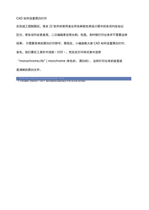
首先,我们要在工具栏中找到〃打印〃,然后在打印样式表中选择
//monochrome.ctb// ( monchrome :单色的,黑白的),这样打印出来的就是就
是清晰的黑白文件。
(F)M IMCD(D)(N)(M) ET00(W)(H)
nr s基况后区哈岛s »▼股a
总Drawl 1 点C:\_\Desktop\CLINIC 3D.dwg
ByLayer
❷出艮气图□□国Q6
一口ByL&yer ▼ -------- ByLayer ▼
\ Xu 。
口厂e 0r.JcG 仔0 ・一
圈口◎含ffl 国
忿Drawing 1 媒G\.M\Desktop\CLINIC- 3D.dwg 4 t> ▼ X
有些使用者会在CAD打印中选择,打印出来不清晰,那是因为他们选择的打印样式选
择是:"grayscale.ctb" , ( grayscale :灰色的),这个是转换成灰色的,由于根是
据颜色亮度转换的,如果是亮色,太亮的话会几乎转换成白色,这样打印出来不清晰
To。
崭新印通喷墨版设定步骤
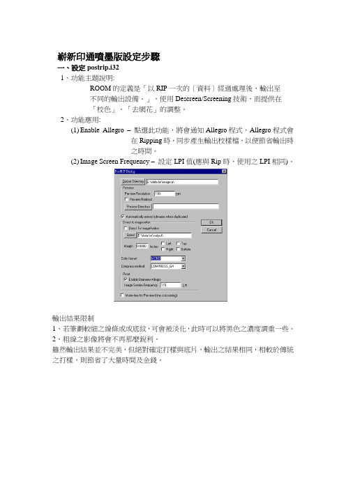
嶄新印通噴墨版設定步驟一、設定postrip.i321、功能主題說明:ROOM的定義是「以RIP一次的〔資料〕經過處理後,輸出至不同的輸出設備。
」,使用Descreen/Screening技術,而提供在「校色」、「去網花」的調整。
2、功能應用:(1)Enable Allegro –點選此功能,將會通知Allegro程式,Allegro程式會在Ripping時,同步產生輸出校樣檔,以便節省輸出時之時間。
(2)Image Screen Frequency –設定LPI值(應與Rip時,使用之LPI相同)。
輸出結果限制1、若筆劃較細之線條或或底紋,可會被淡化,此時可以將黑色之濃度調重一些。
2、粗線之影像將會不再那麼銳利。
雖然輸出結果並不完美,但絕對確定打樣與底片,輸出之結果相同,相較於傳統之打樣,則節省了大量時間及金錢。
二、設定Allegro1、主題說明:節省輸出噴墨印表機時,需產生之校樣檔之時間。
2、應用時機:當需要打樣之稿件可利用「Allegro程式」在Ripping時同步產生「噴墨印表機」,所需要之「校樣檔」,當嶄新落大版完成PL Y檔後,即可以直接輸出,不需在等待產生「校樣檔」。
3、功能介紹:1.1 Polling Directory:指定輪詢目錄,以便取出Ripped後高檔,來完成噴墨印表機所需要之校樣檔。
1.2 Dest. Directory:設定校樣檔存放目錄,以便放置噴墨印表機,所需之校樣檔(可設定此目錄在欲輸出至噴墨印表機之ImageHarbor, 以便節省檔案在網路上傳輸時間)。
1.3 Imghb Directory:實際Imagharbor執行檔所在位置,主要是共用相同校色目錄。
1.4 Calibration name:指定使用之校色檔設定。
1.5 Proof DPI:噴墨印表機輸出之DPI值設定。
1.6 Compression:針對產生噴墨檔時所用之壓縮格式(請選擇G4)。
1.7 Auto start:當作用時,則每當啟動allegro就會作動在start。
佳能25系列中速复印机常用功能使用快速设置操作修改
佳能25系列中速复印机常用功能使用快速设置操作修改佳能中速复印机常用功能使用快速设置操作本操作主要针对25系列,其他系列可以借鉴25系列新机组装完成后的墨粉搅拌工作:在面板上连续按“附加功能键或设置注册键、2、8、附加功能键或设置注册键”四个键进入维修模式,通过方向键逐级选择CLEAR---ENGIN---TNRINST,确定后机器开始搅粉操作,大概需要5分钟,停止后开始其他工作。
不执行这一步打印复印副本将会不完整甚至全白。
IP地址的设置:在控制面板上按附加功能键或设置注册键,选择系统设置,在管理员识别码和系统密码中都输入7654321,按ID登录/注销键登陆,进入后选择网络设置——TCP/IP协议——IPV4,进入后,假如网络连接正常的话会有相应的ip地址子网掩码网关等信息,这时只需点一下DHCP(默认DHCP是开启的,呈黑色),关闭自动分配,使其成白色就行了,也可以手动设置合适的ip地址、子网掩码和网关等信息,然后点完成,关机再开机,这样IP地址设置就完了。
ID卡(身份证)复印功能:在25等系列机器上选择特殊功能,选择ID卡复印,直接下一步下一步到完成,我们在复印第一面的时候,ID卡可放置在顶上A4宽度居中位置再下来一张卡偏下一点的位置,翻转复印第二面的时候,ID卡放置在顶上A4宽度居中位置偏下一点点就可以了,这样复印出的两个图像位置就更靠近,当然也可以放在左上角同一个位置。
熟练使用复印机后亦可使用特殊功能中二合一功能,原稿尺寸选A5R,操作同ID卡类似。
一次最多可放置4张ID卡进行复印。
分套功能:在将几页或更多页文件复印成几份文件时,我们需要使用分套功能,按屏幕上的分页装订处理,选择分套,另外还有个旋转选项,选择后可以达到十字分页或分套,但是要求纸张有横着放,推荐使用多功能托盘,横放入纸张选择A4R。
这样设置后就是一套从纸盒一套从多功能托盘交替出纸,而且十字交叉。
只是复印一套是没有意义的。
考无忧职称计算机题库将配色方案设置为黑色并且在屏幕提示中显示功能说明
考无忧全国职称计算机考试试题解析系列(PowerPoint2007模块)
题目要求:
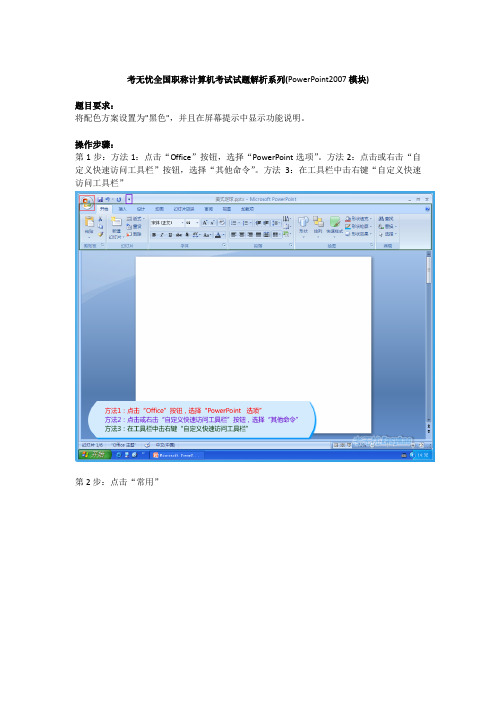
将配色方案设置为"黑色",并且在屏幕提示中显示功能说明。
操作步骤:
第1步:方法1:点击“Office”按钮,选择“PowerPoint选项”。
方法2:点击或右击“自定义快速访问工具栏”按钮,选择“其他命令”。
方法3:在工具栏中击右键“自定义快速访问工具栏”
第2步:点击“常用”
第3步:点击“配色方案”下拉按钮,选择“黑色”
第4步:点击“屏幕提示样式”下拉按钮,选择“在屏幕提示中显示功能说明”
第5步:点击“确定”
第6步:答题完成
以上内容由考无忧职称计算机考试官网提供:。
Epson532打印机使用说明书
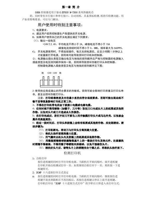
第一章简介80K6控制器是用于驱动EPSON M-T500系列热敏机芯的。
同时带有并行接口和串行接口,自动切纸,具备黑标检测,纸将尽检测功能,用户如有特殊要求,可以专门解决。
用户使用时特别注意事项:1:电源要求:A:建议用户采用控制器生产商提供的开关电源。
B:如果用户使用自己的开关电源应满足下列要求:(1):输出一组电压+24V±2.4V:平均电流不得小于2A,峰值电流不得小于15A峰值电流持续时间不得小于0。
8MS,频率最大为560PPS。
C:开关电源使用时,不得连续操作,每次关闭电源后,应至少间隔1分钟以上才能重新打开电源,否则有可能导致损坏打印机和控制器。
D:电源输出插头类型及输出电压与地线的排列顺序应严格与控制器的电源输入插座类型及电压排列顺序保持一致,否则将导致损坏热敏打印头和控制器。
控制器电源输入插座类型及电压与地线的排列顺序见下图:地 +24V +24V 地2:使用供应商或确认的符合要求的热敏纸,否则可能会影响打印质量及打印头寿命,甚至会损坏热敏打印头。
注意:打印纸卷密度及内径最小直径应符合误差要求,否则可能出现走纸不畅不直等现象影响打印机正常工作。
3:不得在打印机带电状态下拔接口电缆或电源电缆。
4:任何时候不得用硬物(如镊子,刀片等)取切刀口内或头片上的纸屑或其他附作物,以免对头片或刀片造成永久性损伤。
5:在打印完成后,若打开切刀不要马上用手触摸打印头片或马达外壳,以免被金属外壳高温烫伤。
6:经过一段时间后,打印头和胶棍上会粘有纸屑或其他附作物,应定期清洁。
清洁步骤为:(1):打印机断电,将切刀与打印头分离到最大位置。
(2):将机头抬杆前推到最大位置。
(3):用气囊吹去机头内及胶棍上的纸屑或其他附作物。
(4):用微湿酒精棉球轻擦陶瓷基片上的一整条打印头发热元件。
注意擦洗时酒精不得滴淌,不得用镊子等硬物夹持棉球,以免不慎碰伤头片。
(5):清洗好头片后,请等头片上的酒精完全干燥之后,再将机头抬杆放下。
黑白打印时纯黑的解决方法

– 提示 若要通过一次操作对多个项进行相同的更改,请按住 Shift,同时 单击每个项将它们全部选中。松开 Shift 键,右键单击选中项中的任意一 个,然后单击快捷菜单上的所需选项。
• 对象在两种模式下的显示外观
对象
灰度 纯黑白
文本
黑色
黑色
文本阴影
灰度
隐藏
阳文
灰度
隐藏
填充
灰度
白色
框架
黑色
黑色
图案填充
灰度
白色
线条
黑色
ห้องสมุดไป่ตู้
黑色
对象阴影
灰度
黑色
位图
灰度
灰度
解决方法:
• 通过实践,笔者终于找到了造成这种结果 的原因了。
• 具体方法:1、进入幻灯片母板视图
• 2、进入母版的灰度视图
• 3、在灰度视图工具栏中单击设置-灰度逆转, 以取消灰度逆转。
• 经过以上步骤,就可以正常灰度打印了。 • 大家可以以此PPT练习一下。
颜色、灰度和黑白视图下打印的区 别
• 更改视图和打印模式 • 在“视图”菜单上,指向“颜色/灰度”,然后单击“灰度”或“纯黑
白”。 • 单击“文件”菜单上的“打印”,然后在“打印”对话框中,单击
“颜色/灰度”列表中的相应打印模式。 • 更改各个对象的外观 • 当在灰度视图或纯黑白视图中查看演示文稿时,请执行下列操作:
解析北洋打印机黑标纸的打印设置

解析北洋打印机黑标纸的打印设置
解析北洋打印机黑标纸的打印设置
方法一、通过驱动来进行设置
在驱动里面主要是设置纸张类型,将纸类型设置为黑标纸,该设置方法是在打印的时候设置的,而不是直接在驱动里面设置的!
方法二:通过打印机测纸
校验一下黑标(校验之前要按楼下(上)所说的`那样设置感应类型):打印机处于关闭状态—> 放入黑标记标签—> 同时按下【进纸】、【暂停】、【取消】按键—> 开机上电—>待只有【进纸】、【暂停】灯亮时松手—> 打印机处于暂停状态—> 按一下【暂停】按键—> 启动校验—> 校验成功。
通过以上两种方法就可以解决北洋打印机打印黑标的问题,或是以上两种方法组合起来使用!如果还未解决你的问题,应该是黑标传感器有问题,这样可以联系你的设备供应商来解决!。
MG2580S打印黑白彩色设置教程

MG2580S打印黑白彩色设置教程
1、在打印设置当中选择打印机的属性,在属性里面的快速设置当中可以看到有灰度打印可以选择,选择灰度打印之后打印文档就会出现但出来的是黑白颜色,但是灰度打印是消耗所有颜色的墨水的打印。
2、选择黑白打印,仅选择使用黑色墨盒的黑白打印,此时继续选择属性当中的维护选项,里面会出现墨盒设置的选项,点开之后选择仅黑色墨盒的选项,这样就会默认设置在打印A4的文档时,选在黑色
墨盒来打印,就不会出现所有颜色的墨水同时消耗的情况。
另外需要注意的是每一次开关机时,墨盒中的墨水就会出现流动的情况,这是因为每一次开关机墨盒中的水流动是为了防止墨盒堵塞的情况出现。
如何设置复印明暗度(SL-M2876HN,SL-M2676FH)
Last Update date : 2013.06.14
如果原件包含模糊标记和深色图像,您可以调节亮度,使复印件易于阅读。
请按照以下步骤操作:
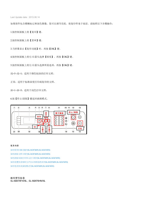
1.按控制面板上的【复印】键。
2.按控制面板上的【菜单】键。
3.当屏幕显示【复印功能】时,再按【OK】键。
4.按控制面板上的左/右箭头选择【暗度】,再按【OK】键。
5.按控制面板上的左/右箭头选择所需选项,再按【OK】键。
浅+5~浅+1:适用于颜色较深的打印文档。
正常:适用于标准深度打印或复印的文档。
深+1~深+5:适用于浅色打印文档。
6.按【停止/清除】键返回就绪模式。
更多内容
如何使用扫描功能?(SL-M2876HN,SL-M2676FH)
如何清除文档卡纸?(SL-M2876HN,SL-M2676FH)
如何清除双面打印单元区卡纸?(SL-M2876HN,SL-M2676FH)
如何设置传真响铃几声以后再转接传真?(SL-M2876HN,SL-M2676FH)
如何更改传真接收模式?(SL-M2876HN,SL-M2676FH)
相关型号信息
SL-M2676FH/XIL , SL-M2876HN/XIL。
- 1、下载文档前请自行甄别文档内容的完整性,平台不提供额外的编辑、内容补充、找答案等附加服务。
- 2、"仅部分预览"的文档,不可在线预览部分如存在完整性等问题,可反馈申请退款(可完整预览的文档不适用该条件!)。
- 3、如文档侵犯您的权益,请联系客服反馈,我们会尽快为您处理(人工客服工作时间:9:00-18:30)。
如果准备长期只使用黑色鼓粉进行打印,则完成下面的为"仅黑色打印模式"配置打印机和移除彩色消耗品。
这样能防止相应的鼓粉盒(青色、品红色和黄色)以及光电辊(感光鼓)部件受到过多的磨损。
注意:将光电辊(感光鼓)部件保存在清洁、阴凉并且干燥的地方,使它们不被接触或刮擦。
将鼓粉盒与光电辊(感光鼓)部件保存在一起。
使光电辊(感光鼓)部件和鼓粉盒随时可用。
1. 为"仅黑色打印"模式配置打印机:
完成下列说明步骤,在从打印机中移除所有彩色消耗品之前设置"仅黑色打印"模式。
1)关闭打印机电源。
2)按住<右>键和<选择>键并打开打印机电源。
3)出现时钟后松开按钮。
CONFIG MENU(配置菜单)出现在显示屏的第一行。
4)按<下>键直到出现Black Only Mode(仅黑色模式),然后按<选择>键。
5)按<上>键直到出现On(开),然后按<选择>键。
出现Submitting Selection(正在
提交选择)消息。
6)按<下>键直到出现Exit Config Menus(退出配置菜单),然后按<选择>键。
短暂出现Resetting the Printer(正在复位打印机),接着是时钟。
然后出现Remove all color supplies(移除所有彩色消耗品),按照下列说明完成移除彩色消耗品。
2. 移除彩色消耗品:
警告:不要触摸光电辊部件上发亮的光电鼓。
1)抓住把手。
2)完全打开上部盖门。
抓住内部盖门的手柄并拉动它以打开内部和下部盖门。
轻轻降低
下部盖门。
现在可以看到光电辊部件。
3)抓住光电辊部件右边的旋钮并向上提以释放光电辊部件,然后用手柄抬起光电辊部
件。
左边的图示显示如何移除其中一个部件的详情,但如右图所示,必须移除所有三个彩色光电辊部件。
4)用包装材料(随替换光电辊部件附带的护板和袋子)来包裹它们。
如果这些项目没有
从被原始包装材料保留下来,则用纸包好每个部件并用包装带封上,但不要将包装带粘贴在发亮的光电鼓上。
5) 将光电辊部件放入随替换部件附带的箱子中。
如果箱子不可用,则用一个空的纸张包装箱代替
6)合上箱子以保护光电辊部件不被暴露在光线中。
7) 抓住图示中细节放大区所示的黄色鼓粉盒上的小手柄。
轻轻向上提起它,然后笔直拉出。
如图示中的主要部分显示,用同样的方法移除品红色和青色鼓粉盒。
8)将鼓粉盒放入任何可用的箱子中。
9) 关闭下部盖门。
这将关闭内部盖门。
10) 关闭上部盖门。
3. 恢复为"彩色打印模式"需要配置打印机并重新安装消耗品:
要返回到彩色打印,请完成下列步骤。
1)关闭打印机电源。
2)按住<右>键和<选择>键并打开打印机电源。
3) 出现时钟后松开按钮。
CONFIG MENU(配置菜单)出现在显示屏的第一行。
下列消息单独出现以作为装回光电辊部件和彩色鼓粉盒的提示。
84 Cyan PC Unit missing
(84 缺少青色光电辊部件)
84 Magenta PC Unit missing
(84 缺少品红色光电辊部件)
84 Yellow PC Unit missing
(84 缺少黄色光电辊部件)
31 Missing or defective Cyan cartridge
(31 青色鼓粉盒缺少或有故障)
31 Missing or defective Magenta cartridge
(31 品红色鼓粉盒缺少或有故障)
31 Missing or defective Yellow cartridge
(31 黄色鼓粉盒缺少或有故障)
当保存在箱子中的光电辊部件被装回到打印机中时,检查光电辊部件透明端上的彩色鼓粉残留物。
残留的彩色鼓粉应该与打印机内传输带上的彩色标签相匹配
4)按<下>键直到出现Black Only Mode(仅黑色模式),然后按<选择>键
5) 按<下>键直到出现Off(关),然后按<选择>键。
出现Submitting Selection(正在提交选择)消息。
6) 按<下>键直到出现Exit Config Menu(退出配置菜单),然后按<选择>键来完成操作。