Fracture behavior of silicon nitride ceramics subjected to hypervelocity impact
单晶硅表面等离子体基离子注入碳纳米薄膜的摩擦学特性

单晶硅表面等离子体基离子注入碳纳米薄膜的摩擦学特性IntroductionSingle-crystal silicon is a widely used material in various technological applications due to its desirable mechanical properties. However, its poor tribological behavior under sliding friction hinders its widespread use. Surface modification techniques such as ion implantation have been applied to enhance its tribological behavior. In this study, we investigated the frictional characteristics of carbon nanofilm implanted on a single-crystal silicon surface by plasma-based ion implantation.Experimental MethodsThe experiments were conducted using a plasma-based ion implantation system. The single-crystal silicon samples were cleaned and then implanted with carbon ions with varying energies and doses. The surface morphology and chemical composition of the implanted samples were characterized using scanning electron microscopy (SEM) and X-ray photoelectron spectroscopy (XPS). The tribological properties of the implanted samples were evaluated by performing friction and wear tests using a ball-on-disk tribometer under dry sliding conditions.Results and DiscussionThe SEM images showed that the implanted samples exhibited a rougher surface compared to the unimplanted ones. The XPS analysis confirmed the presence of carbon on the implanted samples. The friction and wear tests revealed that the implantedsamples exhibited reduced friction coefficients and wear rates compared to the unimplanted samples. The reduced friction was attributed to the formation of a carbon-rich layer on the surface of the implanted samples, which acted as a solid lubricant during sliding. The reduced wear rate was attributed to the increased surface hardness of the implanted samples due to carbon ion implantation.ConclusionThe plasma-based ion implantation technique was successfully used to implant carbon ions on the single-crystal silicon surface. The implanted samples exhibited enhanced tribological behavior, including reduced friction coefficients and wear rates, compared to the unimplanted ones. The improved tribological behavior was attributed to the formation of a carbon-rich layer on the surface and the increased surface hardness due to ion implantation. We conclude that plasma-based ion implantation is an effective surface modification technique for improving the tribological behavior of single-crystal silicon.Furthermore, the specific implantation parameters used in this study, i.e., energy and dose, can be optimized to achieve even better tribological properties. For example, increasing the energy of the implanted ions can result in a deeper implantation and hence a thicker carbon-rich layer on the surface. Similarly, increasing the dose can result in a higher concentration of carbon atoms on the surface, which can lead to further reduction in friction and wear.The use of ion implantation for surface modification has several advantages over other traditional techniques such as coating orsurface texturing. Unlike coatings, ion implantation does not introduce a separate layer on the surface, which can delaminate or wear off over time. In contrast, implanted atoms become part of the substrate material, resulting in a more durable modification. Additionally, the surface texturing technique relies on creating grooves or patterns on the surface, which may not be applicable or effective for all materials or applications.In conclusion, the plasma-based ion implantation technique has been shown to be a promising surface modification technique for enhancing the tribological behavior of single-crystal silicon. This technique has the potential to be applied to other materials and can be optimized for specific applications. Future work can focus on optimizing the implantation parameters, investigating the long-term durability of the implanted surfaces, and exploring the applications of this technique in different technological fields.In addition to silicon, plasma-based ion implantation has been applied to a wide range of materials such as metals, polymers, ceramics, and semiconductors to modify their surface properties for various applications. For example, ion implantation has been used to improve the wear resistance and corrosion resistance of stainless steel, increase the hardness and scratch resistance of polymeric materials, and enhance the adhesion and surface energy of ceramics.Moreover, ion implantation can also be used to tailor the surface properties of materials for specific applications in microelectronics, optoelectronics, and biomedicine. In microelectronics, ion implantation is commonly used to modify the electrical properties of semiconductors such as silicon and gallium arsenide for devicefabrication. In optoelectronics, ion implantation can be used to create waveguides or modify the refractive index of optical materials for photonic devices. In biomedicine, ion implantation can be employed to modify the surface chemistry and topography of implant materials to enhance their biocompatibility and reduce the risk of rejection.In conclusion, plasma-based ion implantation provides a versatile and effective surface modification technique for various materials and applications. Its benefits include improving wear resistance, corrosion resistance, hardness, scratch resistance, adhesion, surface energy, and biocompatibility, among others. The technique can be optimized for specific applications and has potential in a wide range of technological fields. Future research should focus on further understanding the fundamental mechanisms of ion implantation and developing new implantation techniques to address emerging needs in different industries.One area where plasma-based ion implantation has shown potential is in the development of new types of functional coatings. Functional coatings are thin layers of material applied to surfaces in order to impart specific properties such as increased durability, improved friction, or enhanced thermal insulation. Plasma-based ion implantation can be used to create such coatings through a process known as ion beam assisted deposition.Ion beam assisted deposition involves bombarding a surface with high-energy ions while simultaneously depositing a thin film of material onto it. This bombardment modifies the surface properties of the material, allowing the deposited film to adhere more strongly and exhibit improved functional properties.One example of a functional coating that can be created through ion beam assisted deposition is a superhydrophobic coating. Superhydrophobic coatings are highly water-repellent, and can be used in applications such as self-cleaning surfaces, anti-fogging coatings, and water-resistant textiles. By using plasma-based ion implantation to modify the surface properties of a material, it is possible to create a highly rough surface with a variety of different structures that can prevent water from adhering to it.Another area where plasma-based ion implantation has shown promise is in the development of advanced energy materials. By modifying the surface properties of materials such as silicon, lithium, and aluminum, it is possible to create materials with improved energy storage properties. For example, by using ion implantation to create a highly porous silicon surface, researchers have been able to create silicon anodes for lithium-ion batteries with significantly improved performance.In conclusion, plasma-based ion implantation is a versatile technique with promising applications in a variety of fields. By modifying the surface properties of materials, it is possible to create coatings with improved functional properties and advanced energy materials with improved performance. Continued research in this area has the potential to lead to the development of new materials and technologies with a wide range of practical applications.In addition to functional coatings and energy materials, plasma-based ion implantation has also shown potential for use in the biomedical field. By modifying the surface properties of medical implants, it may be possible to improve biocompatibilityand reduce the risk of rejection or infection. For example, an ion-implanted titanium surface could have improved osseointegration and reduce implant failure rates.Furthermore, plasma-based ion implantation can also be used in the field of microelectronics to improve device performance. By modifying the surface properties of electronic components, it is possible to improve their conductivity and reduce power consumption. This can lead to smaller, more efficient devices that have better battery life and can be used in a wider range of applications.Finally, plasma-based ion implantation has potential in the field of environmental science. By modifying the surface properties of materials such as membranes and filters, it is possible to create materials with improved filtration properties. This can lead to more efficient water and air filtration systems that have a smaller environmental footprint.Overall, plasma-based ion implantation is a promising technology that has the potential to unlock new innovations in a wide range of fields. Continued research and development will be needed to fully understand its capabilities and limitations, but the potential benefits make it an exciting area to watch in the coming years.。
电石炉取样条件下氮化硅陶瓷穿透器受力特性有限元模拟
第43卷第3期2024年3月硅㊀酸㊀盐㊀通㊀报BULLETIN OF THE CHINESE CERAMIC SOCIETY Vol.43㊀No.3March,2024电石炉取样条件下氮化硅陶瓷穿透器受力特性有限元模拟赵㊀晴1,潘江如2,毛㊀昀2,徐媛媛2,郭鸿鑫1(1.新疆农业大学交通与物流工程学院,乌鲁木齐㊀830052;2.新疆工程学院控制工程学院,乌鲁木齐㊀830023)摘要:为研究高温情况下力学性能对氮化硅陶瓷穿透器形变量的影响,本文对电石取料现场所用穿透器使用SolidWorks 软件进行建模,在Ansys 软件的Workbench 模块进行耦合和仿真模拟,分析氮化硅陶瓷穿透器在不同力学性能下的变形情况㊂结果表明,25ħ时氮化硅陶瓷穿透器最高形变量为3.12mm,变化率为0.7%㊂随着温度升高,氮化硅陶瓷穿透器形变量呈降低趋势,1800ħ时最高形变量为2.95mm,变化率为0.6%㊂数值模拟结果表明使用氮化硅陶瓷作为穿透器是可行的,可完成电石炉取料作业㊂关键词:氮化硅陶瓷;熔融态电石;力学性能;SolidWorks 建模;嵌入式分析中图分类号:TQ161;TG174㊀㊀文献标志码:A ㊀㊀文章编号:1001-1625(2024)03-1078-09Finite Element Simulation of Stress Characteristics of Silicon Nitride Ceramic Penetrator under Calcium Carbide Furnace Sampling ConditionsZHAO Qing 1,PAN Jiangru 2,MAO Yun 2,XU Yuanyuan 2,GUO Hongxin 1(1.College of Transportation and Logistics Engineering,Xinjiang Agricultural University,Urumqi 830052,China;2.Department of Control Engineering,Xinjiang Institute of Technology,Urumqi 830023,China)Abstract :In order to study the influences of mechanical properties on deformation of silicon nitride ceramic penetrator at high temperature,this paper modeled the penetrator which served as calcium carbide reclaiming by using SolidWorks software,coupled and simulated it in Workbench module of Ansys software to analyze the deformation condition of silicon nitride material under different mechanical properties.The results show that the maximum deformation variable of silicon nitride ceramic penetrator at 25ħis 3.12mm,and the change rate is 0.7%.With the increase of temperature,the deformation of silicon ceramic nitride penetrator decreases.At 1800ħ,the maximum deformation is 2.95mm,and the change rate is 0.6%.The numerical simulation results show that it is feasible to use silicon nitride ceramics as penetrator,which can complete the reclaiming operation of calcium carbide furnace.Key words :silicon nitride ceramics;molten calcium carbide;mechanical property;SolidWorks modeling;embedded analysis 收稿日期:2023-09-04;修订日期:2023-11-03作者简介:赵㊀晴(1999 ),女,硕士研究生㊂主要从事高性能陶瓷力学特性的研究㊂E-mail:q2570212990@通信作者:潘江如,博士,教授㊂E-mail:pjr1978@ 0㊀引㊀言电石作为制作乙炔气体的主要原材料,在有机化合物合成方面具有较强应用价值㊂电石出炉指高温熔融态电石(1700~2100ħ)经电石炉眼流出的过程[1]㊂电石生产制造环境复杂,电石炉内温度高达1800ħ,取料时穿透器会暴露在高温环境中㊂现行穿透器以石墨㊁合金钢以及高纯铜材料为主㊂石墨高温稳定性较好,能够在高温环境下长时间使用,但相对脆弱,易受到机械应力的破坏,消耗量较大;合金钢具有较高的强度和硬度,能够承受较大的机械应力,但高温稳定性较差,易出现脆化现象,不能长时间用于高温环㊀第3期赵㊀晴等:电石炉取样条件下氮化硅陶瓷穿透器受力特性有限元模拟1079境;高纯铜能够高效地传导电流,但易受氧化和腐蚀㊂穿透器对材料的耐高温性㊁抗腐蚀性㊁导热性以及机械强度要求较高㊂穿透器在操作过程中易受高温影响,并需承受操作过程中的压力和负荷以防止在使用过程中裂变,因此需要选择高温稳定性好㊁机械强度高㊁导热性良好的材料,以保证穿透器在服役过程中可以抵抗化学物质腐蚀和介质侵蚀㊂β相氮化硅的本征热导率为200~320W/(m㊃K),β-Si3N4沿a轴的热导率为170W/(m㊃K),沿c轴的热导率为450W/(m㊃K)㊂王文雪等[2]以α-Si3N4粉为原料㊁纳米级Y2O3和Al2O3为烧结助剂,采用气压烧结工艺制备氮化硅陶瓷,当烧结温度为1750ħ㊁烧结助剂含量为8%(质量分数)时,能够得到相对密度大于98%㊁维氏硬度为1540kg/mm2㊁断裂韧性为6.3MPa㊃m1/2㊁压缩强度为288MPa的氮化硅陶瓷㊂武振飞等[3]以Y2O3和MgAl2O4为烧结助剂制备氮化硅陶瓷,当烧结温度为1600ħ㊁保温时间为4h㊁烧结助剂含量为12.5%(质量分数)㊁Y2O3和MgAl2O4质量比为1ʒ1时,生产的氮化硅陶瓷综合性能最好,显气孔率为0.21%,相对密度为98.10%,抗弯强度为598MPa,维氏硬度为15.55GPa㊂研究[4]表明氮化硅陶瓷具有较强的共价键,抵抗冷热冲击能力较强,在空气中加热到1000ħ以上后,经急冷再快速加热,也不会碎裂㊂α-Si3N4较β-Si3N4具有更高的自由能(在25ħ下约为30kJ/mol),1300ħ时Si3N4会发生αңβ相变㊂本试验在电石取料时使用直径为180mm㊁长为450mm的氮化硅陶瓷棒作为穿透电石炉的穿透器,采用数值模拟的方法研究穿透器在穿透高温密封用电石时的形变量,探究陶瓷棒能否穿透电石炉密封用电石并使炉内高温电石液顺利流出㊂1㊀仿真计算模型本次仿真过程分为:1)模型建造及有限元划分;2)流固耦合分析,熔融态电石对氮化硅陶瓷穿透器温度的影响;3)热固耦合分析,研究氮化硅陶瓷在高温情况下的形变量并输出数值㊂实际生产模型如图1所示,氮化硅陶瓷穿透器相关参数见表1,密封用电石相关参数见表2㊂生产整体架构由电石炉体㊁炉体保护圈㊁氮化硅陶瓷穿透器㊁引流槽㊁电石炉底座㊁电石锅组成,总称为电石生产源㊂高温熔融态电石液烧制成功后在电石炉体内暂存,炉内温度为1800ħ㊂取液前期由氮化硅陶瓷穿透器击穿密封所用电石,熔融态电石经引流槽流入电石锅内㊂图1㊀电石生产示意图Fig.1㊀Schematic diagram of calcium carbide production随着温度升高,氮化硅陶瓷的密度㊁弹性模量㊁泊松比㊁各向异性热导率等减小,其中,各向异性热导率变化直接影响穿透器形变量㊂查阅文献[5-10]可知,氮化硅热导率沿a轴与c轴呈递减趋势,如图2所示㊂本文所用材料借鉴文献[5]所给出的具体表征数据,对氮化硅穿透器施加700N,即2.8ˑ10-3MPa压力,分析不同温度下热导率㊁密度㊁弹性模量㊁泊松比㊁压缩屈服强度以及形变量的变化规律㊂1080㊀陶㊀瓷硅酸盐通报㊀㊀㊀㊀㊀㊀第43卷表1㊀25ħ时氮化硅陶瓷穿透器参数Table1㊀Parameters of silicon nitride ceramic penetrator at25ħTesting item Data Test equipment Test criteria Average bending strength/MPa917INSTRON-5566GB/T6569 2006 Weibull modulus14.9INSTRON-5566GB/T6569 2006 Vickers hardness/GPa1446INSTRON-2100B GB/T16534 2006 Fracture toughness/(MPa㊃m1/2) 6.13INSTRON-2100B GB/T16534 2006 Compressive strength/MPa3777INSTRON-5592GB/T8489 2006 Elastic modulus/MPa306Crindo Sonic MK7JC/T2172 2013 Poisson ratio0.291Crindo Sonic MK7JC/T2172 2013 Average coefficient of linear expansion(25~500ħ)/(10-6ħ-1) 2.62NETZSCH TMA403F3GB/T16535 2008 Temperature transfer coefficient(25ħ)/(mm2㊃s-1)9.658Laser-flash apparatus LFA467GJB1201.1 91图2㊀热导率非线性变化曲线[5-10]Fig.2㊀Nonlinear variation curves of thermal conductivity[5-10]表2㊀密封用电石参数Table2㊀Calcium carbide parameters for sealingTesting item DataDensity/(g㊃cm-3) 2.22Elastic modulus/MPa 3.5Poisson ratio0.35Bulk modulus/Pa 3.89ˑ106Shear modulus/Pa 1.3ˑ106Thermal conductivity/(W㊃m-1㊃K-1) 2.22㊀耦合分析2.1㊀嵌入式分析在力学分析中,稳态热源优于瞬态热源的主要原因是稳态热源具备持续且恒定的热能输出能力,能够提供持久的热量;瞬态热源产生的热量会出现强烈的波动,连续性差,导致其难以被精确地预测和控制㊂瞬态结构优于稳态结构的主要原因在于其能够承受更大的动力荷载㊂静态结构主要受到静止负载的影响,而瞬态结构则需要考虑动态荷载的影响,这包括来自外部力量的瞬时冲击和振动㊂随着温度升高,氮化硅陶瓷性能下降,同时试验中所施加的负载是动力载荷,因此使用稳态热源与瞬态结构分析的结果更符合实际情况㊂利用SolidWorks绘图软件进行三维模型绘制,导入Workbench耦合分析场,将稳态热源的结论嵌入到瞬态结构中,利用嵌入式分析方法对氮化硅陶瓷穿透器在不同力学性能下的形变量进行数值模拟㊂图3为嵌入式分析过程㊂在热源分布不明确的情况下,嵌入式分析方法可以精确地得出氮化硅陶瓷穿透器的形变结果㊂考虑到氮化硅陶瓷对温度的依赖性和动载荷的影响,此方法能够模拟密封用电石被击穿的情况,并提供较为准确和专业的分析㊂第3期赵㊀晴等:电石炉取样条件下氮化硅陶瓷穿透器受力特性有限元模拟1081㊀图3㊀嵌入式分析过程Fig.3㊀Embedded analysis process 2.2㊀流固耦合流固耦合方式以双向流固耦合和单向流固耦合为主㊂图4为双向流固耦合示意图,主要利用对偶迭代的时间步长与结构场对应压力数据传递进行计算㊂图5为单向流固耦合示意图㊂首先,执行流场的计算,其次将不同时刻的空气流场及其对应的结构场荷载直接传递至结构场,进行精确的受力分析[11]㊂此方法的优势在于能够有效节约计算时间,提高计算速度㊂熔融态电石流出过程中没有回流现象,结构场并不会因流场变化而发生改变,因此本文使用单向流固耦合㊂图4㊀双向流固耦合示意图Fig.4㊀Schematic diagram of two-way fluid-solidcoupling 图5㊀单向流固耦合示意图Fig.5㊀Schematic diagram of unidirectional fluid-solid coupling 为研究超高温对氮化硅陶瓷本身的腐蚀性,需研究氮化硅陶瓷穿透器将高温熔融态电石引出后的流速大小㊂液体流速通过K-Omega 湍流模型计算,湍流动能k 见式(1),湍流耗散率ω见式(2)㊂∂(ρ-㊃k )∂t +∂(ρ-㊃k ㊃u i )∂x i =∂∂x jΓk ∂k ∂x j ()+G k -Y k (1)∂(ρ-㊃ω)∂t +∂(ρ-㊃ω㊃u i )∂x i =∂∂x j Γk ∂ω∂x j ()+G ω-Y ω(2)其中Γk =μ+μt σk Γω=μ+μt σωìîíïïïï(3)μt =α㊃ρk ω(4)1082㊀陶㊀瓷硅酸盐通报㊀㊀㊀㊀㊀㊀第43卷G k =μt ㊃S 2G ω=α㊃ωk ㊃G k {(5)式中:Гk 为湍流扩散项,Γω为ω的扩散率,Y k 和Y ω为可压缩修正项,σk 和σω为常数,S 为表面张力系数,α为修正系数,μ为黏滞性系数,μt 为涡黏性系数,ρ-为流体体积分布的平均密度,G k 为平均速度梯度所造成的紊动能项,G ω为电湍流耗散率,t 为时间,i ㊁j 分别代表不同方向,u i 为速度分量㊂计算结果如图6㊁7所示,由图6迭代可看出,约90步迭代后计算结果收敛㊂图7为流出速度二维图㊂由图7可以看出,液体流速变化不大,液体中心流速较周围快,约为4m /s,熔融态电石与氮化硅陶瓷穿透器没有相互影响㊂图6㊀流出速度迭代示意图Fig.6㊀Iyeration diagram of outflowvelocity 图7㊀流出速度二维图Fig.7㊀Two-dimensional display of outflow velocity 2.3㊀热固耦合热传递可分为热传导㊁热对流㊁热辐射三种基本方式,本文根据有限元基本理论给出稳态发热-导热问题的微分方程,根据氮化硅陶瓷穿透器物理特性建立相应模型后赋值,并根据现场环境进行了载荷添加,在数次迭代过程中输出结果㊂在稳态分析理论中,认为任意节点的温度保持恒定,其对应的平衡方程如式(6)所示㊂([K ]+[S ]+[R ]){T }=[P ]+[N ](6)式中:{T }为节点温度向量,[K ]为导热系数矩阵,[S ]为对流系数矩阵,[R ]为辐射率矩阵,[P ]为所加的线性热载荷,[N ]为与温度有关的非线性热载荷[12]㊂钻孔过程中,由于材料紧密结合,故本仿真过程中忽略材料接触热阻,根据傅里叶定律和能量守恒定律,结构体内部某点处的温度变化规律可用式(7)所示㊂ρC p ∂T ∂t =σ∂2T ∂t 2+σ∂2T ∂y 2+σ∂2T ∂z 2(7)式中:T 为传热体某一点的温度,t 为时间,ρ为材料的密度,C p 为材料的等压热容,σ为材料的导热系数,y ㊁z分别代表不同方向㊂2.3.1㊀对流换热对流换热问题的数学描述主要包含对流换热微分方程及定解的条件,对流换热微分方程包含质量守恒㊁动量守恒及能量守恒三大守恒定律表达式[13]㊂质量守恒方程如式(8)所示㊂∂u ∂x +∂u ∂y =0(8)动量守恒方程如式(9)㊁(10)所示㊂ρ∂u ∂τ+∂u ∂x +∂u ∂y ()=F x -∂p ∂x +v ∂2u ∂x 2+∂2u ∂y 2()(9)第3期赵㊀晴等:电石炉取样条件下氮化硅陶瓷穿透器受力特性有限元模拟1083㊀ρ∂v ∂τ+∂v ∂x +∂v ∂y ()=F y -∂p ∂x +v ∂2v ∂x 2+∂2v ∂y 2()(10)能量守恒方程如式(11)所示㊂∂t ∂τ+u ∂t ∂x +v ∂t ∂y =σρC p ∂2t ∂x 2+∂2t ∂y 2()(11)式中:F x ㊁F y 分别为体积力在x ㊁y 方向的分量,v 为流体的动力黏度[13],τ为液体表面应力,u 为流速,C p 为恒压热容,ρ为密度,x ㊁y 分别代表不同方向㊂3㊀结果与讨论3.1㊀耦合结果设置炉体内部温度为1800ħ,外部温度为25ħ,对流换热系数为1ˑ10-4W /(mm 2㊃ħ)㊂炉内温度分布如图8所示㊂温度分布由内至外逐层递减,最高温度为1800ħ,最低温度为27.851ħ㊂对炉内温度分布进行数值分析,从炉内开始,以炉体厚度为横坐标,温度为纵坐标,使用非线性曲线拟合,拟合结果如图9所示㊂图8㊀电石炉内壁温度分布Fig.8㊀Temperature distribution on inner wall of calcium carbidefurnace 图9㊀炉体温度拟合曲线Fig.9㊀Furnace body temperature fitting curve 从图9中可以看出,随着电石炉厚度增加,温度下降,厚度每增加30mm,平均温度降低约200ħ㊂下降梯度拟合曲线近似为一次函数,可表达为y =y 0+A ˑsin(pi ˑ(x -x c )/c )(12)式中:y 0㊁A ㊁x c ㊁c 均为函数拟合过程中所产生的参数,y 0=-2924.404ʃ20791.18,x c =-15263.03ʃ38555.12,c =16009.82ʃ41679.02,A =33696.69ʃ88929.44㊂所流出熔融态电石温度对氮化硅穿透器温度的影响如图10所示㊂由图10可看出,随着熔融态电石流出时间的增加,氮化硅穿透器温度随x 轴正方向温度逐步增加,并于18s 后趋于稳定㊂该稳定时间有利于对氮化硅穿透器受热时间进行准确定义并通过进一步计算得出受热与受力状态下氮化硅穿透器的形变量㊂3.2㊀形变量仿真结果氮化硅与氧气反应生成二氧化硅能够阻止氮化硅的进一步氧化,氮化硅在1400ħ高温环境中依然可以保持原本的硬度㊁强度,且受热后不会融化,1900ħ高温环境中才会分解,因此氮化硅在高温情况下受力后形变量近似相等㊂仿真结果中氮化硅陶瓷穿透器整体未出现裂痕,氮化硅陶瓷可作为高温环境下的可靠材料㊂结合图2可知下降曲线图像为非线性递减凹函数,仿真过程中采取图2曲线取点方式进行模拟㊂图11为氮化硅陶瓷穿透器各参数随温度的变化曲线㊂由图11可以看出,氮化硅的密度㊁弹性模量㊁泊松比㊁各向异性㊁热导率等性质随着温度上升而下降,下降趋势趋近于线性递减曲线㊂最高形变量㊁最低形变量及平均形变量均随温度增高而降低,下降趋势平缓㊂其中25ħ时最高形变量为3.12mm,最低形变量为2.88mm;1084㊀陶㊀瓷硅酸盐通报㊀㊀㊀㊀㊀㊀第43卷925ħ时最高形变量为3.02mm,最低形变量为1.6mm;1800ħ时最高形变量为2.95mm占穿透器整体长度的0.6%,最低形变量为0.64mm占穿透器整体长度的0.15%㊂图10㊀熔融态电石温度对氮化硅陶瓷穿透器温度分布的影响Fig.10㊀Effect of molten calcium carbide temperature on temperature distribution of silicon nitride ceramic penetrator㊀第3期赵㊀晴等:电石炉取样条件下氮化硅陶瓷穿透器受力特性有限元模拟1085图11㊀氮化硅陶瓷穿透器各参数随温度的变化曲线Fig.11㊀Curves of various parameters of silicon nitride ceramic penetrator changing with temperature 图12为不同温度下氮化硅陶瓷穿透器形变量㊂由图12可以看出,1800ħ时受力面形变量相对于接触面要更大,形变量沿x轴正方向逐渐减小㊂25ħ时整体形变量沿z轴正方向递增㊂图12㊀不同温度下氮化硅陶瓷穿透器形变量(单位:mm)Fig.12㊀Deformation of silicon nitride ceramic penetrator at different temperatures(unit:mm)4㊀结㊀论1)当炉内温度为1800ħ㊁外部温度为25ħ㊁对流换热系数为1ˑ10-4W/(mm2㊃ħ)时,对穿透器施以700N,即2.8ˑ10-3MPa压力后,氮化硅陶瓷穿透器可以抵御电石取料过程中的高温,最高形变量为2.95mm,变化率为0.6%㊂2)熔融态电石流速变化可以判定其是否会对氮化硅陶瓷穿透器造成影响㊂当电石炉眼被穿透器击穿,熔融态电石以4m/s的速度流出㊂熔融态电石与氮化硅陶瓷穿透器之间不会相互作用,氮化硅穿透器性能在该条件下趋于稳定㊂3)随着炉体厚度增加,电石炉体内部至炉体外部温度逐渐降低,厚度每增加30mm,平均温度降低约200ħ㊂4)氮化硅陶瓷穿透器自身温度受熔融态电石流出的影响,随着时间增加,穿透器温度上升,上升过程约为18s,18s后穿透器温度趋于稳定㊂5)在温度为25~1800ħ时,穿透器形变量不会发生改性,因此,高温条件下氮化硅陶瓷可作为电石炉取料的穿透器㊂参考文献[1]㊀张阳光.电石出炉机器人自动烧眼控制方法研究[D].哈尔滨:哈尔滨工业大学,2017.1086㊀陶㊀瓷硅酸盐通报㊀㊀㊀㊀㊀㊀第43卷ZHANG Y G.Research on automatic eye burning control method of calcium carbide discharging robot[D].Harbin:Harbin Institute of Technology,2017(in Chinese).[2]㊀王文雪,张㊀晶,颜家森,等.烧结助剂含量对氮化硅陶瓷球致密化和力学性能的影响[J].轴承,2021(4):23-27.WANG W X,ZHANG J,YAN J S,et al.Effect of sintering aids content on densification and mechanical properties of silicon nitride ceramic balls[J].Bearing,2021(4):23-27(in Chinese).[3]㊀武振飞,王跃超,陆丽芳,等.无压烧结氮化硅陶瓷的物理性能研究[J].硅酸盐通报,2022,41(5):1782-1787.WU Z F,WANG Y C,LU L F,et al.Physical properties of silicon nitride ceramics by pressureless sintering[J].Bulletin of the Chinese Ceramic Society,2022,41(5):1782-1787(in Chinese).[4]㊀DONG X J,WU J Q,YU H L,et al.Additive manufacturing of silicon nitride ceramics:a review of advances and perspectives[J].InternationalJournal of Applied Ceramic Technology,2022,19(6):2929-2949.[5]㊀ZHOU H,FENG T L.Theoretical upper limits of the thermal conductivity of Si3N4[J].Applied Physics Letters,2023,122(18):182203.[6]㊀ZHOU Y,HYUGA H,KUSANO D,et al.A tough silicon nitride ceramic with high thermal conductivity[J].Advanced Materials,2011,23(39):4563-4567.[7]㊀ZHU X W,SAKKA Y,ZHOU Y,et al.A strategy for fabricating textured silicon nitride with enhanced thermal conductivity[J].Journal of theEuropean Ceramic Society,2014,34(10):2585-2589.[8]㊀YANG C P,YE F,MA J,et parative study of fluoride and non-fluoride additives in high thermal conductive silicon nitride ceramicsfabricated by spark plasma sintering and post-sintering heat treatment[J].Ceramics International,2018,44(18):23202-23207. [9]㊀WATARI K,HIRAO K,BRITO M E,et al.Hot isostatic pressing to increase thermal conductivity of Si3N4ceramics[J].Journal of MaterialsResearch,1999,14(15):1538-1541.[10]㊀KITAYAMA M,HIRAO K,WATARI K,et al.Thermal conductivity ofβ-Si3N4:III,effect of rare-earth(RE=La,Nd,Gd,Y,Yb,and Sc)oxide additives[J].Journal of the American Ceramic Society,2004,84(2):353-58.[11]㊀刘迎宾,李㊀卓,江晓瑞.基于Ansys-Workbench EPKM点火过程流固耦合仿真分析[J].固体火箭技术,2022,45(2):200-206.LIU Y B,LI Z,JIANG X R.Simulation analysis of fluid-structure interaction in EPKM ignition process based on Ansys-Workbench[J].Journal of Solid Rocket Technology,2022,45(2):200-206(in Chinese).[12]㊀刘玉明.星敏感器瞬态热分析研究[D].成都:中国科学院研究生院(光电技术研究所),2015.LIU Y M.Study on transient thermal analysis of star sensor[D].Chengdu:Institute of Optics and Electronics,Chinese Academy of Sciences, 2015(in Chinese).[13]㊀顾恩洋,周常飞.采煤机导向滑靴温度场仿真分析[J].煤矿机电,2017(6):16-19.GU E Y,ZHOU C F.Simulation analysis of temperature field on shearer guiding shoe[J].Colliery Mechanical&Electrical Technology, 2017(6):16-19(in Chinese).。
SiC与耐热钢在高温真空中的界面反应机制研究

第42卷第6期2023年6月硅㊀酸㊀盐㊀通㊀报BULLETIN OF THE CHINESE CERAMIC SOCIETY Vol.42㊀No.6June,2023SiC 与耐热钢在高温真空中的界面反应机制研究谢莹莹1,陈㊀毛1,宋子杰1,范冰冰1,张㊀锐1,2,陈勇强1(1.郑州大学材料科学与工程学院,郑州㊀450001;2.洛阳理工学院材料科学与工程学院,洛阳㊀471023)摘要:碳化硅陶瓷可用作镁冶炼还原钢罐的内衬㊂在真空和1200ħ条件下,通过扩散偶试验,对SiC 与耐热钢的界面反应进行了系统研究㊂结果表明,在反应初期,界面反应的主要产物为金属硅化物和石墨,其中分布在界面的片状石墨阻碍了界面反应㊂由于界面上低熔点硅镍化合物的熔化,片状石墨在Ni 的催化作用下转变为纤维状石墨,失去了对碳化硅的保护作用㊂界面反应由固-固反应转变为固-液反应,界面反应过程加快,加速了钢对碳化硅的侵蚀㊂与耐热钢相比,SiC 与纯铁的界面反应速率明显降低,金属熔化所需温度也显著升高㊂减少耐热钢中的Ni 含量,可以有效阻止耐热钢和SiC 之间的反应㊂关键词:SiC;耐热钢;界面;石墨;固相反应中图分类号:TQ174㊀㊀文献标志码:A ㊀㊀文章编号:1001-1625(2023)06-2161-11Interfacial Reaction Mechanism of Silicon Carbide and Heat Resistant Steel in High-Temperature VacuumXIE Yingying 1,CHEN Mao 1,SONG Zijie 1,FAN Bingbing 1,ZHANG Rui 1,2,CHEN Yongqiang 1(1.School of Materials Science and Engineering,Zhengzhou University,Zhengzhou 450001,China;2.School of Materials Science and Engineering,Luoyang Institute of Science and Technology,Luoyang 471023,China)Abstract :Silicon carbide (SiC)ceramics can be used as inner lining of reduction tank for magnesium smelting.The interfacial reaction between SiC and heat resistant steel was systematically investigated by diffusion couple experiment under vacuum and 1200ħ.The results show that at the early stage of reaction,the main products of interfacial reaction are metal silicide and graphite,and the lamellar graphite distributing at the interface hinders the interfacial reaction.However,due to the melting of silicon-nickel compounds with low melting point at interface,the lamellar graphite is transformed into fibrous graphite under the catalysis of Ni,losing its protective effect on silicon carbide.In addition,the interface reaction changes from solid-solid reaction to solid-liquid reaction,and the interfacial reaction process is accelerated,which accelerates the corrosion of silicon carbide by pared with heat resistant steel,the interfacial reaction rate between SiC and pure iron is obviously decreased,and the temperature required for the reaction is obviously increased.Reducing Ni content in heat resistant steel can effectively prevent the reaction between heat resistant steel and SiC.Key words :SiC;heat resistant steel;interfacial;graphite;solid phase reaction收稿日期:2023-02-23;修订日期:2023-03-27基金项目:国家自然科学基金青年项目(52202072)作者简介:谢莹莹(2000 ),女㊂主要从事冶金用耐火材料方面的研究㊂E-mail:2428230514@通信作者:陈勇强,博士,讲师㊂E-mail:chenyq@ 0㊀引㊀言碳化硅(SiC)陶瓷具有高强度㊁高硬度㊁耐磨损㊁耐氧化和良好的高温力学性能等诸多特性,在碳化硅基电子器件的金属化和高温航空航天技术中有着重要应用[1-2]㊂然而,碳化硅陶瓷存在脆性较大㊁难加工和高孔隙率等缺陷,应用范围受到限购[3-5]㊂目前,SiC 与金属通常被复合成复合材料,从而改变了单一陶瓷或单一金属材料应用的局限性,扩大了应用范围[6-7]㊂但是,各组分在复合材料中无论如何连接和重新组合,总会有一定的界面存在㊂因此,SiC 和金属材料的界面结构和反应对碳化硅/金属复合材料的性能和应用起着2162㊀陶㊀瓷硅酸盐通报㊀㊀㊀㊀㊀㊀第42卷决定性作用[8-9]㊂在皮江法炼镁过程中,镁在1200ħ㊁10Pa条件下被还原[10-11]㊂因此,耐热钢在工业生产中被用作还原罐㊂金属材料本身存在局限性,在高温下会发生蠕变,导致罐体坍塌而无法继续使用㊂因为还原罐的坍塌和变形,一些机械化的操作设备无法使用,只能依靠人工取罐和排渣㊂由Cr24Ni7S制成的传统还原罐寿命约为60天,使用寿命短,这不仅提高了冶炼成本,还严重影响了生产效率㊂有学者提出,在金属罐内安装陶瓷内衬来支撑金属罐,可以延缓金属罐在高温下的蠕变行为㊂据估计,该方法可将还原罐的使用寿命提高三倍以上,但目前该设计尚未应用到实际生产中㊂考虑到常用陶瓷的高温强度㊁高温氧化性能㊁抗热震性能以及生产成本等因素,碳化硅陶瓷可以用作镁冶炼还原罐的衬里材料㊂然而,作为还原罐内衬材料的SiC与Cr24Ni7S在1200ħ㊁10Pa条件下的物理化学相互作用尚未被研究㊂目前的研究主要集中于液态金属对SiC复合材料的侵蚀[12-14],而对于固态金属对SiC的侵蚀机理研究较少[15-16]㊂其他研究学者[17-20]也重点研究SiC与Fe㊁Ti㊁Ni㊁Cr等金属的扩散偶之间的界面反应,而对SiC 与合金之间的高温反应,特别是对真空条件下的高温反应研究较少[20-22]㊂本文将Cr24Ni7S和SiC组成的扩散偶置于模拟皮江法炼镁的环境中(1200ħ㊁10Pa),详细研究了SiC/钢界面反应和侵蚀过程㊂对不同时间段的样品进行采样和分析,并利用XRD㊁SEM㊁TEM/EDS等方法对其微观结构进行了详细表征和分析,以期为碳化硅陶瓷衬里在皮江法炼镁中的应用提供理论指导㊂1㊀实㊀验1.1㊀材料及样本制备试验中使用的碳化硅(华盛碳化硅有限公司)的主要成分是SiC和SiO2㊂碳化硅陶瓷的主要物理性能如表1所示㊂ZG30Cr24Ni7钢(Cr24Ni7S)的材质与常规镁冶炼还原罐相同,主要成分如表2所示㊂另外,选择纯度为99.9%的铁进行对照试验㊂表1㊀碳化硅陶瓷的物理特性Table1㊀Physical properties of SiC ceramicProperty IndexFlexural strengthσ/MPa522ʃ5Bulk density/(g㊃cm-3) 2.98ʃ0.14Apparent porosity/%14.01ʃ0.21Diffusivity(25ħ)/(mm2㊃s-1) 4.8ʃ0.3Thermal conductivity(25ħ)/(W㊃m-1㊃K-1)18.3ʃ4.8Thermal expansion coefficient(25ħ)/% 5.6ˑ10-6表2㊀ZG30Cr24Ni7钢的主要成分Table2㊀Main composition of ZG30Cr24Ni7steelComposition Cr Ni C Si Mn P N S Mass fraction/%23.76 6.910.29 1.03 1.960.040.120.03首先将SiC和Cr24Ni7S钢分别加工成20mmˑ20mmˑ5mm和5mmˑ5mmˑ5mm的试样㊂通过粗磨㊁细磨去除表面氧化皮,再经过金相抛光得到表面光滑的样品㊂最后将SiC和金属样品的抛光表面拼接在一起,形成紧密接触的扩散偶㊂1.2㊀试验设备和程序利用可视化高温相变仪(TA-16A,CTJZH,中国)观察SiC与金属界面反应过程中的形态变化㊂该设备主体为卧式管式炉,由硅钼棒加热,最高加热温度为1600ħ,且配有真空和气体保护系统,样品可在真空环境或大气保护下进行测试㊂此外,该设备配备了专业的摄像设备和专用软件系统,可以观察样品在不同加热温度下的形态变化,并按照设定的时间进行拍照㊂在利用辅助光源的情况下,从室温到1600ħ都可以达到同样的成像效果㊂本试验所采用镁冶炼生产条件为:真空度保持在10Pa左右,试验温度设定在1200ħ㊂试验前,将制备第6期谢莹莹等:SiC 与耐热钢在高温真空中的界面反应机制研究2163㊀好的扩散偶样品装入设备的炉管中,调整样品角度㊁光源和摄像机位置,以保证观察到清晰的样品图像㊂打开真空泵,将炉膛内的压力调至10Pa㊂将加热程序和摄影参数输入计算机,依次点击启动任务开始加热,设备开始运行㊂以10ħ/min 的速率升温至1200ħ,并分别保温1㊁2㊁4和8h 得到样品㊂1.3㊀界面和微观结构表征将样品嵌入树脂中,然后用金刚石线切割器(STX-202A,中国沈阳科晶自动化设备有限公司)纵向切割㊂用金相砂纸对样品进行细磨,并对抛光后的组织进行分析㊂通过光学显微镜(OM,Axioscope,德国)观察Cr 24Ni 7S 的显微组织结构演变㊂利用X 射线衍射仪(XRD-6100,SHIMADZU,日本)分析样品的物相组成,扫描速度为4(ʎ)/min㊂使用扫描电子显微镜(SEM,JEOL JSM-7001F,Japan)在15kV 加速电压下,观察样品的微观结构以及SiC 和Cr 24Ni 7S 之间的反应界面㊂利用能谱仪(EDS,Ultim Extreme,Oxford,德国)对界面反应产物的元素组成和分布进行了检测㊂利用透射电子显微镜(TEM,JEOL JEOM 2100,日本)对物质的微观结构进行进一步观察和表征㊂2㊀结果与讨论2.1㊀SiC 与Cr 24Ni 7S的界面反应过程图1㊀在界面反应过程中碳化硅陶瓷和Cr 24Ni 7S 接触角随时间和温度的变化曲线Fig.1㊀Contact angle of SiC ceramics and Cr 24Ni 7S varies with time and temperature during interfacial reaction 图1显示了由SiC 和Cr 24Ni 7S 组成的扩散偶从50ħ加热到1200ħ,并在1200ħ保持8h 的界面反应过程,整个反应过程在真空度为10Pa 的条件下进行,与皮江法镁冶炼的条件相同㊂图2为在界面反应过程中碳化硅陶瓷和Cr 24Ni 7S 接触角(θ)随时间和温度的变化图像㊂从图1可以看出,在温度升高到1000ħ之前接触角没有明显变化㊂然而,当温度达到1000ħ时,接触角出现较大的波动,表明在界面上发生了化学反应,导致界面失稳,接触角随之变化㊂当温度继续升高到1200ħ时,接触角的变化幅度逐渐变小,表明界面反应趋于平衡㊂当保温时间为90min 时,接触角开始急剧增加,此时Cr 24Ni 7S 与SiC 接触面处部分出现熔化,导致金属块倾斜,如图2(c)所示㊂随着保温时间的延长,Cr 24Ni 7S 在接触面处出现大面积的熔化,使Cr 24Ni 7S 试样左右摆动(图2(d)),与碳化硅陶瓷的接触角也出现不连续的剧烈波动㊂然而,当保温时间超过240min 时,接触角趋于稳定,这是因为与SiC 接触的Cr 24Ni 7S 已全部熔化,界面不再变化,而远离界面的Cr 24Ni 7S 则没有继续熔化,如图2(f)所示㊂在1200ħ㊁10Pa 的高温条件下,耐热钢与SiC 接触反应后会出现熔化现象,此时耐热钢中的组织结构和物相也发生了变化㊂样品的物相变化通过XRD 来分析,结果如图3所示㊂从图3(a)可以看出,原始的Cr 24Ni 7S 中主要含有Fe㊁Cr 和CrFeNi 相,这是耐热钢熔点高㊁强度高㊁抗高温蠕变性能好的原因㊂当Cr 24Ni 7S 与SiC 发生接触反应后,界面处主要的第二相是金属硅化物,如Fe 3Si [23]和CrFe 8Si,样品顶部上部主要为金属相和金属碳化物㊂出现这种现象可能是由于硅镍相和硅铁相具有较低的反应焓,在SiC 与Cr 24Ni 7S 的界面上优先生成了Fe 3Si㊁Ni 3Si [24]和石墨,而铬元素更容易与C 结合形成碳化物[25]㊂硅以金属硅化物的形式在界面处富集,而C 则在金属试样内部扩散,导致熔融试样的顶部和底部形成不同的物相㊂图3(b)表明,SiC 与耐热钢反应后,SiO 2的峰强度明显减弱,同时出现了碳元素的衍射峰㊂在真空条件下,SiO 2易与SiC 发生反应并分解[26-27],从而降低界面处的SiO 2含量㊂Park 等[28-29]认为,对于SiC /金属界面反应,相平衡原理和质量守恒原则是影响新生相形成顺序的主要因素㊂由于碳化硅/金属界面反应的局部平衡,反应产物中不可能生成单质Si,所以硅化物和碳是碳化硅与金属反应的主要反应产物[30]㊂2164㊀陶㊀瓷硅酸盐通报㊀㊀㊀㊀㊀㊀第42卷图2㊀在界面反应过程中碳化硅陶瓷和Cr 24Ni 7S 接触角随时间和温度的变化Fig.2㊀Contact angle of SiC ceramics and Cr 24Ni 7S varies with time and temperature during interfacialreaction 图3㊀SiC 和Cr 24Ni 7S 反应前后的XRD 谱Fig.3㊀XRD patterns of SiC and Cr 24Ni 7S before and after reaction ㊀㊀图4是Cr 24Ni 7S 与SiC 反应前后的金相照片㊂从图4(a)可以看出,原始的Cr 24Ni 7S 内部是奥氏体组织㊂铬元素主要分布在晶粒内部,镍元素和硅元素在晶界处富集,少量的碳元素分布在基体中㊂然而,当Cr 24Ni 7S 与SiC 反应后,耐热钢的组织结构和元素分布都发生了变化㊂如图4(b)所示,在熔化的样品中没有观察到奥氏体组织,基体中出现白色的第二相㊂通过高倍物镜观察,发现这些白色相呈现不同的尺寸和形状,随机分布在基体上㊂根据图3中的XRD 结果,这些白色物质可能是富铬相㊂此外,由于Cr 24Ni 7S 熔化后部分高熔点金属元素从基体中析出并形成一些新的物相,如出现铬元素的富集,导致基体不同位置的耐蚀性不一致,腐蚀后的颜色也不一致㊂对熔化后的样品进行SEM 和能谱分析,结果如图5所示㊂基体中主要的第二相是白色的富硌相和灰色的富镍相㊂此外,基体中含有较多的硅元素,主要以硅镍化合物的形式存在㊂从Ni Si 相图可知,Si Ni 二元体系的共晶温度为1143ħ,生成的Si Ni 相大多是低熔点化合物[31]㊂例如,NiSi 相的液相温度只有992ħ[32]㊂因此,Ni Si 相的形成是界面融化的原因㊂基体中白色的富铬区最有可能是Cr 23C 6[15],铬元素第6期谢莹莹等:SiC与耐热钢在高温真空中的界面反应机制研究2165㊀与碳元素反应具有较低的反应焓,碳元素的增多可能是基体中铬元素析出的主要原因㊂通过上文分析可知,碳化硅与耐热钢反生应生成的主要产物是金属硅化物㊁碳化物以及单质碳㊂因此,在真空条件下,耐热钢与碳化硅的反应如式(1)所示㊂SiC+Steel(Fe,Cr,Ni)ң(Cr,Ni)x Fe y Si z+Cr x C y+C(1)图4㊀Cr24Ni7S熔化前后的金相照片Fig.4㊀Metallography of Cr24Ni7S before and aftermelting2166㊀陶㊀瓷硅酸盐通报㊀㊀㊀㊀㊀㊀第42卷图5㊀熔融金属样品的SEM 照片和元素分布Fig.5㊀SEM image and elemental distribution of molten metal sample ㊀㊀一般来说,Cr 24Ni 7S 的熔点在1500ħ左右,1200ħ时不会出现熔化现象㊂为了确定Cr 24Ni 7S 熔化的原因,本文对Cr 24Ni 7S 反应前后样品的熔点进行了分析㊂图6为Cr 24Ni 7S 熔化前后的DTA 曲线㊂原始的Cr 24Ni 7S 样品在1250ħ前没有明显的吸热峰,表明其熔点在1250ħ以上㊂而反应后的样品在1139.8ħ时表现出强烈的吸热峰,表明样品在该温度下已开始熔化㊂参考相图可以看出,在由Fe㊁Cr㊁Ni㊁C 和Si 组成的二元相图中,只有Fe C 和Ni Si 二元体系的熔点低于1200ħ㊂通过检测发现样品中碳元素的含量是初始样品碳含量的10倍,而硅元素的含量只增加了32.6%,因此导致耐热钢熔点降低的主要元素是碳㊂本文以纯铁为参照样品对耐热钢熔化的原因进一步分析㊂用纯铁代替Cr 24Ni 7S 进行重复试验,结果如图7所示㊂当试样温度上升到1000ħ时,接触角开始波动,接触表面上发生化学反应,这与Cr 24Ni 7S 的试验现象一致㊂然而,纯铁在1200ħ甚至1300ħ长时间保温都不会发生熔化,这可能是因为体系内缺少熔点较低的硅镍化合物㊂但是,当温度升高到1400ħ并且保持10min 后,样品的底部首先出现熔化,并且整个金属样品在短时间内发生完全熔化㊂这可能是因为界面反应生成的碳元素逐渐扩散到样品内部,使纯铁转化为具有一定碳含量的碳钢,耐热钢的熔点降低到1400ħ左右并发生熔化,这与Cr 24Ni 7S 从底部向顶部逐渐熔化的过程有明显差别㊂图6㊀Cr 24Ni 7S 熔化前后的DTA 曲线Fig.6㊀DTA curves of Cr 24Ni 7S before and aftermelting 图7㊀在界面反应过程中碳化硅陶瓷和铁接触角随时间和温度的变化Fig.7㊀Contact angle of SiC ceramics and Fe varies with time and temperature during interfacial reaction ㊀㊀图8为在界面反应过程中碳化硅陶瓷和Fe 接触角随时间和温度的变化图像㊂从图8可以看出,在温度升高到1400ħ之前,长时间的保温并会使纯铁发生熔化㊂当温度逐渐升高到1400ħ过程中,纯铁样品的仍保持最初的形状,如图8(c)所示㊂但是随着在1400ħ的保温时间延长,纯铁在短时内整体熔化㊂说明第6期谢莹莹等:SiC 与耐热钢在高温真空中的界面反应机制研究2167㊀该样品在1400ħ因达到熔点而发生了熔化,这与之前观察到的耐热钢逐层熔化现象有着本质差别㊂图8㊀在界面反应过程中碳化硅陶瓷和Fe 接触角随时间和温度的变化Fig.8㊀Contact angle of SiC ceramics and Fe varies with time and temperature during interfacial reaction 2.2㊀Cr 24Ni 7S 在1200ħ、10Pa 条件下对SiC 的侵蚀过程图9为碳化硅复合材料在1200ħ㊁10Pa 条件下,与耐热钢反应2h 前后的微观形貌㊂对碳化硅样品进行试验之前,需将其表面打磨和抛光,如图9(a)所示㊂SiC 样品表面光滑,并且有一些不规则的孔隙,这些孔隙是在烧结过程中形成的㊂然而,碳化硅表面经耐热钢侵蚀后变得非常粗糙(图9(b)),表面分布大量的纤维状结构㊂对图9(b)中区域1进行放大,如图9(c)所示,可以看到一层直径约100nm 的纳米线附着在碳化硅表面㊂根据EDS 分析(图9(d))结果可知,这些纳米线的主要成分是C,可能是由碳化硅分解形成的碳转变而来㊂对被腐蚀后的SiC 表面取样进行TEM 分析,结果如图10所示㊂SiC 表面的腐蚀产物主要是各种形态的碳,如石墨片(图10(a))㊁碳纳米线(图10(b))和碳纳米管(图10(c))㊂通过分析碳纳米管的衍射图像,可以发现纳米管为立方晶体结构㊂图10(d)是由图10(e)中a 区域的反傅里叶变化得到的㊂在Fe /Ni 等金属的催化作用下,无定形碳通过原子重排形成碳纳米线,转换界面上分布着大量位错,由无序状态转变为规则的晶体结构㊂纳米线沿着(100)平面生长,生长机制可能是固-液-固(S-L-S)[33]㊂从图9(e)可以看出,碳纳米线的形成与末端的金属有关㊂从EDS 图谱(图10(f))来看,末端金属的主要成分是Ni,还含有Fe 和Cr㊂从文献[34]中可以知,金属具有催化碳纳米形成的作用,但是不同的金属对碳的形态有不同的影响㊂Fe 可以促进片状石墨的形成,而Ni 有助于碳纳米线的形成[34]㊂为了确定Cr 24Ni 7S 对碳化硅陶瓷的腐蚀机制,本文对扩散偶的侵蚀界面进行了分析㊂图11和图12是SiC 陶瓷分别与Cr 24Ni 7S 和纯铁在1200ħ㊁10Pa 条件下反应2h 后的微观界面图㊂从图11(a)可以看出,SiC 被纯铁腐蚀后,在界面处出现了明显碳过渡区㊂这是因为SiC 和纯铁反应形成了FeSi 3,并且生成的C 除部分溶解在金属基体中[35],大部分仍残留在界面处㊂许多结果[36-37]已经证实Fe 与碳化物在高温下反应会生成石墨㊂然而,当SiC 被Cr 24Ni 7S 腐蚀时,其腐蚀界面与纯铁有很大不同,如图12(a)所示㊂在相同条件下,SiC 被Cr 24Ni 7S 腐蚀的情况更为严重,形成的腐蚀层也更大㊂图11(a)和图12(a)的明显区别是,图11(a)界面处形成了不规则的界面侵蚀区域,金属和生成的碳交错分布在一起,没有明显的界面㊂这是因为耐热钢在反应过程中,界面处最先出现熔化,生成的碳部分溶解到金属中,Fe㊁Ni 等金属原子也逐渐向SiC 界面扩散㊂因此,Cr 24Ni 7S 比纯铁对SiC 的侵蚀速率更高,主要是因为反应界面处生成液相,以及碳及金属原子在2168㊀陶㊀瓷硅酸盐通报㊀㊀㊀㊀㊀㊀第42卷液体中快速扩散㊂图9㊀试验前后碳化硅复合材料的微观结构演变Fig.9㊀Microstructural evolution of SiC composites before and aftertest 图10㊀在1200ħ㊁10Pa 条件下,2h 后侵蚀产物的TEM 图像Fig.10㊀TEM images of corrosion products at 1200ħ,10Pa for 2h.第6期谢莹莹等:SiC 与耐热钢在高温真空中的界面反应机制研究2169㊀图11㊀SiC 复合材料与铁在1200ħ㊁10Pa 条件下腐蚀2h 后的腐蚀层SEM 照片和EDS 谱Fig.11㊀SEM image and EDS spectra of corrosion layer of SiC composite with iron after corrosion at 1200ħ,10Pa for 2h 图12㊀SiC 复合材料与Cr 24Ni 7S 在1200ħ㊁10Pa 条件下腐蚀2h 后的腐蚀层SEM 照片和EDS 谱Fig.12㊀SEM image and EDS spectra of corrosion layer of the SiC composite with Cr 24Ni 7S after corrosion at 1200ħ,10Pa for 2h3㊀结㊀论1)在1200ħ㊁10Pa 的条件下,SiC 与Cr 24Ni 7S 能够发生剧烈的界面反应,生成金属硅化物和无定形碳单质㊂由于硅镍相的熔点较低,硅镍相在界面处熔化后使界面反应由固-固界面转变为固-液界面㊂液相的2170㊀陶㊀瓷硅酸盐通报㊀㊀㊀㊀㊀㊀第42卷存在促进了原子的扩散,导致耐热钢从界面处向外逐渐熔化㊂2)在固-液界面处,无定形碳在金属Ni的催化作用下转化为碳纳米线,生长机制是固-液-固机制㊂随着保温时间的延长,纳米线逐渐聚集并长大,导致界面处的碳层消失㊂3)纯铁与SiC在相同的反应条件下,只能形成片层状石墨,而且界面处没有液相生成,样品在温度升高到某一数值时发生整体熔化㊂Ni是导致耐热钢与SiC反应并在低温下逐步熔化的关键因素㊂参考文献[1]㊀LI T,ZHANG Y L,LI J C,et al.Improved mechanical strength and oxidation resistance of SiC/SiC-MoSi2-ZrB2coated C/C composites by anovel strategy[J].Corrosion Science,2022,205:10.[2]㊀LIU G W,ZHANG X Z,YANG J,et al.Recent advances in joining of SiC-based materials(monolithic SiC and SiC f/SiC composites):joiningprocesses,joint strength,and interfacial behavior[J].Journal of Advanced Ceramics,2019,8(1):19-38.[3]㊀CAO L,WANG J,LIU Y,et al.Effect of heat transfer channels on thermal conductivity of silicon carbide composites reinforced with pitch-basedcarbon fibers[J].Journal of the European Ceramic Society,2022,42(2):420-431.[4]㊀GOMEZ E,ECHEBERRIA J,ITURRIZA I,et al.Liquid phase sintering of SiC with additions of Y2O3,Al2O3and SiO2[J].Journal of theEuropean Ceramic Society,2004,24(9):2895-2903.[5]㊀SHISHKIN R A,YUFEROV Y V,KARAGERGI R P,et al.Microstructural and mechanical properties of pressureless sintered high-wear-resistant SiC composite materials[J].Journal of the Korean Ceramic Society,2023,60:75-89.[6]㊀WANG Y,XU X,ZHAO W X,et al.Damage accumulation during high temperature fatigue of Ti/SiC f metal matrix composites under differentstress amplitudes[J].Acta Materialia,2021,213:116976.[7]㊀BAKER T N,MUÑOZ-DE ESCALONA P,OLASOLO M,et al.Role of preplaced silicon on a TIG processed SiC incorporated microalloyed steel[J].Materials Science and Technology,2020,36(12):1349-1363.[8]㊀HOWE J M.Bonding,structure,and properties of metal/ceramic interfaces:part1chemical bonding,chemical reaction,and interfacialstructure[J].International Materials Reviews,1993,38(5):233-256.[9]㊀WANG Z,WYNBLATT P.Wetting and energetics of solid Au and Au-Ge/SiC interfaces[J].Acta Materialia,1998,46(14):4853-4859.[10]㊀BUGDAYCI M,TURAN A,ALKAN M,et al.Effect of reductant type on the metallothermic magnesium production process[J].HighTemperature Materials and Processes,2018,37(1):1-8.[11]㊀ABBOTT T B.Magnesium:industrial and research developments over the last15years[J].Corrosion,2015,71(2):120-127.[12]㊀LIAO N,QIU B F,MITHUN N,et al.Effects of nano ZrO2content on the comprehensive properties of BN-SiC composites[J].Journal of Alloysand Compounds,2020,81:152180.[13]㊀LI J Y,RU H Q,YANG H,et al.Liquid-solid reactions and microstructure of SiC-5120steel composite brake material[J].Metallurgical andMaterials Transactions A,2012,43(2):658-664.[14]㊀TERRY B S,CHINYAMAKOBVU O S.Assessment of the reaction of SiC powders with iron-based alloys[J].Journal of Materials Science,1993,28(24):6779-6784.[15]㊀CHOU T C,JOSHI A.Selectivity of silicon carbide/stainless steel solid-state reactions and discontinuous decomposition of silicon carbide[J].Journal of the American Ceramic Society,1991,74(6):1364-1372.[16]㊀TANG W M,ZHENG Z X,DING H F,et al.A study of the solid state reaction between silicon carbide and iron[J].Materials Chemistry andPhysics,2002,74(3):258-264.[17]㊀BHANUMURTHY K,SCHMID-FETZER R.Interface reactions between silicon carbide and metals(Ni,Cr,Pd,Zr)[J].Composites Part A:Applied Science and Manufacturing,2001,32(3/4):569-574.[18]㊀CHOU T C,JOSHI A,WADSWORTH J.Solid state reactions of SiC with Co,Ni,and Pt[J].Journal of Materials Research,1991,6(4):796-809.[19]㊀MARTINELLI A E,DREW R A L,BERRICHE R.Correlation between the strength of SiC-Mo diffusion couples and the mechanical properties ofthe interfacial reaction products[J].Journal of Materials Science Letters,1996,15(4):307-310.[20]㊀CAMARANO A,NARCISO J,GIURANNO D.Solid state reactions between SiC and Ir[J].Journal of the European Ceramic Society,2019,39(14):3959-3970.[21]㊀NGAI T W L,HU C X,ZHENG W,et al.High temperature stability of SiC/Ti interface[J].Materials Science Forum,2011,685:340-344.[22]㊀GEIB K M,WILSON C,LONG R G,et al.Reaction between SiC and W,Mo,and Ta at elevated temperatures[J].Journal of Applied Physics,1990,68(6):2796-2800.[23]㊀TANG W M,ZHENG Z X,DING H F,et al.Control of the interface reaction between silicon carbide and iron[J].Materials Chemistry andPhysics,2003,80(1):360-365.[24]㊀SCHIEPERS R C J,VAN BEEK J A,VAN LOO F J J,et al.The interaction between SiC and Ni,Fe,(Fe,Ni)and steel:morphology and㊀第6期谢莹莹等:SiC与耐热钢在高温真空中的界面反应机制研究2171 kinetics[J].Journal of the European Ceramic Society,1993,11(3):211-218.[25]㊀BACKHAUS-RICOULT M.Solid state reactions between silicon carbide and(Fe,Ni,Cr)-alloys:reaction paths,kinetics and morphology[J].Acta Metallurgica et Materialia,1992,40:S95-S103.[26]㊀ANTILL J E,WARBURTON J B.Active to passive transition in the oxidation of SiC[J].Corrosion Science,1971,11(6):337-342.[27]㊀RADTKE C,BRANDÃO R V,PEZZI R P,et al.Characterization of SiC thermal oxidation[J].Nuclear Instruments and Methods in PhysicsResearch Section B:Beam Interactions With Materials and Atoms,2002,190(1/2/3/4):579-582.[28]㊀PARK J S,LANDRY K,PEREPEZKO J H.Kinetic control of silicon carbide/metal reactions[J].Mater Sci Eng A-Struct Mater PropMicrostruct Process,1999,259(2):279-86.[29]㊀PARK J S,CHO J,YI S,et al.Practical application of diffusion pathway analysis for SiC-metal reactions[J].Metals and MaterialsInternational,2006,12(3):231-238.[30]㊀SCHIEPERS R C J,LOO F J J,WITH G.Reactions between alpha-silicon carbide ceramic and nickel or iron[J].Journal of the AmericanCeramic Society,1988,71(6):C-284.[31]㊀NIKOLAYCHUK P A,TYURIN A G.Thermodynamic assessment of chemical and electrochemical stability of nickel-silicon system alloys[J].Corrosion Science,2013,73:237-244.[32]㊀LACAZE J,SUNDMAN B.An assessment of the Fe-C-Si system[J].Metallurgical Transactions A,1991,22(10):2211-2223.[33]㊀INAGAKI M,FUJITA K,TAKEUCHI Y,et al.Formation of graphite crystals at1000~1200ħfrom mixtures of vinyl polymers with metaloxides[J].Carbon,2001,39(6):921-929.[34]㊀RASTEGAR H,BAVAND-VANDCHALI M,NEMATI A,et al.Catalytic graphitization behavior of phenolic resins by addition of in situ formednano-Fe particles[J].Physica E:Low-Dimensional Systems and Nanostructures,2018,101:50-61.[35]㊀TANG W M,ZHENG Z X,WU Y C,et al.Interface stability of the SiC particles/Fe matrix composite system[J].Journal of Wuhan Universityof Technology-Mater Sci Ed,2006,21(3):49-53.[36]㊀NEVES G O,ARAYA N,BIASOLI DE MELLO J D,et al.Synthesis of nanostructured carbon derived from the solid-state reaction between ironand boron carbide[J].Materials Chemistry and Physics,2022,276:125396.[37]㊀JOHNSON D F,CARTER E A.Bonding and adhesion at the SiC/Fe interface[J].The Journal of Physical Chemistry A,2009,113(16):4367-4373.Copyright©博看网. All Rights Reserved.。
211181368_耐热线型小分子对有机硅耐温吸波涂层的增韧改性研究
第44卷 第9期 包 装 工 程2023年5月PACKAGING ENGINEERING ·81·收稿日期:2023−03−15基金项目:国家自然科学基金(52071239) 作者简介:汪君(1997—)女,硕士生。
耐热线型小分子对有机硅耐温吸波涂层的增韧改性研究汪君a ,江源源a ,熊逾玲a ,王峰a ,马会茹b ,李维a ,雷丽文a ,陈志宏c(武汉理工大学 a.材料复合新技术国家重点实验室 b.化学化工与生命学院 c.理学院,武汉 430070) 摘要:目的 采用能与有机硅单体反应的耐热小分子对苯基硅树脂基吸波涂层进行增韧改性,调控有机硅树脂的交联网络结构,并将改性树脂与耐温吸波剂复合,制备具有高柔韧、高附着力和耐温的吸波涂层。
方法 将不同端基或链长的耐热增韧剂通过硅氢加成接枝到有机硅树脂基体,改变基体的交联网络结构,通过红外、扫描电镜、万能电子试验机、动态热机械分析仪和矢量网络分析仪测试其性能。
结果 随着乙烯基封端聚二甲基硅氧烷含量的增加,涂层的柔韧性提高,但耐温性能和附着力降低;当乙烯基封端聚二甲基硅氧烷质量分数为45%时,1 mm 涂层的柔韧性达20 mm ,附着力达7.73 MPa ,抗冲击性大于50 kg·cm 。
在300 ℃热处理15 h 后,改性涂层挠度从未改性时的1.08 mm 提升至1.35 mm ,涂层在高温工作后仍保持较好的柔韧性。
结论 采用耐热线型小分子对有机硅树脂交联网络结构进行改性,可有效地调控耐温吸波涂层的力学性能,为耐高温吸波涂层增韧及其工程应用提供参考。
关键词:吸波涂层;有机硅树脂;柔韧性;附着力;耐温中图分类号:TB484.2 文献标识码:A 文章编号:1001-3563(2023)09-0081-10 DOI :10.19554/ki.1001-3563.2023.09.010Toughening and Modification of Organic Silicone Heat-resistant Microwave AbsorbingCoatings with Heat-resistant Linear MoleculesWANG Jun a , JIANG Yuan-yuan a , XIONG Yu-ling a , WANG Feng a , MA Hui-ru b , LI Wei a ,LEI Li-wen a , CHEN Zhi-hong c(a. State Key Laboratory of Advanced Technology for Materials Synthesis and Processing b. School of Chemistry, Chemical Engineering and Life Sciences c. School of Science, Wuhan University of Technology, Wuhan 430070, China) ABSTRACT: The work aims to control the cross-linking network structure of silicone resin by toughening and modifying the phenyl silicone resin-based microwave absorbing coating with heat-resistant small molecules that can react with or-ganic silicone monomer, and compound the modified silicone resin with heat-resistant absorbent to develop heat-resistant microwave absorbing coatings with high flexibility, high adhesion and thermal stability. Toughening modifiers with dif-ferent end groups or chain length were grafted to silicone resin by hydrosilylation addition reaction to change the cros-slinking networks of the matrix. The properties of the coatings were tested by infrared spectrum, SEM, mechanical properties and dynamic mechanical thermal analyzer. With the increase in content of vinyl-terminated poly (dimethyl siloxanes), the flex-ibility of the coating was improved, whereas the heat-resistant and adhesion were reduced. When the content of vinyl-terminated poly (dimethyl siloxanes) increased to 45 wt. %, the flexibility of the 1 mm coating reached 20 mm, with adhesion as high as 7.73 MPa and impact resistance of higher than 50 kg∙cm. After working at 300 °C for 15 h, the flexibility of the coatingincreased from 1.08 mm for unmodified coating to 1.35 mm. Moreover, the modified coatings maintained good flexibility·82·包装工程2023年5月after heat treatment. Modifying the crosslinking networks of silicone resin with heat-resistant small molecules can effec-tively control the mechanical properties of heat-resistant microwave absorbing coatings and provide references for toughening and engineering applications of heat-resistant microwave absorbing coatings.KEY WORDS: microwave absorbing coatings; silicone resin; flexibility; adhesion; heat-resistant随着电子技术的扩展[1],微波探测技术在20世纪后期得到了快速发展[2]。
二硼化钛陶瓷在不同温度下的氧化行为_英文_

二硼化钛陶瓷在不同温度下的氧化行为黄飞,傅正义,王为民,王皓,王玉成,张金咏,张清杰(武汉理工大学,复合材料新技术国家重点实验室,武汉 430070)摘要:采用静态氧化法对不同温度下TiB2陶瓷的氧化行为进行研究,利用X射线衍射仪、扫描电镜、X射线光电子能谱仪对氧化前后的样品进行表征。
结果表明:低温下TiB2陶瓷氧化动力学满足抛物线规律,并在表面形成液相B2O3,阻止氧化反应的进一步进行,冷却后B2O3以玻璃态覆盖在表面。
高温下TiB2氧化反应在4h前满足抛物线规律,表面形成一层TiO2多孔结构;氧化4h后,随着氧扩散距离的延长,扩散阻力加大,从而使氧化速率降低,氧化反应不再满足抛物线规律。
关键词:二硼化钛;氧化动力学;微观结构中图分类号:TF123;TB332 文献标识码:A 文章编号:0454–5648(2008)05–0584–04OXIDATION BEHA VIOR OF TITANIUM DIBORIDE CERAMIC AT DIFFERENT TEMPERATURES HUANG Fei,FU Zhengyi,W ANG W eimin,W ANG Hao,W ANG Yucheng,ZHANG Jinyong,ZHANG Qinjie(State key Laboratory of Advanced Technology for Materials Synthesis and Processing, Wuhan University ofTechnology, Wuhan 430070, China)Abstract: The oxidation behavior of TiB2 ceramics at different temperatures was investigated using the static oxidation kinetic method. The samples before and after oxidation have been characterized by X-ray diffractometer, scanning electron microscope and X-ray photoelectron spectrometer. The results show that the oxidation kinetics appear the parabolic law at low temperature. A liquid B2O3 coating on the surface of TiB2 ceramic could prevent from further oxidation. After the ceramic samples were cooled, their sur-faces were covered with glassy B2O3. At high temperature, the oxidation reaction of TiB2 ceramics showed the parabolic law only before 4h. Porous rutile TiO2 formed on the surface. But the oxidation behavior with the parabolic law for the TiB2 ceramics was not observed after oxidation for 4h because of the long path of diffusion, strong diffusion resistance and low reaction rate.Key words: titanium diboride; oxidation kinetics; microstructureTitanium diboride with P6/mmm structure is a uniquely stable compound of the boron element and tita-nium element.[1] TiB2 based materials have received wide attention because of their high hardness and elastic modulus, good abrasion resistance and superior thermal and electrical conductivity.[2–3] Potential applications in-clude high temperature structural materials, cutting tools, armor, electrodes in metal smelting and wear parts. De-spite its useful properties, the application of monolithic TiB2 is limited by poor sinterability, exaggerated grain growth at high temperature and poor oxidation resistance above 800.℃[4–5]The starting temperature to oxidize TiB2 ceramics is about 400℃ and oxidation kinetics is controlled by outward diffusion of interstitial titanium ions and inner diffusion of oxygen ions.[5–6] But there are conflicting viewpoints about the detailed oxidation process, for ex-ample, about the oxidation products and oxidation mechanism. Koh et al.[7] investigated the oxidation be-havior of dense TiB2 specimens with 2.5% in mass (the same below) Si3N4 and found that TiB2 exhibited two distinct oxidation behaviors depending on the tempera-ture. At temperatures below 1000℃, the oxidation layer comprised two layers: an inner layer of crystalline TiO2 and an outer layer mainly composed of B2O3. When the oxidation temperatures were higher than 1000℃, the收稿日期:2007–09–23。
耐火材料专业英语不完整词汇
A B C D E F G H I G K L M N O P Q R S T U V W X Y Zapparent porosity显气孔率annual capacity 年产能alkali resistance 耐碱性airtight packing 密封包装alkali bursting 碱金属损毁antioxidant agent 抗氧化剂blast furnace runner 高炉铁钩binder phase 结合相brittle layer 脆性层bulk density体积密度bulk density (of granular material)颗粒体积密度bonding strength粘结强度blast furnace高炉bottom cooling 炉底冷却bath zone 熔池bottom joint of converter 炉底打结cooled jet 冷却水coal injection 喷煤closed porosity闭气孔率closed pores闭气孔chemical bond化学结合ceramic bond陶瓷结合cold compressive strength,cold crushing strength常温耐压强度crude steel 粗铁continuous operation 连续作业ceramic cup 陶瓷杯coal-tar bond 煤焦油结合cast house 铸铁场castable浇注料ceramic burner 陶瓷燃烧器checker chamber 蓄热室combustion chamber 燃烧室converter 转炉creep resistance 抗蠕变性能continuous casting 连铸combined blowing 复吹cold isostatic press 冷等静压continental Europe 欧洲大陆crucible 坩埚cooling system 冷却系统dry strength干燥强度direct bonding直接结合desiliconization脱硅dephosphorization 脱磷desulphurization 脱硫dry gunning mix 干式喷补料dome 炉顶expansion joint 膨胀缝even flow 均匀流入extractor system 排烟系统erosion resistance 耐磨损electric arc furnace 电弧炉expansion allowance 膨胀缝electrode ring 电极圈fireclay core 耐火粘土fused silica 熔融石英fused mullite电熔莫来石fireclay brick 粘土砖fracture behavior断裂性能flexural strength 抗折强度fused magnesia 电熔镁砂flake graphite 鳞片石墨free flow 自流式grain bulk density颗粒体积密度gas distribution chamber 气室gunning mix 喷补hydraulic bond水化结合hearth diameter 炉缸直径hot blast 热风炉homogeneity of the material 材料的均匀heat capacity 热容hot strength 热态强度inject gun 喷枪intensive cooling 强冷却iron tap hole 出铁口ill-defined setting 无法确定的固化long nozzle 长水口little known鲜为人知mechanical property 力学性能mix 炮泥main trough 主沟mineralogical composition 矿相组成method of manufacture 生产工艺metallic additives 金属添加物nitride bond 氮化物结合open pores开口气孔open flame coal 非结焦性煤open hearth furnace 平炉oxygen partial 氧分压pig iron ladle 铁水包preventive measure 预防性措施PCE (pyrometric cone equivalent)标准锥相当值principal crystalline phase主晶相pyrometric reference cone标准测温锥preliminary figure 预计数字pig iron 生铁plasma flame 等离子火焰personnel constraint 人为因素permanent lining 永久衬pressing technology 成型技术preventive gunning 防护性喷补performance evalution自评报告resin bond 树脂结合refractory,refractory product,refractory material耐火材料reference temperature弯倒温度runner 铁钩ramming mix 捣打料redox resistance 抗氧化还原residual carbon 碳含量slag granulation plant 渣处理厂specific consumption 单耗sag flow 渣沟stave cooling 冷却壁spray cooling 喷射冷却silicate bonding硅酸盐结合secondary crystalline phase次晶相shut down 休风,停炉service life 使用寿命salamander 炉底结瘤skimmer 撇渣器slag line(zone)渣线selective line 综合炉衬stress corrosion cracking 应力腐蚀裂纹safety lining 永久衬secondary memllurgy二次精炼shaft kiln 竖窑structural spalling 结构式剥落special element 特殊原件slag stopper 挡渣室slag conditioner 造渣剂steel production unit 炼钢单元sidewall area 炉墙saturation level 饱和水平stopper rod 塞棒thermal diffusivity热扩散系数thermal expansion coefficient热膨胀系数thermal conductivity 热导率true porosity真气孔率true density真密度temperature of collapse弯倒温度transition zone 过渡区thermal shock resistance 抗热震性trouble free 流畅throughput 风量tar-epoxy resin 焦油环氧树脂tapping area 出钢区tannel kiln 隧道窑taphole filling material 引流砂tap-to-tap 冶炼周期threshold value 临界值toxic substance 有毒物质thixotropic 触变性unshaped product 不定形产品upper border 上限water absorption吸水率wear resistance 抗侵蚀working lining 工作衬。
(2021年整理)材料专业常用术语英语单词表

材料专业常用术语英语单词表编辑整理:尊敬的读者朋友们:这里是精品文档编辑中心,本文档内容是由我和我的同事精心编辑整理后发布的,发布之前我们对文中内容进行仔细校对,但是难免会有疏漏的地方,但是任然希望(材料专业常用术语英语单词表)的内容能够给您的工作和学习带来便利。
同时也真诚的希望收到您的建议和反馈,这将是我们进步的源泉,前进的动力。
本文可编辑可修改,如果觉得对您有帮助请收藏以便随时查阅,最后祝您生活愉快业绩进步,以下为材料专业常用术语英语单词表的全部内容。
Unit 1property (材料的)性质heat treatment 热处理metal 金属glass 玻璃plastics 塑料fiber 纤维electronic devices 电子器件component 组元,组分semiconducting materials 半导体材料materials science and engineering 材料科学与工程materials science 材料科学materials engineering 材料工程materials scientist 材料科学家materials engineer 材料工程师synthesize 合成synthesissubatomic structure 亚原子结构electron 电子atom 原子nuclei 原子核nucleusmolecule 分子microscopic 微观的microscope 显微镜naked eye 裸眼macroscopic 宏观的specimen 试样deformation 变形polished 抛光的reflect 反射magnitude 量级solid materials 固体材料mechanical properties 力学性质force 力elastic modulus 弹性模量strength 强度electrical properties 电学性质electrical conductivity 导电性dielectric constant 介电常数electric field 电场thermal behavior 热学行为heat capacity 热容thermal conductivity 热传导(导热性)magnetic properties 磁学性质magnetic field 磁场optical properties 光学性质electromagnetic radiation 电磁辐射light radiation 光辐射index of refraction 折射率reflectivity 反射率deteriorative characteristics 劣化特性processing 加工performance 性能linear 线性的integrated circuit chip 集成电路芯片strength 强度ductility 延展性deterioration 恶化,劣化mechanical strength 机械强度elevated temperature 高温corrosive 腐蚀性的fabrication 制造Unit 2chemical makeup 化学组成atomic structure 原子结构advanced materials 先进材料high-technology 高技术smart materials 智能材料nanoengineered materials 纳米工程材料metallic materials 金属材料nonlocalized electrons 游离电子conductor 导体electricity 电heat 热transparent 透明的visible light 可见光polished 抛光的surface 表面lustrous 有光泽的aluminum 铝silicon 硅alumina 氧化铝silica 二氧化硅oxide 氧化物carbide 碳化物nitride 氮化物dioxide 二氧化物clay minerals 黏土矿物porcelain 瓷器cement 水泥mechanical behavior 力学行为ceramic materials 陶瓷材料stiffness 劲度strength 强度hard 坚硬brittle 脆的fracture 破裂insulative 绝缘的resistant 耐……的resistance 耐力,阻力,电阻molecular structures 分子结构chain-like 链状backbone 骨架carbon atoms 碳原子low densities 低密度mechanical characteristics 力学特性inert 隋性synthetic (人工)合成的fiberglass 玻璃纤维polymeric 聚合物的epoxy 环氧树脂polyester 聚酯纤维carbon fiber—reinforced polymer composite 碳纤维增强聚合物复合材料glass fiber-reinforced materials 玻璃纤维增强材料high-strength, low-density structural materials 高强度低密度结构材料solar cell 太阳能电池hydrogen fuel cell 氢燃料电池catalyst 催化剂nonrenewable resource 不可再生资源Unit 3periodic table (元素)周期表atomic structure 原子结构magnetic 磁学的optical 光学的microstructure 微观结构macrostructure 宏观结构positively charged nucleus 带正电的原子核atomic number 原子序数proton 质子atomic weight 原子量neutron 中子negatively charged electrons 带负电的电子shell 壳层magnesium 镁chemical bonds 化学键partially-filled electron shells 未满电子壳层bond 成键metallic bond 金属键nonmetal atoms 非金属原子covalent bond 共价键ionic bond 离子键Unit 4physical properties 物理性质chemical properties 化学性质flammability 易燃性corrosion 腐蚀oxidation 氧化oxidation resistance 抗氧化性vapor (vapour)蒸汽,蒸气,汽melt 熔化solidify 凝固vaporize 汽化,蒸发condense 凝聚sublime 升华state 态plasma 等离子体phase transformation temperatures 相变温度density 密度specific gravity 比重thermal conductivity 热导linear coefficient of thermal expansion 线性热膨胀系数electrical conductivity and resistivity 电导和电阻corrosion resistance 抗腐蚀性magnetic permeability 磁导率phase transformations 相变phase transitions 相变crystal forms 晶型melting point 熔点boiling point 沸腾点vapor pressure 蒸气压atm 大气压glass transition temperature 玻璃化转变温度mass 质量volume 体积per unit of volume 每单位体积the acceleration of gravity 重力加速度temperature dependent 随温度而变的,与温度有关的grams/cubic centimeter 克每立方厘米kilograms/cubic meter 千克每立方米grams/milliliter 克每毫升grams/liter 克每升pounds per cubic inch 磅每立方英寸pounds per cubic foot 磅每立方英尺alcohol 酒精benzene 苯magnetize 磁化magnetic induction 磁感应强度magnetic field intensity 磁场强度constant 常数vacuum 真空magnetic flux density 磁通密度diamagnetic 反磁性的factor 因数paramagnetic 顺磁性的ferromagnetic 铁磁性的non-ferrous metals 非铁金属,有色金属brass 黄铜ferrous 含铁的ferrous metals 含铁金属,黑色金属relative permeability 相对磁导率transformer 变压器,变换器eddy current probe 涡流探针Unit 5hardness 硬度impact resistance 耐冲击性fracture toughness 断裂韧度,断裂韧性structural materials 结构材料anisotropic 各向异性orientation 取向texture 织构fiber reinforcement 纤维增强longitudinal 纵向transverse direction 横向short transverse direction 短横向a function of temperature 温度的函数,温度条件room temperature 室温elongation 伸长率tension 张力,拉力compression 压缩bending 弯曲shear 剪切torsion 扭转static loading 静负荷dynamic loading 动态载荷cyclic loading 循环载荷,周期载荷cross-sectional area 横截面stress 应力stress distribution 应力分布strain 应变engineering strain 工程应变perpendicular 垂直normal axis 垂直轴elastic deformation 弹性形变plastic deformation 塑性形变quality control 质量控制nondestructive tests 无损检测tensile property 抗张性能,拉伸性能Unit 6lattice 晶格positive ions 正离子a cloud of delocalized electrons 离域电子云ionization 电离,离子化metalloid 准金属,类金属nonmetal 非金属diagonal line 对角线polonium 钋semi—metal 半金属lower left 左下方upper right 右上方conduction band 导带valence band 价带electronic structure 电子结构synthetic materials (人工)合成材料oxygen 氧oxide 氧化物rust 生锈potassium 钾alkali metals 碱金属alkaline earth metals 碱土金属volatile 活泼的transition metals 过渡金属oxidize 氧化barrier layer 阻挡层basic 碱性的acidic 酸性的electrochemical series 电化序electrochemical cell 电化电池cleave 解理,劈开elemental 元素的,单质的metallic form 金属形态tightly-packed crystal lattice 密排晶格,密堆积晶格atomic radius 原子半径nuclear charge 核电荷number of bonding orbitals 成键轨道数overlap of orbital energies 轨道能重叠crystal form 晶型planes of atoms 原子面a gas of nearly free electrons 近自由电子气free electron model 自由电子模型an electron gas 电子气band structure 能带结构binding energy 键能positive potential 正势periodic potential 周期性势能band gap 能隙Brillouin zone 布里渊区nearly-free electron model 近自由电子模型solid solution 固溶体pure metals 纯金属duralumin 硬铝,杜拉铝Unit 9purification 提纯,净化raw materials 原材料discrete 离散的,分散的iodine 碘long—chain 长链alkane 烷烃,链烃oxide 氧化物nitride 氮化物carbide 碳化物diamond 金刚石graphite 石墨inorganic 无机的mixed ionic—covalent bonding 离子-共价混合键constituent atoms 组成原子conduction mechanism 传导机制phonon 声子photon 光子sapphire 蓝宝石visible light 可见光computer-assisted process control 计算机辅助过程控制solid—oxide fuel cell 固体氧化物燃料电池spark plug insulator 火花塞绝缘材料capacitor 电容electrode 电极electrolyte 电解质electron microscope 电子显微镜surface analytical methods 表面分析方法Unit 12macromolecule 高分子repeating structural units 重复结构单元covalent bond 共价键polymer chemistry 高分子化学polymer physics 高分子物理polymer science 高分子科学molecular structure 分子结构molecular weights 分子量long chains 长链chain—like structure 链状结构monomer 单体plastics 塑料rubbers 橡胶thermoplastic 热塑性thermoset 热固性vulcanized rubbers 硫化橡胶thermoplastic elastomer 热塑弹性体natural rubbers 天然橡胶synthetic rubbers 合成橡胶thermoplastic 热塑性thermoset 热固性resin 树脂polyethylene 聚乙烯polypropylene 聚丙烯polystyrene 聚苯乙烯polyvinyl—chloride 聚氯乙烯polyvinyl 聚乙烯的chloride 氯化物polyester 聚酯polyurethane 聚氨酯polycarbonate 聚碳酸酯nylon 尼龙acrylics 丙烯酸树脂acrylonitrile-butadiene—styrene ABS树脂polymerization 聚合(作用)condensation polymerization 缩聚addition polymerization 加聚homopolymer 均聚物copolymer 共聚物chemical modification 化学改性terminology 术语nomenclature 命名法chemist 化学家the Noble Prize in Chemistry 诺贝尔化学奖catalyst 催化剂atomic force microscope 原子力显微镜(AFM) Unit 15composite 复合材料multiphase 多相bulk phase 体相matrix 基体matrix material 基质材料reinforcement 增强体reinforcing phase 增强相reinforcing material 加强材料metal—matrix composite 金属基复合材料ceramic—matrix composite 陶瓷基复合材料resin—matrix composite 树脂基复合材料strengthening mechanism 增强机理dispersion strengthened composite 弥散强化复合材料particle reinforced composites 颗粒增强复合材料fiber—reinforced composites 纤维增强复合材料Unit 18nanotechnology 纳米技术nanostructured materials 纳米结构材料nanometer 纳米nanoscale 纳米尺度nanoparticle 纳米颗粒nanotube 纳米管nanowire 纳米线nanorod 纳米棒nanoonion 纳米葱nanobulb 纳米泡fullerene 富勒烯size parameters 尺寸参数size effect 尺寸效应critical length 临界长度mesoscopic 介观的quantum mechanics 量子力学quantum effects 量子效应surface area per unit mass 单位质量的表面积surface physics and chemistry 表面物理化学substrate 衬底,基底graphene 石墨烯chemical analysis 化学分析chemical composition 化学成分analytical techniques 分析技术scanning tunneling microscope 扫描隧道显微镜spatial resolution 空间分辨率de Brogile wavelength 德布罗意波长mean free path of electrons (电子)平均自由程quantum dot 量子点band gap 带隙continuous density of states 连续态密度discrete energy level 离散能级absorption 吸收infrared 红外ultraviolet 紫外visible 可见quantum confinement (effect) 量子限域效应quantum well 量子势阱optoelectronic device 光电子器件energy spectrum 能谱electron mean free path 电子平均自由程spin relaxation length 自旋弛豫长度Unit 21biomaterial 生物材料implant materials 植入材料biocompatibility 生物相容性in vivo 在活体内in vitro 在活体外organ transplant 器管移植calcium phosphate 磷酸钙hydroxyapatite 羟基磷灰石research and development 研发 R&D Preparation & Characterizationprocessing techniques 加工技术casting 铸造rolling 轧制,压延welding 焊接ion implantation 离子注入thin—film deposition 薄膜沉积crystal growth 晶体生长sintering 烧结glassblowing 玻璃吹制analytical techniques 分析技术characterization techniques 表征技术electron microscopy 电子显微术X—ray diffraction X射线衍射calorimetry 量热法Rutherford backscattering 卢瑟福背散射neutron diffraction 中子衍射nuclear microscopy 核子微探针。
碳化硅陶瓷球的磨削机理研究
(4)耐高温,热膨胀系数小在一些高温环境中,要求陶瓷球既要保证一定的强度,又要保证尺寸精度。
例如,喷气发动机为了追求高的推重比(即推力大、重量轻),轴承的工作温度提高到600"C以上,而一般钢滚动轴承的承受温度仅为250"(2,这时就要考虑使用陶瓷球轴承。
如氮化硅陶瓷的最高使用温度为800"C左右,热膨胀系数为轴承钢的三分之一左右。
(5)耐腐蚀特种条件下工作的许多设备,其中的轴承、阀门要求耐酸碱腐蚀、耐水锈蚀,如海洋、化工、食品加工等领域,陶瓷球轴承完全可满足这一要求,比如碳化硅陶瓷可以抵抗氢氟酸的侵蚀。
目前,制作陶瓷球的材料主要有碳化硅、氮化硅、氧化锆和氧化铝。
图2.1为这四种陶瓷材料制作的陶瓷球。
表2.1为陶瓷材料与钢材料基本性能对比。
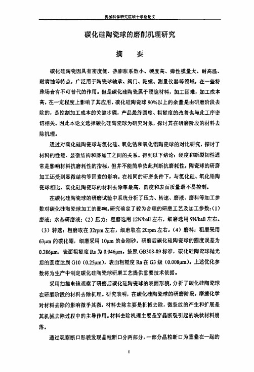
(a)碳化硅(b)氮化硅(c)氧化锆(d)氧化铝图2.1陶瓷球表2.1陶瓷材料和钢材料基本性能对比机械科学研究院硕士学位论文(a)碳化硼(c)金刚石图3.5磨料形貌图表3.2磨料硬度(b)金刚砂磨科硬度(kg/—2)金剐石碳化硼金刚砂10000左右4000~50003.4试验流程本试验的方案设计为:(1)四种陶瓷的腐蚀面分析;(2)四种陶瓷的断口分析;(3)四种陶瓷的压痕试验;(4)四种陶瓷球的研磨试验;(5)碳化硅陶瓷球的研磨试验;(6)碳化硅陶瓷球的抛光试验;(7)表面形貌分析;(8)结果分析与讨论.碳化硅陶瓷球的研磨试验碳化硅陶瓷球的抛光试验表面形貌分析结果分析与讨论图3.6试验流程图3.5性能测试及组织结构观察3.5.1密度测试按照GB/T3850-1983中的方法,测量碳化硅,氮化硅、氧化锆和氧化铝四种试样的密度。
3.5.2腐蚀试样的制备采用20、lO、5、3.5和1.5pm的金刚石研磨膏对预腐蚀面进行逐步抛光,然后在一定条件下进行腐蚀。
利用S-570型扫描电镜观察。
表3.3为试样的腐蚀方法。
表3.3试样腐蚀方法试样腐蚀条件碳化硅氮化硅氧化锆氧化铝在煮沸的铁氰化钾,氢氧化钾和水(质量比lt1:lO)的混合溶液中浸泡15min在熔融的氢氧化钾中浸泡5rain在1430'c保温lh在1480℃保温lOmin3.5.3断口试样的制备用压力机将陶瓷球压碎,将碎块用超声波清洗。
SiliconNitride
Sintering
Fracture Toughness
Addition of Y2O3 promoted the development of high aspect ratio beta Si3N4 grains Higher aspect ratio gave a higher toughness
Processing
Hot Pressing (Pressure Sintering)
Tdye=1/2 TM
• Similar to sintering -Pressure and temperature applied simultaneously • Accelerates densification by: -Increasing contact stress between particles -Rearranging particle position and improving packing
– 21.7% change in volume
Reaction Bonding
=N2 =Si =Si3N4
Reaction Bonding Concerns
High surface reaction on surface
– Closes surface pores – Prevent internal reaction – Sintering/hot pressing needed to remove excess
以光伏晶硅废料构建三维骨架增强环氧树脂的导热性能

研究与开发CHINA SYNTHETIC RESIN AND PLASTICS合 成 树 脂 及 塑 料 , 2023, 40(6): 16以光伏晶硅废料构建三维骨架增强环氧树脂的导热性能姚 健(海南大学 材料科学与工程学院,海南 海口 570228)摘 要: 以提纯的光伏晶硅废料为原料,添加高导热的片状BN粉末,采用冰模板法与真空浸渗环氧树脂(EP)相结合的方法制备了EP/Si 3N 4-SiC-BN复合材料,并研究了其性能。
结果表明:Si粉氮化反应产生的晶须在Si 3N 4-SiC-BN三维网络骨架中相互接触并分布在垂直定向的孔隙通道内;BN用量为晶硅废料质量的20%时,EP/Si 3N 4-SiC-BN复合材料的热导率最大,为1.08 W/(m ·K );随着BN含量的增加,复合材料的抗弯强度降低,BN用量为晶硅废料质量的5%时,抗弯强度最大,为133.6 MPa。
关键词: 环氧树脂 光伏晶硅废料 氮化硅 碳化硅 氮化硼 冰模板法 热导率中图分类号: TQ 323.5 文献标志码: B 文章编号: 1002-1396(2023)06-0016-06Thermal conductivity of epoxy resin enhanced by constructing3D framework with photovoltaic crystalline silicon wasteYao Jian(School of Materials Science and Engineering ,Hainan University ,Haikou 570228,China )Abstract : The epoxy resin (EP )/Si 3N 4-SiC-BN composites were prepared by the combination of ice-templating and vacuum impregnated EP,using purified photovoltaic silicon waste as raw material and adding high thermal conductivity flaky BN powder. The results showed that the crystal whiskers produced by the nitriding of silicon powder were interlinked in the Si 3N 4-SiC-BN skeletons and distributed in vertically orientedpore channels. The maximum thermal conductivity of 1.08 W/(m ·K ) was obtained for the EP/Si 3N 4-SiC-BN composites at the high 20% BN addition. The flexural strength of the composites decreased with the increase ofBN addition and the maximum flexural strength was 133.6 MPa at 5% BN addition.Keywords : epoxy resin; photovoltaic silicon waste; silicon nitride; silicon carbide; boron nitride; ice-templating; thermal conductivityDOI:10.19825/j.issn.1002-1396.2023.06.04收稿日期: 2023-05-27;修回日期: 2023-08-26。
保护渣专用词汇英中对照

保护渣专用词汇英中对照连铸(continuous casting)钢种(steel grade)浇铸断面(casting format)拉速(casting speed)润滑(lubrication)传热(heat transfer)菜籽油(rape seed oil)热流(heat flow)浸入式水口(SEN-submerged entry nozzle)坯壳(steel sheel)保护渣渣膜(slag film)粉煤灰(fly ash)石灰石(limestone)苏打灰(soda ash)萤石(fluorite)硅酸盐(silicate)矿物质(mineral)合成渣(synthetic powder)熔点(melt point)成分(composition)性能(performance)炭黑(carbon black)微合金钢(microalloy steel)不锈钢(stainless steel)渣耗(powder consumption)粘结漏钢(sticker breakout)表面质量(surface quality)摩擦力(friction force)黏度(viscosity)熔化速度(melting rate)凝固系数(solidification coefficient)薄板坯(thin slab )异型坯(beam blank近终形连铸(near net shape continuous casting)石墨(black lead)焦炭(coke)硅灰石(CaO·SiO2)碱度(basicity)粉渣(granulated powder)实心颗粒渣(sincere granuled powder)预熔型保护渣(prefused powder)低碳铝镇静钢(LCAK-low carbon Alumina killed steel)针孔(pinhole)高碳钢(high carbon steel)弯月面(meniscus)振痕(oscillation mark)熔化温度(melting temperature)相图(phase diagram)伪硅灰石(wollastonite,又名tabular spar) 磷(phosphorus)硫(sulfur)助熔剂(fluxing agent)结晶(crystallizing)枪晶石(Cuspidine)钙黄长石(Akermanite)离子(ion)CaO(calcium oxide)氧化物夹杂物(oxide inclusion)玻璃性(vitrecence)CaF2(fluorite)枪晶石(3CaO。
光伏行业英文词汇

太阳电池 solar cell通常是指将太阳光能直接转换成电能的一种器件。
硅太阳电池silicon solar cell硅太阳电池是以硅为基体材料的太阳电池。
单晶硅太阳电池single crystalline silicon solar cell单晶硅太阳电池是以单晶硅为基体材料的太阳电池。
非晶硅太阳电池〔a—si太阳电池〕amorphous silicon solar cell用非晶硅材料及其合金制造的太阳电池称为非晶硅太阳电池,亦称无定形硅太阳电池,简称a—si太阳电池。
多晶硅太阳电池polycrystalline silicon solar cell多晶硅太阳电池是以多晶硅为基体材料的太阳电池。
聚光太阳电池组件photovoltaic concentrator module系指组成聚光太阳电池,方阵的中间组合体,由聚光器、太阳电池、散热器、互连引线和壳体等组成。
电池温度cell temperature系指太阳电池中P-n结的温度。
太阳电池组件外表温度solar cell module surface temperature系指太阳电池组件背外表的温度。
大气质量〔AM〕Air Mass (AM)直射阳光光束透过大气层所通过的路程,以直射太阳光束从天顶到达海平面所通过的路程的倍数来表示。
太阳高度角solar太阳高度角solar elevation angle太阳光线与观测点处水平面的夹角,称为该观测点的太阳高度角。
辐照度irradiance系指照射到单位外表积上的辐射功率〔W/m2〕。
总辐照〔总的太阳辐照〕total irradiation (total insolation)在一段规定的时间内,〔根据具体情况而定为每小时,每天、每周、每月、每年〕照射到某个倾斜外表的单位面积上的太阳辐照。
直射辐照度direct irradiance照射到单位面积上的,来自太阳圆盘及其周围对照射点所张的圆锥半顶角为8o的天空辐射功率。
silicone
siliconeSiliconeIntroduction:Silicone, also known as polydimethylsiloxane, is a versatile and widely used synthetic material. It is composed of silicon, oxygen, and hydrocarbon groups, making it a unique compound with various applications. Silicones are commonly found in many industries due to their excellent thermal stability, chemical resistance, and low toxicity. In this document, we will explore the properties, uses, and manufacturing process of silicone.Properties:1. Thermal Stability:Silicone exhibits remarkable thermal stability, allowing it to withstand extreme temperature conditions. It can remain stable across a wide range of temperatures, from as low as -100°C to as high as 300°C. This property makes silicone an ideal material for applications in industries such as automotive, aerospace, and electrical.2. Chemical Resistance:Silicone is highly resistant to various chemicals, including acids, bases, solvents, and oils. This exceptional resistance makes it a preferred choice for manufacturing gaskets, seals, and O-rings. Silicone can maintain its chemical integrity even when exposed to harsh environments, ensuring long-lasting performance.3. Low Toxicity:Silicone possesses low toxicity and is considered safe for many applications, including food and medical industries. It is biocompatible, non-allergenic, and non-carcinogenic. These properties make silicone suitable for use in medical implants, baby products, and food-grade containers.Uses:1. Sealants and Adhesives:Silicone-based sealants and adhesives are extensively used in construction, automotive, and household applications. Silicone sealants provide excellent water resistance, flexibility, and durability, making them ideal for sealing gaps and joints.Silicone adhesives offer high bonding strength and can adhere to various surfaces, including glass, metal, and plastic.2. Lubricants and Greases:Silicone lubricants are valued for their exceptional temperature stability and compatibility with various materials. They offer low friction and provide long-lasting lubrication. Silicone greases are commonly used in automotive, electrical, and mechanical applications to reduce wear and protect against corrosion.3. Medical and Personal Care Products:Silicone's biocompatible and non-reactive nature makes it a preferred material for medical and personal care products. It is used in a wide range of applications, including medical implants, prosthetics, contact lenses, and skincare products. Silicone is hypoallergenic, easy to clean, and comfortable to wear, ensuring its popularity in healthcare and personal care industries.Manufacturing Process:The manufacturing process of silicone involves several steps:1. Raw Material Preparation:Silicone is produced by hydrolyzing and polymerizing silanes (compounds containing silicon and hydrogen). The silane compounds are mixed with catalysts and other additives to form a silicone base.2. Polymerization:The silicone base is heated and subjected to a controlled polymerization process. This process allows the polymer chains to grow, resulting in the formation of the desired silicone polymer.3. Vulcanization:To enhance the properties of silicone, such as tear resistance and elasticity, vulcanization is performed. The silicone polymer is mixed with crosslinking agents and heated to promote crosslinking between polymer chains. This step greatly improves the mechanical properties of silicone.4. Fabrication:After vulcanization, the silicone material can be shaped using various fabrication techniques such as molding, extrusion, or calendaring. These techniques enable the production ofdifferent silicone products, including sheets, tubes, gaskets, and custom parts.Conclusion:Silicone is a highly versatile material that has revolutionized various industries. Its exceptional properties, including thermal stability, chemical resistance, and low toxicity, have made it indispensable in sectors such as construction, automotive, healthcare, and personal care. The manufacturing process of silicone involves several steps, including raw material preparation, polymerization, vulcanization, and fabrication. As technology advances, the potential applications of silicone continue to expand, and its importance in our daily lives cannot be overstated.。
氮化硅陶瓷

氮化硅陶瓷的研究作者:王雪董茁卉张磊杨柳范雪孙亚静、陈雅倩、吕海涛、徐志华、张国庆、于希晶。
(吉林化工学院132022)摘要:氮化硅陶瓷是一种有广阔发展前景的耐高温高强度结构陶瓷。
氮化硅陶瓷在高技术陶瓷中占有重要地位,其具有高性能(如强度高、硬度高、抗热震稳定性好、疲劳韧性高、室温抗弯强度高、耐磨、耐化学腐蚀和很好的高温稳定性、抗氧化性能等),与其他陶瓷相比,氮化硅陶瓷比重小,热膨胀系数低,抗热冲击性好,断裂韧性高,是一种理想的高温结构材料和高速切削工具陶瓷材料。
因此氮化硅陶瓷在航天航空、汽车发动、机械、化工、石油等领域有着广泛的用途,也为新型高温结构材料的发展开创了新局面。
目前氮化硅陶瓷制品主要存在的问题是产品韧性低、成本高。
今后应改善制粉、成型、和烧结工艺及氮化硅与碳化硅的复合化,研制出性能更佳的氮化硅陶瓷。
本文介绍了氮化硅陶瓷的基本性能,综述了氮化硅陶瓷的制备工艺和应用领域,并展望了氮化硅陶瓷的发展前景。
关键词:氮化硅;陶瓷;性能;应用;Abstract:Silicon nitride ceramics is high temperature and high strength structuralceramics has a broad development prospect. Silicon nitride ceramics occupies an important position in the high technology ceramics, it has high performance(such as high strength, high hardness, good thermal shock stability, hightemperature fatigue toughness, high bendingstrength, wear resistance,chemical corrosion resistance and high temperature stability, good oxidation resistance properties), compared withother ceramics, silicon nitride ceramics the proportion of small, low thermal expansion coefficient, good heat shock resistance, high fracture toughness, is a kind of ideal candidates for high temperature structural materials and high speed cutting tool ceramics.Therefore, silicon nitride ceramicsin aerospace, automobile engine, mechanical,chemical, oil and other fields have a wide range of uses, has created a new situation for the development of new high temperature structural materials. Thesilicon nitride ceramic products the main problems is the product of low toughness, high cost. We should improve milling, molding compound, and the sintering process and silicon nitride and silicon carbide, silicon nitrideceramicsdeveloped better performance. This paper introduces thebasic properties of silicon nitride ceramics, reviews the preparation technology and application of silicon nitride ceramics, and prospects the future development of silicon nitride ceramics.Keywords:silicon nitride ceramic;performance;application;引言自20世纪60年代开始,氮化硅陶瓷作为最优异的非氧化物陶瓷材料之一,被期望能用于燃气轮机上,而逐渐蓬勃地发展了40多年,成为了一个以氮化硅为基的氮陶瓷领域。
交变振动载荷下Al_2O_3陶瓷钢摩擦副的摩擦磨损性能_唐媛媛

基金项目:国家自然科学基金资助项目 (50675185));教育部新世纪人才培养计划资助(NCET06-0708) 收稿日期:2009-06-05;修订日期:2009-06-29 通讯作者:谭援强,教授,博士;电话:0731-58293210;E-mail: tanyq@
418
Technology & Equipment, Xiangtan University, Xiangtan 411105, China)
Abstract: The load applied on Al2O3 ceramic/45 steel coupling is not the constant one but the complex vibration load, so it is important to study on the wear properties of Al2O3 ceramic under vibration load. The friction and wear properties of the Al2O3 ceramic/45 steel coupling under alternative vibration load was studied by using a new wear tester with ring-on-block friction pairs, and its results were compared with those under normal load condition. The worn surface of the Al2O3 ceramics was observed by scanning electron microscopy and carried out spectroscopy analysis. The results show that wear volume under the alternative vibration load is higher than that of the normal load in dry condition; and there are micro cracks on the worn surface under the above vibration load, and the wear mechanisms of Al2O3 ceramic are brittle fracture, abradent particles wear and ploughing wear as well. Compared with the initial surface, the worn surface was covered by a layer of metal transfer film, of which the mainly contents are ferric oxides. Key words: vibration load; Al2O3 ceramic; friction and wear; transfer film; static load
直写成型用碳化硅浆料及其流变性能研究
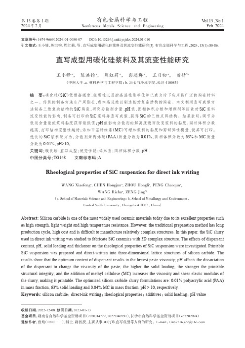
第15卷第1期2024年2月有色金属科学与工程Nonferrous Metals Science and EngineeringVol.15,No.1Feb. 2024直写成型用碳化硅浆料及其流变性能研究王小锋a , 陈洪钧a , 周红莉a , 彭超群a , 王日初a , 曾婧*b(中南大学,a.材料科学与工程学院; b.冶金与环境学院,长沙 410083)摘要:碳化硅(SiC )凭借高强度、轻质性以及耐高温性能等优势已成为时下应用最广泛的陶瓷材料之一。
传统的制备方法生产周期长、成本高且难以制造相对复杂结构的陶瓷。
本文利用直写成型方法制备三维复杂结构的SiC 陶瓷,研究分散剂含量、pH 值、固相体积分数和增稠剂等因素对SiC 浆料流变性能的影响,制备可打印的SiC 浆料并直写成型,获得SiC 的三维点阵结构。
结果表明:调节分散剂含量能使浆料黏度获得最低值;pH 值影响分散剂的解离度进而改变浆料的黏度;固相体积分数越高,打印结构完整性越好;添加甲基纤维素(MC )可增加浆料的黏度和剪切弹性模量,使其可打印。
优化的SiC 浆料配方为:分散剂聚丙烯酸(PAA )质量分数为0.01%,固相体积分数为63%和MC 质量分数为0.04%,pH>10。
关键词:碳化硅;直写成型;流变性能;添加剂;固相体积分数;pH 中图分类号:TG148 文献标志码:ARheological properties of SiC suspension for direct ink writingWANG Xiaofeng a , CHEN Hongjun a , ZHOU Hongli a , PENG Chaoqun a ,WANG Richu a , ZENG Jing *b(a. School of Materials Science and Engineering ; b. School of Metallurgy and Environment ,Central South University , Changsha 410083, China )Abstract: Silicon carbide is one of the most widely used ceramic materials today due to its excellent properties such as high strength, light weight and high temperature resistance. However, the traditional preparation method has long production cycle, high cost and is difficult to manufacture relatively complex structures. In this paper, the SiC slurry used in direct ink writing was studied to fabricate SiC ceramics with 3D complex structure. The effects of dispersant content, pH, solid loading and thickener on the rheological properties of SiC suspension were investigated. Printable SiC suspension was prepared and direct-written into three-dimensional lattice structures of silicon carbide. The results show that the optimum content of dispersant results in the lowest paste viscosity; pH affects the dissociation of the dispersant to change the viscosity of the paste; the higher the solid loading, the stronger the printable structural integrity; and the addition of methyl cellulose (MC) increases the viscosity and shear elastic modulus of the slurry, making it printable. The optimized silicon carbide slurry formulations are: 0.01% polyacrylic acid (PAA)in mass fraction, 63% solid loading and 0.04% MC in mass fraction, pH > 10, respectively.Keywords: silicon carbide ; direct-ink writing ; rheological properties ; additives ; solid loading ; pH value收稿日期:2022-12-08;修回日期:2023-01-13基金项目:湖南省自然科学基金资助项目(2020JJ4729,2022JJ40591);长沙市自然科学基金资助项目(kq2202094)通信作者:曾婧(1990— ),博士,副教授,主要从事3D 打印直写成型等方面的研究。
羟基磷灰石及其复合生物陶瓷材料研究进展
羟基磷灰石及其复合生物陶瓷材料研究进展生物医学工程学杂志 1999年第0期第16卷无机生物材料及有机/无机复合材料组作者:张玉军尹衍升王迎军单位:张玉军尹衍升(山东工业大学材料学院,济南250061);王迎军(华南理工大学材料系,广州510632)关键词:羟基磷灰石;复合材料;生物陶瓷摘要综述了羟基磷灰石陶瓷及其复合生物陶瓷材料方面的最新进展,并简单探讨了HAP生物陶瓷的发展方向。
Advancement of Hydroxyapatite-Based Bioceramic Composites 羟基磷灰石{Ca10(PO4)6(OH)2,hydroxyapatite,简称HAP}具有极好的生物相容性和生物活性,被认为是最有前途的陶瓷人工齿和人工骨置换材料。
然而,纯HAP陶瓷的机械性能比较差,例如,断裂韧性(K IC)不超过1.0 MPa·m1/2,而且,在潮湿的环境中Weibull因子较低(n=5~12),作为人工种植体其使用可靠性较差。
到目前为止,HAP陶瓷不能用作承载种植体,它在医学上的应用仅限于小的非承载种植体、粉末、涂层和低承载的多孔种植体。
为了提高HAP陶瓷材料的使用可靠性,近十几年来已经进行了许多研究工作。
本文将结合我们的实验工作,简单探讨在该领域的某些研究进展。
1 HAP粉末的制备制备HAP粉末有许多方法,主要有湿法和固态反应法[1]。
固态反应法往往给出符合化学计量、结晶完整的产品,但是它们要求相对较高的温度和热处理时间,而且。
这种粉末的可烧结性较差。
湿法包括:沉淀法[2,3]、水热合成法[4]和溶胶-凝胶法[5~8]等。
用水热合法成法获得的HAP材料一般结晶程度高,Ca/P接近化学计量值。
溶胶-凝胶法可以得到无定形、纳米尺寸、Ca/P比接近1.67的HAP粉末。
用沉淀法在温度不超过100 ℃的条件下,可制备纳米尺寸的纤维颗粒粉末[9]。
就HAP粉末的制备而言,制备工艺已经比较成熟。
近α型TG6高温钛合金中硅化物的沉淀析出行为
近α型TG6高温钛合金中硅化物的沉淀析出行为李娟;蔡建明;段锐【摘要】The precipitation behavior of silicide in near-alpha TG6 titanium alloy under the different heat treatment states was studied using OM, TEM. The results show that the silicide precipitates asymmetrically along the primary β layer or in α matrix. Silicide is HCP S2 type, generally long-rod or ellipsoidal precipitated inhomogeneously. There is no certain orientation relationship between the silicide and α matrix. After a long period thermal exposure at 600℃ , The size and amount of silicide increase with the extension of the heat exposure time. The interactions of silicide and dislocation cause the dislocation accumulation, which can effectively hinder dislocation glide to improve the alloy's strength.%采用光学显微镜(OM),透射电镜(TEM)研究了近α型TG6钛合金在不同热处理状态下硅化物的沉淀析出行为.结果表明,硅化物优先在原始β片层上析出,同时,在有些α基体中也有硅化物的析出.硅化物呈现长杆状或椭球状,为六方结构的S2型( (TiZr)6Si3)硅化物,与α基体没有确定的取向关系.在透射电镜下可以看出,硅化物分布并不均匀.在600℃热暴露过程中,随着热暴露时间的延长,硅化物的数量增多尺寸增大.析出的硅化物与位错发生交互作用形成位错堆积,可以有效阻碍位错的滑移运动,提高合金强度.【期刊名称】《航空材料学报》【年(卷),期】2012(032)005【总页数】5页(P32-36)【关键词】TG6钛合金;硅化物;沉淀析出【作者】李娟;蔡建明;段锐【作者单位】北京航空材料研究院,北京100095;北京航空材料研究院,北京100095;北京航空材料研究院,北京100095【正文语种】中文【中图分类】TG146.2随着航空发动机推重比提高,压气机的工作条件更为复杂和苛刻。
- 1、下载文档前请自行甄别文档内容的完整性,平台不提供额外的编辑、内容补充、找答案等附加服务。
- 2、"仅部分预览"的文档,不可在线预览部分如存在完整性等问题,可反馈申请退款(可完整预览的文档不适用该条件!)。
- 3、如文档侵犯您的权益,请联系客服反馈,我们会尽快为您处理(人工客服工作时间:9:00-18:30)。
Fracture behavior of silicon nitride ceramics subjected to hypervelocity impactN.Kawai *,K.Tsurui,D.Shindo,Y.Motoyashiki,E.SatoInstitute of Space and Astronautical Science,Japan Aerospace Exploration Agency,3-1-1Yoshinodai,Chuo,Sagamihara,Kanagawa 252-5210,Japana r t i c l e i n f oArticle history:Received 10August 2010Received in revised form 13January 2011Accepted 14January 2011Available online 22January 2011Keywords:Hypervelocity impact Impact-induced damage Two-stage light-gas gun Silicon nitride ceramicsa b s t r a c tA new advanced ceramic thruster made of monolithic silicon nitride ceramics was developed for the planetary exploration spacecraft AKATSUKI (PLANET-C)at Institute of Space and Astronautical Science (ISAS),Japan Aerospace Exploration Agency (JAXA).To ensure its operation onboard the spacecraft,the reliability of the ceramic thruster against micrometeoroid hypervelocity impact has been investigated.Silicon nitride plates were impacted by spheres of stainless-steel and other materials with 0.2e 0.8-mm diameters in the velocity range up to 8.0km/s using a two-stage light-gas ing crater depth data under various impact conditions,the penetration equation of silicon nitride was determined.The impacted samples showed fracture patterns of three types:cratering,cratering with spallation,and perforation.These fracture patterns were well categorized by the multiple forms of the penetration equation.Ó2011Elsevier Ltd.All rights reserved.1.IntroductionA thruster is a small rocket engine used to control the attitude and orbit of a spacecraft.To achieve higher thrust performance,increased combustion temperature and a decreased mass of thruster components must be attained.Institute of Space and Astronautical Science (ISAS),Japan Aerospace Exploration Agency (JAXA)devel-oped a new advanced ceramic thruster made of monolithic silicon nitride for the planetary exploration spacecraft AKATSUKI (PLANET-C),sent on a Venus climate orbiter mission [1].Silicon nitride ceramic is an ideal structural material for high-temperature appli-cations such as heat engine and heat recovery system components because of its outstanding high-temperature strength,corrosion and erosion resistance,and chemical stability,coupled with low density.The design and veri fication of the ceramic thruster were conducted with consideration of its quasi-static strength under launching and firing conditions [1].In addition,its reliability against micromete-oroid impact has also been veri fied to ensure the operation of the planetary exploration spacecraft [2].For this study,following the veri fication under the thruster condition [2],the failure behavior of silicon nitride subjected to hypervelocity impact was investigated.Hypervelocity impact experiments were performed on a silicon nitride plate in the velocity range up to 8.0km/s.The impact failure morphology of the silicon nitride was examined.The penetration equation of silicon nitride was derived from the hypervelocity impact test data and analysis.2.Hypervelocity impact experimentThe material used in this study is a commercially available gas-turbine-grade silicon nitride,SN282,manufactured by Kyocera Corp.,which is densi fied via gas-pressure sintering with Lu 2O 3as a sintering additive and toughened with microstructures tailored to achieve elongated grain structures.The bulk density is 3.38Mg/m 3.The elastic modulus,bulk modulus,shear modulus,and Poisson ’s ratio are 316GPa,244GPa,123GPa,and 0.28,respectively [3].Impacted targets were 30mm Â50mm or 50mm square plates with five different thicknesses:1.0,1.5,2.0,2.5and 3.0mm.Hypervelocity experiments were performed using a two-stage light-gas gun at ISAS/JAXA [4],with the exception of the two highest velocity experiments performed at the White Sands Test Facility of the NASA Johnson Space Center [5].The projectiles used were spheres of stainless-steel ðr ¼7:89Mg =m 3Þ,Al ðr ¼2:78Mg =m 3Þ,Al 2O 3ðr ¼3:90Mg =m 3Þ,glass ðr ¼2:20Mg =m 3Þ,WC ðr ¼14:50Mg =m 3Þ,Pt ðr ¼21:10Mg =m 3Þand Ir ðr ¼22:70Mg =m 3Þof 0.2e 0.8-mm diameters.These projectiles were launched using a buckshot technique [6]or a single microparticle launching technique [4,5].The sample-plate was mounted on an acrylic frame with an adhesive tape so that there was a free rear surface and the sample was fixed in a practically uncon fined manner.The resulting crater depths for unperforated samples were measured using a laser microscope.Some samples were cut along the impact axis using a diamond saw to examine the internal damage.The cut samples were embedded in an epoxy resin and the sectioned surfaces were polished before optical microscope observations.*Corresponding author.Tel.:þ815033627539;fax:þ81427598461.E-mail address:nkawai@isas.jaxa.jp (N.Kawai).Contents lists available at ScienceDirectInternational Journal of Impact Engineeringjo urn al homepag e:/locate/ijimpeng0734-743X/$e see front matter Ó2011Elsevier Ltd.All rights reserved.doi:10.1016/j.ijimpeng.2011.01.003International Journal of Impact Engineering 38(2011)542e 5453.Results3.1.Impact failure morphologyIn these experiments,fracture patterns of three types were observed:cratering,cratering with rear surface spallation,and perforation.The cross-sections along the impact axis of the impacted samples revealing three fracture patterns are,respec-tively,shown in Fig.1.In the case of the cratering-only fracture (Fig.1(a)),highly deformed and damaged silicon nitride,the white region in the images,was observed immediately beneath the crater.Numerous conical cracks propagated inside the sample from this damaged region.The horizontal planer cracks were also observed below the middle plane of the impacted sample.In the case of rear surface spallation with cratering,spall frac-tures of two kinds were observed.The first one is thin planar spall fracture (Fig.1(b)),which was usually observed in metal [7,8].This thin planar fracture near the rear surface is induced by a rarefaction wave formed by the re flection of a shock wave from the rear free surface.The formation of this spall fracture is associated with the shock wave propagation.Therefore the thin planar spall is formed during the early stages of impact crater formation.The thin planar spallation was observed only in the thick samples impacted at greater than 5.5km/s,indicating that a suf ficiently strong shock wave to trigger the planar spallation reaches the rear free surface in these impact conditions.Another rear surface spallation is a conical spall fracture (Fig.1(c)),in which many conical cracks that had propagated from crater were observed;some cracks reached the rear surface.The horizontal cracks were much more numerous than in the cratering-only case.Although thin planar spall fracture would also occur in this fracture pattern,the dominant fracture resulted from connec-tion of the extended conical cracks and horizontal cracks.Thecrack-propagation velocity is slower than the shock wave velocity propagated into the silicon nitride.Therefore,the conical spall fracture is formed later than the thin planar spall fracture.This fracture sequence was shown by the numerical simulation of the hypervelocity impact of silicon nitride using a hydrocode [9].In the case of perforation fracture (Fig.1(d)),the through-hole was formed by linking the front-surface crater and the rear surface conical spall.Some cracks that had propagated from the through-hole were also observed.3.2.Crater depthAll the experimental data are summarized in Table 1and Table 2.In Fig.2,the crater depth P c (mm)normalized by the projectile diameter d p (mm)is plotted versus the projectile velocity v p (km/s).In the case of the stainless-steel projectile,the normalized crater depth shows good correlation against the projectile velocity,independently of projectile diameters.Simple power-law fitting to all data of stainless-steel projectile yieldsP ss d p¼0:69v 0:64p ;(1)where P ss is crater depth (mm)by the impact of a stainless-steel projectile.The correlation coef ficient of this equation is 0.89.This simple power-law forces the crater depth to zero at v p ¼0although the critical velocity for penetration is expected to be greater than zero.However,previous studies [10,11]show that the critical velocity for crater formation of silicon nitride impacted by ceramics spheres with 1mm diameter is about 80m/s.The impact velocities of this study (from 1.5to 8.3km/s)are considerably higher than the critical velocity.Therefore,the effect of the critical velocity on the crater formation is considered to be negligible in this study.The differences of the crater depths between the stain-less-steel projectile and other materials are caused by differences of the projectiledensity.Fig.1.Cross-sections of the silicon nitride plate subjected to hypervelocity impact for failure patterns of different types.(a)Only cratering.Target thickness is 3.0mm and a 0.3-mm stainless-steel sphere was impacted at 4.43km/s.(b)Thin planar spallation.Target thickness is 2.0mm and a 0.3mm-aluminum sphere was impacted at 6.61km/s.(c)Conical spallation.Target thickness is 1.5mm and a 0.5-mm stainless-steel sphere was impacted at 1.94km/s.(d)Perforation.Target thickness is 1.5mm and a 0.5-mm stainless-steel sphere was impacted at 3.26km/s.Table 1Experimental data of hypervelocity impact tests on silicon nitride ceramics using stainless-steel projectiles.ProjectileSilicon nitride targetShot No.Material d p /mm v p /km/s t t /mm Fracture type P c /mm 652Stainless-steel0.304.05 2.0Crater0.455968 4.16 1.0Perforation e 969 4.30 1.5Conical Spall 0.5171004 4.41 1.0Perforation e 838 4.43 3.0Conical Spall 0.564376 5.63 1.5Conical Spall 0.60642206a 0.40 6.83 2.0Perforation e 42207a 8.31 2.0Perforation e 10090.501.94 1.5Conical Spall 0.6081315 1.96 1.5Conical Spall 0.42113202.19 2.0Crater0.4811006 2.80 1.0Perforation e 1335 2.85 2.5Conical Spall 0.6961205 2.86 3.0Crater0.8051333 3.02 2.0Conical Spall 0.6911323 3.06 2.0Conical Spall 0.6101326 3.26 2.0Conical Spall 0.7301325 3.31 3.0Crater0.8151556 3.38 1.5Perforation e 1553 3.52 2.0Conical Spall 0.8351317 3.79 1.5Perforation e 1559 3.79 2.0Conical Spall 0.7971563 3.85 2.0Perforation e 1329 4.12 2.5Conical Spall 0.8371562 4.25 2.0Perforation e 10130.801.351.0PerforationeaPerformed at the White Sands Test Facility of the NASA Johnson Space Center.N.Kawai et al./International Journal of Impact Engineering 38(2011)542e 5455434.DiscussionThe penetration equations for hypervelocity impacts are usually formulated as a power-law equation of the projectile diameter,the projectile density and the projectile velocity [12e 16].The crater depth data normalized by the projectile diameter for the stainless-steel projectiles are well fitted by the power-law equation of projectile velocity,as shown in Fig.2.Therefore,the exponent for d p is assumed to be 1.0in this study.The effect of the projectile density on the crater formation is estimated from the differences of the crater depths between stainless-steel projectile and other material paring the crater depth data of Al,Ir and Al 2O 3projectiles to the estimated crater depths of stainless-steel projectile with the same velocity and diameter,the exponent for the projectile density is calculated for each data point asP c ss¼r p r ssa;(2)where r p denotes the projectile density (Mg/m 3),r ss represents thedensity of stainless-steel (Mg/m 3)and a stands for the exponent for the projectile density.The values of P ss were estimated using Eq.(1).After calculation of a for each data point of Al,Ir and Al 2O 3projec-tiles,the a was determined to be 0:73Æ0:19as an average value.In Fig.3,the crater depth normalized by d p and r 0:73pare plotted against the projectile velocity.The graph shows good correlation between the normalized crater depth and projectile velocity for all projectile materials.By fitting the data to the power-law form for the projectile velocity,the penetration equation for silicon nitride is determined asP c ¼0:142d p r 0:73pv 0:67p :(3)The correlation coef ficient for this equation is 0.95.The standard deviation of the exponent of v p is Æ0:07.Some penetration equa-tions for metal,glass,and thermal protection materials have been proposed [13e 16].The exponents of projectile velocity in these equations are about 2/3and show only slight differences each other.In the case of the exponents of projectile density,previous studies show a range of values from about 0.3to 0.7because of the limited variation of projectile density in the data set used by different researchers [13,14].The exponents of projectile velocity and density for silicon nitride are also consistent with these previous results.The penetration equation has been used to assess the fracture resistance of a thin target [12,15,16].The plate thickness necessary to prevent fracture,t f (mm),is usually expressed in terms of a multiple of the penetration equation:t f ¼kP c ,where k is the factor depending on the fracture pattern.In Fig.4,the fracture patterns observed in this study are shown in the t t /d p /r p versus v p plane,where t t is the target thickness (mm).The values of the factor k were determined to express the boundaries of fracture patterns on the morphology map shown in Fig.4.As a result,the equations for the critical thickness of silicon nitride to prevent the conical spallation and the perforation are determined as follows:t f ¼0:142kd p r 0:73pv 0:67p ;(4)k ¼2:4Æ0:2to prevent the perforation ;k ¼3:7Æ0:2to prevent the conical spallation :The calculated t f using each k is depicted in Fig.4:a dashed line and a dashed-dotted line represent the target thickness to prevent the conical spallation and the perforation,respectively.BothcalculatedFig.2.Relation between penetration depth to projectile diameter ratio and projectilevelocity.The dashed line shows power-low fitting to the data of the stainless-steel projectile (Eq.(1)).Fig.3.Penetration depth to projectile diameter ratio as a function of projectile velocity with projectile density scaling.The dashed line shows the penetration equation of silicon nitride determined in this study (Eq.(3)).Table 2Experimental data of hypervelocity impact tests on silicon nitride ceramics using Al,Al 2O 3,Glass,WC,Pt and Ir projectiles.ProjectileSilicon nitride target Shot No.Material d p /mm v p /km/s t t /mm Fracture type P c /mm 577Al0.205.06 2.0Crater 0.147478 5.10 3.0Crater 0.1556566.42 2.0Crater0.1906490.30 6.61 2.0Planer Spall 0.350657Al 2O 30.20 5.41 2.0Crater0.2446510.30 5.78 2.0Planer Spall 0.429835Glass 0.30 4.03 2.0Crater 0.199966 4.23 1.5Crater0.154661WC 0.50 5.51 2.5Perforation e 1331Pt 0.33 3.94 1.0Perforation e 1217Ir0.391.501.5Conical Spall0.514N.Kawai et al./International Journal of Impact Engineering 38(2011)542e 545544curves represent the boundaries of fracture patterns very well.The values of k for metallic target have been estimated as 2.0for perfo-ration and 2.2for rear surface spallation [12,16].The k for spallation of silicon nitride is much bigger than that of metal.This is because the spall strength of ceramics is lower than that of metal.In contrast,the k for perforation of silicon nitride is little bigger than that of metal.The perforation occurs by connecting the crater and rear-side spallation.As mention above,ceramics are vulnerable to spallation.In contrast,the high hardness and compressive strength of ceramics are effective in preventing the penetration.It is expected that the difference of k for perforation between silicon nitride and metal become relatively small as a result of the combination of their penetration and spallation resistances.In the case of the thin planar spallation,the equation for the boundary of fracture pattern can not be determined in this study because of the scarcity of data points for this fracture pattern.To reveal the thin planar spallation,the target thickness must be suf fi-ciently thick to avoid the conical spallation.Furthermore,the projectile velocity must be high enough to generate a shock wave that is suf ficiently strong to trigger the planar spallation at the rear surface.The data points for the thin planar spallation observed in this study follow this trend.The expected boundary between the cratering and the thin planar spallation is shown as a dotted line in Fig.4.From these results,we can predict the fracture pattern of the silicon nitride subjected to hypervelocity impact using the pene-tration equation and k values.ConclusionIn this study,to determine the hypervelocity impact-induced fracture behavior of silicon nitride,hypervelocity impact tests wereperformed on a silicon nitride plate by impacting spheres of stainless-steel and other materials with 0.2e 0.8-mm diameters in the velocity range up to 8.0km/s.The penetration equation was determined using crater depth data under various impact condi-tions:P c ¼0:142d p r 0:73p v 0:67p.Impact-induced fracture patterns of three types were observed:cratering,cratering with spallation,and perforation.The boundaries of these fracture patterns were well described by the multiple form of the penetration equation deter-mined in this study:t f ¼kP c ,k ¼2:4for the perforation,and k ¼3:7for the conical spallation.Consequently,the fracture pattern of the silicon nitride subjected to hypervelocity impact can be pre-dicted using the obtained penetration equation.AcknowledgmentsThe authors are grateful to S.Hasegawa for his technical assis-tance with hypervelocity impact experiments.This research was supported by the Space Plasma Laboratory,ISAS,JAXA.References[1]Sawai S,Sato E,Uesugi KT,Furukawa K,Mishima H,Morishima K,et al.Development of ceramic based 500N class bipropellant thruster.In:Proc.the 56th International Astronautical Congress,IAC-05e C4.3.01;2005.[2]Motoyashiki Y,Hasegawa S,Okudaira K,Sato E.Micrometeoroid impact onceramic thin components for interplanetary probe.Int J Impact Eng 2008;35:1666e 71.[3]Dandekar DP,Casem DT,Motoyashiki Y,Sato E.Shock response of siliconnitride.In:Elert ML,Buttler WT,Furnish MD,Anderson WW,Proud WG,editors.Shock compression of condensed matter e 2009.New York:AIP;2009.p.985e 8.[4]Kawai N,Tsurui K,Hasegawa S,Sato E.Single microparticle launching methodusing two-stage light-gas gun for simulating hypervelocity impacts of micrometeoroids and spacedebris.Rev Sci Instrum 2010;81:115105.[5]Crews JL,Christiansen EL.The NASA JSC hypervelocity impact test facility(HIT-F),AIAA Paper 92e 1640;1992.[6]Taylor EA,Tsembelis K,Hayhurst CJ,Kay L,Burchell MJ.Hydrocode modellingof hypervelocity impact on brittle materials:depth of penetration and conchoidal diameter.Int J Impact Eng 1999;23:895e 904.[7]Shockey DA,Curran DR,DeCarli PS.Damage in steel plates from hypervelocityimpact.I.Physical changes and effects of projectile material.J Appl Phys 1975;46:3766e 75.[8]Moritoh T,Matsuoka S,Ogura T,Nakamura KG,Kondo K,Katayama M,et al.Dynamic failure of steel under hypervelocity impact of polycarbonate up to 9km/s.J Appl Phys 2003;93:5983e 8.[9]Kawai N,Kakimoto Y,Motoyashiki Y,Sato E.Damage evaluation of siliconnitride components subjected to hypervelocity impact.In:Schäfer F,Hier-maier S,editors.Proc.11th hypervelocity impact symposium,in press.[10]Akimune Y,Katano Y,Matoba K.Spherical-impact damage and strengthdegradation in silicon nitrides for automobile turbocharger rotors.J Am Ceram Soc 1989;72:1422e 8.[11]Shin HS,Maekawa I.Characterization of particle impact damage and residualstrength degradation behaviors in structural ceramics.JSME Int J A 1995;38:116e 22.[12]Cour-Palais BG.Hypervelocity impact in metals,glass and composites.Int JImpact Eng 1987;5:221e 37.[13]Herrmann W,Wilbeck JS.Review of hypervelocity penetration theories.Int JImpact Eng 1987;5:307e 22.[14]Yu SB,Sun GC,Tan QM.Experimental laws of cratering for hypervelocityimpacts of spherical projectiles into thick target.Int J Impact Eng 1994;15:67e 77.[15]Christiansen EL,Friesen L.Penetration equations for thermal protectionmaterials.Int J Impact Eng 1997;20:153e 64.[16]Cour-Palais BG.A career in applied physics:apollo through space station.Int JImpact Eng 1999;23:137e68.Fig.4.Failure morphology map against the target thickness to projectile diameter ratio with projectile density scaling and the projectile velocity.The dashed line represents the target thickness to prevent conical spallation (Eq.(4)).The dashed-dotted line represents the target thickness to prevent perforation (Eq.(4)).The dotted line shows the expected boundary between the cratering and thin planar spallation.N.Kawai et al./International Journal of Impact Engineering 38(2011)542e 545545。