EMC50DREH中文资料(List Unclassifed)中文数据手册「EasyDatasheet - 矽搜」
电表emc标准
电表emc标准全文共四篇示例,供读者参考第一篇示例:电表是用于测量电能消费的重要设备,其准确性和稳定性对于电力行业的运行至关重要。
为了确保电表的准确性和可靠性,国际上制定了一系列的电磁兼容(EMC)标准,以规定电表在不同电磁环境下的性能要求和测试方法。
在本文中,我们将探讨电表EMC标准的相关内容。
电表EMC标准主要包括以下几个方面:抗干扰能力、抗辐射干扰、抗瞬时干扰和静电放电等。
这些标准旨在确保电表在各种电磁环境下都能正常工作,不受外部干扰影响,保证测量结果的准确性和可靠性。
电表的抗干扰能力是指电表在外部干扰源存在的情况下,仍然能够正常工作并输出准确的电能测量结果。
为了评估电表的抗干扰能力,需要进行各种干扰源的模拟测试,包括电磁场干扰、电压波动干扰、瞬态干扰等。
只有通过这些测试,电表才能获得符合EMC标准的认证。
电表的抗辐射干扰能力是指电表在强电磁辐射环境下,能够保持正常工作并输出准确的电能测量结果。
当电表处于高强度辐射场中时,可能会引起电路故障或信号失真,影响电表的性能。
电表需要具备一定的抗辐射干扰能力,以确保在这种环境下的正常运行。
电表的抗瞬时干扰能力是指电表在瞬时干扰事件(如雷击、开关操作等)发生时,能够迅速恢复正常工作并输出准确的电能测量结果。
这种瞬时干扰可能导致电表测量误差,甚至损坏电表,因此电表需要具备一定的抗瞬时干扰能力。
电表EMC标准是保证电表在各种电磁环境下正常工作的重要依据,其对于电表的性能和可靠性有着重要的影响。
只有通过符合EMC标准的认证,电表才能获得市场认可,并为电力行业的发展做出贡献。
希望在未来的电表标准制定中,能够更加严格和完善,为电表的提升和发展提供更为坚实的保障。
【2000字】第二篇示例:电表是用来测量电能消耗的设备,是家庭和企业日常用电的必备设备。
为了确保电表的精确度和可靠性,国际上制定了一系列的电表EMC(电磁兼容)标准,以确保电表在各种电磁环境下正常工作。
302R15W101JF4E中文资料(List Unclassifed)中文数据手册「EasyDatasheet - 矽搜」
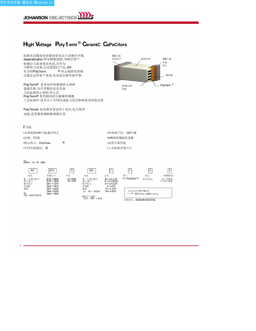
100%锡
外部端子
钯/银内部
电极
陶瓷坯体
100%锡
外部 终止
镍挡板
PolyTerm ®
F功能
•无铅端接100%锡,最后终止
•电极:钯/银
•核心终止:PolyTerm
®
•中间有阻隔层:镍
•外部端子层:100%锡 •NP0和X7R温度系数 •高度可靠性能 •工业标准封装尺寸
How to o rder
302
HigH V oltage P oly t erm ®a Vailability - X7r d ielectric
SIZE
1825
2220
2225
电压 500V630V10002V0003V0004V0005V0005V00V630V10002V0003V0004V0005V000XV1Y2500V630V10002V0003V0004V0005V000V
•'具有更高可用性和更短交货时间.
3
oltage P oly t erm ®a Vailability - X7r d ielectric
SIZE 0805
1206
1210
1808
1812
2211
电压 500V630V10005V00V630V10002V0003V0005V00V630V10002V0003V0005V00V630V10002V0003V0004V0005V000XV2Y3X1Y2500V630V10002V0003V0004V0005V000XV2Y3Y2
100 pF
150 pF
•
••
180 pF
220 pF
••
270 pF
330 pF
RE50分布式总线IO通用产品(产品手册)v0.1
RE50 分布式总线 IO 通用产品
产品手册
版本:V1.0 日期:2014.10
RE50 分布式总线 IO 通用产品手册
警告提示
为了您的人身安全以及避免财产损失,必须注意本手册中的提示。人身安全的提示用一个警告 三角表示,仅与财产损失有关的提示不带警告三角。警告提示根据危险等级由高到低,如下表 示。
小心
表示如果不采取相应的小心措施,可能导致轻微的人身伤害。
注意
表示如果不采取相应的小心措施,可能导致财产损失。 当出现多个危险等级的情况下,每次总是使用最高等级的警告提示。如果在某个警告提示中带
2 / 120
RE50 分布式总线 IO 通用产品手册
有警告可能导致人身伤害的警告三角,则可能在该警告提示中另外还附带有可能导致财产损失 的警告。
关于著作权及商标的记述
〉本手册的著作权归沈阳瑞德泰科电子有限公司所有。 〉绝对禁止对本书的随意复制。 〉其他公司及产品名是各公司的商标或注册商标。
责任免除
〉我们已对印刷品中所述内容与硬件和软件的一致性作过检查,但不排除存在偏差的可能性, 因此我们不保证印刷品中所述内容与硬件和软件完全一致。印刷品中的数据都按规定经过检测, 必要的修正值包含在下一版本中。 〉因商品改良,规格、外观及手册内容会有所更改,恕不另行通知,敬请谅解。
本手册目的............................................................................................................................................. 4 需要的基本知识..................................................................................................................................... 4 本手册适用范围..................................................................................................................................... 4 技术支持................................................................................................................................................. 4
EMC使用手册
04.AND R,A A&R->R
05.CLR R 0->R
06.CLRA 0->A
R /R->R
A R /R->A
09.DAA A寄存器调整为BCD值
49.NOP 空指令
50.OR A,K A OR K->A
51.RET [堆栈顶端]-》PC
52.RETI [堆栈顶端]-》PC使能中断
53.RETL K K->A [堆栈顶端]-》PC
54.SLEP 0->WDT, 振荡器停止振荡
7 6 5 4 3 2 1 0
DH7 PH6 PH5 PH4 PH3 PH2 PH1 PH0
7.IOCE_WTD控制寄存器
7 6 5 4 3 2 1 0
WTDE EIS - ROC - - - -
8.IOCF_中断屏蔽寄存器
7 6 5 4 3 2 1 0
- - - - - EXIE ICIE TCIE
三、指令
01.ADD A,R A+R->A
02.ADD R,A A+R->R
DP7 PD6 PD5 PD4 - PD2 PD1 PD0
5.IOCC_集电极开路控制寄存器
7 6 5 4 3 2 1 0
0D7 0D6 0D5 0D4 0D3 0D2 0D1 0D0
6.IOCD_上拉控制寄存器
6.R5—R6_分别为口5、口6的输入/输出寄存器
7.RF_中断状态寄存器
7 6 5 4 3 2 1 0
- - - - - EXIF ICIF TCIF
NED-50中文资料
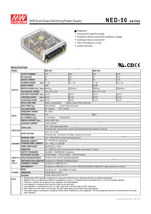
SPECIFICATIONMODELDC VOLTAGE RATED CURRENT CURRENT RANGE Note.6RATED POWEROUTPUTVOLTAGE ADJ. RANGE SETUP, RISE TIME HOLD TIME (Typ.)VOLTAGE RANGE FREQUENCY RANGEEFFICIENCY(Typ.)AC CURRENT (Typ.)INPUTINRUSH CURRENT (Typ.)LEAKAGE CURRENT SAFETY STANDARDS WORKING TEMP.WORKING HUMIDITYSTORAGE TEMP., HUMIDITYTEMP. COEFFICIENT VIBRATIONMTBFDIMENSION OTHERSNOTEPACKINGOVER LOAD500ms, 30ms/230VAC 1200ms, 30ms/115VAC at full load 50ms/230VAC 10ms/115VAC at full load85 ~ 264VAC 120 ~ 370VDC47 ~ 63Hz 1.1A/115VAC 0.65A/230VAC COLD START 45A <2mA / 240VAC110 ~ 150%rated output powerCompliance to EN55022 (CISPR22) Class B-20 ~ +60(Refer to output load derating curve)20 ~ 90% RH non-condensing-40 ~ +85, 10 ~ 95% RH 0.03%/(0 ~ 45)10 ~ 500Hz, 2G 10min./1cycle, period for 60min. each along X,Y, Z axes 413.3K hrs min. MIL-HDBK-217F (25)129*98*38mm (L*W*H)OVER VOLTAGE HARMONIC CURRENTEMS IMMUNITY Compliance to EN61000-3-2,-3Compliance to EN61000-4-2, 3, 4, 5, 6, 8,11, ENV50204, EN55024, EN61000-6-1 Light industry level, criteria AUniversal AC input/Full rangeProtections:Short circuit/Over load/Over voltage Cooling by free air convection 100% full load burn-in test 2 years warrantyFeatures :RIPPLE & NOISE (max.)Note.2VOLTAGE TOLERANCE Note.3EMI CONDUCTION & RADIATION ENVIRONMENT SAFETY &EMC(Note 6)PROTECTIONWITHSTAND VOLTAGEISOLATION RESISTANCE I/P-O/P:3KVAC I/P-FG:1.5KVAC O/P-FG:0.5KVACI/P-O/P, I/P-FG, O/P-FG:100M Ohms/500VDC1. All parameters NOT specially mentioned are measured at 230VAC input, rated load and 25of ambient temperature.2. Ripple & noise are measured at 20MHz of bandwidth by using a 12" twisted pair-wire terminated with a 0.1uf & 47uf parallel capacitor.3. Tolerance : includes set up tolerance, line regulation and load regulation.4. Line regulation is measured from low line to high line at rated load.5. Load regulation is measured from 20% to 100% rated load, and other output at 60% rated load.6. Each output can work within current range. But total output power can't exceed rated output power.7. The power supply is considered a component which will be installed into a final equipment. The final equipment must be re-confirmed that it still meets EMC directives.Protection type :Hiccup mode, recovers automatically after fault condition is removed NED-50A 5V 6A1 ~ 6A54W80mVp-p CH1: 4.75 ~ 5.5V2.0%0.5%1.5%CH1: 5.75 ~ 6.75V79%NED-50B12V CH224V CH25V CH12A 1.4A 4A 0.3 ~ 3A 0.2 ~ 2A1 ~ 6A 53.6W 120mVp-p 200mVp-p 80mVp-p CH1: 4.75 ~ 5.5V 6.0% 6.0%1.0% 1.0%3.0%3.0%2.0%0.5%1.5%82%LINE REGULATION Note.4LOAD REGULATION Note.5CH1OUTPUT NUMBER 0.44Kg; 45pcs/21Kg/1.24CUFTProtection type : Shut down o/p voltage, re-power on to recover UL60950-1, CB(IEC60950-1)ApprovedMechanical SpecificationCase No. 903 Unit:mmBlock DiagramCIRCUIT DETECTION O.L.P.EMI FILTERRECTIFIERS&FILTERPOWER SWITCH-FILTERFILTER&&RECTIFIERSRECTIFIERS+V1+V2COMI/PFGINGCONTROLO.V.P.Output Derating VS Input VoltageINPUT VOLTAGE (VAC) 60Hz8510095120115160140200180240220264L O A D (%)Ta=25901008070605040AMBIENT TEMPERATURE ()L O A D (%)-2002010304020408060100605070+V ADJ.fosc : 60KHzTerminal Pin. No AssignmentPin No.Pin No.1253467Assignment Assignment DC OUTPUT +V2DC OUTPUT COM DC OUTPUT +V1FG DC OUTPUT COMAC/L AC/N 8.212345679.5312-M3(HORIZONTAL)Derating Curve 97732383.59.5183-M328.54.573.51291206.518.53.53.5122.53.585.598337。
EMC45DRYI中文资料(List Unclassifed)中文数据手册「EasyDatasheet - 矽搜」

106.68 109.22 121.92 124.46 129.54 149.86
B
+_ 0.20
12.70 15.24 17.78 20.32 22.86
27.94 33.02 35.56 40.64 45.72 48.26
50.80 53.34 58.42 60.96 66.04 68.58
.275 [6.98]
.225 [5.72]
字母b SIDE
0.016 [0.41]厚, 总体PLATED ONLY
.007 [0.18] THICK
EYELET (TE)
EYELET (RE)
FITS .043 [1.09]
直角
(RA)
.125 [3.18]
.185 [4.70]
.050 [1.27]
C = PPS /铍镍(咨询工厂) N = PEEK /铍铜(咨询工厂) W = PEEK /铍镍(咨询工厂)
F = PPS / Pfinodal ***(咨询工厂)
咨询工厂其他材料
触点表面涂层
接触面
Z = 0.000010"金 X = 0.000030"金 G = 0.000010"金奖 Y = 0.000030"金奖
5.275 5.575
5.475 5.775
6.275 6.575
ቤተ መጻሕፍቲ ባይዱ
E
+_.020
1.275 1.375 1.475 1.575 1.675
1.875 2.075 2.175 2.375 2.575 2.675
2.775 2.875 3.075 3.175 3.375 3.475
Emc500说明书V2012EMC最新说明书模板
伏达仪器
-2-
前言
感谢您购买伏达仪器,在您使用本仪器之前,请首先确认下一页“装箱清 单”中所列的所有配件是否齐全,若发现配件不齐,或有错误,请尽快与我公 司或我们的代理商联系,以维护您的权益。
本仪器为精密电子仪器,为确保正确使用,以免使仪器遭到不必要的损坏, 在操作仪器之前请详细阅读本使用手册;请妥善保存本手册,以便遇到问题时 能及时查阅。
z EMC200A 单相模拟电源网络
功能 1、 采用国际标准规定的 50Ω/50μH+5Ω单相模拟电源网络。 2、 依据负载供电要求供电,范围:
1) 电压范围:AC 0-250V,DC 0-400V 2)电流范围:0-5A 3)频率范围:0-65Hz 3、前面板上设置测试相线或零线。
z EMC200B 单相模拟电源网络
规范的接收机(EMI Tester)有别于通用的频谱仪,CISPR 标准对 EMI 接 收机有专门的技术规范,只有按这种技术规范进行设计的仪器,才能准确测量, 满足各种标准测试的要求;而通用频谱仪不能满足规范要求,无法对各种干扰 波形实行准确测量。
我公司从 1997 年底就开始着手该仪器的研究工作,搜集国内外资料,引 进吸收了国外先进技术,采用了最新集成电路,成功地开发出 EMC500 接收机, 配合人工模拟电源网络、天线、功率吸收钳、耦合/去耦网络、电压探头等其 它相应设备,可以测量 9kHz-300MHz 频率范围内的各种电磁骚扰,满足 FCC, EN,GB 等国际、国内标准对电磁兼容的测试要求,并且价格相对较低。
本仪器广泛用于照明电器、家用电器、电动工具、开关电源等领域。
1.2 术语解释
EMI 接收机有别于通用的频谱分析仪,测得的电磁骚扰值一般用三种数据 表示:峰值、准峰值、平均值,它们含义如下:
EMC 资料
2
EMI
《信息技术设备的 无线电骚扰限值和 测量方法》 (有VGA 接口)
谐波电流发射限值 (设备每相输入电流 ≤16A 电压变化与闪烁测 试
GB9254 IEC/CISPR22 EN55022
GB17625.1 EN 61000-3-2 EN 61000-3-3
1.电源端传导骚扰电压测试 2.空间辐射骚扰场强测试
正常工作,相互之間不产生难以容忍的不良影响。 电磁骚扰的控制技术:
1>.电路设计:即將电路设计成既滿足功能要求又尽量减少电磁骚扰
的产生,尽量提高抗骚扰能力。(电路部分与结构部分) 2>.采用屏蔽技术,尽量减少空间辐射或耦合。 3>.采用合适的接地技术,解決安全及EMC问题。 4>.采用滤波技术,从頻域的角度,把不需要的頻率分量去除,从而在传 导乃至辐射两方面达到减少电磁骚扰的目的。 5>.展频技术。(针对Clock频率点,如LVDS、DDR)
是 *****
北美 欧洲
3
谐波 EMI
FLICKE R EMI
谐波电流
是****
同“1”
电压变化与闪烁 1.S1---S5 2.ESD 3.EFT 1.ESD 4. R/S 2.EFT 5. C/S 6. M/S 3.SURGE 7. DIPS
是* 是****
欧洲 欧洲
4
EMS
GB/T9383《声音和电视广播 接收机`和测量方法》 IEC/CISPR20 TV EN55020 《信息技术设备抗 扰度限值和测量方 法》 (有VGA接口) GB/T17618 IEC/CISPR24 EN55024
1. EMC发展
一、EMC发展:根据产品功能变化而变化; 1. 网络电视-----测试网络端口; 2. Wi-Fi 电视-----2.4G信号测试; 3. 2.4G 遥控器-----2.4G信号测试;
E+H 50W 电磁流量计操作说明书

BA 046D/06/en/04.00No. 50097090Valid as of software version:V 1.00.XX (amplifier)V 1.00.XX (communication)Promag 50电磁流量测量系统操作手册只有当满管时才能获得准确的测量.避免以下安装位置:易聚积气泡直接安装在一根向下的管线的敞开出口前以避免抽压而造成的对流量管衬里的破坏横隔膜或柱塞泵时需要在安装脉冲节气阀1.安装位置1.1安装向下管道当向下管道长度超过5m时以避免低压而可能造成的对测量管衬里的破坏减少含气量b=虹吸管非满管时倾斜非满管的管道并加泻放口检测管道为全空还是非充满有残渣聚积的场合最好能安装一个清洁阀1.2 安装方位垂直安装另外,针对不同的介质可选用如下有用的附件电极清洁回路(ECC)对于易粘附的介质可更换测量电极(EME)对于有磨损的介质这种方位对易自排空管道系统很理想,并可不加空管检测电极测量电极平面必须水平.这样可以防止由于夹带的气泡而产生的电极短时间绝缘空管检测功能仅当测量装置为水平安装及变送器外壳向上时能正确工作电压补偿)1.3振动如果振动剧烈注意抗振性和抗击性能指标请查有关章节基座,支撑如果公称直径为DN在能忍受足够负载的基座上安装变送器不允许利用外框承住传感器的重量如果可能,安装传感器最好避免例如阀门弯头等组件入口长度DN22.电气连接2.1分离型电气连接n.c.=电缆屏蔽层悬空2.1.1分离型电缆规格线圈电缆2约7mm)/km持久工作温度C约7mm)及单独屏蔽的芯带空管检测(EPD)约7mm)及单独屏蔽的芯导线阻抗/km420pF/m20...+70测量装置遵守EN61010,EN61326规定的EMC要求及NAMUR的建议NE21接地通过连接外壳里提供的接地端子222信号电缆:工作在有强烈电子干扰的区域2.2 测量单元电气连接2.2.1变送器(铝外壳)Fig.26变送器接线(铝外壳)a供电电源20...55VAC16...62VDC端子NO.1L+对DC端子NO.285...260VACL1对ACN对ACL-对DCb信号电缆端子NOs.20-27c保护导线的接地端d信号电缆屏蔽层接地端e服务连接头用于连接服务端口FAX193(Fieldcheck ,FieldTool)f夹头g接线腔罩导线截面积max.2.5mmTMTM2Fig.272.2.2 变送器(不锈钢外壳)变送器接线(不锈钢外壳)a供电电源16...62VDC端子NO.1L+对DC端子NO.2L-对DCb信号电缆端子NOs.20-27c保护导线的接地端d信号电缆屏蔽层接地端e服务连接头用于连接服务端口FAX193(Fieldcheck , FieldTool)f导线截面积85...260VAC20...55VACL1对ACN对ACmax.2.5mmTMTM2接线腔罩:::,,:,,::::,,,,::2.2.3 变送器(墙装式外壳)Fig.28:变送器接线(墙装式外壳)a供电电压: 16...62VDC端子NO.1L+对DC端子NO.2L-对DCb信号电缆端子NOs.20-27c保护导线的接地端d信号电缆屏蔽层接地端e服务连接头用于连接服务端口FAX193(Fieldcheck , FieldTool)f接线腔罩导线截面积85...260VAC20...55VACL1对ACN对ACmax.2.5mmTMTM2状态输入20-2122-2324-2526-27接线端状态输出状态输出频率输出电流输出HART电流输出HART电流输出HART输入/输出选型代码50***-***********W50***-***********A50***-***********D ,,,::,:2.2.5HART26/274...20mA 25CURRENT SPAN 4-20mA 4-20mA(25mA)HART HART 连接用户选择以下两种连接方式通过端子直接连至变送器通过电流输出信号连接注意:测量回路最小负载为调试后做如下设定功能或手操器连接HART a=HART b =C=d=PLC()手操器电气连接手操器电源屏蔽层其它设备或无源输入Fig.30:Commubox FXA191 a=PC带E+HCommuwin HART-DDE b=c=d =PLC()电气连接软件和服务器电源屏蔽层其它设备或无源输入CommuboxFXA191连接Ω→“ ”“ ”,,,,Ⅱ3.接地如果介质在无衬里并接地的金属管中流动,它可通过连3.1 标准接到变送器外壳而满足接地要求。
EMC基础知识总结,写的太全了!
EMC基础知识总结,写的太全了!传导与辐射电磁干扰(Electromagnetic Interference),简称EMI,有传导干扰和辐射干扰两种。
传导干扰主要是电子设备产生的干扰信号通过导电介质或公共电源线互相产生干扰。
辐射干扰是指电子设备产生的干扰信号通过空间耦合把干扰信号传给另一个电网络或电子设备。
为了防止一些电子产品产生的电磁干扰影响或破坏其它电子设备的正常工作,各国政府或一些国际组织都相继提出或制定了一些对电子产品产生电磁干扰有关规章或标准,符合这些规章或标准的产品就可称为具有电磁兼容性EMC(Electromagnetic Compatibility)。
电磁敏感度(Electromagnetic Susceptibility),简称EMS全称,指电子设备受电磁干扰的敏感程度。
电磁兼容(Electromagnetic Compatibility),简称EMC全称,要求电源模块等电子设备内部没有严重的干扰源及设备,或电源系统有较好的抗干扰能力。
它们的关系是:有了EMI也就有了EMC,满足EMS要求才能实现EMC,EMC测试是包含EMI和EMS的。
电磁兼容性EMC 标准不是恒定不变的,而是天天都在改变,这也是各国政府或经济组织,保护自己利益经常采取的手段。
EMC标准及测试国际标准1、国际电工委员为IEC2、国际标准华组织ISO3、电气电子工程师学会IEEE4、欧盟电信标准委员会ETSI5、国际无线电通信咨询委员CCIR6、国际通讯联盟ITU6、国际电工委员会IEC有以下分会进行EMC标准研究-CISPR:国际无线电干扰特别委员会-TC77:电气设备(包括电网)内电磁兼容技术委员会-TC65:工业过程测量和控制国际标准化组织1、FCC联邦通2、VDE德国电气工程师协会3、VCCI日本民间干扰 4、BS英国标准5、ABSI美国国家标准6、GOSTR 俄罗斯政府标准7、GB、GB/T中国国家标准EMI测试1、辐射骚扰电磁场(RE)2、骚扰功率(DP)3、传导骚扰(CE) 4、谐波电路(Harmonic)5、电压波动及闪烁(Flicker)6、瞬态骚扰电源(TDV)EMS测试1、辐射敏感度试验(RS)2、工频次次辐射敏感度试验(PMS)3、静电放电抗扰度(ESD) 4、射频场感应的传导骚扰抗扰度测试(CS)5、电压暂降,短时中断和电压变化抗扰度测试(DIP)6、浪涌(冲击)抗扰度测试(SURGE)7、电快速瞬变脉冲群抗扰度测试(EFT/B)8、电力线感应/接触(Power induction/contact)EMC测试结果的评价A级:实验中技术性能指标正常B级:试验中性能暂时降低,功能不丧失,实验后能自行恢复C级:功能允许丧失,但能自恢复,或操作者干预后能恢复R级:除保护元件外,不允许出现因设备(元件)或软件损坏数据丢失而造成不能恢复的功能丧失或性能降低。
EMC测试指导书
EMC测试指导书编写人员:杨继明工号:0807252M修订记录目录(报告完成后请更新)1概述 (5)1.1 试件名称、型号、版本及工作电压和电流 (5)1.2 测试性质 (5)1.3 采用标准、采用依据及测试项目列表 (5)1.4 辅助设备列表 (6)1.5 测试人员、参试人员 (6)1.6 测试部门、地点、时间 (6)2受试设备配置 (6)2.1 实物配置框图 (6)2.2 工作状态 (7)2.3 测试组网 (7)2.4 结构描述 (7)2.5 单板配置 (7)2.6 接口及接口电缆配置 (7)2.7 抗扰度说明 (8)2.7.1 监控信息 (8)2.7.2 抗扰度判据 (8)3总结和评价 (8)3.1 测试充分性评价 (8)3.2 测试差异说明 (8)3.3 测试项目通过清单 (9)3.4 问题及相关对策 (9)3.4.1 问题描述 (9)3.4.2 对策描述 (10)4测试内容 (10)4.1 电磁骚扰测试 (10)4.1.1 测试任务1——辐射骚扰测试(RE) (10)4.1.2 测试任务2—传导骚扰测试(CE) (13)4.1.3 测试任务3——谐波电流骚扰测试(Harmonic) (16)4.1.4 测试任务4 ——电压波动与闪烁测试(Fluctuations and flicker) (17)4.2 电磁抗扰度测试 (18)4.2.1 测试任务1——射频电磁场辐射抗扰度测试(RS) (18)4.2.2 测试任务2——传导骚扰抗扰度测试(CS) (19)4.2.3 测试任务3——电快速瞬变脉冲群抗扰度测试(EFT/B) (21)4.2.4 测试任务4——静电放电抗扰度测试(ESD) (22)4.2.5 测试任务5——电压跌落、短时中断与电压缓变抗扰度测试(DIP/interruption 〕 (24)4.2.6 测试任务6——浪涌抗扰度测试(SURGE) (25)4.2.7 测试任务7——工频磁场抗扰度测试(PMS) (29)附录一:相关测试仪器信息 (32)附录二:测试仪器不确定度: (34)附录三:骚扰测试曲线和数据: (35)附录四:测试布置照片: .............................................................................. 错误!未定义书签。
REF5050ID中文资料
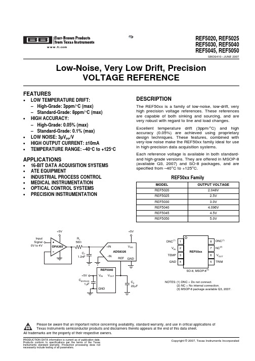
FEATURESDESCRIPTION APPLICATIONSInput Signal 0V to 4V12348765DNC(1)NC(2)TRIMDNC(1)V INTEMPGNDV OUTREF50xxSO-8, MSOP-8(3)(1) DNC = Do not connect.(2) NC = No internal connection.(3) MSOP-8 package available Q3, 2007.NOTES:REF5020,,REF5025REF5030,REF5040 REF5045,REF5050SBOS410–JUNE2007 Low-Noise,Very Low Drift,PrecisionVOLTAGE REFERENCE•LOW TEMPERATURE DRIFT:–High-Grade:3ppm/°C(max)The REF50xx is a family of low-noise,low-drift,veryhigh precision voltage references.These references –Standard-Grade:8ppm/°C(max)are capable of both sinking and sourcing,and are •HIGH ACCURACY:very robust with regard to line and load changes.–High-Grade:0.05%(max)Excellent temperature drift(3ppm/°C)and high –Standard-Grade:0.1%(max)accuracy(0.05%)are achieved using proprietary •LOW NOISE:3μV PP/V design techniques.These features,combined withvery-low noise make the REF50xx family ideal for use •HIGH OUTPUT CURRENT:±10mAin high-precision data acquisition systems.•TEMPERATURE RANGE:–40°C to+125°CEach reference voltage is available in both standard-and high-grade versions.They are offered in MSOP-8(available Q3,2007)and SO-8packages,and are •16-BIT DATA ACQUISITION SYSTEMSspecified from–40°C to+125°C.•ATE EQUIPMENT•INDUSTRIAL PROCESS CONTROL REF50xx Family•MEDICAL INSTRUMENTATION MODEL OUTPUT VOLTAGE •OPTICAL CONTROL SYSTEMS REF5020 2.048V •PRECISION INSTRUMENTATION REF5025 2.5VREF5030 3.0VREF5040 4.096VREF5045 4.5VREF5050 5.0VPlease be aware that an important notice concerning availability,standard warranty,and use in critical applications ofTexas Instruments semiconductor products and disclaimers thereto appears at the end of this data sheet.All trademarks are the property of their respective owners.ABSOLUTE MAXIMUM RATINGS (1)REF5020,,REF5025REF5030,REF5040REF5045,REF5050SBOS410–JUNE 2007This integrated circuit can be damaged by ESD.Texas Instruments recommends that all integrated circuits be handled with appropriate precautions.Failure to observe proper handling and installation procedures can cause damage.ESD damage can range from subtle performance degradation to complete device failure.Precision integrated circuits may be more susceptible to damage because very small parametric changes could cause the device not to meet its published specifications.PACKAGE/ORDERING INFORMATION (1)(1)For the most current package and ordering information see the Package Option Addendum at the end of this document,or see the TI web site at .(2)MSOP-8(DGK)package available Q3,2007.PARAMETER REF50xx UNIT Input Voltage +18V Output Short-Circuit30mA Operating Temperature Range –55to +125°C Storage Temperature Range –55to +150°C Junction Temperature (T J max)+150°C Human Body Model (HBM)3000V ESD Rating Charged Device Model (CDM)1000V(1)Stresses above these ratings may cause permanent damage.Exposure to absolute maximum conditions for extended periods may degrade device reliability.These are stress ratings only,and functional operation of the device at these or any other conditions beyond those specified is not implied.ELECTRICAL CHARACTERISTICS:PER DEVICE REF5020,,REF5025 REF5030,REF5040 REF5045,REF5050SBOS410–JUNE2007Boldface limits apply over the specified temperature range,T A=–40°C to+125°C.At T A=+25°C,I LOAD=0,C L=1μF,and V IN=(V OUT+0.2V)to18V,unless otherwise noted.PER DEVICE PARAMETER CONDITIONS MIN TYP MAX UNITREF5020(V OUT=2.048V)(1)OUTPUT VOLTAGEOutput Voltage V OUT 2.7V<V IN<18V 2.048V Initial Accuracy:High-Grade–0.050.05% Standard-Grade–0.10.1% NOISEOutput Voltage Noise f=0.1Hz to10Hz6μV PPREF5025(V OUT=2.5V)OUTPUT VOLTAGEOutput Voltage V OUT 2.5V Initial Accuracy:High-Grade–0.050.05% Standard-Grade–0.10.1% NOISEOutput Voltage Noise f=0.1Hz to10Hz7.5μV PPREF5030(V OUT=3.0V)OUTPUT VOLTAGEOutput Voltage V OUT 3.0V Initial Accuracy:High-Grade–0.050.05% Standard-Grade–0.10.1% NOISEOutput Voltage Noise f=0.1Hz to10Hz9μV PPREF5040(V OUT=4.096V)OUTPUT VOLTAGEOutput Voltage V OUT 4.096V Initial Accuracy:High-Grade–0.050.05% Standard-Grade–0.10.1% NOISEOutput Voltage Noise f=0.1Hz to10Hz12μV PPREF5045(V OUT=4.5V)OUTPUT VOLTAGEOutput Voltage V OUT 4.5V Initial Accuracy:High-Grade–0.050.05% Standard-Grade–0.10.1% NOISEOutput Voltage Noise f=0.1Hz to10Hz13.5μV PPREF5050(V OUT=5.0V)OUTPUT VOLTAGEOutput Voltage V OUT 5.0V Initial Accuracy:High-Grade–0.050.05% Standard-Grade–0.10.1% NOISEOutput Voltage Noise f=0.1Hz to10Hz15μV PP (1)For V OUT≤2.5V,the minimum supply voltage is2.7V.ELECTRICAL CHARACTERISTICS:ALL DEVICESREF5020,,REF5025REF5030,REF5040REF5045,REF5050SBOS410–JUNE 2007Boldface limits apply over the specified temperature range,T A =–40°C to +125°C.At T A =+25°C,I LOAD =0,C L =1μF,and V IN =(V OUT +0.2V)to 18V,unless otherwise noted.REF50xxPARAMETERCONDITIONSMIN TYP MAX UNITOUTPUT VOLTAGE TEMPERATURE DRIFT Output Voltage Temperature Drift dV OUT /dTHigh-Grade 2.53ppm/°C Standard-Grade 38ppm/°CLINE REGULATION Line Regulation dV OUT /dV INREF5020(1)Only V IN =2.7V to 18V0.11ppm/V All Other Devices 0.11ppm/V Over Temperature 0.21ppm/V LOAD REGULATION Load Regulation dV OUT /d ILOAD–10mA <I LOAD <+10mA,V IN =V OUT +0.75V2030ppm/mA Over Temperature 50ppm/mA SHORT-CIRCUIT CURRENT Short-Circuit Current I SC V OUT =025mA TEMP PIN Voltage OutputAt T A =+25°C575mV Temperature Sensitivity 2.64mV/°C TURN-ON SETTLING TIME Turn-On Settling Time To 0.1%with C L =1μF200μsPOWER SUPPLY Supply Voltage V SSee Note(1)V OUT +0.2(1)18V Quiescent Current 0.81mA Over Temperature 1.2mATEMPERATURE RANGE Specified Range –40+125°C Operating Range –55+125°CThermal Resistance θJAMSOP-8150°C/W SO-8150°C/W(1)For V OUT ≤2.5V,the minimal supply voltage is 2.7V.TYPICAL CHARACTERISTICS0.20.50.71.01.21.51.72.02.22.52.73.03.23.53.74.04.24.54.75.0Drift (ppm/C)°P o p u l a t i o n (%)0.51.01.52.02.53.03.54.04.55.05.56.06.57.07.58.0Drift (ppm/C)°P o p u l a t i o n (%)-50-25T emperature (C)°0.050.040.030.020.010-0.01-0.02-0.03-0.04-0.05O u t p u tV o l t a g e A c c u r a c y (%)125255075100-0.0-0.0-0.0-0.0-0.00.00.00.00.00.0Drift (ppm/C)°P o p u l a t i o n (%)10Frequency (Hz)160140120100806040200P S R R (d B )100k1001k10k-15-10-5Load Current (mA)0.80.70.60.50.40.30.20.10D r o p o u t V o l t a g e (V )150510+125C°+25C °-°40CREF5020,,REF5025REF5030,REF5040REF5045,REF5050SBOS410–JUNE 2007At T A =+25°C,I LOAD =0,and V S =V OUT +0.2V,unless otherwise noted.For V OUT ≤2.5V,the minimum supply voltage is 2.7V.TEMPERATURE DRIFTTEMPERATURE DRIFT (0°C to +85°C)(–40°C to +125°C)Figure 1.Figure 2.OUTPUT VOLTAGE OUTPUT VOLTAGE ACCURACYINITIAL ACCURACYvs TEMPERATUREFigure 3.Figure 4.POWER-SUPPLY REJECTION RATIOvs FREQUENCYDROPOUT VOLTAGE vs LOAD CURRENTFigure 5.Figure 6.-10-5Load Current (mA)2.501252.501002.500752.500502.500252.500002.499752.499502.499252.499002.49875O u t p u t V o l t a g e (V )105+125C°+25C°-°40C -50-25T emperature (C)°0.90.80.70.60.50.40.3T E M P P i n O u t p u t V o l t a g e (V )125255075100-50-25T emperature (C)°10501000950900850800750700650600Q u i e s c e n t C u r r e n t (m A )125255075100-50-25T emperature (C)°0.50.40.30.20.10-0.1-0.2-0.3-0.4-0.5L i n e R e g u l a t i o n (p p m /V )1252550751001s/div1V /d i vm -50-25T emperature (C)°35302520151050S h o r t -C i r c u i t C u r r e n t (m A )125255075100REF5020,,REF5025REF5030,REF5040REF5045,REF5050SBOS410–JUNE 2007TYPICAL CHARACTERISTICS (continued)At T A =+25°C,I LOAD =0,and V S =V OUT +0.2V,unless otherwise noted.For V OUT ≤2.5V,the minimum supply voltage is 2.7V.REF5025OUTPUT VOLTAGETEMP PIN OUTPUT VOLTAGEvs LOAD CURRENTvs TEMPERATUREFigure 7.Figure 8.QUIESCENT CURRENT LINE REGULATION vs TEMPERATUREvs TEMPERATUREFigure 9.Figure 10.SHORT-CIRCUIT CURRENTvs TEMPERATURENOISEFigure 11.Figure 12.40s/div m 2V/div1V/divV OUTV IN400s/divm 5V/div1V/divV OUTV IN20s/div m -1mA-1mA+1mAI LOADV OUT5mV/div1mA/div20s/divm -10mA+10mA+10mAI LOAD V OUT2mV/div10mA/div100s/div m -1mA-1mA+1mAI LOAD V OUT5mV/div1mA/div100s/divm -10mA-10mA+10mAI LOAD V OUT2mV/div10mA/divREF5020,,REF5025REF5030,REF5040REF5045,REF5050SBOS410–JUNE 2007TYPICAL CHARACTERISTICS (continued)At T A =+25°C,I LOAD =0,and V S =V OUT +0.2V,unless otherwise noted.For V OUT ≤2.5V,the minimum supply voltage is 2.7V.STARTUPSTARTUP(REF5025,C =1μF)(REF5025,C =10μF)Figure 13.Figure 14.LOAD TRANSIENT LOAD TRANSIENT (C L =1μF,I OUT =1mA)(C L =1μF,I OUT =10mA)Figure 15.Figure 16.LOAD TRANSIENT LOAD TRANSIENT (C L =10μF,I OUT =1mA)(C L =10μF,I OUT =10mA)Figure 17.Figure 18.20m s/div V OUTV IN5mV/div500mV/div100s/divm V OUTV IN5mV/div500mV/divREF5020,,REF5025REF5030,REF5040REF5045,REF5050SBOS410–JUNE 2007TYPICAL CHARACTERISTICS (continued)At T A =+25°C,I LOAD =0,and V S =V OUT +0.2V,unless otherwise noted.For V OUT ≤2.5V,the minimum supply voltage is 2.7V.LINE TRANSIENTLINE TRANSIENT (C L =1μF)(C L =10μF)Figure 19.Figure 20.APPLICATION INFORMATIONSUPPLY VOLTAGEOUTPUT ADJUSTMENT (TRIM Pin)BASIC CONNECTIONSTEMPERATURE DRIFTDrift +ǒVOUTMAX*V OUTMINV OUT Temp RangeǓ106(ppm)(1)REF5020,,REF5025REF5030,REF5040REF5045,REF5050SBOS410–JUNE 2007The REF50xx is family of low-noise,precision bandgap voltage references that are specifically designed for excellent initial voltage accuracy and The REF50xx family of voltage references features drift.Figure 21shows a simplified block diagram of extremely low dropout voltage.With the exception of the REF50xx.the REF5020,which has a minimum supply requirement of 2.7V,these references can be operated with a supply of 200mV above the output voltage in an unloaded condition.For loaded conditions,a typical dropout voltage versus load plot is shown in Figure 6of the Typical Characteristics.The REF50xx provides a very accurate voltage output.However,V OUT can be adjusted from the nominal value for the purpose of trimming system errors by configuring the TRIM pin (pin 5).The TRIM pin provides for adjustment of the voltage at V OUT over a ±15mV range.Figure 23shows a typical circuit using the TRIM pin to adjust V OUT .When using this technique,the temperature coefficients of the resistors can degrade the temperature drift at the output.Figure 21.REF50xx Simplified Block DiagramFigure 22shows the typical connections for the REF50xx.A supply bypass capacitor ranging between 1μF to 10μF is recommended.A 1μF to 50μF,low-ESR output capacitor (C L )must be connected to V OUT .Figure 23.V OUT Adjustment Using the TRIM PinThe REF50xx is designed for minimal drift error,which is defined as the change in output voltage over temperature.The drift is calculated using the box method,as described by the following equation:Figure 22.Basic ConnectionsThe REF50xx features a maximum drift coefficient of 3ppm/°C for the high-grade version,and 8ppm/°C for the standard-grade.TEMPERATURE MONITORINGPOWER DISSIPATIONNOISE PERFORMANCEREF5020,,REF5025REF5030,REF5040REF5045,REF5050SBOS410–JUNE 2007The temperature output terminal (TEMP,pin 3)The REF50xx family is specified to deliver current provides a temperature-dependent voltage output loads of ±10mA over the specified input voltage with approximately 60k Ωsource impedance.As seen range.The temperature of the device increases in Figure 8,the output voltage follows the nominal according to the equation:relationship:T J =T A +P D ×θJAV TEMPPIN=509mV +2.64×T(°C)Where:T J =Junction temperature (°C)This pin indicates general chip temperature,accurate to approximately ±15°C.Although it is not generally T A =Ambient temperature (°C)suitable for accurate temperature measurements,it P D =Power dissipated (W)can be used to indicate temperature changes or for θJA =Junction-to-ambient thermal resistance temperature compensation of analog circuitry.A (°C/W)temperature change of 30°C corresponds to an approximate 79mV change in voltage at the TEMP The REF50xx junction temperature must not exceed pin.the absolute maximum rating of +150°C.The TEMP pin has high output impedance (see Figure 21).Loading this pin with a low-impedance circuit induces a measurement error;however,it does Typical 0.1Hz to 10Hz voltage noise for each member not have any effect on V OUT accuracy.To avoid of the REF50xx family is specified in the Electrical errors caused by low-impedance loading,buffer the Characteristics:Per Device table.The noise voltage TEMP pin output with a suitable low-temperature drift increases with output voltage and operating op amp,such as the OPA333,OPA335,or OPA376,temperature.Additional filtering can be used to as shown in Figure 24.improve output noise levels,although care should be taken to ensure the output impedance does not degrade performance.Figure 24.Buffering the TEMP Pin OutputAPPLICATION CIRCUITSDATA ACQUISITIONNEGATIVE REFERENCE VOLTAGEREF5020,,REF5025REF5030,REF5040REF5045,REF5050SBOS410–JUNE 2007Data acquisition systems often require stable voltage For applications requiring a negative and positive references to maintain accuracy.The REF50xx family reference voltage,the REF50xx and OPA735can be features low noise,very low drift,and high initial used to provide a dual-supply reference from a 5V accuracy for high-performance data converters.supply.Figure 25shows the REF5025used to Figure 26shows the REF5040in a basic data provide a 2.5V supply reference voltage.The low drift acquisition system.performance of the REF50xx complements the low offset voltage and zero drift of the OPA735to provide an accurate solution for split-supply applications.Care must be taken to match the temperature coefficients of R 1and R 2.Figure 26.Basic Data Acquisition SystemFigure 25.The REF5025and OPA735Create Positive and Negative Reference VoltagesPACKAGING INFORMATIONOrderableDevice Status (1)Package Type Package DrawingPins Package Qty Eco Plan (2)Lead/Ball Finish MSL Peak Temp (3)REF5020AID ACTIVE SOIC D 875Green (RoHS &no Sb/Br)CU NIPDAU Level-2-260C-1YEAR REF5020AIDG4ACTIVE SOIC D 875Green (RoHS &no Sb/Br)CU NIPDAU Level-2-260C-1YEAR REF5020AIDR ACTIVE SOIC D 82500Green (RoHS &no Sb/Br)Call TI Level-2-260C-1YEAR REF5020AIDRG4ACTIVE SOIC D 82500Green (RoHS &no Sb/Br)Call TI Level-2-260C-1YEAR REF5020ID ACTIVE SOIC D 875Green (RoHS &no Sb/Br)CU NIPDAU Level-2-260C-1YEAR REF5020IDG4ACTIVE SOIC D 875Green (RoHS &no Sb/Br)CU NIPDAU Level-2-260C-1YEAR REF5020IDR ACTIVE SOIC D 82500Green (RoHS &no Sb/Br)CU NIPDAU Level-2-260C-1YEAR REF5020IDRG4ACTIVE SOIC D 82500Green (RoHS &no Sb/Br)CU NIPDAU Level-2-260C-1YEAR REF5025AID ACTIVE SOIC D 875Green (RoHS &no Sb/Br)CU NIPDAU Level-2-260C-1YEAR REF5025AIDG4ACTIVE SOIC D 875Green (RoHS &no Sb/Br)CU NIPDAU Level-2-260C-1YEAR REF5025AIDR ACTIVE SOIC D 82500Green (RoHS &no Sb/Br)Call TI Level-2-260C-1YEAR REF5025AIDRG4ACTIVE SOIC D 82500Green (RoHS &no Sb/Br)Call TI Level-2-260C-1YEAR REF5025ID ACTIVE SOIC D 875Green (RoHS &no Sb/Br)CU NIPDAU Level-2-260C-1YEAR REF5025IDG4ACTIVE SOIC D 875Green (RoHS &no Sb/Br)CU NIPDAU Level-2-260C-1YEAR REF5025IDR ACTIVE SOIC D 82500Green (RoHS &no Sb/Br)CU NIPDAU Level-2-260C-1YEAR REF5025IDRG4ACTIVE SOIC D 82500Green (RoHS &no Sb/Br)CU NIPDAU Level-2-260C-1YEAR REF5030AID ACTIVE SOIC D 875Green (RoHS &no Sb/Br)CU NIPDAU Level-2-260C-1YEAR REF5030AIDG4ACTIVE SOIC D 875Green (RoHS &no Sb/Br)CU NIPDAU Level-2-260C-1YEAR REF5030AIDR ACTIVE SOIC D 82500Green (RoHS &no Sb/Br)Call TI Level-2-260C-1YEAR REF5030AIDRG4ACTIVE SOIC D 82500Green (RoHS &no Sb/Br)Call TI Level-2-260C-1YEAR REF5030ID ACTIVE SOIC D 875Green (RoHS &no Sb/Br)CU NIPDAU Level-2-260C-1YEAR REF5030IDG4ACTIVE SOIC D 875Green (RoHS &no Sb/Br)CU NIPDAU Level-2-260C-1YEAR REF5030IDR ACTIVE SOIC D 82500Green (RoHS &no Sb/Br)CU NIPDAU Level-2-260C-1YEAR REF5030IDRG4ACTIVE SOIC D 82500Green (RoHS &no Sb/Br)CU NIPDAU Level-2-260C-1YEAR REF5040AIDACTIVESOICD875Green (RoHS &no Sb/Br)CU NIPDAULevel-2-260C-1YEAR12-Oct-2007Orderable Device Status (1)Package Type Package DrawingPins Package Qty Eco Plan (2)Lead/Ball Finish MSL Peak Temp (3)REF5040AIDG4ACTIVE SOIC D 875Green (RoHS &no Sb/Br)CU NIPDAU Level-2-260C-1YEAR REF5040AIDR ACTIVE SOIC D 82500Green (RoHS &no Sb/Br)Call TI Level-2-260C-1YEAR REF5040AIDRG4ACTIVE SOIC D 82500Green (RoHS &no Sb/Br)Call TI Level-2-260C-1YEAR REF5040ID ACTIVE SOIC D 875Green (RoHS &no Sb/Br)CU NIPDAU Level-2-260C-1YEAR REF5040IDG4ACTIVE SOIC D 875Green (RoHS &no Sb/Br)CU NIPDAU Level-2-260C-1YEAR REF5040IDR ACTIVE SOIC D 82500Green (RoHS &no Sb/Br)CU NIPDAU Level-2-260C-1YEAR REF5040IDRG4ACTIVE SOIC D 82500Green (RoHS &no Sb/Br)CU NIPDAU Level-2-260C-1YEAR REF5045AID ACTIVE SOIC D 875Green (RoHS &no Sb/Br)CU NIPDAU Level-2-260C-1YEAR REF5045AIDG4ACTIVE SOIC D 875Green (RoHS &no Sb/Br)CU NIPDAU Level-2-260C-1YEAR REF5045AIDR ACTIVE SOIC D 82500Green (RoHS &no Sb/Br)Call TI Level-2-260C-1YEAR REF5045AIDRG4ACTIVE SOIC D 82500Green (RoHS &no Sb/Br)Call TI Level-2-260C-1YEAR REF5045ID ACTIVE SOIC D 875Green (RoHS &no Sb/Br)CU NIPDAU Level-2-260C-1YEAR REF5045IDG4ACTIVE SOIC D 875Green (RoHS &no Sb/Br)CU NIPDAU Level-2-260C-1YEAR REF5045IDR ACTIVE SOIC D 82500Green (RoHS &no Sb/Br)CU NIPDAU Level-2-260C-1YEAR REF5045IDRG4ACTIVE SOIC D 82500Green (RoHS &no Sb/Br)CU NIPDAU Level-2-260C-1YEAR REF5050AID ACTIVE SOIC D 875Green (RoHS &no Sb/Br)CU NIPDAU Level-2-260C-1YEAR REF5050AIDG4ACTIVE SOIC D 875Green (RoHS &no Sb/Br)CU NIPDAU Level-2-260C-1YEAR REF5050AIDR ACTIVE SOIC D 82500Green (RoHS &no Sb/Br)Call TI Level-2-260C-1YEAR REF5050AIDRG4ACTIVE SOIC D 82500Green (RoHS &no Sb/Br)Call TI Level-2-260C-1YEAR REF5050ID ACTIVE SOIC D 875Green (RoHS &no Sb/Br)CU NIPDAU Level-2-260C-1YEAR REF5050IDG4ACTIVE SOIC D 875Green (RoHS &no Sb/Br)CU NIPDAU Level-2-260C-1YEAR REF5050IDR ACTIVE SOIC D 82500Green (RoHS &no Sb/Br)CU NIPDAU Level-2-260C-1YEAR REF5050IDRG4ACTIVESOICD82500Green (RoHS &no Sb/Br)CU NIPDAULevel-2-260C-1YEAR(1)The marketing status values are defined as follows:ACTIVE:Product device recommended for new designs.LIFEBUY:TI has announced that the device will be discontinued,and a lifetime-buy period is in effect.NRND:Not recommended for new designs.Device is in production to support existing customers,but TI does not recommend using this part in a new design.PREVIEW:Device has been announced but is not in production.Samples may or may not be available.12-Oct-2007OBSOLETE:TI has discontinued the production of the device.(2)Eco Plan -The planned eco-friendly classification:Pb-Free (RoHS),Pb-Free (RoHS Exempt),or Green (RoHS &no Sb/Br)-please check /productcontent for the latest availability information and additional product content details.TBD:The Pb-Free/Green conversion plan has not been defined.Pb-Free (RoHS):TI's terms "Lead-Free"or "Pb-Free"mean semiconductor products that are compatible with the current RoHS requirements for all 6substances,including the requirement that lead not exceed 0.1%by weight in homogeneous materials.Where designed to be soldered at high temperatures,TI Pb-Free products are suitable for use in specified lead-free processes.Pb-Free (RoHS Exempt):This component has a RoHS exemption for either 1)lead-based flip-chip solder bumps used between the die and package,or 2)lead-based die adhesive used between the die and leadframe.The component is otherwise considered Pb-Free (RoHS compatible)as defined above.Green (RoHS &no Sb/Br):TI defines "Green"to mean Pb-Free (RoHS compatible),and free of Bromine (Br)and Antimony (Sb)based flame retardants (Br or Sb do not exceed 0.1%by weight in homogeneous material)(3)MSL,Peak Temp.--The Moisture Sensitivity Level rating according to the JEDEC industry standard classifications,and peak solder temperature.Important Information and Disclaimer:The information provided on this page represents TI's knowledge and belief as of the date that it is provided.TI bases its knowledge and belief on information provided by third parties,and makes no representation or warranty as to the accuracy of such information.Efforts are underway to better integrate information from third parties.TI has taken and continues to take reasonable steps to provide representative and accurate information but may not have conducted destructive testing or chemical analysis on incoming materials and chemicals.TI and TI suppliers consider certain information to be proprietary,and thus CAS numbers and other limited information may not be available for release.In no event shall TI's liability arising out of such information exceed the total purchase price of the TI part(s)at issue in this document sold by TI to Customer on an annualbasis.12-Oct-2007TAPE AND REEL BOXINFORMATIONDevicePackage Pins SiteReel Diameter (mm)Reel Width (mm)A0(mm)B0(mm)K0(mm)P1(mm)W (mm)Pin1Quadrant REF5020AIDR D 8SITE 4133012 6.4 5.2 2.1812Q1REF5020IDR D 8SITE 4133012 6.4 5.2 2.1812Q1REF5025AIDR D 8SITE 4133012 6.4 5.2 2.1812Q1REF5025IDR D 8SITE 4133012 6.4 5.2 2.1812Q1REF5030AIDR D 8SITE 4133012 6.4 5.2 2.1812Q1REF5030IDR D 8SITE 4133012 6.4 5.2 2.1812Q1REF5040AIDR D 8SITE 4133012 6.4 5.2 2.1812Q1REF5040IDR D 8SITE 4133012 6.4 5.2 2.1812Q1REF5045AIDR D 8SITE 4133012 6.4 5.2 2.1812Q1REF5045IDR D 8SITE 4133012 6.4 5.2 2.1812Q1REF5050AIDR D 8SITE 4133012 6.4 5.2 2.1812Q1REF5050IDRD8SITE 41330126.45.22.1812Q17-Nov-2007DevicePackagePins Site Length (mm)Width (mm)Height (mm)REF5020AIDR D 8SITE 41346.0346.029.0REF5020IDR D 8SITE 41346.0346.029.0REF5025AIDR D 8SITE 41346.0346.029.0REF5025IDR D 8SITE 41346.0346.029.0REF5030AIDR D 8SITE 41346.0346.029.0REF5030IDR D 8SITE 41346.0346.029.0REF5040AIDR D 8SITE 41346.0346.029.0REF5040IDR D 8SITE 41346.0346.029.0REF5045AIDR D 8SITE 41346.0346.029.0REF5045IDR D 8SITE 41346.0346.029.0REF5050AIDR D 8SITE 41346.0346.029.0REF5050IDRD8SITE 41346.0346.029.07-Nov-2007IMPORTANT NOTICETexas Instruments Incorporated and its subsidiaries(TI)reserve the right to make corrections,modifications,enhancements, improvements,and other changes to its products and services at any time and to discontinue any product or service without notice. Customers should obtain the latest relevant information before placing orders and should verify that such information is current and complete.All products are sold subject to TI’s terms and conditions of sale supplied at the time of order acknowledgment.TI warrants performance of its hardware products to the specifications applicable at the time of sale in accordance with TI’s standard warranty.Testing and other quality control techniques are used to the extent TI deems necessary to support this warranty.Except where mandated by government requirements,testing of all parameters of each product is not necessarily performed.TI assumes no liability for applications assistance or customer product design.Customers are responsible for their products and applications using TI components.To minimize the risks associated with customer products and applications,customers should provide adequate design and operating safeguards.TI does not warrant or represent that any license,either express or implied,is granted under any TI patent right,copyright,mask work right,or other TI intellectual property right relating to any combination,machine,or process in which TI products or services are rmation published by TI regarding third-party products or services does not constitute a license from TI to use such products or services or a warranty or endorsement e of such information may require a license from a third party under the patents or other intellectual property of the third party,or a license from TI under the patents or other intellectual property of TI. Reproduction of TI information in TI data books or data sheets is permissible only if reproduction is without alteration and is accompanied by all associated warranties,conditions,limitations,and notices.Reproduction of this information with alteration is an unfair and deceptive business practice.TI is not responsible or liable for such altered rmation of third parties may be subject to additional restrictions.Resale of TI products or services with statements different from or beyond the parameters stated by TI for that product or service voids all express and any implied warranties for the associated TI product or service and is an unfair and deceptive business practice.TI is not responsible or liable for any such statements.TI products are not authorized for use in safety-critical applications(such as life support)where a failure of the TI product would reasonably be expected to cause severe personal injury or death,unless officers of the parties have executed an agreement specifically governing such use.Buyers represent that they have all necessary expertise in the safety and regulatory ramifications of their applications,and acknowledge and agree that they are solely responsible for all legal,regulatory and safety-related requirements concerning their products and any use of TI products in such safety-critical applications,notwithstanding any applications-related information or support that may be provided by TI.Further,Buyers must fully indemnify TI and its representatives against any damages arising out of the use of TI products in such safety-critical applications.TI products are neither designed nor intended for use in military/aerospace applications or environments unless the TI products are specifically designated by TI as military-grade or"enhanced plastic."Only products designated by TI as military-grade meet military specifications.Buyers acknowledge and agree that any such use of TI products which TI has not designated as military-grade is solely at the Buyer's risk,and that they are solely responsible for compliance with all legal and regulatory requirements in connection with such use.TI products are neither designed nor intended for use in automotive applications or environments unless the specific TI products are designated by TI as compliant with ISO/TS16949requirements.Buyers acknowledge and agree that,if they use anynon-designated products in automotive applications,TI will not be responsible for any failure to meet such requirements. Following are URLs where you can obtain information on other Texas Instruments products and application solutions:Products ApplicationsAmplifiers Audio /audioData Converters Automotive /automotiveDSP Broadband /broadbandInterface Digital Control /digitalcontrolLogic Military /militaryPower Mgmt Optical Networking /opticalnetworkMicrocontrollers Security /securityRFID Telephony /telephonyLow Power /lpw Video&Imaging /videoWirelessWireless /wirelessMailing Address:Texas Instruments,Post Office Box655303,Dallas,Texas75265Copyright©2007,Texas Instruments Incorporated。
EMC,ESD相关基础知识资料
EMCEMC,ESD资料就结构设计考虑EMC谈几点自己的看法EMC是近代发展起来的新的学科领域。
随着科学技术的发展,电磁兼容在现代科技中的作用与地位日益提高,它已成为有关工程技术人员必备的专业知识。
EMC问题贯穿于一个产品的全部过程。
从系统设计,电路设计,结构设计,工艺设计,产品生产。
无不与之相关。
由于我在原单位从事的是产品工艺,这里愿意结构设计员就EMC问题一起讨论。
先谈几点自己的看法。
1.薄膜屏蔽。
现代电子中广泛采用了工程塑料作为机箱,它具有加工工艺性能好,造型美观、成本低、重量轻等优点。
为了具备电磁屏蔽的功能,通常采用喷导电漆、电弧喷涂、电镀、化学镀、贴导电薄膜等工艺。
假定导电薄膜的厚度为l,电磁波在导电薄膜中的波长为λ,若l<λ/4则为薄膜屏蔽。
下面介绍几种常用方法在1MHz和1GHz频段时的屏蔽效能:方法厚度(μm)表阻屏蔽效能(dB)锌电弧喷涂 12-25 0.03 50-60锌火喷涂 25 4 40镍基镀层 50 0.5-2.0 30-75银基镀层 25 0.05-0.1 65-75铜基镀层 25 0.5 60-70石墨基镀层 25 7.5-20 20-40真空镀 1.25 5-10 30-50电镀 25 0.1 50-70化学镀 25 0.05 60-702.导电胶和导磁胶。
导电、导磁胶是电子工业专用胶。
都是在普通的粘和中填充导电、导磁配料而成的。
另外选用时应注意不同材料接触所引起的电化学腐蚀和导电胶对于某些环境因素(如潮热)比较敏感,导致接触强度下降、电阻率增加。
以下列出几种常用的导电胶的参数:牌号固化条件剪切强度特点温度压力时间-60度20度100度150度DAD-2 20-50 5 96-5≥8胶接范围广、韧性好DAD-3 160 5-1 2-3>15>10胶接温度高、耐热性好DAD-8 20 5 2414.917.48使用方便室温固化,强度较高DAD-24 130 5 36.9≥574.3电阻率低,耐热较好DAD-10 100 5 17.2≥57电阻率低DAD-54 120 5 39.7≥64.5电阻率低HH-701 20 5 24≥20电阻率低,胶接强度高HH-711 80-150 5 1-3≥27电阻率低,胶接强度高DLD-3 120 5 3≥18价廉,胶接强度高DLD-5 120 5 3>15价廉,胶接强度高铜粉导电胶 20 5 24≥8价廉,电阻率低3.孔缝泄露。
ESC50DRES中文资料
C
.431 [10.95]
B 1 2 A 1 2
CONTACT MARKINGS B 1 2 3 ... 58 59 60 B A 1 2 3 ... 58 59 60 A
59 60 B 59 60 A
.245 [6.22] REFER TO TERMINATION TYPE
Dimensions in [ ] are in millimeters, all others in inches. PART NUMBER** EZC04 EZC05 EZC06 EZC07 EZC08 EZC10 EZC12 EZC13 EZC15 EZC17 EZC18 EZC19 EZC20 EZC22 EZC23 EZC25 EZC26 EZC28 EZC30 EZC31 EZC35 EZC36 EZC40 EZC43 EZC44 EZC49 EZC50 EZC52 EZC60 _ _ _ _ _ _ _ _ _ _ _ _ _ _ _ _ _ _ _ _ _ _ _ _ _ _ _ _ _ _ _ _ _ _ _ _ _ _ _ _ _ _ _ _ _ _ _ _ _ _ _ _ _ _ _ _ _ _ _* _ _ _* _ _ _ _ _ _ _ _ _ _ _* _ _ _ _ _ _ _ _ _ _ _ _ _* _ NUMBER OF CONTACTS 4/8 5/10 6/12 7/14 8/16 10/20 12/24 13/26 15/30 17/34 18/36 19/38 20/40 22/44 23/46 25/50 26/52 28/56 30/60 31/62 35/70 36/72 40/80 43/86 44/88 49/98 50/100 52/104 60/120 A +.008 _ 0.300 0.400 0.500 0.600 0.700 0.900 1.100 1.200 1.400 1.600 1.700 1.800 1.900 2.100 2.200 2.400 2.500 2.700 2.900 3.000 3.400 3.500 3.900 4.200 4.300 4.800 4.900 5.100 5.900 B +.008 _ 0.500 0.600 0.700 0.800 0.900 1.100 1.300 1.400 1.600 1.800 1.900 2.000 2.100 2.300 2.400 2.600 2.700 2.900 3.100 3.200 3.600 3.700 4.100 4.400 4.500 5.000 5.100 5.300 6.100 E +.020 _ 1.275 1.375 1.475 1.575 1.675 1.875 2.075 2.175 2.375 2.575 2.675 2.775 2.875 3.075 3.175 3.375 3.475 3.675 3.875 3.975 4.375 4.475 4.875 5.175 5.275 5.775 5.875 6.075 6.875 F +.005 _ A + 0.20 _ 7.62 10.16 12.70 15.24 17.78 22.86 27.94 30.48 35.56 40.64 43.18 45.72 48.26 53.34 55.88 60.96 63.50 68.58 73.66 76.20 86.36 88.90 99.06 106.68 109.22 121.92 124.46 129.54 149.86 B + 0.20 _ 12.70 15.24 17.78 20.32 22.86 27.94 33.02 35.56 40.64 45.72 48.26 50.80 53.34 58.42 60.96 66.04 68.58 73.66 78.74 81.28 91.44 93.98 104.14 111.76 114.30 127.00 129.54 134.62 154.94 MILLIMETERS C D + 0.38 + 0.25 _ _ 17.15 24.77 19.69 27.31 22.23 29.85 24.77 32.39 27.31 34.93 32.39 40.01 37.47 45.09 40.01 47.63 45.09 52.71 50.17 57.79 52.71 60.33 55.25 62.87 57.79 65.41 62.87 70.49 65.41 73.03 70.49 78.11 73.03 80.65 78.11 85.73 83.19 90.81 85.73 93.35 95.89 103.51 98.43 106.05 108.59 116.21 116.21 123.83 118.75 126.37 131.45 139.07 133.99 141.61 139.07 146.69 159.39 167.01 E F
SPECORD 50说明书
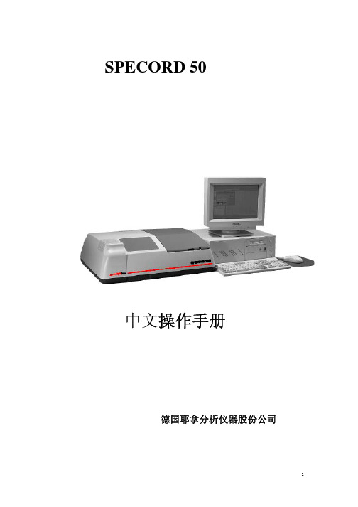
SPECORD 50中文操作手册德国耶拿分析仪器股份公司SPECORD 50 简单操作规程一、开机1.打开Specord50主机电源2.打开电脑电源3.双击WinAspect软件图标,进入操作软件。
4. WinAspect 软件工作区界面如下:5.点击Measurement测量菜单下的初始化命令Initialize Device,进入仪器和软件的联机过程,初始化后,可进行样品测量的设定与执行。
二、关机1、点击Exit或按钮,退出WinAspect软件。
2、关掉电脑电源。
3、关掉Specord50主机电源。
三、WinAspect 软件的各功能键介绍:1、点击文件File按钮,出现下拉菜单:2、点击测量Measurement按钮,出现下拉菜单:3、击定量测量Quant按钮,出现下拉菜单:4、点击其他Extra按钮,出现下拉菜单:5、点击帮助Help四、波长扫描1、在工作区内,点击测量Measurement菜单下的设定参数Set Parameter命令,进入参数界面:在设定Setings界面下有:测量重复次数 Cycle Mode(不重复、手动、自动、时间控制),显示模式Display(透过率、吸光度、能量),空白校正模式Correction(不校正、标准校正、参比校正、特殊校正)。
用户可以根据以上默认参数设定。
2、点击仪器Device 按钮,进入仪器设定界面:在仪器Device界面下有:在线波长显示值Online display on wavelength串口设定 COM-Port灯源切换点Lamp Change at用户可以根据以上默认参数设定。
3、点击测量模式Mode 按钮,进入模式设定界面:在测量模式Mode界面下有:测量模式Meas. mode:扫描模式Scan Mode波长范围 Range:可根据需要设定,如200-300nm波长间距Delta lambda扫描速度Speed积分时间 Integration time4、点击附件Accessories 按钮,进入附件设定界面:如果有配附件,就选择相对应的附件,否则选择NONE。
AEMC 电压测试仪数据手册说明书

• Storage of 80,000 measurements
• Includes DataView® software for data storage, real-time display, analysis and report generation
• Optically-isolated USB communication for transfer onto PC and report generation with DataView® software
Real-time display of measurement results.
Clear and straight forward set up of parameters.
Clear and easy setup from one dialog box for Model 5060.
One button operation starts test and graphs results
Test voltage selection
Four tabbed dialog boxes allow for clear and easy setup of all functions of the Model 5070, including setup for variable voltage and alarm set points, as well as step voltage tests and temperature compensation.
• Fixed or programmable test voltage from 40V to 10kV/15kV
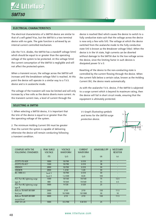
SMT50资料
°C °C
Tstg
Type
Marking
IRM @ VRM MAX (µA) 2 2 2 2 2 2 2 2 2 2 (V) 56 60 90 180 117 162 180 198 216 243
IRM @ VR MAX (µA) 50 50 50 50 50 50 50 50 50 50 (V) 62 68 100 12C/W °C/W
ABSOLUTE MAXIMUM RATINGS (Tamb 25°C)
SYMBOL P IPP PARAMETER Power dissipation Peak pulse current Tlead 10/1000µS 8/20µS I TSM dV/dt Tstg Tj TL Non repetitive surge peak on-state current Critical rate of rise of off-state voltage Storage temperature range Maximum junction temperature Maximum lead temperature for soldering during 10s tp + 20ms VRM VALUE 5 50 100 30 5 -55 to +150 150 260 UNIT W A A A KV/µS
THERMAL RESISTANCE
SYMBOL RTH (J-I) RTH (J-I) PARAMETER Junction to leads Junction to ambient on printed circuit (with standard footprint dimensions) VALUE 20 100 UNIT
EMC测试验证规范手册

EMC测试验证规范EMC测试验证规范由于新环境的冲击以及高科技时代技术发展的趋势,需加强全面性可靠度工程技术的整合与应用,才能提高产品的竞争力。
因此应引用系统工程理念建立整体产品开发程序,已达成满足客户的需求及有效降低产品开发周期与成本的终极目标。
由可靠度发展的时间角度可区分如下:一.概念阶段由于开发时程的紧缩及可靠度需求的日益重视,所以在概念设计时,就需导入整体可靠度工程,已达到避免重复试误及即早将可靠度design in产品的目的。
二.设计阶段由于开发时程的紧缩及可靠度需求的日益重视,所以在设计阶段时,研发工程师需依各相关单位的设计标准作设计上的考虑,以达到产品功能、质量及制造性皆能兼顾的目标。
三.鉴定阶段开发阶段已完成欲进入生产阶段时,为了确保设计与制程已稳定,此衔接工作需紧密结合,以确保design In的质量。
四.生产阶段当开发阶段完成已进入生产阶段时,为确保生产时程、生产质量获得控制,客诉问题能快速处理、追踪,甚至于整体项目成本和利润的分析,相关的可靠度工程亦需配合导入。
貳.测试设备及仪器一.冷热冲击机●Model:ES-203L●Temperature range:-65℃ to 100℃●Humidity range:+60%RH to +200%RH●Temperature / Humidity Distribution:±0.4℃/ ±3% R.H.●Temp. restoration time: Within 12 min●Withstand load:Max. 50 kg恒温恒湿机●Model:EC-23MHHP●Temperature range:-40℃ ~ 150℃●Humidity range:20% ~ 98% R.H.●Temperature/Humidity Distribution: ±0.4℃/ ±3% R.H.●Temp. rise time:Within 60 min for -40 to 150℃●Temp. drop time:Within 60 min for +20 to -40℃二.线材摇摆试验机●Model:JIA-615●Flexing Angles:45°, 60°, 90°, 180° (Adjustable)●Flexing Speed:10 ~ 60 CPM (Adjustable)●Auto-Counter:6 set & all independent●Grips:6 set●Load:100g, 200g, 300g, 500g三.落下试验机●Model:HT-4180●Drop Height:400 mm ~ 1500 mm●Withstand Load:60Kg max.●Drop Control:electro-megnetic Control四.ESD静态放电测试仪●Model:NSG-435●ACCORDING TO:IEC 801-2IEC 1000-4-2五.雷击测试仪●Model:LSS-6030●Output surge waveform1)Combination wave 1.2/50 μs,8/20μs2)10/700μs Telecom waveform3)0.5μs/100kHz Ring waveform●Maximum output voltage (current)1)500V~6kV±10%(1.2/50μs voltage surge)250A~3000A±10%(8/20μs voltage surge)2)500V~6kV±10%(10/700μs voltage surge)3)500V~6kV±10%(Ring wave)●According to:IEC61000-4-5六.振动测试仪●Model:G-0170L●Sinusoidal force output:700kgf●Random force output:490kgf●Frequency range:5-3000 Hz●Max. Acceleration:87G●Max. Velocity:110cm/sec●Max. Displacement:51mm p-p七.安规综合分析测试仪八.拉力机九.温度纪录器參.产品验证一.产品验证流程●测试目的:实验中心之测试目的可分为”新产品验证测试”及”量产证测试”,其样本数依客户、产品类别、测试目的等进行抽样。
Reliant EMC LLC 环境测试设备技术数据说明书
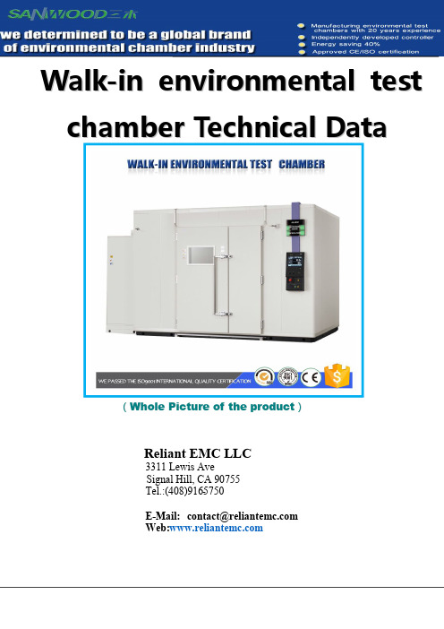
Walk-in environmental test chamber Technical Data(Whole Picture of the product)Reliant EMC LLC3311 Lewis AveSigna l Hill, CA90755Tel.:(408)916-5750E-M ail:contact@reliantem Web:w The reason for choosing SANWOOD EquipmentTechnical featuresA.With USB disk recording function,do not need recorder;B.The wide range of temperature and humidity,the standard model can reach60(40)10%RH;Refrigerant servo valve control flow calculation,saving more than30%energy;1、High temperature and high humidity test to prevent condensation of moisture and drip,the technologyranks first in the industry2、Low temperature working state,the heater does not participate in the work,through the PWM technologyto control the refrigerant flow and flow direction,the cooling pipe,cold bypass pipe,heat bypass pipe three to flow regulation,to achieve automatic constant temperature of the studio.This method can reduce the energy consumption by40%;3、Temperature and humidity control of synchronous lifting slope,no drop,no condensation;4、Low noise,only55dB at low temperature testing;5、Refrigeration advantages:6、Traditional equipment low temperature control method:ØConstant operation of refrigeration compressor+Heating PID control Refrigeration and heating temperature offset achieve dynamic balance,waste a lot of energy.Realization of low temperature energy saving operation with new PWM cold control technologyLow temperature working state,the heater does not participate in the work,through the PWM technology to control the refrigerant flow and flow direction,the cooling pipe,cold bypass pipe,heat bypass pipe three to flow regulation,to achieve automatic constant temperature of the studio.This method can reduce the energy consumption by40%.The technology based on the United States Sporlan company customized model PWM control valve:Core Spare Parts:German Schneider Contactor German Schneider Thermal Relay Izumi Japanese Rely high and low voltage protection switchYangming solid state relay Songqi Temperature sensor Dongyuan Circulating Motor Sporlan refrigeration solenoid valveTaiwan Jianli stainless steel wind wheel Taiwan FeiYang Heating Tube Taiwan Zhongli evaporatorMobile castors Rack Oil separatorGermany Bitzer compressor unit South Korean ControllerMain spare parts list:NO Material name Origin/brand Model Quantity life-span1Temperature and humiditycontroller South KoreaSAMWONTEMI-1500115years2AC contactor German Schneider LC1-D25415years 3Thermal Relay German Schneider LRD-08KN210years 4Intermediate Relay Izumi Japanese RU4S-A220510years 5Time Relay Taiwan AnLiang AH3-318years6Over TemperatureProtection South KoreaRAINBOWTS-320S210years7Solid State Relay Taiwan Yangming SSR-40DA68years8Temperature and HumiditySensor Taiwan Songqi PT100215years9Lamp LED12V\18W215years 10Leakage switch South Korea LG DP-40A115years 11Signal Indicator Taiwan Tiande AD16-22D/S31110years 12Flash buzzer Taiwan Tiande AD16-22SM110years 13Switching Power Supply Taiwan Mingwei NES-100-24210years 14No fuse switch German Schneider LC-1P20A210years 15Button Switch Taiwan Tiande AD-22D/S31215years 16Circulating Motor Taiwan Dongyuan DL-220V90W110years 17Circulating Wind Wheel Taiwan Jianli7CL110years18Heating Tube Taiwan Feiyang Customized210years19Pump Motor New Western Hillsjoint ventureDP-125115years20Liquid TemperatureControllerRAINBOW SouthKorea RAINBOWRA-10KG115years21High powerful semienclosed compressor German Bitzer4VES-10215years22Condenser Taiwan Zhongli ZL-2P210years 23Evaporator Taiwan Zhongli ZL-2P215years 24Condenser fan Germany EBM4E-350-Z110years 25Drying filter Danfoss083S215years 26Expansion valve Danfoss TS-2S215years 27Solenoid valve Danfoss DA-083315years 28Refrigerant AmericanLianxing R404A/R23215years 29Refrigeration oil BritishBingxiong RL32H215years 30Oil separator America ALCO S-4004115years 31Vacuum Heating Glass Taiwan DSD Customized115years 32Cooling Fan Taiwan Jianzhun EB-120110years 33Lock America Shangkun SK1-200115years 34Casters Taiwan Zhide Customized415years 35Horizontal Wheel Taiwan Zhide Customized415years1、Library board assembly2、Site complete3、Machine completeAbove the insulation performance of the assembly and the library boardLarge heated windowWithin a5-layer vacuum glassAdditional hot line,automatic defogging defrost Convenient observation of internal testing process) Security doors and internal explosion-proof lighting, pressure regulating deviceSelf-developed 7.0-inch large-screen controller (LCD touch screen,section 1200program,120program memorygroup )Test curve,computer on-line monitoring program,999times program cycle,part of the cycle 4groups of 99times,each0~99H59MComputer InterfaceWaterGeneration SystemOverheating protection,humidifiers overheatingprotection,leakage protection.Main technical parameters:Equipment performanceProduction standard GB/T10586、GB/T10589、GB/T10592、GB/T11158Product Performance Water-cooled,air-cooled machine at no load at room temperature at roomtemperature25℃,or water-cooled water temperature at25℃product name Walk-in environmental test chamberproduct model SM-040-WTInner dimension3800x4150x2500mm(W x D x H)Inner volume40000L(40立方)External dimensions4900x4650x2900mm(W x D x H)temperature range-40℃~60℃Wind speed range 4.0m/s(adjustable)Uniformity of wind speed±20%Temperature Sensor Configuration3temperature sensor accuracy to reach0.01℃Wind Speed Sensor Configuration2wind sensor accuracy reached0.02m/sThe rate of temperature rise-30℃to60℃/have been completed within about60minutes;no-load Temperature drop rate30℃to-30℃/have been completed within about70minutes;no-load Temperature uniformity ofdistribution±2℃Temperature fluctuations of control±0.5℃Temperature overshoot±1℃the room temperature stability≤10min;Machine total weight1300KGMechanical structure design2-1.Structural manner Double door split assembled2-2.Open door size190CM W X240CM H2-3.Within the box material Heat cold stainless steel plate welded full week(SUS#304)2-4.Carton Material A3steel outer box with advanced powder coating2-5.Bottom plate bearing weight Uniform bearing≥400kg/m2-6.Bottom plate Material Using SUS#3043.0mm thick stainless steel skid plate making2-7.Chamber surface temperature During chamber normal operation,the surface may be exposed to the place,part of the metal temperature does not exceed40℃,non-metallic portion does not exceed 50℃2-8.Bottom plate height Test chamber bottom plate height of not more than150mm,to facilitate access tothe test sample2-9.Drainage function Design studio and crew condensate drainage,no water in test chamber,the bottomof the unit watertight;2-10.The main structure design Sheet metal region,circuit region,freeze area waterway area,composed of fourparts.2-11.Anti-condensation dew functions Top box design has a2mm thick stainless steel plate hot wind purge system as an anti-condensation phenomenon2-12.Water tank design Chamber using tap water through water filtration device automatically treated humidification,the treated water conductivity≤10us/cmAll tank chamber,has the lowest water dish drain,the water can be drained and easy to clean2-13.Duct design Use the upper part of the box out of the wind,the lower part of the return air of the structural design,by posing Blinds regulate air flow uniformity to achieve the effect of uniformity2-14.Observation window Install multi-layer hollow rectangular insulated glass windows of a(500×600mm) energy efficient LED lighting on the observation window2-15.Sample rack bearing weight Layer is not more than50kg2-16.Sample holder moves Using SUS#304stainless steel side through production activities moving car2-17.Test hole In the right side of the box,Ф100mm test holes two convenient power test2-18.Insulation Environmental thermal insulation layer flame fire PU+insulated glass wool(insulation thickness10.0cm)2-19.Machine positioning Bottom of the control box to install four high horizontal load sheave and PUwheels to facilitate moving the machine2-20.Door structure Taiwan imported flat embedded rota-table handleHinge:Original Japanese imports to prevent any shaking door,which is made of SUS#304Inside lights with energy-saving LED18W,can be clearly seen inside the four corners of the test items;Twp high tensile resistance,high temperature of silicone foam packing3.Temperature and humidity electric heating cycle system3-1Electric heating cycle system Temperature mining special moisture and heat dissipation design,stainless steel extended axis motor3-2Circulating wind High/low temperature aluminum alloy multivane circulating fan3-3.Electric control mode of heat storagezoneBalanced temperature control of S.S.R P.I.D3-4.Structure microcomputer control Microcomputer control,pre-cooling preheating temperature conversion control,output power from the computer to achieve high accuracy and high efficiency.3-5.Auto-Control The U type fin type high-speed heating electric heaterFully independent system does not affect the frozen and control line Calculation of the heat content of the test object with the heating rate3-6.Humidification system Electronic and position method for micro wetting systemThe wet barrel is made of stainless steel,and with a water level observation windowDouble guarantee device for overheat and overflowWet and desiccant system is completely independent.The water level control adopts the mechanical float ball water raft,anti-electronic type of mistakeFor wet water use automatic replenishment system with filter,the buyer does not need to manually add water.The use of non recycling water system3-7.Desiccant system Independent refrigeration compression systemDew point temperature(ADP)laminar flow contact and desiccant method for evaporating vessel4.Refrigeration system:Using binary-type refrigeration systems,good efficiency,saving energy4-1.Refrigerating apparatus Europe and high efficiency ultra-low temperature refrigeration compressor(air cooling mode)4-2.Heat exchanging devices The design of the SWEP plate cold coal exchange with high efficiencywhich is more traditional..4-3.Heating load regulation Automatic adjustment of cold coal flow by computer,Effectively take the heat load of the sample and the German/Japanese technology simultaneously,Compared with the traditional design,the stability and reproducibility of the control is high and the efficiency of power saving is achieved.4-4.Condenser Using water cooling or air cooling heat dissipation method for the largesystem of the water-collecting pipe type and the tube type4-5.Super efficiency refrigeration controlrefrigerant The refrigerant pipes are welded with the nitrogen pressure and leak test.4-6.Evaporator High efficiency components using slope type evaporator,(AC&R doubleturbulent type aluminum fins)4-7.Standard modular design Compatibility and interoperability of components of high quality stability4-8.Extended Performance The TEMI1500control system can be reserved for isothermal control ofliquid nitrogen valve LN2V&FV control interface.4-9.Extensions Work long hours with low evaporator icing automatic defrost circuit4-10.Special functions Multi-wing circulating fan,forced convection air flow to improve the efficiency of uniform temperature4-11.Special functions The test area is controlled by P.I.D.+S.S.R.microcomputer,which can achieve the control precision.4-12.Refrigerant United States DuPont green refrigerant R404a and R23a4-13.Auxiliary Original Expansion valve(America SPOLAN),Solenoid valve(Italy CASTEL),Filter(America SPORLAN),Pressure controller(Anglo American RANCO),Oil separator(Europe ALCO)etc refrigeration accessories are imported parts5.Control system((TEMI-1500)5-1.Controller combinationA.Controller type TEMI-1500B.Controller origin South Korea SAMWON C.Temperature sensor JIS RTD PT100Ω×2Platinum sensorD.Controller function 5.7inch LCD touch control screen,12000groups of120programming,9999cycles setAnd with a number of PID control,the display screen240x320point wide viewing angle,high contrast with the large LCD display screenE.Controller specification a.Temperature resolution:0.1℃b.Operation mode:Program running,Set operationc.Equipment working time cumulative timerd.PID control modeF T e m p e r a t u r e c o n v e r t e r A microcomputer multifunctional automatic linear compensation and correction, temperature converterG.Screen display a.The control software on screen,the screen directly touch options,including boot settings,Loop,program,display screen,auxiliary setting,system opening program capacity and control functionb.With temperature setting,humidity setting indicatorc.Can display the current state of execution,temperature setting,time setting,the rest time,the remaining number of cyclesd.Function of fault condition and fault elimination method in English,machine can not started with fault unsolvedH.Program capacity and control function a.Can be used by the amount of the program:the maximum999groupsb.Can be repeated orders:each command can be9999timesc.Time setting0~9999Hr59mind.Have an appointment start functione.Key and screen lock(LOCK)functionf.Temperature defrosting time settingg.Attached RS232communication interface and USB interface.h.The temperature,time and the number of cycles can be set.5-2.Controller main functionA.Temperature analytic ability0.01℃B.Temperature control accuracy±0.2℃C.Set time capacity0H1M~9999H59MD.Display language Chinese(Traditional)/EnglishE.Reservation start-up time Reservation time setting function.F.Calculation control Automatic temperature program change control and program link control.G.Screen display Color real time curve display screen(set).Test curves show,no time limit,sampling rate automatically adjustH.Software device for fault record Control of storage/record/analysis when the machine is maintained.I.Controller deviation setting Intelligent digital temperature deviation"return to zero"J.Call back after selection Call back after the blackout"continue""to""stop"setting.K.Control software Automatic adjustment of the cold coal flow,effectively take the heat load of the sample to be measured with the German/Japanese technology Compared with the traditional design,the stability and reproducibility of the control is high and the efficiency of power saving is achieved.L.Upper and lower limit of temperature protection Set up the test procedure,and automatically set the upper and lower limits of the low temperature protection.M.Power failure memory device Can ensure that the stored procedures in the power failure to maintainmemory dataI.Security permission settings Machine operation password permission settingsO.Mode Selection Programmable control mode6.Safety protection system6-1.Leakage/burst protection Leakage protection of electric wave of leakage protection.6-2.Prevention of lightning protection Controller AC power supply is equipped with the arrester ZRN device6-3.Overload protection device AC Power Supply,Three phase power supply.Reverse phase protection and current load over load(over load)High temperature and high temperature protection operation control of high temperature and low temperature protection settingpressor protection Cold media pressure protection and overload protection device.Cold media pressure protection and overload protection device.Compressor internal overheat protectionCompressor high and low voltage protectionCompressor start-up exception protectionCompressor oil pressure difference protection6-5.Protector1group humidification barrel dry protection switch1groups of low water level protection1group of heating system protection switchHeater short circuit protectionTemperature and humidity over temperature balance device6-6.Fault exception protection Fault exception occurs when the control power supply cut off and cause of themalfunction indication and alarm output signal7.Standard configuration:7-1.Test holeψ100mm a hole on the left side of the body attached to a stainless steel manholecovers,silicone plugs17-2Over-temperature protection LED digital microscopic computer controller,preventing the sample temperatureis too high or too low to be destroyed7-3.Fuse Backup fuse7-4.Instruction manual Controller instruction manual Operating instruction manualProduct qualification certificate7-5.Other standard configuration Sample frame four2group of adjustable spacing50mm rack rail4Adjustable horizontal cup wheels6meters5X6square low impedance rubber cable8.Use requirements8-1.Environmental requirements Allowable temperature range0~25℃Performance guarantee range5~25℃Relative humidity:≤85%RHAir pressure:86kPa~106kPa Cooling circulating water:Null Compressed air:Null8-2.Site requirements Smooth ground,well ventilated,non flammable,explosive,corrosive gas and dustNear no strong electromagnetic radiation sourceA floor drain near the equipmentGround bearing capacity:not less than800KG/square metersReserved space for proper maintenance.8-3.Requirements forstorage environment When the equipment works,the temperature of the environment should be kept within0~+4(not frozen).When the equipment works,the temperature of the environment should be kept within0~+4(not frozen).When the equipment works,the temperature of the environment should be kept within0~+4(not frozen).The temperature is below0~+4in the north of the room can not be frozen phenomenon,to ensure that the interior is not frozen,to ensure the normal use of equipment.9、Power supply system:the system power fluctuation is not greater than10%Model Voltage220V±10 Rated currentSMC-225-CC series45A Power 5.5KWQuality Assurance In order to further improve the company's product and company management level,to provide users with high brand,high quality,high efficiency,world-class high-service environmental testing equipment,the company strictly in accordance with IS09001:2008version of the standard of quality assurance system operation.Products manufactured before the quality department need to undergo a quality inspection of nearly a week,to ensure product quality and interests of users。
- 1、下载文档前请自行甄别文档内容的完整性,平台不提供额外的编辑、内容补充、找答案等附加服务。
- 2、"仅部分预览"的文档,不可在线预览部分如存在完整性等问题,可反馈申请退款(可完整预览的文档不适用该条件!)。
- 3、如文档侵犯您的权益,请联系客服反馈,我们会尽快为您处理(人工客服工作时间:9:00-18:30)。
PLA-K1
触点之间主要IN
(另售)
.032 [0.81] .230 [5.84]
.200 [5.08] .103 [2.62]
咨询工厂模内KEY
ETA-K3
密钥将替换一对触点 (另售)
.175 [4.44]
.051 [1.30]
.280
[7.11]
.505
[12.83]
.140 [3.56]行距 EYELET ACCEPTS 3-#26 AWG
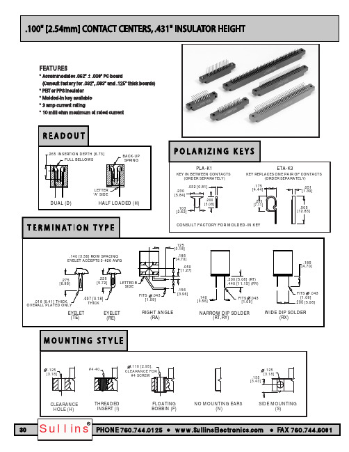
安装形式(对页)
H = .125"[3.18毫米]通孔 N =否安装 S =侧面安装 I=螺纹插入 F =浮动线轴
终端类型(对页)
RA =直角 RE =鸡眼(标准) TE =鸡眼(整体镀专用) RT = .140"[3.56毫米]×0.200"[5.08毫米]浸焊 RY= .140"[3.56毫米]×.440"[11.18 mm]浸焊 RX = 0.200"[5.08毫米]×.185"[4.70毫米]浸焊
73.66 78.74 81.28 91.44 93.98 104.14
111.76 114.30 127.00 129.54 134.62 154.94
B 1 2 3 ... 58 59 60 B A 1 2 3 ... 58 59 60 A
MILLIMETERS
C
D
+_ 0.38 +_ 0.25
间隙
#4螺丝
间隙
孔(H)
螺纹
INSERT (I)
浮动
BOBBIN (F)
否安装耳
(N)
.125 [3.18] .135 [3.43]
侧面安装
(S)
芯片中文手册,看全文,戳
材料(绝缘层/触点)
E = PBT /磷青铜(标准) H = PBT /铍铜 R = PPS /磷青铜 A = PPS /铍铜
2.275 2.575
2.475 2.775
2.575 2.875
2.775 3.075
2.875 3.175
3.075 3.375
3.275 3.575
3.875 4.175
4.275 4.575
4.575 4.875
4.675 4.975
5.175 5.475
.156 [3.96]
.140 [3.56]
.200 [5.08] (RT) .440 [11.15] (RY)
FITS .043 [1.09]
窄浸焊
(RT,RY)
.185 [4.70]
宽浸焊
(RX)
FITS .043 [1.09]
.200 [5.08]
.125 [3.18]
#4-40
.116 [2.95],
读出后(对面页)
D =双 H =半满负荷
号码与位置
05通60
B
A
参考
支撑架
STYLE
F
0.265插入深度[6.73]
C
.431 [10.95]
D
.025 [0.64]
E
.100 TYP. [2.54]
Dimensionsin [ ] are in millimeters, all othersin inches.
68.58 73.66 76.20 86.36 88.90 99.06
106.68 109.22 121.92 124.46 129.54 149.86
B
+_ 0.20
12.70 15.24 17.78 20.32 22.86
27.94 33.02 35.56 40.64 45.72 48.26
50.80 53.34 58.42 60.96 66.04 68.58
17.15 24.77
19.69 27.31
22.23 29.85
24.77 32.39
27.31 34.93
32.39 40.01
37.47 45.09
40.01 47.63
45.09 52.71
50.17 57.79
52.71 60.33
55.25 62.87
57.79 65.41
62.87 70.49
B
+_ .008
0.500 0.600 0.700 0.800 0.900
1.100 1.300 1.400 1.600 1.800 1.900
2.000 2.100 2.300 2.400 2.600 2.700
2.900 3.100 3.200 3.600 3.700 4.100
4.400 4.500 5.000 5.100 5.300 6.100
65.41 73.03
70.49 78.11
73.03 80.65
78.11 85.73
83.19 90.81
85.73 93.35
95.89 103.51
98.43 106.05
108.59 116.21
116.21 123.83
118.75 126.37
131.45 139.07
133.99 141.61
Ëz对于C 43ðRE ^ h -S13
托板
0.000050"镍 0.000050"镍 0.000050"镍 0.000050"镍
托板
0.000050"镍 0.000050"镍 0.000050"镍
修饰(咨询工厂) 省略为标准
-S13 =卡扩展器.062"[1.58毫米]厚PCB -S93 = .093"2.36 mm]厚PCB
C = PPS /铍镍(咨询工厂) N = PEEK /铍铜(咨询工厂) W = PEEK /铍镍(咨询工厂)
F = PPS / Pfinodal ***(咨询工厂)
咨询工厂其他材料
触点表面涂层
接触面
Z = 0.000010"金 X = 0.000030"金 G = 0.000010"金奖 Y = 0.000030"金奖
INCHES
C
+_ .015
D
+_ .010
0.675 0.975
0.775 1.075
0.875 1.175
0.975 1.275
1.075 1.375
1.275 1.575
1.475 1.775
1.575 1.875
1.775 2.075
1.975 2.275
2.075 2.375
2.175 2.475
.275 [6.98]
.225 [5.72]
字母b SIDE
0.016 [0.41]厚, 总体PLATED ONLY
.007 [0.18] THICK
EYELET (TE)
EYELET (RE)
FITS .043 [1.09]
直角
(RA)
.125 [3.18]
.185 [4.70]
.050 [1.27]
A
+_.008
0.300 0.400 0.500 0.600 0.700
0.900 1.100 1.200 1.400 1.600 1.700
1.800 1.900 2.100 2.200 2.400 2.500
2.700 2.900 3.000 3.400 3.500 3.900
4.200 4.300 4.800 4.900 5.100 5.900
终止
0.000100"天 0.000100"天 0.000005"金奖 0.000005"金奖
接触面
T = 0.000100"天 S = 0.000010"金 M= 0.000030"金奖
总体电镀
0.000100"天 0.000010"金奖 0.000010"金奖
联络中心
C = .100" [2.54 mm]
.245 [6.22]
是指终端类型
PART NUMBER**
EZC04 _ _ _* EZC05 _ _ _ EZC06 _ _ _ EZC07 _ _ _* EZC08 _ _ _ EZC10 _ _ _ EZC12 _ _ _ EZC13 _ _ _ EZC15 _ _ _ EZC17 _ _ _ EZC18 _ _ _ EZC19 _ _ _ EZC20 _ _ _ EZC22 _ _ _ EZC23 _ _ _* EZC25 _ _ _ EZC26 _ _ _ EZC28 _ _ _ EZC30 _ _ _ EZC31 _ _ _ EZC35 _ _ _ EZC36 _ _ _ EZC40 _ _ _ EZC43 _ _ _ EZC44 _ _ _ EZC49 _ _ _ EZC50 _ _ _ EZC52 _ _ _* EZC60 _ _ _
131.45 133.99 146.69 149.23 154.31 174.63
F
+_ 0.13
8.38
10.16
NUMBER OF
CONTACTS 4/8 5/10 6/12 7/14 8/16
10/20 12/24 13/26 15/30 17/34 18/36
19/38 20/40 22/44 23/46 25/50 26/52
28/56 30/60 31/62 35/70 36/72 40/80
43/86 44/88 49/98 50/100 52/104 60/120
5.175 5.275 5.775 5.875 6.075 6.875