RemoDAQ-8570用户手册V2.0
RemoDAQ-8520C模块用户手册V1.1
V1.0 2007.12.20 RemoDAQ-8520C 模块用户手册北京集智达智能科技有限责任公司目录1 概述 (2)2 功能说明 (2)3 端子定义 (2)4 跳线设置 (5)5 接线 (6)1 概述Remo-8520C是RS-232/422串口中继、转换模块。
可通过跳线进行RS-232/422工作方式选择。
2 功能说明z速率:内置“自适应”电路,自动调节波特率,300~115200bpsz串口工作方式:两路串口(COM1、COM2)都支持RS232/RS422方式,可通过跳线选择。
z电源:+10V ~ +30VDCz隔离电压:3000Vz连接器:可插拔端子3 端子定义J1(COM1):RS-232模式:12 RXD03 TXD045 GND06789 +Vs10 GND22RS-4模式:1 RX0+2 RX0-3 TX0+4 TX0-5 GND06789 +Vs10 GNDJ2(COM RS-2模式:2):3212 RXD13 TXD145 GND16 78910RS-4模式:221 RX1+2 RX1-3 TX1+4 TX0-5 GND16789104 跳线设置串口工作方式选择:z COM1(J1):RS-232方式:将跳线JP1、JP3、JP5的1、2脚短接。
RS-422方式:将跳线JP1、JP3、JP5的2、3脚短接。
z COM2(J2):RS-232方式:将跳线JP2、JP4、JP6的1、2脚短接。
RS-422方式:将跳线JP2、JP4、JP6的2、3脚短接。
5 接线RS-422中继方式接线方法:RS-232中继方式接线方法:RS-232、RS-422转换方式接线方法:。
RemoDAQ-8000-9000 Series Utility工具软件用户手册V1.1

V1.1 2008-10-17RemoDAQ-8000-9000 Series Utility用户手册北京集智达智能科技有限责任公司1、RemoDAQ-8000系列模块的软件使用方法 (3)1. 1参数设定 (3)1.2 搜索模块及数据显示: (4)1.3 改变通信协议方法 (6)1.4 改变波特率和校验和 (7)1.5 RTU协议下的模块及数据显示 (7)2、RemoDAQ-8073电量采集模块的软件使用方法 (8)2.1 搜索模块: (8)2.2 数据显示: (9)2.3 改变波特率和校验和 (10)3、RemoDAQ-9000系列采集控制器的软件使用方法 (10)3.1参数设定 (10)3.2搜索模块及数据显示 (11)3.3改变通信协议、波特率及校验和 (14)RemoDAQ-8000-9000 Series Utility软件是北京集智达智能科技有限责任公司开发的RemoDAQ-8000系列模块和RemoDAQ-9000系列采集控制器的配套工具软件。
它可以用来方便地配置和使用模块及采集控制器。
它支持ASCII协议命令集,主要完成模块及采集控制器参数的设定和I/O功能测试;而且它支持MODBUS RTU协议下I/O功能的测试。
在使用MODBUS RTU 协议前,请先用RemoDAQ-8000-9000 Series Utility在ASCII协议下将模块参数改为用户所需要的,然后将通信协议改为MODBUS RTU。
RemoDAQ-8000-9000 Series Utility工具软件主要完成以下功能:模块及采集控制器的参数设定:输入输出信号类型、范围、地址、波特率、更改通信协议;I/O功能测试:可实现AI/AO、DI/DO 计数的测量或输出。
1、RemoDAQ-8000系列模块的软件使用方法1.1参数设定通过RemoDAQ-8520将RemoDAQ-8000模块连接到计算机串口,然后上电。
活化仪电子版说明书

活化仪电子版说明书作者: 日期:RN-XF蓄电池智能活化仪使用说明书陕西瑞能电气有限责任公司15第一部分 仪器使用说明书••… I 第' 一^章 彳概^述 ............1.1产品概述 ............... 1.2主要功能 ............... 1.3技术指标 ...............第二章主要部件及接线说明2.1主要部件 ............... 2.2接口说明及连线 .........第三章操作指南 ..............开机 .................. 电池充放电 ............ 内阻测试 ............... 电池活化 ...............数据操作 ............... 系统设置 .............. 3.1 3.2 3.3 3.4 3.5 3.6 第四章常见问题及解决…•… 第二部分软件使用说明书••…1打开软件 ................. 2功能操作 ................. 电池充电操作 ....... 电池放电操作 ....... 内阻测试操作 ........电池活化操作 ........ 数据处理操作 ........2.1 2.2 2.3 2.4 2.510 12 13 14 14 15 15 16 17 18第一部分仪器使用说明书第一章概述1.1、产品简介RN-XF蓄电池智能活化仪(2V/12V 一体机是陕西瑞能电气有限责任公司专利产品,适用于2V、12V蓄电池,以下简称活化仪),是日常维护中专用于对落后蓄电池处理的便携式产品。
活化仪采用最先进的脉冲活化技术,针对不同落后电池的实际情况,设置多个循环周期对落后电池做多次循环充放电活化,彻底“清洗”极板硫化物质,有效激活电池硫化的活性物质,从而使电池得到活化,容量得到提升。
1.2、产品主要功能及特点1.2.1、主要特点1、活化仪具有单节电池旁路技术,实现单节电池在线活化,方便、实用。
RemoDAQ-8017B用户手册V1.1
RemoDAQ-8017B⽤户⼿册V1.1V1.1 2008.11.4 RemoDAQ-8017B模块⽤户⼿册北京集智达智能科技有限责任公司⽬录1 概述 (2)1.1 端⼦分布 (3)1.2 特性 (4)1.3 结构图 (4)1.4 接线说明 (5)1.5 默认设置 (6)1.6 跳线设置 (6)1.7 校准 (7)1.8 设置列表 (7)2 命令 (9)2.1 %AANNTTCCFF (11)2.2 #AA (12)2.3 #AAN (13)2.4 $AA0Ci (14)2.5 $AA1Ci (15)2.6 $AA2 (16)2.7 $AA5VV (17)2.8 $AA6 (18)2.9 $AAF (19)2.10 $AA7CiRrr (20)2.11 $AA8Ci (21)2.12 $AAXnnnn (22)2.13 $AAY (23)3 应⽤注释 (24)3.1 INIT* 端⼦操作 (24)1 概述RemoDAQ-8000系列是基于RS-485⽹络的数据采集和控制模块。
它们提供了模拟量输⼊、模拟量输出、数字量输⼊/输出、定时器/计数器、交流电量采集、⽆线通讯等功能。
这些模块可以由命令远程控制。
RemoDAQ-8017B是带有Modbus的8通道z3000 VDC隔离z软件校准z24位ADC提供极⾼的精确度z不同通道同时可以设置为不同量程1.1 端⼦分布1.2 特性RemoDAQ-8017B模拟量输⼊通道:8路或6路差分,2路单端输⼊(跳线选择)输⼊类型:mV,V,mA量程范围:±150mV,±500 mV,±1V,±5V,±10V,±20mA,4-20 mA过电压保护:+/-35V采样频率:10次/ S带宽:13.1 Hz 精确度:±0.1%输⼊阻抗: 20M Ohms零点漂移:+/-6µV/℃满量程漂移:+/-25ppm/℃CMR(50/60Hz):92dB 计时器看门狗:有功耗:1.2W/24VDC隔离电压:3000VDC温度:-20℃~70℃湿度:5%~90%,⽆凝露1.3 结构图1.4 接线说明RemoDAQ-8017B:模拟量输⼊通道0到5接线说明RemoDAQ-8017B:6路差分/2路单端模式模拟量输⼊通道6和7接线说明RemoDAQ-8017B:8路差分模式模拟量输⼊通道6和7接线说明1.5 默认设置z地址: 01z波特率:9600bpsz校验和禁⽌,抑制60Hz⼲扰,⼯程量单位格式z6路差分和2路单端模式1.6 跳线设置RemoDAQ-8017B跳线设置:通道输⼊⽅式(JP0~JP7):20mA输⼊设置电压输⼊设置默认差分/单端模式设置(JP9~JP10):6路差分和2路单端8路差分INIT状态设置:1.在6路差分和2路单端模式下,可通过INIT*接GND设为INIT ⽣效模式,断开为正常模式2.在8路差分模式下,也可通过SW1设置模块在INIT⽣效模式,如图所⽰:INIT⽣效模式正常模式1.7 校准类型代码 07 08 09 0A 0B 0C 0D 零输⼊ 4mA0V 0V 0V 0mV 0mV 0mA 量程输⼊ +20mA +10V +5V+1V+500mV+150mV +20mA校准顺序⽰例(类型 08)1.模块通电预热30分钟2.设置类型为083.校准允许4.给定零校准电压5.执⾏零校准命令6.给定满量程校准电压7.执⾏满量程校准命令8.重复4到7步三次1.8 设置列表波特率设定(CC)代码0304 05 0607 08 09 0A 波特率 1200 2400 48009600192003840057600 115200最⼤输出 20mA +10V+5V+1V+500mV+150mV +20mA 数据格式设置(FF)7 6 5 4 3 2 1 0 *1 *20 0 00 *3*1:0=60Hz 抑制; 1=50Hz 抑制*2:校验位:0= 禁⽌,1=允许*3:00 = ⼯程单元格式;01 = 百分⽐格式10 = 16进制格式模拟量输⼊类型和数据格式表类型输⼊量程数据格式+F.S. Zero -F.S 代码⼯程量单位20mA +000.00 4mA07 4~20mA%(FSR)+100.000+000.00 25.0016进制(补码)7FFF 0000 1999⼯程量单位+10.000+00.000 -10.00008 -10~+10V%(FSR)+100.000+000.00 -100.0016进制(补码)7FFF 0000 8000⼯程量单位+5.000+0.000 -5.00009 -5~+5V%(FSR)+100.000+000.00 -100.0016进制(补码)7FFF 0000 8000⼯程量单位+1.000+0.000 -1.0000A -1~+1V%(FSR)+100.000+000.00 -100.0016进制(补码)7FFF 0000 8000⼯程量单位+500.000+000.000 -500.0000B -500~+500mV%(FSR)+100.000+000.00 -100.0016进制(补码)7FFF 0000 8000⼯程量单位+150.000+000.000 -150.0000C -150~+150mV%(FSR)+100.000+000.00 -100.0016进制(补码)7FFF 0000 80000D -20~+20mA%(FSR)+100.000+000.00 -100.0016进制(补码)7FFF 0000 8000 2 命令命令格式:(Leading)(Address)(Command)(CHK)(cr) 响应格式:(Leading)(Address)(Data)(CHK)(cr) [CHK] 2字符校验[cr] 命令结束符,字符返回(0x0D)计算校验和:1.计算命令或回答字符串中除cr以外所有字符ASCII值的和。
富利安自动电源切换器说明书

F50-ATS50amp 125/250V Automatic Transfer Switch Furrions ATS is used to safely switch automatically between mutiple power sources.N O I R R U F C MO Furrion’s 50amp Automatic Transfer Switch with built in safe switch interlock system is used to automatically switch between two separate 12/2 volt AC power sources, these power sources can be from a Generator, shore power cord or inverter.The function of the Furrion Automatic Transfer Switch is to provide a safe and smooth switch over from an inverter or shore power cord automatically when a generator is interlock between contactors to ensure both contactors cannot be closed in parallel which could otherwise create an over voltage situation on the output line.The electrical contacts in the transfer switch are normally in the open position, once AC voltage is applied to input 1 this will automatically close the contacts in contactor 1 and feeds the output line from the shore power cord or inverter.Once AC power from the Generator is sensed by the transfer switch at Input 2 terminals, this will start a timer and automatically switch over to generator power supply after abefore electrical load is applied.PLEASE READ ALL SAFETY INSTRUCTIONS BEFORE INSTALLING THIS TRANSFER SWITCH!WHEN PROTECTED BY A MOLDED CASE CIRCUIT BREAKER RATED TO 50AMPS OR LESS, THIS LINE/GENERATOR SWITCH IS RATED TO 5000 SYMMETRICAL AMPS.BEFORE PREFORMING MAINTENANCE OR INSTALLATION PLEASE ENSURE TO ISOLATE ALL POWER SOURCES!cannot mistakenly be plugged in.connections before beginning installation or maintenance.Label all electrical parts with a warning tag to show work is in progress beforebeginning work.!!!!!Furrion warranties this transfer switch in the Continental Untied States of America and Canada from defects in materials or workmanship under normal use for 1 year from date of purchase.M INSTALLING YOUR F50-ATS:This is the standard installation used between a shore power cord and generator.distribution panelsWarning:The Furrion F50-ATS is not suitable to be used with Medical life support equipment.R R U F MFor mounting and installing the transfer switch you will require:3 x 1” Cable strain relief’s4 x Self tapping screws with a minimum length of 30mm to mount ATS box 1 x Torque screw driver with square head #21 x Philips screw driver #2MOUNTING YOUR F50-ATS:The Furrion ATS is best mounted indoors or in a location sheltered from outdoor elements. The selected area must be free from the possibility of contaminates and away from water Do not mount the ATS in a engine compartment.The ATS mounting location must be accessible after installation is complete to facilitate future servicing, if possible mount the ATS close to power cord Point of entry or generator output.Typical examples of mounting locations are:Inside seat or bed compartments Above or behind cabinets’To mount the ATS box the 4 screw lugs on the outside of the box can be used to secure, the ATS box also has an alternative 4 screw holes inside the box which can also be used. Punch out 3 of the large diameter cable strain holes on the side of the box in thedirections which the cables will be fed from using a blunt object. Ensure to remove all plastic pieces of the punch out cable strain holes by rotating the ATS box upside down.Hold the transfer switch to the desired position and using 4 self-tapping screws securethe transfer switch box. Ensure the switch is securely mounted so it cannot move or vibrate.Once the ATS is securely mounted then screw in the 3 cable strains into the punch out holess e..N O I R R U F C MOWIRING YOUR F50-ATS:50amp 125/2VAC WiringGround = Bare copper wire or green Neutral = White Live/Hot L1 = Black Live/Hot L2 = Red50amp 12VAC WiringGround = Bare copper wire or green Neutral = White Live/Hot = BlackUsing the quick reference wiring guide on the lid of the ATS box, arrange the wires to be fed into the ATS for connection at the corresponding terminals. Generator in Shore Power in Line/feed outEnsure to feed the wires through the cable strains when they enter to ATS box.Shore power and generator cables should be fed into the ATS from the side marked on the box sticker.The line out wires will enter the ATS from the opposite side.See below diagram for wiring layout.Strip 4” of outer jacket from each of the incoming cables.Strip ½” of jacket from each of the wire conductors.Connect the colored wires to the ATS terminals using the diagram aboveUsing your #2 (Robertson’s) square head torque Screwdriver, tighten the terminal screws to 20in-lb minimum and 25in-lb maximumConnect the chassis grounding 8AWG wire to the grounding terminal block on the inside of the transfer switch box. Use the 3/8” through hole to feed the wire through from the outside of the box directly to the terminal block.Using your #2 Square Head Torque Screwdriver, tighten the grounding block terminal screws to 20in-lb minimum and 25in-lb maximum..N O I R R U F C MO.N O I R R U F C MO PLEASE READ THE FOLLOWING SAFETY INSTRUCTIONS...Follow the below steps to test the function of the F50-ATS.BEFORE TESTING :harmful for the transfer switch to switch over power sources while under load.Shut down all power sources to the RVLabel power sources clearly that testing is in progress.If accessible, remove the lid of the ATS to visually check function.ATS FUNCTION TESTING:1. Plug in the shore power cable and turn on the dockside shore power breaker, as soon as the shore side breaker is turned on you will hear a clunk noise immediately as the shore power contactor engages inside the ATS, power is then supplied to the RV from the ATS line out feed.clunk as the Shore power contactor disconnects (keep the shore power cord connected with no power for further testing).3.Start the Generator in the RV and wait for it to run up to speed, as soon as power is fed to the ATS from the generator the green LED indicator light on the internal ATS PCB will illuminate, the ATS has a 20-30 second time delay before engaging the internal contactor to allow for the generator to warm up. After 20-30 seconds you will hear a clunk noise as the generator contactor engages inside the ATS, power from the generator is now supplied to the RV from the ATS line out feed.4. Shut down the generatorATS SWITCHING TESTING:To test the switching function after both function tests have passed:1. Turn on the shore cord shore side breaker to engage the shower power contactor, power is now being supplied to the RV by the shore power.2.Start the generator and wait for it to warm up, after 20-30 seconds you will hear a clunk as the unit automatically switches over power sources from shore power to generator.line out, the power supply should not be interrupted by doing this.4.Turn on the shore power shore side breaker again which will engage the shore powerwill then disengage the generator contactor and automatically switch to running on shore power feed.sTROUBLESHOOTING YOUR F50-ATS:COMMON PROBLEMS:Transfer switch will not switch over from Shore Power to Generator feed.Possible cause: Bad PCB.How to check: Open the transfer Switch lid so the PCB in visible, do not put your hands or touch anything parts inside the box.Turn on the generator so electric is being fed to the ATS, using a multi meter check for correct voltage at the incoming generator wiring terminals.If the correct power is being fed to the ATS from the Generator the ATS PCB’s the green LED illuminated. After 30 seconds if the contactor does not closeIf the PCB’s green LED is not illuminated while generator voltage is present indicates the PCB has been damaged and will need replaced.ContactyournearestFurrionDealer,*******************************POSSIBLE CAUSES FOR F50-ATS PROBLEMS :INGRESS OF FOREIGN OBJECTS INSIDE ENCLOSURE:Reasons:matter to enter the case.Unsuitable mounting position can cause condensation, moisture or dirt to enter the enclosure,Potential Damage: Contactor does not function properly, burned out coils, Metal particles FLUCTUATING POWER OR POWER SPIKES:Reasons:Lighting strikes,Unbalance load at park, Park Black outsUtility service at park is undersized or located next to an industrial environment.Potential Damage: burnt out contactor coils, PCB damage, pitted contacts, further damage to the RV.LOW VOL TAGE POWER SUPPL Y: Reasons:Bad or corroded electrical connection,Extension cord length too longOperating too much load for power available.Potential Damage: Pitted contacts, burnt out contactor coils, further damage to the RV.GENERATOR FEED :Reasons:Generator requires maintenance,Generator Governors or throttle problems Generator Auto Start/Stop failure.Potential Damage: Burnt out contactor coils, PCB damage, pitted contacts, further damage to the RV..N O I R R U F C MOThere are 2 options for mounting the Furrion F50-ATS:Internal holes: 160 x 130mm (6 / x 5 / )51618Option One: Using the external lugs which are located on the outside of the box. Mounting dimensions for the external lugs are:Outer Lugs : 189 x 220mm (7 / x 8 / )1116716Option Two: Using the 4 x internal holes which are located on theinside of the box. Mounting dimensions for the internal holes are:6188。
朗姆2.0电琴系统用户指南说明书
Stereo Triggered Sampler - FirmwaresHow do I know what version I have?Using a computer:Put your microSD card into your computer. Open up the __Sample List__.html file. At the top it will say "Firmware version XXX".Without a computer:1) Go into System Mode (hold both Reverse, both Play, REC and REC Bank buttons down for a few seconds).2) Press and hold the Edit button. Look at the colors of Reverse buttons:Left Reverse = White, Right Reverse = Green ==> 1.5.x (latest version)Left Reverse = White, Right Reverse = Yellow ==> 1.4Left Reverse = White, Right Reverse = Orange ==> 1.3Left Reverse = White, Right Reverse = Red ==> 1.2Left Reverse = Orange, Right Reverse = Orange ==> 1.0 or 1.1 (see note below)3) If the Reverse buttons stay Orange, then you have v1.0 or 1.1. To tell the difference between v1.0 and v1.1, press and hold just the left Reverse button in System Mode. If both Reverse buttons turn White, then you have v1.1. If they remain Orange, you have v1.0.Change log:v1.5.2bReleased: October 14, 2022Download:Firmware v1.5.2bImprovements:Bug Fixes:Start Pos would not go back to 0: With longer sample files, adjusting Start Pos up and then back to 0 would sometimes set the start position such that the first few milliseconds of audio were truncated. Fixed.Clicking when re-triggering a sample with long Fade settings: With longer Fade Up/Down Envelope times, re-triggering an already playing sample would prioritize low latency over the fade-down envelope, causing a click. In v1.5.2b the fade-down envelope is accelerated, adding a little bit of latency when re-triggering but removing the click. Setting the Fade Up/Down envelope time to fast removes the latency and clicking.Looping broken for very short samples when Perc Env is off: When Percussive Envelope was turned off, setting the sample length to be very short could make it not loop. Bug introduced in 1.5.2. Fixed.v1.5.2Released: October 8, 2022Improvements:Smaller firmware update files: The size of the firmware file has been reduced, making the firmware update .wav file smaller by about 57% (from 5:55 to 3:22).Bug Fixes:Long Fade In/Out Envelope times caused clicking in audio under certain circumstances: When the Fade In/Out Envelope Time was set longer than the Trigger Delay Time, firing a play trigger into a channel that's already playing audio would cause the audio to re-start before the fade out had completed, causinga pop or click in the audio. Another circumstance was if the Fade In/Out Envelope Time or PercussiveEnvelope Time was set longer than time between Start Pos and the actual start of sample data, playing a sample in reverse would result in extra silence or glitchy audio. Bug appeared in v1.5, fixed in v1.5.2.Recording Sample Rate not presevered across reboots: The Recording Sample Rate can be set in System Mode up to 96kHz. However, the next time the STS started up, the rate would be set back to44.1kHz, yet the System Mode lights would indicate it was still in 96kHz. One symptom was that sampleswould play back at the wrong pitch. Bug fixed in v1.5.2.v1.5.1bReleased: June 28, 2022New Features:Force Reload SD Card: Hold down four buttons: Bank 1, Bank 2, Rec Bank and Rec, for about 2seconds. Release the buttons when the startup sequence of lights displays.Bug Fix:Unrelated sample file played in certain circumstances: When Start Pos was high, within 0.5s of the end of the file, and Length was just under 50% (Percussive mode) but high enough such that a percussive burst longer than 0.5s was to be played, then the STS would overrun the sample data and play unrelated data (usually a previously played sample). Bug appeared in v1.5, fixed in v1.5.1b.(Note: v1.5.1a was not released)v1.5Released: June 6, 2022Download:Firmware v1.5New Features:Looping Fade Time: The STS can make a longer crossfade between the end and start of a loop(adjustable from 0.36ms to 250ms). This results in a smoother, click-free loop.LED Color Adjustment: You can now adjust the red, green, and blue amounts of each button, letting you match the colors between buttons. All new units ship pre-calibrated.Maximum Recording Rate: You can now record up to 96kHz.Auto Increment Sample Slot on Record: You can enable a mode that moves to the next sample slot each time you finish a recording that was started with the Rec Trigger jack.REC button flashes when you change sample slots: The REC button flashes red or white when you turn the REC Sample knob to indicate if the slot is full or empty.Bug Fix:PLAY button stayed dim red after a recording into an active slot: Fixed. The PLAY button nowindicates the selected sample slot is full immediately after recording into a previously empty slot.STS hangs on boot in some circumstances: Fixed. An issue where the STS could hang on boot while searching for missing sample files is now fixed.v1.4gReleased: August 4, 2020Download:Firmware v1.4gBug Fix:Sequencing Start Pos Glitch Fixed: Using a sequenced CV into Start Pos with gates/triggers into Play Trig would sometimes play the wrong start position if Length was < 50% and triggers were fired fast enough. Fixed.Intermediate versions:(1.4f released June 17, 2020. Improved performance of start-up sequence, and more types of "extended" wav file formats supported)v1.4eReleased: October 20, 2017Download: (not available, please use v1.4g)New Features:Reduced latency by pre-loading each sample file in a bank the first time each sample is played.Latency from trigger until audio output as low as 0.7ms (with Trigger Delay turned to 0, see below)The first time a sample is played after the bank is changed, latency is typically 5ms (may be moredepending on wav file's sampling rate and bit depth). Subsequent times the sample is triggered thelatency is 0.7msVariable "Trigger Delay": Edit + REC Sample knobCompensates for slew/lag when using a CV Sequencer with the Play Trig jack and the either theSample CV or 1V/oct jackThis feature also allows for latency reduction compared to prior firmware versions, which had a built-in delay of about 14msAfter receiving a trigger on the Play jack, the STS will wait the specified delay period before reading the 1V/oct and Sample CV jacks.To use: Press Edit and turn Rec Sample knob. The knob's numbers (1-10) correspond to a delayamount:PCB v1.0a: ranges from 0ms delay (knob at 1) to 14.3ms delay (knob at 10)PCB v1.1: ranges from 0ms delay (knob at 1) to 1.9ms delay (knob at 8), and extra-long delays of 4.1ms (knob at 9) and 8.2ms (knob at 10)Note: If upgrading to v1.4 causes your sequencer and STS to not play well together, set the Trigger Delay to "8" or higherMonitoring on/off per channel: Left and right channels can monitor the inputs separately.Pressing PLAY on one channel while monitoring is on will turn monitoring off for just that channel.Only works in Mono mode.Monitor LED blinks to indicate split monitoring.Typical use would be to patch Right OUT -> Left IN, then Left OUT -> mixer. Then record the right channel's playback.Start-up banks: Can set the default bank to be loaded at start-up.Hold down Edit + Bank 1 + Bank 2 + left PLAY (Save) for 1 second. Current bank selection will be saved as the default after power on.Envelopes can be turned off: Both percussive envelope and longer playback fade in/out envelopeTwo types of envelopes can be turned on or off:Percussive Envelopes: this is the decay-only envelope applied to playback when Length < 50% (actually an attack-only envelope when Reverse is on)Fade In/Out envelope: this is a very short envelope applied to any sample that's played withLength > 50%. It reduces clicks when starting, stopping, or looping playback.In System Mode, left channel Reverse button sets the envelope settings:Orange: Both envelopes enabled (default)Red: Percussive envelope disabledYellow: Fade In/Out envelopes disabledOff: Both envelopes disabledTurning off all envelopes is recommended when playing CV sample files (wav files with clocks/gates, sequencer CV, or slow LFO waveshapes, etc).Turning off Percussive Envelopes is interesting when doing "Granular" patches (see User Manual for example patches)Can toggle Percussive Envelope mode by turning left side Length to 0, and holding left side Reverse for 2 seconds: Reverse button will flash/flickerCan toggle Fade In/Out Envelope mode by turning left side Length to 100%, and holding left side Reverse for 2 seconds: Reverse button will flash/flickerAfter exiting System Mode, right side Length was set to 0, until the knob was moved. Fixed.Intermediate versions: (1.4beta-1 released October 13, 2017) (1.4beta-2 released October 17, 2017: changed Length behavior) (1.4c fixed sticky right length knob when exiting system mode) (1.4d fixed bugs that appeared in v1.4beta2) (1.4e fixed bugs that appeared in v1.3) (1.4f more filtering on 1V/oct jacks, and quantized mode plays better with tracking comp setting)v1.3Released: (beta released Sept 26, 2017)Download:Firmware v1.3 WAV fileNew Features:Drag-and-dropping WAV files to SD card works better:Adding WAV files to an existing folder now adds the files to the bank if there are empty slots.If there are no empty slots, the files can be added using Edit + Next File.On boot, the STS will try to fill empty slots in banks by searching in the bank's folder:If the bank contains files from multiple folders, the lowest-numbered sample file's folder is used.Adjust 1V/OCT jack offsetHold down Bank 1 + Bank 2 + Edit while tapping either REC or REC Bank button.REC shifts downwards, REC Bank shifts upwards.Settings are saved in memory (save using Edit + Save after making necessary adjustments).If there is a difference in pitch between the audio being monitored and playback, or a difference inplayback pitch between channels, then this may need to be adjusted. All units are calibrated in thefactory, but variations in power supplies and grounding configurations of cases may cause DC offsetto appear in a user's system.Fixes:Creating a folder with an exact color name in all lowercase added the folder twice. Fixed.Edit+Next File while in an empty slot now searches in the folder of the first filled slot.Released: (released Sept 8, 2017)Download:Firmware v1.2 WAV fileNew Features:Quantize 1V/oct jack added to System Mode. Each channel can be on/off seperately. Quantization is to semitones (12 notes per octave).In System Mode, tap Bank button for either channel to toggle state.Blue = On (jack is quantized to semitones)Orange = Off (jack is not quantized)Only effects 1V/oct jack, not the Pitch knobSetting is saved in settings file on microSD cardReset tracking compensaion to 1.0000Holding Edit+Rec+RecBankUpdating from v1.0 or v1.1 to v1.2 or later automatically sets tracking to 1.0000 the first time it isloaded (this is necessary because tracking is calculated differently in v1.2 and later)Auto Stop When Sample Changes: "Always keep playing" mode added. There are now three Auto Stop modes. The modes determine what happens when the sample is changed while a sample is being played.Red = Always Stop: The sample instantly stops playing. If looping is on, the new sample startsplaying immediately.Blue = Change When Looping: The sample keeps playing normally -- unless it's looping, in whichcase it stops immediately and the new sample starts.Green = Always Keep Playing: The sample keeps playing normally. If it's looping then the newsample begins when the previous sample reaches the end.Fixes:1V/octave tracking is tighter, +/-0.4 cents over C0-C3Changes:Faster entry into System Mode (2 seconds, instead of 4)Pitch knob's plateau around the center detent is larger, and gradually slopes away from center to make it easier to tune to other sourcesReleased: August 28, 2017Download:Firmware v1.1 WAV fileChanges:On boot, color of lights while index file is loading shows minor version numberIn System Mode, holding down Reverse displays firmware version on Reverse buttons (White, White =1.1)Fixes:Tapping Reverse after changing Channel Volume prematurely updated the Start Pos setting. Fixed.Scrub End setting for samples was not loaded after reboot until Edit button was pushed. Fixed.v1.0Released: August 10, 2017Initial ReleaseFeatures for future firmware versions:Allow for internally patching OUTs to INs for self-recordingSupport AIFF filesWrite index file in background, for faster boot time and "Edit+Save" time。
奥瑞那集团产品说明书
OX520消火栓按钮使用说明书V1.01.0 概述1.1 OX520消火栓按钮(以下简称按钮),是人工发送报警信号、启动水泵及显示水泵运行指示的部件。
1.2 该按钮具有控制器自动编址和电子编码器编址两种编址方式、自动检测消火栓按钮两端电压的功能。
与我公司生产的OZH4800型火灾报警控制器配合使用。
自动编址方式参见控制器使用说明书,电子编码器编址方式参见电子编码器使用说明书。
2.0 结构特征及工作原理2.1壳体材料和颜色采用ABS 复合塑胶设计成型,外观红色、安装方便。
2.2工作原理、工作特性该按钮采用MCU 单片机微处器。
SMT 贴片技术和二线制无极性输入方式设计,具有控制器自动编址和电子编码器编址两种编址方式、自动检测按钮两端电压的功能。
2.3 主要部件该消火栓按钮是由按钮开关、电话插孔、线路板,外壳主要部件组成。
3.0 技术特征3.1 工作电压:DC20V ~ 28V3.2 监视电流: ≤250uA报警电流:≤2mA3.3 线制:二总线,无极性3.4 地址设定范围:1~192号3.5 触点容量:DC24V/1A3.6 环境条件:温 度 -10℃~+50℃。
相对湿度 ≤95%(40±2℃)3.7尺寸及重量长:85mm 宽:85mm 高度:38.5mm 重量:约129g4.0 安装4.1 安装基础、条件及要求4.1.2 安装前消火栓按钮应保存在防尘、防潮、防霉的地方。
4.2 消火栓按钮的布线4.2.1 要求用截面积1mm 2以上的铜质双绞线,每米绞合节数为20~30,导线总电阻低于60Ω,总分布电容低于0.2uF 。
在总线负载较重的情况下,宜根据实际最大负载电流计算导线压降,以保证现场单元得到20V 以上的总线电压。
4.2.2 屋顶的穿线管在装入底座后应使用密封膏或密封胶封堵,防止积水进入消火栓按钮。
4.2.3 接线时导线应使用冷压接线端子或做镀锡处理,不可随意缠绕。
避免线头接触不良。
RemoDAQ-8000快速入门及851X,852X用户手册V1.1

V1.1 2008.11.20RemoDAQ-8000快速入门RemoDAQ-8510族模块RemoDAQ-8520族模块用户手册北京集智达智能科技有限责任公司目录I RemoDAQ-8000快速入门 (2)1设备连接 (2)1.1 设备基本需求 (2)1.2 设备连接 (2)2 RemoDAQ-8000工具软件安装及应用 (4)2.1 RemoDAQ-8000工具软件安装 (4)2.2 RemoDAQ-8000工具软件使用 (4)3 修改模块地址 (5)4 修改波特率和校验和 (7)II RemoDAQ-8510 (8)1 概述 (8)1.1 RemoDAQ-8510管脚功能和说明 (8)1.2 RemoDAQ-8510A管脚功能和说明 (9)2 接线 (9)2.1 RemoDAQ-8510与RemoDAQ-8000系列模块连接 (9)2.1 RemoDAQ-8510A与RemoDAQ-8000系列模块连接 (9)III RemoDAQ-8520/R/A/AR (10)1 概述 (10)1.1 RemoDAQ-8520/R管脚功能和说明 (10)1.2 RemoDAQ-8520A/AR管脚功能和说明 (11)2 跳线设置 (11)3 接线 (12)3.1 RemoDAQ-8520/R与8000系列模块连接 (12)3.2 RemoDAQ-8520A/AR模块连接 (12)I RemoDAQ-8000快速入门1设备连接1.1 设备基本需求z装有WIN 98/2000/XP 任一操作系统PC机一台,RemoDAQ-8000光盘一张z RemoDAQ-8520 RS-232/485转换器1个z RemoDAQ-8000系列I/O模块若干(以8018为例) z DB9 电缆(一头针一头孔)1条z24VDC 电源1个1.2 设备连接计算机、模块与电源接线图如图1所示:计算机与RemoDAQ -8520连接:计算机一侧(DB9 孔) RemoDAQ-8520 (DB9 针) PIN2--------------------------------------------PIN2PIN3--------------------------------------------PIN3PIN5--------------------------------------------PIN5 RemoDAQ-8520/RemoDAQ-8018/电源连接:RemoDAQ-8520 RemoDAQ-8018 24VDC电源PIN1(DATA+)----------------------------PIN7(DATA+)PIN2(DATA-)---------------------------- PIN8(DATA-)PIN9(+Vs) --------------- PIN9(+Vs)------------ 24V+PIN10(GND)------------- PIN10(GND)--------- GND24V GND2 RemoDAQ-8000工具软件安装及应用2.1 RemoDAQ-8000工具软件安装在光盘E:\RemoDAQ-8000系列\RemoDAQ-8000_Utility 目录下,双击SETUP进行安装,安装完成后,在桌面上会出现:RemoDAQ-8000_Utility图标。
DSO5000系列数字存储示波器用户手册(Ver0.9)
FT857说明书
FT857说明书FT 857快速菜单一览表菜单a A/B VFO A/B频率交换 A=B 置VFO A/B同频 SPL VFO A/B收发异频菜单b MW 存储信道检查,存储信道等 SKIP 从扫描列表中删除信道 TAG 选择存储信道的显示类型(频率显示/字符显示)菜单c STO 存储当前VFO数据到快速存储区信道 RCL 调出快速存储区信道 PROC 激活语音压缩功能,调整语音压缩等级菜单d RPT 设置中继差频(+/-/单频) REV 激活反频功能 VOX 发射声控设定,调整声控增益等级菜单e TON/ENC 激活哑音功能 DEC 哑音译码方式选择 TDCH 哑音搜索功能菜单f ARTS 自动应答系统使能 SRCH 智能搜索功能 PMS 存储器扫描菜单g SCN 频率扫描 PRI 激活优先扫描 DW 激活双段守候菜单h SCOP 激活周边频谱监视功能 WID 设定频谱监视宽度 STEP 设定频谱监视信道步长菜单i MTR 发射机信号表类型选择,信号表峰值保持功能设定 PWR 发射机信号表类型选择(功率表、自动电平控制表、驻波表、调制度表) DISP 屏幕显示模式切换,显示屏对比度设定菜单j SPOT BK 激活CW插入操作,CW侧音音量调节 KYR 激活机器内置电子键,设定电子键发码速度菜单k TUNE 激活天调、自适应天线模式,初始化天调、自适应天线 DOWN 下调节 UP 上调节菜单l NB 中频白噪声调整 AGC 自动增益控制模式选择 AUTO 自动增益控制模式:自动、慢速、快速菜单m IPO 跳过接收机前置信号放大器直通/UV段无效 ATT 天线衰减(10dB)/UV段无效 NAR 在29兆FM操作模式下选择低检波模式菜单n CFIL 选择2.4kHz中频滤波器 N/A N/A菜单o PLY1 CW预存储文本自动发射 PLY2 CW预存储文本自动发射 PLY3 CW预存储文本自动发射菜单p DNR 激活DSP数字降噪功能 DNF 激活DSP数字陷波滤波器功能 DBF 激活DSP数字带通滤波器功能菜单q MONI 打开静噪,本键可自定义 QSPL 激活快速异频工作功能,本键可自定义ATC 产生一个1750Hz音频信号用以打开欧洲的中继设备,本键可自定义--------------------------------------------------------------------------------No 菜单选项功能01 EXTMENU 扩展菜单开启02 144MHz ARS 144 MHz自动频偏功能开启03 430MHz ARS 430MHz自动频偏功能开启04 AM&FM DIAL AM/FM模式主旋钮开启05 AM MIC GAIN AM模式话筒增益06 AM STEP AM模式频率步进设定07 APO TIME 自动电源关闭时间设定08 ARTS BEEP 自动应答系统告警音设定09 ARTS ID 自动应答系统呼号发送设定10 ARTS IDW 自动应答系统呼号编程11 BEACON TEXT 1 CW字符串存储(自动发射)12 BEACON TIME CW自定义字符串发射间隔13 BEEP TONE 设备操作音音调设定14 BEEP VOL 设备操作音音量设定15 CAR LSB R LSB模式接收微调设定16 CAR LSB T LSB模式发射微调设定17 CAR USB R USB模式接收微调设定18 CAR USB T USB模式发射微调设定19 CAT RATE CAT端口波特率设定20 CAT/LIN/TUN 外接端子类型设定21 CLAR DIAL SET 频率微调旋钮选择22 CW AUTO MODE CW自动模式设定23 CW BFO CW拍频模式设定24 CW DELAY CW发射接收转换延迟时间25 CW KEY REV CW自动键点划翻转设置26 CW PADDLE 使用话筒UP/DWN做自动键27 CW PITCH CW侧音频率设定28 CW QSK 选择PTT松开后转换时间29 CW SIDE TONE CW侧音音量设定30 CW SPEED CW自动键发码速度31 CW TRAINING 摩尔斯码自训练功能32 CW WEIGHT CW点划宽度比例设定33 DCS CODE 数字哑音编码设定34 DCS INV 数字哑音翻转控制模式设定35 DIAL STEP 主旋钮选择精度设定36 DIG DISP 数据传输频率偏移显示设定37 DIG GAIN 数据传输增益设定38 DIG MODE 数据传输方式设定39 DIG SHIFT 数据传输频率偏移设定40 DIG VOX 数据传输声控等级设定41 DISP COLOR 显示屏背光颜色设定42 DISP CONTRAST 显示屏对比度设定43 DISP INTENSITY 显示屏背光亮度设定44 DISP MODE 显示屏背光控制模式设定45 DSP BPF WIDTH CW DSP音频带宽设定46 DSP HPF CUTOFF SSB/AM/FM高通滤波截止点47 DSP LPF CUTOFF SSB/AM/FM低通滤波截止点48 DSP MIC EQ DSP数字话筒均衡器设定49 DSP NR LEVEL DSP数字降噪设定50 EMERGENCY 仅美国版有效51 FM MIC GAIN FM话筒增益设定52 FM STEP FM模式频率步进设定53 HOME=>VFO HOME频道转存设定54 LOCK MODE 设备锁定模式选择55 MEM GROUP 存储器组开启设定56 MEM TAG 存储器标示设定57 MEM/VFO DIAL MODE SELECT旋钮第二功能设定58 MIC SCAN 手麦扫描功能设定59 MIC SEL 话筒接口外接设备选择60 MTR ARX SET 接收模式下强度计类型选择61 MTR ATX SET 发射模式下强度计类型选择62 MTR PEAK HOLD 信号表数据保持功能设定63 NB LEVEL NB 控制强度设定64 OP FILTER 165 PG A 多功能键A编程设定66 PG B 多功能键B编程设定67 PG C 多功能键C编程设定68 PG ACC 远程控制话筒ACC键设定69 PG P1 远程控制话筒P1键设定70 PG P2 远程控制话筒P2键设定71 PKT 1200 1200bps音频输入强度设定72 PKT 9600 9600bps音频输入强度设定73 PKT RATE Packet 波特率设定74 PROC LEVEL SSB/AM语音压缩强度设定75 RF POWER SET 当前模式下射频功率调节76 PRT SHIFT 中转台差频设定77 SCAN MODE 扫描模式选择78 SCAN RESUME 扫描恢复时间设定79 SPLIT TONE 音频起控模式组合设定80 SQL/RF GAIN SQL/RF旋钮功能设定81 SSB MIC GAIN SSB话筒增益设定82 SSB STEP SSB模式频率步进设定83 TONE FREQ 哑音频率选择设置84 TOT TIME 发射超时定时器时间设定85 TUNER/ATAS 天调/自适应天线设定86 TX IF FILTER 发射中频滤波器选择87 VOX DELAY 声控延时时间设定88 VOX GAIN 声控增益设定89 XVTR A FREQ 频率显示A设定90 XVTR B FREQ 频率显示B设定91 XVTR SET XVTR功能开启设定-------------------------------------------------------------------------------- 897和857说明:A.本文是针对实际使用,其中按钮的编号及位置按照原厂说明书第12页图示B.FT897的两个旋钮,MAIN DIAL和MEM/VFO,本文中分别称为“大旋钮”“小旋钮”一.按键和旋钮说明1. A,B,C,功能键,有十七组,5. POWER 键,开机后短暂地按这个按键,可以在正常和“快速调谐”之间切换,“快速调谐”启动时屏幕上有一个跑步的人的图标6. F,短暂的按一下,可以用MEM/VFO CH旋钮(以下称“小旋钮”)改变功能键ABC对应的内容按住不放(长按),可以启动菜单模式10. SQL/RF旋钮,静噪/射频(增益),美国版中这个旋钮此旋钮用于调整射频和中频增益,在80号菜单(SQL/RF GAIN)中可以更改为静噪控制;其它(国家)版本中,这个旋钮缺省为静噪控制。
马尔斯顿原点 5 合成器用户手册说明书

VALVES
2x ECC83 + 1x EL84
SPEAKER
Celestion Eight-15 8”
POWER CONTROL
2 way switchable High and low
TILT CONTROL
Single channel control Adjust between normal and high treble
2. Connect the supplied mains (power) lead into the mains input on the rear panel first (rear panel function 4.1) and then into an electricity outlet.
爱达顿5P系列无人值守UPS产品说明说明书
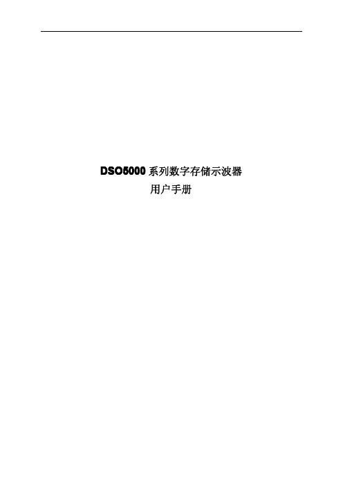
Eaton 5P850GREaton 5P UPS, 1U, 850 VA, 600 W, C14 input, Outputs: (4) C13, 230V, true sine wave, network card optionalGeneral specificationsEaton 5P UPS 5P850GR20 in 1.7 in17.4 in 30.4 lb3 year on electronics, 3 year on batteries with registration CE MarkedRoHS CompliantUL 497ANOMcTUVusUL 1778cULus ListedIEC 62040-2 C1-C2 / EN 55024 /CISPR22 Class B / FCC part 15 Class BProduct Name Catalog NumberProduct Length/Depth Product HeightProduct Width Product WeightWarranty CompliancesCertificationsABM technology (3-stage charging extends battery service life by 50% and provides advance warning for battery replacement)Sine wave850 VA600 W0.7Rack(4) C13Rackmount/wallmountC14<45 dB at 1 meter1View runtime graphEaton Intelligent Power Manager 5-series UPS overview brochureEaton 5P Rackmount UPS brochureEaton 5P850GR 2D drawingEaton 5P UPS visio stencilsEaton 5P UPS 3D drawingsEaton 5P850GR 3D drawingEaton 5P UPS installation and user manualBattery management Output waveformVA ratingWattageOutput power factor Form factorReceptacleStandard factory warrantyMounting MethodInput connectionNoise levelFeed typeRuntime graphSoftware compatibility BrochuresDrawingsManuals and user guides3-YEAR FACTORY WARRANTY w/ REGISTRATION-3 years-Parts, electronics, and batteries coverage-Standard ground shipping -Technical supportUser interfaceLCD graphical displayBattery replacementUser replaceableBattery typeSealed, lead-acidRack size1UVoltage230VTemperature range0° to 35°C (32° to 95°F)CommunicationRS-232 (RJ45) ports; USB port as standard (HID). 6-foot RS-232 and USB cables includedRelative humidity0-90% non-condensingExtended service plansADVANCED DEPOTEXCHANGE-5-YEAR DEPOT REPAIR:5SW5Y-950UC-Expedited parts coveragefor 5 years-Parts, electronics and UPSbatteries coverage-Next business day shipping-Technical support5-YEAR ON-SITE PLAN:WFLN75XX-2509UC- On-site parts and laborcoverage for years 5- Parts, electronics and UPSbatteries coverage- 24x7 on-site laborcoverage, next-dayresponse- Next-day shipping- Technical supportSpecial featuresROO/RPO: Rear terminal block connector for remote on/off and power offColorBlack/silverExtended battery capabilityNone; See Eaton 5PX UPS for extended runtimes optionsOutput voltage range184-256 VacTopologyLine-interactiveBTU RatingOnline: 82, Battery 389Output frequency50/60 HzTypeUPSOutput nominal voltage230V default (200/208/220/230/240V)Input nominal voltage230V default (200/208/220/230/240V)Input power factor1Expansion slotsOne slot; Gigabit Network Card (Network-M2) is optionalInput voltage range160-294 V (adjustable to 150 V-294 V)Input frequency range47-70 Hz (50 Hz system), 56.5-70 Hz (60 Hz system), 40-70 Hz in low-sensitivity modeNominal frequency50-60 HzAltitudeUp to 10,000 ft (3000m) without de-ratingEaton Corporation plc Eaton House30 Pembroke Road Dublin 4, Ireland © 2023 Eaton. All rights reserved. Eaton is a registered trademark.All other trademarks areproperty of their respectiveowners./socialmedia。
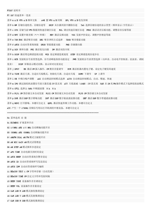
USB 2.0 Extender over CAT5 用户手册说明书
USER MANUALDesigned and Manufactured in the USA 1-888-994-7427OVERVIEWTECHNICAL SPECIFICATIONS_________________________________________________________________ WHAT’S IN THE BOX?________________________________________________________________________ FRONT AND REAR___________________________________________________________________________ INSTALLATION_______________________________________________________________________________ TROUBLESHOOTING_________________________________________________________________________ TECHNICAL SUPPORT________________________________________________________________________ LIMITED WARRANTY STATEMENT____________________________________________________________3 4 4 5 6 6 7Technical SpecificationsWhat’s in the box?FRONT and backUSB2CX-TX Front panelUSB2CX-RX Front panelUSB2CX-TX Back panelUSB2CX-RX Back panelINSTALLATIONUSB2FX-TX Transmitter1. Power off all devices.2. Connect the KM source device (computer) to the USB2CX-TX with a USB cable using the USB-Binput port.3. Install a CAT5 cable into the USB2CX-TX uplink port.4. Connect a power supply to the USB2CX-TX.USB2FX-RX Receiver1. Install the CAT5 cable into the USB2CX-RX uplink port.2. Connect the USB2CX-RX to the desired peripherals using the USB-A output ports.3. Connect a power supply to the USB2CX-RX.4. Power on all devices.TroubleshootingTechnical supportNo Power• Make sure that the power adapter is securely connected to the power connector of the unit.• Check the output voltage of the power supply and make sure that the voltage value is around 12VDC.• Replace the power supply. No Video• Check if all the video cables are connected properly.• Connect the computer directly to the monitor to verify that your monitor and computer are functioning properly.• Restart the computer. Keyboard is not working• Check if the keyboard is properly connected to the unit.• Check if the USB cables connecting the unit and the computers are properly connected. • Try connecting the USB on the computer to a different port.• Make sure that the keyboard works when directly connected to the computer.• Replace the keyboard. Mouse is not working• Check if the mouse is properly connected to the unit.• Try connecting the USB on the computer to a different port.• Make sure that the mouse works when directly connected to the computer. • Replace the mouse.No Audio• Check if all the audio cables are connected properly.• Connect the speakers directly to the computer to verify that the speakers and the computer audio are functioning properly.• Check the audio settings of the computer and verify that the audio output is through the speakers.For product inquiries, warranty questions, or technical questions, please contact *****************.Limited warranty statementA. Extent of limited warrantySmartAVI, Inc. warrants to the end-user customers that the SmartAVI product specified above willbe free from defects in materials and workmanship for the duration of 1 year, which duration begins on the date of purchase by the customer. Customer is responsible for maintaining proof of date of purchase.SmartAVI limited warranty covers only those defects which arise as a result of normal use of the product, and do not apply to any:a. Improper or inadequate maintenance or modificationsb. Operations outside product specificationsc. Mechanical abuse and exposure to severe conditionsIf SmartAVI receives, during applicable warranty period, a notice of defect, SmartAVI will at its discretion replace or repair defective product. If SmartAVI is unable to replace or repair defective product covered by the SmartAVI warranty within reasonable period of time, SmartAVI shall refund the cost of the product.SmartAVI shall have no obligation to repair, replace or refund unit until customer returns defective product to SmartAVI.Any replacement product could be new or like new, provided that it has functionality at least equal to that of the product being replaced.SmartAVI limited warranty is valid in any country where the covered product is distributed by SmartAVI.B. Limitations of warrantyT o the extant allowed by local law, neither SmartAVI nor its third party suppliers make any other warranty or condition of any kind whether expressed or implied with respect to the SmartAVI product, and specifically disclaim implied warranties or conditions of merchantability, satisfactory quality, and fitness for a particular purpose.C. Limitations of liabilityT o the extent allowed by local law the remedies provided in this warranty statement are the customers sole and exclusive remedies.T o the extant allowed by local law, except for the obligations specifically set forth in this warranty statement, in no event will SmartAVI or its third party suppliers be liable for direct, indirect, special, incidental, or consequential damages whether based on contract, tort or any other legal theory and whether advised of the possibility of such damages.D. Local lawT o the extent that this warranty statement is inconsistent with local law, this warranty statement shall be considered modified to be consistent with such law.NOTICEThe information contained in this document is subject to change without notice. SmartAVI makes no warranty of any kind with regard to this material, including but not limited to, implied warranties of merchantability and fitness for particular purpose. SmartAVI will not be liable for errors contained herein or for incidental or consequential damages in connection with the furnishing, performance or use of this material. No part of this document may be photocopied, reproduced, or translated into another language without prior written consent from SmartAVI, Inc.20230223Designed and Manufactured in the USAT el: (888)-994-7427 • (702) 800-00052455 W Cheyenne Ave, Suite 112North Las Vegas, NV 89032。
Marquardt 开关、传感器和控制器产品说明书
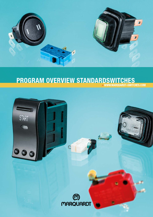
PRogRAM oveRview sTAnDARDswiTchesFurther information underH Content3 ]MARQUARDT45SWITCHES AND SENSORSROCKER SWITCHES \PAGE 6-7ECO SWITCHES\PAGE 14MICRO-SIGNAL SWITCHES\PAGE 14SNAP-ACTION SWITCHES\ PAGE 12-13TACT AND KEY SWITCHES \PAGE 11FOOT SWITCHES\PAGE 10ROTARY SWITCHES\PAGE 10SLIDE SWITCHES\ PAGE 10TOGGLE SWITCHES\PAGE 9PUSHBUTTON SWITCHES\ PAGE 8-9H B eCause C utting-edge t eChnology i s B ased o n k nowledge a nd i ngenuity.\ 4BeCause Cutting-edge teChnology knowledge and ingenuity.H BeCause produCt variety allows tailor-made designsmarquardt switChes and sensors – for a wide range of appliCations 5]Medical and laboratory technologyOffice communication Industrial applications Small household appliancesLarge household appliances Cleaning & drive applications Building technologyHeating-, ventilation- and air conditioning technology Power tools Construction andagricultural machinery Leisure vehiclesAutomobilesFind out more at \ 6Follow the QR Code to find detailed information on the series in the online catalog entry. Corporate Website · Online product catalog SERIES 1900Smallest single-pole rocker switchesto 6 (2) A 250 V ACAppliance cut-out: 19.2 x 6.8 mm23.2 x 6.8 mm30.0 x 6.8 mm SERIES 1800Single and double-polerocker switchesto 12 (4) A 250 V ACAppliance cut-out: 19.2 x 12.9 mm19.2 x 21.9 mm SERIES 1890Single-pole rocker switchesilluminated with LEDto 6 A 24 V DCAppliance cut-out: 19.2 x 12.9 mm SERIES 1881Single-pole round rocker switchesto 12 (4) A 250 V ACAppliance cut-out: Ø 20.3 mmØ 21.2 mm SERIES 1855Miniature double-polerocker switchesto 4 (1) A 250 V ACAppliance cut-out: 19.2 x 12.9 mm SERIES 1858Miniature double-polerocker switchesto 10 (4) A 250 V AC 1E4Appliance cut-out: 19.2 x 12.9 mm SERIES 1941Single-pole rocker switches IP 50to 12 (8) A 250 V AC 1E4Appliance cut-out: 19.2 x 12.9 mm7 ]Follow the QR Code to find detailed information on the series in the online catalog entry. Corporate Website · Online product catalog SERIES 1550Single-pole rocker switchesto 16 (4) A 250 V ACAppliance cut-out: 26.2 x 12.4 mm27.2 x 12.2 mm28.6 x 14.0 mm SERIES 1830Single and double-polerocker switchesto 20 (4) A 250 V ACAppliance cut-out: 30.0 x 11.0 mm30.0 x 22.0 mm SERIES 1930Double-pole rocker switches IP 65to 20 (4) A 250 V ACAppliance cut-out: 30.0 x 22.0 mmSERIES 1656Single-pole rocker switchesto 10 A 250 V ACAppliance cut-out: 28.0 x 13.0 mmSERIES 3230Single and double-polerocker switchesto 10 (5) A 12 and 24 V DCSwitch body: 41.2 x 19.5 mm SERIES 3250Single and double-pole rockerswitches IP 66/IP 68to 20 (10) A 12 and 24 V DC 1E5Switch body: 43.0 x 24.3 mm SERIES 0344Three-pole rocker switchesto 16 (6) A 400 V ACSwitch body: 56.0 x 39.0 mm\ 8Follow the QR Code to find detailed information on the series in the online catalog entry. Corporate Website · Online product catalog SERIES 1680Single and double-polepushbutton switchesto 16 (4) A / 12 (12) A 250 V ACSwitch body: 19.0 x 13.0 mm SERIES 1683Single and double-polepushbutton switchesto 16 A 250 V ACAppliance cut-out: 19.2 x 12.9 mm SERIES 1691Smallest single-polepushbutton switchesfor low voltagesSwitch body: 11.9 x 9.0 mm SERIES 1247Double-pole pushbutton switchesto 7 (7) A 250 V ACSwitch body: 25.0 x 24.0 mmSERIES 5000Round pushbutton switchesfor at least 200 000 mechanical swit-ching cyclesAppliance cut-out: Ø 16.0 mm SERIES 1846Single-pole pushbutton switchesto 2 (1) A 250 V ACAppliance cut-out: 19.2 x 12.9 mmSERIES 1840Single and double-polepushbutton switchesto 6 (4) A 250 V ACAppliance cut-out: Ø 12.0 mm9 ]H toggle switChesFollow the QR Code to find detailed information on the series in the online catalog entry. Corporate Website · Online product catalog SERIES 1660Single and double-polepushbutton switchesto 16 (4) A 250 V ACAppliance cut-out: 30.0 x 22.2 mm SERIES 1670Single and double-polepushbutton switchesto 16 (4) A 250 V ACAppliance cut-out: 30.0 x 22.2 mm SERIES 0350Three-pole toggle switchesto 10 (4) A 400 V ACSwitch body: 30.0 x 28.0 mmSERIES 1810Single and double-pole toggleswitchesto 10 (4) A 250 V ACAppliance cut-out: 19.2 x 12.9 mm19.2 x 21.9 mm SERIES 1820Single and double-pole toggle swit-chesto 6 (4) A 250 V ACAppliance cut-out: Ø 12 mm SERIES 0100Single-pole toggle switchesto 2 A 250 V ACAppliance cut-out: Ø 12 mm\ 10H s lide switChesH foot switChesH rotary switChesFollow the QR Code to find detailed information on the series in the online catalog entry. Corporate Website · Online product catalog SERIES 4021Double and four-pole slide switches to 10 A 125 V or 5 A 250 V AC (as voltage selector switch)Switch body: 26.0 x 16.5 mm26.2 x 30.0 mm SERIES 1206Single-pole slide switches to 8 (8) A 250 V ACSwitch body: 25.3 x 19.4 mmSERIES 1703Powerful rotary switchesto 20 (4) A 400 V ACSwitch body:40.0 x 33.0 mmSERIES 2410Ergonomic foot switchesto 6 (2.5) A 250 V ACSwitch compensator:196.0 x 100.5 mmSERIES 2420IP 65 / 67 protected foot switch to 16 (4) A 250 V AC 25E3Switch compensator:149.0 x 98.6 mm11 ]Ht aCt and key switChesFollow the QR Code to find detailed information on the series in the online catalog entry.Corporate Website · Online product catalog SERIES 3006Tact switchesto 50 mA 28 VSwitch body: 9.85 x 9.85 x 3.95 mmSERIES 6425Key switches to 100 mA 28 VSwitch body: 14.4 x 14.4 x 7.1 mm14.4 x 14.4 x 10.7 mmSERIES 6450Key switches to 100 mA 28 VSwitch body: 14.8 x 10.85 x 13.2 mmSERIES 3000Key switches to 30 mA 28 VSwitch body: 12.4 x 12.4 x 10.6 mm\ 12Follow the QR Code to find detailed information on the series in the online catalog entry.Corporate Website · Online product catalogSERIES 1055Subsubminiature snap-action switches IP 67to 4 A 12 V or 2 A 24 V DCSERIES 1050Subminiature snap-action switches to 10 (1.5) A 250 V ACSERIES 1045Subminiature snap-action switches IP 67to 10 (3) A 250 V AC 1E4Design according to DIN 41635 BSERIES 1080Miniature snap-action switches to 21 (8) A 250 V ACDesign according to DIN 41635 ASERIES 1005Miniature snap-action switches to 21 (8) A 250 V ACDesign according to DIN 41635 ASERIES 1040Rotary shaft snap-action switches to 4 (1) A 250 V ACSERIES 1010Open snap-action switches to 6 (2) A 250 V ACDesign according to DIN 41635 C13 ]Follow the QR Code to find detailed information on the series in the online catalog entry.Corporate Website · Online product catalog SERIES 1019Single-pole snap-action switches to 6 (2) A 250 V ACSERIES 1022Snap-action switches IP 67to 4 A 12 V DCSERIES 1117Snap-action switches to 16 (6) A 400 V ACSwitch body: 30.0 x 30.0 mmSERIES 1115One pole pushbutton switches to 16 (4) A 400 V ACSwitch body: 30.0 x 24.0 mm\ 14Hm iCro-signal switChesHeCo switChesFollow the QR Code to find detailed information on the series in the online catalog entry.Corporate Website · Online product catalog SERIES 1065Micro-signal switches to 100 mA 30 V DCSERIES 1550 ECOSingle-pole rocker switches to 10 (4) A 250 V AC 1E4SERIES 1086 ECOSingle-pole pushbutton switches to 10 (3) A 250 V AC 1E4H notes15 ]。
SEA 857 喇叭 互动系统用户手册说明书

SEA 85760W Loudhailer/IntercomFollowing the tradition of providing quality, high performance communications equipment to fill every mariner’s needs, SEA is proud to announce the SEA 857Loudhailer/Intercom.Offering a full 60 watts of audio power, the SEA 857provides the ability to project voice and fog horn louder and farther in most any condition.Eight internationally accepted warning signals can be selected for automatic operation for a variety of different maritime situations alerting nearby vessels of your presence and status in low visibility conditions.Between warning signals when in the automatic modes,an automatic listen function allows you to hear faint sounds from oncoming boats, navigation buoys, or distant voices.The SEA 857 has the capability to connect up to four intercom stations. This allows 2-way communication between the master station and a specific remote station or all remote stations. The intercom operation remains fully functional even while broadcasting automatic warning signals, providing continuous, ship-wide lines of communication.The custom LCD display keeps you informed of the loudhailer status and the 857’s uncluttered layout and intuitive operation are designed for ease of operation.Both the display and key have adjustable backlighting.An auxiliary audio input allows transmission of music or other external audio signals to the intercom speakers,external horns, or both.The alarm mode allows the hailer to be connected to a switch, that when closed will sound an alarm (yelp, horn,etc.). The SEA 857 will even tell you if a hailing horn or connection is defective.• Full 60 watts of audio power • 8 automatic warning signals• Hail, listen and intercom functions • Alarm function• Console mate to the SEA 157 VHF and SEA 235 (235R) SSB Radiotelephones • Weatherproof construction• Backlit keypad and LCD display • Auxiliary audio input •Alarm FunctionDimensionsin. (mm)SpecificationsAvailable For Signals:Power Board Underway.......UNWY Sail, Fishing, or TowboatUnderway.............................Sail Vessel under tow.................Tow Vessel stopped....................Stop At anchor..............................Anchor Aground ...............................Agnd Manual Yelp.........................Yelp Manual Horn ........................HornOutput Power:Hailer....................................60 Watts @ 10% distortion Intercom...............................4.5 Watts < 10% distortion External Speaker.................4.5 Watts < 10% distortion Internal Speaker...................2.5 Watts < 10% distortion Input:Microphone Impedance.......600 Ohm Auxiliary Impedance.............10 k OhmMicrophone Sensitivity.........-71dB+/-3dB (0dB=1V/µBar)Auxiliary Sensitivity..............0dB +/-3dB (@ 1 kHz)Frequency Response:Hail Mode.............................100Hz-8kHz 3dB Listen Mode .........................100Hz-8kHz 3dB AUX Mode............................100Hz-20kHz 3dB Horn Frequency:500Hz +/-50HzDistortion Factor:Hail Mode.............................<10% (1kHz 30W)Listen Mode .........................<1% (1kHz 2.5W)Signal to Noise:Hail Mode.............................>60dB (@ 1kHz)Listen Mode .........................>60dB (@ 1kHz)AUX Mode............................>60dB (@ 1kHz)Output Impedance:Hail Speaker ........................8 Ohm Intercom Speaker.................8 Ohm External Speaker.................8 OhmPower Supply:Supply Voltage.....................13.6V DCCurrent Consumption...........6A (at 60 Watts)Standby Current...................40 mASpecifications subject to change without notice or obligation.©2000 SEA Inc. Printed in the U.S.A.857(01/2007)7030 - 220thS.W., Mountlake Terrace, Washington 98043; (425) 771-2182; Fax: (425) 771-2650; 。
RemoDAQ-8513模块用户手册说明书

V1.0 2011.8.22RemoDAQ-8513模块用户手册北京集智达智能科技有限责任公司目录1介绍 (3)1.1RemoDAQ-8513管脚功能和说明 (3)1.2引脚定义 (4)1.3内部结构图 (4)1.4跳线说明 (4)2接线 (5)1介绍RemoDAQ-8000系列是基于RS-485网络的数据采集和控制模块。
它们提供了模拟量输入/输出、数字量输入/输出、定时器/计数器、交流电量采集、无线通信等功能。
这些模块可以用命令远程控制。
RemoDAQ-8513是1路RS-485转3路RS-485模块(三端隔离)。
1.1 RemoDAQ-8513管脚功能和说明RemoDAQ-8513:1路RS-485转3路RS-485模块·输入:1个RS-485:Data+,Data·输出:3个RS-485:Data+,Data·传输距离:最长1,200m/9.6K bps;最长400 m/115.2K bps·最多支持设备数:128台设备(无需中继器)·支持自动换向·传输速率:300~115200 bps·ESD保护:有·隔离电压:3000VDC·电源:+10~+30VDC(非稳压)·运行湿度:-25℃~75℃·存储温度:-30℃~75℃·相对湿度:10~90%(非凝露)当DATA0接收时,DATA1~ DATA3同时发送数据,而当DATA1~ DATA3仅其中一路接收到数据时,DATA0发送数据(不支持DATA1~ DATA3三路同时接收或其中两路同时接收)。
1.2引脚定义Termina l No Pinassignmen tTermina l No Pinassignmen t01 DATA0+ 20 DATA1+ 02 DATA0- 19 DATA1- 03 18 04 17 05 16 06 15 DATA2+ 07 14 DATA2- 08 13 09 (R )+Vs 12 DATA3+ 10(B )GND11 DATA3-1.3内部结构图1.4跳线说明一般情况不需要跳线。
RemoDAQ-9000双机热备切换器用户手册

Ver1.0 2008-8-28 RemoDAQ-9000双机热备切换器用户手册北京集智达智能科技有限责任公司1概述.....................................................................................................................................- 2 -1.1 介绍............................................................................................................................- 2 -1.2 特性............................................................................................................................- 2 -1.3 规格............................................................................................................................- 2 -2 启动...................................................................................................................................-3 -2.1了解RemoDAQ-9000双机热备切换器.............................................................- 3 -2.1.1 面板LED功能....................................................................................................- 3 -2.1.2 RemoDAQ-9000双机热备切换器接口图........................................................- 4 -2.2连接硬件....................................................................................................................- 4 -2.2.1导轨安装.............................................................................................................- 4 -2.2.2工作电源连接.....................................................................................................- 5 -2.2.3网络连接.............................................................................................................- 5 -2.2.4串口连接.............................................................................................................- 6 -2.2.5端口定义.............................................................................................................- 6 -1.1 介绍RemoDAQ-9000双机热备切换器是通过RS-232串口对系统中两台RemoDAQ-9821的心跳信号进行采集、判断来实现对条件电源输出端进行切换的设备。
- 1、下载文档前请自行甄别文档内容的完整性,平台不提供额外的编辑、内容补充、找答案等附加服务。
- 2、"仅部分预览"的文档,不可在线预览部分如存在完整性等问题,可反馈申请退款(可完整预览的文档不适用该条件!)。
- 3、如文档侵犯您的权益,请联系客服反馈,我们会尽快为您处理(人工客服工作时间:9:00-18:30)。
V2.0 2008.07.15 RemoDAQ-8570 2端口RS-232/422/485到以太网端口服务器
产品说明书
北京集智达智能科技有限责任公司
1.概述 (3)
1.1 介绍 (3)
1.2 特性 (3)
1.3 规格 (3)
2 启动 (4)
2.1了解RemoDAQ-8570 (4)
2.1.1网络结构 (4)
2.1.2安全通讯 (5)
2.1.3 RemoDAQ-8570 指示灯 (5)
2.2连接硬件 (6)
3 配置工具 (8)
3.1 搜索功能 (8)
3.2 设备描述信息 (9)
3.3 网络设置 (9)
3.4 串口设置 (10)
3.5 网络安全 (11)
1.概述
1.1 介绍
DSLC串口上网服务器RemoDAQ-8570是RS-232/422/485与以太网接口间一款速度快且非常经济的串行设备服务器。
这种单元可立即升级用户集成系统到网络世界的已有设备。
RemoDAQ-8570提供了两个RS-232/422/485串口供用户根据需要分别配置。
RemoDAQ-8570的串口传输速率高达230Kbps,可以满足高速交换的需要。
另外,用户只需使用Windows工具来配置RemoDAQ-8570而不需要其他软件。
功能上透明高效,是专门用于通过互联网进行远程监控的设备。
RemoDAQ-8570连接人机接口(HMI)软件和已有的RS-232/422/485系统结构到以太网。
使用RemoDAQ-8570,用户可以减少电缆线的使用和节约软件扩展费用。
RemoDAQ-8570可以提供一个高性能的RISC CPU和实时操作系统以减少CPU负荷。
这使得RemoDAQ-8570在数据传输过程中更加稳定可靠。
RemoDAQ-8570的另一个优点是它允许用户通过以太网远程下载程序到指定设备。
这减少了现场维护和诊断的需求。
另外,RemoDAQ-8570带有一个基于Windows的配置和端口映射工具。
这个工具可以自动检测本地网络的所有RemoDAQ-8570。
它便于用户调节所有的设置。
端口映射工具可使用户在Windows系统下安装255个端口。
这可帮助用户按照需要管理端口。
1.2 特性
z在Windows系统下可扩展到255个串口
z支持10/100 Base-T以太网标准
z串口支持高达230Kbps的高速传输
z支持LED指示灯:容易诊断
z自动搜索Windows配置工具:容易设置且具有安全保护功能
z端口映射工具:容易管理255个端口及其自我诊断
z容易定位特定的RemoDAQ-8570
z支持实时操作系统
z对RS-485总线和电源有浪涌保护作用
z可以容易地安装到DIN导轨、面板
1.3 规格
z协议:TCP/IP
z网口:IEEE802.3,IEEE802.3u
z接口:
网络:10/100 BASE-T标准
串口:RS-232/422/485
z端口:2个RS-232/422/485端口
z连接器:
网络:RJ-45
串口:RJ-48
z串口传输速度:300bps~230Kbps
z奇偶位:奇,偶,无,空,标记
z数据位:5,6,7,8
z停止位:1,1.5,2
z信号:全调制解调器控制信号(不支持RAS服务)
z诊断LED:
网络:TX/RX,连接,速度(10/100Mbps),电源
串口:TX/RX,状态
z驱动支持:
Windows 95/98/NT/2000/ME/XP 驱动
z电源要求:带浪涌保护,10~30VDC
z功耗:4.5W
z安置:DIN-导轨,面板安装
z工作温度:0~60℃
z贮存温度:-20~80℃
z工作湿度:20~95%(无凝露)
z贮存湿度:0~95%(无凝露)
2 启动
本章主要介绍RemoDAQ-8570硬件的安装过程。
2.1了解RemoDAQ-8570
RemoDAQ-8570是高级数据网关单元。
它扩展了PC机的传统COM口,使之能够连接TCP/IP网络。
通过网络,用户可以远程监控局域网或广域网上的串行设备。
2.1.1网络结构
传统的串口通讯使用一个串口板卡插入计算机后部的一个插槽内。
使用RemoDAQ-8570后,用户可以通过当地网络远程连接到COM口。
RemoDAQ-8570可以集成到任何协议的网络结构中。
注意:连接到一个端口的所有串行设备必须使用相同的协议并有同样的传输速率。
使用不同协议的设备要连接到RemoDAQ-8570的不同端口。
下图显示了网络结构:
图2.1网络结构(1)
图2.2网络结构(2)
2.1.2安全通讯
DSLC 多重安全特性保护系统并使数据更加保密、安全。
其特点如下: 2.1.2.1数据完整性
所有记录使用对称加密和校验和法则进行保护。
对称加密保护了数据的隐私性。
使用校验和,通过加密保护,可以确保数据的完整性。
传输也包括一个受加密保护的序列号,因此丢失、改变或额外的信息可以被检测到。
2.1.2.2访问控制和局部密码控制
IP 访问控制可以阻止来自未授权主机的用户访问。
它只允许32个用户同时访问。
2.1.3 RemoDAQ-8570 指示灯
LED 状态 描述
ON 心跳(1次/秒) 红 OFF 没有工作 ON 电源开 状态/电源
绿
OFF 电源关
ON 100Mbps 红
OFF 10Mbps ON 连接 速度/连接
绿
OFF 没有连接 ON 网络有数据传输 红 OFF 网络没有数据传输 ON 有数据可接收 Tx/Rx (网络) 绿
OFF 没有数据接收 ON 数据发送 红 OFF 无数据发送 ON 接收数据 Tx/Rx (Port1) 绿
OFF 无数据接收 ON 数据发送 红 OFF 无数据发送 ON 接收数据 Tx/Rx (Port2) 绿
OFF 无数据接收
端口示意图:
2.2连接硬件
RemoDAQ-8570 提供两个RJ48的接口。
通过RJ48转DB9线,可转为DB9形式。
针脚 DCD RX TX DTR GND DSR RTS CTS RI RJ-48 1 2 4 5 6 7 8
3
9
DB9定义
3 配置工具
配置工具RemoDAQ-8570 & Mport-5604 Serial to Ethernet Gateway Utility能使用户很容易地配置RemoDAQ-8570,它使用户能在网络上的任何一个地方,设置修改RemoDAQ-8570的参数。
3.1 搜索功能
搜索功能模块被用来寻找网络上的RemoDAQ-8570模块,即使不在同一网段,模块也能被搜索到。
点击”搜索”按钮,界面将显示相关信息。
3.2 设备描述信息
3.3 网络设置
双击RemoDAQ-8570条目,显示网络设置界面,你可以给模块指定一个IP地址,网关地址,子网掩码。
IP地址在网络中必须是唯一的。
3.4 串口设置
点击串口设置的页面,可以对模块的串口进行设置。
3.5 网络安全
点击网络安全设置页面,可以指定修改设置及连接设备的IP。
11。