uart串口资料
串口uart电平

串口uart电平
UART(Universal Asynchronous Receiver-Transmitter)是一种常见的串行通信协议,它使用异步串行数据传输方式,通过两条线(TXD和RXD)进行数据传输。
UART电平是指用于UART通信的信号电平标准。
常见的UART电平标准包括TTL电平和RS232电平。
TTL电平标准(3.3V或5V)是数字逻辑信号标准,通常用于短距离的通信和低速设备连接。
在UART通信中,TTL电平标准规定了逻辑1和逻辑0的电平范围。
逻辑1通常为3.3V或5V,表示二进制数1;逻辑0通常为0V,表示二进制数0。
RS232电平标准是一种标准化的串行通信协议,它定义了数据传输的电压和电流标准。
RS232电平标准使用负逻辑,即逻辑1表示为-5V至-12V,逻辑0表示为+5V至+12V。
这种标准适用于长距离通信和较高速度的设备连接。
在UART通信中,电平转换器可用于将TTL电平转换为RS232电平,或者将RS232电平转换为TTL电平。
转换器的作用是实现不同电平标准之间的兼容性,使得不同设备之间能够进行可靠的串行通信。
需要注意的是,不同的设备和系统可能采用不同的UART电平标准,因此在连接不同设备时需要进行相应的电平匹配和转换。
此外,为了保证数据的正确传输和避免信号干扰,还需要考虑信号线的布局、屏蔽和接地等措施。
uart串口通信协议

UART串口通信协议1. 引言串行通信是在计算机和外设之间传输数据的一种常见方式,而UART(通用异步收发传输器)是其中一种广泛使用的串口通信协议。
UART串口通信协议在各种领域中被广泛应用,例如嵌入式系统、通信设备等。
本文将介绍UART串口通信协议的基本原理、数据格式和常见应用场景。
2. 基本原理UART串口通信协议采用异步通信方式,通过单个数据线进行数据传输。
通信的两个设备之间共享一个时钟信号,其中一个设备充当发送器(Transmitter),另一个设备充当接收器(Receiver)。
发送器将数据按照一定规则发送到数据线上,接收器则根据相同的规则从数据线上接收数据。
UART串口通信协议的基本原理可以概括为以下几个步骤:1.确定波特率(Baud Rate):波特率是指单位时间内传输的位数,常见的波特率有9600、115200等。
发送器和接收器必须使用相同的波特率才能正常通信。
2.确定数据位数(Data Bits):数据位数指的是每个数据包中实际传输的位数,通常为5、6、7或8位。
3.确定奇偶校验位(Parity Bit):奇偶校验位用于检测数据传输过程中是否发生错误。
奇偶校验可以分为奇校验和偶校验两种方式,发送器和接收器必须使用相同的奇偶校验方式。
4.确定停止位(Stop Bits):停止位用于标识每个数据包的结束,通常为1或2位。
3. 数据格式UART串口通信协议中的数据包由起始位、数据位、奇偶校验位和停止位组成。
其中,起始位和停止位的逻辑电平分别为高和低,用于标识每个数据包的开始和结束。
数据位包含了实际要传输的数据,奇偶校验位用于检测数据的正确性。
下面是UART串口通信协议中常用的数据格式示例:起始位数据位奇偶校验位停止位0 8位 None 1位在以上示例中,数据位为8位,没有奇偶校验位,停止位为1位。
这种数据格式在许多UART串口通信应用中被广泛使用。
4. 应用场景UART串口通信协议在许多领域中得到了广泛应用,以下是一些常见的应用场景:4.1 嵌入式系统在嵌入式系统中,UART串口通信协议用于与外部设备进行通信。
UART(中文版的数据手册)

UART(中⽂版的数据⼿册)第⼗⼀章异步串⼝通信概述S3C2410的UART提供3个独⽴的异步串⾏通信端⼝,每个端⼝可以基于中断或者DMA进⾏操作。
换句话说,UART控制器可以在CPU和UART之间产⽣⼀个中断或者DMA请求来传输数据。
UART在系统时钟下运⾏可⽀持⾼达230.4K 的波特率,如果使⽤外部设备提供的UEXTCLK,UART的速度还可以更⾼。
每个UART通道各含有两个16位的接收和发送FIFO。
S3C2410的UART包括可编程的波特率,红外接收/发送,⼀个或两个停⽌位插⼊,5-8位数据宽度和奇偶校验。
每个UART包括⼀个波特率发⽣器、⼀个发送器、⼀个接收器和⼀个控制单元,如图11-1所⽰。
波特率发⽣器的输⼊可以是PCLK或者UEXTCLK。
发送器和接收器包含16位的FIFO和移位寄存器,数据被送⼊FIFO,然后被复制到发送移位寄存器准备发送,然后数据按位从发送数据引脚TxDn输出。
同时,接收数据从接收数据引脚RxDn按位移⼊接收移位寄存器,并复制到FIFO。
特性—RxD0, TxD0, RxD1, TxD1, RxD2, 和TxD2基于中断或者DMA操作—UART Ch 0, 1, 和 2 具有 IrDA 1.0 & 16 字节 FIFO—UART Ch 0 和 1 具有 nRTS0, nCTS0, nRTS1, 和 nCTS1—⽀持发⽣/接收握⼿图11-1 UART⽅框图串⼝操作下述部分描述了UART的⼀些操作,包括数据发送、数据接收、中断产⽣、波特率发⽣、loop-back模式、红外模式和⾃动流控制。
数据发送发送数据的帧结构是可编程的,它由1个起始位、5-8个数据位、1个可选的奇偶位和1-2个停⽌位组成,这些可以在线控制寄存器ULCONn中设定。
接收器可以产⽣⼀个断点条件——使串⾏输出保持1帧发送时间的逻辑0状态。
当前发送字被完全发送出去后,这个断点信号随后发送。
断点信号发送之后,继续发送数据到Tx FIFO(如果没有FIFO则发送到Tx保持寄存器)。
串口通信UART模块基本介绍

串口通信UART模块基本介绍串口通信(UART)是一种通过串行接口进行数据传输的通信协议和硬件实现方式。
它是计算机和外设之间最常用的通信方式之一,也是嵌入式系统和单片机等小型设备中常用的通信方式。
UART通过串行方式传输数据,即通过单一的数据线一次只能传输一个bit位。
在串口通信中,通常需要两条线,一条用于发送数据(TX),一条用于接收数据(RX)。
UART通常通过一对相互连接的芯片实现,称为UART芯片或UART模块。
它包含一个发送器和一个接收器。
发送器将要发送的数据从并行格式转换为串行格式,并通过发送线路发送出去。
接收器则接收到的串行数据转换为并行格式以供系统使用。
UART芯片通常由硬件设计工程师在集成电路中设计和实现。
UART通信具有以下特点和优势:1.简单易用:UART通信是一种非常简单和易用的通信协议。
它的实现简单,适用于各种不同的应用场景。
2.可靠性高:UART通信使用的是硬件实现,不受软件的控制和干扰。
它具有较高的可靠性和稳定性。
3. 速度灵活可调:UART通信可以根据不同的应用需求进行速度调整。
通常,UART通信支持的波特率范围很大,可以从几十bps到多Mbps。
4.支持半双工和全双工通信:UART通信可以支持半双工和全双工两种通信方式。
在半双工模式下,发送和接收不能同时进行;而在全双工模式下,可以同时进行发送和接收。
5.通信距离远:UART通信使用串行线路进行数据传输,因此可以通过扩展串行线路的长度来实现较远距离的通信。
6.多种应用:UART通信广泛应用于各种设备和领域,如计算机、嵌入式系统、单片机、电子设备、通信设备等。
值得注意的是,UART通信只是一个物理层的通信协议,它只负责数据的传输,而不负责数据的解码和处理。
因此,在使用UART通信时,通常需要配合其他协议或编码方式,如RS-232、RS-485、Modbus等,来完成完整的通信过程。
总结来说,UART通信是一种简单、可靠、灵活的串行通信协议和硬件实现方式。
UART是什么-串口工作过程分析
UART是什么?串口工作过程分析一、UART是什么UART是通用异步收发传输器(Universal Asynchronous Receiver/Transmitter),通常称作UART,是一种异步收发传输器,是设备间进行异步通信的关键模块。
UART负责处理数据总线和串行口之间的串/并、并/串转换,并规定了帧格式;通信双方只要采用相同的帧格式和波特率,就能在未共享时钟信号的情况下,仅用两根信号线(Rx 和Tx)就可以完成通信过程,因此也称为异步串行通信。
若加入一个合适的电平转换器,如SP3232E、SP3485,UART 还能用于RS-232、RS-485 通信,或与计算机的端口连接。
UART 应用非常广泛,手机、工业控制、PC 等应用中都要用到UART。
UART使用的是异步,串行通信。
串行通信是指利用一条传输线将资料一位位地顺序传送。
特点是通信线路简单,利用简单的线缆就可实现通信,降低成本,适用于远距离通信,但传输速度慢的应用场合。
异步通信以一个字符为传输单位,通信中两个字符间的时间间隔多少是不固定的,然而在同一个字符中的两个相邻位间的时间间隔是固定的。
数据传送速率用波特率来表示,即每秒钟传送的二进制位数。
例如数据传送速率为120字符/秒,而每一个字符为10位(1个起始位,7个数据位,1个校验位,1个结束位),则其传送的波特率为10×120=1200字符/秒=1200波特。
数据通信格式如下图:其中各位的意义如下:起始位:先发出一个逻辑”0”信号,表示传输字符的开始。
数据位:可以是5~8位逻辑”0”或”1”。
如ASCII码(7位),扩展BCD码(8位)。
小端传输校验位:数据位加上这一位后,使得“1”的位数应为偶数(偶校验)或奇数(奇校验) 停止位:它是一个字符数据的结束标志。
可以是1位、1.5位、2位的高电平。
空闲位:处于逻辑“1”状态,表示当前线路上没有资料传送。
注:异步通信是按字符传。
uart串口通信协议
UART串口通信协议1. 介绍UART(全称Universal Asynchronous Receiver/Transmitter)是一种常用的串口通信协议,用于在数字系统中进行异步通信。
UART协议通过在数据中插入起始位、停止位和校验位来实现数据的传输和校验。
本文档将详细介绍UART的工作原理、通信流程、数据帧格式以及常见应用场景。
2. 工作原理UART通信协议使用一对线路进行数据的传输,包括一条用于发送数据的线路(称为Tx线路)和一条用于接收数据的线路(称为Rx线路)。
在传输数据之前,发送端和接收端必须约定好通信参数,如波特率、数据位宽、校验位和停止位等。
通过发送和接收数据时的电平变化,UART可以实现异步的数据传输。
UART的工作原理可以总结为以下几个步骤: - 发送端将要发送的数据按照一定的格式组织成一帧数据。
- 发送端发送起始位,通知接收端数据的开始。
- 发送端按照约定的波特率,将数据位逐位发送。
- 发送端发送校验位,用于校验数据的正确性。
- 发送端发送停止位,标志一帧数据的结束。
- 接收端接收起始位,开始接收数据。
- 接收端按照约定的波特率,逐位接收数据位。
- 接收端接收校验位,校验数据的正确性。
- 接收端接收停止位,结束接收数据。
3. 通信流程UART通信协议的通信流程包括以下几个步骤: 1. 发送端准备要发送的数据,并按照事先约定好的格式组织成数据帧。
2. 发送端将起始位设为逻辑低电平,发送给接收端,通知接收端数据的开始。
3. 发送端按照约定的波特率,将数据位逐位发送给接收端。
4. 发送端计算并发送校验位,用于校验数据的正确性。
5. 发送端将停止位设为逻辑高电平,发送给接收端,标志一帧数据的结束。
6. 接收端接收起始位,开始接收数据。
7. 接收端按照约定的波特率,逐位接收数据位。
8. 接收端接收校验位,校验数据的正确性。
9. 接收端接收停止位,结束接收数据。
第七讲异步串行口UART

第3步: 使能全局中断 sei(); 第4步:查询方式发送、中断方式接收 发送:while( !(UCSRA & (1<<UDRE)) ); UDR=c; 接收中断:c = UDR;
帧格式
8位数据格式
接线图
发送端:TXD ቤተ መጻሕፍቲ ባይዱ收端:RXD 交叉连接
湖南理工职业技术学院
串口与PC机的通讯
RS232电平标准
逻辑1:-15V 逻辑0:+15V
DB9接口定义
TXD、RXD、GND三根线即可满足绝大多数应用场合
湖南理工职业技术学院
M16的USART
湖南理工职业技术学院
一次发送一位
串行通讯的分类:
同步串行通讯 时钟线、数据线,通过时钟保持数据同步 SPI,IIC 异步串行通讯 只有一根数据线,通过波特率保证数据同步 UART
无线通信一般均为异步串行通信
湖南理工职业技术学院
异步串行通讯原理
波特率
每秒发送码元的位数,单位bps 9600bps:每个码元时间宽度为(1/9600)S 发送方按照波特率发出数据 接收方按照波特率确定的码元时间宽度对数据进行采样
AVR单片机软硬件设计教程-入门篇
——学单片机就要学AVR!
湖南理工职业技术学院
第七讲
异步串行口UART
本讲内容:
串行通讯技术概述 异步串行通讯原理 UART与电脑的通讯 M16的USART 中断方式使用USART步骤
湖南理工职业技术学院
UART总线协议介绍(易懂)
UART总线协议介绍(易懂)目录CONTENTS1•UART总线协议产生背景2•UART总线协议内容介绍3•UART总线协议发展一、UART总线协议背景1 UART总线产生背景19世纪60年代,为了解决计算机和电传打字机之间的通信,Bell发明了UART总线协议,将并行输入信号转换成串行输出信号。
因UART简单实用的特性,其已经成为一种使用非常广泛的通讯协议。
我们日常接触到的串口,RS232,RS485等总线,内部使用的基本都是UART总线协议。
嵌入式里面说的串口也是指的UART,在嵌入式领域可以说是应用非常广泛,在主机与辅助设备直接进行通信,比如使用PC通过UART给主机设备发消息,或者接收主机log等2 UART总线定义UART(Universal Asynchronous Receiver/Transmitter),意为通用异步收发传输器,该总线双向通信,可以实现全双工传输和接收。
UART包含TTL电平的串口和RS-232电平的串口,使用UART通信的双方设备都需要遵从UART总线协议3 通信方式介绍通信方式描述备注串行数据的每一位按照顺序逐个传输,通过传输线进行数据传输,传输速度较慢,但实现简单并行数据被分成多个并行传输,同时通过多个传输线进行数据传输,传输速度快,但实现复杂同步发送方发出数据后,等接收方发回响应以后才发下一个数据包的通讯方式异步发送方发出数据后,不等接收方发回响应,接着发送下个数据包的通讯方式单工指消息只能单方向传输的工作方式半双工可以实现双向的通信,但不能在两个方向上同时进行,必须轮流交替地进行全双工指在通信的任意时刻,线路上存在A到B和B到A的双向信号传输表(1)通信方式SOC外部设备Bit0 串行通信 并行通信Bit1 Bit2Bit3Bit4Bit5 Bit6Bit7SOC外部设备Bit0Bit1 Bit2 Bit4 Bit5 Bit6Bit7 Bit3串行通信就是通过一根数据线发送数据。
UART、串口

Uart模型和协议UART是用于控制计算机与串行设备的芯片。
有一点要注意的是,它提供了RS-232C数据终端设备接口,这样计算机就可以和调制解调器或其它使用RS-232C接口的串行设备通信了。
作为接口的一部分,UART还提供以下功能:将由计算机内部传送过来的并行数据转换为输出的串行数据流。
将计算机外部来的串行数据转换为字节,供计算机内部使用并行数据的器件使用。
在输出的串行数据流中加入奇偶校验位,并对从外部接收的数据流进行奇偶校验。
在输出数据流中加入启停标记,并从接收数据流中删除启停标记。
处理由键盘或鼠标发出的中断信号(键盘和鼠票也是串行设备)。
可以处理计算机与外部串行设备的同步管理问题。
有一些比较高档的UART还提供输入输出数据的缓冲区,现在比较新的UART是16550,它可以在计算机需要处理数据前在其缓冲区内存储16字节数据,而通常的UART是8250。
现在如果您购买一个内置的调制解调器,此调制解调器内部通常就会有16550 UART。
1.UART协议的工作特点1.1数据采样UART协议是实现设备之间低速数据通信的标准协议。
因发送时不需同时发送时钟,故此协议为异步。
UART链接典型为38400,9600波特。
如图1,UART字符格式为1个起始位,5~8个数据位,1个地址位或奇偶位(可选),1个停止位。
由于接收器、发送器异步工作,无需联接接收和发送时钟。
接收器采取对输入数据流高度采样方式,通常采样为16,并根据采样值确定位值。
按惯例,使用16个采样值的中间三个值。
1.2 UART帧区分UART一参数MAX-IDL,用来设置空闲字符的多少。
一旦一字符在线上被接收,UART控制器开始计数接收到的空闲字符。
若下一数据字符接收前,一MAX-IDL多个空闲字符被接收,则产生空闲时间,缓冲区被关闭。
顺次对CPU32 +核心发出一中断请求,要求从缓冲区接收数据。
因此,MA X-IDL给UART模式提供一区分帧的便利方法。
uart串口通信时序

uart串口通信时序(原创实用版)目录1.UART 概述2.UART 串口通信时序的基本原理3.UART 串口通信时序的具体实现4.UART 串口通信时序的应用实例5.总结正文1.UART 概述UART,全称为 Universal Asynchronous Receiver/Transmitter,即通用异步收发器,是一种广泛应用于计算机硬件设备之间的串行通信接口。
UART具有全双工通信能力,既可以发送数据,也可以接收数据。
它主要由发送器、接收器和控制器三部分组成,通过将数据字符从并行转换为串行,以及将从串行转换为并行的数据字符进行传输。
2.UART 串口通信时序的基本原理UART 串口通信时序的基本原理是基于波特率进行数据传输。
波特率是指每秒钟传输的比特数,通常用来表示通信速度。
在 UART 通信中,发送方将数据字符从并行转换为串行,按位发送给接收方。
接收方收到串行数据后,再将其转换为并行数据。
发送方和接收方在通信过程中需要保持同步,这就需要通过一定的时序来进行控制。
3.UART 串口通信时序的具体实现UART 串口通信时序的具体实现主要包括以下几个方面:(1)起始位:数据传输开始时,发送方发送一个起始位,表示数据传输即将开始。
接收方检测到起始位后,开始准备接收数据。
(2)数据位:起始位之后,发送方按位发送数据。
数据位可以是 7 位或 8 位,根据不同的通信标准来确定。
接收方在收到数据位后,将其存储在缓冲区,等待后续处理。
(3)奇偶校验位:数据位发送完毕后,发送方会发送一个奇偶校验位。
奇偶校验位可以是奇校验或偶校验,用于检测数据传输过程中的错误。
接收方根据奇偶校验位对数据进行校验,以确保数据传输的正确性。
(4)停止位:奇偶校验位之后,发送方发送一个停止位,表示数据传输结束。
接收方检测到停止位后,开始进行后续处理。
4.UART 串口通信时序的应用实例UART 串口通信时序在电子设备之间进行通信时被广泛应用。
uart串口定义
uart串口定义
UART(Universal Asynchronous Receiver/Transmitter)是一种串行通
信协议,它用于在微控制器、计算机和其他设备之间进行异步串行通信。
UART定义了一个数据传输的格式和速率,以及数据传输的起始和结束信号。
UART通信通常使用一对信号线:Tx(发送)和 Rx(接收)。
在发送数据时,Tx线发送数据信号,而 Rx 线则用于接收数据信号。
在接收数据时,
Rx 线接收数据信号,而 Tx 线则用于发送数据信号。
UART定义了以下信号:
1. Start Bit:表示数据传输的起始信号。
2. Data Bits:表示要传输的实际数据。
3. Parity Bit:表示奇偶校验位,用于错误检测。
4. Stop Bit:表示数据传输的结束信号。
UART的数据传输速率通常在9600到115200波特(baud)之间。
波特
率是每秒传输的位数,决定了数据传输的速度。
此外,UART还定义了一些控制信号,如RTS(请求发送)和CTS(清除发送),用于流量控制和硬件流控制。
这些信号允许接收设备请求发送设备停止发送数据,或者允许发送设备根据接收设备的状态来控制数据的发送。
UART简介
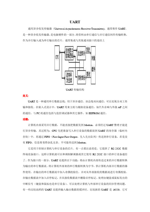
UART通用异步收发传输器(Universal Asynchronous Receiver/Transmitter),通常称作UART,是一种异步收发传输器,是电脑硬件的一部分。
将资料由串行通信与并行通信间作传输转换,作为并行输入成为串行输出的芯片,通常集成与其他通讯接口的连结上UART传输结构定义:UART是一种通用串行数据总线,用于异步通信。
该总线双向通信,可以实现全双工传输和接收。
在嵌入式设计中,UART用来主机与辅助设备通信,如汽车音响与外接AP之间的通信,与PC机通信包括与监控调试器和其它器件,如EEPROM通信。
功能:计算机内部采用并行数据,不能直接把数据发到Modem,必须经过UART整理才能进行异步传输,其过程为:CPU先把准备写入串行设备的数据放到UART的寄存器(临时内存块)中,再通过FIFO(First Input First Output,先入先出队列)传送到串行设备,若是没有FIFO,信息将变得杂乱无章,不可能传送到Modem。
它是用于控制计算机与串行设备的芯片。
有一点要注意的是,它提供了RS-232C数据终端设备接口,这样计算机就可以和调制解调器或其它使用RS-232C接口的串行设备通信了。
作为接口的一部分,UART还提供以下功能:将由计算机内部传送过来的并行数据转换为输出的串行数据流。
将计算机外部来的串行数据转换为字节,供计算机内部并行数据的器件使用。
在输出的串行数据流中加入奇偶校验位,并对从外部接收的数据流进行奇偶校验。
在输出数据流中加入启停标记,并从接收数据流中删除启停标记。
处理由键盘或鼠标发出的中断信号(键盘和鼠标也是串行设备)。
可以处理计算机与外部串行设备的同步管理问题。
有一些比较高档的UART还提供输入输出数据的缓冲区,比较新的UART是16550,它可以在计算机需要处理数据前在其缓冲区内存储16字节数据,而通常的UART是8250。
如果您购买一个内置的调制解调器,此调制解调器内部通常就会有16550 UART。
【总线】UART、Modbus、I2C、SPI、RS232、RS485及串口通讯常用参数

【总线】UART、Modbus、I2C、SPI、RS232、RS485及串⼝通讯常⽤参数⼀、UART异步收发传输,作为集成于微处理器中的周边设备,把并⾏输⼊信号转成串⾏输出信号,(⼀般是RS-232C规格的,与类似Maxim的MAX232之类的标准信号幅度变换芯⽚进⾏搭配)作为连接外部设备的接⼝。
该总线双向通信,可以实现全双⼯传输和接收。
在嵌⼊式设计中,UART⽤于主机与辅助设备通信,如与PC机通信包括与监控调试器和其它器件,如EEPROM通信。
⼀个字符接着⼀个字符传输,⼀个字符的信息由起始位、数据位、奇偶校验位和停⽌位组成。
传输时低位在前⾼位在后。
发送端和接收端必须按照相同的字节帧格式和波特率进⾏通信。
UART的设计采⽤模块化的设计思想,主要分为 3个模块:数据发送模块、数据接收模块及波特率发⽣器控制模块。
发送模块实现数据由并⾏输⼊到串⾏输出,接收模块实现数据由串⾏输⼊到并⾏输出,波特率发⽣器模块控制产⽣UART时钟频率。
发送逻辑对从发送FIFO读取的数据执⾏“并→串”转换。
控制逻辑输出起始位在先的串⾏位流,并且根据控制寄存器中已编程的配置,后⾯紧跟着数据位(注意:最低位 LSB 先输出)、奇偶校验位和停⽌位。
在检测到⼀个有效的起始脉冲后,接收逻辑对接收到的位流执⾏“串→并”转换。
此外还会对溢出错误、奇偶校验错误、帧错误和线中⽌(line-break)错误进⾏检测,并将检测到的状态附加到被写⼊接收FIFO的数据中。
需要两根信号线和⼀根地线。
⼆、Modbus1、ASCII模式与RTU模式的区别(1)ASCII:消息中每个ASCII字符都是⼀个⼗六进制字符组成(2)RTU:消息中每个8位域都是两个⼗六进制字符组成在同样波特率下,RTU可⽐ASCII⽅式传输更多的数据三、RS232、RS485(1)RS232RS232接⼝可以实现点对点的通信⽅式,但这种⽅式不能实现联⽹功能。
个⼈计算机上的通讯接⼝之⼀,异步传输标准接⼝。
uart串口参数
uart串口参数UART(通用异步收发传输器)串口参数在通信过程中起着关键作用,主要包括波特率、数据位、奇偶校验位和停止位等方面。
1. 波特率:表示每秒传输的码元数,是衡量串口通信速度的重要指标。
常用的波特率有1200、2400、9600、19200、115200等。
为保证通信的正常进行,双方设备需设定相同的波特率。
2. 数据位:指传输开始至结束所发送数据的位数。
默认的数据位为8位,但在某些特定场景下,可选择5、6、7、8位。
3. 停止位:在每字节传输结束后发送停止位,以标志数据传输的完成。
停止位的设置取决于通信双方的约定,一般设置为1位,也可选择1.5位或2位。
4. 奇偶校验位:用于检验数据传输的正确性。
通常情况下,UART通信并不使用奇偶校验位,但在一些对数据可靠性要求较高的场景中,可以启用奇偶校验以提高数据传输的可靠性。
5. 超时时间:在某些情况下,通信双方可能会在一定时间内无法正常传输数据。
为了解决这个问题,可以设置超时时间,当超过该时间后,通信双方会自动重试连接。
超时时间的设置取决于具体的应用场景和需求。
6. 硬件流控制:硬件流控制是一种避免数据传输中断的技术。
当发送方发送数据时,如果接收方没有准备好接收数据,硬件流控制机制会自动暂停数据的发送,等待接收方准备好后再继续发送。
这样可以保证数据的完整性和可靠性。
在进行UART通信时,需要根据具体的硬件设备和通信协议来设置这些参数。
例如,某些设备可能不支持硬件流控制,而其他设备则可能支持多种不同的流控制机制。
因此,在配置UART 通信参数时,需要仔细阅读相关硬件或协议文档,并根据实际需求进行合理设置。
总之,正确配置UART串口参数是保证通信质量和数据传输可靠性的关键。
在设置这些参数时,需要考虑具体的硬件设备和应用场景,以确保通信的稳定性和可靠性。
UART串行口简介
UART异步串行口UART异步串行口简介数据通信的基本方式可分为并行通信与串行通信两种:并行通信:是指利用多条数据传输线将一个资料的各位同时传送。
它的特点是传输速度快,适用于短距离通信,但要求通讯速率较高的应用场合。
串行通信:是指利用一条传输线将资料一位位地顺序传送。
特点是通信线路简单,利用简单的线缆就可实现通信,降低成本,适用于远距离通信,但传输速度慢的应用场合。
UART 异步串行口的传输格式异步通信以一个字符为传输单位,通信中两个字符间的时间间隔是不固定的,然而在同一个字符中的两个相邻位代码间的时间间隔是固定的。
通信协议(通信规程):是指通信双方约定的一些规则。
在使用异步串口传送一个字符的信息时,对资料格式有如下约定:规定有空闲位、起始位、资料位、奇偶校验位、停止位。
通讯时序图如下:开始前,线路处于空闲状态,送出连续“1”。
传送开始时首先发一个“0”作为起始位,然后出现在通信线上的是字符的二进制编码数据。
每个字符的数据位长可以约定为5 位、6 位、7 位或8 位,一般采用ASCII 编码。
后面是奇偶校验位,根据约定,用奇偶校验位将所传字符中为“1”的位数凑成奇数个或偶数个。
也可以约定不要奇偶校验,这样就取消奇偶校验位。
最后是表示停止位的“1”信号,这个停止位可以约定持续1 位、1.5 位或2 位的时间宽度。
至此一个字符传送完毕,线路又进入空闲,持续为“1”。
经过一段随机的时间后,下一个字符开始传送才又发出起始位。
每一个数据位的宽度等于传送波特率的倒数。
微机异步串行通信中,常用的波特率为110,150,300,600,1200,2400,4800,9600 ,19200,38400,115200等。
S3C2410的异步串行口1S3C2410 的UART(通用异步串行口)单元提供三个独立的异步串行I/O 端口,每个都可以在中断和DMA 两种模式下进行。
UART支持的最高波特率达230.4kbps。
uart串口通信协议的传输距离__概述及解释说明

uart串口通信协议的传输距离概述及解释说明1. 引言1.1 概述UART串口通信是一种常见的串行通信协议,被广泛应用于各种电子设备和嵌入式系统中。
它通过将数据位逐个顺序地发送到数据总线上,再由接收端进行解析和处理,实现了设备之间可靠的数据传输。
在实际应用中,传输距离是一个重要的考量因素,决定了UART协议的可靠性和稳定性。
1.2 文章结构本文将围绕UART串口通信协议的传输距离展开讨论。
首先介绍UART协议的基本概念和工作原理,然后分析影响UART传输距离的主要因素,包括线缆质量和长度、噪声干扰和抗干扰能力以及整体系统设计与电路布局等方面。
接着探讨提高UART传输距离的方法和技巧,如使用信号放大器或驱动器、选择合适的线缆和接头以及调整串口参数和波特率等策略。
最后对本文进行总结,并展望UART传输距离未来发展的可能方向。
1.3 目的本文旨在全面解释和说明UART串口通信协议的传输距离问题,帮助读者更好地理解UART协议在不同传输距离下的性能特点和应用场景。
通过分析主要的影响因素和提出相关方法和技巧,读者可以更加准确地评估和选择适合自己需求的UART传输距离解决方案。
同时,本文也为未来UART传输距离的研究和发展提供了一定的参考。
2. UART串口通信协议:2.1 串口通信概述串口通信是一种常见的数据传输方式,它通过一对数据线来实现信息的收发。
UART(Universal Asynchronous Receiver/Transmitter)是一种常用的串口通信协议,被广泛应用于计算机、嵌入式系统以及各种设备之间的数据传输。
2.2 UART协议简介UART协议是一种异步的串口通信协议,它将数据分成连续的比特流进行传输。
该协议使用起始位、数据位、校验位和停止位来组织和解析数据。
起始位指示了一个数据帧的开始,而停止位则表示一个数据帧的结束。
通过这些控制位,UART 能够在发送端和接收端之间建立正确的握手序列,并确保传输过程中的可靠性。
单片机—UART接口知识简介(上)
单片机—UART接口知识简介(上)1 UART接口简述UART即通用异步收发器,可设置成全双工异步通讯方式,与PC 等通讯;或设置成半双工同步模式与其他周边外设通信,如A/D或D /A。
SPMC65系列单片机内置了UART模块,它的作用是将外部设备串行数据转换为并行数据接收;将内部并行数据转换为串行数据发送。
UART模块特点如下:·两个接口引脚。
RXD为数据接收引脚(与PC5复用,使用RX功能时设置为输入口);TXD为数据发送引脚(与PC4复用,使用TX功能时设置为输出口)。
·提供标准的异步全双工通信。
·可编程的波特率。
·可进行偶校验、奇校验或禁止校验。
·停止位可设置为1位或2位。
·支持发送中断。
·支持接收中断。
·高抗噪声能力的数据接收(接收中间连续进行3次采样,并对结果进行多数决策)。
·在接收中进行帧校验和奇偶校验。
·溢出检测。
·CPU工作频率为8 MHz时,波特率可在2 400~38 400 bps之间编程设置。
UART的数据帧如图6.5所示。
UART接口通常用于与PC通信,或者用于单片机间的通信。
2 控制寄存器1.UART控制寄存器P_UART_Ctrl($46,R/W)可以通过写UART控制寄存器P_UART_Ctrl($46)对UART的中断使能、UART功能、帧格式等进行设置。
P_UART_Ctrl默认初始值为#00h,具体位的功能如表6.8所列。
bit7 RXIE:接收中断使能位。
1=使能;0=禁止。
bit6 TXIE:发送中断使能位。
1=使能;0禁止。
bit5 RXEN:UART接收功能使能位。
1=使能;0=禁止。
bit4 TXEN:UART发送功能使能位。
1=使能;0=禁止。
bit3 SOFTRST:软件复位。
写:1=复位所有UART模块;0=无效。
bit2 STOPSEL:停止位长度选择位。
串口双机uart通信的工作原理
串口双机UART通信的基本原理1. 介绍串口通信是一种常见的数据交互方式,常用于连接计算机和外部设备。
串口双机通信是指两个设备之间通过串口进行数据交互。
其中,UART(通用异步收发传输器)是一种常用的串口通信协议。
2. UART通信的基本原理UART通信基于电子电路的传输原理。
下面将详细解释UART通信的基本原理。
2.1 串口的物理连接两个设备之间的UART通信需要通过串口物理接口连接。
一般来说,串口接口由两个信号线组成:发送数据线(Tx)和接收数据线(Rx)。
这两条线是一对一的关系,即发送数据线连接到接收数据线上。
2.2 数据的传输方式UART通信使用异步传输方式,即数据是按照字节的形式逐位传输的。
每个字节由起始位、数据位、校验位和停止位组成。
•起始位:用于指示数据传输的开始。
一般为低电平(0)。
•数据位:用于传输实际的数据。
常用的数据位数有8位。
•校验位:用于检测传输过程中数据的一致性。
常用的校验位有奇偶校验和无校验。
奇偶校验可以检测数据传输过程中的错误。
•停止位:用于标识数据传输的结束。
一般为高电平(1)。
2.3 数据的传输和接收过程UART通信的传输和接收过程如下:1.发送端开始传输数据时,先发送起始位(低电平)。
2.然后按照数据位长度,逐位发送数据。
3.发送完数据位后,发送校验位。
4.最后发送停止位(高电平)。
5.接收端在接收到起始位后开始接收数据。
6.根据数据位长度,逐位接收数据。
7.接收完数据位后,接收校验位。
8.最后接收停止位。
2.4 波特率UART通信中的波特率是指数据传输的速率,即每秒传输的比特数。
波特率越高,传输速度越快。
常用的波特率有9600、115200等。
2.5 时钟同步UART通信中,发送端和接收端需要基于相同的时钟来进行数据的传输和接收。
时钟同步是通过波特率来实现的。
3. 串口双机通信的实现步骤要实现串口双机通信,需要按照以下步骤进行:1.硬件连接:将两个设备的串口接口通过串口线连接起来。
UART串口通信协议
UART串⼝通信协议⼀、UART简介 UART(universal asynchronous receiver-transmitter)是⼀种采⽤异步串⾏通信⽅式的通⽤异步收发传输器。
⼀般来说,UART总是和RS232成对出现,那RS232⼜是什么呢? RS232也就是我们计算机上的串⼝,它的全称是EIA-RS-232C (简称232,或者是RS232 )。
其中EIA(Electronic Industry Association)代表美国电⼦⼯业协会,RS是Recommended Standard的缩写,代表推荐标准,232 是标识符,C表⽰修改次数,它被⼴泛⽤于计算机串⾏接⼝外设连接。
如果你的计算机上还有串⼝的话,那么你就可以在主机箱后⾯看到RS232的接⼝: 随着时代的发展,这种借⼝已经很少⽤了,取⽽代之的是“USB转串⼝”,功能和原先⼀样,但接⼝更⾼效了。
串⼝的主要功能为:在发送数据时将并⾏数据转换成串⾏数据进⾏传输,在接收数据时将接收到的串⾏数据转换成并⾏数据。
这应该是⼤多数⼈接触电⼦后学习到的第⼀个通信协议吧。
串⼝参数(通信双⽅约定好)波特率:发送和接收⼀个bit都有固定的速率—9600bps 19200bps 38400bps 57600bps 115200bps。
起始位:先发出⼀个逻辑”0”的信号,表⽰传输数据的开始。
数据位:可以是5~8位逻辑”0”或”1”。
如ASCII码(7位),扩展BCD码(8位)。
⼩端传输。
校验位:数据位加上这⼀位后,使得“1”的位数应为偶数(偶校验)或奇数(奇校验),以此来校验数据传送的正确性。
停⽌位:它是⼀个字符数据的结束标志。
⼆、通信格式 下⾯来说说串⼝的具体要点:1.传输时序 UART串⼝通信需要两个信号线来实现,⼀根⽤于串⼝发送,另外⼀根负责串⼝接收。
⼀开始⾼电平,然后拉低表⽰开始位,接着8个数据位,然后校验位,最后拉⾼表⽰停⽌位,并且进⼊空闲状态,等待下⼀次的数据传输。
UART——精选推荐
UART一、串口的历史首先,串口对每一个做硬件和嵌入式软件的人来说,就是一个必备的工具,调试一个带MCU或者CPU的系统。
我们在调试的过程中,一般第一件事情:GPIO点灯,第二件事就是打通串口。
串口是一种非常通用的设备接口,是仪器仪表设备常用的通信接口,常用于远程采集设备数据或者实现远程控制。
串口的开发也比较简单,是很多工程师最喜欢的接口之一。
在完成GPIO点灯之后,一般我们就希望能够实现串口打印的功能,便于我们将一些寄存器信息打印出来便于调试。
由于我个人的特殊经历,对于我来说,串口这东西,仔细写起来,可以写一本书!应该不少于200页。
2008年我刚进华为工作时,碰到了一个特殊的历史时期,嵌入式领域群雄逐鹿。
1、Intel、AMD高调宣称X86系统进入嵌入式领域,要占领PowerPC的市场。
(后来Intel也做到了,通用服务器占领了几乎所有电信核心侧的设备——刀片服务器、机架服务器)。
2、当时,MIPS、ARM、PowerPC还难分伯仲,不过多核ARM不成熟,无法在电信领域广泛应用。
MIPS由于其优异的性价比和高性能展露头角,慢慢由于其较差的质量表现而偃旗息鼓。
3、PowerPC,随着来着其他处理器的压力,也开始推出多核处理器。
我当时的工作是参与X86处理器作为嵌入式的电路开发。
当时碰到一个问题:传统X86作为PC机已经演进得非常成熟的架构。
PC的硬件结构与嵌入式SoC有很大的区别。
CPU下面是北桥负责高速外设、北桥的南面(下面)是南桥负责低速接口外设、然后还有一个SIO负责更低速的外设。
SIO全称叫Super I/O。
超级输入输出芯片(SIO)一般位于主板左下方或者左上方。
主要使用的芯片有Winbond、ITE,它为主板上的标准I/O接口提供控制处理功能。
这里所说的“超级”是指它集成了PS/2键盘、PS/2鼠标、串口COM、并口LPT接口等处理功能,而这些接口都是计算机中的慢速I/O设备。
它们全部位于主板后部右边。
- 1、下载文档前请自行甄别文档内容的完整性,平台不提供额外的编辑、内容补充、找答案等附加服务。
- 2、"仅部分预览"的文档,不可在线预览部分如存在完整性等问题,可反馈申请退款(可完整预览的文档不适用该条件!)。
- 3、如文档侵犯您的权益,请联系客服反馈,我们会尽快为您处理(人工客服工作时间:9:00-18:30)。
Application NoteSpecifications subject to change without notice, contact your sales representatives for the most recent information. UART 功能使用方法1 適用產品:SM59R16A2 / SM59R08A22 UART 使用概述:2.1 提供兩組串通訊列埠 (UART0, UART1)2.2 每一組UART 分別有獨立的緩衝記憶體,且傳送及接收則是共用.UART0 使用S0BUF UART1 使用S1BUF當執行資料接收時,必須在前一筆資料完成執行工作後,否則會造成資料流失的問題;可由送傳中斷旗標或接收中斷旗標判斷是否完成執行工作的狀態.2.3 當使用串通訊列埠時,系統時脈來源建議使用外部晶振.由於內部晶振頻率的誤差約為+5%,當使用串通訊列埠時,系統時脈必須要求晶振頻率的誤差約為+2%.3 以下說明與UART 相關的特殊控制暫存器及特殊狀態暫存器Special Function Register (SFR)Mnemonic Description DirectBit 7Bit 6Bit 5Bit 4Bit 3Bit 2Bit 1Bit 0RESE TSerial interface 0 and 1PCON Power control 87h SMOD MDUF - PMW - - STOP IDLE 00hBRGS Baud rategenerator switch D8h BRS - - - - - - - 00hS0CON Serial Port 0control register 98h SM0 SM1 SM20REN0TB80 RB80 TI0 RI0 00hS0RELL Serial Port 0reload register low byte AAh S0REL .7 S0REL .6 S0REL .5 S0REL .4 S0REL .3 S0REL .2 S0REL .1 S0REL.000hS0RELH Serial Port 0reload registerhigh byte BAh - - - - - - S0REL .9 S0REL.800h S0BUF Serial Port 0data buffer 99h S0BUF[7:0] 00hS1CON Serial Port 1control register 9Bh SM - SM21REN1TB81 RB81 TI1 RI1 00hS1RELL Serial Port 1reload register low byte 9Dh S1REL .7 S1REL .6 S1REL .5 S1REL .4 S1REL .3 S1REL .2 S1REL .1 S1REL.000hS1RELH Serial Port 1reload registerhigh byte BBh - - - - - - S1REL .9 S1REL.800h S1BUF Serial Port 1data buffer9Ch S1BUF[7:0] 00hApplication NoteSpecifications subject to change without notice, contact your sales representatives for the most recent information.Mnemonic: S0CON Address: 98h 7 6 5 4 3 2 1 0 Reset SM0 SM1 SM20 REN0TB80 RB80TI0 RI0 00hSM0,SM1: 串列通訊埠0(UART0)模式選擇(Serial Port 0 mode selection.)SM0 SM1 Mode 0 0 0 0 1 1 1 0 2 1 1 3SM20: 多處理機通訊致能旗標(Enables multiprocessor communication feature.) 串列埠工作模式2和3時,可致能多工處理器通訊的功能。
在模式2或3,如果SM2=1,則當接收到的第9資料位元為0時,RI 不動作。
在模式1時,若SM2=1,當接收到的停止位元不正確時,RI 則不動作。
在模式0時,SM2必須為0。
REN0: 接收致能旗標:“1” – 致能。
“0” – 禁能,必須由軟體清除。
TB80: 在傳送模式2和模式3時,所傳送的資料的第9位元(9th -bit)The 9th transmitted data bit in modes 2 and 3.Set or cleared by the CPU depending on the function it performs such as parity check, multiprocessor communication etc.RB80: 在傳送模式2和模式3時,所接收的資料的第9位元(9th -bit)在傳送模式1時,如果SM20為0,則RB80為停止位元(stop bit) 在傳送模式0時,RB80無作用 此位元必須由軟體清除。
TI0: 傳送中斷旗標(Transmit interrupt flag):在模式0時,在第8位元結束時,硬體會將它設為1; 其他模式時,在stop bit 停止位元的開始時設定為1。
“1” – 傳送完成由硬體設置。
“0” – 必須由軟體清除。
RI0: 接收中斷旗標(Receive interrupt flag)在模式0時,在第8位元結束時,硬體會將它設為1,其他模式時,在stop bit 停止位元的一半的時候由硬體設定 “1” – 接收完成由硬體設置。
“0” – 必須由軟體清除。
須參考SM20。
Mnemonic: S1CON Address: 9Bh 7 6 5 4 3 2 1 0 Reset SM - SM21 REN1TB81 RB81TI1 RI1 00hSM: 串通訊列埠1(UART1)模式選擇(Serial Port1 mode selection.)SM Mode 0 A 1 BSM21: 多處理機通訊致能旗標(Enables multiprocessor communication feature.)串列埠工作模式2和3時,可致能多工處理器通訊的功能。
Application NoteSpecifications subject to change without notice, contact your sales representatives for the most recent information. 在模式2或3,如果SM2=1,則當接收到的第9資料位元為0時,RI 不動作。
在模式1時,若SM2=1,當接收到的停止位元不正確時,RI 則不動作。
在模式0時,SM2必須為0。
REN1: 接收致能旗標:“1” – 致能。
“0” – 禁能,必須由軟體清除。
TB81: 在傳送模式2和模式3時,所傳送的資料的第9位元(9th -bit)The 9th transmitted data bit in mode A. Set or cleared by the CPU depending on the function it performs such as parity check, multiprocessor communication etc.RB81: 在傳送模式A 時,所接收的資料的第9位元(9th -bit)在傳送模式B 時,如果SM21為0,則RB81為停止位元(stop bit) 此位元必須由軟體清除。
TI1: 傳送中斷旗標(Transmit interrupt flag)在模式0時,在第8位元結束時,硬體會將它設為1。
其他模式時,在stop bit 停止位元的開始時設定為1。
“1” – 傳送完成由硬體設置。
“0” – 必須由軟體清除。
RI1: 接收中斷旗標(Receive interrupt flag)在模式0時,在第8位元結束時,硬體會將它設為1,其他模式時,在stop bit 停止位元的一半的時候由硬體設定 “1” – 接收完成由硬體設置。
“0” – 必須由軟體清除。
須參考SM21。
3.1 Serial interface 0(UART0) modes 1 and 3(a) When BRS = 0 (in SFR BRGS):()TH12561232F 2 Rate Baud SMOD −×××=OSC(b) When BRS = 1 (in SFR BRGS):()S0REL264F 2Rate Baud 10OSCSMOD −××=3.2 Serial interface 1(UART1) modes A and B()S1REL232FRate Baud 10OSC−×=Application NoteSpecifications subject to change without notice, contact your sales representatives for the most recent information. 4 UART0(Serial interface 0)串列通訊埠UART0有以下四種操作模式:SM0 SM1 Mode Description Board Rate Baud Rate generate0 0 0 Shift register Fosc/12 fixed0 1 1 8-bit UART Variable baud rate generator ortimer 11 02 9-bit UART Fosc/32 or Fosc/64 fixed1139-bit UARTVariablebaud rate generator or timer 1Fosc 指crystal 或oscillator 的振盪頻率。
4.1.1 Mode 01. MCU 資料輸出或輸入都是利用RXD0為引腳。
TXD0為MCU 輸出移位時脈(固定為Fosc/12)。
2. 資料為8 bits ,由LSB 先傳送。
3. 固定鮑率(Baud rate)為Fosc/12。
4. Mode 0初始化由旗標S0CON 設定:RI0 = 0 and REN0 = 1。
5. 當傳送資料時:須先以軟體清除S0CON中的REN0=0,執行資料寫入S0BUF指令,則會引發資料傳送的動作;資料傳送完畢後,MCU會將S0CON中的TI0設定為1,通知中斷產生。
