电池参数设置
电池组件参数修改补充
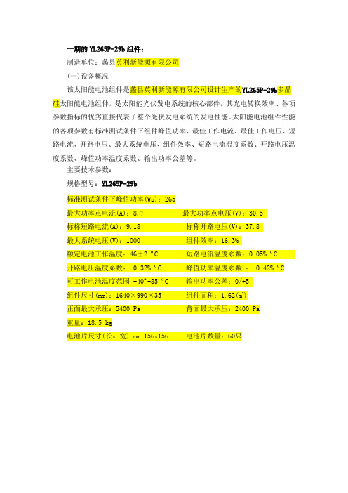
一期的YL265P-29b组件:
制造单位:蠡县英利新能源有限公司
(一)设备概况
该太阳能电池组件是蠡县英利新能源有限公司设计生产的YL265P-29b多晶
硅太阳能电池组件,是太阳能光伏发电系统的核心部件,其光电转换效率、各项
参数指标的优劣直接代表了整个光伏发电系统的发电性能。
太阳能电池组件性能
的各项参数有标准测试条件下组件峰值功率、最佳工作电流、最佳工作电压、短
路电流、开路电压、最大系统电压、组件效率、短路电流温度系数、开路电压温
度系数、峰值功率温度系数、输出功率公差等。
主要技术参数:
规格型号:YL265P-29b
标准测试条件下峰值功率(Wp):265
最大功率点电流(A):8.7 最大功率点电压(V):30.5
标称短路电流(A):9.18 标称开路电压(V):37.8
最大系统电压(V):1000 组件效率:16.3%
额定电池工作温度:46±2 ºC 短路电流温度系数:0.05% ºC 开路电压温度系数:-0.32% ºC 峰值功率温度系数:-0.42% ºC
可工作电池温度范围 -40~+85 ºC 输出功率公差:0/+5
组件尺寸(mm):1640×990×35 组件面积:1.62(m2)
正面最大承压:5400 Pa 背面最大承压:2400 Pa
重量:18.5 kg
电池片尺寸(长x 宽) mm 156x156 电池片数量:60只。
嘉佰达锂电池保护板电流电压参数设置

嘉佰达锂电池保护板电流电压参数设置嘉佰达锂电池保护板电流电压参数设置引言:嘉佰达锂电池保护板是一种广泛应用于各种锂电池系统中的重要元件。
它的功能是对锂电池进行保护,以防止过充、过放、过流和短路等可能会对电池造成损坏的情况。
为了实现最佳的电池性能和安全性,正确设置锂电池保护板的电流和电压参数是至关重要的。
在本文中,我们将深入探讨嘉佰达锂电池保护板电流电压参数的设置原则和方法,并提供我们对该主题的观点和理解。
一、电流电压参数的重要性电流和电压是嘉佰达锂电池保护板中最关键的参数之一。
正确设置这些参数可以确保锂电池在充放电过程中的性能和安全性。
如果电流参数设置不当,电池可能会过载或过放,从而导致电池容量下降、寿命缩短甚至电池故障。
而错误的电压参数设置可能会引起重要的安全问题,例如过充或过放可能导致电池爆炸或火灾。
二、电流参数设置原则1. 充电电流:嘉佰达锂电池保护板通常都允许设置最大充电电流。
一般来说,建议根据电池容量的比例来设置充电电流。
较大容量的电池可以使用较大的充电电流,而较小容量的电池则应使用较小的充电电流。
这样可以确保电池的安全性和寿命。
2. 放电电流:放电电流的设置要根据具体应用来决定。
一般来说,嘉佰达锂电池保护板允许设置最大放电电流。
但为了确保电池的安全和性能,放电电流不应超过电池的额定电流。
放电电流也应根据电池的最大承受能力进行合理的设置。
三、电压参数设置原则1. 充电终止电压:充电终止电压是指锂电池达到充满状态时的电压。
嘉佰达锂电池保护板的充电终止电压应根据锂电池的规格和制造商的建议进行设置。
一般来说,锂电池的充电终止电压在4.2V左右。
如果将充电终止电压设置得过高,可能会导致电池充电过度,从而影响电池寿命和安全性。
2. 放电终止电压:放电终止电压是指锂电池放电到所允许最低电压时终止放电的电压。
嘉佰达锂电池保护板的放电终止电压应根据锂电池的规格和制造商的建议进行设置。
一般来说,锂电池的放电终止电压在3.0V左右。
APC小机电池参数设置

SRC5K-10K如何设置电池参数"1.配置原配电池包的参数设置方法:SRC5000/6000使用的原配电池包型号为SRC192XLBPSRC8000使用的原配电池包型号为SRC240XLBP1SRC10000使用的原配电池包型号为SRC240XLBP2a.选择到“configuration ”菜单中;b.按“v”键(向下键),找到子菜单“Menu Type”,此项的选择默认为“Normal”,按回车键将此项改为“Advanced”;c.仍然在“configuration ”菜单中,按“v”键(向下键),找到“External Battery Packs”项,在这项里做设置。
例如:SRC8000UXICH+SRC240XLBP1(1个),需要将此项改为:12.配置非原配电池包的参数设置方法:a.选择到“configuration ”菜单中;b.按“v”键(向下键),找到子菜单“Menu Type”,此项的选择默认为“Normal”,按回车键将此项改为“Advanced”;c.仍然在“configuration ”菜单中,按“v”键(向下键),直到找到“External Battery Total AH”,在这项里做设置。
例如:SRC8000UXICH外接了20个12V,9AH的电池,需要设定的AH数为20*9=180,需要将此项改为:180"APC在线互动式UPS中,根据电路设计不同,可以分为不能外带电池的标准延时机型和可以外接电池的长延时机型。
区分方法是:凡是型号中含有UX或XL字母的,均是长延时型号。
标机不能外接电池进行长延时,而长机则可外接电池进行长延时,长延时机第一次安装或改变外接电池时均需设置初始电池参数才能达到长延时效果,电池参数设置方法如下: a. 将UPS串口用APC原配RS-232电缆(940-0024C或940-1524C)与计算机串口联接。
b. 进入WIN95,WIN3.1,WIN98,WINNT附件中的Hyperterminal(超级终端),选择有关Communication Setting的选项。
电池参数设置(相关知识)

DescriptionThe Battery block implements a generic dynamic model parameterized to represent most popular types of rechargeable batteries.The equivalent circuit of the battery is shown below:Lead-Acid ModelDischarge model (i* > 0)f1(it,i∗,i,Exp)=E0−K⋅QQ−it⋅i∗−K⋅QQ−it⋅it+Laplace−1(Exp(s)Sel(s)⋅0).Charge Model (i* < 0)f2(it,i∗,i,Exp)=E0−K⋅Qit+0.1⋅Q⋅i∗−K⋅QQ−it⋅it+Laplace−1(Exp(s)Sel(s)⋅1s).Lithium-Ion ModelDischarge Model (i* > 0)f1(it,i∗,i)=E0−K⋅QQ−it⋅i∗−K⋅QQ−it⋅it+A⋅exp(−B⋅it).Charge Model (i* < 0)f2(it,i∗,i)=E0−K⋅Qit+0.1⋅Q⋅i∗−K⋅QQ−it⋅it+A⋅exp(−B⋅it).Nickel-Cadmium and Nickel-Metal-Hydride ModelDischarge Model (i* > 0)f1(it,i∗,i,Exp)=E0−K⋅QQ−it⋅i∗−K⋅QQ−it⋅it+Laplace−1(Exp(s)Sel(s)⋅0).Charge Model (i*< 0)f2(it,i∗,i,Exp)=E0−K⋅Q↓↓it↓↓+0.1⋅Q⋅i∗−K⋅QQ−it⋅it+Laplace−1(Exp(s)Sel(s)⋅1s),where,E Batt = Nonlinear voltage (V)E0 = Constant voltage (V)Exp(s)= Exponential zone dynamics (V)Sel(s)= Represents the battery mode. Sel(s) = 0 during battery discharge, Sel(s) = 1 during battery charging.K = Polarization constant (Ah−1) or Polarization resistance (Ohms)i* = Low frequency current dynamics (A)i = Battery current (A)it = Extracted capacity (Ah)Q = Maximum battery capacity (Ah)A = Exponential voltage (V)B = Exponential capacity (Ah)−1The parameters of the equivalent circuit can be modified to represent a particular battery type, based on its discharge characteristics. A typical discharge curve is composed of three sections, as shown in the next figure:The first section represents the exponential voltage drop when the battery is charged. Depending on the battery type, this area is more or less wide. The second section represents the charge that can be extracted from the battery until the voltage drops below the battery nominal voltage. Finally, the third section represents the total discharge of the battery, when the voltage drops rapidly.When the battery current is negative, the battery will recharge following a charge characteristic as shown below:Note that the parameters of the model are deduced from discharge characteristics and assumed to be the same for charging.The Exp(s) transfer function represents the hysteresis phenomenon for the Lead-Acid, NiCD and NiMH batteries during charge and discharge cycles. The exponential voltage increases when battery is charging, no matter the SOC of the battery. When the battery is discharging, the exponential voltage decreases immediately:Dialog Box and ParametersParameters TabBattery typeProvides a set of predetermined charge behavior for four types of battery:•Lead-Acid•Lithium-Ion•Nickel-Cadmium•Nickel-Metal-HydrideNominal Voltage (V)The nominal voltage (Vnom) of the battery (volts). The nominal voltage represents the end of the linear zone of the discharge characteristics.Rated Capacity (Ah)The rated capacity (Qrated) of the battery in ampere-hour. The rated capacity is the minimum effective capacity of the battery.Initial State-Of-Charge (%)The initial State-Of-Charge (SOC) of the battery. 100% indicates a fully charged battery and 0% indicates an empty battery. This parameter is used as an initial condition for the simulation and does not affect the discharge curve (when the option Plot Discharge Characteristics is used). Use parameters based on Battery type and nominal valuesLoad the corresponding parameters in the entries of the dialog box, depending on the selected Battery type, the Nominal Voltage and the Rated Capacity.When a preset model is used, the detailed parameters cannot be modified. If you want to modify the discharge curve, select the desired battery type to load the default parameters, and then uncheck the Use parameters based on Battery type and nominal values checkbox to access the detailed parameters.Maximum Capacity (Ah)The maximum theoretical capacity (Q), when a discontinuity occurs in the battery voltage. This value is generally equal to 105% of the rated capacity.Fully charged Voltage (V)The fully charged voltage (Vfull), for a given discharge current. Note that the fully charged voltage is not the no-load voltage.Nominal Discharge Current (A)The nominal discharge current, for which the discharge curve has been measured. For example, a typical discharge current for a 1.5 Ah NiMH battery is 20% of the rated capacity: (0.2 * 1.5 Ah / 1h = 0.3A).Internal ResistanceThe internal resistance of the battery (ohms). When a preset model is used, a generic value is loaded, corresponding to 1% of the nominal power (nominal voltage * rated capacity of the battery). The resistance is supposed to be constant during the charge and the discharge cycles and does not vary with the amplitude of the current.Capacity (Ah) @ Nominal VoltageThe capacity (Qnom) extracted from the battery until the voltage drops under the nominal voltage. This value should be between Qexp and Qmax.Exponential zone [Voltage (V), Capacity (Ah)]The voltage (Vexp) and the capacity (Qexp) corresponding to the end of the exponential zone. The voltage should be between Vnom and Vfull. The capacity should be between 0 and Qnom.View Discharge Characteristics TabPlot Discharge CharacteristicsClick to plot a figure containing two graphs. The first graph represents the nominal discharge curve (at the Nominal Discharge Current) and the second graph represents the discharge curves at the specified discharge currents.Discharge currentAllows to specify different values of discharge current. The discharge characteristics for these currents are presented in the second part of the graph.。
全志电池参数配置说明
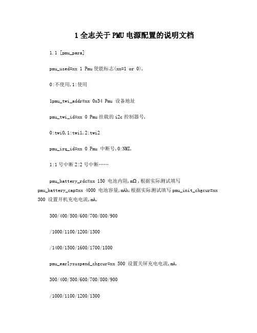
1全志关于PMU电源配置的说明文档1.1 [pmu_para]pmu_used=xx 1 Pmu使能标志(xx=1 or 0),0:不使用,1:使用1pmu_twi_addr=xx 0x34 Pmu 设备地址pmu_twi_id=xx 0 Pmu挂载的i2c控制器号,0:twi0,1:twi1,2:twi2pmu_irq_id=xx 0 Pmu 中断号,0:NMI,1:1号中断2:2号中断……pmu_battery_rdc=xx 150 电池内阻,mΩ,根据实际测试填写pmu_battery_cap=xx 4000 电池容量,mAh,根据实际测试填写pmu_init_chgcur=xx 300 设置开机充电电流,mA,300/400/500/600/700/800/900/1000/1100/1200/1300/1400/1500/1600/1700/1800pmu_earlysuspend_chgcur=xx 500 设置关屏充电电流,mA,300/400/500/600/700/800/900/1000/1100/1200/1300/1400/1500/1600/1700/1800pmu_suspend_chgcur=xx 1000 设置休眠充电电流,mA,300/400/500/600/700/800/900/1000/1100/1200/1300/1400/1500/1600/1700/1800pmu_resume_chgcur=xx 300 设置唤醒充电电流,mA,300/400/500/600/700/800/900/1000/1100/1200/1300/1400/1500/1600/1700/1800pmu_shutdown_chgcur=xx 1300 设置关机充电电流,mA300/400/500/600/700/800/900/1000/1100/1200/1300/1400/1500/1600/1700/1800pmu_init_chgvol=xx 4200 设置充电目标电压,mV,4100/4150/4200/4360pmu_init_chgend_rate=xx 15 设置结束充电电流的比率,%,10,15 pmu_init_chg_enabled=xx 1 设置充电功能,0:关闭,1:打开pmu_init_adc_freq=xx 100 设置adc采样率,Hz,25/50/100/200pmu_init_adc_freqc=xx 100 设置库仑计采样率,Hz,25/50/100/200pmu_init_chg_pretime=xx 50 设置预充电超时时间,min,40/50/60/70 pmu_init_chg_csttime=xx 720 设置恒流充电超时时间,min,360/480/600/720pmu_bat_para1=xx 设置空载电池电压对应的百分比,%,具体请看《电池参数测试操作指南》文档pmu_bat_para2=xx 设置空载电池电压对应的百分比,%,具体请看《电池参数测试操作指南》文档pmu_bat_para3=xx 设置空载电池电压对应的百分比,%,具体请看《电池参数测试操作指南》文档pmu_bat_para4=xx 设置空载电池电压对应的百分比,%,具体请看《电池参数测试操作指南》文档pmu_bat_para5=xx 设置空载电池电压对应的百分比,%,具体请看《电池参数测试操作指南》文档pmu_bat_para6=xx 设置空载电池电压对应的百分比,%,具体请看《电池参数测试操作指南》文档pmu_bat_para7=xx 设置空载电池电压对应的百分比,%,具体请看《电池参数测试操作指南》文档pmu_bat_para8=xx 设置空载电池电压对应的百分比,%,具体请看《电池参数测试操作指南》文档pmu_bat_para9=xx 设置空载电池电压对应的百分比,%,具体请看《电池参数测试操作指南》文档pmu_bat_para10=xx 设置空载电池电压对应的百分比,%,具体请看《电池参数测试操作指南》文档pmu_bat_para11=xx 设置空载电池电压对应的百分比,%,具体请看《电池参数测试操作指南》文档pmu_bat_para12=xx 设置空载电池电压对应的百分比,%,具体请看《电池参数测试操作指南》文档pmu_bat_para13=xx 设置空载电池电压对应的百分比,%,具体请看《电池参数测试操作指南》文档pmu_bat_para14=xx 设置空载电池电压对应的百分比,%,具体请看《电池参数测试操作指南》文档pmu_bat_para15=xx 设置空载电池电压对应的百分比,%,具体请看《电池参数测试操作指南》文档pmu_bat_para16=xx 设置空载电池电压对应的百分比,%,具体请看《电池参数测试操作指南》文档,建议此处固定为100pmu_usbvol_limit=xx 1 设置usb限压功能,0:关闭,1:打开pmu_usbvol=xx 4400 设置usb限压电压,mV,4000/4100/4200/4300/4400/4500/4600/4700 pmu_usbcur_limit=xx 0 设置usb限流功能,0:关闭,1:打开pmu_usbcur=xx 500 设置usb限流电流,mA,100/500/900 pmu_pwroff_vol=xx 3300 设置启动时的硬件保护电压,mV,2600/2700/2800/2900/3000/3100/3200/3300pmu_pwron_vol=xx 2900 设置开机状态下的硬件保护电压,mV,2600/2700/2800/2900/3000/3100/3200/3300 pmu_pekoff_time=xx 6000 设置硬件关机时长,ms,4000/6000/8000/10000pmu_pekoff_en=xx 1 设置硬件关机功能,0:关闭,1:打开pmu_peklong_time=xx 1500 设置长按键中断时间,ms,1000/1500/2000/2500pmu_pekon_time=xx 2000 设置开机时间,ms,128/1000/2000/3000pmu_pwrok_time=xx 64 设置电源启动完成后pwrok信号延时,ms,8/64pmu_pwrnoe_time=xx 2000 设置n_oe由低变高后关机延迟时间,ms,128/1000/2000/3000pmu_intotp_en=xx 1 设置过温关机功能,0:关闭,1:打开pmu_used2=xx 专门为佳的美案子做的一个设置,配合pmu_adpdet~ pmu_shutdown_chgcur2,打开1,关闭0pmu_adpdet=xx 佳的美案子的设置,火牛探测口设置,具体参看上面gpio的配置pmu_init_chgcur2=xx 佳的美案子的设置,插入火牛时,开机充电电流设置,同pmu_init_chgcurpmu_earlysuspend_chgcur2=xx 佳的美案子的设置,插入火牛时,关屏充电电流设置,同pmu_earlysuspend_chgcur pmu_suspend_chgcur2=xx 佳的美案子的设置,插入火牛时,休眠充电电流设置,同pmu_suspend_chgcur pmu_resume_chgcur2=xx 佳的美案子的设置,插入火牛时,唤醒充电电流设置,同pmu_resume_chgcurpmu_shutdown_chgcur2=xx 佳的美案子的设置,插入火牛时,关机充电电流设置,同pmu_shutdown_chgcur pmu_suspendpwroff_vol=xx 3400 休眠关机电压设置,mV,2867~4200,6mV一档pmu_batdeten=xx 1 电池探测功能设置,0:关闭,1:打开注意:pmu_used2~ pmu_shutdown_chgcur2之间的参数是为佳的美案子专门做的接口,对其他案子可以删掉。
常见开关电源参数设置手册

常见开关电源参数设置手册目录一.艾默生开关电源系列....................................... 错误!未定义书签。
系列监控模块 .................................................... 错误!未定义书签。
监控模块参数设置............................................. 错误!未定义书签。
二.动力源开关电源参数设置 ............................... 错误!未定义书签。
DKD31监控模块参数设置............................... 错误!未定义书签。
DKD51型系统控制操作与参数设置 ............... 错误!未定义书签。
三.中兴通讯开关电源参数设置 ........................... 错误!未定义书签。
开关电源CSU监控模块设置 .......................... 错误!未定义书签。
四.中达电通开关电源参数设置 ........................... 错误!未定义书签。
开关电源监控参数设置..................................... 错误!未定义书签。
五.珠江开关电源参数设置................................... 错误!未定义书签。
CU2000H监控模块参数设置........................... 错误!未定义书签。
六.普天洲际开关电源参数设置 ........................... 错误!未定义书签。
洲际DK04C监控模块参数 ................................ 错误!未定义书签。
一.艾默生开关电源系列系列监控模块1.电池参数(基本参数)设置方法:2.下电保护参数设置方法:3.电池充电参数设置方法:4.电池参数(电池测试参数)设置方法:5.电池参数(温补参数)设置方法:6.系统参数设置方法:7.通信参数设置方法监控模块参数设置1.模块启动说明2.直流参数:设置按“、”键选择“按电压”或“按时间”方式,按确认键确认修改。
开关电源参数设置规范
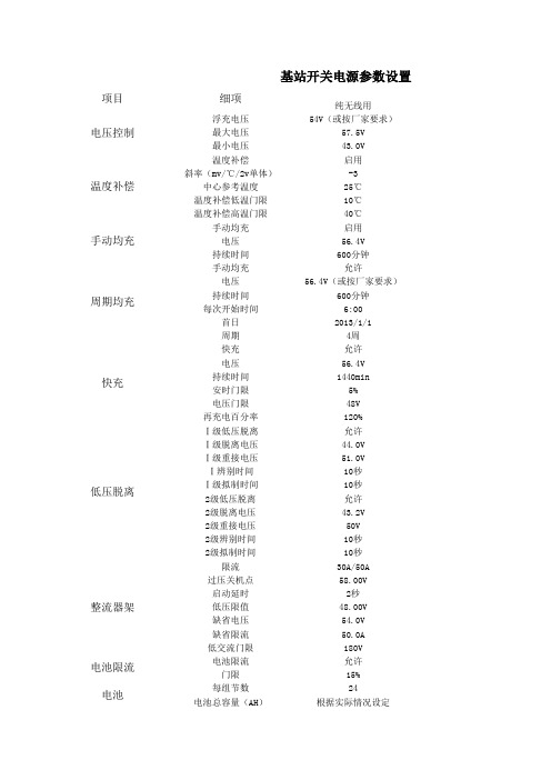
-3 25℃ 10℃ 40℃ 启用 56.4V 600分钟 允许 56.4V(或按厂家要求) 600分钟 6:00 2013/1/1 4周 允许 56.4V 1440min
5% 48V 120% 允许 46.0V 51.0V 10秒 10秒 禁止 禁止 ’’’30A/50A 58.00V 2秒 48.00V 54.0V 50.0A 180V 允许 15% 24 根据实际情况设定
项目 电压控制 温度补偿 手动均充 周期均充
快充
低压脱离
整流器架 电池限流
电池
基站开关电源参数设置
细项
浮充电压 最大电压 最小电压 温度补偿 斜率(mv/℃/2v单体) 中心参考温度 温度补偿低温门限 温度补偿高温门限 手动均充
电压 持续时间 手动均充
电压 持续时间 每次开始时间
首日 周期 快充 电压 持续时间 安时门限 电压门限 再充电百分率 Ⅰ级低压脱离 Ⅰ级脱离电压 Ⅰ级重接电压 Ⅰ辨别时间 Ⅰ级拟制时间 2级低压脱离 2级脱离电压 2级重接电压 2级辨别时间 2级拟制时间 限流 过压关机点 启动延时 低压限值 缺省电压 缺省限流 低交流门限 电池限流 门限 每组节数 电池总容量(AH)
纯无线用 54V(或按厂家要求)
57.5V 43.0V 启用
-3 25℃ 10℃ 40℃ 启用 56.4V 600分钟 允许 56.4V(或按厂家要求) 600分钟 6:00 2013/1/1 4周 允许 56.4V 1440min
5% 48V 120% 禁止 ‘‘‘‘禁止 禁止 ’’’30A/50A 58.00V 2秒 48.00V 54.0V 50.0A 180V 允许 15% 24 根据实际情况设定
57.6V 55.7V 52.8V
艾默生电池参数设置

11.1.1 设置电池参数电池参数是比较重要的参数,一定要设置正确,它关系着电池的使用寿命。
在图4-6所示的参数设置屏中按上下键选取“电池参数”选项,按确认键后进入电池参数设置屏,见下图。
电池参数基本参数下电保护充电管理电池测试温补参数图1-1 电池参数设置屏电池参数包括基本参数、下电保护、充电管理、电池测试和温补参数5类参数,下面分别介绍设置方法。
设置基本参数1.在电池参数设置屏中按上下键选取“基本参数”选项,按确认键后显示电池基本参数设置屏,如下图所示。
管理方式:自动 电池熔丝组:2 标称容量:600Ah 电池分流器1:有电池分流器2:无分流器系数: -电流: 500A -电压: 75mA图1-2 电池基本参数设置屏2.按上下键选取其中的一屏或者需要设置的参数项,按左右键选取参数值,按确认键确认,监控模块将自动保存设定值。
电池基本参数的设置范围及默认值见下表。
表1-1 电池基本参数设置范围及默认值设置下电保护参数在电池参数设置屏中按上下键选取“下电保护”选项,按确认键后显示下电保护设置屏。
设置屏由1屏显示,如下图所示。
负载下电允许:是电池保护允许:是 负载下电: 44.0V 电池保护:43.2V图1-3 下电保护设置屏按上下键选取需要设置的参数项,按左右键选取参数值,按确认键确认。
负载下电指电源系统交流停电,由电池供电的情况下,电源系统自动切断次要负载以延长重要负载供电时间。
电池保护指电源系统交流停电,由电池供电的情况下,电源系统自动切断电池,以避免蓄电池因过放电而影响电池寿命。
下电保护参数设置范围、默认值以及设置说明见下表。
表1-2 下电保护参数设置范围、默认值以及设置说明设置充电管理参数在电池参数设置屏中按上下键选取“充电管理”选项,按确认键后显示充电管理设置屏,设置屏分5屏显示,如下图所示。
浮充电压:53.5V均充电压:56.4V限流点:0.100C10过流点:0.300C10自动均充:-允许: 是 -电流: 0.060C -容量: 80.0%稳流均充:-时间: 180min-电流: 0.010C定时均充:-允许: 是 -周期: 2400h -时间: 720min均充保护时间:1080min图1-4 充电管理设置屏。
开关电源休眠功能开启指导及充放电参数设置标准

附件1:开关电源休眠功能开启指导及充放电参数设置标准仅限于2015年新建基站所配开关电源,包括动力源(DUM-48/50H)、艾默生(NetSure 731)、中兴(ZXDU68 S601)、华为(TP48600)四个厂家开关电源蓄电池相关参数设置及节能模式的设置。
一、动力源开关电源(一)数字及项目的修改对于可以进行校准或者调节的项目,如“交流参数、电池参数、系统参数、节能参数”等,是可以进行修改的。
一般地,由“系统主菜单”,再高亮“参数设置”,进入“输入密码”页,输入密码, 点开“参数设置”屏可以进行相关内容的修改。
(二)密码的输入密码:“123”出厂已设定。
在进入首页初始化数据后,即出现主屏状态。
按右键显示“系统主菜单”,如图1-1。
按下键,高亮“参数设置”如图1-2。
此时按右键确认,弹出图1- 3,在高亮字处按上键或下键,更改数值,更改后按右键逐个输入密码,输入后按右键确认如图1-4。
可以查看运行信息,如图1-5;可以查看(或调整)“参数设置”屏中的菜单数据,操作过程如图1-6。
图1-3 图1-4图1-5 图1-6注: 参数做调整时,须高亮数字进行设置修改,然后按确认键。
如果参数修改后不按确认键,按返回建,自动保留原有参数。
电池参数设置:由“参数设置”屏确认点开“电池参数”页,图1-7是电池参数设置屏。
可参看直流电压、一次、二次下电,电池组容量,均充、浮充电压等参数。
见符号“▼”可按下翻键,对电池相关参数(调整)设置。
一般为出厂参数设置。
如图1-7、图1-8。
系统配置1个电池电流检测分流器,显示如图8,电池标称容量为两路电池标称容量和。
系统配置2个电池电流检测分流器,显示如图7,电池标称容量分别显示。
节能参数:在“参数设置”屏操作确认键进入“节能参数”设置屏,如图1-9。
图1-9注:在启用节能前,在控制输出菜单中将休眠功能开关设定为”开”。
运行维护参数设置表控制输出:由“系统主菜单”确认翻开“控制输出”屏显示图1-10。
高频开关电源、电池参数设置
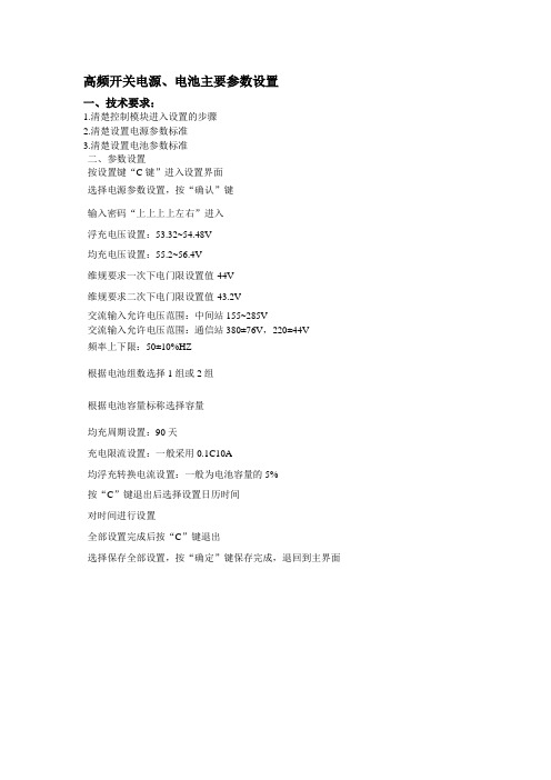
高频开关电源、电池主要参数设置
一、技术要求:
1.清楚控制模块进入设置的步骤
2.清楚设置电源参数标准
3.清楚设置电池参数标准
二、参数设置
按设置键“C键”进入设置界面
选择电源参数设置,按“确认”键
输入密码“上上上上左右”进入
浮充电压设置:53.32~54.48V
均充电压设置:55.2~56.4V
维规要求一次下电门限设置值-44V
维规要求二次下电门限设置值-43.2V
交流输入允许电压范围:中间站155~285V
交流输入允许电压范围:通信站380±76V,220±44V
频率上下限:50±10%HZ
根据电池组数选择1组或2组
根据电池容量标称选择容量
均充周期设置:90天
充电限流设置:一般采用0.1C10A
均浮充转换电流设置:一般为电池容量的5%
按“C”键退出后选择设置日历时间
对时间进行设置
全部设置完成后按“C”键退出
选择保存全部设置,按“确定”键保存完成,退回到主界面。
基站开关电源基本参数设置

-------高压告警56~59V(57.5)
-------低压告警44~50V(44)(二次下电)
-------交流高压221~330V(290)
-------交流低压110~219V(154)
-------电池过温20~50℃(40)
基本参数设置
-------浮充电压(53.5-54V)2.23~2.25V/只设定
基站开关电源基本参数设置
一、设置标准
开关电源:通常-48V高频开关电源对阀控蓄电池组的浮充电压设置为(53.5V-54V),均充电压设置为56.4V,均充限流为0.1C (A),均充时间为10小时,均充周期为3个月,温度补偿系数设为3mv/℃/cell。开关电源的一次下电保护电压设置为46V,二次下电保护电压设置为44V。电池容量按实际标称容量设置。
-------电池容量设定-------电池容量300~1000AH(据实际设置)
-------电池组数2
感器,取消温度补偿。
B、更换开关电源监控单元或电池组,必须重新设置参数。
C、其他参数采用厂家默认参数设置。
二、设置说明
充电电压设置
a、浮充设置。浮充电压在25℃环境温度下,一般按2.23~2.25V/只设定,通常取低限设置有利于电池的使用寿命,(以电池厂家说明书规定设置浮充电压为准),浮充温度补偿系数通常取3mV/℃/只。
b、均充设置。均衡充电电压一般在2.30~2.35V/只/25℃,均充时间为12~8h。通常均衡充电电压设为为2.35V/只,均充时间为10h。(可根据蓄电池的不同按产品说明具体执行)
蓄电池的放充电
放电是为了检查电池容量是否正常,一般采用10小时率放电,有条件的可用假负载放电;从维护方便考虑,可直接用负载进行放电,即拉掉市电,用电池组供电,考虑到安全性,放电深度控制在30~50%为宜。当然,有条件可放电更深一些,容易暴露电池潜在的问题。并且每小时检测一次单体电池电压,通过计算放出电池容量,对照附表电压值,判断电池是否正常。根据测记的数据做出放电曲线,留作以后再次测试时比较。电池组放电结束后,立即转入均衡充电,充电限流不大于0.2C (A),通常采用0.1C (A)为宜。(在容量测试期间通信安全都会受到一定的威胁。因此在做容量试验时要防止市电停电,备用发电机组应处于良好状态)
电池参数设置

电池参数设置————————————————————————————————作者:————————————————————————————————日期:DescriptionThe Battery block implements a generic dynamic model parameterized to represent most popular types of rechargeable batteries.The equivalent circuit of the battery is shown below:Lead-Acid ModelDischarge model (i* > 0)f1(it,i∗,i,Exp)=E0−K⋅QQ−it⋅i∗−K⋅QQ−it⋅it+Laplace−1(Exp(s)Sel(s)⋅0).Charge Model (i* < 0)f2(it,i∗,i,Exp)=E0−K⋅Qit+0.1⋅Q⋅i∗−K⋅QQ−it⋅it+Laplace−1(Exp(s)Sel(s)⋅1s).Lithium-Ion ModelDischarge Model (i* > 0)f1(it,i∗,i)=E0−K⋅QQ−it⋅i∗−K⋅QQ−it⋅it+A⋅exp(−B⋅it).Charge Model (i* < 0)f2(it,i∗,i)=E0−K⋅Qit+0.1⋅Q⋅i∗−K⋅QQ−it⋅it+A⋅exp(−B⋅it).Nickel-Cadmium and Nickel-Metal-Hydride ModelDischarge Model (i* > 0)f1(it,i∗,i,Exp)=E0−K⋅QQ−it⋅i∗−K⋅QQ−it⋅it+Laplace−1(Exp(s)Sel(s)⋅0).Charge Model (i*< 0)f2(it,i∗,i,Exp)=E0−K⋅Q↓↓it↓↓+0.1⋅Q⋅i∗−K⋅QQ−it⋅it+Laplace−1(Exp(s)Sel(s)⋅1s),where,E Batt = Nonlinear voltage (V)E0 = Constant voltage (V)Exp(s)= Exponential zone dynamics (V)Sel(s)= Represents the battery mode. Sel(s) = 0 during battery discharge, Sel(s) = 1 during battery charging.K = Polarization constant (Ah−1) or Polarization resistance (Ohms)i* = Low frequency current dynamics (A)i = Battery current (A)it = Extracted capacity (Ah)Q = Maximum battery capacity (Ah)A = Exponential voltage (V)B = Exponential capacity (Ah)−1The parameters of the equivalent circuit can be modified to represent a particular battery type, based on its discharge characteristics. A typical discharge curve is composed of three sections, as shown in the next figure:The first section represents the exponential voltage drop when the battery is charged. Depending on the battery type, this area is more or less wide. The second section represents the charge that can be extracted from the battery until the voltage drops below the battery nominal voltage. Finally, the third section represents the total discharge of the battery, when the voltage drops rapidly.When the battery current is negative, the battery will recharge following a charge characteristic as shown below:Note that the parameters of the model are deduced from discharge characteristics and assumed to be the same for charging.The Exp(s) transfer function represents the hysteresis phenomenon for the Lead-Acid, NiCD and NiMH batteries during charge and discharge cycles. The exponential voltage increases when battery is charging, no matter the SOC of the battery. When the battery is discharging, the exponential voltage decreases immediately:Dialog Box and ParametersParameters TabBattery typeProvides a set of predetermined charge behavior for four types of battery:•Lead-Acid•Lithium-Ion•Nickel-Cadmium•Nickel-Metal-HydrideNominal Voltage (V)The nominal voltage (Vnom) of the battery (volts). The nominal voltage represents the end of the linear zone of the discharge characteristics.Rated Capacity (Ah)The rated capacity (Qrated) of the battery in ampere-hour. The rated capacity is the minimum effective capacity of the battery.Initial State-Of-Charge (%)The initial State-Of-Charge (SOC) of the battery. 100% indicates a fully charged battery and 0% indicates an empty battery. This parameter is used as an initial condition for the simulation and does not affect the discharge curve (when the option Plot Discharge Characteristics is used). Use parameters based on Battery type and nominal valuesLoad the corresponding parameters in the entries of the dialog box, depending on the selected Battery type, the Nominal Voltage and the Rated Capacity.When a preset model is used, the detailed parameters cannot be modified. If you want to modify the discharge curve, select the desired battery type to load the default parameters, and then uncheck the Use parameters based on Battery type and nominal values checkbox to access the detailed parameters.Maximum Capacity (Ah)The maximum theoretical capacity (Q), when a discontinuity occurs in the battery voltage. This value is generally equal to 105% of the rated capacity.Fully charged Voltage (V)The fully charged voltage (Vfull), for a given discharge current. Note that the fully charged voltage is not the no-load voltage.Nominal Discharge Current (A)The nominal discharge current, for which the discharge curve has been measured. For example, a typical discharge current for a 1.5 Ah NiMH battery is 20% of the rated capacity: (0.2 * 1.5 Ah / 1h = 0.3A).Internal ResistanceThe internal resistance of the battery (ohms). When a preset model is used, a generic value is loaded, corresponding to 1% of the nominal power (nominal voltage * rated capacity of the battery). The resistance is supposed to be constant during the charge and the discharge cycles and does not vary with the amplitude of the current.Capacity (Ah) @ Nominal VoltageThe capacity (Qnom) extracted from the battery until the voltage drops under the nominal voltage. This value should be between Qexp and Qmax.Exponential zone [Voltage (V), Capacity (Ah)]The voltage (Vexp) and the capacity (Qexp) corresponding to the end of the exponential zone. The voltage should be between Vnom and Vfull. The capacity should be between 0 and Qnom.View Discharge Characteristics TabPlot Discharge CharacteristicsClick to plot a figure containing two graphs. The first graph represents the nominal discharge curve (at the Nominal Discharge Current) and the second graph represents the discharge curves at the specified discharge currents.Discharge currentAllows to specify different values of discharge current. The discharge characteristics for these currents are presented in the second part of the graph.UnitsChoose either Time or Ampere-hour as the x-axis for the plot.Battery Dynamics TabBattery response time (s)The response time of the battery (at 95% of the final value).This value represents the voltage dynamics and can be observed when a current step is applied:In this example, a battery response time of 30 secs is used.Extract Battery Parameters From Data SheetsThis section gives an example of detailed parameters extracted from the Panasonic NiMH-HHR650D battery data sheet:From the specification tables, we obtain the rated capacity and the internal resistance. The other detailed parameters are deduced from the Typical Discharge Characteristics plot:Parameter Value Rated capacity 6.5 Ah Internal Resistance 2 mΩNominal V oltage (a) 1.18 V Rated Capacity 6.5 Ah Maximum Capacity (b)7 Ah (5.38h Fully Charged voltage (c) 1.39 V Nominal Discharge Current (d) 1.3 A Capacity @ Nominal V oltage (a) 6.25 Ah Exponential V oltage (e) 1.28 V Exponential Capacity (e) 1.3 AhThese parameters are approximate and depend on the precision of the points obtained from the discharge curve. A tool, called ScanIt (provided by amsterCHEM,) can be used to extract values from data sheet curves.The parameters obtained from the data sheet are entered in the mask of the Battery block as in the following picture:The discharge curves (the dotted line curves in the following plots) obtained with these parameters are similar to the data sheet curves.Cells in Series and/or in ParallelTo model a series and/or parallel combination of cells based on the parameters of a single cell, the parameter transformation shown in the next figure can be used. The Nb_ser variable in mask below corresponds to the number of cells in series, and Nb_par corresponds to the number of cell in parallel:Block Inputs and OutputsmThe Simulink output of the block is a vector containing three signals. You can demultiplex thesesignals by using the Bus Selector block provided in the Simulink library.Signal DefinitionSOC The State-Of-Charge of the battery (between 0 and 100%). The SOC for a fully charged battery is 10 SOC=100(1−1Q Z t0i(t) dt).Current The Battery currentV oltage The Battery voltageModel ValidationExperimental validation of the model shown a maximum error of 5% (when SOC is between 10%and 100%) for charge (current between 0 and 2C) and discharge (current between 0 and 5C)dynamics.Model Assumptions•The internal resistance is supposed constant during the charge and the discharge cycles and doesn't vary with the amplitude of the current.•The parameters of the model are deduced from discharge characteristics and assumed tobe the same for charging.•The capacity of the battery doesn't change with the amplitude of current (No Peukert effect).•The model doesn't take the temperature into account.•The Self-Discharge of the battery is not represented. It can be represented by adding a large resistance in parallel with the battery terminals.•The battery has no memory effect.Limitations•The minimum no-load battery voltage is 0 volt and the maximum battery voltage is equal to 2*E0.•The minimum capacity of the battery is 0 Ah and the maximum capacity is Qmax. ExampleThe power_battery example illustrates a 200 volts, 6.5 Ah NiMH battery connected to a constant load of 50 A. The DC machine is connected in parallel with the load and operates at no load torque. When the State-Of-Charge (SOC) of the battery goes under 0.4 (40%), a negative load torque of 200 Nm is applied to the machine so it acts as a generator to recharge the battery. When the SOC goes over 80%, the load torque is removed so only the battery supplies the 50 amps load.The simulation produces the followings results:The battery is discharged by the constant DC load of 50 A. When the SOC drops under 0.4, a mechanical torque of −200 Nm is applied so the machine acts as a generator and provides a current of 100 amps. Hence, 50 amps goes to the load and 50 amps goes to recharge the battery. When the SOC goes over 0.8, the mechanical torque is removed and the machine operates freely. And then the cycle restarts.References[1] Tremblay, O., Dessaint, L.-A. "Experimental Validation of a Battery Dynamic Model for EV Applications." World Electric Vehicle Journal. V ol. 3 - ISSN 2032-6653 - © 2009 A VERE, EVS24 Stavanger, Norway, May 13 - 16, 2009.Introduced in R2008a。
锂电池保护芯片参数

锂电池保护芯片参数
保护芯片是用于锂电池管理的重要组件,其作用是监控电池的电压、电流和温度等参数,并根据需要进行保护或调节。
下面,我将介绍常见的锂电池保护芯片参数及其功能。
1. 过充保护电压
过充保护电压指电池电压达到一定值时,保护芯片会控制充电器停止充电,避免电池过充。
一般情况下,过充保护电压设置在4.2V左右,但不同的电池类型和应用场景对其要求不同。
2. 欠压保护电压
欠压保护电压是指当电池电压降至一定程度时,保护芯片会控制负载停止工作,以避免电池欠压。
一般情况下,欠压保护电压设置在2.5V 至3.0V之间,但同样存在不同的设置要求。
3. 过流保护电流
过流保护电流是指当电池充电或放电过程中电流超过设定值时,保护芯片会立即停止充电或放电,并进行相应的保护处理。
一般情况下,
过流保护电流设置在1C至3C之间,C值是指电池的额定容量。
4. 短路保护电流
短路保护电流是指当电池的正极和负极短路时,保护芯片会立即停止充电或放电,并进行相应的保护处理。
短路保护电流的设置与过流保护电流的设置类似,一般在1C至3C之间。
5. 温度保护范围
温度保护范围是指保护芯片能够探测的电池温度范围,一旦电池温度超出设定范围,保护芯片会采取相应的保护措施。
一般情况下,温度保护范围设置在-20℃至60℃之间。
总体来说,锂电池保护芯片的参数设置需要根据具体的电池型号、应用场景和使用要求进行调整。
只有在合理的参数设置下,锂电池保护芯片才能够发挥最佳的保护作用,并确保电池的安全和稳定运行。
apcups电池参数设置步骤
apcups电池参数设置步骤
嘿,朋友们!今天咱就来讲讲这个 APCUPS 电池参数设置步骤。
这可不像煮个泡面那么简单哦,得认真对待呢!
你想想,这电池参数设置就好比给汽车调发动机,调得好那就是一
路顺畅,调不好可就麻烦啦!那怎么个设置法呢?
首先,你得找到那个设置的入口,就像找宝藏的入口一样。
这可得
有点耐心,别着急,慢慢找。
然后呢,进入到那个神秘的设置界面,
就好像进入了一个奇妙的数字世界。
在这里面啊,各种参数就像一群小精灵,等着你去驯服它们。
比如
说电压啦、电流啦,这些可都得设置得恰到好处。
这就像做菜放盐一样,多了咸,少了淡,得掌握好那个度。
比如说电压设置吧,你可不能随便乱来。
太高了,电池可能受不了,就像人吃多了会撑一样;太低了呢,又发挥不出它应有的作用,那不
就白瞎了嘛!所以啊,得根据实际情况,小心翼翼地调整。
还有电流设置也是同样重要呢!电流就像是电池的动力源泉,设置
得合适,它就能活力满满地工作;设置不合适,那它可能就会“闹脾气”哦!
在设置的过程中,你可得时刻保持警惕,就像走钢丝一样,稍不注
意可能就会掉下去。
每一个参数的调整都要谨慎再谨慎,可不能马虎哟!
哎呀,说了这么多,其实就是要告诉大家,APCUPS 电池参数设置
可不能小瞧了。
这就像一场战斗,你得有策略、有技巧地去应对。
总之呢,设置好了这些参数,你的 APCUPS 就能更好地为你服务啦,就像一个忠诚的卫士,时刻守护着你的设备。
怎么样,是不是觉得很
有意思呀?别犹豫啦,赶紧去试试吧!。
17串三元锂电池参数设置方法

17串三元锂电池参数设置方法
嘿,朋友们!今天咱就来讲讲这 17 串三元锂电池参数设置方法,这可太重要啦!
你想想看啊,就好比你要去参加一场比赛,装备不调好怎么能行?这参数设置不恰当,电池可不就没法发挥最佳性能嘛!
首先呢,咱得搞清楚电池的容量,就跟咱人得知道自己饭量多大一个道理呀!要是容量设低了,那岂不是关键时刻掉链子,电器用着用着就没电啦,多闹心!
然后呢,电压也得设置准咯!这就好比给电池安上合适的“动力心脏”,要是电压不对,那可就像汽车跑不起来一样啦。
比如说,你把电压设高了,那电池会不会“压力山大”,出问题呀?
电流的设置也不能马虎呀!太大会怎样?哎呀,那不就跟水管水压太大容易爆管一个样嘛!太小呢,又带不动那些用电设备,急死人啦!
咱可不能小瞧这参数设置,这就像给电池打造了一个完美的小世界。
咱得细心、耐心地一点点调好,让它为我们好好服务!这 17 串三元锂电池参数得这么设,才能让它发挥出真正的威力呀!
总之呢,好好设置这 17 串三元锂电池参数,才能让它成为我们的得力小助手哦!。
电化学站电池倍率测试工步设置
电化学站电池倍率测试工步设置电化学站电池倍率测试工步设置一、前言在电池领域,倍率是一个非常重要的指标,它代表着电池的放电和充电速度。
电池倍率测试工步设置的合理性直接影响着电池的性能评估和应用。
本文将针对电化学站电池倍率测试工步设置进行深入探讨,帮助读者更好地理解和应用这一概念。
二、电池倍率测试工步设置的重要性电池的倍率是指充放电电流与电池额定容量之比。
在实际应用中,电池需要根据不同的需求来充放电,而不同的应用场景可能对电池的倍率有着不同的要求。
电池的倍率测试工步设置是十分重要的。
合理的测试工步设置可以准确评估电池的性能,为其在不同场景下的应用提供参考依据。
三、电池倍率测试工步设置的参数1. 充放电电流:充放电电流是影响电池倍率的关键参数,它直接影响着电池的充放电速率。
在进行倍率测试时,需要根据实际应用情况,设置合适的充放电电流值。
2. 温度控制:温度对电池性能有着重要影响,因此在倍率测试中需要对温度进行控制,以保证测试结果的准确性。
3. 循环次数:倍率测试工步设置中,循环次数也是一个需要考虑的因素。
通过多次循环测试,可以更全面地评估电池的性能,但是过多的循环次数也会增加测试时间和成本。
四、电池倍率测试工步设置的实际应用在实际应用中,电池倍率测试工步设置需要根据不同的电池类型和应用场景来进行调整。
如果是用于动力电池系统的电池,通常需要进行高倍率测试,以确保电池在高功率工况下的可靠性。
而对于储能电池系统来说,可能更关注低倍率下的循环稳定性。
五、结语通过本文的介绍,相信读者对电化学站电池倍率测试工步设置有了更深入的理解。
在实际应用中,合理的倍率测试工步设置将对电池的性能评估和应用提供重要参考。
期待在未来的发展中,电池倍率测试工步设置能够更加智能化和精准化,为电池技术的发展提供更强有力的支持。
个人观点:电池倍率测试工步设置是电池研发和应用中的关键环节之一。
随着电动汽车、储能系统等领域的迅速发展,对电池倍率的要求也越来越高。
电池基本参数说明.doc

电池基本参数说明.doc
1、容量:指电池贮存和供给能量的量,通常按仓值来衡量,计算公式(电容)
VAh=Tc×If
2、电压:指电池提供能量的电压,常用单位是伏特,即 V.
3、荷电:指电池内电荷的度,也叫交流部分,单位(电荷)C.
5、放电:衡量电池在放电过程中电压的下降,即放电压滞,此参数一般表示在额定
负载下降到额定电压时电池的放电时间,单位为小时。
6、内阻:表示电动机内部电池对能量输出有多少阻力,内阻影响电池的发电量和健
康状况,单位是欧姆,可以用mΩ来表示。
7、温度:指电池在放电过程中的温度,也是电池性能好坏的重要参数决定因素之一,也是放电效率的重要影响因素,通常用摄氏度来表示,可用℃来表示。
全志电池参数配置说明

1全志关于PMU电源配置的说明文档1.1 [pmu_para]pmu_used=xx 1 Pmu使能标志(xx=1 or 0),0:不使用,1:使用1pmu_twi_addr=xx 0x34 Pmu 设备地址pmu_twi_id=xx 0 Pmu挂载的i2c控制器号,0:twi0,1:twi1,2:twi2pmu_irq_id=xx 0 Pmu 中断号,0:NMI,1:1号中断2:2号中断……pmu_battery_rdc=xx 150 电池内阻,mΩ,根据实际测试填写pmu_battery_cap=xx 4000 电池容量,mAh,根据实际测试填写pmu_init_chgcur=xx 300 设置开机充电电流,mA,300/400/500/600/700/800/900/1000/1100/1200/1300/1400/1500/1600/1700/1800pmu_earlysuspend_chgcur=xx 500 设置关屏充电电流,mA,300/400/500/600/700/800/900/1000/1100/1200/1300/1400/1500/1600/1700/1800pmu_suspend_chgcur=xx 1000 设置休眠充电电流,mA,300/400/500/600/700/800/900/1000/1100/1200/1300/1400/1500/1600/1700/1800pmu_resume_chgcur=xx 300 设置唤醒充电电流,mA,300/400/500/600/700/800/900/1000/1100/1200/1300/1400/1500/1600/1700/1800pmu_shutdown_chgcur=xx 1300 设置关机充电电流,mA300/400/500/600/700/800/900/1000/1100/1200/1300/1400/1500/1600/1700/1800pmu_init_chgvol=xx 4200 设置充电目标电压,mV,4100/4150/4200/4360pmu_init_chgend_rate=xx 15 设置结束充电电流的比率,%,10,15 pmu_init_chg_enabled=xx 1 设置充电功能,0:关闭,1:打开pmu_init_adc_freq=xx 100 设置adc采样率,Hz,25/50/100/200 pmu_init_adc_freqc=xx 100 设置库仑计采样率,Hz,25/50/100/200pmu_init_chg_pretime=xx 50 设置预充电超时时间,min,40/50/60/70 pmu_init_chg_csttime=xx 720 设置恒流充电超时时间,min,360/480/600/720pmu_bat_para1=xx 设置空载电池电压对应的百分比,%,具体请看《电池参数测试操作指南》文档pmu_bat_para2=xx 设置空载电池电压对应的百分比,%,具体请看《电池参数测试操作指南》文档pmu_bat_para3=xx 设置空载电池电压对应的百分比,%,具体请看《电池参数测试操作指南》文档pmu_bat_para4=xx 设置空载电池电压对应的百分比,%,具体请看《电池参数测试操作指南》文档pmu_bat_para5=xx 设置空载电池电压对应的百分比,%,具体请看《电池参数测试操作指南》文档pmu_bat_para6=xx 设置空载电池电压对应的百分比,%,具体请看《电池参数测试操作指南》文档pmu_bat_para7=xx 设置空载电池电压对应的百分比,%,具体请看《电池参数测试操作指南》文档pmu_bat_para8=xx 设置空载电池电压对应的百分比,%,具体请看《电池参数测试操作指南》文档pmu_bat_para9=xx 设置空载电池电压对应的百分比,%,具体请看《电池参数测试操作指南》文档pmu_bat_para10=xx 设置空载电池电压对应的百分比,%,具体请看《电池参数测试操作指南》文档pmu_bat_para11=xx 设置空载电池电压对应的百分比,%,具体请看《电池参数测试操作指南》文档pmu_bat_para12=xx 设置空载电池电压对应的百分比,%,具体请看《电池参数测试操作指南》文档pmu_bat_para13=xx 设置空载电池电压对应的百分比,%,具体请看《电池参数测试操作指南》文档pmu_bat_para14=xx 设置空载电池电压对应的百分比,%,具体请看《电池参数测试操作指南》文档pmu_bat_para15=xx 设置空载电池电压对应的百分比,%,具体请看《电池参数测试操作指南》文档pmu_bat_para16=xx 设置空载电池电压对应的百分比,%,具体请看《电池参数测试操作指南》文档,建议此处固定为100pmu_usbvol_limit=xx 1 设置usb限压功能,0:关闭,1:打开pmu_usbvol=xx 4400 设置usb限压电压,mV,4000/4100/4200/4300/4400/4500/4600/4700 pmu_usbcur_limit=xx 0 设置usb限流功能,0:关闭,1:打开pmu_usbcur=xx 500 设置usb限流电流,mA,100/500/900 pmu_pwroff_vol=xx 3300 设置启动时的硬件保护电压,mV,2600/2700/2800/2900/3000/3100/3200/3300pmu_pwron_vol=xx 2900 设置开机状态下的硬件保护电压,mV,2600/2700/2800/2900/3000/3100/3200/3300 pmu_pekoff_time=xx 6000 设置硬件关机时长,ms,4000/6000/8000/10000pmu_pekoff_en=xx 1 设置硬件关机功能,0:关闭,1:打开pmu_peklong_time=xx 1500 设置长按键中断时间,ms,1000/1500/2000/2500pmu_pekon_time=xx 2000 设置开机时间,ms,128/1000/2000/3000 pmu_pwrok_time=xx 64 设置电源启动完成后pwrok信号延时,ms,8/64pmu_pwrnoe_time=xx 2000 设置n_oe由低变高后关机延迟时间,ms,128/1000/2000/3000pmu_intotp_en=xx 1 设置过温关机功能,0:关闭,1:打开pmu_used2=xx 专门为佳的美案子做的一个设置,配合pmu_adpdet~ pmu_shutdown_chgcur2,打开1,关闭0pmu_adpdet=xx 佳的美案子的设置,火牛探测口设置,具体参看上面gpio的配置pmu_init_chgcur2=xx 佳的美案子的设置,插入火牛时,开机充电电流设置,同pmu_init_chgcurpmu_earlysuspend_chgcur2=xx 佳的美案子的设置,插入火牛时,关屏充电电流设置,同pmu_earlysuspend_chgcur pmu_suspend_chgcur2=xx 佳的美案子的设置,插入火牛时,休眠充电电流设置,同pmu_suspend_chgcur pmu_resume_chgcur2=xx 佳的美案子的设置,插入火牛时,唤醒充电电流设置,同pmu_resume_chgcurpmu_shutdown_chgcur2=xx 佳的美案子的设置,插入火牛时,关机充电电流设置,同pmu_shutdown_chgcur pmu_suspendpwroff_vol=xx 3400 休眠关机电压设置,mV,2867~4200,6mV一档pmu_batdeten=xx 1 电池探测功能设置,0:关闭,1:打开注意:pmu_used2~ pmu_shutdown_chgcur2之间的参数是为佳的美案子专门做的接口,对其他案子可以删掉。
电池参数设置方法

Smart-UPS长延时机型电池参数设置方法第一步,将UPS串口用APC专用原配RS-232通讯线与计算机串口连接(该通讯线的APC型号为940-0024C或940-1524C,这个型号印在串口的母头一端)。
第二步,进入Windows 98,NT,2000,XP操作系统附件中的Hyperterminal(超级终端),选中运行该程序,如图1所示。
启动超级终端,名称和图标随意选择,如图2所示,之后单击“OK”。
连接方式选择串口,如图3所示。
如果有不止一个串口显示的话,请确认插在计算机背面的实际是哪个串口后,再进行选择,然后单击“OK”。
第三步,修改配置如图4,之后单击“OK”,进入下面的界面。
此时,键入大写"Y",即同时按"SHIFT"和"y",等待屏幕上显示"SM"表示通讯已建立。
再键入">",屏幕上会显示当前联接电池数(通常第一次设置前会显示000),键入"+" (加号),每键入一次,即按"shift"加"+",电池参数加一,键入"-" (减号),电池参数减一。
修改完毕后,键入">"(大于号)确定。
详细过程见上图,这是一个把电池参数设置为4的实例。
电池参数如何确定:对于型号以SU或SUA开头的互动式UPS:电池参数=(每节电池的安时数X外接电池总个数)/ 68如果得出小数,四舍五入即可对于型号以SURT开头的在线双变换式UPS:1000VA和2000VA的UPS,电池参数=(每节电池的安时数X外接电池总个数)/ 723000VA和5000VA的UPS,电池参数=(每节电池的安时数X外接电池总个数)/ 807500VA和10000VA的UPS,电池参数=(每节电池的安时数X外接电池总个数)/ 160如果得出小数,四舍五入即可。
电池使用中的额定参数

1、电池使用中的额定参数
1、容量C:容量是指在规定的放电制度下(放电电流、放电时间、放电终止电压、温度、电解液密度及电解液高度)电池所放出来的电量。
2、电压U:电池单体的电压为标明的数值
3、电流I:电池的电流是指在容量下工作时的电流值I=C/T
4、放电时间T:放电时间与容量对应的放电时间
5、GFM中G代表固定式F代表阀控式M代表密封
二、故障处理
电池常见故障和处理方法:
序号故障原因处理方法
1 漏液电池外壳变形,温度过高,浮
充电压过高电池极性密封不
严
与供应商联系及时更换处理
2 浮充电压不均匀电池内阻不均匀均衡充电12~24H,均充电压
参照电池说明
3 单体浮充电压偏低电池内部微短路等均衡充电12~24H,仍不能排
除故障的请更换电池
4 容量不足A、电池欠充
B、失水严重,内部干枯A、均衡充电12~24H,仍不能排除故障的请更换电池B、补加点解呀
5 电池极性或外壳温
度过高螺丝松动,浮充电压过高等检查螺丝,检查充电机和充
电方法
6 电池浮充电压忽高
忽低
螺丝松动拧紧螺丝
7 电池组接地电池盖规程或电解液残留物
导电清洗电池
电池组与地面加绝缘胶垫。
- 1、下载文档前请自行甄别文档内容的完整性,平台不提供额外的编辑、内容补充、找答案等附加服务。
- 2、"仅部分预览"的文档,不可在线预览部分如存在完整性等问题,可反馈申请退款(可完整预览的文档不适用该条件!)。
- 3、如文档侵犯您的权益,请联系客服反馈,我们会尽快为您处理(人工客服工作时间:9:00-18:30)。
DescriptionThe Battery block implements a generic dynamic model parameterized to represent most popular types of rechargeable batteries.The equivalent circuit of the battery is shown below:Lead-Acid ModelDischarge model (i* > 0)f1(it,i∗,i,Exp)=E0−K⋅QQ−it⋅i∗−K⋅QQ−it⋅it+Laplace−1(Exp(s)Sel(s)⋅0).Charge Model (i* < 0)f2(it,i∗,i,Exp)=E0−K⋅Qit+0.1⋅Q⋅i∗−K⋅QQ−it⋅it+Laplace−1(Exp(s)Sel(s)⋅1s).Lithium-Ion ModelDischarge Model (i* > 0)f1(it,i∗,i)=E0−K⋅QQ−it⋅i∗−K⋅QQ−it⋅it+A⋅exp(−B⋅it).Charge Model (i* < 0)f2(it,i∗,i)=E0−K⋅Qit+0.1⋅Q⋅i∗−K⋅QQ−it⋅it+A⋅exp(−B⋅it).Nickel-Cadmium and Nickel-Metal-Hydride ModelDischarge Model (i* > 0)f1(it,i∗,i,Exp)=E0−K⋅QQ−it⋅i∗−K⋅QQ−it⋅it+Laplace−1(Exp(s)Sel(s)⋅0).Charge Model (i*< 0)f2(it,i∗,i,Exp)=E0−K⋅Q↓↓it↓↓+0.1⋅Q⋅i∗−K⋅QQ−it⋅it+Laplace−1(Exp(s)Sel(s)⋅1s),where,E Batt = Nonlinear voltage (V)E0 = Constant voltage (V)Exp(s)= Exponential zone dynamics (V)Sel(s)= Represents the battery mode. Sel(s) = 0 during battery discharge, Sel(s) = 1 during battery charging.K = Polarization constant (Ah−1) or Polarization resistance (Ohms)i* = Low frequency current dynamics (A)i = Battery current (A)it = Extracted capacity (Ah)Q = Maximum battery capacity (Ah)A = Exponential voltage (V)B = Exponential capacity (Ah)−1The parameters of the equivalent circuit can be modified to represent a particular battery type, based on its discharge characteristics. A typical discharge curve is composed of three sections, as shown in the next figure:The first section represents the exponential voltage drop when the battery is charged. Depending on the battery type, this area is more or less wide. The second section represents the charge that can be extracted from the battery until the voltage drops below the battery nominal voltage. Finally, the third section represents the total discharge of the battery, when the voltage drops rapidly.When the battery current is negative, the battery will recharge following a charge characteristic as shown below:Note that the parameters of the model are deduced from discharge characteristics and assumed to be the same for charging.The Exp(s) transfer function represents the hysteresis phenomenon for the Lead-Acid, NiCD and NiMH batteries during charge and discharge cycles. The exponential voltage increases when battery is charging, no matter the SOC of the battery. When the battery is discharging, the exponential voltage decreases immediately:Dialog Box and ParametersParameters TabBattery typeProvides a set of predetermined charge behavior for four types of battery:•Lead-Acid•Lithium-Ion•Nickel-Cadmium•Nickel-Metal-HydrideNominal Voltage (V)The nominal voltage (Vnom) of the battery (volts). The nominal voltage represents the end of the linear zone of the discharge characteristics.Rated Capacity (Ah)The rated capacity (Qrated) of the battery in ampere-hour. The rated capacity is the minimum effective capacity of the battery.Initial State-Of-Charge (%)The initial State-Of-Charge (SOC) of the battery. 100% indicates a fully charged battery and 0% indicates an empty battery. This parameter is used as an initial condition for the simulation and does not affect the discharge curve (when the option Plot Discharge Characteristics is used). Use parameters based on Battery type and nominal valuesLoad the corresponding parameters in the entries of the dialog box, depending on the selected Battery type, the Nominal Voltage and the Rated Capacity.When a preset model is used, the detailed parameters cannot be modified. If you want to modify the discharge curve, select the desired battery type to load the default parameters, and then uncheck the Use parameters based on Battery type and nominal values checkbox to access the detailed parameters.Maximum Capacity (Ah)The maximum theoretical capacity (Q), when a discontinuity occurs in the battery voltage. This value is generally equal to 105% of the rated capacity.Fully charged Voltage (V)The fully charged voltage (Vfull), for a given discharge current. Note that the fully charged voltage is not the no-load voltage.Nominal Discharge Current (A)The nominal discharge current, for which the discharge curve has been measured. For example, a typical discharge current for a 1.5 Ah NiMH battery is 20% of the rated capacity: (0.2 * 1.5 Ah / 1h = 0.3A).Internal ResistanceThe internal resistance of the battery (ohms). When a preset model is used, a generic value is loaded, corresponding to 1% of the nominal power (nominal voltage * rated capacity of the battery). The resistance is supposed to be constant during the charge and the discharge cycles and does not vary with the amplitude of the current.Capacity (Ah) @ Nominal VoltageThe capacity (Qnom) extracted from the battery until the voltage drops under the nominal voltage. This value should be between Qexp and Qmax.Exponential zone [Voltage (V), Capacity (Ah)]The voltage (Vexp) and the capacity (Qexp) corresponding to the end of the exponential zone. The voltage should be between Vnom and Vfull. The capacity should be between 0 and Qnom.View Discharge Characteristics TabPlot Discharge CharacteristicsClick to plot a figure containing two graphs. The first graph represents the nominal discharge curve (at the Nominal Discharge Current) and the second graph represents the discharge curves at the specified discharge currents.Discharge currentAllows to specify different values of discharge current. The discharge characteristics for these currents are presented in the second part of the graph.UnitsChoose either Time or Ampere-hour as the x-axis for the plot.Battery Dynamics TabBattery response time (s)The response time of the battery (at 95% of the final value).This value represents the voltage dynamics and can be observed when a current step is applied:In this example, a battery response time of 30 secs is used.Extract Battery Parameters From Data SheetsThis section gives an example of detailed parameters extracted from the Panasonic NiMH-HHR650D battery data sheet:From the specification tables, we obtain the rated capacity and the internal resistance. The other detailed parameters are deduced from the Typical Discharge Characteristics plot:Parameter Value Rated capacity 6.5 Ah Internal Resistance 2 mΩNominal V oltage (a) 1.18 V Rated Capacity 6.5 Ah Maximum Capacity (b)7 Ah (5.38h Fully Charged voltage (c) 1.39 V Nominal Discharge Current (d) 1.3 A Capacity @ Nominal V oltage (a) 6.25 Ah Exponential V oltage (e) 1.28 V Exponential Capacity (e) 1.3 AhThese parameters are approximate and depend on the precision of the points obtained from the discharge curve. A tool, called ScanIt (provided by amsterCHEM,) can be used to extract values from data sheet curves.The parameters obtained from the data sheet are entered in the mask of the Battery block as in the following picture:are similar to the data sheet curves.Cells in Series and/or in ParallelTo model a series and/or parallel combination of cells based on the parameters of a single cell, the parameter transformation shown in the next figure can be used. The Nb_ser variable in mask below corresponds to the number of cells in series, and Nb_par corresponds to the number of cell in parallel:Block Inputs and OutputsmThe Simulink output of the block is a vector containing three signals. You can demultiplex theseModel ValidationExperimental validation of the model shown a maximum error of 5% (when SOC is between 10% and 100%) for charge (current between 0 and 2C) and discharge (current between 0 and 5C) dynamics.Model Assumptions•The internal resistance is supposed constant during the charge and the discharge cycles and doesn't vary with the amplitude of the current.•The parameters of the model are deduced from discharge characteristics and assumed tobe the same for charging.•The capacity of the battery doesn't change with the amplitude of current (No Peukert effect).•The model doesn't take the temperature into account.•The Self-Discharge of the battery is not represented. It can be represented by adding a large resistance in parallel with the battery terminals.•The battery has no memory effect.Limitations•The minimum no-load battery voltage is 0 volt and the maximum battery voltage is equal to 2*E0.•The minimum capacity of the battery is 0 Ah and the maximum capacity is Qmax. ExampleThe power_battery example illustrates a 200 volts, 6.5 Ah NiMH battery connected to a constant load of 50 A. The DC machine is connected in parallel with the load and operates at no load torque. When the State-Of-Charge (SOC) of the battery goes under 0.4 (40%), a negative load torque of 200 Nm is applied to the machine so it acts as a generator to recharge the battery. When the SOC goes over 80%, the load torque is removed so only the battery supplies the 50 amps load.The simulation produces the followings results:The battery is discharged by the constant DC load of 50 A. When the SOC drops under 0.4, a mechanical torque of −200 Nm is applied so the machine acts as a generator and provides a current of 100 amps. Hence, 50 amps goes to the load and 50 amps goes to recharge the battery. When the SOC goes over 0.8, the mechanical torque is removed and the machine operates freely. And then the cycle restarts.References[1] Tremblay, O., Dessaint, L.-A. "Experimental Validation of a Battery Dynamic Model for EV Applications." World Electric Vehicle Journal. V ol. 3 - ISSN 2032-6653 - © 2009 A VERE, EVS24 Stavanger, Norway, May 13 - 16, 2009.Introduced in R2008a。
