2835单晶0.2W规格书(22-24LM)
SMD2835灯珠规格书

不良数量 0/50 0/50 0/50 0/50 0/50 0/50 0/50 0/50 0/50
注释 1.所有尺寸单位为毫米。 2.如果无其它注明,公差范围通常采用±0.1 毫米。
建议焊盘尺寸
8
QQ--250884504
8.料盘结构和包装
包装标签
数量
流明值
BIN 区 正向电压
项目 盘 盒 箱
10
QQ--250884504
10.使用注意事项 储存 (1) 打开包装前 在温度不超过 40℃及湿度不超过 90%RH 条件下,LED 可以保存一年,在储存的时候, 建议采用带干燥剂的防潮袋的包装方式。 (2)打开包装后 LED 需要储存在<=40℃&<=60%RH 相对湿度的条件下,我们强烈建议您从打开包装到 完成贴片整个过程在一个星期内完成。 如果有未使用完的剩余 LED,我们建议重新使用出厂时的防潮剂,并且需要重新密封。 如果干燥剂过期了,请将 LED 放在 70℃烤箱烘烤 12 小时。 LED 电极和引线框架是由表面镀了银的铜合金构成,镀银层会受到来自周围环境的破坏, 请把 LED 远离那种会腐蚀 LED 电极镀银层的环境,LED 电极被腐蚀后,会降低它的焊接 能力和光电参数。 请避免 LED 使用在温度快速变化的环境中,尤其是会发生冷凝的高湿环境中。
CIE-Y 0.4085 0.4057 0.4153 0.4181
Rank
30C03 (2900-3100K)
CIE-X 0.4386 0.4494 0.4554 0.4443
CIE-Y
Rank
CIE-X
0.3818
0.3822
0.3762
40C03 0.3920
0.3888 (3900-4100K) 0.3974
2835灯珠光效流明误差值标准

2835灯珠光效流明误差值标准序今天,我们要探讨的主题是2835灯珠光效流明误差值标准。
作为LED照明行业中的一个重要参数,流明误差值标准对LED产品的质量和使用效果有着重要影响。
在本文中,我们将从不同角度对2835灯珠光效流明误差值标准进行全面评估,并探讨其在LED照明行业中的重要性和应用。
一、2835灯珠光效流明误差值标准的定义2835灯珠是LED照明产品中常用的一种灯珠规格,其光效流明误差值标准是衡量LED产品光效一致性的重要参数。
光效流明是指LED灯具单位功率所发出的光通量,而误差值标准则代表了LED产品在生产过程中的光效一致性。
通常情况下,流明误差值越小,LED产品的光效一致性越高,质量也越稳定可靠。
2835灯珠光效流明误差值标准的设定对于LED产品的质量控制和性能表现具有重要意义。
二、2835灯珠光效流明误差值标准的重要性在LED照明行业中,产品的光效一致性是保证照明效果和质量稳定的关键。
而2835灯珠光效流明误差值标准的设定可以有效地衡量LED 产品的光效一致性,并对产品的质量进行评估和控制。
通过严格的误差值标准,LED制造商能够确保其产品的光效稳定性和一致性,从而提高产品的市场竞争力和用户满意度。
标准化的流明误差值也有利于LED行业的发展,促进产品技术的进步和行业标准的统一。
三、2835灯珠光效流明误差值标准的应用在LED产品的生产和质量控制过程中,2835灯珠光效流明误差值标准被广泛应用于不同环节。
制造商可以根据误差值标准对LED芯片和灯珠进行筛选和分类,确保产品的光效一致性和质量稳定。
误差值标准也可以作为LED产品质量检测的重要依据,帮助制造商进行产品质量控制和改进。
消费者在选购LED产品时,也可以通过关注产品的流明误差值来判断产品的性能和质量,从而选择更加满意的产品。
总结回顾2835灯珠光效流明误差值标准作为LED照明行业中的重要参数,对于产品的质量控制和性能表现具有重要意义。
2835贴片规格书

中之光电科技有限公司ZT2835W0M1-****(0.2W)规格书2.8mm Medium Power SMT Hyper White Top LED2.8 mm 中功率贴片反射盖灌注型超亮发光二极管Features 特征• Package Size :2.8 (L) ×3.5(W) ×0.8 (T) mm封装尺寸: 2.8 (长) ×3.5 (宽) ×0.8 (厚) mm • Silicone Packed采用硅胶封装 •Super long life time超长寿命 •Anti UV 防紫外线•White colors are available in(1800K- 15000K) 可供白光(1800K- 15000K) •High CRI products高显色性产品•Wide viewing angle (2θ1/2=120°) 宽角度 (2θ1/2=120°)Applications 产品应用•Indoor lighting: Fluorescent lamp, tube •室内照明:日光灯管、灯条•Commercial illumination and displays: •商业照明显示:广告字、广告灯箱Advertising words, light box•LCD Backlighting •LCD 背光源 •Decorative lighting: light strip •装饰照明:柔性灯条 •Automotive interior auxiliary lighting•Other illumination and displays •其它照明和显示类OOF a Top View 顶视Side View 侧视OOPart No. Description产品型号说明Color Bin Limit色度代码;(at I F = 60 mA, T a = 25 O C )Color Bin色坐标常用BIN区(Common Bin)可选BIN区(Optional Bin)Typical Electro-Optical Characteristics Curves 典型光-电特性曲线图PACKAGE OUTLINE 外形尺寸 (Units: mm)Recommended Soldering 推荐焊接模式0.8Solder Pad一、PRECAUTONS IN USE LED/使用LED注意事项;LED Soldering condition/ LED焊接条件;1:烙铁焊接:烙铁最高30W尖端温度不超过300℃;焊接时不超过3秒;Manual soldering:iron Maximum 30W,iron bit temperature can not over 300 degree;soldering time should not be more than 3 seconds;Cleanout/清洗;当用化学品清洗LED胶体时须特别小心,因为有些化学品对胶体表面有损伤并引起褪色如三氯乙烯、丙酮,可用乙醇擦拭浸渍,时间在常温下不超过2分钟。
everlight 2835规格书
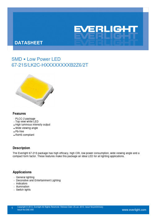
SMD Low Power LED67-21S/LK2C-HXXXXXXXXB2Z6/2TFeatures‧PLCC-2 packageTop view‧white LED˙High luminous intensity output˙Wide viewing angle˙Pb-free˙RoHS compliantDescriptionThe Everlight 67-21S package has high efficacy, high CRI, low power consumption, wide viewing angle and a compact form factor. These features make this package an ideal LED for all lighting applications.ApplicationsGeneral lighting‧Decorative and Entertainment Lighting‧Indicators‧Illumination‧Switch lights‧Product Number Explanation67–21S / L K 2 C – H XX XX XX XX XX / 2TBin Group of Forward VoltageBin Group of Max. Luminous FluxBin Group of Min. Luminous FluxMax. Color temperatureMin. Color temperatureBin Code of Color Rendering Index Table of Color Rendering IndexSymbol DescriptionM CRI(Min.) : 60N CRI(Min.) : 65L CRI(Min.) : 70Q CRI(Min.) : 75K CRI(Min.) : 80P CRI(Min.) : 85H CRI(Min.) : 90Note:Tolerance of Color Rendering Index: ±2Example:67-21S/LK2C-H3030M3N4B2Z6/2TCRI 70(Min.)CCT 3000KFlux 20~33lmV F 2.9~3.6VI F60mAMass Production ListProductCRIMin.(1)CCT(K)Φ(lm)Min. (2)Φ(lm)Max. (2)67-21S/LK2C-H2727M3N4B2Z6/2T 70 2700K 19 33 67-21S/LK2C-H3030M3N4B2Z6/2T 70 3000K 20 33 67-21S/LK2C-H4040M4N4B2Z6/2T 70 4000K 21 33 67-21S/LK2C-H5050M4N4B2Z6/2T 70 5000K 22 33 67-21S/LK2C-H5757M4N4B2Z6/2T 70 5700K 22 33 67-21S/LK2C-H6565M4N4B2Z6/2T 70 6500K 22 33Note:1. Tolerance of Color Rendering Index: ±22. Tolerance of Luminous flux: ±11%.Device Selection GuideChipMaterialsEmitted Color Resin ColorInGaNCool WhiteNeutral WhiteWarm WhiteWater ClearAbsolute Maximum Ratings (T Soldering=25℃)Parameter Symbol Rating Unit Forward Current I F75 mA Peak Forward Current (Duty 1/10 @10ms) I FP100 mA Power Dissipation P d270 mW Operating Temperature T opr-40 ~ +85 ℃Storage Temperature T stg-40 ~ +100 ℃Thermal Resistance (Junction / Soldering point) R th J-S50 ℃/W Junction Temperature T j125 ℃Soldering Temperature Tsol Reflow Soldering : 260 ℃ for 10 sec. Hand Soldering : 350 ℃ for 3 sec.Note:The products are sensitive to static electricity and must be carefully taken when handling productsElectro-Optical Characteristics (T Soldering=25℃)Parameter Symbol Min. Typ. Max. Unit ConditionLuminous Flux(1)Φ19 ----- 33 lm I F=60mA Forward Voltage(2)V F 2.9 ----- 3.6 V I F=60mA Color Rendering Index(3)Ra 70 ----- ----- I F=60mA Viewing Angle 2θ1/2----- 120 ----- deg I F=60mA Reverse Current I R----- ----- 50 µΑ V R =5VNotes:1. Tolerance of Luminous flux: ±11%.2. Tolerance of Forward Voltage: ±0.1V.3. Tolerance of Color Rendering Index: ±2Bin Range of Luminous FluxBin Code Min.Max.Unit ConditionM3 19 21 lm I F =60mAM4 21 24 N3 24 27 N42733Note:Tolerance of Luminous flux: ±11%.Bin Range of Forward VoltageGroupBin CodeMin. Max. Unit ConditionB236 2.9 3.0 V I F =60mA37 3.0 3.1 383.1 3.2 39 3.2 3.3 40 3.3 3.4 41 3.4 3.5 423.53.6Note:Tolerance of Forward Voltage: ±0.1V.The C.I.E. 1931 Chromaticity DiagramBin Range of Chromaticity CoordinatesCCT Bin Code CIE_x CIE_y Bin Code CIE_x CIE_y2700K 27K-A0.4813 0.431927K-D0.4700 0.41260.4687 0.4289 0.4627 0.41090.4621 0.4169 0.4588 0.40410.4667 0.4180 0.4544 0.40300.4627 0.4109 0.4483 0.39190.4700 0.4126 0.4593 0.3944Reference Range:2580K~2700K27K-B0.4687 0.428927K-C0.4465 0.40710.4562 0.4260 0.4373 0.38930.4465 0.4071 0.4483 0.39190.4539 0.4088 0.4544 0.40300.4576 0.4158 0.4502 0.40200.4621 0.4169 0.4539 0.4088Reference Range:2700K~2870K27K-F0.4667 0.418027K-G0.4627 0.41090.4576 0.4158 0.4539 0.40880.4539 0.4088 0.4502 0.40200.4627 0.4109 0.4588 0.4041Reference Range: 2665K~2770KCCT Bin Code CIE_x CIE_y Bin Code CIE_x CIE_y3000K 30K-A0.4562 0.426030K-D0.4465 0.40710.4430 0.4212 0.4388 0.40430.4375 0.4096 0.4355 0.39770.4422 0.4113 0.4311 0.39620.4388 0.4043 0.4259 0.38530.4465 0.4071 0.4373 0.3893Reference Range:2870K~3000K30K-B0.4430 0.421230K-C0.4221 0.39840.4299 0.4165 0.4147 0.38140.4221 0.3984 0.4259 0.38530.4297 0.4011 0.4311 0.39620.4328 0.4079 0.4267 0.39460.4375 0.4096 0.4297 0.4011Reference Range:3000K~3220K30K-F0.4422 0.411330K-G0.4388 0.40430.4328 0.4079 0.4297 0.40110.4297 0.4011 0.4267 0.39460.4388 0.4043 0.4355 0.3977Reference Range:2960K~3080KThe C.I.E. 1931 Chromaticity DiagramBin Range of Chromaticity CoordinatesCCT Bin Code CIE_x CIE_y Bin Code CIE_x CIE_y4000K 40K-A0.4006 0.404440K-D0.3952 0.38800.3871 0.3959 0.3873 0.38310.3843 0.3858 0.3854 0.37680.3890 0.3887 0.3810 0.37410.3873 0.3831 0.3784 0.36470.3952 0.3880 0.3898 0.3716Reference Range:3700K~3970K40K-B0.3871 0.395940K-C0.3703 0.37260.3736 0.3874 0.3670 0.35780.3703 0.3726 0.3784 0.36470.3779 0.3773 0.3810 0.37410.3793 0.3828 0.3764 0.37130.3843 0.3858 0.3779 0.3773Reference Range:3970K~4270K40K-F0.3890 0.388740K-G0.3873 0.38310.3793 0.3828 0.3779 0.37730.3779 0.3773 0.3764 0.37130.3873 0.3831 0.3854 0.3768Reference Range:3870K~4080KThe C.I.E. 1931 Chromaticity DiagramBin Range of Chromaticity CoordinatesCCT Bin Code CIE_x CIE_y Bin Code CIE_x CIE_y5000K 50K-A0.3551 0.376050K-D0.3533 0.36240.3464 0.3688 0.3482 0.35830.3456 0.3604 0.3477 0.35300.3487 0.3629 0.3448 0.35070.3482 0.3583 0.3441 0.34280.3533 0.3624 0.3515 0.3487Reference Range:4745K~5000K50K-B0.3464 0.368850K-C0.3371 0.34930.3376 0.3616 0.3366 0.33690.3371 0.3493 0.3441 0.34280.3422 0.3533 0.3448 0.35070.3425 0.3579 0.3418 0.34830.3456 0.3604 0.3422 0.3533Reference Range:5000K~5310K50K-F0.3487 0.362950K-G0.3482 0.35830.3425 0.3579 0.3422 0.35330.3422 0.3533 0.3418 0.34830.3482 0.3583 0.3477 0.3530Reference Range:4910K~5120KCCT Bin Code CIE_x CIE_y Bin Code CIE_x CIE_y5700K 57K-A0.3376 0.361657K-D0.3371 0.34930.3292 0.3539 0.3321 0.34470.3292 0.3464 0.3320 0.34010.3321 0.3490 0.3293 0.33770.3321 0.3447 0.3294 0.33060.3371 0.3493 0.3366 0.3369Reference Range:5310K~5700K57K-B0.3292 0.353957K-C0.3215 0.33530.3207 0.3462 0.3222 0.32430.3215 0.3353 0.3294 0.33060.3262 0.3395 0.3293 0.33770.3261 0.3436 0.3263 0.3350.3292 0.3464 0.3262 0.3395Reference Range:5700K~6020K57K-F0.3321 0.349057K-G0.3321 0.34470.3261 0.3436 0.3262 0.33950.3262 0.3395 0.3263 0.33500.3321 0.3447 0.3320 0.3401Reference Range:5520K~5780KCCT Bin Code CIE_x CIE_y Bin Code CIE_x CIE_y6500K 65K-A0.3205 0.348165K-D0.3213 0.33710.3117 0.3393 0.3161 0.33200.3125 0.3328 0.3166 0.32810.3157 0.3360 0.3136 0.32510.3161 0.3320 0.3145 0.31870.3213 0.3371 0.3221 0.3261Reference Range:6020K~6500K65K-B0.3117 0.339365K-C0.3048 0.32090.3028 0.3304 0.3068 0.31130.3048 0.3209 0.3145 0.31870.3100 0.3259 0.3136 0.32510.3093 0.3297 0.3106 0.32220.3125 0.3328 0.31 0.3259Reference Range:6500K~7050K65K-F0.3157 0.336065K-G0.3161 0.33200.3093 0.3297 0.3100 0.32590.3100 0.3259 0.3106 0.32220.3161 0.3320 0.3166 0.3281Reference Range:6300K~6690KNote:1. The value is based on driving current by 60mA.Spectrum DistributionTypical Electro-Optical Characteristics CurvesTj - Junction Temperature (oC)015304560750.00.20.40.60.81.01.21.4R e l a t i v e L u m i n o u s I n t e n s i t yForward Current(mA)Typical Electro-Optical Characteristics Curves25405570851001150.00.20.40.60.81.01.2Tj - Junction Temperature ( oC )R e l a t i v e L u m i n o u s F l u x2.62.7 2.8 2.93.0 3.11530456075TS=25CI F -F o r w a r d C u r r e n t (m A )V F - Forward V oltage (V )020*********20406080100F o r w a r d C u r r e n t (m A )Soldering Tem perature (oC )0.70.80.91.080°90°50°60°70°40°20°0°10°30°Package DimensionNote:Tolerance unless mentioned is ±0.1 mm; Unit = mmMoisture Resistant Packing MaterialsLabel Explanation‧CPN: Customer’s Product Number ‧P/N: Product Number ‧QTY: Packing Quantity‧CAT: Luminous Intensity Rank ‧HUE: Dom. Wavelength Rank ‧REF: Forward Voltage Rank ‧LOT No: Lot NumberReel DimensionsNote:Tolerances unless mentioned ±0.1mm. Unit = mmCarrier Tape Dimensions: Loaded Quantity 250/500/1000/2000 pcs Per ReelNote:1.Tolerance unless mentioned is ±0.1mm; Unit = mmMoisture Resistant Packing ProcessLabel Desiccant LabelPrecautions for Use1. Over-current-proofCustomer must apply resistors for protection; otherwise slight voltage shift will cause big current change (Burn out will happen).2. Storage2.1 Do not open moisture proof bag before the products are ready to use.2.2 Before opening the package: The LEDs should be kept at 30℃or less and 90%RH or less.2.3 After opening the package: The LED's floor life is 168 Hrs under 30℃ or less and 60% RH or less. If unusedLEDs remain, it should be stored in moisture proof packages.2.4 If the moisture absorbent material (silica gel) has faded away or the LEDs have exceeded the storage time,baking treatment should be performed using the following conditions.Baking treatment: 60±5℃for 24 hours.3. Soldering Condition3.1 Pb-free solder temperature profile260 Max.Above255 C C3.2 Reflow soldering should not be done more than two times.3.3 When soldering, do not put stress on the LEDs during heating.3.4 After soldering, do not warp the circuit board.4. Soldering IronEach terminal is to go to the tip of soldering iron temperature less than 350℃for 3 seconds within once in less than the soldering iron capacity 25W. Leave two seconds and more intervals, and do soldering of each terminal. Be careful because the damage of the product is often started at the time of the hand solder.5. RepairingRepair should not be done after the LEDs have been soldered. When repairing is unavoidable, a double-head soldering iron should be used (as below figure). It should be confirmed beforehand whether the characteristics of the LEDs will or will not be damaged by repairing.。
2835规格书

●Customer:T e c h n i c a l D a t a S h e e tTOP View White LED (2835)For:IF=60mAContents1. Features2. Applications3. Package outline dimension4. Absolute maximum ratings5. Electrical-optical characteristics6. Tapping specifications7. Package method8. BIN code description9. BIN range10. Reliability test items and conditions11. Precautions for use12. Hazard substance analysisCustomer confirm ApprovedbyIssuedby※Features:1. Package: 3.5*2.8*0.75mm (TOP view white LED)2. Emitted Color: White3. Mono-color type4. Soldering methods: All SMT assembly methods5. Comply ROHS standard.※Applications:1. LCD back light.2. Mobile phones: LCD,3. Status indicators: Consumer & industrialelectronics.4.General use.※→Package Outline Dimension:NOTES:1.All dimensions are in millimeters (inches).2.Tolerance is ±0.10mm unless otherwise specified.3.Specifications are subject to change without notice.※ Absolute Maximum Ratings(Ta=25℃)Parameter SymbolRatingUnit Power Dissipation Pd240mWForward CurrentI F 60 mAPeak Forward Current *1 I FP 240mA Reverse Voltage V R 5 V Operating Temperature Topr -30℃~85℃ - Storage Temperature Tstg -40℃~85℃ - Electrostatic dischargeESD2000V*1 I FP condition: pulse of 1/10 duty and 0.1ms width.※ Electrical-optical characteristics(Ta=25℃)Parameter Symbol Min. Typ. Max. Unit ConditionForward Voltage Vf 3.0 3.4 V Luminous Intensity Lm 20 23 lm Luminous Intensity Iv65007500mcdColor temperatureCT 3900 4500 K Viewing Angle 2θ1/2 - 120 degI F =60mAReverse CurrentI R - 10 μA VR =5VNote: 1. Tolerance of luminous intensity is ±10%2.Tolerance of forward voltage is ±0.05V色区、色温对照表色区典型CIE坐标色温范围(K) 推荐色区备注WA0.3710.391WB0.3670.371√ 4200KWC 0.3720.3423800-4500WD0.3920.407WE0.3850.3843900KWF 0.3780.3633700-4100WG0.4160.424WH0.4050.397 3500KWI 0.3950.3733400-3700WJ0.439 0.436WK0.4280.4093000K,暖白WL 0.4150.3823000-3400WM0.4670.448WN0.452 0.419 2700KWO 0.4340.3882700-3000WP0.4910.457WQ0.4750.4292500KWR 0.4550.3992500-2700※BIN rangeLuminous intensity (tolerance is ±10%@ If=60mA):BIN CODEMin. (mcd)Max. (mcd)15 5500 6500 16 6500 7500 1775008500※ Forward voltage (tolerance is ±0.05V@If=60mA):BIN CODEMin.(v)Max.(v)7-1 3.0 3.17-2* 3.1 3.2 8-1* 3.2 3.3 8-2* 3.3 3.49-1* 3.4 3.5 9-2*3.53.6※ Reliability test items and conditions:No.Test Item Test ConditionsSample sizeAc/Re1 Operation Life Test If=DC60mATemp: Room temperatureTest time=1000hrs 22 0/12 High Temperature High HumidityTemp. =+85℃RH=85%HRTest time=1000hrs22 0/13 Thermal Shock -35℃ ~ +85℃20min 10s 20minTest Time=300cycles22 0/1 4High Temperature Storage High Temp. =+85℃ Test time=1000hrs22 0/1 5Low TemperatureStorage Low Ta=-35℃ Test time=1000hrs22 0/1 6 Temperature Cycle -35℃ ~ +100℃15min 5min 15minTest Time=300cycle 22 0/1 7 Reflow SolderingOperation heating :245℃(Max.), within 10seconds. (Max.) 22 0/1※ Judgment criteria of failure for the reliability·Iv: Below 50% of initial values ·Vf: Over 20% of upper limit value ·IR: Over 2 times of upper limit valueNote: Measurement shall be taken between 2 hours and after the test LED have been returned to normal ambient conditions after completion of each test.※ Precautions for use :1. Customer must apply the current limiting resistor in the circuit so as to drive the LEDs within therated current. Otherwise slight voltage shift maybe will cause big current change and burn out will happen.2. Also, caution should be taken not to overload the LEDs with instantaneous high voltage at theturning ON and OFF of the circuit. 3. Storage:3.1 Don’t open the moisture proof bag before ready to use the LEDs.3.2 The LEDs should be kept at 30℃ or less and 60%RH or less before opening the package. The max. storage period before opening the package is 1 year.3.3 After opening the package, the LEDs should be kept at 30℃/35%RH or less, and it shouldbe used within 7 days.3.4 If the LEDs be kept over the conditions of 3.4, baking is required before mounting. Bakingcondition as below: 75±5℃ for 24 hrs. 4. Soldering condition: 4.1 Manual of soldering :The temp. of the iron should be lower than 230℃ and soldering within 3sec per solder-pad isto be observed.4.2 Pb-free solder temp. –time profileNote: a) Reflow soldering should not be done more than two times. b) Don’t put stress on the LEDs when soldering.c) Don’t warp the circuit board before it have been returned to normal ambientconditions after soldering.Loaded quantity: 3000 pcs/reel ※Package Method:(unit:mm)。
2835规格书
C62 N13 C63
0.34
C32 C43 C33
0.32
0.3 0.3 0.32 0.34 0.36 0.38 0.4 0.42 0.44 0.46
X
SPEC NO:B-13-A-0740
REV NO: A/3
DATE: MAR/04/2015
PAGE: 7 OF 14
HL-A-2835H431W-S1-08-HR3
Electrical / Optical Characteristics at Ta=25°C
Parameter(参数) Forward Voltage 正向电压 Viewing Angle 角度 Color Rendering Index 显色性指数 Reverse Current 反向电流 Symbol (符号) VF 2θ1/2 Ra IR Min. (最小) 2.8 -80 -Typ. (平均) -120 ---
RoHS
Specification
规 格 书
Customer Name:
客户名称:
Customer P/N:
客户品号:
Factory P/N: HL-A-2835H431W-S1-08-HR3
公司品号:
Sending Date:
送样日期:
Client approval
客户审核
Hongli approval
SPEC NO:B-13-A-0740
REV NO: A/3
DATE: MAR/04/2015
PAGE: 5 OF 14
HL-A-2835H431W-S1-08-HR3
Typical optical characteristics curves 典型光学特性曲线
18V30MA2835规格书
产品规格书SPECIFICATION Customer/客户名称:Part NO./ 产品型号:Description /产品描述:18V30MA2835灯珠Deliver date/送样日期:Address/地址:深圳市宝安7区宝民一路64号华丰甲岸商务中心509室Tel/电话:86-755-33590659 Fax/传真:86-755-61605425E-mail: lizy@网址:产品编码规则X1:深圳市高芯照明技术有限公司X2:HV (高芯的品牌)X3:5054,5730,2835,3014,3030,5050X4:D (4700K-7000K ), N (3500-4700K )W (2600K-3500K )X5: A (RA>70),B(RA>80),C(RA>85),D(RA>90)X6:03(3-3.3V ), 06(6-6.6V ), 09 (9-10V), 12 (12-13.2V), 15(15-16.5V),18(17.8-20V), 36(35-37V)X7:A (0.06W ), B (0.1W ), C(0.2W), D (0.3W ), E (0.4W ), F(0.5W),G (0.55W ),H (1W)Outline Dimensions 尺寸轮廓Recommended Soldering Pattern (Units:mm;Tolerance:+/-0.1) 焊盘规格Note:1.All dimensions are in millimeters所有的尺寸单位都是毫米2.Scale none 无比例3.This tolerances of drawer are for reference 此尺寸图之公差仅供参考Caution:Don't suggest several welding 不建议进行多次焊接Absolute Maximum Rating at Ta=25℃(最大绝对参数)Notes:1.1/10 Duty Cycle,0.1ms Push Width2.1.29mm below package bash3.ESD(HBM) : Class I:0-1999V ; Class II:2000-3999V; Class III:4000-8000V■Typical Optical/Electrical Characteristics at Ta=25℃Notes:1.Metal Core PCB is mounted on the heat Fins 需安装在金属基板上来保证良好散热2.Tolerance of measurement of forward voltage±0.2V 电压测试误差±0.2V3. Tolerance measurement of x/y ±0.01 色坐标±0.014. Tolerance measurement of luminous intensity / luminous flux+/-5% 发光强度/光通量测试误差±10%Typical CharacteristicsTypical Electrical/Optical Characteristic Curves (25°C Ambient Temperature)Reliability Test Items and Conditions 可靠性试验Criteria for Judging The Damage 失效判断标准U.S.L.* : Upper Standard Level 高标准水平L.S.L.** : Lower Standard Level 低标准水平Precaution for use使用注意事项1.储存Storage1.1本产品使用密封防潮静电袋包装,并附有干燥剂及湿度卡This product use sealing moisture electrostatic bag packaging, and with desiccant and humidity card1.2产品须存放在温度≤30℃,湿度≤60%环境中,开封后,应该在24H(1天)内使用完。
led2835灯珠参数(led2835灯珠参数功率电压如何区分)?

led2835灯珠参数(led2835灯珠参数功率电压如何区分)?led2835灯珠参数,led2835灯珠参数功率电压如何区分?led2835灯珠参数,led2835灯珠参数功率电压,led2835灯珠参数功率电压如何区分?是不是现在你选择2835灯珠,⽐较关注2835灯珠的功率电压?是不是功率电压规格型号太多了,你不知道如何区分?我教你⼀招,只要咱们先确认光⾊就可以快速知道。
咱们⽤常规的2835⽩光,功率就是0.2W,0.5W和1W的。
你想想你是要哪⼀个功率的,然后确认⼀下是要2835灯珠⽩光还是彩光的电压。
昨天灯珠教授公号上有个读者问我,2835灯珠参数。
我告诉他,2835灯珠有3种功率,如果是⽩光灯珠,如果看参数表就好。
彩光灯珠的也是。
led2835灯珠参数:2835灯珠参数,主要是功率有3种,单颗0.2⽡,0.5⽡和单颗1⽡。
2835灯珠⽩光有⾦黄光 1600K-2000K, 暖⽩光2800K-3200K, 中性⽩光 3800-4300K ,标准⽩光 6000-6500K, 冷⽩光 7000K以上到100000k。
2835灯珠参数功率电压,常规⽩光是3V, ⾼压有6V,9V,18V, 36V等。
2835灯珠分2835灯珠红光,2835灯珠绿光,2835灯珠蓝光,2835灯珠紫光和2835红外灯等。
2835灯珠尺⼨参数是:2.8X3.5X0.8mm (厚度)。
2835灯珠规格型号⼀览表:2835灯珠参数表:2835灯珠图⽚:2835灯珠规格书。
2835灯珠规格型号多,各种颜⾊品种齐全,功率参数,规格,型号,功率,电压,电流,这些参数电压了解了,亮度了解了,还要找LED灯珠⼚家要⼀些灯珠样品先测试。
光⾊,波长,亮度,⼀致性通过了,再采购,是⽐较实在的做法。
读者有时候关注2835灯珠参数是⼲什么呀?搞灯珠选型,但是有时候显指达不到要求,亮度达不到要求,⼀致性达不到要求,反反复复测试样品,反⽽增加了测试和选型时间。
2835LED灯珠规格

2835灯珠是中功率贴片超亮发光二极管,有0.1W、0.2W、0.5W,最大可以做到1W(使用陶瓷EMC封装).因其尺寸为2.8 (长)×3.5 (宽)×0.8 (厚)mm,固按照帖片LED灯珠尺寸命名方法,命名为2835灯珠。
功率:0.1W,电压:2.8-3.6V之间,电流30mA,亮度9-11-13-15lm。
0.2W,电压:2.8-3.6V之间,电流60mA,亮度20-22-24-26-28lm。
0.5W,电压:2.8-3.6V之间,电流150mA,亮度45-50-55-60lm。
我司的贴片2835灯珠显色指数最大可以做到95左右,常规做货显指Ra>80,色容差小于5。
2835的线路板和3528的是一样的,方便更换,亮度、散热都比3528更好。
现已经被广泛应用,2835在led行业已经成为了做日光灯、球泡灯、面板灯等灯具主流选择的LED灯珠,在市场上的竞争力在不断加强。
在人类对光明不断的需求与能源短缺矛盾不断升级的时期,永林电子携旗下多款LED节能产品举世登临,响应环境对绿色节能的呼唤,点亮人们对理想生活的向往,不断创新、不断改革、承前启后,是二十一世纪电光源科技发展方向的代表性企业。
2835(sw)规格书
LifecyclePhase:
Expired Period: Forever
DATASHEET SMD Low Power LED
67-21S/KK2C-HXXXXXXXX2934Z6/2T(SW) Mass Production List
Product 67-21S/KK2C-H3030M31N42934Z6/2T(SW) 67-21S/KK2C-H4040M4N42934Z6/2T(SW) 67-21S/KK2C-H6565M41N42934Z6/2T(SW) Notes: 1. Tolerance of Color Rendering Index: ±2 2. Tolerance of Luminous flux: ±11%. CRI Min.(1) 80 80 80 CCT(K) 3000K 4000K 6500K Φ(lm) Min. (2) 20 21 22 Φ(lm) Max. (2) 33 33 33
Bin Group of Forward Voltage Bin Group of Max. Luminous Flux Bin Group of Min. Luminous Flux Max. Color temperature Min. Color temperature Bin Code of Color Rendering Index
Parameter Luminous Flux(1) Forward Voltage(2) Color Rendering Index(3) Viewing Angle Reverse Current Symbol Min. 20 2.9 80 ---------
)
Typ. ------------120 ----Max. 33 3.4 --------50 deg Unit lm V Condition
LED 3528、3014、2835等灯珠知识集合

LED 3528、3014、2835等灯珠知识集合Led日光灯选用灯珠分析对比(主要是3528、3014、2835)一、3528贴片:1、3528介绍:3528单颗灯珠是0.06W,一般芯片尺寸大小是10*16nm,10*18nm或者是10*23nm(芯片尺寸越大可承受电流越大,亮度也会越高)现在市场上用来做日光灯的最常见的亮度在7-8LM,有些厂家为了降低成本实际使用的有可能是6-7LM。
2、优缺点分析:(1)光斑:3528厚度是1.8mm,主要是点发光,做成日光灯更加容易产生光斑(pc面罩很铝壳接触处会有明显的光斑,还有堵头那里会有光斑)(2)散热性能:3528贴片散热性能较差,底部散热片与芯片之间还隔着一层塑料,所以散热性能较差,做成日光灯管用的灯珠数量又多,所以整灯散热性能也是较差,大家都知道led 灯具的寿命主要影响因素就是温度,所以这个对灯管的寿命是有很大危害的。
(3)灯具成本:做成日光灯管成本更高,光效更低,例如一条20W的led日光灯使用3528需要288粒,7-8LM的3528光源的成本是:288粒*013元/粒=37.44元,做成整灯的亮度是:288粒*7.5LM(单颗灯珠亮度的中间值)*0.9(电源功率因素)*0.85(出光率)=1652.4LM(整灯的亮度在1600LM左右);当然,如果一些厂家只是单纯考虑成本没有考虑质量的话可能会用低量低价位的灯珠,例如:使用288粒6-7LM的3528,便宜的价格可能会有0.06元/粒,这样子整个成本就会下降很多:288粒*0.06元/粒=17.28元,不过亮度也会下降很多:288粒*6.5LM(单颗灯珠亮度的中间值)*0.9(电源功率因素)*0.82(出光率)=1381.5LM(整灯的亮度在1380LM左右)二:3014贴片1、3014介绍:3014单颗灯珠是0.1W,一般芯片尺寸大小都是10*23nm(芯片尺寸越大可承受电流越大,亮度也会越高),现在市场上用来做日光灯的最常见的亮度是10-12LM的。
2835灯珠一颗多少w?2835led灯珠型号与功率一览表

2835灯珠一颗多少w?2835led灯珠型号与功率一览表2835灯珠一颗多少w?2835led灯珠型号与功率一览表。
2835灯珠一颗多少w?2835灯珠,和5730灯珠,3030灯珠一样,是众多贴片灯珠中用于通用照明很广的一款灯珠型号。
今天的工程师照明灯具选型时,很多型号都会选择2835灯珠,有些是因为2835灯珠规格型号众多,功率从单颗0.2瓦到单颗1瓦,甚至单颗3瓦都可以做。
有些是因为2835灯珠白光不仅有低压单颗3伏电压,还有单颗6伏,9伏,18伏,36伏的高压灯带,灯板上的使用。
有些是2835灯珠除了白光,彩光的规格型号也有很多。
这就造成了2835灯珠在通用行业照明市场中一枝独秀的局面。
正是因为2835灯珠在照明市场的应用很广,所有,很多读者常会咨询这款灯珠的功率和色温,亮度和波长等参数。
今天,我人就来讲讲2835灯珠一颗多少w?2835led灯珠型号与功率。
— 1 —2835灯珠一颗多少w?2835灯珠的功率,单颗多少瓦,是读者问的比较多的一个问题。
那么,2835灯珠一颗多少瓦?我们先来看一张2835灯珠功率参数表:假如上面的功率常规是单颗0.2瓦,请问你知道2835灯珠还可以做成单颗0.5瓦和单颗1瓦的功率吗?你可能会说,我知道2835灯珠有单颗0.2瓦和单颗0.5瓦的。
但是单颗1瓦,甚至1瓦以上还可以做,我是不知道了。
那么,今天,你就已经明白了,2835灯珠除了单颗0.2瓦,0.5瓦和1瓦之外,2835灯珠实际上还可以做单颗3瓦的。
只是因为2835灯珠单颗3瓦的散热没有3030,3535灯珠散热好而已。
这也是为什么2835灯珠厂家主要封装单颗1瓦以内灯珠的原因之一。
这里的2835灯珠指常规的3伏2835灯珠参数。
而高压的2835灯珠6伏,9伏,18伏,36伏一般是用在特殊的高压灯板,灯带上,因为不是太常用,所以,没有一一把参数列出来。
毕竟,现在市场选型和使用的2835灯珠,主要还是常规2-3伏的红光,白光比较多。
2835红光灯珠:参数及应用领域解析

2835红光灯珠:参数及应用领域解析
2835红光灯珠是一种LED光源,其尺寸为2.8mm × 3.5mm,
可产生红光。
以下是该灯珠的参数及应用领域解析:
1. 参数
- 光通量:通常为10-20流明,具体取决于电流和工作温度。
- 工作电流:通常为20-60毫安,具体取决于驱动条件和要求
的光输出。
- 正向电压:通常为1.8-2.2伏特,具体取决于驱动条件和要求
的光输出。
- 角度:通常为120度,表示发光的角度范围。
2. 应用领域
- 室内与室外照明:2835红光灯珠可用于室内和室外照明,如
户外景观照明、室内装饰照明等。
- 交通信号灯:由于红光具有良好的可见性,2835红光灯珠可
以用于制作交通信号灯,如红绿灯等。
- 显示屏:2835红光灯珠可以用于LED显示屏的红色像素点,如户外广告显示屏等。
- 仪器仪表:由于红光在某些场景下可以引起人们的警觉性,2835红光灯珠可以用于制作仪器仪表的指示灯。
- 光电产品:2835红光灯珠可用于制作一些光电产品,如红外
线遥控器、红光线激光仪器等。
总而言之,2835红光灯珠具有较小的尺寸和低功耗,适用于
室内外照明、交通信号灯、显示屏等多个应用领域。
它们在各种场景下都可以提供良好的红光照明效果。
led2835绿光规格书
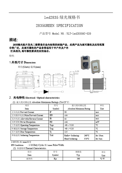
led2835绿光规格书2835GREEN SPECIFICATION产品型号 Model NO.:YLT-led2835GC-520描述:2835绿光贴片发光二极管是行业内标准的封装产品,此类产品为高可靠性及应用范围非常广泛,此高可靠性的产品非常适用于半户外及户外灯具相关,高可靠性要求的应用场合。
特性:1.外形尺寸D imensions单位(Units):毫米(mm)2.光电特性Electrical / Optical characteristics1/10周期, 0.1 msec脉宽IFP Conditions : 1/10 Duty Cycle, 0.1 msec Pulse Width.½ Rja = Heat resistance from Dice to Ambient temperature (Ta) Rjs = Heat resistance from Dice to Solder temperature of Cathode Side (Ts) (3) 原始光电参数Initial Electrical/Optical Characteristics (TA=25ºC)(4)发光强度范围Luminous Intensity Ranking (TA=25ºC)允许误差± 10%Luminous Intensity Measurement allowance is ± 10%.(5)颜色范围Color Ranking (TA=25ºC)允许误差± 0.01Color Coordinates Measurement allowance is ± 0.01.3.包装PACKAGING(1)LEDS在装带之后纸箱包装. The LEDs are packed in cardboard boxes after taping.(2)装带规格Taping Specifications (单位:毫米Units:mm)(3)卷轴尺寸Reel Dimension装带数量2000个/卷2000Pcs/Reel(3) 最小包装标签注明以下:产品名称.批号.光电范围.数量.The label on the minimum packing unit shows ; Part Number, Lot Number, Ranking, Quantity.(4)请注意防水防潮Keep away from wate r, moisture in order to protect the LEDs.(5) 须采取适当防护措施,以防包装箱跌落或受到强力撞击造成对产品的损伤.The LEDS may be damaged if the boxes are dropped or receive a strong impact against them. so precautions must be taken to prevent any damage.4.可靠性RELIABILITY*) U.S.L.:Upper Standard Level **) L.S.L.:Lower Standard Level5.注意事项Cautions(1) 焊接条件Soldering Conditions本产品最多只可回焊两次,且在首次回焊后须冷却至室温之后方可进行第二次回焊.Number of reflow process shall be less than 2 times and cooling process to normal temperature is required between first and Second soldering process. 推荐焊接条件(Recommended soldering conditions)有铅回焊(Lead Solder )无铅回焊(Lead-Free Solder)推荐焊盘式样(Recommended Soldering Pattern ) 单位:毫米( Units:mm )(2)静电Static Electricity触摸LED时,推荐使用防静电手腕带或防静电手套.It is recommended that a wrist band or an anti-electrostatic glove be used when handling the LEDs.所有装置、设备、机器均应接地.All devices, equipment and machinery must be properly grounded.静电损坏的LED会显示出异常特征:正向电压变低或在低电流时死灯.标准: I F=0.5mA时, V F > 2.0VDamaged LEDs will show some unusual characteristics such as the forward voltage becomes lower, or the LEDs do not light at the low current. Criteria : (V F > 2.0V at I F=0.5mA)(3)防潮包装Moisture Proof Package使用防潮包装It is recommended that moisture proof package be used .(4)储藏Storage打开包装袋之前,LED在温度为30°C或更低湿度70%RH以下,可保存一年.Before opening the package ,The LEDs should be kept at 30°C or less and 70%RH or less. The LEDs should be used within a year.(5)打开包装之后,应在24hrs 内焊接完毕.After opening the package, The LEDs should be soldered within 24 hours (1days) after opening the package. If unused LEDs remain, they should be stored in moisture proof packages, such as sealed containers with packages of moisture absorbent material (silica gel).下列情况发生时,须要在焊接前重新烘烤60 ± 5°C,24小时以上。
Bridgelux SMD 2835 1W 9V Thrive产品数据手册说明书
Product Data Sheet DS312Bridgelux Thrive™ combines unique chip, phosphor and packaging technology to closely match the spectra of natural light over the visible wavelength range. Thrive can be used in constant color point luminaires to bring full spectrum natural light indoors or in tunable white luminaires to incorporate circadian elements that may impact human well-being. The high fidelity spectral output of Thrive creates stunning environments with excellent color rendering and outstanding TM30 metrics. Thrive is available in both SMD components and LED arrays to enable a broad range of lighting applications including retail, hospitality, office, education, architectural, museums, healthcare and residential lighting.Features• Engineered spectra to closely match natural light • CRI > 95, R1-R15 >90, high Rf and Rg values• High efficiency full spectrum solution• No violet chip augmentation• Hot color targeted• Industry standard 2835 footprint• Broad product platform availability (SMDs and COBs)Benefits• Full consistent spectrum with fewer spectral spikes • Natural and vivid color rendering• Greater energy savings, lower utility costs• Economical, high efficiency solution• Uniform and consistent white light under application conditions• Ease of design and rapid go-to-market• Enables greater design flexibility and platform color consistencyContentsProduct Feature Map2 Product Nomenclature2 Product Test Conditions2 Product Selection Guide3 Spectrum Characteristics4 Electrical Characteristics7 Absolute Maximum Ratings8 Product Bin Definitions9 Performance Curves12 Typical Radiation Pattern13 Mechanical Dimensions14 Reliability 15 Reflow Characteristics16 Packaging17 Design Resources19 Precautions19 Disclaimers19 About Bridgelux20Product Feature MapYellow phosphor Light Emitting Surface (LES)Product NomenclatureThe part number designation for Bridgelux SMD 2835 is explained as follows:Product Test ConditionsBridgelux SMD 2835 LEDs are tested and binned with a 10ms pulse of 150mA at T j (junction temperature)=T sp (solder point temperature) =25°C. Forward voltage and luminous flux are binned at a T j =T sp =25°C, while color is hot targeted at a T sp of 85°C.1 2 3 4 5 6 7 8 9 10 11 12 13 14 15 16Product FamilyColor Bin OptionsFlux BinsMinimum CRIS = ThriveForward Voltage Bins Nominal CCT27 = 2,700K 30 = 3,000K 40 = 4,000K 50 = 5,000KBXEN – 27 S – 1 1 M – 3 C –00 – 0 – 0Product VersionMid PowerDie count in parallelTypical Forward Voltage Die count in series Bridgelux SMD LED products come in industry standard package sizes and follow ANSI binning standards. These LEDs are optimized for cost and performance, helping to ensure highly competitive system lumen per dollar performance while addressing the stringent efficacy and reliability standards required for modern lighting applications.The following product configurations are available:7,8Notes for Tables 1 & 2:1. The last 6 characters (including hyphens ‘-’) refer to flux bins, forward voltage bins, and color bin options, respectively. “00-0-0” denotes the full distribution of flux, forward voltage, and 6 SDCM color.Example: BXEN-27S-11M-3C-00-0-0 refers to the full distribution of flux, forward voltage, and color within a 2700K 6-step ANSI standardchromaticity region with a minimum of 97 CRI, 1x1 die configuration, mid power, 3.1V typical forward voltage.2. Product CCT is hot targeted at Tsp= 85°C. Nominal CCT as defined by ANSI C78.377-2011.3. Listed CRIs are minimum values and include test tolerance.4. Products tested under pulsed condition (10ms pulse width) at nominal drive current where Tj =Tsp=25°C.5. Bridgelux maintains a ±7.5% tolerance on luminous flux measurements, ±0.1V tolerance on forward voltage measurements, and ±2 tolerance onCRI measurements for the SMD 2835.6. Refer to Table 6 and Table 7 for Bridgelux SMD 2835 Luminous Flux Binning and Forward Voltage Binning information.7. Typical pulsed test performance values are provided as reference only and are not a guarantee of performance.8. Typical performance is estimated based on operation under pulsed current with LED emitter mounted onto a heat sink with thermal interfacematerial and the solder point temperature maintained at 85°C. Based on Bridgelux test setup, values may vary depending on the thermal design of the luminaire and/or the exposed environment to which the product is subjected.9. Photosynthetic Photon Flux is measure of photon flux in the 400nm-700nm region.Product Selection Guide1Note for Table 3:1. Bridgelux maintains a tolerance of ± 3 on Color Rendering Index R1-R15 measurements and TM-30 measurements.2. Rn reference by Nominal Drive Current will have deviations when changed drive current .Figure 1: 2700K Thrive TM-30 GraphsFigure 2: 3000K Thrive TM-30 GraphsFigure 3: 4000K Thrive TM-30 GraphsFigure 4: 5000K Thrive TM-30 GraphsSpectral Matching to Natural LightHumans have evolved and thrived for millions of years under the sun’s natural daylight. While discussions continue regarding the development of LED prod-ucts with artificial spectra aimed at increasing productivity and focus or helping with relaxation, the long-term physiological effects of such altered environBridgelux Thrive is engineered to provide the closest match to natural light using proprietary chip, phosphor and packaging technology. Bridgelux is working with our customers and industry partners to define new metrics to describe and quantify this spectral matching; going beyond today’s quality of light metricsTo quantify spectral matching, Bridgelux has defined a new term; Average Spectral Difference (ASD). ASD is calculated by measuring the absolute difference between the LED spectrum and a natural light source spectrum at discrete wavelengths. These values are then averaged across different wavelength ranges and reported as a percentage. Natural light is defined by the Black Body Curve for sources below 5000K or by the CIE Standard Illuminant D for sources ofBridgelux Thrive has an ASD between 3% and 7% for all color points (2700K – 6500K) across the typical LED wavelength range of 440-650nm. This includes a very close spectral match, with an ASD of only 2% for some color point options, in the blue/cyan color range where most other LED light sources suffer. For comparison purposes, standard 80, 90 and 98 CRI light sources have an ASD that is 2-6 times larger than Thrive over the same wavelength range and up to 20 times greater in the cyan wavelength range.As the industry evolves toward human centric lighting, Bridgelux will work with our customers and industry experts to educate the market about the benefits of the ASD metric to further quantify the quality of light.Table 4:Electrical Characteristics1. The last 6 characters (including hyphens ‘-’) refer to flux bins, forward voltage bins, and color bin options, respectively. “00-0-00” denotes the full distribution of flux, forward voltage, and 6 SDCM color.Example: BXEN-27S-11M-3C-00-0-0 refers to the full distribution of flux, forward voltage, and color within a 2700K 6-step ANSI standardchromaticity region with a minimum of 97 CRI, 1x1 die configuration, mid power, 3.1V typical forward voltage.2. Bridgelux maintains a tolerance of ± 0.1V on forward voltage measurements. Voltage minimum and maximum values at the nominal drive current are guaranteed by 100% test.3. Products tested under pulsed condition (10ms pulse width) at nominal drive current where Tsp = 25°C.4. Thermal resistance value was calculated using total electrical input power; optical power was not subtracted from input power.Absolute Maximum RatingsNotes for Table 5:1. Bridgelux recommends a maximum duty cycle of 10% and pulse width of 10 ms when operating LED SMD at maximum peak pulsed current specified. Maxi-mum peak pulsed current indicate values where LED SMD can be driven without catastrophic failures.2. Light emitting diodes are not designed to be driven in reverse voltage and will not produce light under this condition. no rating is provided.Product Bin DefinitionsTable 6 lists the standard photometric luminous flux bins for Bridgelux SMD 2835 LEDs. Although several bins are listed, product availability in a particular bin varies by production run and by product performance. Not all bins are available in all CCTs.Note for Table 6:1. Bridgelux maintains a tolerance of ± 7.5% on luminous flux measurementsNote for Table 7:1. Bridgelux maintains a tolerance of ± 0.1V on forward voltage measurements.Product Bin DefinitionsNotes for Table 8:=85°C unless otherwise specified1. Color binning at Tsp2. Bridgelux maintains a tolerance of ± 0.007 on x and y color coordinates in the CIE 1931 color space.Product Bin DefinitionsFigure 6: C.I.E. 1931 Chromaticity Diagram (Color Targeted at T=85°C)Performance CurvesNote for Figures 7-11:1. Bridgelux does not recommend driving high power LEDs at low currents. Doing so may produce unpredictable results. Pulse width modulation (PWM) is recommended for dimming effects.2. Characteristics shown for warm white based on 2700K.3. Characteristics shown for neutral white based on 4000K.4. Characteristics shown for cool white based on 5000K.5. For other color SKUs, the shift in color will vary. Please contact your Bridgelux Sales Representative for more information .Figure 7: Drive Current vs. Voltage (T sp =25°C)Figure 8: Typical Relative Luminous Flux vs. Drive Current (T sp =25°C)1Figure 9: Typical Relative Flux vs. Solder Point Temperature 2,3,4,5Figure 10: Typical ccx Shift vs. Solder Point Temperature 2,3,4,5Figure 11: Typical ccy Shift vs. Solder Point Temperature 2,3,4,503060901201502.62.72.8 2.93.03.1F o r w a r d C u r r e n t (m A )Forward Voltage (V)0%25%50%75%100%0306090120150R e l a t i v e L u m i n o u s F l u xForward Current (mA)80%85%90%95%100%0255075100125R e l a t i v e L u m i n o u s F l u xSolder Point Temperature (℃)Warm White Neutral White Cool White-0.004-0.003-0.002-0.0010.000255075100125c c x S h i f tSolder Point Temperature (℃)Warm White Neutral White Cool White-0.008-0.006-0.004-0.0020.000255075100125c c y S h i f tSolder Point Temperature(℃)Warm White Neutral White Cool WhiteTypical Radiation PatternFigure 12: Typical Spatial Radiation Pattern at 150mA, T sp =25°CFigure 13: Typical Polar Radiation Pattern at 150mA, T sp =25°CNotes for Figure 12:1. Typical viewing angle is 116⁰.2.The viewing angle is defined as the off axis angle from the centerline where luminous intensity (Iv) is ½ of the peak value.Mechanical Dimensions Figure 14: Drawing for SMD 2835Notes for Figure 14:1. Drawings are not to scale.2. Drawing dimensions are in millimeters.3. Unless otherwise specified, tolerances are ± 0.10mm.ReliabilityTable 9:Reliability Test Items and ConditionsNotes for Table 9:1. Measurements are performed after allowing the LEDs to return to room temperature2. Tsld : reflow soldering temperature; Ta: ambient temperatureFigure 15 : Reflow ProfileReflow CharacteristicsFigure 16 : Pick and PlaceNote for Figure 16:1. When using a pick and place machine, choose a nozzle that has a larger diameter than the LED’s emitting surface. Using a Pick-and-Place nozzle witha smaller diameter than the size of the LEDs emitting surface will cause damage and may also cause the LED to not illuminate.Is greater than LEDsemitting surfacePackagingFigure 17: Emitter Reel DrawingsNote for Figure 17:1. Drawings are not to scale. Drawing dimensions are in millimeters.Figure 18: Emitter Tape DrawingsNote for Figure 18:1. Drawings are not to scale. Drawing dimensions are in millimeters.PackagingFigure 19: SMD 2835 Packaging and LabelingNote for Figure 19:1. Drawings are not to scale.Design ResourcesDisclaimersPrecautionsPlease contact your Bridgelux sales representative for assistance.MINOR PRODUCT CHANGE POLICYThe rigorous qualification testing on products offered by Bridgelux provides performance assurance. Slight cosmetic changes that do not affect form, fit, or function may occur as Bridgelux continues product optimization.CAUTION: CHEMICAL EXPOSURE HAZARDExposure to some chemicals commonly used in luminaire manufacturing and assembly can cause damage to the LED emitter. Please consult Bridgelux Application Note AN51 for additional information.CAUTION: EYE SAFETYEye safety classification for the use of Bridgelux SMD LED emitter is in accordance with IECspecification EN62778: Application of IEC 62471 for the assessment of blue light hazard to light sources and luminaires are classified as Risk Group 1 when operat -ed at or below the maximum drive current. Please use appropriate precautions. It is important that employees working with LEDs are trained to use them safely.CAUTION: RISK OF BURNDo not touch the SMD LED emitter during operation. Allow the emitter to cool for a sufficient period of time before handling. The SMD LED emitter may reachelevated temperatures such that could burn skin when touched.CAUTIONCONTACT WITH LIGHT EMITTING SURFACE (LES) Avoid any contact with the LES. Do not touch the LES of the emitter or apply stress to the LES (yellow phosphor resin area). Contact may cause damage to the emitterOptics and reflectors must not be mounted in contact with the LES (yellow phosphor resin area).STANDARD TEST CONDITIONSUnless otherwise stated, LED emitter testing is performed at the nominal drive current.About Bridgelux: Bridging Light and Life ™© 2020 Bridgelux, Inc. Product specifications are subject to change without notice. Bridgelux and the Bridgelux stylized logo design are registered trademarks of Bridgelux, Inc. Thrive is a trademark of Bridgelux, Inc. All other trademarks are the property of their respective owners.46430 Fremont Boulevard Fremont, CA 94538 USA Tel (925) At Bridgelux, we help companies, industries and people experience the power and possibility of light. Since 2002, we’ve designed LED solutions that are high performing, energy efficient, cost effective and easy to integrate. Our focus is on light’s impact on human behavior, delivering products that create better environments, experiences and returns—both experiential and financial. And our patented technology drives new platforms for commercial and industrial luminaires.For more information about the company, please visit /Bridgelux /Bridgelux/company/bridgelux-inc-_/user/Bridgelux WeChat ID: BridgeluxInChina。
2835参数

2835灯珠包括:0.2W和0.5W两种=====================================================================【0.2W相关参数如下-中之光电】封装尺寸:2.8 (长) ×3.5 (宽) ×0.8 (厚) mm采用硅胶封装防紫外线(1800K- 15000K) 可供白光(1800K- 15000K)(2θ1/2=120°) 宽角度(2θ1/2=120°)t (Ta = 25 OC)在25 OC 环境温度下的电性和光学额定值;Parameter 参数Symbol 符号Value 数值Unit 单位Reverse Voltage 反向电压VR 5 VForward Current 正向电流IF 60 mAPulse Forward Current (@ 100 μs)脉冲正向电流IFP 100 mAPower Dissipation 耗散功率Pd 200 mWOperating Temperature Range 工作温度Topr - 30 to + 80 OCStorage Temperature Range 储存温度Tstg - 30 to + 80 OCForward Voltage 正向电压at IF = 60 mA VF 2.8-3.8 VReverse Current 反向漏电电流at VR = 5 V IR 10 μ AView Angle 发光角度at IF = 60 mA 2θ 1/2 120 degCorrelated Color Temperature 色温at IF = 60 mA CCT 2200-12000 KLuminous Flux 光通量at IF=60 mA 【20-22(lm)】【22-26(lm)】=====================================================================【0.5W相关参数如下-中之光电】Package Size 封装尺寸:2.8 (长) ×3.5 (宽) ×0.8 (厚) mmSilicone Packed 采用硅胶封装Anti UV 防紫外线White colors are available in(1800K- 15000K) 可供白光(1800K- 15000K)Wide viewing angle (2θ1/2=120°) 宽角度(2θ1/2=120°)Maximum Ratings Characteristics at (Ta = 25 OC)在25 OC 环境温度下的电性和光学额定值;Parameter 参数Symbol 符号Value 数值Unit 单位Reverse Voltage 反向电压VR 5 VForward Current 正向电流IF 150 mAPulse Forwa rd Current (@ 100 μs)脉冲正向电流IFP 700 mAPower Dissipation 耗散功率Pd 500 mWOperating Temperature Range 工作温度Topr - 30 to + 80 OCStorage Temperature Range 储存温度Tstg - 30 to + 80 OCForward Voltage 正向电压at IF = 150 mA VF 2.8-3.8 VReverse Current 反向漏电电流at VR = 5 V IR 10 μ AView Angle 发光角度at IF = 150 mA 2θ 1/2 120 degCorrelated Color Temperature 色温at IF = 150 mA CCT 2200-12000 KLuminous Flux 光通量at IF=150 mA 【30-35(lm)】【35-40(lm)】【40-45(lm)】【45-50(lm)】【50-55(lm)】。
led2835绿光贴片灯珠规格书
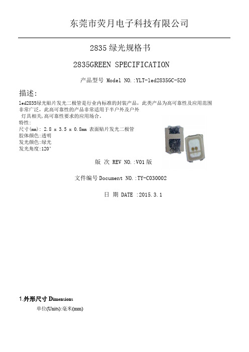
东莞市荧月电子科技有限公司2835绿光规格书2835GREEN SPECIFICATION产品型号 Model NO.:YLT-led2835GC-520描述:led2835绿光贴片发光二极管是行业内标准的封装产品,此类产品为高可靠性及应用范围非常广泛,此高可靠性的产品非常适用于半户外及户外灯具相关,高可靠性要求的应用场合。
特性:尺寸(mm): 2.8 x 3.5 x 0.8mm 表面贴片发光二极管胶体颜色:透明发光颜色:绿光发光角度:120°版次 REV NO.:V01版文件编号Document NO.:TY-C030002日期 DATE :2015.3.11.外形尺寸D imensions单位(Units):毫米(mm)2.光电特性Electrical / Optical characteristics1/10周期, 0.1 msec脉宽IFP Conditions : 1/10 Duty Cycle, 0.1 msec Pulse Width.½ Rja = Heat resistance from Dice to Ambient temperature (Ta) Rjs = Heat resistance from Dice to Solder temperature of Cathode Side (Ts) (3) 原始光电参数Initial Electrical/Optical Characteristics (TA=25ºC)(4)发光强度范围Luminous Intensity Ranking (TA=25ºC)允许误差± 10%Luminous Intensity Measurement allowance is ± 10%.(5)颜色范围Color Ranking (TA=25ºC)允许误差± 0.01Color Coordinates Measurement allowance is ± 0.01.3.包装PACKAGING(1)LEDS在装带之后纸箱包装. The LEDs are packed in cardboard boxes after taping.(2)装带规格Taping Specifications (单位:毫米Units:mm)(3)卷轴尺寸Reel Dimension装带数量2000个/卷2000Pcs/Reel(3) 最小包装标签注明以下:产品名称.批号.光电范围.数量.The label on the minimum packing unit shows ; Part Number, Lot Number, Ranking, Quantity.(4)请注意防水防潮Keep away from wate r, moisture in order to protect the LEDs.(5) 须采取适当防护措施,以防包装箱跌落或受到强力撞击造成对产品的损伤.The LEDS may be damaged if the boxes are dropped or receive a strong impact against them. so precautions must be taken to prevent any damage.4.可靠性RELIABILITY*) U.S.L.:Upper Standard Level **) L.S.L.:Lower Standard Level 5.注意事项Cautions(1) 焊接条件Soldering Conditions本产品最多只可回焊两次,且在首次回焊后须冷却至室温之后方可进行第二次回焊.Number of reflow process shall be less than 2 times and cooling process to normal temperature is required between first and Second soldering process. 推荐焊接条件(Recommended soldering conditions)有铅回焊(Lead Solder ) 无铅回焊(Lead-Free Solder)推荐焊盘式样(Recommended Soldering Pattern ) 单位:毫米( Units:mm)(2)静电 Static Electricity触摸LED 时,推荐使用防静电手腕带或防静电手套.It is recommended that a wrist band or an anti-electrostatic glove be used when handling the LEDs. 所有装置、设备、机器均应接地.All devices, equipment and machinery must be properly grounded.静电损坏的LED 会显示出异常特征:正向电压变低或在低电流时死灯.标准: I F =0.5mA 时, V F > 2.0VDamaged LEDs will show some unusual characteristics such as the forward voltage becomes lower, or the LEDs do not light at the low current. Criteria : (V F > 2.0V at I F =0.5mA) (3)防潮包装Moisture Proof Package使用防潮包装It is recommended that moisture proof package be used .(4)储藏Storage打开包装袋之前,LED在温度为30°C或更低湿度70%RH以下,可保存一年.Before opening the package ,The LEDs should be kept at 30°C or less and 70%RH or less. The LEDs should be used within a year.(5)打开包装之后,应在24hrs 内焊接完毕.After opening the package, The LEDs should be soldered within 24 hours (1days) after opening the package. If unused LEDs remain, they should be stored in moisture proof packages, such as sealed containers with packages of moisture absorbent material (silica gel).下列情况发生时,须要在焊接前重新烘烤60 ± 5°C,24小时以上。
SMD LED

SMD LED1简介SMD LED就是表面贴装发光二极管的意思,SMD贴片有助于生产效率提高,满足不同设施应用。
是一种固态的半导体器件,它可以直接把电转化为光。
它的电压为1.9-3.2V,红光、黄光电压最低,LED的心脏是一个半导体的晶片,晶片的一端附在一个支架上,一端是负极,另一端连接电源的正极,使整个晶片被环氧树脂封装起来。
半导体晶片由两部分组成,一部分是P型半导体,在它里面空穴占主导地位,另一端是N型半导体,在这边主要是电子。
但这两种半导体连接起来的时候,它们之间就形成一个P-N结。
当电流通过导线作用于这个晶片的时候,电子就会被推向P区,在P区里电子跟空穴复合,然后就会以光子的形式发出能量,这就是LED发光的原理。
而光的波长也就是光的颜色,是由形成P-N结的材料决定的。
2SMD LED 主要型号SMD LED 35283528贴片灯珠,功率0.06w,流明值6-7LM,7-8LM,8-9LM,光效最高可以达到150LM/w。
SMD LED 28352835贴片灯珠,功率0.2w,流明值20-22LM,22-24LM,24-26LM,光效最高可以达到130LM/w。
SMD LED 50505050贴片灯珠,功率0.2w,流明值20-22LM,22-24LM,24-26LM,光效最高可以达到130LM/w。
SMD LED 56305630贴片灯珠,功率0.5w,流明值50-55LM,55-60LM,光效最高可以达到130LM/w。
SMD LED 30143014贴片灯珠,功率0.1w,流明值11-12LM,12-13LM,光效最高可以达到130LM/w。
3LED&SMD 比较首先,我们来了解LED和SMD的概念。
LED( Light Emitting Diode)是发光二极管,有很多种,其中一种就是SMD的LED。
其它的如直插式LED、食人鱼、大功率LED等。
而SMD形式封装的LED 又分CHIP、TOP、SIDEVIEW等若干种。
- 1、下载文档前请自行甄别文档内容的完整性,平台不提供额外的编辑、内容补充、找答案等附加服务。
- 2、"仅部分预览"的文档,不可在线预览部分如存在完整性等问题,可反馈申请退款(可完整预览的文档不适用该条件!)。
- 3、如文档侵犯您的权益,请联系客服反馈,我们会尽快为您处理(人工客服工作时间:9:00-18:30)。
廣東省廣州市荔灣區芳村東沙荷景路9號(東朗工業園)2棟201
電話:+86-20-81402798 81414708 傳真:81402027 E-mail:xhm@ SMD LED PRODUCT SPCIFICATION
2835 Single chip
DESCRIPTION
White smd led(0.2W)
CUSTOMER
DATE
REV v1.0
PREPARED CHECK APPROVED LumenMax
Customer
Revision Note
Date Revision Page Vision
2012/4/14Initiate Document2~11V1.0
1. Features
Samll Size(2.8*3.5*0.8mm)
Industry Standard Footprint
High Efficiency
Pb-Free
Soldering methods: IR reflow soldering Chip Dice: InGaN
2. Dimensions
Unit:mm Tolerance:±0.1mm
Cathode mark
2.00
3.30
2.80 2.60
2.10
0.60 3.50
0.25
2.10 1.90
0.80
1 2
2
1
3. Reconnended Soldering Pattern(Units:mm)
4.00
0.60 2.50
2.10
4. Typical Electrical & Optical Characteristics(Ta=25°)
Items Symbol Condition Device Min. Typ. Max. Unit Forward voltage VF I F=60mA 2.9 --- 3.5 V
Reverse Current IR VR=5V --- --- 10 μA
Color temperature TC I F=60mA 6000 6300 6700 K
Luminous Flux ¢V I F=60mA 22 23 24 LM
View Angle 2θ 1/2 I F=60mA --- 120 ---
Notes:
1.Luminous Intensity: +/-10%
2. Forward Voltage: +/-0.1V.
5.Absolute Maxinum Ratings at (Ta=25°)
Parameter Rating Units
Power dissipation 120 mW
DC Forward Current 100 mA
Peak Forward Current[1] 150 mA
Reverse Voltage 5 V
Operating Temperature -40°C To +85°C
Storage Temperature -40°C To +85°C
Note:
1. 1/10 Duty Cycle, 0.1ms Pulse Width.
6. Electro-optical characteristics at(Ta=25℃)
Parameter
Value Unit
Min.
Max.
Forward voltage
07 2.8 3.0 V
08 3.0 3.2 09 3.2 3.4 10
3.4
3.6
Notes:
1. Luminous Intensity: +/-10%
2. Forward Voltage: +/-0.1V.
7. Typical optical characteristics curves
8. Chromaticity Bin
Cool white CIE
M4
M3
M2
M1
YA2
YA1
E2
E1
Warm white CIE
YF3
YG3
YG4
YG5
YG6 YF6 YF5 YF4
9. Reflow profile
■Temperature-profile (Surface of circuit board)
1. Reflow soldering should not be done more than two times
2. When soldering ,do not put stress on the LEDs during heating
10. Packaging Specificatio
● Feeding Direction
● Dimensions of Reel (Unit: mm) ● Reel
3000 PCS
● Dimensions of Tape (Unit: mm)
11. Packaging specifications
A 8.0mm
B 178.0mm
C 60.0mm D
13.0mm。
