Thin-mini ITX Motherboard-Introduce
主板的介绍
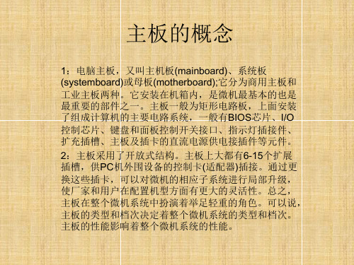
4:硬盘接口
(1)古老的ide接口,主要是老式机械硬盘
(2)常见主流是ta接口,有sata2,sata3 接口区别,速度sata3快些,主要是现在的机 械硬盘或者普通的固态硬盘
8:主板io挡板部分接口
1:ps/2键鼠接口,是老式键盘鼠标用的 2:vga,hdmi,dvi接口,这个给cpu集显用 的,没有集显或者有了独显,这些接口就被 屏蔽了 3:usb2.0和usb3.0接口,有线网卡接口,音 响,麦克,输入接口,有些主板还有无线wifi 网卡
9.主板pcb
1:PCB( Printed Circuit Board),中文名 称为印制电路板,又称印刷线路板,是重要 的电子部件,是电子元器件的支撑体,是电 子元器件电气连接的载体。由于它是采用电 子印刷术制作的,故被称为“印刷”电路板 。 2:pcb是越多越好,有4层,6层,8层
主板的简介
1:典型的主板能提供一系列接合点,供处理器、显卡、声 效卡、硬盘、存储器、对外设备等设备接合。它们通常直接 插入有关插槽,或用线路连接。主板上最重要的构成组件是 芯片组(Chipset)。而芯片组通常由北桥和南桥组成,现在北 桥融合进CPU里面,南桥还在主板上。这些芯片组为主板提 供一个通用平台供不同设备连接,控制不同设备的沟通。它 亦包含对不同扩充插槽的支持,例如处理器、PCI、ISA、 AGP,和PCI Express。芯片组亦为主板提供额外功能,例 如集成显卡,集成声卡(也称内置显卡和内置声卡)。一些高 价主板也集成红外通讯技术、蓝牙和802.11(Wi-Fi)等功能。
6:主板的机箱usb,音频接口
薄型化的更多可能Intel推動主機板新規格ThinMini-ITX

薄型化的更多可能Intel推動主機板新規格ThinMini-ITX在COMPUTEX上,英特尔正式推出了Thin Mini-ITX主板规范,Thin Mini-ITX主板大小保留了Mini-ITX的6.7 x 6.7英寸规格。
但是,如图所示,其I/O挡板将不超过一英寸高(25毫米),而不是普通Mini-ITX主板的一点七三英寸(44毫米)。
标准的Mini - ITX主板(左)Thin Mini-ITX主板(右)英特尔还表示,凭借空间上的节省,这种超薄主板可以更好的应用于超薄个人电脑、推车、医院、自动柜员机等。
而且,Thin Mini-ITX主板尺寸同样适用于目前的Mini-ITX机箱,这也使其在桌面市场中具有了更广泛的空间。
目前英特尔公司没有公布关于Thin Mini-ITX主板的更多细节。
作为第一款英特尔公司的Thin Mini-ITX主板,其型号为D945GSEJT,这款主板采用了英特尔Atom N270处理器与945GSE芯片组。
Thin Mini-ITX主板的主要概括介绍:主板最高支持TDP功耗为65瓦的桌面级CPU显示器接口为LVDS和DP接口(嵌入式DisplayPort)内部显示连接器内存支持SODIMM外部电源供应器(通过背面I/O面板)Mini PCI Express扩展插槽据业内人士介绍,英特尔目前正在与台湾精英电脑系统公司(ECS),神达和微星已经开始商业合作。
而在本周的CeBit展会上神达公司就显示了旗下采用Thin Mini-ITX主板的Maestro 650一体机产品。
如果讀者還有印象的話,距離前一次Intel推行主機板規格,已經是將近十年,2003年推出 BTX(Balanced Technology Extended)的事了。
不過最後因平台建置成本提昇,大幅更改的孔位、零件配置,無法相容前代規格,而不被廠商以及消費市場買單。
其推行路之艱辛與慘澹,最後Intel不得不自行跳出來宣告放棄收場。
了解电脑主板常见型号和功能解析

了解电脑主板常见型号和功能解析电脑主板(Motherboard)是电脑的核心部件之一,承载着各种硬件设备的连接和协调工作。
不同的主板型号和功能特点对电脑的性能和扩展能力有着重要影响。
本文将为您详细介绍电脑主板的常见型号和功能解析,帮助您更好地了解主板的选择和应用。
一、主板型号的分类根据不同的标准,主板可以分为多种不同的型号。
以下是常见的分类方式:1.1 基于处理器类型的分类根据主板所支持的处理器类型,主板可分为Intel主板和AMD主板两大类。
Intel主板主要适用于搭载Intel处理器的电脑,而AMD主板则适用于搭载AMD处理器的电脑。
1.2 根据主板尺寸的分类主板尺寸是指主板外形的大小和布局。
常见的主板尺寸包括ATX、Micro-ATX和Mini-ITX等。
ATX主板尺寸较大,适用于台式机和服务器等需要较多扩展槽位的场合;Micro-ATX主板相对较小,适用于一般家用电脑;Mini-ITX主板则更小巧,适用于小型电脑或嵌入式系统。
1.3 根据主板芯片组的分类主板芯片组是主板的核心之一,负责控制各个部件的协调工作。
常见的主板芯片组包括Intel的Z系列、H系列、B系列等,以及AMD的A系列、B系列等。
不同芯片组提供的功能和扩展性不同,用户在选择主板时应根据自己的需求进行合理的选择。
二、主板的常见功能解析除了基本的连接硬件设备和协调工作外,主板还拥有许多其他常见的功能。
以下是几个常见的主板功能解析:2.1 内存插槽主板上的内存插槽用于安装内存条,不同主板的内存插槽数量和类型也有所不同。
主板上的内存插槽型号常见的有DDR3、DDR4等,用户在购买内存时需要根据主板所支持的类型进行选择。
2.2 PCI-E插槽PCI-E插槽可以用于插入显卡、声卡、网卡等扩展卡。
主板上的PCI-E插槽数量和版本也会影响到电脑的扩展能力和性能。
一般来说,PCI-E插槽的版本越高,其传输速度和带宽也会相应增加。
2.3 SATA接口SATA接口用于连接硬盘、光驱等存储设备。
介绍主板的英文作文

介绍主板的英文作文英文:As a computer enthusiast, I have always been fascinated by the motherboard. The motherboard, also known as the mainboard or system board, is the backbone of any computer system. It is responsible for connecting all the different components of a computer, including the CPU, RAM, storage devices, and peripherals.One of the most important features of a motherboard is its chipset. The chipset is a set of electronic components that manages the communication between the CPU and other components on the motherboard. Different chipsets have different capabilities, such as supporting different types of CPUs or RAM.Another important aspect of a motherboard is its form factor. The form factor determines the physical size and layout of the motherboard, which in turn affects the sizeand shape of the computer case. Common form factors include ATX, micro-ATX, and mini-ITX.The motherboard also includes a variety of ports and connectors for connecting peripherals such as USB devices, audio devices, and networking equipment. These ports and connectors can be located on the motherboard itself or on expansion cards that plug into the motherboard.Overall, the motherboard is a critical component of any computer system. It determines what other components can be used and how they are connected, so it is important to choose a motherboard that meets your needs and supports the components you want to use.中文:作为一名电脑爱好者,我一直被主板所吸引。
计算机术语主板类都有哪些

计算机术语主板类都有哪些计算机的主板是电脑中最重要的部件之一,它承载着计算机的各种关键组件并连接它们。
下面是一些常见的计算机术语主板类别:2. MicroATX(µATX)主板:MicroATX主板是小型的ATX主板。
它通常比ATX主板小,尺寸为9.6 x 9.6英寸。
由于其较小的尺寸,它在小型机箱或迷你电脑中使用较为广泛。
3. ITX(Information Technology eXtended)主板:ITX主板是一种更小型的主板类型,尺寸通常为6.7 x 6.7英寸。
它的小尺寸使得它非常适合于紧凑型或移动设备,如小型PC、迷你台式机或家庭媒体中心。
4. BTX(Balanced Technology eXtended)主板:BTX主板是一种设计在ATX主板之后的主板标准。
它旨在提供更好的散热和电源管理,并改善整体的性能和可靠性。
然而,BTX主板并没有被广泛采用,ATX仍然是主流。
5. Mini-ITX主板:Mini-ITX主板是ITX主板的一种更小尺寸的变体,尺寸通常为6.7 x 6.7英寸或更小。
尽管尺寸较小,但它仍然具备一定的扩展性,适合于一些低功耗需求的系统,如家庭办公电脑、嵌入式系统或物联网设备。
6. Extended ATX(E-ATX)主板:E-ATX主板是ATX主板的一种更大尺寸的变体,通常具有更多的扩展插槽和接口。
由于其较大的尺寸,E-ATX主板通常用于高性能工作站或游戏电脑,以支持更多的组件和性能提升。
7.uBTX主板:uBTX主板是BTX主板的一种更小尺寸的变体,尺寸通常为10.5x10.2英寸。
它是一种针对低至中端市场的主板类型,具备较好的散热效果和电源管理。
8. FlexATX主板:FlexATX主板是一种小型化的ATX主板,尺寸通常为9 x 7.5英寸。
该主板类型适用于一些空间有限的系统,如小型迷你台式机、一些商用电脑或嵌入式系统。
除以上列举的主板类别外,还有一些其他的特殊主板类型,例如嵌入式主板、服务器主板、工控主板等,它们针对不同的应用场景和需求设计,具备特定的特征和功能。
asrock a68hi series mini-itx motherboard user 说明书
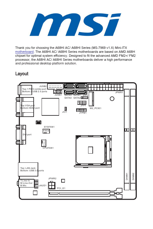
Thank you for choosing the A68HI AC/ A68HI Series (MS-7969 v1.X) Mini-ITXmotherboard . The A68HI AC/ A68HI Series motherboards are based on AMD A68H chipset for optimal system efficiency. Designed to fit the advanced AMD FM2+/ FM2 processor, the A68HI AC/ A68HI Series motherboards deliver a high performance and professional desktop platform solution.LayoutMotherboard SpecificationsBack PanelLAN LED IndicatorLED LED LEDLED Status Description Link/ Activity LEDOffNo link Yellow Linked Blinking Data activity Speed LEDOff10 Mbps connection Green 100 Mbps connection Orange1 Gbps connectionA68HI ACA68HIHDMIUSB 3.0USB 2.0DVI-DAPU & Heatsink InstallationWhen installing a APU, always remember to install a APU heatsink. An APU heatsink is necessary to prevent overheating and maintain system stability. Follow the steps below to ensure correct APU and heatsink installation. Wrong installation can damage both the APU and the motherboard.1.Pull the lever sideways away from the socket. Make sure to raise the lever up toa 90-degree angle.2.Look for the gold arrow of the APU. The gold arrow should point as shown in thepicture. The APU can only fit in the correct orientation.3.If the APU is correctly installed, the pins should be completely embedded intothe socket and can not be seen. Please note that any violation of the correct installation procedures may cause permanent damages to your motherboard. 4.Press the APU down firmly into the socket and close the lever. As the APU islikely to move while the lever is being closed, always close the lever with your fingers pressing tightly on top of the APU to make sure the APU is properly and completely embedded into the socket.5. Locate the APU fan connector on the motherboard.6.Position the cooling set onto the retention mechanism. Hook one end of the clipto hook first.7.Then press down the other end of the clip to fasten the cooling set on the top ofthe retention mechanism. Locate the Fix Lever and lift up it.8.Fasten down the lever.9.Important• While disconnecting the Safety Hook from the fixed bolt, it is necessary to keep an eye on your fingers, because once the Safety Hook is disconnected from the fixed bolt, the fixed lever will spring back instantly.• Confirm that the APU cooler has formed a tight seal with the APU before booting your system.• Please refer to the documentation in the APU cooler package for more details about APU cooler installation.Memory Installationstandard is not backward compatible. Always install DDR3 memory modules in DDR3 DIMM slots.• To ensure system stability, memory modules must be of the same type and density in Dual-Channel mode.Internal ConnectorsJPWR1~2: ATX Power ConnectorsThese connectors allow you to connect an ATX power supply. To connect the ATX power supply, align the power supply cable with the connector and firmly press the cable into the connector. If done correctly, the clip on the power cable should be hooked on the motherboard’s power connector..+3.3V 2V u n d N #105V 11.+.G r o u n d 12.+3.2V 2+12V 1G r supply to ensure stable operation of the motherboard.JAUD1: Front Panel Audio ConnectorThis connector allows you to connect the front audio panel located on your computer case..M I C L I C R 10.H e a d P d P h o n e R N S E _S E N D e a d P h o n e L 8.N o P 6.M I 4.N C 2.G r o uSATA1~4: SATA ConnectorsThis connector is a high-speed SATA interface port. Each connector can connect to one SATA device. SATA devices include disk drives (HDD), solid state drives (SSD), and optical drives (CD/ DVD/ Blu-Ray).SATA1~4 (6Gb/s, by AMD A68H)include disk drives (HDD), solid state drives (SSD), and optical drives (CD / DVD / Blu-Ray). Please refer to the device’s manual for further information. • Many computer cases also require that large SATA devices, such as HDDs, SSDs, and optical drives, be screwed down into the case. Refer to the manual that came with your computer case or your SATA device for further installation instructions. • Please do not fold the SATA cable at a 90-degree angle. Data loss may result during transmission otherwise.• SATA cables have identical plugs on either sides of the cable. However, it isrecommended that the flat connector be connected to the motherboard for space saving purposes.JCI1: Chassis Intrusion ConnectorThis connector connects to the chassis intrusion switch cable. If the computer case is opened, the chassis intrusion mechanism will be activated. The system will record this intrusion and a warning message will flash on screen. To clear the warning, you must enter the BIOS utility and clear the record.2.G N D.C H A S S I SCPUFAN1, SYSFAN1: Fan Power ConnectorsThe fan power connectors support system cooling fans with +12V. If the motherboard has a System Hardware Monitor chipset on-board, you must use a specially designed fan with a speed sensor to take advantage of the CPU fan control. Remember to connect all system fans. Some system fans may not connect to the motherboard and will instead connect to the power supply directly. A system fan can be plugged intou n d2V e n s e .S p e e d C o n t r o recommended CPU heatsink. • These connectors support Smart Fan Control with liner mode. The Command Center utility can be installed to automatically control the fan speeds according to the CPU’s and system’s temperature. • If there are not enough ports on the motherboard to connect all system fans, adapters are available to connect a fan directly to a power supply. • Before first boot up, ensure that there are no cables impeding any fan blades.JTPM1: TPM Module ConnectorThis connector connects to a TPM (Trusted Platform Module). Please refer to the TPM security platform manual for more details and usages.10.N o14.G r o u n 8.5V P 12.G r o 6.S e r a I 4.3.3V P o w 2.3V S t a n d b y .L P C C o c k C R e s e t a d d r e s s & d a t a p n 0d r e s s & d a t a p n 1d d r e s s & d a t a p n 2C a d d r e s s & d a t a p n 3L P C F r a m e21JFP1, JFP2: System Panel ConnectorsThese connectors connect to the front panel switches and LEDs. When installing the front panel connectors, please use the optional M-Connector to simplify installation. Plug all the wires from the computer case into the M-Connector and then plug the M-Connector into the motherboard.10.s e t S w t c h D D L E D P o w e r SwtP o w e r v e dJFP2U Z -.S p e a k e r +.S p e a k e r -U Z +positive wires. Please use the diagrams above and the writing on the optional M-Connectors to determine correct connector orientation and placement. • The majority of the computer case’s front panel connectors will primarily beplugged into JFP1.JUSB1: USB 2.0 Expansion ConnectorThis connector is designed for connecting high-speed USB peripherals such as USBHDDs, digital cameras, MP3 players, printers, modems, and many others.V C C B 0-10.N 0+u n d o P n 8.6.U 4.U S B 2.V C C damage.JUSB2: USB 3.0 Expansion ConnectorThe USB 3.0 port is backwards compatible with USB 2.0 devices. It supports data transfer rates up to 5Gbits/s (SuperSpeed)._C_DN_RX_DPB3_RX_DNowerGround+B20-_C_DP2No19Po1811514U13Gro12USB211USB2damage.• To use a USB 3.0 device, you must connect the device to a USB 3.0 port through an optional USB 3.0 compliant cable.M2_PCIE1: M.2 Key E SlotThis M.2 port supports for both Wi-Fi and Bluetooth module, A68HI AC is already installed the Wi-Fi and Bluetooth combo module and connected to the antenna connectors on the back panel.JBAT1: Clear CMOS JumperThere is CMOS RAM onboard that is external powered from a battery located on the motherboard to save system configuration data. With the CMOS RAM, the system can automatically boot into the operating system (OS) every time it is turned on. If you want to clear the system configuration, set the jumpers to clear the CMOS RAM.11Keep Data Clear DataAfterwards, open the jumper . Do not clear the CMOS RAM while the system is on because it will damage the motherboard.PCI_E1: PCIe Expansion SlotsThe PCIe slot supports the PCIe interface expansion card.PCIe 3.0 x16 Slotunplug the power supply power cable from the power outlet. Read the expansion card’s documentation to check for any necessary additional hardware or software changes.BIOS SetupThe default settings offer the optimal performance for system stability in normal conditions. You may need to run the Setup program when:■An error message appears on the screen during the system booting up, and requests you to run SETUP.■You want to change the default settings for customized features.stability if the system becomes unstable after changing BIOS settings. Select the "Restore Defaults" and press <Enter> in BIOS to load the default settings.• If you are unfamiliar with the BIOS settings, we recommend that you keep the default settings to avoid possible system damage or failure booting due to inappropriate BIOS configuration.Entering BIOS SetupPower on the computer and the system will start the Power On Self Test (POST) process. When the message below appears on the screen, please <DEL> key to enter BIOS:Press DEL key to enter Setup Menu, F11 to enter Boot MenuIf the message disappears before you respond and you still need to enter BIOS, restart the system by turning the computer OFF then back ON or pressing the RESET button. You may also restart the system by simultaneously pressing <Ctrl>, <Alt>, and <Delete> keys.MSI additionally provides a method to enter the BIOS setup. You can click the “GO2BIOS” tab on “MSI Fast Boot” utility screen to enable the system going to BIOS setup directly at next boot.Click "GO2BIOS" tab on "MSI FastBoot" utility screen.setup.OverviewAfter entering BIOS, the following screen is displayed.BIOS menu selectionTemperature monitor SysteminformationBoot device priority barMenu displayBIOS menu selectionLanguageVirtual OC Genie ButtonOC Menu• Overclocking your PC manually is only recommended for advanced users.• Overclocking is not guaranteed, and if done improperly, can void your warranty or severely damage your hardware.• If you are unfamiliar with overclocking, we advise you to use OC Genie for easy overclocking.▶Current CPU/ DRAM FrequencyThese items show the current frequencies of installed CPU and Memory. Read-only.▶CPU Base Frequency (MHz) [Default]Sets the CPU Base clock. You may overclock the CPU by adjusting this value. Please note that overclocking behavior and stability is not guaranteed. This item appears when the installed processor supports this function.▶Adjust CPU Ratio [Auto]Sets the CPU ratio that is used to determine CPU clock speed. This item can only be changed if the processor supports this function.▶Adjusted CPU FrequencyShows the adjusted CPU frequency. Read-only.▶Adjust CPU-NB Ratio [Auto]Sets the CPU-NB ratio that is used to determine CPU-NB clock speed.▶Adjusted CPU-NB FrequencyShows the adjusted CPU-NB frequency. Read-only.▶AMD Turbo Core Technology [Auto]Base on AMD Turbo Core Technology, part of CPU core ratio may pop down for providing more performance headroom for active CPU core, even AMD Cool’n’Quiet Technology is Disabled.[Auto] Turbo Core Technology will linked to AMD Cool’n’QuietTechnology.[Enabled] Enables this function.[Disabled] Disables this function.▶Adjust Turbo Core Ratio [Auto]Specifies the Turbo Core frequency multiplier.▶Adjusted Turbo Core FrequencyShows the adjusted Turbo Core frequency. Read-only.▶Adjust GPU Engine Frequency [Auto]Adjust GPU Engine Frequency.▶Adjusted GPU Engine FrequencyShows the adjusted GPU Engine frequency. Read-only.▶DRAM Frequency [Auto]Sets the DRAM frequency. Please note the overclocking behavior is not guaranteed.▶Adjusted DRAM FrequencyShows the adjusted DRAM frequency. Read-only.▶Intel Extreme Memory Profile (XMP) [Disabled]XMP is the overclocking technology by memory module. This item will be available when you install the memory modules that support XMP technology. When the XMP is Enabled, the AMP will be forced to be disabled.[Disabled] Disables this function.[Profile 1] Uses profile1 over-clocking settings of installed XMP memorymodule.[Profile 2] Uses profile2 over-clocking settings of installed XMP memorymodule.▶DRAM Timing Mode [Auto]Selects the memory timing mode.[Auto] DRAM timings will be determined based on SPD (Serial Presence Detect) of installed memory modules.[Link] Allows user to configure the DRAM timing manually for all memory channel.[UnLink] Allows user to configure the DRAM timing manually for respective memory channel.▶Advanced DRAM ConfigurationPress <Enter> to enter the sub-menu. This sub-menu will be activated after setting [Link] or [Unlink] in “DRAM Timing Mode”. User can set the memory timing for each memory channel. The system may become unstable or unbootable after changing memory timing. If it occurs, please clear the CMOS data and restore the default settings. (Refer to the Clear CMOS jumper/ button section to clear the CMOS data, and enter the BIOS to load the default settings.▶DRAM Voltage [Auto]Sets DRAM voltage. If set to "Auto", BIOS will set DRAM voltage automatically or you can set it manually.▶Spread Spectrum [Enabled]This function reduces the EMI (Electromagnetic Interference) generated by modulating clock generator pulses.[Enabled] Enables the spread spectrum function to reduce the EMI(Electromagnetic Interference) problem.[Disabled] Enhances the overclocking ability of CPU Base clock.• If you do not have any EMI problem, leave the setting at [Disabled] for optimal system stability and performance. But if you are plagued by EMI, select the value of Spread Spectrum for EMI reduction.• The greater the Spread Spectrum value is, the greater the EMI is reduced, and the system will become less stable. For the most suitable Spread Spectrum value, please consult your local EMI regulation.• Remember to disable Spread Spectrum if you are overclocking because even a slight jitter can introduce a temporary boost in clock speed which may just cause your overclocked processor to lock up.▶CPU Memory Changed Detect [Enabled]Enables or disables the system to issue a warning message during boot when the CPU or memory has been replaced.[Enabled] The system will issue a warning message during boot and thanneeds to load the default settings for new devices. [Disabled] Disables this function and keeps the current BIOS settings.▶OC Retry Count [1]When overclocking has failed, setting this item will allow system to reboot specified number of times with the same overclocked configuration. If overclocking has failed every time, the system will restore the defaults.[1], [2], [3] Retry 1,2,3 times.[Disabled] Disables this function and keeps the current BIOS settings.▶CPU SpecificationsPress <Enter> to enter the sub-menu. This sub-menu displays the information of installed CPU. You can also access this information menu at any time by pressing [F4]. Read only.▶CPU Technology SupportPress <Enter> to enter the sub-menu. The sub-menu shows what the keyfeatures does the installed CPU support. Read only.▶MEMORY-ZPress <Enter> to enter the sub-menu. This sub-menu displays all the settings and timings of installed memory. You can also access this information menu at any time by pressing [F5].▶DIMM1~2 Memory SPDPress <Enter> to enter the sub-menu. The sub-menu displays the information of installed memory. Read only.▶CPU FeaturesPress <Enter> to enter the sub-menu.▶AMD Cool’n’Quiet [Auto]Enabled or disabled AMD Cool’n’Quiet function.[Auto] Depends on AMD Design.[Enable] Enables AMD Cool’n’Quiet function. The Cool’n’Quiettechnology can effectively and dynamically lower CPU speedand power consumption.[Disabled] Disables this function.When adjust CPU Ratio then Cool’n’Quiet function will be disabled automatically. For CPU which supports the Turbo Core Tech., please set AMD Turbo Core Technology and AMD Cool’n’Quiet as Disabled to retain the default CPU core speed.▶SVM Mode [Enabled]Enables or disables CPU Virtualization.[Enabled] Enables CPU Virtualization and allows a platform to runmultiple operating systems in independent partitions. Thesystem can function as multiple systems virtually. [Disabled] Disables this function.▶Core C6 State [Enabled]Enables or disables C6 state support.[Enabled] When the CPU enters C6 state, all cores will savearchitectural state and reduce core voltages to zero volts.Wake up the CPU from C6 state will take a lot longer. [Disabled] Disables this function.▶Power Policy ModeSets the NB P-state.[Performance] Disables the NB P-state. High NB frequency is fixed foroptimum performance.[Battery Life] Enables the NB P-state. NB frequency will be changeddynamically.▶cTDP [Auto]Sets TDP for installed APU to fit in platform with thermal and VDD power solutions. If set to “Auto”, BIOS will set it automatically.。
了解电脑主板ATXvsMicroATXvsMiniITX

了解电脑主板ATXvsMicroATXvsMiniITX了解电脑主板:ATX vs MicroATX vs Mini-ITX电脑主板是计算机的核心部件之一,它连接了各个硬件组件,起到了传输数据、供电等关键作用。
在选择主板时,有几种常见的规格可供选择,包括ATX、MicroATX和Mini-ITX。
本文将介绍这三种主板规格的特点和应用领域。
1. ATX主板ATX(Advanced Technology eXtended)是一种最常见的主板规格,它的大小为305mm×244mm。
ATX主板可以容纳更多的扩展插槽和接口,适合需要更多扩展能力和功能的用户。
ATX主板通常具有多个PCIe插槽,用于安装显卡、声卡等拓展卡,以满足高性能用户的需求。
此外,ATX主板还可以支持多个内存插槽,以及更多的SATA(串行ATA)接口和USB接口,方便用户连接更多的存储设备、外设等。
ATX主板一般采用更大的机箱,使得整个计算机组装起来较为宽敞,散热性能也更好。
因此,ATX主板适用于高性能台式电脑,如游戏电脑、工作站等。
2. MicroATX主板MicroATX(或称为mATX)是一种更小尺寸的主板规格,大小通常为244mm×244mm。
相比于ATX主板,MicroATX主板在尺寸上更为紧凑,这使得它适用于那些需要节省空间的情况。
虽然MicroATX主板尺寸较小,但它仍然可以提供相对丰富的扩展能力。
通常,MicroATX主板具有多个PCIe插槽、内存插槽,以及少量的SATA和USB接口,可满足一般用户的需求。
由于尺寸较小,MicroATX主板可以搭配小型电脑机箱,使整个电脑更加便携和节省空间。
这使得MicroATX主板适用于小型台式电脑、家庭办公电脑等情景。
3. Mini-ITX主板与ATX和MicroATX相比,Mini-ITX是体积最小的主板规格,尺寸为170mm×170mm。
Mini-ITX主板采用了紧凑的设计,适用于那些对体积要求极高的场景,如嵌入式系统、机器人、媒体中心等。
华擎科技安装指南说明书
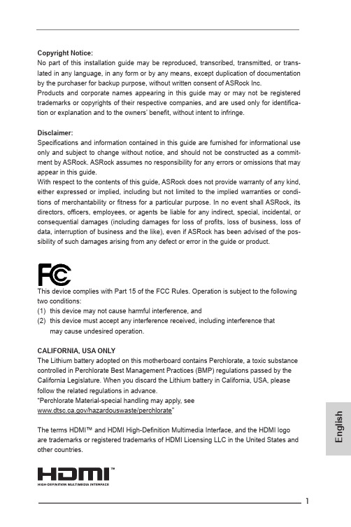
1En g l i s h Copyright Notice:No part of this installation guide may be reproduced, transcribed, transmitted, or trans-lated in any language, in any form or by any means, except duplication of documentation by the purchaser for backup purpose, without written consent of ASRock Inc.Products and corporate names appearing in this guide may or may not be registered trademarks or copyrights of their respective companies, and are used only for identifica -tion or explanation and to the owners’ benefit, without intent to infringe.Disclaimer:Specifications and information contained in this guide are furnished for informational use only and subject to change without notice, and should not be constructed as a commit-ment by ASRock. ASRock assumes no responsibility for any errors or omissions that may appear in this guide.With respect to the contents of this guide, ASRock does not provide warranty of any kind, either expressed or implied, including but not limited to the implied warranties or condi-tions of merchantability or fitness for a particular purpose. In no event shall ASRock, its directors, officers, employees, or agents be liable for any indirect, special, incidental, or consequential damages (including damages for loss of profits, loss of business, loss of data, interruption of business and the like), even if ASRock has been advised of the pos-sibility of such damages arising from any defect or error in the guide or product.This device complies with Part 15 of the FCC Rules. Operation is subject to the following two conditions:(1) this device may not cause harmful interference, and(2) this device must accept any interference received, including interference thatmay cause undesired operation.CALIFORNIA, USA ONLYThe Lithium battery adopted on this motherboard contains Perchlorate, a toxic substance controlled in Perchlorate Best Management Practices (BMP) regulations passed by the California Legislature. When you discard the Lithium battery in California, USA, please follow the related regulations in advance.“Perchlorate Material-special handling may apply, see/hazardouswaste/perchlorate”The terms HDMI™ and HDMI High-Definition Multimedia Interface, and the HDMI logo are trademarks or registered trademarks of HDMI Licensing LLC in the United States andother countries.EnglishMotherboard Layout235678910111242ASRock H61TM-ITX MotherboardASRock H61TM-ITX Motherboard 3En g l i shEnglishI/O Panel** There are two LEDs on the LAN port. Please refer to the table below for the LAN port LED indications.ACT/LINKLEDSPEEDLEDLAN PortLAN Port LED IndicationsActivity/Link LED SPEED LEDStatus Description Status DescriptionOff No Link Off10Mbps connectionBlinking Data Activity Off100Mbps connectionOn100Mbps connection Yellow1Gbps connection* Please use a 19V power adaptor for the DC jack. This jack accepts dual barrel plugs with an inner diameter of 2.5 mm and an outer diameter of 5.5 mm, where the inner contact is +8 (±10%) through +19 (±10%) VDC and the shell is GND. The maximum current rating depends on the power adaptor. The following are examples of power adaptors that may be used:DELTA DELTA-ADP-150TB-150W/19VHP HP-TBC-BA52-150W/19VFSP FSP-FSP150-ABAN1-150W/19V124536789<20mm4ASRock H61TM-ITX MotherboardASRock H61TM-ITX Motherboard 5En g l i sh 1. IntroductionThank you for purchasing ASRock H61TM-ITX motherboard, a reliable motherboard produced under ASRock’s consistently stringent quality con-trol. It delivers excellent performance with robust design conforming to AS-Rock’s commitment to quality and endurance.This Quick Installation Guide contains introduction of the motherboard. More detailed information of the motherboard can be found in the user manual presented in the Support CD.1.1 Package ContentsASRock H61TM-ITX Motherboard(Thin Mini-ITX Form Factor: 6.7-in x 6.7-in, 17.0 cm x 17.0 cm)ASRock H61TM-ITX Quick Installation GuideASRock H61TM-ITX Support CD2 x SATA Data Cables (Optional)1 x SATA 1 to 1 Power Cable (Optional)2 x I/O Panel Shields (Optional)English1.2 Specifications6ASRock H61TM-ITX MotherboardASRock H61TM-ITX Motherboard 7En g l i shEnglishCAUTION!1. Due to limitation, the actual memory size may be less than 4GBfor the reservation for system usage under Windows® 32-bitoperating systems. Windows® 64-bit operating systems do nothave such limitations. You can use ASRock XFast RAM to uti-lize the memory that Win dows® cannot use.2. PCIE3.0 is only supported with Intel® Ivy Bridge CPU. With In-tel® Sandy Bridge CPU, it only supports PCIE 2.0.3. Intel® HD Graphics Built-in Visuals and the VGA outputs can besupported only with processors which are GPU integrated. Intel®Quick Sync Video 2.0, Intel® InTru TM 3D, Intel® Clear Video HDTechnology, Intel® Insider TM, Intel® HD Graphics 2500/4000 aresupported by Intel® Ivy Bridge CPU. Intel® Quick Sync Video,Intel® InTru TM 3D, Intel® Clear Video HD Technology, Intel® HDGraphics 2000/3000, Intel® Advanced Vector Extensions (AVX)are supported by Intel® Sandy Bridge CPU.* For detailed product information, please visit our website:8ASRock H61TM-ITX MotherboardASRock H61TM-ITX Motherboard 9En g l i s h WARNINGPlease realize that there is a certain risk involved with over-clocking, including adjusting the setting in the BIOS, applyingUntied Overclocking Technology, or using third-party overclock-ing tools. Overclocking may affect your system’s stability, oreven cause damage to the components and devices of yoursystem. It should be done at your own risk and expense. We arenot responsible for possible damage caused by overclocking.10ASRock H61TM-ITX MotherboardEnglish 1.3 Pin Header Easy Installation GuideASRock motherboards are equipped with pin headers with obvious colors that assist you to recognize the crucial headers. Please refer to the illustra-tion of the onboard headers’ pin defintion below. If you need more informa -tion about the usage of these headers, please refer to “Onboard Headersand Connectors” and “Jumper Setup” for details.Front PanelAudio Header HDMI_SPDIFHeaderSystem Panel HeaderUSB 2.0 HeaderUSB 2.0 HeaderPower LED HeaderUSB 3.0 HeaderE n g l i s h1.4 Onboard Headers and ConnectorsOnboard headers and connectors are NOT jumpers. Do NOT place jumper caps over these headers and connectors. Plac-ing jumper caps over the headers and connectors will causepermanent damage to the motherboard!Serial ATA2 Connectors(SATA_0:see p.2, No. 6)(SATA_1:see p.2, No. 2)SATA_1 SATA_0These two Serial ATA2 (SATA2) connectors sup-port SATA data cables for internal storage devices. The current SATA2 interface allows up to 3.0 Gb/s data transfer rate.USB 2.0 Headers(9-pin USB4_5)(see p.2, No. 20)(9-pin USB6_7)(see p.2, No. 7)(4-pin USB8)(see p.2, No. 3)Besides two default USB 2.0 ports on the I/O panel, there are three USB 2.0 headers and one USB port on this motherboard. Each USB 2.0 header can support two USB 2.0 ports.USB 3.0 Header(19-pin USB3_0_1)(see p.2, No. 9)Besides two default USB 3.0 ports on the I/O panel, there is one USB 3.0 header on this motherboard. The USB 3.0 header can support two USB 2.0 ports.EnglishConsumer Infrared Module Header(7-pin CIR1)(see p.2, No. 5)This header can be used t o c o n n e c t t h e r e m o t e controller receiver.1GNDLearn-inIRTX+5VALED+5VACIR inputFront Panel Audio Header(9-pin HD_AUDIO1)(see p.2, No. 26)This is an interface for the front panel audio cable that allows convenient connec-tion and control of audio devices.1. High Definition Audio supports Jack Sensing, but the panel wire on the chassis must support HDA to function correctly. Please follow the instructions in our manual and chassis manual to install your system.2. If you use an AC’97 audio panel, please install it to the front panel audio header by the steps below: A. Connect Mic_IN (MIC) to MIC2_L.B. Connect Audio_R (RIN) to OUT2_R and Audio_L (LIN) to OUT2_L.C. Connect Ground (GND) to Ground (GND).D. MIC_RET and OUT_RET are for HD audio panel only. You don’t need to connect them for AC’97 audio panel.E. To activate the front mic.For Windows ® XP / XP 64-bit OS:Select “Mixer”. Select “Recorder”. Then click “FrontMic”. For Windows ®8 / 8 64-bit / 7 / 7 64-bit / Vista TM / Vista TM 64-bit OS:Go to the “FrontMic” Tab in the Realtek Control panel. Adjust “Recording Volume”.E n g l i s hSystem Panel Header(9-pin PANEL1)(see p.2, No. 12)Analog Surround Audio Header(17-pin HD_AUDIO2)(see p.2, No. 27)Connect the power switch, reset switch and system sta-tus indicator on the chassis to this header according to the pin assignments below. Note the positive and nega-tive pins before connectingthe cables.PIN Signal Name PIN Signal Name 18SENSE 17KEY 16LFE 15A_GND 14A_GND 13Center 12Surr_Rear_R 11A_GND 10A_GND 9Surr_Rear_L 8Surr_Side_R 7A_GND 6A_GND 5Surr_Side_L 4Front_R 3A_GND 2A_GND 1Front_LPower LED Header(3-pin PLED1)(see p.2, No. 11)3W Audio AMP Output Wafer Header(4-pin SPEAKER1)(see p.2, No. 28)Please connect the chassis speaker to this header.Please connect the chassis power LED to this header to indicate system power status. The LED is on when the system is operating. The LED keeps blinking in S1/S3 state. The LED is off in S4 state or S5 state (power off).Front_L+Front_R-1Front_R+Front_L-Chassis Fan Connector (4-pin CHA_FAN1) (see p.2, No. 4)Please connect a fan cable to the fan connector and match the black wire to theground pin.CPU Fan Connectors (4-pin CPU_FAN1) (see p.2, No. 22)Though this motherboard provides a 4-Pin CPU fan (Quiet Fan) connector, 3-Pin CPU fans can still work even without fan speed control. If you plan to connect a 3-Pin CPU fan, please connect itto Pin 1-3.SATA Power Connector (SATA_POW1)(see p.2, No. 10)Please connect a SATApower cable.Serial Port Header (10-pin COM1) (see p.2, No. 18)This COM1 header supports a serial port module.HDMI_SPDIF Header (2-pin HDMI_SPDIF1) (see p.2, No. 25)This header provides SPDIFaudio output to HDMI VGAcards, allowing the systemto connect HDMI DigitalTV/projector/LCD devices.Please connect the HDMI_SPDIF connector of a HDMIVGA card to this header.RTS CTSGNDTXDDCDDSRDTRRXD1NCRIEnglishE n g l i s hBacklight & Amp Volume Control Header(8-pin BLT_VOL1)(see p.2, No. 17)Digital MIC Header(5-pin DMIC1)(see p.2, No. 24)Home Theater PC Header(7-pin HTPC1)(see p.2, No. 29)1: BKLT_EN 2: BKLT_PWM 3: BKLT_PWR 4: BKLT_PWR 5: GND 6: GND7: Brightness_Up 8: Brightness_Down1: +5V 2: No pin2: SPDIF_OUT/DMIC_CLK 3: GND4: DMIC_DATA5: +3.3VPIN Signal Name PIN Signal Name 8HDMI CEC 7#Power_Button 6SMB_DATA 5 3.3V Standby 4SMB_CLK 3No pin 2GND 1Recording LEDLPC Debug Header(13-pin LPC1)(see p.2, No. 30)PIN Signal Name PIN Signal Name 14+3V 13No pin 12+3V 11+3V 10GND 9GND 8LAD37LAD26LAD15LAD04LFRAME#3RESET#2GND 1CLK11LVDS Panel Connector (40-pin LVDS1)(see p.2, No. 15)PIN Signal Name PIN Signal Name1ODD_Lane3_P21NC2ODD_Lane3_N22EDID_3.3V3ODD_Lane2_P23LCD_GND4ODD_Lane2_N24LCD_GND5ODD_Lane1_P25LCD_GND6ODD_Lane1_N26ODD_CLK_P7ODD_Lane0_P27ODD_CLK_N8ODD_Lane0_N28BKLT_GND9EVEN_Lane3_P29BKLT_GND10EVEN_Lane3_N30BKLT_GND11EVEN_Lane2_P31EDID_CLK12EVEN_Lane2_N32BKLT_ENABLE13EVEN_Lane1_P33BKLT_PWM_DIM14EVEN_Lane1_N34EVEN_CLK_P15EVEN_Lane0_P35EVEN_CLK_N16EVEN_Lane0_N 36BKLT_PWR (12V/19V)17EDID_GND 37BKLT_PWR (12V/19V)18LCD_VCC (3.3V/5V/12V)38BKLT_PWR (12V/19V)19LCD_VCC (3.3V/5V/12V)39NC20LCD_VCC (3.3V/5V/12V)40EDID_DATA140EnglishE n g l i s hClear CMOS Jumper(CLRCMOS1)(see p.2, No. 31)Clear CMOSDefaultCLRCMOS1 allows you to clear the data in CMOS. To clear and reset the system parameters to default setup, please turn off the computer and unplug the power cord from the power supply. After waiting for 15 seconds, use a jumper cap to short pin2 and pin3 on CLRCMOS1 for 5 seconds. However, please do not clear the CMOS right after you update the BIOS. If you need to clear the CMOS when you just finish updating the BIOS, you must boot up the system first, and then shut it down before you do the clear-CMOS action. Please be noted that the password, date, time, user default profile, 1394 GUID and MAC address will be cleared only if the CMOS battery is removed.1.5 Jumper SetupWhen the jumper cap is placed on the pins, the jumper is “Short”. If no jumper cap is placed on the pins, the jumper is “Open”. The illustration shows a 3-pin jumper whose pin1 and pin2 are “Short” when a jumper cap is placed on these2 pins.Backlight Power Jumper(3-pin BKT_PWR1)(see p.2, No. 13)1-2 : +19V 2-3 : +12VPanel Power Jumper(3-pin PNL_PWR1)(see p.2, No. 14)1-2 : +3V 2-3 : +5V2. BIOS InformationThe Flash Memory on the motherboard stores the BIOS Setup Utility.When you start up the computer, please press <F2> or <Del> during thePower-On-Self-Test (POST) to enter the BIOS Setup utility; otherwise,POST continues with its test routines. If you wish to enter BIOS Setup afterPOST, please restart the system by pressing <Ctl> + <Alt> + <Delete>, orpressing the reset button on the system chassis. The BIOS Setup programis designed to be user-friendly. It is a menu-driven program, which allowsyou to scroll through its various sub-menus and to select among the prede-termined choices. For detailed information about BIOS Setup, please referto the User Manual (PDF file) contained in the Support CD.3. Software Support CD informationThis motherboard supports various Microsoft® Windows® operating sys-tems: 8 / 8 64-bit / 7 / 7 64-bit / Vista TM / Vista TM 64-bit / XP / XP 64-bit. TheSupport CD that came with the motherboard contains necessary driversand useful utilities that will enhance motherboard features. To begin usingthe Support CD, insert the CD into your CD-ROM drive. It will display theMain Menu automatically if “AUTORUN” is enabled in your computer. If theMain Menu does not appear automatically, locate and double-click the file“ASRSETUP.EXE” in the Support CD to display the menu. EnglishF r a n ça i s D e u t s c hSpezifikationenDeutschF r a n ça i s De u t s c h * Für die ausführliche Produktinformation, besuchen Sie bitte unsereWebsite: FrançaisFr a n ça is* Pour de plus amples informations sur les produits, s’il vous plaît visiteznotre site web: FrançaisIt a l i a n oItalianoIt a l i a n o * Per ulteriori informazioni, prego visitare il nostro sito internet:EspañolEs p a ñol* Para más información sobre los productos, por favor visite nuestro sitioweb: EspañolРусскийСпецификацииРусскийРусский * Для детальной информации продукта, пожалуйста посетите наш вебсайт:PortuguêsPo r t u g u êsPortuguês* Para informações mais detalhadas por favor visite o nosso sítio Web: Tür k çeÖzelliklerTürkçe* Ayrıntılı ürün bilgileri için lütfen web sitemizi ziyaret edin:eçkrüT한 국 어설명서한국어* 상세한 제품정보는 당사의 웹사이트를 방문할수있습니다.한 국 어日本語仕様日本語日本語 * 製品の詳細については、を御覧なさい。
mini_itx_spec_V1_1
Mini-ITX Addendum Version 1.1 To the microATX Motherboard Interface Specification Version 1.2 April 20091. INTEL CORPORATION (“INTEL”) MAKES NO WARRANTIES WITH REGARD TO THISSPECIFICATION (“SPECIFICATION”), AND IN PARTICULAR DOES NOT WARRANT ORREPRESENT THAT THIS SPECIFICATION OR ANY PRODUCTS MADE INCONFORMANCE WITH IT WILL WORK IN THE INTENDED MANNER. NOR DOESINTEL ASSUME RESPONSIBILITY FOR ANY ERRORS THAT THE SPECIFICATIONMAY CONTAIN OR HAVE ANY LIABILITIES OR OBLIGATIONS FOR DAMAGESINCLUDING, BUT NOT LIMITED TO, SPECIAL, INCIDENTAL, INDIRECT, PUNITIVE,OR CONSEQUENTIAL DAMAGES WHETHER ARISING FROM OR IN CONNECTIONWITH THE USE OFTHIS SPECIFICATION IN ANY WAY.2.NO REPRESENTATIONS OR WARRANTIES ARE MADE THAT ANY PRODUCTBASED IN WHOLE OR IN PART ON THE ABOVE SPECIFICATION WILL BE FREE FROMDEFECTS OR SAFE FOR USE FOR ITS INTENDED PURPOSE. ANY PERSON MAKING,USING OR SELLING SUCH PRODUCT DOES SO AT HIS OR HER OWN RISK.3. THE USER OF THIS SPECIFICATION HEREBY EXPRESSLY ACKNOWLEDGES THATTHE SPECIFICATION IS PROVIDED AS IS, AND THAT INTEL MAKES NOREPRESENTATIONS, EXTENDS NO WARRANTIES OF ANY KIND, EITHER EXPRESSOR IMPLIED, ORAL OR WRITTEN, INCLUDING ANY WARRANTY OFMERCHANTABILITY OR FITNESS FOR A PARTICULAR PURPOSE, OR WARRANTY ORREPRESENTATION THAT THE SPECIFICATION OR ANY PRODUCT OR TECHNOLOGYUTILIZING THE SPECIFICATION OR ANY SUBSET OF THE SPECIFICATION WILL BEFREE FROM ANY CLAIMS OF INFRINGEMENT OF ANY INTELLECTUAL PROPERTY,INCLUDING PATENTS, COPYRIGHT AND TRADE SECRETS NOR DOES INTELASSUME ANY OTHER RESPONSIBILITIES WHATSOEVER WITH RESPECT TO THESPECIFICATION OR SUCH PRODUCTS.4.YOU MAY COPY AND REPRODUCE THIS SPECIFICATION FOR ANY PURPOSEPROVIDED THIS “IMPORTANT INFORMATION AND DISCLAIMERS” SECTION(PARAGRAPHS 1-4) IS PROVIDED IN WHOLE ON ANY COPIES YOUR MAKE. . NOOTHER LICENSE, EXPRESS OR IMPLIED, BY ESTOPPEL OR OTHERWISE, TO ANYOTHER INTELLECTUAL PROPERTY RIGHTS IS GRANTED HEREIN.Intel is a trademark of Intel Corporation in the U.S. and other countries.* Other names and brands may be claimed as the property of others. Copyright ®2009 Intel Corporation2Contents1Executive Summary (5)1.1Terminology (6)1.2Reference Documents (6)1.3Benefits to Users (6)1.4Benefits to Manufacturers (6)2Layout (7)2.1Board dimensions (8)2.2Mounting Hole Placement (8)2.3Connector placement (10)2.4Height Constraints (10)2.4.1Primary (Component) Side Height Constraints (10)2.4.2Secondary (Bottom/Solder) Side Height Constraints (11)3Power Supply Information (12)FiguresFigure 1. Example Mini-ITX Layout (7)Figure 2. ATX, microATX, and Mini-ITX Mounting Holes (8)Figure 3. Mini-ITX Board Diagram (9)Figure 4. Mini-ITX Maximum Component Height Restrictions (10)TablesTable 1. Mini-ITX Addendum Feature Summary (5)Table 2. Compares ATX, microATX, and Mini-ITX board dimensions (8)Table 3. Motherboard Mounting Hole Locations (9)3Revision History§ 41Executive SummaryThe Mini-ITX addendum to the microATX Motherboard Interface Specification detailsthe use of the Mini-ITX form factor standard, developed by Via Technologies Inc, forcompatibility with Intel based platforms. This document defines only the specificfeatures in Intel’s Mini-ITX based platforms that differ from those of microATX andshould be used in conjunction with the governing microATX specification.A smaller motherboard layout offers system developers the ability to create new andinnovative system designs. This smaller version of microATX allows and encouragesdevelopers to build within the sub 8 Liter chassis volume for a variety of newapplications.Described within this document are requirements and characteristics of a Mini-ITXmotherboard, so that a motherboard may function and fit appropriately when pairedwith a Mini-ITX chassis. Beyond this, it does not detail processor, memory, graphicsor other system features required to meet the Mini-ITX form factor. These items areleft to system designers and integrators within the guidelines of the microATXspecification.Table 1. Mini-ITX Addendum Feature SummaryThis addendum does NOT define:•Specific power supply form factors•Thermal design guidance to chassis vendors (covered in TASC guide listed in Reference Documents)The Mini-ITX addendum to the microATX Specification is a public document intendedfor widespread application in many types of systems. It is available through a publicwebsite located at:51.1Terminology1.2Reference DocumentsThe following reference documents are posted on the public web site at1.3Benefits to UsersTrends in the industry indicate that users require a smaller and lower cost solution fortheir PC needs. The smaller board size and lower height keep out zones enable areduced sized chassis as it sits on the user’s desk, is mounted on a display, or comesin any other innovative form factor. These changes also enable a PC to be designedinto various aesthetic shapes and sizes.1.4Benefits to ManufacturersBy manufacturing to this Mini-ITX specification, motherboard manufacturers andchassis manufacturers can guarantee a better compatibility between their products.They can also capitalize on the benefits of a reduction in total system costs because ofa reduced system size. This specification allows chassis vendors to design theirproduct targeting the soldered down, low power processors all the way up to highperformance, multi-core processors. It eliminates the need for them to designtargeted chassis for each platform.§62LayoutThis section describes the mechanical specification of the Mini-ITX form-factormotherboard. Size, mounting hole placement, connector placement, and componentheight constraints are specified. System components such as hard drives, disk drives,and power supplies are not specified, however it is generally recommended toconsider what would facilitate assembly, as well as not place components such thatthey block fan inlets. An example layout is depicted in Figure 1.Figure 1. Example Mini-ITX LayoutNote: Depicted system is approximately 8L with standard desktop components.72.1Board dimensionsTable 2. Compares ATX, microATX, and Mini-ITX board dimensions2.2Mounting Hole PlacementMini-ITX utilizes a subset of ATX mounting holes. To avoid damage to traces onmotherboards, chassis standoffs in any locations not specified should be removable ornot implemented at all. See Figure 2 for relative hole location compared to ATX andmicroATX motherboards.Figure 2. ATX, microATX, and Mini-ITX Mounting HolesNOTE:Board is shown oriented with the rear of the board towards the top.NOTE:The lighter portion indicates the approximate region of the Mini-ITX form factor.8Table 3. Motherboard Mounting Hole LocationsFigure 3. Mini-ITX Board Diagram92.3Connector placementAll connector locations as well as allowable placement area for I/O connectors on theback panel are described and can be found in the microATX interface specification. 2.4Height Constraints2.4.1Primary (Component) Side Height ConstraintsOne major advantages of the Mini-ITX form factor is its backward-compatibility withthe ATX specification. The Mini-ITX motherboard can be installed in any ATX chassis.Figure 4 shows the required maximum component height constraints for thecomponents on the PC board. For full compliance with Mini-ITX, and to preventinterference with the chassis structure, power supply, or peripherals, the motherboardcomponents should not exceed the height limit in each zone defined. Similarly,compliant power supplies, peripherals, and chassis features should not extend into themotherboard component area.Figure 4. Mini-ITX Maximum Component Height Restrictions10Notes:•All dimensions in the above figure are in millimeters (mm).•The 57mm height restriction in Area A applies to the PC board componentheight. The actual height of the chassis should include any dynamic excursionconsiderations for shipping as well as needs to facilitate alternative coolingsolutions or airflow considerations.•For Intel boxed processor fan heat sink, it is strongly recommended not toplace components between fan inlet and chassis side vent by leaving spacebetween chassis wall and area A open.•The component height requirement assumes a motherboard thickness of 1.57 mm (0.062”).2.4.2Secondary (Bottom/Solder) Side Height ConstraintsNo height restraints on secondary side are added or removed from what isspecified in the microATX Motherboard Interface Specification.113Power Supply InformationProvided the very different needs of the platforms that fit in the small desktop formcategory, this specification does not attempt to define a standard for the power supplyto match with the Mini-ITX motherboard specification. Instead it recommends thatmanufacturers consider using a:•SFX, TFX or FlexATX are available power supply form factor for chassisgreater than 5 liters•External power adapter for chassis less than 5 litersRefer to the microATX Motherboard interface Specification for information on powersupply requirements.12。
电脑主板选购指南ATXMicroATXMiniITX的比较

电脑主板选购指南ATXMicroATXMiniITX的比较作为电脑硬件中至关重要的组成部分,主板的选择对于电脑系统功能和性能的发挥至关重要。
而在众多主板规格中,ATX、MicroATX和MiniITX是三种最为常见的规格,今天我将为大家详细比较这三种主板规格的优缺点,以帮助大家更好地选择适合自己需求的主板。
1.ATX主板ATX主板是最常见的主板规格,也是最大的。
它通常具有最多的扩展插槽,能够容纳更多的显卡、内存和存储器。
ATX主板的尺寸为305mm×244mm,最多有7个扩展插槽,适合那些需要高扩展性和大型机箱的用户。
优点:- 更多的扩展插槽:适合高性能需求,能够容纳多个显卡、内存和存储器,提供更丰富的接口。
- 散热更好:ATX主板尺寸大,散热更好,兼容性较好,能更好地搭配高性能硬件组合。
缺点:- 尺寸较大:体积庞大,适用于大型机箱,对于需要便携性的用户不太友好。
- 成本相对较高:ATX主板通常价格较高,需要更高的预算。
2.MicroATX主板MicroATX主板是ATX主板的缩小版本,尺寸为244mm×244mm。
虽然相对于ATX主板而言,扩展插槽较少,但性能方面并不逊色。
优点:- 更小的尺寸:适合一般大小的机箱,更加方便携带和安装,省空间。
- 性价比高:价格相对ATX主板较低,适合那些对于扩展能力要求不高的用户。
缺点:- 较少的扩展插槽:有限的扩展插槽限制了硬件升级和扩展的能力,不太适合追求高性能的用户。
3.MiniITX主板MiniITX主板是目前最小的主板规格,尺寸仅为170mm×170mm。
虽然尺寸小,但它也有着自身的独特优势。
优点:- 超小尺寸:适合小型机箱或者不限于传统机箱的DIY用户,能够满足追求小巧的需求。
- 节省空间:适用于有空间限制的场所,如电视柜、办公桌等。
缺点:- 扩展性差:MiniITX主板通常只有一个扩展插槽,无法容纳太多硬件组件,追求高性能的用户需要慎重考虑。
了解电脑主板的不同型号及其功能

了解电脑主板的不同型号及其功能电脑主板(Motherboard)是计算机硬件中最核心的部件之一,它连接了所有其他硬件组件并负责它们之间的通信和协调。
不同的电脑主板型号拥有不同的功能和特点,这决定了计算机的性能和扩展能力。
本文将探讨几种常见的电脑主板型号及其功能特点。
一、ATX主板ATX(Advanced Technology Extended)是一种较为普遍的电脑主板标准。
ATX主板通常有较大的尺寸,适用于桌面计算机的组装。
ATX主板的主要特点包括以下几个方面:1. 扩展插槽:ATX主板通常提供多个PCI插槽和PCIe插槽,用于安装显卡、声卡、网卡等扩展设备,提供更好的扩展性。
2. 内存插槽:ATX主板通常拥有多个内存插槽,支持较大容量的内存,提供更好的运行性能。
3. 后置接口:ATX主板通常提供多个后置接口,包括USB、音频、网口等,方便用户连接外部设备。
4. 电源接口:ATX主板采用标准的24pin电源接口,提供稳定的电源供应。
二、Mini-ITX主板Mini-ITX主板是一种小型化的电脑主板,适用于小型计算机系统,如HTPC(家庭影音娱乐中心),小型服务器等。
Mini-ITX主板的主要特点如下:1. 尺寸小巧:Mini-ITX主板尺寸通常为17x17厘米,比ATX主板更小,适用于空间有限的环境。
2. 扩展插槽:由于尺寸限制,Mini-ITX主板通常只提供一个PCIe 插槽和一到两个内存插槽,扩展性有限。
3. 低功耗:Mini-ITX主板通常采用低功耗的物理构造和组件,适用于需要长时间稳定运行的场景。
4. 多媒体功能:由于适用于家庭影音娱乐中心等场景,Mini-ITX主板通常具备多媒体功能,包括高清视频输出、音频输出等。
三、Micro-ATX主板Micro-ATX主板是一种介于ATX和Mini-ITX之间的主板标准,主要特点如下:1. 尺寸中等:Micro-ATX主板的尺寸介于ATX和Mini-ITX之间,适用于中等尺寸的计算机系统。
主板分类
电脑主板分几种?按大小分,分为小板(MicroATX)、大板(A TX)、迷你板(Mini ATX);按是否集成显示芯片分,分为集成显示芯片主板和无集成显示芯片主板;还有一种特殊主板:ITX主板---集成了CPU、显卡的迷你型整合主板。
电脑主板分哪几种型号啊?主板,又叫主机板(mainboard)、系统板(systembourd)和母板(motherboard);它安装在机箱内,是微机最基本的也是最重要的部件之一。
主板一般为矩形电路板,上面安装了组成计算机的主要电路系统,一般有BIOS芯片、I/O控制芯片、键盘和面板控制开关接口、指示灯插接件、扩充插槽、主板及插卡的直流电源供电接插件等元件。
主板的另一特点,是采用了开放式结构。
主板上大都有6-8个扩展插槽,供PC机外围设备的控制卡(适配器)插接。
通过更换这些插卡,可以对微机的相应子系统进行局部升级,使厂家和用户在配置机型方面有更大的灵活性。
总之,主板在整个微机系统中扮演着举足重新的脚色。
可以说,主板的类型和档次决定着整个微机系统的类型和档次,主板的性能影响着整个微机系统的性能。
常见的PC机主板的分类方式有以下几种★主板的分类:一、按主板上使用的CPU分有:386主板、486主板、奔腾(Pentium,即586)主板、高能奔腾(Pentium Pro,即686)主板。
同一级的CPU往往也还有进一步的划分,如奔腾主板,就有是否支持多能奔腾(P55C,MMX要求主板内建双电压),是否支持Cyrix 6x86、AMD 5k86 (都是奔腾级的CPU,要求主板有更好的散热性)等区别。
二、按主板上I/O总线的类型分·ISA(Industry Standard Architecture)工业标准体系结构总线.·EISA(Extension Industry Standard Architecture)扩展标准体系结构总线.·MCA(Micro Channel)微通道总线. 此外,为了解决CPU与高速外设之间传输速度慢的"瓶颈"问题,出现了两种局部总线,它们是:·VESA(Video Electronic Standards Association)视频电子标准协会局部总线,简称VL 总线.·PCI(Peripheral Component Interconnect)外围部件互连局部总线,简称PCI总线. 486级的主板多采用VL总线,而奔腾主板多采用PCI总线。
小主板

小巧精致高性能主流ITX小主板推荐2009-5-7 14:40:28 文/Tim,编辑:陈天韵出处:(IT世界网)对于不少的电脑玩家都应该知道mini ITX主板,在VIA大力推动下mini ITX规格在市场上已经存在一段很长的时间,VIA可以说是mini ITX的始祖,此后VIA更推出了规格更小的ITX规格。
市场上的mini ITX主板多数针对工控用户已经一些机顶盒用户,所以在零售市场上比较少见,而且配置一般都比较低,如果想找到比较好的ITX主板只有在二手市场里面寻找。
自从Intel推出ATOM处理器后,Intel将ATOM和945芯片组打包销售,自家推出了ITX规格的ATOM平台,又一次将ITX带到了主流市场,集成CPU的ATOM主板用户只需要配上内存,硬盘和电源就变成一套电脑了,而且功耗要比一般的台式机低很多,虽然性能并不算十分出色,但对于时常需要下载及文件共享的用户是一个相当理想的选择。
而不少的厂商都有推出可以更换CPU或者使用其他CPU的ITX主板,一般都包括现有的Intel的LGA775和AMD的AM2平台的产品。
Mini-ITX是由威盛电子主推的主板规格。
Mini-ITX主板能用于microATX或ATX机箱,尺寸为17 x 17厘米,刚刚好能包括四颗固定螺丝和一条扩充插槽。
由于扩充性不大,Mini-ITX 主要用于嵌入式系统。
英特尔亦有推出使用 Mini-ITX 规格的桌面系统主板,尺寸为171.45mmx 171.45mm,但在网页上标示为“uATX”而非 Mini-ITX。
ITX主板相对于普通的ATX和mATX主板要小巧的多,而且功能也相当齐全。
集成CPU 的ITX主板可以大大降低平台的组建成本,以Intel集成ATOM的ITX主板为例,主板售价499元,加上2G的内存大概150元,电源大概150元左右,对于不同用户对硬盘要求不同如果是下载用户配上1TB的硬盘599元整个平台造价为1398元,远远要比组装一台低价的电脑要便宜很多,而且价格可能要比市面上售卖的1TB的NAS还便宜,功能要比NAS更为强大。
A1876主板解析

A1876主板解析市面上有ATX、MATX、μATX、ITX、XL-ATX、MiniATX、FlexATX、E-ATX、EE-ATX、HPTX及WTX等等一系列的主板版型,说多不多,说少还真不少,就连子凡我这个专业人员来说有时候都有些混乱,所以为了便于记忆,我们可以按照分类及大小为大家梳理了一下这些板型内在的联系,我们一起看看吧。
主板分类:大板:ATX、MiniATX、XL-ATX、非标准E-ATX小板:MATX、μATX、FlexATX迷你板:ITX(包括Thin-ITX)超大板:标准E-ATX、EE-ATX、HPTX、WTX主板尺寸:最小的是ITX主板(170mm*170mm)中不溜的是MATX主板(244mm*244mm)MATX主板宽度砍掉一块,变成μATX主板(244mm*185mm)MATX主板长宽各砍掉一块,变成FlexATX主板(229mm*191mm)大的是ATX主板(305mm*244mm)ATX长宽各砍掉一块,变成MiniATX主板(284mm*208mm)ATX主板加长,变成XL-ATX主板(343mm*262mm)ATX主板加宽,变成E-ATX主板(305mm*330mm)E-ATX主板加长,变成EE-ATX主板(347mm*330mm)EE-ATX主板加宽,变成HPTX主板(345mm*381mm)HPTX主板加宽,变成WTX主板(356mm*425mm)板型的分类尚且如此复杂,更不要体积诸多主板厂商由于种种原因所推出的“形态各异”的“个性产品”。
那么究竟怎样才能把握好主板的板型来选择合适的机箱呢?那就是主板螺丝孔间的孔距。
通过主板孔距示意图我们可以清楚的看到,纵使主板的长宽如何被主板制造商修改,它也必须遵守PC行业的规范——孔距便是其中之一。
一类板型所使用的螺丝孔是固定的,如μATX与MiniATX,它们的主板宽度相似,因此使用两列螺丝孔,只是由于长度的不同,μATX使用两排螺丝孔,而MiniATX使用三排;又如MATX与ATX,因此两种板型均使用三列螺丝,只是由于前者仅仅是在长度上短于后者,所以MATX使用三排螺丝,而ATX使用四排螺丝。
七彩虹 主板 说明书
CMOS 清除: JBAT ···················································12 键盘开机跳线选择:JKB ···········································13 2-4 连接器和引脚连接头 ··············································13 2-4-1 连接器 ·························································13 电源连接器(24 引脚) : ATXPWR··································13 ATX 12V 电源连接器(4 引脚) : PWR12V ························14 PS/2 鼠标和 PS/2 键盘连接器: PS2 ······························15 USB 端口连接器: R_USB1 ·········································15 LAN 端口连接器: USB_LAN1 ······································15 音频输入、输出、麦克风、环绕输出、中置低音炮输出、侧边 环绕输出:AUDIO1 ·················································16 2-4-2 引脚连接头 ···················································20 第三章驱动程序安装说明 ·············································28 第四章 BIOS 设置 ······················································30 4-1 进入 BIOS 主界面··················································31 4-2 BIOS 主界面························································34 4-3 标准 COMS 设定(Standard CMOS Features) ··················35 Date(日期) ························································35 Time(时间) ·······················································36 IDE Channel 0/1/2 Master/Slave (IDE 第 1/2/3 主/从通道) ·········································································36 Drive A/Drive B (软盘类型的设置) ·······························36
主板参数详解 (3)

主板参数详解1. 引言主板(Motherboard)是计算机重要组成部分之一,它承载了CPU、内存、扩展卡等重要硬件设备。
主板的参数决定了计算机的性能和功能,下面将详细介绍主板的各个参数。
2. 主板尺寸主板尺寸是主板参数中比较重要的一个方面,不同尺寸的主板适用于不同的机箱。
常见的主板尺寸有ATX、Micro ATX 和Mini ITX等,其中ATX尺寸(305mm × 244mm)的主板最为常见。
3. CPU插槽类型主板上的CPU插槽对于选择适配的CPU非常重要。
常见的CPU插槽类型有LGA和PGA两种,其中LGA类型的插槽为插针设计,而PGA类型的插槽则是针脚设计。
4. 内存插槽类型内存插槽类型决定了主板支持的内存条类型。
常见的内存插槽类型有DDR3和DDR4两种。
DDR4插槽能够提供更高的频率和更低的能耗,因此在性能上更具优势。
5. 扩展插槽主板上的扩展插槽是连接扩展卡的重要通道。
常见的扩展插槽有PCI-E和PCI插槽,其中PCI-E插槽是目前最新的扩展接口,具有更高的传输速度和更低的延迟。
6. 主板芯片组主板芯片组是主板关键的控制中心,它负责管理和协调主板上的各种硬件设备。
常见的主板芯片组有Intel和AMD两种,其中Intel芯片组兼容性好,稳定性较高。
7. 显卡插槽类型显卡插槽类型决定了主板支持的显卡类型。
常见的显卡插槽有PCI-E和AGP两种,其中PCI-E插槽是目前流行的显卡接口,支持更高的带宽和更多的显存。
8. 存储接口存储接口是连接硬盘和固态硬盘的接口。
常见的存储接口有SATA和NVMe两种,其中SATA接口是目前主流的存储接口,而NVMe接口具有更快的传输速度和更低的延迟。
9. 后置IO接口后置IO接口是主板背面提供的各类接口,用于连接外部设备。
常见的后置IO接口有USB、音频接口、网口等,这些接口的数量和类型直接影响了计算机的扩展性和连接设备的便利程度。
10. BIOS和UEFIBIOS(Basic Input/Output System)和UEFI(Unified Extensible Firmware Interface)是主板固件的两种不同类型。
迷你电脑小钢炮 你真懂吗
迷你电脑小钢炮你真懂吗作者:超载来源:《电脑爱好者》2021年第03期关于游戏型迷你电脑的搭配,大家可以参考本刊2020年第24期的《与游戏主机试比高小型游戏电脑不简单》一文。
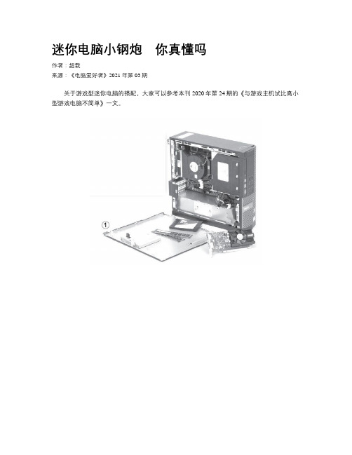
其实,品牌机应当是走出第一步的电脑类产品,不知道大家注意到没有,目前主流的品牌台式机,其实都已经变成基于MATX规格的产品,更有甚者是ITX规格,甚至一些超小的SFF(注:Small Form Factor即超小体积电脑)电脑仅有1升体积(图1)。
而以往传统的ATX规格,大多存在于高端或游戏型产品中了。
可是,这些超小规格的电脑究竟如何搭配选择,如何才能拥有一台超迷你电脑,这还真需要下一番功夫,今天笔者就将这些可能遇到的问题——分享给大家。
迷你电脑最大的特色当然就是对体积的限制性要求较高,这不仅仅考验用户的动手能力,同时也注重对设备搭配选择的经验认知。
当你决定要拥有一台迷你型电脑的时候,第一件事,就是确定它的尺寸。
这其中,机箱无疑成为第一步的选择,因为只有确定了机箱尺寸,你才能知道下一步的规划该如何制订执行。
这其中,选择MicroATX(以下简称MATX)还是ITX就成为了前提条件(图2)。
MATX主板标准于1997年12月由英特尔推出,大小是9.6英寸×9.6英寸,也就是244mm×244mm。
它的长度比标准ATX短20%(ATX标准大小为12英寸×9.6英寸)。
由于长度减少,扩充槽由ATX最多7条减少到4条。
当然,它的安装固定孔位“兼容”ATX规格,所以安装不成问题。
值得注意的事,MATX规格的主板还有一些变种尺寸,例如比较极端特殊的188mm×191mm、170mm×190mm规格,它们看起来非常接近ITX,但是同样属于MATX范畴。
ITX主板标准是由威盛在2001年提出的,它的标准尺寸为170mm×170mm(6.75英寸×6_75英寸),一开始ITX主板只用于不追求性能,集成度极高主板,例如工业设备里的电脑主板等(工控机、广告机等)。
ITX 系列 说明书
ITX系列用户手册你现选用的产品型号为:Rev:1.3Date:2009.04安全指导商标声明所有的品牌,产品,徽标,商标和公司名称都是属于商标或注册商标各自的拥有者。
AMI®是AMI 公司的注册商标。
Intel ® ,Celeron ® ,Pentium ®是 Intel 公司的注册商标。
Netware ®是Novell Inc.的注册商标。
PS/2 和 OS/2 是International Business Machines 公司的注册商标。
Windows ®98/ 2000/NT/XP 和Microsoft ®是Microsoft 公司的注册商标。
01. 务必请仔细通读本安全指导.02. 务必请妥善保管本手册,以备将来参考.03. 请保持本设备的干燥.04. 机箱的开口缝隙是用于通风避免机箱内的部件过热,请勿将此类开口掩盖或堵塞.05. 在将本设备与电源连接前,请确认电源电压值,将电压调整为110V/220V.06. 请将电源置于不会被践踏到的地方,并且不要在电源线上堆置任何实物.07. 插拔任何扩展卡或设备模块前,请将电源线拔下.08. 请留意手册上提到的所有注意和警告事项.09. 通电之前请确认主机箱中不要遗留螺丝等金属物件,以免电气短路烧毁其他部件.10.不得将任何液体倒入机箱开口的缝隙中,否则会产生严重损坏或电路瘫痪.11.如果发生以下情况,请找专业人员处理:v 电源线或插头损坏v 液体渗入机器内v 机器暴露在潮湿的环境中v 机器工作不正常或用户不能通过本手册的指导使其正常工作v 机器跌落或受创v 机器有明显的破损迹象目录安全指导......................................................................2商标声明......................................................................2第一章 主板简介及规格说明 (4)1.1 包装盒内物品清单.........................................................................................41.2 主板LAYOUT 图及规格表. (5)第二章 硬件设备的安装说明 (27)2.1 中央处理器的安装........................................................................................272.2 CPU 风扇的安装........................................................................................282.3 内存的安装...................................................................................................302.4 主板跳线的设定说明.....................................................................................312.5 主机板接头说明 (32)第三章 BIOS 简介 (42)3.1 B IOS 升级更新..............................................................................................423.2 B IOS 设定.....................................................................................................433.3 B IOS 语言切换. (43)第四章 驱动程序的安装 (44)4. 1 芯片组驱动程序的安装...............................................................................444. 2 板载显卡驱动的安装...................................................................................444. 3 板载网卡驱动的安装...................................................................................444. 4 板载声卡驱动的安装...................................................................................444. 5 USB2. 0驱动程序的安装. (44)第一章 主板简介及规格说明谢谢您采用了我司的ITX 系列主板,为了保证产品品质并适合市场需求,主板都通过了抗老化、低电压、各种温度、湿度环境下的反复测试,均能满足行业的需求。
ASRock H61M-ITX Motherboard 说明书

142ASRock H61M-ITX Motherboard1. 主板簡介謝謝你采用了華擎H61M -I T X 主板,本主板由華擎嚴格制造,質量可靠,穩定性好,能夠獲得卓越的性能。
本安裝指南介紹了安裝主板的步驟。
更加詳細的主板信息可參看驅動光盤的用戶手冊。
1.1包裝盒內物品華擎H61M-ITX 主板 (Mini-ITX 規格: 6.7英吋 X 6.7英吋, 17.0厘米 X 17.0厘米)華擎H61M-ITX 快速安裝指南華擎H61M-ITX 支持光盤兩條Serial ATA(SATA)數據線(選配)一條3.5mm 音頻線(選配)一塊I/O擋板ASRock提醒您...為了在 Windows ®7 / 7 64-bit / Vista TM / Vista TM 64-bit 系統中取得更好的性能,建議您在BIOS中將Storage Configuration(存儲配置)選項設成AHCI模式。
關于BIOS設置程序,請參見支持光盤中的“User Manual”以了解相詳細信息。
簡體中文143ASRock H61M-ITX Motherboard簡體中文1.2主板規格架构 - Mini-ITX 規格:6.7英吋 X 6.7英吋, 17.0厘米 X 17.0厘米- 全固態電容設計 (100%日本原裝高品質高傳導固態電容)處理器 - 支持第三代和二代Intel ® Core TMi7 / i5 / i3處理器 (LGA1155針腳)- 支持Intel ®Turbo Boost 2.0技術- 支持K-系列解鎖的CPU- 支持 Hyper-Threading 超線程技術(詳見警告1)芯片組 - Intel ®H61- 支持Intel ®快速啟動技術和Intel ®智能連接技術 系統內存 - 支持雙通道DDR3內存技術(見警告2) - 配備2個DDR3 DIMM 插槽- 支持DDR3 1600/1333/1066 non-ECC、un-buffered 內存(Intel ® Ivy Bridge CPU 支持DDR3 1600,Intel ®Sandy Bridge CPU 支持DDR3 1333 )- 最高支持16GB 系統容量(見警告3)- 通過Intel ® Ivy Bridge CPU 支持Intel ®Extreme MemoryProfile(XMP)1.3/1.2擴展插槽 - 1 x PCI Express 3.0 x16插槽 (藍色@ x16模式)*使用Intel ®Ivy Bridge CPU 方可支持PCIE 3.0。
- 1、下载文档前请自行甄别文档内容的完整性,平台不提供额外的编辑、内容补充、找答案等附加服务。
- 2、"仅部分预览"的文档,不可在线预览部分如存在完整性等问题,可反馈申请退款(可完整预览的文档不适用该条件!)。
- 3、如文档侵犯您的权益,请联系客服反馈,我们会尽快为您处理(人工客服工作时间:9:00-18:30)。
1.3.Thin mini ITX Motherboard 规格 a.厚度比标准的Mini-ITX小43%,Thin Mini-ITX在标准17mmx 17mm的Mini-ITX外形尺寸基础上,增加一个额外的2.5厘米I/O挡 板高度限制,其它的特点还包括外部电源供应优化,CPU插槽的 位置和SO-DIMM内存整合,以变更有效运用电源供应来产生最大 的性能. 如下图:
Thin mini ITX Motherboard 应用示意图
1.2、Thin mini ITX 平台用于介绍 Thin mini ITX Motherboard 在AIO 应用比较广泛,这种Thin Mini-ITX Motherboard 已经推动了桌面平台的转换,它的标准 建立在标准的散热风扇和25毫米的主板以及标准的I/O背板, 这个平台桌面已经成为现代PC 行业一种主流的整合。
b. 标准的一体机平台由以下部件组件: Thin mini ITX Motherboard 、Standard thermal 风扇、Touch display 、内置Speake、整合WIFI+BT模块、Digital display、 USB3.0和内置数字DIMC a.Thin mini ITX Motherboard 则需要由CPU、Memory (SODDR3)、CD-ROM、HDD这几大件组成了一体机。
Digital Microphone (数字麦克风) 数字麦克风图示和信号定义
USB 接口 a.Thin mini ITX Board 内置Single USB 2.0接口被用于设备的 摄像头,读卡器,触摸屏、USB 设备等。 B 接口有USB 2.0和USB 3.0 B 2.0 理论速率为480Mbps 即60MB/S, 但实际一般大概 在30MB/S. USB 3.0 理论速率为5Gbps 即640MB/S,但实际达不到这个速 度。 B 接口有Front USB 2.0 /3.0 接口 区分,使用线材也不 同。
海外部內部訓練教材
Thank you for your participation!
海外部內部訓練教材
Thin mini ITX Motherboard Introduce
一、Thin Mini ITX Motherboard 简介
1.1 、Thin mini ITX motherbaord 用途: 参考Intel Thin mini ITX 设计规范 A. All In One (AIO) B. Stackable home theater PC to be size compatible with the standard width of AV components such as DVD players and receivers . C. VESA mountable Thin PC D. Digital signage PC
LVDS 接口图示
40-Pin LVDS Header 信号输出
40-Pin LVDS Header 信号输出
eDP(Embedded DisplayPort 内嵌式接口)介绍 a. eDP接口是英特尔(Intel)计划在2013年推出新芯片平台, eDP(Embedded DisplayPort)取代原有的低电压差动讯号(LVDS) 接口,这种跟进苹果(Apple)产品设计脚步的动作,可望让eDP 成为未来一段时间内,超轻薄本(Ultrabook)的主流影像接口。 全高画质(1,920×1,080)水平及3D显示功能的设计取向,让传 统的影像接口与设计架构已逐渐不敷使用,数码eDP接口由于 传输速率快,更适合高分辨率面板,加上可减少连接线数,也 有助于成品薄形设计,配合eDP使用与DisplayPort相同的通讯 协定,可共享GPU上现成的影像输出接口,甚至最新一代的 eDP 1.3规格还能更进一步降低GPU功耗,大幅延长电池使用 时间。
FPD Brightness Header 接口和信号输出
On Screen Display (OSD )屏幕亮度调节 参考Intel Thin mini ITX 规范设计说明 Windows提供了内置支持用于控制以及跟踪显示 它的电源选项控制面板中的亮度水平,主板BIOS必须被设计 成具有这样的控制面板的控制以及反映的能力 显示器的亮度状态,建议在一个OSD状态工具可通过在主板的 供应商,以便亮度增/减按钮被按下的状态栏可显示。
b. 40-pin eDP面板内部背光连接器为1-4对数据线,可选支持 2.7Gbps和1.6Gbps两种数据通信。 C.支持高分辨率,分辨率可达3840X2160. D.由于eDP 接口特点鲜明,已经取代了低信号LVDS,成为目前 的一种主流接口。
eDP接口图示 40-pin eDP MB Header
LVDS 接口介绍 即Low Voltage Differential Signaling,是一种低压差分信号技 术接口。它是美国NS公司(美国国家半导体公司)为克服以TTL 电平方式传输宽带高码率数据时功耗大、EMI电磁干扰大等缺点 而研制的一种数字视频信号传输方式。 LVDS输出接口利用非常低的电压摆幅(约350mV)在两条PCB 走线或一对平衡电缆上通过差分进行数据的传输,即低压差分信 号传输。采用LVDS输出接口,可以使得信号在差分PCB线或平衡 电缆上以几百Mbit/s的速率传输,由于采用低压和低电流驱动方 式,因此,实现了低噪声和低功耗。目前,LVDS输出接口在17 英寸及以上液晶显示器中得到了广泛的应用。
Internal USB 3.0 Header (内置USB 3.0 接头) 内置USB 3.O 接头就是Front USB 3.0 接头,如图示和信号定 义:
Front Panel (Buttons, LEDs) (前置面板接头) 前置面板接头由PowerButtons、Reset 、Power LED 、HDD LED 和传统ATX Board 风格一样 如图示和信号定义
Internal Power Input (内置电源输出) 内置电源使用19V DC 电源输出,(参考Intel Thin mini ITX 设 计规范)如图示和信号定义
FANS(风扇) Thin MINI ITX Board 上有两个风扇插座,即CPU FAN、system FAN,一般CPU FAN插入CPU 插座,一般装入AIO还需要插入 System FAN 作辅助散热。如图示
Audio 接口 Audio 接口有I/O HD Audio 和Front Audio ,其中Front Audio可 分为HD Audio 和 AC Audio
9-Pin Front HD Audio Header 信号定义
Front AC 97 Audio 信号定义
Internal Stereo Speakers (内置立体声扬声器) 4-pin Header 图示和信号定义
Monitor Switch (显示开关控制) Thin MINI ITX Board 上一般由背光显示开关插座,此接口需要 配合Panel 来控制开和关,如图示和信号定义
Thin mini ITX motherboard Thin mini ITX Motherboard 规格图片说明(图片仅供参考)
标准的AIO 组成部件图示:
1.4、Thin Mini ITX 内部接口介绍 motherboard 内部接口由LVDS、Flat Panel Display Brightness 、Front Panel Audio 、Front Panel Audio 、Internal Stereo Speakers 、Digital Microphone 、SATA 、Internal USB 、Front Flat Panel、Fans 、Consumer Infrared Receiver 除了以上内部接口外,还有一些行业标准接口如power DC Input 、USB2.0、USB3.0、RJ-45 LAN、HDMI Port 、ESATA、DVI Port 、Audio (line in/out)等
Front Panel Dual USB 2.0 Header ( 前置面板USB 2.0 接头) 前置面板USB 2.0 Header 图示和PIN 脚的定义:(参考Intel Thin mini ITX 设计规范)
Internal Single USB 2.0 Header ( 内置单一USB 2.0 接头) 内置单一USB 2.0 接头图示和信号定义(参考Intel Thin mini ITX 设计规范)
eDP接口信号输出
eDP接口信号输出
Flat Panel Display Brightness(面板显示器亮度) 参考Intel Thin mini ITX 设计规格 a.主板必须提供一个额外的驱动逆变器或连接器驱动板。一个8针FPD亮度
连接器必须在1×8笼罩,2.00毫米,每个引脚的额定2A球场如图所示如下图 所示。该连接器还必须提供背光启用和控制信号,以及对亮度输入引脚 上/下前面板按钮控制信号,8引脚FPD亮度必须连接器进行验证,以正确支 持的最大功率输送在19伏,以及对支持背光开启/控制和亮度上/下信号。 b.背光亮度必须通过独立的平板亮度按键进行动态控制. C.背光亮度必须从最低上升至最高时的控制引脚的PWM占空比从30%提高 到90% .
Flat Panel Display 根据平板大小、显示分辨率,和成本,平板界面连接会有 所不同,对于大多数取决于典型的面板1920 x1200连接器 支持最好的LVDS平板的性能定义的,LVDS平板必须在5 v设 计操作。该系统积分器可以使用电缆适应任何平板从基本的 主板单通道LVDS到双通道LVDS高达24 图像深度,显示信号 电缆必须作为底盘套件的一部分。
