itx主板规范
ITX-M11主板说明书 ver1.0
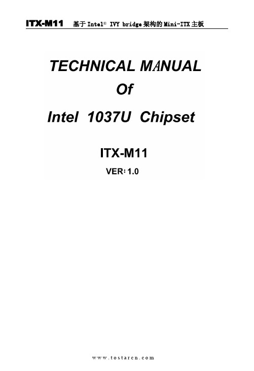
JP16
JP16 设置 设置
1-2短路 3-4短路 5-6短路 7-8短路 9-10短路 11-12短路
功 能(JP16)
RS232
+5V
COM1
+12V
RS232
+5V +12V
COM2
ห้องสมุดไป่ตู้
ITX-M11 基于 Intel® IVY bridge 架构的 Mini-ITX 主板
3 1
JBAT
设置
功能
1-2短路
正常工作状态
2-3短路 清除CMOS内容,所有BIOS设置恢复成出厂值
2、硬件来电自启功能设置(JPW1) 该板支持硬件来电自启功能,默认为关闭状态。具体设置方式如下:
3 1
JPW1
设置 1-2短路 2-3短路
功能 关闭来电自启功能 打开来电自启功能
6、SATA2与SATA3功能设置 SATA2接口与SATA3(2.5寸笔记本硬盘位)只能支持二选一,具体设置方
式如下:
R243
R185
R148
R158
3
1
将R243、R185、R148、R158 4个电阻焊接到1-2为支持SATA3(2.5寸笔记 本硬盘位)
将R243、R185、R148、R158 4个电阻焊接到2-3为支持SATA2接口
器,具有超强的图形处理能力及应用计算能力,是一款低功耗、高性能、 结 构 紧 凑 的 高 清 播 放 主 板 , 采 用 Intel® HM65 高 速 芯 片 组 , 支 持 DDR Ⅲ 1333/1066MHz内存,最大可支持8GB,内部集成Intel® HD Graphics核心显 卡,提供高性能的显示输出,支持VGA\LVDS\双HDMI显示输出,同时使用可 实现独立双显示,集成1个RTL千兆网卡,2个MPCIE插槽支持WIFI\SSD\3G模 块,1个2.5寸笔记本硬盘位,2个SATA硬盘接口。
ITX 系列主板使用说明

2.2.6 JP7 跳线说明 (1)针对 COM1 跳线
COM1 com 接(预设)
PIN9 5V 带电 PIN9 12V 带电
JP7 跳至 5-6 脚 跳至 1-2 脚 跳至 3-4 脚
11
2.2.7 JC26 插针 主机板提供了 1 组 JC26 插针,控制 COM2/COM3/COM4/COM5/
b.PWRLED 电源指示灯 d.PWRSW ATX 电源开关
主机板提供了 1 组 F_PANEL 插针,其信号定义图如下所示:
v SPEAKER 喇叭连接头 电脑的喇叭连接头(也称蜂鸣器)共有四个脚位,只要把机箱上的喇叭接头 接至此四脚位上即可使用。
v PWRLER 电源指示灯 电源指示灯为三个脚位的连接头,用来指示电脑的工作状态,当电脑一旦 上电时,指示灯常亮,反之,则不亮(注:有正负之分)。
当将风扇连接到风扇连接头上时,使用者必须将红色的线连接到 +12V 的电源针上,黑色的线连接到地线上。如果您想在 BIOS 或硬件监控 程序中观察风扇的工作状态,您必须使用支持能侦测转速功能的风扇。对 于具有速度感应器的风扇,风扇每一次转动都会产生 2 个脉冲波,系统硬 件监控将作统计逼供内产生一个风扇转动速度的报告,可在 CMOS 中显示 出风扇的转速。
结构及 尺寸
工作温度 工作湿度 应用范围
IP 3 0 X 3 产 品 规 格
Intel ATOM 230 双 核 处 理 器
FSB 533MHz INTEL 945GC +ICH7 1 x DDR2 6 6 7/53 3 M H z D IM M , 最 大 容 量 支 持 2GB 集 成 GMA950 图 形 加 速 器 板 载 Realtek ALC662 HD 音 效 芯 片 板 载 Realtek 8111D 双 网 卡 , 支 持 无 盘 2 x SATA 3 Gb/s 磁 盘 接 口 1 x PCI 插 槽 支 持 8 个 USB 2.0 端 口 (4 个 需 要 扩 展 ) 1 x 24-pin ATX 主 电 源 接 口 2 x SATA SATA 磁 盘 接 口 1 x CPU fan header CPU 风 扇 接 口 1 x SYS fan header 系 统 风 扇 接 口 1 x front panel header 前 置 面 板 插 针 1 x Audio header 前 置 音 频 跳 线 插 针 2 x USB 2.0 headers USB 扩 展 插 针 1 x Clear CMOS Header 清 CMOS 插 针 1 x VGA-H 插 针 , 1 x Mini IDE 接 口 5 x COM 扩 展 插 针 , 1 组 COM 状 态 控 制 插 针 1 x IR 红 外 线 扩 展 插 针 1 x PS/2 鼠 标 端 口 , 1 x PS/2 键 盘 端 口 1 x VGA 端 口 , 1 x COM 端 口 1 x LPT 端 口 4 x USB 2.0 端 口 2 x RJ-45 网 卡 端 口 2 x audio 接 口 (6 声 道 音 频 接 口 )
主板分类标准有哪些

主板分类标准有哪些主板是计算机的核心部件之一,它承载着CPU、内存、显卡等重要组件,是整个计算机系统的基础。
根据不同的标准,主板可以分为多种分类,下面将介绍主板的分类标准。
一、按照尺寸大小分类。
1. ATX主板。
ATX主板是一种标准的主板尺寸规格,其尺寸为305mm×244mm。
ATX主板通常具有较多的扩展插槽,适合用于高性能计算机系统。
ATX主板通常具有7个插槽,包括4个PCI插槽和3个ISA插槽。
2. Micro-ATX主板。
Micro-ATX主板是一种小尺寸的主板,其尺寸为244mm×244mm。
Micro-ATX 主板通常具有较少的扩展插槽,适合用于小型计算机系统。
Micro-ATX主板通常具有4个插槽,包括3个PCI插槽和1个ISA插槽。
3. Mini-ITX主板。
Mini-ITX主板是一种超小尺寸的主板,其尺寸为170mm×170mm。
Mini-ITX 主板通常具有非常少的扩展插槽,适合用于迷你型计算机系统。
Mini-ITX主板通常具有2个插槽,包括1个PCI插槽和1个ISA插槽。
二、按照CPU插槽类型分类。
1. LGA主板。
LGA主板是一种采用Land Grid Array插座的主板,适用于Intel处理器。
LGA 主板的CPU插槽上有许多小金属触点,用于与CPU接触传递信号。
2. PGA主板。
PGA主板是一种采用Pin Grid Array插座的主板,适用于AMD处理器。
PGA 主板的CPU插槽上有许多小金属针脚,用于与CPU接触传递信号。
三、按照内存插槽类型分类。
1. DDR主板。
DDR主板是一种支持DDR内存的主板,DDR内存具有双倍数据传输率,能够提高计算机系统的运行速度。
2. DDR2主板。
DDR2主板是一种支持DDR2内存的主板,DDR2内存相比DDR内存具有更高的频率和带宽,能够进一步提高计算机系统的运行速度。
3. DDR3主板。
DDR3主板是一种支持DDR3内存的主板,DDR3内存相比DDR2内存具有更高的频率和带宽,能够进一步提高计算机系统的运行速度。
技嘉ITX主板配置指南
技嘉ITX主板配置指南随着处理器和显卡的性能更高、功耗更低,选择小型主板在小机箱狭小的空间内,组建出性能不凡同时低功耗、散热良好的游戏平台已不是什么难事。
这些高性能小体积的迷你主机越来越受到人们的喜爱,今天学习拉小编就为大家带来一套高性能迷你主机的配置指南。
首先,我们先来一同了解一下这套配置的具体信息:处理器首选酷睿i5系列,主流酷睿i5既能保证性能价格也比较实惠,其中酷睿i5-4590默认频率3.3GHz最大睿频3.7GHz都比较较高,是其中的性能偏上的处理器,售价方面卖场1204的价格更实惠。
显卡的考虑因素较多,首先就是显卡的长度,这一点对小型主机至关重要,其次才是价格、性能,考虑到处理器选择的是酷睿i5-4590,搭配的显卡完全可以选择GTX 760及以上型号。
其中能用于小机箱的显卡并不多,综合价格因素,盈通GTX 760 4GD5 PA游戏高手是最合适的选择。
主板方面自然选择主流实用的B85 ITX型主板,虽然是小板但技嘉B85N 凤凰版-WIFI规格丝毫不差,还有独家的烈焰背光系统,搭配小机箱更是炫酷。
内存及硬盘部分,选择2个4G内存条,硬盘则是西部数据1T 7200转64MB SATA3蓝盘,预算多的用户可以选择加一个固态硬盘和比较好的机箱。
电源部分,由于GTX 760系列显卡功耗较高,建议采用500W电源,并且要特别注意电源限长。
整套配置总价4817元,采用了Intel 酷睿i5-4590和GTX 760这样的中端配置,平台性能相当不错,性价比也比较高,感兴趣的用户不妨参考一下。
产品:酷睿i5 4590 Intel CPUIntel酷睿i5-4590有3.3GHz的默认主频和3.7GHz的最大睿频,四核四线程的多任务处理效率更高。
对于游戏玩家而言,高主频的四核四线程酷睿i5-4590正是性价比最优的选择。
目前该处理器的市场报价为1204元,如果大家准备配置新的主流性能级主机,那么不妨多多关注一下。
ITX 系列主板 说明书

ITX系列用户手册你现选用的产品型号为:Rev:1.01Date:2009.02安全指导商标声明所有的品牌,产品,徽标,商标和公司名称都是属于商标或注册商标各自的拥有者。
AMI®是AMI 公司的注册商标。
Intel ® ,Celeron ® ,Pentium ®是 Intel 公司的注册商标。
Netware ®是Novell Inc.的注册商标。
PS/2 和 OS/2 是International Business Machines 公司的注册商标。
Windows ®98/ 2000/NT/XP 和Microsoft ®是Microsoft 公司的注册商标。
01. 务必请仔细通读本安全指导.02. 务必请妥善保管本手册,以备将来参考.03. 请保持本设备的干燥.04. 机箱的开口缝隙是用于通风避免机箱内的部件过热,请勿将此类开口掩盖或堵塞.05. 在将本设备与电源连接前,请确认电源电压值,将电压调整为110V/220V.06. 请将电源置于不会被践踏到的地方,并且不要在电源线上堆置任何实物.07. 插拔任何扩展卡或设备模块前,请将电源线拔下.08. 请留意手册上提到的所有注意和警告事项.09. 通电之前请确认主机箱中不要遗留螺丝等金属物件,以免电气短路烧毁其他部件.10.不得将任何液体倒入机箱开口的缝隙中,否则会产生严重损坏或电路瘫痪.11.如果发生以下情况,请找专业人员处理:v 电源线或插头损坏v 液体渗入机器内v 机器暴露在潮湿的环境中v 机器工作不正常或用户不能通过本手册的指导使其正常工作v 机器跌落或受创v 机器有明显的破损迹象目录安全指导......................................................................2商标声明......................................................................2第一章 主板简介及规格说明 (4)1.1 包装盒内物品清单.........................................................................................41.2 主板LAYOUT 图及规格表. (5)第二章 硬件设备的安装说明 (8)2.1 中央处理器的安装........................................................................................82.2 CPU 风扇的安装...........................................................................................92.3 内存的安装...................................................................................................112.4 主板跳线的设定说明.....................................................................................112.5 主机板接头说明 (12)第三章 BIOS 简介 (17)3.1 B IOS 升级更新..............................................................................................173.2 B IOS 设定.....................................................................................................173.3 B IOS 语言切换. (18)第四章 驱动程序的安装 (19)4. 1 芯片组驱动程序的安装...............................................................................194. 2 板载显卡驱动的安装...................................................................................194. 3 板载网卡驱动的安装...................................................................................194. 4 板载声卡驱动的安装...................................................................................194. 5 USB2. 0驱动程序的安装. (19)ITX-M4S1LAITX-M4S1LA-2主板规格如下表:步骤三 卸下CPU 保护盖,确认主机板上特别设计的 Socket 底座的2个凸出位置及CPU 的2个定位凹口位置方向对准后,将CPU 轻轻平放置入Socket 中,如果两者方向未对准CPU 将无法置入Socket 中。
GEMTECH ITX-8978 主板 说明书
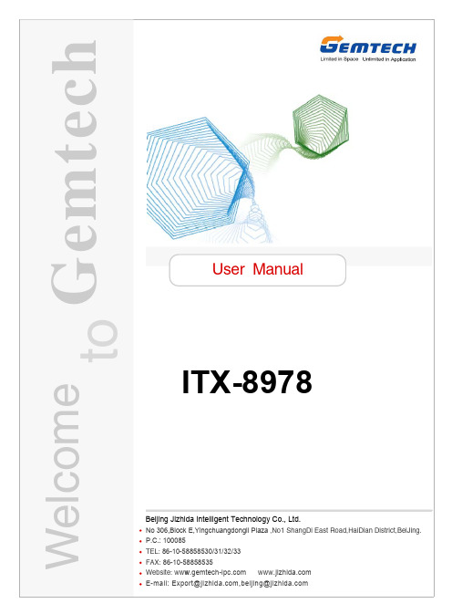
主板后面板提供以下接口:
6
VGA接口
主板提供一个DB 15-pin母头接口以连接到一个VGA监视器。
DVI接口
主板提供一个DVI-D接口以连接到一个DVI监视器。
HDMI接口
主板提供一个HDMI 1.3接口以连接到一个HDMI监视器。
SPDIF接口
主板提供两个 S/PDIF 接口,一个是同轴输出(Coaxial Out),一个是光线输出(Optical Out)。
主板使用12V 5A 的适配器电源供应器给主板供电。在连接电源供应器之前,请务必确认所有的 组件都已正确安装,并且不会造成损坏。
另外,也可用ATX 12V电源接口PW1 为主板供电。在与ATX 电源供应器相连时,请务
必确认,电源供应器的接头安装方向正确,针脚对应顺序也准确无误。将电源接头插入,并使其 与主板电源接口稳固连接。 以上两种供电方式选择一种即可。
使用手册
版本 1.1 发行日期 2009年九月
安全指导
1. 务必请仔细通读本安全指导。 2. 务必请妥善保管本手册,以备将来参考。 3. 请保持本设备的干燥。 4. 在使用前,宜将本设备置于稳固的平面上。 5. 机箱的开口缝槽是用于通风,避免机箱内的部件过热。请勿将此类开口掩盖 或堵塞。 6. 在将本设备与电源连接前,请确认电源电压值,将电压调整为110/220V。 7. 请将电源线置于不会被践踏到的地方,并且不要在电源线上堆置任何物件。 8. 插拔任何扩展卡或模块前,请都将电源线拔下。 9. 请留意手册上提到的所有注意和警告事项。 10. 不得将任何液体倒入机箱开口的缝槽中,否则会产生严重损坏或电路瘫痪。 11. 如果发生以下情况,请找专业人员处理:
Expansion Slot
华擎 B365M-ITX ac 主板说明书

120B365M-ITX/ac 1.2 规格平台•Mini-ITX 规格尺寸•稳固的电容器设计CPU•支持第8代和第9代 Intel® Core TM处理器(插座1151)•支持最高 95W 的 CPU•Digi Power design•5电源相设计•支持 Intel® Turbo Boost 2.0 技术芯片集•Intel® B365内存•双通道 DDR4 内存技术•2 x DDR4 DIMM槽•支持 DDR4 2666/2400/2133 非 ECC,非缓冲内存•支持 ECC UDIMM 内存模块(非 ECC 模式操作)•支持系统内存最大容量:32GB•支持 Intel® Extreme Memory Pro le (XMP) 2.0•DIMM插槽中15μ金触点扩充槽• 1 x PCI Express 3.0 x16插槽(PCIE1:x16 模式)* 支持 NVMe SSD 用作启动盘•1 x 垂直 M.2 Socket (Key E),捆绑有 WiFi-802.11ac 模块(在后 I/O 上)图形* 只有 GPU 集成的处理器才支持 Intel® UHD Graphics 内置视效和 VGA 输出。
•支持 Intel® UHD Graphics 内置视效: Intel® 快速同步视频,采用 AVC、MVC (S3D) 和 MPEG-2 Full HW Encode1、Intel® InTru TM 3D、Intel® Clear Video HD 技术、Intel®Insider TM、Intel® UHD Graphics•DirectX 12•HW A 编码/解码: AVC/H.264、HEVC/H.265 8-bit、HEVC/H.265 10-bit、VP8、VP9 8-bit、VP9 10-bit (仅解码)、MPEG2、MJPEG、VC-1 (仅解码)121•3个图形输出选项: DVI-I、HDMI和DisplayPort 1.2•支持三台显示器•支持HDMI 1.4,30Hz时最大分辨率可达4K x 2K(4096x2160)•支持 DisplayPort 1.2,60Hz 时最大分辨率达 4K x 2K(4096x2304)•支持 DVI-I,60Hz 时最大分辨率达 1920x1200•通过HDMI 1.4端口(需要兼容的HDMI显示器)支持Auto Lip Sync、Deep Color (12bpc), xvYCC和HBR(高位速率音频)•通过DVI-I、HDMI 1.4和DisplayPort 1.2端口支持HDCP 2.2•通过 HDMI 1.4和 DisplayPort 1.2 端口支持支持 4K 超高清(UHD)播放音频•7.1 CH 高清音频 (Realtek ALC887 音频编解码器)*要配置 7.1 CH 高清音频,需要使用高清前面板模块和通过音频驱动程序启用多通道音频功能。
电脑主板选择指南ATXMicroATX还是MiniITX

电脑主板选择指南ATXMicroATX还是MiniITX电脑主板选择指南:ATX、MicroATX还是MiniITX电脑主板对于电脑性能和功能的决定性影响不可小觑。
不同的主板规格,例如ATX、MicroATX和MiniITX,可以满足不同用户对于电脑的需求。
本文将为您介绍这三种主板规格的特点和适用场景,帮助您在购买时做出明智的选择。
一、ATX主板ATX(Advanced Technology eXtended)是主板领域最常见的规格之一。
ATX主板的尺寸通常为305mm x 244mm,具有众多的扩展插槽和接口,适用于高配置、高性能电脑的搭建。
ATX主板的较大尺寸使得其更适合于较大的机箱,拥有更多的扩展插槽,如PCI-E插槽和RAM插槽,以支持更多的显卡和内存。
这使得ATX主板非常适合用于游戏电脑或专业工作站,这些领域对于计算性能和扩展性要求较高。
二、MicroATX主板MicroATX主板是ATX主板的一种缩小版,尺寸通常为244mm x 244mm。
相比于ATX主板,MicroATX主板在扩展性方面略有减少,但在尺寸、成本和适用场景上更具优势。
MicroATX主板相对较小的尺寸使得它更适合于小型机箱和轻薄电脑的搭建。
虽然MicroATX主板的扩展插槽和内存插槽较少,但对于一般用户而言,其仍然能够满足日常使用所需的性能和功能。
尤其是在家庭娱乐电脑和办公电脑等场景中,MicroATX主板更加受欢迎。
三、MiniITX主板MiniITX主板是最小尺寸的主板规格,尺寸通常为170mm x 170mm。
MiniITX主板的小巧尺寸使得它非常适合于小型和便携电脑的搭建,例如一体机和HTPC。
尽管MiniITX主板的扩展插槽和内存插槽非常有限,但由于其紧凑的尺寸和低功耗特性,它成为了家庭影音娱乐和办公环境中的理想选择。
不仅如此,MiniITX主板还可以用于嵌入式系统和迷你电脑的开发,实现更多创意和特殊用途。
拓朗ITX-TL68-PCIE VER 1.1 Sandy Ivy Bridge-U ITX 主板用

ITX-TL68-PCIE VER 1.1Sandy/Ivy Bridge-U ITX主板ITX-TL68-PCIE VER1.1 用户手册User Guide一、产品简介ITX-TL68-PCIE为ITX系列工业主板,支持Sandy Bridge-U或Ivy Bridge-U整个系列CPU。
可广泛应用于商显、机器视觉、医疗仪器、工业控制、金融设备、云终端等领域。
ITX-TL68-PCIE主板主要特点如下:1.支持Sandy Bridge-U或Ivy Bridge-U Celeoron,Pentium,Core®I3/I5/I7 CPU;2.支持单通道1600/1333MHz DDR3 SO-DIMM内存,最大支持8GB;3.显示支持VGA、HDMI、LVDS接口;4.可支持2个千兆网络;5.可支持1个Mini-PCIe(WIFI)和1个M.2接口支持5G模块;6.可支持8个USB接口;7.内置6个RS232串口,其中COM1可支持RS485/422,COM2可支持RS485;8.支持PCIE扩展槽;9.支持Win XP、WIN7、WIN10、Linux系统;二、主板框架图LVDSVGA DB15 PORT PCIE2.0USB USB2.0 6PORTS FDIDMIUSB3.0 2PORTS RTL8111H 2*SATA2.0 PORT SATANM70For WIFI/4GPCIE/USBMini-PCIe PORT GIGABYTE PHY1Super I/O 2*COM IT87282*FANLPC I/FGPIO SPI FLASHSPIMSATA3.0 SSD HDMI PORT12CH 24Bit LVDS DDPC LPT/PS2GIGABYTE PHY2RTL8111H IVY BridgeNote:COM1 can support RS232485/422Super I/O 4*COMIT8760PCIE X16 SLOTCOM2 can support RS232/485IntelSODIMMDDR3 CHB1600MHz DDR3L PCIE2.0PCIE2.0PCIE2.0CRT LINE_OUT/MIC/AMPAUDIO ALC662AZALIAM.2 Key B PORT For WIFI/5G三、主板详细规格项目描述处理器Intel®Core i3-3217UIntel®Core i5-3317U 双核1.8GHz双核1.7GHz (Up to 2.6GHz)可兼容Intel Celeoron,Pentium,Core®I3/I5/I7 Sandy /Ivy Bridge-U 系列处理器芯片组 采用Intel® HM76/HM77等高速芯片组 内 存1*SO-DIMM 内存插槽支持单通道1600/1333MHz DDR3/1.5V 内存,最大支持8GB 显 示集成Intel 核芯显卡 40001* VGA ,1*HDMI 接口,1*LVDS 接口 支持VGA 、HDMI 、LVDS 同步/异步双显网络2* Realtek RTL8111H千兆网卡,支持网络唤醒/PXE存储1* 2.5寸硬盘接口1* mSATA3.0插槽(长卡)音频板载ALC662/262/ALC888等6声道高保真音频控制器支持MIC/Line-out,支持2欧5W双声道扩展插槽1* Mini-PCIe插槽,支持WIFI 1*m.2插槽(支持4G 5G模块) 1* PCIE X16插槽背板I/O接口1* HDMI侧插显示接口1*VGA接口2* USB2.0接口+2*USB3.0接口2* RJ-45 千兆网络接口1* Line out接口(绿色)1* PS2键盘鼠标接口1* 9~36V DC电源输入接口(2PIN 5.08mm间距凤凰端子)内置I/O接口1* LVDS接口2*15pin,支持双通道24bit1* 屏背光供电接口1*6pin4* USB2.0接口2*5Pin1* 前置音频接口2*5pin1* 功放接口1*4pin6* COM接口(其中COM1可支持RS485/422,COM2可支持RS485,COM3/4第9P带电)1* LPT接口1* SIM接口排针1* 硬盘供电接口1* 4pin ATX电源接口1* 前面板开关按钮和指示灯接口2*5Pin风扇接口1*4pin CPU风扇接口,1*4pin系统风扇接口GPIO 支持4路输入输出GPIOBIOS 32Mb Flash ROM看门狗支持硬件复位功能(256级,0~255秒)操作系统Windows XP/Windows 7/Windows 10/Linux 电源类型采用DC 9~36V电源供电工作温度60℃~-10℃储存温度-20℃~70℃工作湿度5%-95%相对湿度,无冷凝四、主板安装安全注意:•安装前请勿任意撕毁主板上的序列号及代理商保修贴纸等,否则会影响到产品保修期限的认定标准。
一寸小一寸巧Mini-ITX主板选购谈

26文/KKK一寸小 一寸巧Mini-ITX主板选购谈我想大家从题图上就能看出Mini-ITX主板在尺寸上的优势了吧。
而且,Mini-ITX主板问世也有足够长的年头了,之所以在最近才开始走红,也跟广大消费者的需求变化有关。
以往我们追求的是性能强大、功能全面,而现在大家在乎的是产品在具体应用环境下的表现。
在HTPC平台上,Mini-ITX主板无疑具有得天独厚的优势。
小尺寸成为了优势大多数Mini- ITX主板都采用17cm×17cm尺寸设计。
虽然狭窄的板身让它无法提供较大的扩展空间,但在功能高度整合化的今天,声、显、网卡已经完美融合到了主板上,更多第三方功能芯片的加入也为Mini- ITX主板提供了诸如蓝牙、WiFi、USB 3.0、Mini PCI-E接口等额外功能,让小巧的Mini- ITX主板在功能方面得到了最大化的完善。
而尽管空间有限,主板厂商们还是会竭尽全力为用户们提供更大的扩展空间,独立显卡接口等亦不在话下。
在功能和扩展性得到进一步完善的情况下,小尺寸反而成为了优势,让Mini- ITX主板能够更加自如地适应HTPC等对空间有严格要求的平台的需求。
热门Mini-ITX主板产品推荐整合显卡已然够用Mini- ITX主板兴起的另一个原因在于目前的整合显卡性能已经变得足够强大,无论是Intel的HD系列核心显卡还是AMD的Radeon HD融合独显核心,都有足够的性能来满足主流用户的需求。
与此同时,它们在高清视频编解码方面也拥有不错的实力,无论是Intel的Quick Sync Video还是AMD 的UVD 3.0引擎,都能够在最小的资源占用率下流畅地驾驭高清视频。
给用户提供惬意的使用体验。
Mini-ITX也需要取舍在选购Mini- ITX时,我们也是需要做很多取舍的。
总体而言,越是希望Mini- ITX主板的功能接近于标准的ATX主板,那价格就越贵。
所以我们尽量选择满足自己应用需求的产品即可。
ATXM-ATXITX各种主板尺寸

ATXM-ATXITX各种主板尺寸ATX M-ATX ITX 各种主板尺寸AMD Ryzen 已经发布一段时间了,不少观望的朋友也准备装机了,说到装机不得不说主板,主板尺寸大小各有不同,例如 ATX 、M-ATX 、ITX 、STX 这些标准究竟什么意思,快跟着店铺一起学习吧。
主板尺寸差别大乱七八糟,粗略数了一下有十几种之多,目前常见的主要还是 ATX 、Micro-ATX(简称M-ATX)、mini-ITX(简称ITX)、mini-STX(简称STX)几种,有些人以为尺寸越大越值钱,事实真是这样吗?常用标准主板尺寸大小图表ATX 可以理解为全尺寸主板(其实要说全尺寸主板还有一个WTX 更大,给服务器用的,尺寸是356mm×425mm),各接口配备齐全显著特征是内存多位4条插槽,下方的插槽一般是7个扩展插槽,但是要占用8个扩展插槽位(现在一般也就是4条PCI-E全长插槽+2个PCI-E 1×插槽,或者是m.2插槽)。
另外,有些ATX主板为了进一步扩充性能,可能会在宽度上进行调整(比如高端X99主板),但是长度一定会遵循规范否则无法安装到机箱上,一般高端游戏类主板都是ATX版型。
M-ATX 就是缩小版的 ATX,内存一般也是4条插槽,扩展PCI-E 插槽一般只有4个槽位占用5个空间。
另外,M-ATX是常见规格里尺寸版本最多的一种,各种拉长、拍扁各种方式都有,它们的宽度也不会改变都是 244mm 。
ITX 是专门为小型电脑设计的主板规格,尺寸170mm×170mm ,包括一条全尺寸PCI-E 插槽,可以安装独立显卡,因为主板尺寸变小机箱也随之变小,很多玩家非常喜欢。
另外要提的就是 Thin-ITX 其实它的尺寸跟 ITX 一样,不过区别在I/O 接口部分,硬性规定了高度限制,不允许超过 25mm 这是为了塞进更小的'机箱,另外 Thin-ITX 基本都是采用笔记本内存、取消PCI-E插槽的主板产品,毫无扩展性可言。
华擎 B75M-ITX 使用手册
簡體中文
This Manual: /file/2617774
警告 請了解超頻具有不可避免的風險 , 這些超頻包括調節 BIOS 設置、運用異步超 頻技術或使用第三方超頻工具。超頻可能會影響您的系統穩定性 , 甚至會導 致系統組件和設備的損壞。這種風險和代價須由您自己承擔 , 我們對超頻可 能導致的損壞不承擔責任。
平台,可最大程度提高員工效率、電腦性能与數据安全性。包含的應用程 序有 Software Monitor、PC Health Center、Data Backup & Restore、 Energy Saver 与 USB Blocker。 4、 這款主板支援雙通道內存技術。在您實現雙通道內存技術之前,為能正確 安裝,請確認您已經閱讀了第 17 頁的內存模組安裝指南。 5、 由于操作系統的限制,在 Windows® 7 / VistaTM / XP 下,供系統使用的實 際內存容量可能小于 4GB。對於 Windows® 操作系統搭配 64 位元 CPU 來說 , 不會存在這樣的限制。您可以通過華擎 XFast RAM 來利用 Windows® 無法使 用的內存。 6、 若要使 PCI Express 運行于 Gen 3 速度,您必須安裝 Ivy Bridge CPU。若 您安裝了 Sandy Bridge CPU,則 PCI Express 只能運行于 Gen 2 速度。 7、 最大共享內存大小由芯片組廠商定義並且可以更改。請查閱 I n t e l ® 網站 了解最新資訊。 8、 您只能從三種顯示器中選擇兩種使用。D-Sub、DVI-D 與 HDMI 顯示器不 能同時使用。此外 , 使用 DVI 轉 HDMI 轉接器 , 可使 DVI-D 端口具備與 HDMI 端口一樣的功能。 9、 只有 Windows® 7 64 位元 /7 可支持 xvYCC 與 Deep Color。只有當顯示器 在 EDID 中支持 12bpc 時 ,Deep Color 模式才會被開啟。只有 Windows® 7 64 位元 /7/VistaTM 64 位元 /VistaTM 支持 HBR。 10、 在麥克風輸入方面,這款主板支持立體聲和單聲道這兩種模式。在音頻輸 出方面,這款主板支持 2 聲道、4 聲道、6 聲道以及 8 聲道模式。請查閱 第 3 頁的表格瞭解正確的連接方式。 11、ASRock Extreme Tuning Utility (AXTU) 是一個多合一的工具,可在用戶 友好的界面中微調不同的系統功能,包括硬件監控、風扇控制、超頻、O C DNA 和 IES。在 Hardware Monitor(硬件監控)中,顯示系統的主要參數。 在 Fan Control(風扇控制)中,顯示風扇速度和溫度,以便您進行調整。 在 Overclocking(超頻)中,您可以對 CPU 進行超頻,以优化系統性能。 在 OC DNA 中,您可以將自己的 OC 設置保存為配置文件,并与您的朋友共 享。您的朋友可以將您的 O C 配置文件加載他們的系統中,從而得到相同 的 OC 設置。在 IES(智能節能)中,電壓調節器可以在 CPU 核心空閒時減 少輸出相位數,以提高效率且不影響運計算性能。關于 ASRock Extreme Tuning Utility (AXTU) 的操作步驟,請訪問我們的网站。 華擎網站:
itx主板结构标准

itx主板结构标准
ITX主板是一种微型主板,其结构标准主要包括以下几个方面:
1.尺寸:ITX主板的尺寸通常为170mm x 170mm,这是其最显著的特点之一,使得它
非常适合用于小型机箱和便携式设备。
2.CPU插槽:ITX主板通常配备LGA或Socket类型的CPU插槽,用于安装处理器。
具体的插槽类型取决于主板所支持的处理器系列。
3.内存插槽:ITX主板通常提供至少两个内存插槽,用于安装DDR类型的内存条。
这
些插槽通常支持双通道内存技术,以提高内存带宽和性能。
4.扩展插槽:尽管ITX主板尺寸较小,但它们仍然提供了一定数量的扩展插槽,如PCI
Express插槽和M.2插槽等。
这些插槽可以用于安装各种扩展卡,如显卡、声卡、网卡等。
5.接口:ITX主板还提供了丰富的接口选项,包括SATA接口、USB接口、HDMI接
口、DisplayPort接口等。
这些接口可以满足各种设备的连接需求。
6.电源连接:ITX主板通常采用24针ATX电源接口或更小的电源接口,以连接电源
供应器并提供稳定的电力供应。
需要注意的是,由于ITX主板尺寸较小,因此在设计和制造时需要更高的精度和集成度。
同时,由于其扩展性相对有限,所以在选择ITX主板时需要仔细考虑自己的需求和预算。
此外,ITX也分为多种规格,比如mini-ITX等。
其中,mini-ITX主板的规格较小,尺寸为170mm x 170mm,但仍然保留了基本的扩展插槽和接口选项。
这种主板非常适合用于小型机箱和便携式设备,可以满足基本的计算需求。
以上信息仅供参考,如有需要,建议咨询专业的电脑硬件人员。
ITX-M50 VER 2.2(2015.10.15)主板说明书

Intel○R Bay Trail Processor ITX-M50 VER:2.2说明除列明随产品配置的配件外,本手册包含的内容并不代表本公司的承诺,本公司保留对此手册更改的权利,且不另行通知。
对于任何因安装、使用不当而导致的直接、间接、有意或无意的损坏及隐患概不负责。
订购产品前,请向经销商详细了解产品性能是否符合您的需求。
本手册所涉及到的其他商标,其所有权为相应的产品厂家所拥有。
本手册内容受版权保护,版权所有。
未经许可,不得以机械的、电子的或其它任何方式进行复制。
订购信息温馨提示1、产品使用前,务必请仔细阅读产品说明书。
2、对未准备安装的主板,应将其保存在防静电保护袋中。
3、在从包装袋中拿主板前,应将手先置于接地金属物体上一会儿,以释放身体及手中的静电4、在使用前,宜将主板置于稳固的平面上。
5、请保持主板的干燥,散热片的开口缝槽是用于通风,避免机箱内的部件过热。
请勿将此类开口掩盖或堵塞。
6、在将主板与电源连接前,请确认电源电压值。
7、请将电源线置于不会被践踏的地方,且不要在电源线上堆置任何物件。
8、当您需连接或拔除任何设备前,须确定所有的电源线事先已被拔掉。
9、为避免人体被电击或产品被损坏,在每次对整机、板卡进行拔插或重新配置时,须先关闭交流电源或将交流电源线从电源插座中拔掉。
10、请留意手册上提到的所有注意和警告事项。
11、为避免频繁开关机对产品造成不必要的损伤,关机后,应至少等待30秒后再开机。
12、设备在使用过程中出现异常情况,请找专业人员处理。
13、请不要将本设备置于或保存在环境温度高于70℃上,否则会对设备造成伤害。
注意:如果电池换置不当,会产生爆炸的危险。
请务必使用同一型号的或者相当类型的且为制造商推荐的电池。
目录第一章产品介绍................................................................................................... - 4 -1.1 产品规格 .................................................................................................. - 5 - 第二章安装说明................................................................................................. - 10 -2.1 主板尺寸图............................................................................................. - 10 -2.2 接口位置示意图...................................................................................... - 11 -2.3 安装步骤 ................................................................................................ - 12 -2.4 内存安装 ................................................................................................ - 12 -2.5 跳线功能设置 ......................................................................................... - 12 -2.5.1 CMOS内容清除/保持设置(JBAT1).................................................. - 12 -2.5.2 JPW1选择跳线..................................................................................... -12 -2.5.3 SATA2、SATA5接口功能设置(SATA1_SW1) .................................. -12 -2.6 接口说明 ................................................................................................ - 14 -2.6.1 SATA接口(SATA2、PWROUT1) .............................. 错误!未定义书签。
MS-9832 微星miniITX工控主板说明书 用户手册
G52-98321X1Copyright NoticeThe material in this document is the intellectual property of M ICRO-STAR INTERNATIONAL. We take every care in the preparation of this document, but no guarantee is given as to the correctness of its contents. Our products are under continual improvement and we reserve the right to make changes without notice.TrademarksAll trademarks are the properties of their respective owners.Intel® and Pentium® are registered trademarks of Intel Corporation.AMD, Athlon™, Athlon™ XP, Thoroughbred™, and Duron™ are registered trade-marks of AMD Corporation.NVIDIA, the NVIDIA logo, DualNet, and nForce are registered trademarks or trade-marks of NVIDIA Corporation in the United States and/or other countries.PS/2 and OS®/2 are registered trademarks of International Business Machines Corporation.Windows® 98/2000/NT/XP/Vista are registered trademarks of Microsoft Corporation. Netware® is a registered trademark of Novell, Inc.Award® is a registered trademark of Phoenix Technologies Ltd.AMI® is a registered trademark of American Megatrends Inc.Revision HistoryRevision Revision History DateV1.0First release September 2008Technical SupportIf a problem arises with your system and no solution can be obtained from the user’s manual, please contact your place of purchase or local distributor. Alternatively, please try the following help resources for further guidance.Contact our technical staff at .Safety Instructions1.Always read the safety instructions carefully.2.Keep this User’s Manual for future reference.3.Keep this equipment away from humidity.y this equipment on a reliable flat surface before setting it up.5.The openings on the enclosure are for air convection hence protects the equip-ment from overheating. DO NOT COVER THE OPENINGS.6.Make sure the voltage of the power source and adjust properly 110/220V be-fore connecting the equipment to the power inlet.7.Place the power cord such a way that people can not step on it. Do not placeanything over the power cord.8.Always Unplug the Power Cord before inserting any add-on card or module.9.All cautions and warnings on the equipment should be noted.10.Never pour any liquid into the opening that could damage or cause electricalshock.11.If any of the following situations arises, get the equipment checked by servicepersonnel:The power cord or plug is damaged.Liquid has penetrated into the equipment.The equipment has been exposed to moisture.The equipment does not work well or you can not get it work according toUser’s Manual.The equipment has dropped and damaged.The equipment has obvious sign of breakage.12. DO NOT LEAVE THIS EQUIPMENT IN AN ENVIRONMENT UNCONDITIONED, STOR-AGE TEMPERATURE ABOVE 600 C (1400F), IT MAY DAMAGE THE EQUIPMENT.CAUTION: Danger of explosion if battery is incorrectly replaced.Replace only with the same or equivalent type recommended by themanufacturer.FCC-B Radio Frequency Interference StatementThis equipment has beentested and found to complywith the limits for a Class Bdigital device, pursuant to Part15 of the FCC Rules. These limits are designed to provide reasonable protection against harmful interference in a residential installation. This equipment generates, uses and can radiate radio frequency energy and, if not installed and used in accor-dance with the instructions, may cause harmful interference to radio communications. However, there is no guarantee that interference will not occur in a particular installation. If this equipment does cause harmful interference to radio or television reception, which can be determined by turning the equipment off and on, the user is encouraged to try to correct the interference by one or more of the measures listed below.Reorient or relocate the receiving antenna.Increase the separation between the equipment and receiver.Connect the equipment into an outlet on a circuit different from that towhich the receiver is connected.Consult the dealer or an experienced radio/television technician for help.Notice 1The changes or modifications not expressly approved by the party responsible for compliance could void the user’s authority to operate the equipment.Notice 2Shielded interface cables and A.C. power cord, if any, must be used in order to comply with the emission limits.VOIR LA NOTICE D’INSTALLATION AVANT DE RACCORDER AU RESEAU.Micro-Star InternationalMS-9832This device complies with Part 15 of the FCC Rules. Operation is subject to the following two conditions:(1) this device may not cause harmful interference, and(2) this device must accept any interference received, including interference thatmay cause undesired operation.WEEE (Waste Electrical and Electronic Equipment) StatementCONTENTSCopyright Notice (ii)Trademarks (ii)Revision History (ii)Technical Support (ii)Safety Instructions (iii)FCC-B Radio Frequency Interference Statement (iv)WEEE (Waste Electrical and Electronic Equipment) Statement (v)Chapter 1 Product Overview................................................................................1-1 Mainboard Specifications...................................................................................1-2 Block Diagram.......................................................................................................1-4 Mainboard Layout................................................................................................1-5 Board Dimension..................................................................................................1-6 Back Panel & I/O Shield Drawing........................................................................1-7 Power Consumption............................................................................................1-8 Safety Compliance & MTBF..............................................................................1-10 Chapter 2 Hardware Setup....................................................................................2-1 Quick Components Guide....................................................................................2-2 Memory.................................................................................................................2-3 Power Supply......................................................................................................2-4 Back Panel I/O......................................................................................................2-5 Connector............................................................................................................2-7 Jumper................................................................................................................2-13 Slot......................................................................................................................2-15 Chapter 3 BIOS Setup.............................................................................................3-1 Entering Setup.....................................................................................................3-2 The Main Menu.....................................................................................................3-4 Standard CMOS Features...................................................................................3-6 Advanced BIOS Features...................................................................................3-9 Integrated Peripherals.......................................................................................3-13 Power Management Setup...............................................................................3-16 PnP/PCI Configurations......................................................................................3-19 H/W Monitor........................................................................................................3-21 Load Fail-Safe / Optimized Defaults................................................................3-22 BIOS Setting Password.....................................................................................3-23 Chapter 4 System Resources.............................................................................4-1 Watch Dog Timer Setting.....................................................................................4-2 AMI POST Code...................................................................................................4-3 Resource List......................................................................................................4-7Product OverviewProduct Overview1-31-4Product Overview Mainboard LayoutIM-945GC (MS-9832 v1.X) Mini ITX MainboardIM-945GC-D (MS-9832 v1.X) Mini ITX Mainboard1-51-61-7Product OverviewBack Panel & I/O Shield Drawing1-8Product OverviewComponent DescriptionCPU Intel® Atom™ Processor 200 SeriesMemory Corsair 1G DDR2-800 x1Add-On VGA NAHard Disk Western 80G IDE 7200rpm HDD x1Operating system Microsoft® Windows XP®Professional SP2MS-9832 (DC) 12V inputCurrent(A) WattEnter DOS (Stable) 1.613 A 19.356WEnter BIOS (Stable) 1.600 A 19.200WIdle 1.578 A 18.936WCPU Stress 100% 1.760 A 21.120WWindowsstress(3dMARK2002.213 A 26.556W6)Windows DesktopStandby S1 without1.270 A 15.240WLAN connected(stable)Windows DesktopStandby S3 without0.240 A 2.880WLAN connected(stable)Windows DesktopHibernate S40.175 A 2.100Wwithout LANconnected (stable)Windows DesktopSoft Off S5 without0.188 A 2.256WLAN connected(stable)1-91-10Calculation ModelOperationTemperature (°C)OperatingEnvironmentDuty Cycle (FITs.) MTBF (hr.) Telcordia Issue 1 25GB, GC - GroundBenign,Controlled3,480.218071 287,3389832-02S MTBF - Reliability PredictionCalculation ModelOperationTemperature (°C)OperatingEnvironmentDuty Cycle (FITs.) MTBF (hr.)Telcordia Issue 1 25 GB, GC - GroundBenign,Controlled3,657.522543 273,409HardwareSetup2-1PCI1, p.2-14 2-2MemoryDDR2240-pin, These DIMM slots are intended for system memory modules.Installing Memory Modules1.Locate the DIMM slots on the mainboard. Flip open the retaining clip at each sideof the DIMM slot.2.Align the notch on the DIMM with the key on the slot. Insert the DIMM vertically intothe DIMM slot. Then push it in until the golden finger on the DIMM is deeply inserted in the DIMM slot. The retaining clip at each side of the DIMM slot will automatically close if the DIMM is properly seated.3.Manually check if the DIMM has been locked in place by the retaining clips at thesides.PIN SIGNAL 1GND 2GND 312V 412VPin DefinitionSystem Power Connector: JPW1 (for IM-945GC-D)This 12V power connector is used to provide power to the system & CPU.SATA HDD Power Connector: JPWR2 (for IM-945GC-D)These connectors provide power to the SATA hard disk drives.JPW11342JPWR2GND GND +12V VCC5Back Panel I/OSpeed I ndicatorActivity IMouse/KeyboardThe standard PS/2® mouse/keyboard DIN connector is for a PS/2® mouse/keyboard. Serial PortThe serial port is a 16550A high speed communications port that sends/ receives 16bytes FIFOs. You can attach a serial mouse or other serial devices directly to the connector.VGA PortThe DB15-pin female connector is provided for monitor.USB PortThe USB (Universal Serial Bus) port is for attaching USB devices such as keyboard,mouse, or other USB-compatible devices. LANThe standard RJ-45 LAN jack is for con-nection to the Local Area Network (LAN).You can connect a network cable to it.Keyboard USB Ports CONN1USB Ports VGA PortMICCONN2CONN2Serial PortConnectorIDE Connector: IDE1This connector supports IDE hard disk drives, optical disk drives and other IDE devices.IDE1nect to one Serial ATA device.SATA1SATA3SATA2SATA4Fan Power Connector: CPUFAN1, SYSFAN1The fan power connectors support system cooling fan with +12V. When connecting the wire to the connectors, always note that the red wire is the positive and should be connected to the +12V; the black wire is Ground and should be connected to GND.If the mainboard has a System Hardware Monitor chipset onboard, you must use a specially designed fan with speed sensor to take advantage of the CPU fan control.Serial Port Connector: COM1, COM2, COM3This connector is a 16550A high speed communications port that sends/receives 16bytes FIFOs. You can attach a serial device to it through the optional serial port bracket.Pin DefinitionCOM219210 COM110291 COM319210SYSFAN1FAN_RPM+12VGND CPUFAN1F A N _R P M +12VG N DF A N _P W MPin DefinitionFront Panel Connector: JFP1The mainboard provides one front panel connector for electrical connection to the front panel switches and LEDs. The JFP1 is compliant with Intel ® Front Panel I/O Connectivity Design Guide.JFP1LED Reset Switch Power Power2-13Hardware SetupClear CMOS Jumper: JBAT1There is a CMOS RAM onboard that has a power supply from an external battery to keep the data of system configuration. With the CMOS RAM, the system can auto-matically boot OS every time it is turned on. If you want to clear the system configuration,set the jumper to clear data.JumperClear Data1Keep Data1JBAT112-141+5V +12V JCOMP2(for COM2)2-15Hardware SetupSlotPCI (Peripheral Component Interconnect) Express SlotThe CON1 is Mini PCI-E connector for wireless LAN, TV tuner, and Robson NAND Flash.PCI (Peripheral Component Interconnect) SlotThe PCI slot supports LAN card, SCSI card, USB card, and other add-on cards that comply with PCI specifications.32-bit PCI SlotMini PCI-E SlotThis page is intentionally left blank.viiiBIOS Setup3-13-2BIOS Setup 3-3Getting HelpAfter entering the Setup menu, the first menu you will see is the Main Menu.Main MenuThe main menu lists the setup functions you can make changes to. You can use the arrow keys ( ↑↓ ) to select the item. The on-line description of the highlighted setup function is displayed at the bottom of the screen.Sub-M enuIf you find a right pointer symbol (as shown in the right view)appears to the left of certain fields that means a sub-menu canbe launched from this field. A sub-menu contains additional op-tions for a field parameter. You can use arrow keys ( ↑↓ ) to highlight the field and press <Enter> to call up the sub-menu. Then you can use the control keys to enter values and move from field to field within a sub-menu. If you want to return to the main menu, just press the <Esc >.General Help <F1>The BIOS setup program provides a General Help screen. Y ou can call up this screen from any menu by simply pressing <F1>. The Help screen lists the appropriate keys to use and the possible selections for the highlighted item. Press <Esc> to exit the Help screen.Control Keys3-4Standard CMOS FeaturesUse this menu for basic system configurations, such as time, date etc.Use this menu to setup the items of AMI ® special enhanced features.Integrated PeripheralsUse this menu to specify your settings for integrated peripherals.Power Management SetupUse this menu to specify your settings for power management.PnP/PCI ConfigurationsUse this menu to specify PnP/PCI settings.H/W MonitorThis entry shows your PC health status.Use this menu to load the default values set by the BIOS vendor for stable system performance.BIOS SetupLoad Optimized DefaultsUse this menu to load the default values set by the mainboard manufacturer specifi-cally for optimal performance of the mainboard.BIOS Setting PasswordUse this menu to set the password for BIOS.Save changes to CMOS and exit setup.Exit Without SavingAbandon all changes and exit setup.3-53-6 Date (MM:DD:YY)This allows you to set the system to the date that you want (usually the current date).The format is <day> <month> <date> <year>.day Day of the week, from Sun to Sat, determined byBIOS. Read-only.month The month from Jan. through Dec.date The date from 1 to 31 can be keyed by numeric function keys.year The year can be adjusted by users.Time (HH:MM:SS)This allows you to set the system time that you want (usually the current time). The time format is <hour> <minute> <second>.This setting specifies the operation mode of the ATA/IDE device.Vender, SizeThese settings show the IDE/SATA device information. Read only.LBA/Large ModeThis setting allows you to enable or disable the LBA Mode. Setting to [Auto]enables LBA mode if the device supports it and has not been formatted withLBA mode disabled.This setting specifies the DMA Mode.Hard Disk S.M.A.R.T.This setting allows you to activate the S.M.A.R.T. (Self-Monitoring Analysis &Reporting Technology) capability for the hard disk drives. S.M.A.R.T is a utilitythat monitors your disk status to predict hard disk failure. This gives you anopportunity to move data from a hard disk that is going to fail to a safe placebefore the hard disk becomes off-line.Boot Sector ProtectionThe item is to set the Virus Warning feature for IDE Hard Disk boot sector protection.If the function is enabled and any attempt to write data into this area is made, BIOSwill display a warning message on screen and beep.Setting the item to [Enabled] allows the system to boot within 5 seconds since it willskip some check items.This setting is to set the Num Lock status when the system is powered on. Setting to[On] will turn on the Num Lock key when the system is powered on. Setting to [Off]will allow users to use the arrow keys on the numeric keypad.This field is used to enable or disable the APIC (Advanced Programmable Interrupt Controller). Due to compliance with PC2001 design guide, the system is able to run in APIC mode. Enabling APIC mode will expand available IRQ resources for the system. MPS Table VersionThis field allows you to select which MPS (Multi-Processor Specification) version to be used for the operating system. You need to select the MPS version supported byAdvanced BIOS FeaturesFunctionThe processor uses Hyper-Threading technology to increase transaction rates and reduces end-user response times. The technology treats the two cores inside the processor as two logical processors that can execute instructions simultaneously. In this way, the system performance is highly improved. If you disable the function, the processor will use only one core to execute the instructions. Please disable this item if your operating system doesn ’t support HT Function, or unreliability and instability may occur.Intel's Execute Disable Bit functionality can prevent certain classes of malicious "buffer overflow" attacks when combined with a supporting operating system.This functionality allows the processor to classify areas in memory by where application code can execute and where it cannot. W hen a malicious worm attempts to insert code in the buffer, the processor disables code execution,preventing damage or worm propagation.This setting sets Max CPUID extended function value to 3.Chipset FeatureThe High Precision Event Timer (HPET) was developed jointly by Intel and Microsoft to meet the timing requirements of multimedia and other time-sensitive applications.In addition to extending the capabilities and precision of a system, the HPET also improves system performance.VGA Share MemoryThe system shares memory to the onboard VGA card. This setting controls the exact memory size shared to the VGA card.DVMT Mode SelectIntel's Dynamic Video Memory Technology (DVMT) allows the system to dy-namically allocate memory resources according to the demands of the system at any point in time. The key idea in DVMT is to improve the efficiency of the memory allocated to either system or graphics processor.It is recommended that you set this BIOS feature to DVMT Mode for maximum performance. Setting it to DVMT Mode ensures that system memory is dynami-cally allocated for optimal balance between graphics and system performance.When set to DVMT/FIXED Mode, the graphics driver will allocate a fixed amount of memory as dedicated graphics memory, as well as allow more system memory to be dynamically allocated between the graphics proces-sor and the operating system.1st Boot DeviceThe items allow you to set the first boot device where BIOS attempts to load the disk operating system.Boot From Other DeviceSetting the option to [Yes] allows the system to try to boot from other device. if the system fails to boot from the 1st boot device.USB Controller This setting allows you to enable/disable the onboard USB 1.1/ 2.0 controller. Onboard LAN ControllerThis setting allows you to enable/disable the onboard LAN controller.The items enable or disable the initialization of the onboard LAN Boot ROM during bootup. Selecting [Disabled] will speed up the boot process.Integrated PeripheralsOn-Chip IDE ControllerThis setting enables/disables the onchip IDE controller.PCI IDE BusMasterSet this option to [Enabled] to specify that the IDE controller on the PCI local bus has bus mastering capability.On-Chip SATA ControllerThis setting enables/disables the onchip SATA controller.COM Port 1, COM Port1 Mode, COM Port 2, Serial Port 3/ 4/ 5/ 6Address, Serial Port 3/ 4/ 5/ 6 IRQThese settings specify the base I/O port address and IRQ resource of the onboard serial ports.You can enable the system watch-dog timer, a hardware timer that generates either an NMI or a reset when the software that it monitors does not respond as expected each time the watch dog polls it.ACPI FunctionThis item is to activate the ACPI (Advanced Configuration and Power Management Interface) Function. If your operating system is ACPI-aware, such as Windows 98SE/2000/ME/ XP, select [Enabled].This item specifies the power saving modes for ACPI function. If your operating system supports ACPI, such as Windows 2000/ XP , you can choose to enter the Standby mode in S1(POS) or S3(STR) fashion through the setting of this field. Set-tings are:[S1]The S1 sleep mode is a low power state. In this state, nosystem context is lost (CPU or chipset) and hardware main-tains all system context.[S3]The S3 sleep mode is a lower power state where the information of system configuration and open applications/files。
了解电脑主板ATXMicroATX和MiniITX的区别

了解电脑主板ATXMicroATX和MiniITX的区别了解电脑主板ATX、MicroATX和MiniITX的区别电脑主板作为计算机的核心组件之一,起到了连接和承载其他硬件设备的作用。
在市场上,有多种类型的主板可供选择,其中较为常见的是ATX、MicroATX和MiniITX三种规格。
本文将就这三种主板规格进行详细介绍和对比,以帮助读者更好地了解它们之间的区别。
1. ATX主板ATX(Advanced Technology eXtended)是目前最常见和最通用的主板规格。
它的标准尺寸为305mm×244mm,通常较为适合在桌面型计算机中使用。
ATX主板具有较大的空间,因此可以容纳更多的插槽和接口,提供更多的扩展能力。
一般而言,ATX主板可以支持多个PCI插槽、多个内存插槽以及多个SATA接口,适合需要较高性能和良好扩展性的用户。
2. MicroATX主板MicroATX是ATX的变种规格,尺寸稍小,为244mm×244mm。
相比ATX主板,MicroATX主板在扩展能力上有所减弱,但仍然可以满足大多数台式计算机的需求。
MicroATX主板通常会提供至少一个PCI-E插槽和两个内存插槽,以及一定数量的SATA接口。
由于尺寸较小,MicroATX主板更适合用于较为紧凑的机箱中,例如办公室计算机或家用媒体中心。
3. MiniITX主板MiniITX是一种更小尺寸的主板规格,尺寸为170mm×170mm。
MiniITX主板在尺寸上比ATX和MicroATX都更为小巧,因此它的扩展性和接口数量相对较少。
一般而言,MiniITX主板提供一个PCI-E插槽和一个内存插槽,以及少量的SATA接口。
MiniITX主板通常适用于那些对电脑体积要求极高的场景,例如HTPC(家庭影音中心电脑)或嵌入式应用。
总结:ATX、MicroATX和MiniITX是目前市场上常见的三种主板规格,它们在尺寸、扩展性和接口数量上存在差异。
itx 装机方案

以我给的标题写文档,最低1503字,要求以Markdown 文本格式输出,不要带图片,标题为:itx 装机方案# ITX装机方案## 介绍ITX(即迷你-ITX)是一种小型化的电脑主板规格,适合用于组装小型和便携的电脑系统。
ITX装机方案适合那些对电脑性能要求不高,但需要便携性和占用空间较小的用户群体。
本文将介绍ITX装机方案的要点和建议。
---## 选择ITX主板ITX主板是ITX装机方案的核心组件,决定了整个系统的性能和可扩展性。
在选择ITX 主板时,需要考虑以下几个关键因素:1. 尺寸:ITX主板尺寸一般为170mm × 170mm,确保其能够适配选择的机箱。
2. 处理器支持:ITX主板通常支持Intel或AMD的处理器,需根据自己的需求选择合适的处理器型号。
3. 内存插槽:ITX主板一般只有两个内存插槽,确保满足自己的内存需求。
4. 扩展插槽:ITX主板上通常只有一个PCIe插槽,需根据自己的需求判断是否有足够的扩展能力。
---## 选择处理器处理器是ITX系统的核心组件,直接影响系统的性能。
当选择处理器时,需要考虑以下几个因素:1. 性能和功耗平衡:ITX系统的功耗通常较低,因此应选择性能和功耗平衡的处理器,以确保系统的稳定性。
2. 核心数量:ITX主板通常只支持一个处理器插槽,所以选择具备多个核心的处理器可以提升系统的多任务处理能力。
3. 核心频率:较高的核心频率可以提供更快的计算速度,但会增加功耗和温度。
---## 选择内存内存是ITX系统的另一个重要组件,直接影响系统的运行效率。
在选择内存时,需要考虑以下几点:1. 容量:根据自己的需求选择适当的内存容量,一般8GB或16GB的内存已经足够满足大多数使用场景。
2. 频率:内存的频率直接影响系统的响应速度,选择高频率内存可以提升系统的性能。
---## 选择存储设备存储设备用于存储操作系统和用户数据,对系统的响应速度和数据读写能力有直接影响。
- 1、下载文档前请自行甄别文档内容的完整性,平台不提供额外的编辑、内容补充、找答案等附加服务。
- 2、"仅部分预览"的文档,不可在线预览部分如存在完整性等问题,可反馈申请退款(可完整预览的文档不适用该条件!)。
- 3、如文档侵犯您的权益,请联系客服反馈,我们会尽快为您处理(人工客服工作时间:9:00-18:30)。
竭诚为您提供优质文档/双击可除
itx主板规范
篇一:各种主板尺寸
各种主板尺寸
一、最常见主板尺寸:
mini-itx:170*170mm(小板)
mini-dtx:200*170mm(中小板)
dtx:244*210mm(中板)
m-atx:24.5*24.5mm
二、详细主板尺寸:
xt(8.5×11"或216×279mm)
at(12×11"–13"或305×279–330mm)
baby-at(8.5"×10"–13或216mm×254-330mm)
atx(intel1996;12"×9.6"或305mm×244mm)
eatx(12"×13"或305mm×330mm)
mini-atx(11.2"×8.2"或284mm×208mm)
microatx(1996;9.6"×9.6"或244mm×244mm)-扩充插
口比atx少,火牛体积较细小
lpx(9"×11"–13"或229mm×279–330mm)
picobtx:主板最长203.20mm,最多一个扩充卡插槽。
microbtx:10.40"x10.50"或246.16mmx226.70mm主板最长264.16mm,最多四个扩充卡插槽。
btx:主板最长325.12mm,最多七个扩充卡插槽。
dtx:主板尺寸为203mm×244mm,最多两个扩充卡插槽。
篇二:尺寸不会再乱主板板型规格知识大解析
尺寸不会再乱主板板型规格知识大解析
20xx-03-1205:51:00[中关村在线原创]作者:李博潮|责编:吴俊杰
收藏文章分页阅读分享到评论(149)
返回分页阅读
本文导航
1发展至今极为成熟atx规范统治世界
假如我们准备攒机,那么我们首先需要确定自己的需求,确认电脑的用途,再根据自己的预算确定整机的价格。
除了确定机器的价格和性能之外,我们还需要确定一件事,就是这台机器的大小。
主机大小的选择主要基于两方面原因,一个是摆放主机的空间,另一个则是个人喜好。
有人喜欢庞然大物,有人喜欢小巧萌物;有的人桌上只能放下一个小主机,有的人桌上却能放下大主机
而影响主机大小的最直接因素就是机箱大小,当然还有主板的板型大小。
主板的板型不光决定了主机的大小体积,还决定了它的规格、用料可发挥空间和可扩展性等等。
毕竟主板尺寸越大,它所能承载的东西也就越多。
在pcdiy市场,我们所接触到的主板产品,板型都是基于atx标准的。
那么何为atx呢?其实在我们现在使用的主流atx板型之前,还有一种板型名叫at。
●现行atx规范架构的的前辈是?
at(即advancedtechnology)规范是由ibm(遗憾的是曾经的巨头、行业标准制定者,如今pc及x86服务器业务
也被它人收购)于1984年制定。
不过由于成本较为高昂,
仅仅在1年后的1985年,ibm便推出了at板型的改进版。
