BF.1-5020模拟量光电开关 说明书
槽型光电开关说明书
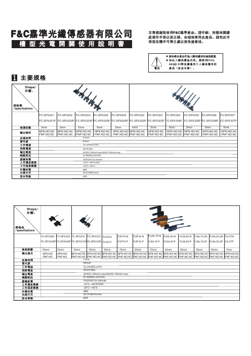
5 光軸位置
6 连接器类型
5mm NPN.NO.NC PNP.NO.NC
5mm NPN.NO.NC PNP.NO.NC
FC-SPX308 FC-SPX309 FC-SPX310 FC-SPX315 FU30-N FC-SPX308P FC-SPX309P FC-SPX310P FC-SPX315P FU30-P
FUP15-N FUP15-P
0.3mm
940um
12~24VDC±10% 30mA Max
30VDC 200mA max/240AC 500mA max 20 MΩMin.500VDC
1000VAX for lminute
-35℃~+85℃CRH
-25℃~+60℃
ABS Φ3.0×2M/4cores Ip66
Φ2.8 四芯 2000mm
FUP30-N FUAL15-N FUAL30-N FUAL50-N FUAL15-2N FUAL30-2N FU-07N FUP30-P FUAL15-P FUAL30-P FUAL50-P FUAL15-2P FUAL30-2P FU-07P
10mm NPN.NO PNP.NO
10mm NPN.NO PNP.NO
30mA Max
30VDC 200mA max/240AC 500mA max 20 MΩMin.500VDC
1000VAX for lminute -360℃
ABS Φ3.0×2M/4cores
Ip66
5mm NPN.NO.NC PNP.NO.NC
5mm
5mm
NPN.NO.NC NPN.NO.NC PNP.NO.NC PNP.NO.NC
槽型光電開關使用說明書
F5021说明手册(新版)

第三章
参数介绍 ...................................................................................................................... 33
3.1 参数表 ...............................................................................................................................................................33 3.2 参数设置说明: ...............................................................................................................................................36
1.书脊 2.每章首页只放题目 3.每章加黑色块 4.线路板调深(黑白效果好)
目
第一章 第二章
录
功能介绍 ........................................................................................................................ 3
397第一章功能介绍11功能列表编号备注编号名称备注标准功能st提前开门操作配置sm11a板群控运行10重复开门10上班高峰服务11换站停靠11下班高峰服务12错误指令取消12分散待梯13反向时自动消指令13小区监控14直接停靠14远程监控15满载直驶15轿厢到站钟16待梯时轿内照明风扇自动断电16厅外到站预报灯17自动返基站17厅外到站钟18液晶显示界面操作器18轿厢ic卡楼层服务控制19模拟量速度给定19厅外ic卡呼梯服务控制20数字量速度给定20前后门独立控制21故障历史记录21强迫关门22井道层楼数据自学习22vip贵宾层服务23服务层的任意设置23密码层控制功能24层楼显示字符设置24开关控制单梯服务层切换25司机操作25开关控制群控梯服务层切换26独立运行26开关控制操纵厢按钮非服务层设置27点阵式层楼显示器27停电应急平层28滚动显示运行方向28大楼后备电源运行29自动修正层楼位置信号29地震操作30锁梯服务30语音抱站功能31门区外不能开门的保护3132门光幕保护3233超载保护3334轻载防捣乱3435逆向运行保护3536防打滑保护3637防溜车保护37pdf文件使用试用版本创建www
FC-20AR-E简要操作手册0
无锡市信捷科技电子有限公司
第一章功能简介一、基本性能
●逻辑控制,模拟量输入输出集于一体
开关量输入:10点(NPN型光耦隔离)
开关量输出:10点(继电器型)
温度模拟量输入:3点(铂电阻PT100),
电流模拟量输入:3点(4~20mA)
●结构简单,外观简洁大方美观,
●性价比高,大幅度节省了空间
二、一般规格
1、电气规格
2
三、输入输出规格
2、模拟量输入输出
温度模拟量输入:3路(PT100)
电流模拟量输入:3路(4~20mA)1)基本参数表
第二章编程及应用
一、编程指令
PLC编程参照《FC系列可编程控制器操作手册》
二、模拟量对应寄存器对照表
温度模拟量输入电流模拟量输入。
OMRON光电传感器操作手册
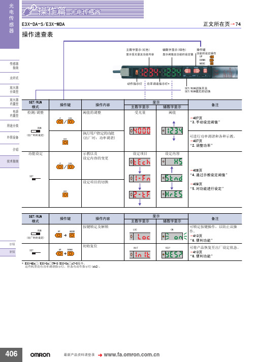
䗝ᢽᖂߚ䖍㓬 ऩջ䖍㓬˖ǃϸջ䖍㓬˖ 䗝ᢽᖂߚࡼᯊ ᖂߚડᑨᯊ䯈 ऩջ䖍㓬ĂõV˖ǃµV˖ǃPV˖ǃPV˖ǃPV˖ ϸջ䖍㓬ĂõV˖ǃµV˖ǃPV˖ǃPV˖ǃPV˖ $7&䫭䇃䕧ߎ˖ ҙ$7&ൟ ᣝ䗮䘧䕧ߎ˖ǃ ফܝㄝ㑻Ͼ䯜ؐП䯈ᯊ䕧ߎ˖ 㞾䆞ᮁ䕧ߎ˖ $7&ࡳ㛑᳝ᬜ˖ǃ $7&ࡳ㛑᮴ᬜ˖ ᮴䆒ᅮ˖ǃ$7&ⱘᓔྟ໘⧚˖ǃ ࡳ⥛䇗䇤ˇ$7&ⱘᓔྟ໘⧚˖
581
䆒ᅮ㒧ᴳৢˈ䖨ಲࠄ ᪡ࠡⱘᰒ冫
581
㟇581
㟇581
408
᳔ᮄѻક䌘᭭䇋ⱏᔩ
᪡㆛⬉ܝӴᛳ఼
ܝ ⬉ Ӵ ᛳ ఼
䆒ᅮࡳ㛑 6(7ᓣ
䗮⫼gᷛ䆚Ẕ⌟ൟ
(;'$ƶ6
ࡳ㛑ߛᤶᯊ᠔ᰒ冫ⱘݙᆍЎߎॖᯊⱘ䆒㕂DŽ ḍ䆒ᅮⱘݙᆍˈࡳ㛑ߛᤶЁৃ㛑Ӯࡴᮄⱘ乍ⳂDŽ
℆581⢊ᗕϟߛᤶᓣᯊ
ঠ䕧ߎ
℆ߛᤶϾ䗮䘧ⱘ䕧ߎݙᆍᯊ
⫼䗨ߚ㉏ ೈ䆒 ҟ㒡 ᡔᴃᣛफ
℆ߛᤶ$7&ࡳ㛑᳝ᬜ᮴ᬜᯊ
ҙ$7&ൟ 䆒ᅮᅠ៤ৢ
ᇚ6(7581ߛᤶᓔ݇䆒Ў 581 DŽ
581
ࡳ㛑ϔ㾜 াࣙᣀҢ䗮⫼ൟᓔྟᮄⱘࡳ㛑DŽᴀࡳ㛑䚼ߚ䇋খ䯙䗮⫼ൟDŽ
83 '2:1
䗮䖛Āߛᤶᰒ冫āࡳ㛑ᬍᰒ冫ᮍ⊩ᯊˈ䗮䖛䬂᪡ᇚ䕙ࡽ᭄ᄫᰒ冫 ߛᤶЎ䯜ؐDŽ
ᡔᴃ㆛ ᪡㆛
䆶⬉䆱800-820-4535
407
ܝ ⬉ Ӵ ᛳ ఼
᪡㆛⬉ܝӴᛳ఼
䗮䖛冫ᬭ䆒ᅮ䯜ؐ 6(7ᓣ
冫ᬭⱘᮍ⊩ˈ᳝བϟಯ辵DŽՓ⫼ᯊ䇋䗝ᢽ᳔ড়䗖ⱘᮍ⊩DŽ 581ᓣϟг㛑䖯㸠冫ᬭ ҙᎹӊ᳝᮴冫ᬭǃ㞾ࡼ冫ᬭ DŽ ᪡ᮍ⊩䇋খ䯙ѻક䰘ᏺⱘĀՓ⫼䇈ᯢкāDŽ ᔧ䕙ࡽ᭄ᄫᰒ冫ߎ⦄Ā29(5āǃĀ/2āǃĀ1($5āᯊˈ㸼冫ߎ䫭DŽ 䇋䞡ᮄ䇗㡖ᑊ䆒ᅮDŽ
光电开关传感器说明书
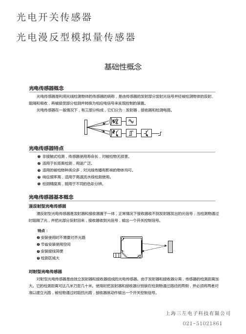
光电开关传感器 光电漫反型模拟量传感器
特点: 1 长距离检测,高精度检测 2 可检测小物体 3 不受被检物的形状、颜色和材质影响 4 适用恶劣工作环境
回归反射型光电传感器 回归反射型光电传感器是把发射器和接收器装入同一个装置内,在其前方装一块反光板,利用反射原理完成光电
控制作用的光电传感器。正常情况下,发射器发出的光被反光板反射回来被接收器收到;一旦光路被检测物挡住,接 收器检测的光信号有变化,光电传感器就动作,输出一个开关控制信号。
特点: 1 安装使用时便于光路对齐 2 相对于对射式光电传感器,节省安装使用空间 3 安装接线简便 4 不受被检物的形状、颜色和材质影响
上海三左电子科技有限公司 021-51021861
光电开关传感器 光电漫反型模拟量传感器
应用实例
光电式传感器主要利用光电效应检测物体。 在环境条件比较好、无粉尘污染的场合,可采用光电式传感器。 光电式传感器有检测距离远,对被检测物无影响的特性,广泛用于电子行业、食品饮料行业、包装物流行业等。
检测集成电路块
规格表中的检测距离是在检测目标为100*100mm、200*200mm、300*300mm的白色无光泽纸的条件下测得。
对射型 将发射器和接收器面对面安装,并连接电源。 调节发射器和接收器的上下左右位置,使中心对正,使指示灯状态变化。 可靠安装两者后并校对使其检测到目标。
发射器
回归反射型(包括偏振反射型) 将传感器和反光板镜面对面安装后,连接电源。 调节反射面的上下左右位置,传感器的指示灯状态变化。 可靠安装两者后并校对并使其检测到目标。
光电开关传感器
光电漫反型模拟量传感器
基础性概念
光电传感器概念
5200说明书
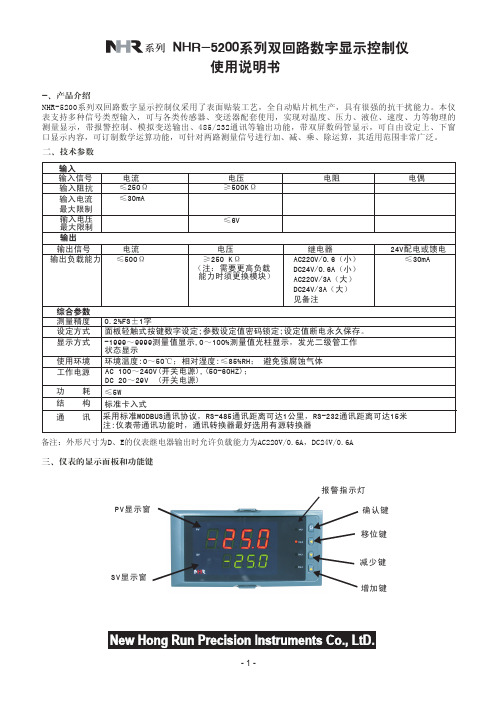
五、通电设置 仪表接通电源后,即进入自检状态,自检完毕后,仪表自动转入工作状态,在工作状态下,按压 键显示LOC, LOC参数设置有如下: 1、1) Loc等于任意参数可进入一级菜单(LOC=00;132时无禁锁); 2) Loc=132,按压 键4秒可进入二级菜单; 3) Loc=130,按压 键4秒可进入时间设置菜单;对于带打印功能的表. 4) Loc等于其他值,按压 键4秒退出到测量画面。 2、如果Loc=577,在Loc菜单下,同时按住 键和 键达4秒,可以将仪表的所有参数恢复到出厂默认设置。 3、在其它任何菜单下,按压 键4秒秒可退出到测量画面。 4、采用热电偶信号输入时,通道小数点dP=0时,温度显示分辨率为1℃;dP=1时,温度显示分辨率为0.1℃, (1000℃以上自动转为1℃分辨率)。 5、时间设定 在仪表PV显示测量值的状态下,按压 键进入参数,设定LOC=130,在PV显示LOC,SV显示130的状态下,按压 键4秒,即进入时间参数设定,仪表PV显示"dATE",SV显示当前日期(如:090720-2009年7月20日),在此状态下 ,可参照仪表参数设定方法,设定当前日期。在仪表当前日期显示状态下,按压 键,仪表PV显示"TlnE",仪表 SV将显示当前时间(如183047 -18点30分47秒),在此状态下,可参照仪表参数设定方法,设定当前时间。在仪 表当前时间显示状态下,再次按压 键,则退出时间设定,回至PV测量值显示状态。
设定定时打印的间隔时间(小于10分钟则不打印) (无此功能时,无此参数)
PR-u 打印单位
0~45
参见单位设定功能代码表 (无此功能时,无此参数)
1PN
0~35
第一路输入分度号
第一路设定输入分度号类型(见选型表)
1DP 第一路小数点
DP5020_V2

OFF ON OFF ON OFF ON OFF ON
OUT15 SDO
Don't Csre
●
OFF ON
图5
(2) 极限参数(1)
参数名称
电源电压 输入端电压范围 输出端电流(DC) 输出端电压范围 时钟频率 工作温度范围 储存温度范围 SDI,CLK,LE,OE OUT0~OUT15 OUT0~OUT15,SDO CLK,SDI,LE,OE
外部应用框图
适用领域: 户内、外,单、双、全彩(动态、静态)LED显示屏 灯饰、节能照明
VLED VLED VLED VLED
●
●
●
●
●
●
●
●
●
●
●
●
OUT0 DATA CLK LE OE SDI CLK LE OE R-EXT
Riref
.
●
●
●
OUT15 SDO VCC VCC GND
输出及输入等效电路
VCC VCC VCC CLK SDI GND GND VCC
LE
OE
SDO
GND
GND
OUTn
GND
图4
集成电路系静电敏感器件,在干燥季节或者干燥环境使用容易产生大量静电,静电放电可能 会损坏集成电路,建议采取一切适当的集成电路预防处理措施,不正当的操作和焊 接,可能会造成 ESD 损坏或者性能下降, 芯片无法正常工作。
参数符号
VCC VIN IOUT VOUT FCLK Torp Ttsg
极限值
-0.4~6.0 -0.4~VCC+0.4V 65 -0.4~+6.0 25 -40~+85 -55~+150
布尔夫光电感应器产品参考指南说明书
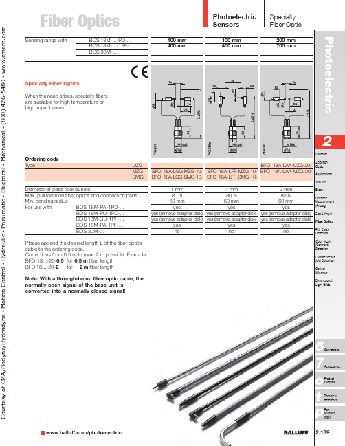
Fiber Optics2.139/photoelectricp76o Please append the desired length L of the fiber optics cable to the ordering code.Corrections from 0.5 m to max. 2 m possible. Example:BFO 18...-20-0.5for 0.5 m fiber length BFO 18...-20-2for 2 m fiber length Note: With a through-beam fiber optic cable, the normally open signal of the base unit is converted into a normally closed signal!Sensing range withBOS 18M-...-PD-...BOS 18M-...-1PF-...BOS 30M-...Ordering codeT ype UZG MZG SMG Diameter of glass fiber bundleMax. pull force on fiber optics and connection parts Min. bending radius For use with BOS 18M-PA-1PD-...BOS 18M-PU-1PD-...BOS 18M-GU-1PF-...BOS 18M-PA-1PF-...BOS 30M-...Specialty Fiber OpticsWhen the need arises, specialty fibers are available for high temperature or high impact areas.C o u r t e s y o f C M A /F l o d y n e /H y d r a d y n e ▪ M o t i o n C o n t r o l ▪ H y d r a u l i c ▪ P n e u m a t i c ▪ E l e c t r i c a l ▪ M e c h a n i c a l ▪ (800) 426-5480 ▪ w w w .c m a f h .c o mPhotoelectric Sensors2.140Please append the desired length L of the fiber optics cable to the ordering code.Corrections from 0.5 m to max. 2 m possible. Example:BFO 18...-20-0.5for 0.5 m fiber length BFO 18...-20-2for 2 m fiber length Note: With a through-beam fiber optic cable, the normally open signal of the base unit is converted into a normally closed signal!SpecialtyFiber OpticSensing rangeBOS 18M-...-PD-...BOS 18M-...-1PF-...BOS 30M-...Ordering codeT ype UZG MZG SMGDiameter of glass fiber bundleMax. pull force on fiber optics and connection partsMin. bending radiusFor use with BOS 18M-PA-1PD-...BOS 18M-GU-1PF-...BOS 18M-PA-1PF-...BOS 30M-...C o u r t e s y o f C M A /F l o d y n e /H y d r a d y n e ▪ M o t i o n C o n t r o l ▪ H y d r a u l i c ▪ P n e u m a t i c ▪ E l e c t r i c a l ▪ M e c h a n i c a l ▪ (800) 426-5480 ▪ w w w .c m a f h .c o mFiber Optics/photoelectric Sensing Range BOS 18M-...-PD-.../BOS 18M-...-1PF-...DiffuseBOS 30M-...RetroreflectiveBOS 18M-...-PD-.../BOS 18M-...-1PF-...BOS 30M-...Ordering code TypeUZG MZG SMGDiameter of glass fiber bundleMax. pull force on fiber optics and connection parts Min. bending radiusFor use with BOS 18M-PA-1PD-...BOS 18M-GU-1PF-...BOS 18M-PA-1PF-...BOS 30M-...Sn BOS 18M-PA-1PD-...with BOS 18M-...-1PF-...BOS 30M-...Range with BOS 18M-PA-1PD-...with BOS 18M-...-1PF-...BOS 30M-...Sensing distances referenced to Kodak gray card 90 %Reflexion.Diffuse with glass fiber optics used as retroreflective:Ranges are referenced to BOS R-1 reflector.When using as a retroreflective type, twice the sensing distance must be used as the object dead zone.Please append the desired length L of the fiber optics cable to the ordering code!Corrections from 0.5 m to max. 2 m possible.Example:BFO 18...-30-0.5for 0.5 m fiber length BFO 18...-30-2for 2 m fiber lengthC o u r t e s y o f C M A /F l o d y n e /H y d r a d y n e ▪ M o t i o n C o n t r o l ▪ H y d r a u l i c ▪ P n e u m a t i c ▪ E l e c t r i c a l ▪ M e c h a n i c a l ▪ (800) 426-5480 ▪ w w w .c m a f h .c o mPhotoelectricSensors2.142Specialty Fiber OpticSensing Range BOS 18M-...-PD-.../BOS 18M-...-1PF-...DiffuseBOS 30M-...RetroreflectiveBOS 18M-...-PD-.../BOS 18M-...-1PF-...BOS 30M-...Ordering code TypeUZG MZG SMGDiameter of glass fiber bundleMax. pull force on fiber optics and connection parts Min. bending radiusFor use with BOS 18M-PA-1PD-...BOS 18M-GU-1PF-...BOS 18M-PA-1PF-...BOS 30M-...Sn BOS 18M-PA-1PD-...with BOS 18M-...-1PF-...BOS 30M-...Range with BOS 18M-PA-1PD-...with BOS 18M-...-1PF-...BOS 30M-...Installation notethe adapter disk from the fiber optic cable !C o u r t e s y o f C M A /F l o d y n e /H y d r a d y n e ▪ M o t i o n C o n t r o l ▪ H y d r a u l i c ▪ P n e u m a t i c ▪ E l e c t r i c a l ▪ M e c h a n i c a l ▪ (800) 426-5480 ▪ w w w .c m a f h .c o mFiber Optics/photoelectric Rugged construction from the outside in UZG type Polyurethane jacket Strain reliefGlass fiber bundle -Enhanced chemical resistance -High flexibility -Does not get brittle in oils or coolantsMZG type Polyurethane jacket Strain reliefGlass fiber bundle -High temperature rating (-20...+170°C)-Crush resistant -Resistant to hot chipsBalluff BFO 18M series fiber optic cables are designed for use with BOS 18M and BOS 30M sensors. These rugged-duty cables are ideal for applications where high excess gain, enhanced chemical resistance, or high temperature solutions are needed.BOS 18M-GU-1PF-...BOS 18M-PU-1PD-...See Tubular section for technical dataBFO 18M SeriesC o u r t e s y o f C M A /F l o d y n e /H y d r a d y n e ▪ M o t i o n C o n t r o l ▪ H y d r a u l i c ▪ P n e u m a t i c ▪ E l e c t r i c a l ▪ M e c h a n i c a l ▪ (800) 426-5480 ▪ w w w .c m a f h .c o m。
ICP DAS ACS-20-MRTU 无触摸红外传感器开关说明书

User ManualVersion 1.1 Feb 2021ACS-20B(W)-MRTU No-touch Infrared Sensor SwitchWritten by Bruce HsuEdited by Kalia HuangTable of Contents1.Introduction (6)1.1Features (7)2.Hardware (8)2.1Specifications (8)2.2Appearance (9)2.3Pin assignments (10)2.4LED Indicators (11)3.Configured by Hardware (12)3.1Relay Hold Time (12)3.2Toggle Switch Mode (13)3.3Sensing Range (13)3.4Restore Default Communication Settings (14)4.Configured by Software (15)4.1ACS-20 Utility (15)4.2Serial Communication (16)4.3Test Locked Mode (17)4.4Set Relay Hold Time (17)4.5Set Toggle Mode (18)4.6Invert Red/Blue LED (18)4.7Set RTC (19)4.8Set IR Sensing Record Mode (20)4.9Set Locked Periods (20)4.10Access All Settings (21)4.11Configuration File (22)5.Modbus Command (23)5.1Modbus Register Table (24)5.1.1Modbus Input Registers (24)5.1.2Modbus Holding Registers (25)5.2Modbus FC100 Commands (26)5.2.1Sub-FC00 (0x00): Get the Module Name (27)5.2.2Sub-FC04 (0x04): Set the Modbus Unit ID (Net ID) (28)5.2.3Sub-FC05 (0x05): Get Communication Settings (29)5.2.4Sub-FC06 (0x06): Set Communication Settings (30)5.2.5Sub-FC07 (0x07): Read Current Communication Settings (31)5.2.6Sub-FC08 (0x08): Get Modbus Response Delay (32)5.2.7Sub-FC09 (0x09): Set Modbus Response Delay (33)5.2.8Sub-FC32 (0x20): Get Firmware Version (34)5.2.9Sub-FC33 (0x21): Get Firmware Date (35)5.2.10Sub-FC34 (0x22): Get Stored Quantity of IR Sensing Records (36)5.2.11Sub-FC35 (0x23): Clear All Stored IR Sensing Records (37)5.2.12Sub-FC39 (0x27): Get RTC Time (38)5.2.13Sub-FC40(0x28): Set RTC Time (39)5.2.14Sub-FC41(0x29): Get IR Sensing Record Data (40)5.2.15Sub-FC42(0x2A): Get IR Sensing Record Mode (41)5.2.16Sub-FC43(0x2B): Set IR Sensing Record Mode (42)5.2.17Sub-FC44(0x2C): Get Inverted Red/Blue LED Status (43)5.2.18Sub-FC45(0x2D): Set Inverted Red/Blue LED Status (44)5.2.19Sub-FC46(0x2E): Get Relay Hold Time (45)5.2.20Sub-FC47(0x2F): Set Relay Hold Time (46)5.2.21Sub-FC64(0x40): Get Locked Mode (47)5.2.22Sub-FC65(0x41): Set Locked Mode (48)5.2.23Sub-FC66(0x42): Get Day Mode of Locked Periods (49)5.2.24Sub-FC67(0x43): Set Day Mode of Locked Periods (50)5.2.25Sub-FC68(0x44): Get Enabled State of Locked Periods (51)5.2.26Sub-FC69(0x45): Set Enabled State of Locked Periods (52)5.2.27Sub-FC70(0x46): Get 8 Locked Periods (53)5.2.28Sub-FC71(0x47): Set 8 Locked Periods (54)5.2.29Sub-FC72(0x48): Get Enabled State of Locked Period Function (55)5.2.30Sub-FC73(0x49): Set Enabled State of Locked Period Function (56)5.2.31Sub-FC76(0x4C): Get Scale Value of Rotary Switch (57)5.2.32Sub-FC77(0x4D): Get Toggle Mode (58)5.2.33Sub-FC78(0x4E): Set Toggle Mode (59)5.2.34Sub-FC165(0xA5): Reboot Module (60)Appendix A. Update Firmware (61)Appendix B. Revision History (63)Important InformationWarrantyAll products manufactured by ICP DAS are under warranty regarding defective materials for a period of one year, beginning from the date of delivery to the original purchaser.WarningICP DAS assumes no liability for any damage resulting from the use of this product.ICP DAS reserves the right to change this manual at any time without notice. The information furnished by ICP DAS is believed to be accurate and reliable. However, no responsibility is assumed by ICP DAS for its use, not for any infringements of patents or other rights of third parties resulting from its use.CopyrightCopyright @ 2021 by ICP DAS Co., Ltd. All rights are reserved.TrademarkNames are used for identification purpose only and may be registered trademarks of their respective companies.Contact us1. IntroductionFigure 1-1 ACS-20B(W)-MRTU application architecture The No-touch Infrared Sensor Switch from ICP DAS can be used to open a door using palm induction, which makes it more convenient when entering or exiting a room or building. The inductive distance and the delay time for door opening are adjustable, and has red and blue indicator lights to show the status of the switch. As people enter and exit the door using the No-touch Infrared Sensor Switches, a time stamp recording the action can be simultaneously logged.The No-touch Infrared Sensor Switch includes an RS-485 interface and provides Modbus RTU communication, which can remotely enable/disable the switch and get the induction time records by the access control system.Additionally, the No-touch Infrared Sensor Switch is not only used for the access control system but also helps you control other electronic devices. While it is triggered in toggle mode at the first time, the switch outputs ON signal, and next time outputs OFF signal.The No-touch Infrared Sensor Switch can be used with electric doors to prevent issues related to the spread of infectious bacteria via touch. The switches can be used in medical institutions, retail stores, the food industry, industrial plants, and offices, etc. to provide an excellent sanitary environment.1.1 Features◼[ACS-20B-MRTU / ACS-20W-MRTU]◆Special infrared code to against interference◆Multiple operating modes: Sensing/Standby, Lock, Toggle Switch.◆Provides 8 locked periods each day◆Double-color status indicator◆Induction distance: 1 ~ 12 cm◆With Relay (N.C. and N.O. output)◆Relay hold time: 0.5 ~ 20 sec◆The switches time recording: 1,600 records◆Communication interface and protocol: RS-485/Modbus RTU◼[Applications]◆ Surveillance system◆ Home and building automation◆Medical institutions◆Retail stores◆Food industry2. Hardware2.1 SpecificationsTable 2-1: Specification Table2.2 AppearanceFigure 2-1: ACS-20B-MRTU.Figure 2-2: ACS-20W-MRTU2.3 Pin assignments◼TerminalsFigure 2-3: ACS-20B(W)-MRTU terminals◼CablesTable 2-2: Cables for ACS-20B(W)-MRTU terminalCablesPicture Model. Description InterfaceCA-014+Vs (Red)(+10~+30VDC)Power GND (Black)-CA-012NO (Blue)Relay COM (White)NC (Green)CA-019DATA+(Green)RS-485 DATA- (黃)2.4 LED IndicatorsThere are circular red and blue led indicators on the ACS-20B/W-MRTU to show different operating states. The meanings of these states are described in Table 2-3.Figure 2-4: Red/Blue LED indicators of ACS-20B(W)-MRTUTable 2-3: Red/Blue LED indicators corresponding to module status LED Circular LED Indicator ACS-20B(W)-MRTU StatusRed Blue Red LED ON (NC & COM contacted) (*)Standby; Toggle mode (ON) Blue LED ON (NO & COM contacted) (*)IR sensing; Toggle mode (OFF) Red LED blinks once per 2 seconds Locked modeRed & blue LED blink 2 times per second Firmware update mode* The module status inverted if red and blue LEDs are inverted.3. Configured by Hardware3.1 Relay Hold TimeRelay hold time (off-delay time) after IR sensing can be set by the scale position “0~C” of the rotary switch (figure 3-1) as shown in table 3-1.Figure 3-1: Scale 0~C of rotary switch for relay hold timeTable 3-1: relay hold time to the scale of the rotary switchscale Relay hold time (sec)0 0.51 12 23 34 45 56 67 78 89 9A 10B 15C 203.2 Toggle Switch ModeRotate the rotary switch to the scale ‘D’ to be in the hardware Toggle Switch Mode. In this mode, sense the ACS-20B(W)-MRTU by hand once, the circular red LED is changed to blue (Relay: NO & COM contact). Then, sense the ACS-20B(W)-MRTU by hand once again, the blue LED will be changed back to red. (Relay: NC & COM contact)Figure 3-2: Scale 0~C of rotary switch for relay hold time3.3 Sensing RangeSensing range (sensed by palm of the hand) of ACS-20B(M)-MRTU can be adjusted by the rotary knob in figure 3-3. Rotate the knob clockwise to extend the sensing range (maximum 12 cm). Rotate the knob counterclockwise to reduce the sensing range (minimum 1 cm around). The scale is not linear between minimum and maximum limit. The default scale is rotated clockwise to the maximum limit.Figure 3-3: Rotary knob for sensing range (sensed by palm)3.4 Restore Default Communication SettingsRotate the rotary switch to the scale ‘E’. Power cycle the module to restore the default serial communication (Table ).Figure 3-4: Rot ate the rotary switch to ‘E’ scale for default communication.Table 3-2: relay hold time to the scale of the rotary sItem Default valueBaud Rate 9600 bpsParitys NoneData Bits 8Stop Bits 1Modbus Response Delay 1 msModbus Net ID 14. Configured by Software4.1 ACS-20 UtilityACS-20 Utility is the configuration tool for ACS-20B(W)-MRTU. It runs in .NET Framework 4.5 based on Microsoft Windows OS. Users can download the ACS-20 Utility from:ACS-20 Utility (ACS20_Util_Setup_v#i#i#i#.zip)https:///en/download/show.php?num=3154&model=ACS-20B-MRTUIf the .NET Framework 4.5 is not available on the Microsoft OS, the setup package will download and install the redistribution automatically. The redistribution package can also be downloaded from the following link:https:///en-US/download/details.aspx?id=306534.2 Serial CommunicationThe initial window of the ACS-20 utility is shown in the left of figure 4-1. Select the COM port of the host PC and the communication parameters of ACS-20B(W)-MRTU. Go to the main configuration window by clicking the “Connect” button.Figure 4-1: Configuration window for ACS-20B(W)-MRTU.I f the main configuration window is opened by the “Open Interface” button, click menu [Connect]=>[Connect ACS-20-MRTU] to open the connection window as shown in figure 4-2.Figure 4-2: Connection window for the main configuration window.S et the communication parameters by clicking the “Set” button in the Communication Settings section in figure 4-3. Refer to chapter 5 for related Modbus command.Figure 4-3: Set communication settings.4.3 Test Locked ModeIn the “IR Sensing” section of the utility, click “Lock” and “Unlock” button (figure 4-4) to test the locked mode. IR sensing function is disabled in this mode. Refer to chapter 5 for related Modbus command.Figure 4-4: T est locked mode.4.4 Set Relay Hold TimeIn the “IR Sensing” section of the utility, there are “0.5 ~ 20 sec” items in the “Relay Hold Time” combobox (figure 4-5) for selection. Click the “Set” button to set the paramter. Refer to chapter 5 for related Modbus register and command.Figure 4-5: Set relay hold time.4.5 Set Toggle ModeIn the “IR Sensing” section of the utility, click the “Set” button after checking or unchecking the “Toggle Mode” checkbox as shown in figure 4-6. Refer to chapter 5 for related Modbus register and command.Figure 4-6: Set toggle mode.4.6 Invert Red/Blue LEDIn the “IR Sensing” section of the utility, click the “Set” button after checking or unchecking the “Invert Red/Blue LED” checkbox as shown in figure 4-7. Refer to chapter 5 for related Modbus register and command.Figure 4-7: Set inversion of Red/Blue LED.4.7 Set RTCThere is built-in RTC (Real Time Clock) in ACS-20B(W)-MRTU. One RTC Time (Year/Month/Day, Hour:Minute:Second) is recorded when IR sensing by palm of hand.I n the “Set RTC” section(figure 4-8) of the utility, the time following the “System Time” radio button is the host system time. Customize the t ime by clicking the “Custom Time” radio button. Click the “Set” button to set RTC with the tiime folowing the selected radio button. Refer to chapter 5 for the related Modbus command to access RTC.Figure 4-8: Set RTC4.8 Set IR Sensing Record ModeThe “Record Mode” in the “IR Sensing Records in Storage ” section (figure 4-9) is for setting the storage mode when the storage is full. There are two modes:Mode 0 (Store from start): (default) Clear all records and store from start. Mode 1 (Discard the latest): Discard new data and keep 1600 records of old data.Figure 4-9: Set IR sensing record mode.4.9 Set Locked PeriodsLocked periods can be set in the “Locked Periods Settings” section of the utility as shown in figure 4-10. The module goes into locked mode (no IR sensing) in the locked period.Figure 4-10: Set locked periods.◆♦⌧⍓(1) Check/Uncheck “Enabled Locked Periods Function” checkbox to enable/disable thisfunction.(2) C lick the “Locked Periods” combobox to select 8 periods (0 ~ 7) for setting. The “EndTime” should be more than the “Start Time”.(3) C lick “Enable Every Day Mode” or “Enable Week Day Mode” radio button for “Every DayMode” or “Week Day Mode”.(4) This combobox can set the locked periods for every day and weekdays (Sunday toSaturday) by checking or unchecking the P0 ~ P7 checkboxes to enable or disable them.(5) Click the righ t “Set” button to finish the setting.4.10 Access All SettingsSeparate settings can be set as previous sections. Or click Menu [Settings]=>[Download All Settings to the ACS-20-MRTU] to set all settings to the module at once after all parameters are selected in the utility.Click Menu [Settings]=>[Load All Settings from the ACS-20-MRTU] to read back all settings to utility from the module at once.Figure 4-11: Access all setting of the module.4.11 Configuration FileAll settings in the utility can be saved to a configuration file by clicking Menu [File]=>[Save Settings to File(*.dat)] where the file extension is dat.Load all setting from a configuration file by clicking Menu [File]=>[Load Settings from File(*.dat)]Figure 4-12: Access configuration file.5. Modbus CommandThe following Function Code commands () are provided for a Modbus master to configure ACS-20B(W)-MRTU. FC3, FC4, and FC6 are the standard Modbus commands for Modbus masters to access the Modbus registers. Sub-FC commands of FC100 are manufacturer assigned commands for parameter settings on the module.Table 5-1: Modbus Function Code for ACS-20B(W)-MRTU5.1 Modbus Register TablePlease refer to table 5-2 and table 5-3 for the Modbus Input Registers (3xxxx) and Modbus Holding Registers (4xxxx). Settings written to the Modbus holding registers are all volatile for ACS-20B(W)-MRTU. The values will go back to the default or previous ones after power cycling. The settings can be kept (non-volatile) by the FC100 commands in section 5.2.5.1.1 Modbus Input RegistersThe Modbus Input Registers are listed in Table 5-2. They are read-only registers.Table 5-2: Modbus Input Registers (3xxxx)5.1.2 Modbus Holding RegistersThe Modbus Holding Registers are listed in Table 5-3. The access is read and write. Write values to the holding registers can change settings immediately but restore to previous ones after power cycling the module.Table 5-3: Modbus Holding Registers (4xxxx)5.2 Modbus FC100 CommandsThis section describes all sub function calls (sub-FC) of FC100 (0x64) for the settings on ACS-20B(W)-MRTU. All sub-FCs are listed in table 5-4. All setting values are non-volatile (effective after power-cycling the module). In the following sections, Modbus requests and responses are listed without CRC16 bytes.Table 5-4: Sub-FCs of FC1005.2.1 Sub-FC00 (0x00): Get the Module NameThe request/response for getting the module name is listed in table 5-5 and table 5-6.Table 5-5: FC100-Sub-FC00 RequestTable 5-6: FC100-Sub-FC00 Response5.2.2 Sub-FC04 (0x04): Set the Modbus Unit ID (Net ID)Table 5-7: FC100-Sub-FC04 RequestTable 5-8: FC100-Sub-FC04 ResponseNote: This parameter setting is effective after power cycling the module,5.2.3 Sub-FC05 (0x05): Get Communication SettingsTable 5-9: FC100-Sub-FC05 RequestTable 5-10: FC100-Sub-FC05 Response5.2.4 Sub-FC06 (0x06): Set Communication SettingsTable 5-11: FC100-Sub-FC06 RequestTable 5-12: FC100-Sub-FC06 Response5.2.5 Sub-FC07 (0x07): Read Current Communication SettingsThe settings read from Sub-FC05 is the settings by Sub-FC06 if the Byte 09 [Change Setting] of Sub-FC06 is 0 (The settings are effective after power-cycling). Sun-FC07 reads the settings before power-cycling the module.Table 5-13: FC100-Sub-FC07 RequestTable 5-14: FC100-Sub-FC07 Response5.2.6 Sub-FC08 (0x08): Get Modbus Response DelayTable 5-15: FC100-Sub-FC08 RequestTable 5-16: FC100-Sub-FC08 Response5.2.7 Sub-FC09 (0x09): Set Modbus Response DelayTable 5-17: FC100-Sub-FC09 RequestTable 5-18: FC100-Sub-FC09 Response5.2.8 Sub-FC32 (0x20): Get Firmware VersionTable 5-19: FC100-Sub-FC32 RequestTable 5-20: FC100-Sub-FC32 Response5.2.9 Sub-FC33 (0x21): Get Firmware DateTable 5-21: FC100-Sub-FC33 RequestTable 5-22: FC100-Sub-FC33 Response5.2.10 Sub-FC34 (0x22): Get Stored Quantity of IR Sensing RecordsTable 5-23: FC100-Sub-FC34 RequestTable 5-24: FC100-Sub-FC34 Response5.2.11 Sub-FC35 (0x23): Clear All Stored IR Sensing RecordsTable 5-25: FC100-Sub-FC35 RequestTable 5-26: FC100-Sub-FC35 Response5.2.12 Sub-FC39 (0x27): Get RTC TimeTable 5-27: FC100-Sub-FC39 RequestTable 5-28: FC100-Sub-FC39 Response5.2.13 Sub-FC40(0x28): Set RTC TimeTable 5-29: FC100-Sub-FC40 RequestTable 5-30: FC100-Sub-FC40 Response5.2.14 Sub-FC41(0x29): Get IR Sensing Record DataTable 5-31: FC100-Sub-FC41 RequestTable 5-32: FC100-Sub-FC41 ResponseNote: Data length of 1 record is 8 bytes([Year_MSB][Year_LSB][Month][Day][Hour][Minute][Second])5.2.15 Sub-FC42(0x2A): Get IR Sensing Record ModeTable 5-33: FC100-Sub-FC42 RequestTable 5-34: FC100-Sub-FC42 Response5.2.16 Sub-FC43(0x2B): Set IR Sensing Record ModeTable 5-35: FC100-Sub-FC43 RequestTable 5-36: FC100-Sub-FC43 Response5.2.17 Sub-FC44(0x2C): Get Inverted Red/Blue LED StatusTable 5-37: FC100-Sub-FC44 RequestTable 5-38: FC100-Sub-FC44 Response5.2.18 Sub-FC45(0x2D): Set Inverted Red/Blue LED StatusTable 5-39: FC100-Sub-FC45 RequestTable 5-40: FC100-Sub-FC45 Response5.2.19 Sub-FC46(0x2E): Get Relay Hold TimeTable 5-41: FC100-Sub-FC46 RequestTable 5-42: FC100-Sub-FC46 Response5.2.20 Sub-FC47(0x2F): Set Relay Hold TimeTable 5-43: FC100-Sub-FC47 RequestTable 5-44: FC100-Sub-FC47 Response5.2.21 Sub-FC64(0x40): Get Locked ModeTable 5-45: FC100-Sub-FC64 RequestTable 5-46: FC100-Sub-FC64 Response5.2.22 Sub-FC65(0x41): Set Locked ModeTable 5-47: FC100-Sub-FC65 RequestTable 5-48: FC100-Sub-FC65 Response5.2.23 Sub-FC66(0x42): Get Day Mode of Locked PeriodsTable 5-49: FC100-Sub-FC66 RequestTable 5-50: FC100-Sub-FC66 Response5.2.24 Sub-FC67(0x43): Set Day Mode of Locked PeriodsTable 5-51: FC100-Sub-FC67 RequestTable 5-52: FC100-Sub-FC67 Response。
光电传感器说明书)

规格(注1):(注2):(注3):(注4):如果串联连接5~8个放大器为50mA ,如果串联连接9~16个放大器为25mA 。
连接器型LS-401(P )没有装备外部输入。
H-SP 模式改变为其他模式后,当使用防干扰功能、收集的数据库载入/保存功能或复制功能时,再打开电源。
连接器型LS-401(P )不附带电缆。
请按下述使用另售单触电缆 。
母电缆(4芯):CN-74-C1(电缆长1m ),CN-74-C2(电缆长2m ),CN-74-C5(电缆长5m )子电缆(2芯):CN-72-C1(电缆长1m ),CN-72-C2(电缆长2m ),CN-72-C5(电缆长5m )注意事项●●●●●●●●●●●●●●●●请确认在电源关闭状态下进行接线和增设作业。
请确认电源电压在额定范围内变化。
请注意如果使用的电压超出额定范围,或直接连接AC电源,传感器可能烧坏或损坏。
如果在该传感器附近使用产生噪音的设备(开关调节器,转换发动机等),请将设备机架接地端子(F.G.)接地。
由于超长距离(U-LG)模式的灵敏度比其他模式更高,所以更容易受外部噪音影响。
确保使用前检查周围环境。
如果电源是市场上零售的开关调节器,请务必安装电源的机架接地端子(F.G.)接地。
电源接通后短时间(约0.5秒)内,请勿使用。
请注意短路或负荷的错误接线可能烧坏或损坏传感器。
请勿将电线与高压线或电源线一起或在同一管内拉线,这可能会由于感应而引起故障。
连接器型LS-401(P )必须使用另售单触电缆。
0.3mm 2以上电缆可延长至100m。
但为减少噪音,使接线尽可能短。
请勿用在屋外。
避免灰尘、污垢和水蒸气。
请勿将传感器与水、油、油脂或有机溶液,如稀释剂等直接接触。
此传感器不可在有易燃易爆气体的环境下使用。
不可拆卸或改装传感器。
MC-LS400 No.8137-00非常感谢您购买SUNX产品。
请仔细、完整阅读此使用说明书以便正确、合理地使用此产品。
请务必妥善保管此说明书。
布伦夫光电传感器产品指南说明书

1Khz High resolution/5Khz standard resolution
EASY touch Teach-in/Remote Teach-in
Байду номын сангаас
Yellow
2 bicolor Red/Green LEDs (SET and ERROR)
IP 67
ABS
Depends on fiber optics used
CE, cULus
M8 4-pin connector
2 m cable
4 x 26 AWG
C75 ANL-00-VY-050M
30 g
115 g
Wiring Diagrams
PNP
1
1
2
4
3
NPN
2
1
2
4
3
PNP
+V
3
Teach
0V
NPN
+V
4
Teach
0V
BN
+V
WH
Teach
BK
BU
0V
BN
+V
2
Contents Selection Guide Applications Tubular Block Distance Measurement (Analog) Slot & Angle Fiber Optics Full Color Detection Color Mark (Contrast) Detection Luminescence (UV) Detection Optical Windows Dimensional Light Grids
Supply Voltage Voltage Drop at Ud at Ie Rated Output Current Current Consumption Io (no load) Reverse Polarity Protection Short Circuit Protection Output Function Emitter Light Source Operating Temperature Range On/Off Delay (standard) Operating Frequency (max.) Sensitivity Adjustment Function Indication Contamination Indication Environmental Protection Housing Material Sensing Face Material Approvals Connection No. of wires & gauge Recommended Connector Weight
光电开关说明书

1PhotoelectricsRetro-reflective, Transistor Output Type PMR•Range: 10 m•Modulated, infrared light•Rated operational voltage: 10 to 40 VDC •Output: 200 mA, NPN or PNP•Make or break switching function (switch selectable)•Fully protected•LED-indication for target detected •High immunity to ambient light•25 x 65 x 81 mm reinforced PC housing, IP 67•Timer options (adjustable)Product DescriptionRetro-reflective photoelectric switch. Range up to 10 m.Fix ed sensitivity. High immu-nity to ambient light. Output function switch selectable.Protection degree IP 67.Screw terminal connection.25 x 65 x 81 mm polycarbo-nate housing. PG 13.5 or 1/2"NPT cable gland. Timer op-tions: Delay on operate, delay on release, one shot (triggered on leading or trailing edge).Type SelectionHousing Range Ordering no.Ordering no.Ordering no.Ordering no.W x H x DS nwithout timer without timer with timer with timer NPN PNP NPN PNP 25 x 65 x 81PG 13.5 cable gland 10 m PMR 10N G PMR 10P G PMR 10N GT PMR 10P GT 1/2" NPT cable gland10 mPMR 10N IPMR 10P IPMR 10N ITPMR 10P ITSpecificationsRated operating distance (S n )10 m (0 to 5,000 lux)With reflector type ER 4,ref. targetRated operational volt. (U B )10 to 40 VDC Ripple (U rpp )10%Output currentContinuous (I e )≤200 mA Short-time (I)200 mA,max. load capacity 100 nFNo load supply current ≤40 mA OFF-state current (I r )Max. 100 µA Voltage drop (U d )≤2.5 VDC Transient voltage IEC 947-5-2, level 3, 2.5 kV Dielectric voltage 2000 VAC rms (cont./supply)Sensitivity Fixed Light source GaAlAs, LED, 880 nm Light type Infrared, modulated Optical angle ±2°Light spot size 280 mm at 4 m Operating frequency 100 Hz Response time OFF-ON (t ON )≤4 ms ON-OFF (t OFF )≤6 msTime delay before avail. (t v )≤300 ms (typ. 100 ms)Output function Switch selectable, make or break switching IndicationTarget detected LED, yellow Optional timer Delay on operate 0.1 to 7 s ±2 s Delay on release 0.1 to 7 s ±2 s One shot 0.1 to 7 s ±2 sEnvironmentOvervoltage category III (IEC 664/664A; 947-1)Pollution degree 3 (IEC 664/664A; 947-1)Degree of protection IP 67 (IEC 529; 947-1)Temperature Operating -25°to +55°C (-13°to +131°F)Storage -30°to +80°C (-22°to +176°F)Vibration 10 to 150 Hz, 0.5 mm/7.5 g (IEC 68-2-6)Shock2 x 1 m & 100 x 0.5 m (IEC 68-2-32)Rated insulation voltage 50 VAC (rms)Electrical protectionShort-circuit, reverse polarity,overvoltage, transients2PMRSpecifications (cont.)Selection of FunctionSwitch 1 2 3PMR ... .PMR ... .T1 Break switching 9 One shot, leading edge - Break switching8 One shot, trailing edge - Make switching7 One shot, trailing edge - Break switching 5 Delay on release - Break switching 3 Delay on operate - Break switching 10One shot, leading edge - Make switching2 Make switching4 Delay on operate - Make switching 6 Delay on release - Make switching Don't careUpper postion ON (Mode 1)Lower position OFF (Mode 0)Housing material Body PC, grey Front PC, black CoverPC, blackCable glandPA, black, reinforced Mounting bracket Steel, blackConnection Screw terminal 5 x 2 x 1 mm 2Cable gland PG 13.5 or 1/2" NPT for cable 6 to 10 mm Weight90 gConnection DiagramTruth TableAccessoriesDelivery Contents•Photoelectric switch: PMR •Cable gland•Installation instruction •Mounting bracket•Packaging:Corrugated cardboard (environmentally friendly recycling material)•Reflectors: ER series•MB02 mounting bracket 90 mm long for mounting PMR from behind3PMROperation Diagramt = Time delaytv = Power ON delayDimensionsPMRPMR with angle bracketo r 1/2" N P TLED indication。
温润光电有限公司产品说明书:LIR30243型号高速响应红外光电开关

Jiangsu Wenrun Optoelectronic Co.,LTD Rev:1SpecificationClient Name:Client P/N:Wenrun P/N:LIR30243Date:Customerconfirm Approved by Checked byIssued by 钟亚程◆Features:●High speed response.●High reliability and long life.●High output power.●Low power consumption.●Epoxy resin package.◆Applications:●Automatic Control System.●Infrared emitters of remote control for TVs,Audios,Air-Conditioners,Car electronics.●Optoelectronic switches.◆Selection Guide:◆Absolute Maximum Rating(Ta=25℃)Parameter Symbol Max Unit Power Dissipation P d100mWPulse Forward Current I FP150mADC Forward Current I F50mAReverse V oltage V R6V Electrostatic Discharge(HBM)ESD2000VOperating Temperature Range Topr-40~+85℃Storage Temperature Range Tstg-40~+100℃Soldering Temperature Tsol260±5℃Notes:Soldering time≤5seconds.◆Electrical Optical Characteristics(Ta=25℃)Test Parameter Symbol Min.Typ.Max.UnitCondition Radiant Intensity I E10--20mW/sr I F=20mAForward V oltage V F 1.1-- 1.3V I F=20mAReverse Current I R----10uA V R=6V Peak Emission WavelengthλP--940--nm I F=20mA Spectral Line Half WidthΔλ--45--nm I F=20mA Viewing Angle2θ1/2--25--deg I F=20mAJiangsu Wenrun Optoelectronic Co.,LTD Rev:1 Tel:*************Fax:*************Page2of6Jiangsu Wenrun Optoelectronic Co.,LTD Rev:1Tel:*************Fax :*************Page 3of 6◆Reliability(1)Test Items and ConditionsNO Test Item Test ConditionsSample Ac/Re 1Temperature Cycle -40±5℃→25±5℃→100±5℃→25±5℃(30min ,5min ,30min ,5min)100Cycles 200/12High Temperature Storage Ta :100±5℃Test time=1000HRS(-24HRS,+72HRS)200/13High Temperature And High Humidity Working Ta :85±5℃,R H :85±5%,IF=20mA Test time=500HRS(-24HRS,+72HRS)200/14Low Temperature Storage Ta :-40±5℃Test time=1000HRS(-24HRS,+72HRS)200/15Operating Life Test Connect with a power IF=20mA Ta=Under room temperatureTest time=1000HRS(-24HRS,+72HRS)200/16Solder Resistance T.Sol=260±5℃one time Dwell Time=10±1Secs 200/17Thermal Shock-40±5℃→100±5℃(15min ,15min)100Cycles200/1(2)Criteria of judging the damageItem Symbol Test condition Criteria for judgement Min.Max.Forward voltage VF IF=20mA /U.S.L*1.1Reverse current IR VR=5V /15uA Luminous intensity IV IF=20mA L.S.L*0.7/Wave length λD/λPIF=20mA /U.S.L ±2nmAppearance/View check No mechanical damage*U.S.L:Upper standard levelL.S.L:Lower standard level◆Typical Electro-Optical Characteristics Curves:Jiangsu Wenrun Optoelectronic Co.,LTD Rev:1 Tel:*************Fax:*************Page4of6Jiangsu Wenrun Optoelectronic Co.,LTD Rev:1Tel:*************Fax :*************Page 5of 6◆Label Form Specification◆Storage and application notices1、Storage1.Before opening package:the LEDs should be kept at 18-30℃,related humility:30-70%RH.They should be used outwithin 3moths;2.The internal and esterand boxes can not be contacted with ground to prevent absorption of moisture;3.No acid,alkali,salt,corrosive and explosive gas;away from sunlight and keep the environment clean;2、Application1.Do not use any unknown chemical liquid to clean LED,it will damage the LED resin surface;use the alcohol under the room temperature if necessary but less than 1min;2.When forming lead frame,the lead frame should be bent at a point at least 2mm from the base of epoxy.The forming should be done before soldering which can avoid epoxy’s broken and internal structure’s damage.Forming must be operated by the specific jig or the qualified operator to make sure the lead frame and distance are as same as the circuit board.Specific is shown as below,Mark:“○”means correct ,“×”means incorrect.3.Do not apply any bending stress to the base of the LED.The stress to the base may damage the internal connection which causes the electric character’s failure.4.Jiangsu Wenrun Optoelectronic Co.,LTD Rev:1Tel:*************Fax :*************Page 6of 6a.Soldering iron power:under 30W;soldering temperature:295℃±5℃;soldering time:within 3sec.(only 1time);b.Soldering temperature in solder machine:250℃±10℃;soldering time:within 5sec.c.Soldering temperature during wave soldering process:235℃±10℃,soldering time:within 5sec.5.The LEDs should be soldered at the coordinated position on the PCB;the distance from soldering point to epoxy resin should be 3mm at least.If the 2nd soldering process required,3mins must be left to ensure the high temperature status can return to room temperature.But the recommended soldering time is only 1time in principle.6.If solder LEDs on one PCB by the soldering iron,do not solder the 2lead frames of one LED at the same time.7.Note of Electrical matter:1One-way conduction,LED does not allow the reverse driving;2LED is a kind of constant current component which can not be lighted by the constant voltage mode;a smallervoltage fluctuation can cause the large current fluctuation which causes the failure of LED;Each LED should be drove under constant current mode if in a parallel circuit design,otherwise,the colour and brightness will be nonuniform;When the environmental temperature ris ing,the LED junction temperature will rise,internal resistance will decrease,so the current will be increased by the constant voltage power which short the life span;3If the brightness of lighting source can meet the requirement,we recommend using the driving current less than the rated current,in order to improve the product’s reliability;8.LED is a kind of electrostatic sensitive devises,anti-static measures have to be processed during storage and operation:1LED production workshop should lay anti-static floor and ground connection,the work table have to use the anti-static materials and cover a table mater with the surface resistance of 106-109Ω2Production machine:REFLOW,SMT equipment,electric iron,test equipment;all the equipments must be well grounded,and the grounding alternating current impedance should be less than 1.0Ω.A fan need to be installed on the equipments and production processes that easy to generate static electricity;the operators must wear anti-static clothing,shoes,wristband ,and gloves,etc.in the process;3LEDs must be contained in the anti-static box,and all the package material should be the anti-static materials;9.The details electronic characters can refer to our product specification.◆Notes:1、Above specification may be changed without notice.We will reserve authority on material change for above specification.2、When using this product,please observe the absolute maximum ratings and the instructions for the specification sheets.We assume no responsibility for any damage resulting from use of the product which does not comply with the instructions included in the specification sheets.。
光电开关使用知识
电子知识摘要电子知识摘要(一)光电开关的基础知识(二)光电开关基础知识KG3022T微电脑交直流全自动KG3022T微电脑全自动打铃仪该作者的其他文章博主推荐相关日志随机阅读首页推荐[微博]一分钟教你变魔术1000美元一碗的中国拉面香港'城管'为什么不打人芙蓉:娱乐圈里我最干净鲤鱼抢食犹如'饿鬼投胎'韩国女孩为何看起来漂亮更多>>对“推广广告”提建议(二)光电开关基础知识电子知识摘要(一)光电开关的基础知识2010-08-20 22:27:50| 分类:默认分类| 标签:|字号大中小订阅(一)光是开关的分类压力传感器光电开关可分为镜面反射型、漫反射型、对射型。
镜面反射型光电开关:由发射器和接收器构成的情况是一种标准配置,从发射器发出的光束在对面的反射镜被反射,即返回接收器,当光束被中断时会产生一个开关信号的变化。
光的通过时间是两倍的信号持续时间,有效作用距离从0.1米至20米。
特征:辨别不透明的物体;借助反射镜部件,形成高的有效距离范围;不易受干扰,可以可靠合适的使用在野外或者有灰尘的环境中。
漫反射型光电开关:是当开关发射光束时,目标产生漫反射,发射器和接收器构成单个的标准部件,当有足够的组合光返回接收器时,开关状态发生变化,作用距离的典型值一直到3米。
特征:有效作用距离是由目标的反射能力决定,由目标表面性质和和颜色决定;较小的装配开支,当开关由单个元件组成时,通常是可以达到粗定位;采用背景抑制功能调节测量距离;对目标上的灰尘敏感和对目标变化了的反射性能敏感。
对射型光电开关:由发射器和接收器组成,结构上是两者相互分离的,在光束被中断的情况下会产生一个开关信号变化,典型的方式是位于同一轴线上的光电开关可以相互分开达50米。
特征:辨别不透明的反光物体;有效距离大,因为光束跨越感应距离的时间仅一次;不易受干扰,可以可靠合适的使用在野外或者有灰尘的环境中;装置的消耗高,两个单元都必须敷设电缆。
欧姆龙各种电气元器件

型号
电压
LY4J
AC220/DC24
LY4J
AC110/AC24/DC12
LY4NJ(灯)
AC220
LY4NJ(灯)
AC110/AC24/DC12
LY4NJ(灯)
DC24
5.欧姆龙OMRON中间继电器-G2R系列
MKS2P
AC220
G2R-1
MKS2P
AC110
G2R-2
MKS2P
DC24
G2R-1-S
欧姆龙光电开关|欧姆龙接近开关|欧姆龙微动开关||欧姆龙液位控制开关|欧姆龙限位开关|欧姆龙继电器|欧姆龙温控器|欧姆龙定时器|欧 欧姆龙旋转编码器|欧姆龙变频器|欧姆龙触摸屏|欧姆龙PLC可编程控制器|欧姆龙传感器|欧姆龙开关电源
OMRON光电开关|OMRON接近开关|OMRON微动开关||OMRON液位控制开关|OMRON限位开关|OMRON继电器|OMRON温控器|OMRON定时器|OMRON计数 编码器|OMRON变频器|OMRON触摸屏|OMRONPLC可编程控制器|欧OMRON传感器|OMRON开关电源
E2E-X2ME1-Z
M8 NPN 常开
E2E-CR8B1
E2E-X5ME1-Z
M12 NPN 常开
E2E-X1R5F1
E2E-X10ME1-Z
M18 NPN 常开
E2E-X2MF1
E2E-X18ME1-Z
M30 NPN 常开
E2E-X5MF1
E2E2-X10MC1
M18 NPN 常开
E2E-X10MF1
滚珠短摆杆型
D4MC-2000
滚珠摆杆型
D4MC-5000
面板安装柱塞型
D4MC-5020
巴罗夫(Balluff)光电传感器产品参考手册说明书

eL
BOS 21M-PUS-LH12-S4 BOS 21M-NUS-LH12-S4
BOS 21M-PA-LD10-S4 BOS 21M-NA-LD10-S4
BOS 21M-PA-LR10-S4 BOS 21M-NA-LR10-S4
BOS 21M-PA-LE10-S4 BOS 21M-NA-LE10-S4 BOS 21M-XT-LS11-S4
1.5 kHz Thru-beam, 2 kHz Polarized, Diffuse, 1 kHz BGS
<
0.333
ms
Thru-beam<,
< 0.25 0.5 ms
ms Polarized, BGS
Diffuse,
-10° C to + 50° C
Class 2
IP 67
Yes
Yes
GD-Zn/Al Metal
10…30 Vdc
< 10%
<2V
100 mA
< 35 mA/ < 60 mA BGS, Diffuse
DC 13
Visible Class I Laser 650 nm
5000 Lux
Green LED (Emitter Only)
Yellow LED (Except Emitter)
Green/Red LED
Response Time (On/Off Delay)
Operating Temperature Range Electrical Shock Protection Degree of Protection per IEC 60529 Short Circuit Protection Overload Protection Housing Material Sensing Face Material Emitter Life Connection Recommended Connector Weight
MicroAire REF 5025 REF 5020 电子设备控制台 使用说明说明书

REF 5025 / REF 5020 电子设备控制台使用说明器械手册翻译信息下述其他语言,请见 /resources:Dansk(丹麦语)Danske oversættelser af denne brugsanvisning er tilgængelig online på /resources. Nederlands(荷兰语)Nederlandse vertalingen van deze handleiding zijn online beschikbaar op /resources. Suomalainen(芬兰语)Suomen käännökset tämän käyttöohjeen löytyvät osoitteesta /resources.Française(法语)Des traductions françaises de ce manuel d’instructions sont disponibles en ligne à/resources.Deutsch(德语)Deutsch Übersetzungen dieser Bedienungsanleitung sind online verfügbar unter/resources.Italiano(意大利语)Traduzioni italiane di questo manuale sono disponibili online all’indirizzo /resources. Português(葡萄牙语)Tradução para português deste manual de instruções estão disponíveis online em/resources.Español(西班牙语)Traducciones al español de este manual de instrucciones están disponibles en línea en/resources.Svenska(瑞典语)Svenska översättningar av denna bruksanvisning finns tillgängliga online på /resources. Türk(土耳其语)Bu kullanım kılavuzu Türkçe tercümeleri sitesinde online olarak mevcuttur /resources.中文(中文)本说明的中文版本可在网上查看/resources.Русский(俄语)Русские переводы этого руководства можно ознакомиться на сайте /resources. Português do Brasil(巴西葡萄牙语)As traduções dinamarquesas deste manual estão disponíveis on-line em /resources.日本語(日语)このマニュアルのデンマーク語の翻訳は、/resourcesからオンラインで入手できます。
