Y系列水力测功机说明书 english
Parker Hannifin 水力卡特车系Check Valve系列产品说明说明书

ISO code 16/13, SAE Class 4 or better
.10 kg (0.2 lbs.)
Technical Data
CV9
Parker Hannifin Corporation Hydraulic Cartridge Systems
Bodies & Cavities
Coils & Electronics
Proportional Valves
Solenoid Valves
Manual Valves
Directional Controls
Logic Elements
Pressure Controls
Flow Controls
Load/Motor Controls
Form Tool
38 LPM (10 GPM)
350 Bar (5000 PSI)
2 drops/min. (.13 cc/min.) at 350 Bar (5000 PSI)
All parts steel. All operating parts hardened steel.
-45°C to +93.3°C (“D” Ring) (-50°F to +200°F) -31.7°C to +121.1°C (Fluorocarbon) (-25°F to +250°F)
Features
• Spherical poppet for low leakage • “D”-Ring eliminates back-up rings • Dual sense paths for reduced ∆P • All external parts zinc plated
паркер汉尼夫公司水力系列产品目录说明书

ABV101............Accumulator Bleed-Down Valve......................MV15-MV17 CDP161............Double P.O. Check Valves..................................LH85-LH86 CDPH103..........Double P.O. Check Valves..................................LH83-LH84 CP044P............Single P.O. Check Valves...................................LH46-LH48 CP074P............Single P.O. Check Valves...................................LH49-LH51 CP084P............Single P.O. Check Valves...................................LH52-LH54 CPC101P..........Pilot-to-Close Check Valves...............................LH64-LH66 CPC161P..........Pilot-to-Close Check Valves...............................LH67-LH69 CPD084P..........Double P.O. Check Valves..................................LH80-LH82 CPH064P..........Single P.O. Check Valves...................................LH55-LH57 CPH104P..........Single P.O. Check Valves...................................LH58-LH60 CPH124P..........Single P.O. Check Valves...................................LH61-LH63 CS041B............Shuttle Valves....................................................LH87-LH89 CSH101B..........Shuttle Valves....................................................LH90-LH92 CSP161............Single P.O. Check Valves...................................LH78-LH79 CSPH103..........Single P.O. Check Valves...................................LH76-LH77 CV041P............Check Valves.........................................................LH1-LH3 CV081P &091P.................Check Valves.........................................................LH4-LH6 CV082P............Check Valves.........................................................LH7-LH9 CV101P............Check Valves.....................................................LH10-LH12 CV102P............Check Valves.....................................................LH13-LH15 CV103P............Check Valves.....................................................LH16-LH18 CVH061P..........Check Valves.....................................................LH25-LH27 CVH071P..........Check Valves.....................................................LH28-LH30 CVH081P &091P.................Check Valves.....................................................LH31-LH33 CVH103P..........Check Valves.....................................................LH34-LH36 CVH084P..........Check Valves.....................................................LH37-LH39 CVH104P..........Check Valves.....................................................LH40-LH42 CVH121P..........Check Valves.....................................................LH43-LH45 CVH161P..........Check Valves.....................................................LH19-LH21 CVH201P..........Check Valves.....................................................LH22-LH24 CVO101P..........Vent-to-Open Check Valves...............................LH70-LH72 CVO161P..........Vent-to-Open Check Valves...............................LH73-LH75 DF083...............Sol. Operated, P.C. Proportional Flow Cont...........PV1-PV4 DF092C............Sol. Operated, P.C. Proportional Flow Cont...........PV5-PV8 DF092N............Sol. Operated, P.C. Proportional Flow Cont.........PV9-PV12 DF102C............Sol. Operated, P.C. Proportional Flow Cont.......PV13-PV16 DF102N............Sol. Operated, P.C. Proportional Flow Cont.......PV17-PV20 DF102P............Sol. Operated, P.C. Proportional Flow Cont.......PV21-PV23 DF122...............Sol. Operated, P.C. Proportional Flow Cont.......PV24-PV27 DF161C............Solenoid Operated, Throttle Valves....................PV28-PV31 DF201C............Solenoid Operated, Throttle Valves....................PV32-PV35 DH082..............Pilot Operated, 2-Way Valves............................DC22-DC24 DH103..............Pilot Operated, Directional Valves......................DC25-DC28 DL081..............Manual, Poppet-Type, 2-Way Valves.....................DC1-DC3 DL101..............Manual, Poppet-Type, 2-Way Valves.....................DC4-DC6 DL102..............Manual, Spool-Type, 2-Way Valves.......................DC7-DC9 DL103..............Manual, Spool-Type, 3-Way Valves...................DC10-DC12 DL104..............Manual, Spool-Type, 4-Way Valves...................DC13-DC15 DM103.............Manual, Rotary, 3-Way Valves...........................DC16-DC18 DM104.............Manual, Rotary, 4-Way Valves...........................DC19-DC21 DPR083B..........Sol. Operated, Proportional Pres. Reducing......PV36-PV39 DPR083C..........Sol. Operated, Proportional Pres. Reducing......PV40-PV43 DPR083C30......Sol. Operated, Proportional Pres. Reducing......PV44-PV47 DPR083N.........Sol. Operated, Proportional Pres. Reducing......PV48-PV51 DPR103C..........Sol. Operated, Proportional Pres. Reducing......PV52-PV55DPR104C10......Sol. Operated, Proportional Pres. Reducing......PV56-PV59 DS085..............Solenoid, Spool-Type, 4-Way, 3-Pos.............DC127-DC130 DS086C6Mand 096............Sol., Bi-Directional, Poppet-Type, 2-Way.......DC148-DC151 DS105..............Solenoid, Spool-Type, 4-Way, 3-Pos.............DC131-DC134 DS161..............Solenoid, Poppet-Type, 2-Way Valves...............DC56-DC59 DS162..............Solenoid, Spool-Type, 2-Way Valves.................DC84-DC87 DS123B............Solenoid, Spool-Type, 3-Way Valves.............DC104-DC106 DS163..............Solenoid, Spool-Type, 3-Way Valves.............DC107-DC110 DS201..............Solenoid, Poppet-Type, 2-Way Valves...............DC60-DC63 DS083BP3........Solenoid, Poppet-Type, 3-Way Valves...............DC64-DC67 DSH08D1C.......Solenoid, Poppet-Type, 2-Way Valves...........DC139-DC141 DSH08D6C.......Solenoid, Poppet-Type, 2-Way Valves...........DC145-DC147 DSH081 & 091.Solenoid, Poppet-Type, 2-Way Valves...............DC36-DC39 DSH082 & 092.Solenoid, Spool-Type, 2-Way Valves.................DC72-DC75 DSH083............Solenoid, Spool-Type, 3-Way Valves.................DC92-DC95 DSH084............Solenoid, Spool-Type, 4-Way Valves.............DC115-DC118 DSH085............Solenoid, Spool-Type, 4-Way, 3-Pos.............DC135-DC138 DSH101............Solenoid, Poppet-Type, 2-Way Valves...............DC44-DC47 DSH102............Solenoid, Spool-Type, 2-Way Valves.................DC80-DC83 DSH103............Solenoid, Spool-Type, 3-Way Valves.............DC100-DC103 DSH104............Solenoid, Spool-Type, 4-Way Valves.............DC123-DC126 DSH106C6........Sol., Bi-Directional, Poppet-Type, 2-Way.......DC156-DC159 DSH121............Solenoid, Poppet-Type, 2-Way Valves...............DC52-DC55 DSL08D6C........Sol., Bi-Directional, Poppet-Type, 2-Way.......DC142-DC144 DSL080DC........Soft Seat, Direct Act., Poppet-Type, 2-Way.......DC29-DC31 DSL081 & 091.Solenoid, Poppet-Type, 2-Way Valves...............DC32-DC35 DSL082 & 092.Solenoid, Spool-Type, 2-Way Valves.................DC68-DC71 DSL083............Solenoid, Spool-Type, 3-Way Valves.................DC88-DC91 DSL084............Solenoid, Spool-Type, 4-Way Valves.............DC111-DC114 DSL101............Solenoid, Poppet-Type, 2-Way Valves...............DC40-DC43 DSL102............Solenoid, Spool-Type, 2-Way Valves.................DC76-DC79 DSL103............Solenoid, Spool-Type, 3-Way Valves.................DC96-DC99 DSL104............Solenoid, Spool-Type, 4-Way Valves.............DC119-DC122 DSL106C6........Sol., Bi-Directional, Poppet-Type, 2-Way.......DC152-DC155 DSL121............Solenoid, Poppet-Type, 2-Way Valves...............DC48-DC51 EHVC................Electrohydraulic Valve Controller.......................PV92-PV99 ERV091C..........Solenoid Operated, Proportional P.C.................PV60-PV63 ERV091N..........Solenoid Operated, Proportional P.C.................PV64-PV67 ERV092N..........Solenoid Operated, Proportional P.C.................PV68-PV71 ERV101C..........Solenoid Operated, Proportional P.C.................PV72-PV75 ERV101N..........Solenoid Operated, Proportional P.C.................PV76-PV79 ERV102N..........Solenoid Operated, Proportional P.C.................PV80-PV83 ERV121N..........Solenoid Operated, Proportional P.C.................PV84-PV87 ERV161N..........Solenoid Operated, Proportional P.C.................PV88-PV91 FA101...............Pressure Compensated Flow Control................VC16-VC18 FC101...............Pressure Compensated Flow Control................VC22-VC24 FCP101.............Priority-Type, P.C. Valves...................................VC38-VC40 FCPH121..........Priority-Type, P.C. Valves...................................VC41-VC43 FCR101............Restrictive-Type, P.C. Valves..............................VC29-VC31 FCR121............Restrictive-Type, P.C. Valves..............................VC32-VC34 FCR161............Restrictive-Type, P.C. Valves..............................VC35-VC37 FDC101............Flow Divider/Combiner Valves...........................VC19-VC21 FL101...............Filter Cartridge.....................................................MV7-MV9 FP101...............Priority-Type, P.C. Flow Control Valves..............VC47-VC50 FPR101............Priority-Type, P.C. Flow Control Valves..............VC51-VC53 FR101...............Restrictive-Type, P.C. Flow Control Valves.........VC44-VC46FV101 & 102 .... Flow Control Valves ........................................... VC25-VC28 HLSVH101........Hi-Lo Unloading Valve.....................................MV10-MV12 HP101..............Hand Pump.....................................................MV13-MV14 NV102..............Needle Valves........................................................VC7-VC9 NV161..............Needle Valves....................................................VC10-VC12 NV162..............Needle Valves....................................................VC13-VC15 NVH081............Needle Valves........................................................VC1-VC3 NVH101............Needle Valves........................................................VC4-VC6 Offer of Sale............................................................................................TI15 P10-2*.............Cavity Plugs................................................................MV19 PDS101............Pressure Sensing..............................................PC67-PC69 PDS161............Pressure Sensing..............................................PC70-PC72 PMK101...........Panel Mount Kit..........................................................MV18 PN 812724.......Block Off Plate............................................................MV20 PR103..............Pressure Reducing/Relieving Valves.................PC91-PC93 PRCH101..........Pressure Reducing/Relieving Valves With.........................PC79-PC81PRH081............P.O. Pressure Reducing/Relieving Valves..........PC73-PC75 PRH082............P.O. Pressure Reducing Valves..........................PC94-PC96 PRH101............P.O. Pressure Reducing/Relieving Valves..........PC76-PC78 PRH102............P.O. Pressure Reducing Valves..........................PC97-PC99 PRH121............P.O. Pressure Reducing/Relieving Valves..........PC82-PC84 PRH121V..........P.O. Pressure Reducing/Relieving Valves..........PC85-PC87 PRH122............P.O. Pressure Reducing Valves......................PC100-PC102 PRH161............P.O. Pressure Reducing/Relieving Valves..........PC88-PC90 PRH162............P.O. Pressure Reducing Valves......................PC103-PC105PRS102............Pressure Reducing Spool Valves...................PC106-PC108PRS162............Pressure Reducing Spool Valves...................PC109-PC111 RAH081 & 091.P.O. Relief Valves...............................................PC49-PC51 RAH101............P.O. Relief Valves...............................................PC52-PC54 RAH101V..........P.O. Ventable Relief Valves................................PC55-PC57 RAH121............P.O. Relief Valves...............................................PC58-PC60 RAH161............P.O. Relief Valves...............................................PC61-PC63 RAH201............P.O. Relief Valves...............................................PC64-PC66 RASPH21.........Subplate/Relief Valve...........................................MV1-MV3 RASPH31.........Subplate/Relief Valve...........................................MV4-MV6 RD042..............Direct Acting Relief Valves.....................................PC7-PC9 RD072..............Direct Acting Relief Valves.................................PC13-PC15 RD102..............Direct Acting Relief Valves.................................PC19-PC21 RD163..............Direct Acting Relief Valves.................................PC31-PC33 RDH062............Direct Acting Relief Valves.................................PC10-PC12 RDH081............Direct Acting Relief Valves.....................................PC1-PC3 RDH082............Direct Acting Relief Valves.................................PC16-PC18 RDH083............Direct Acting Relief Valves.................................PC22-PC24 RDH101............Direct Acting Relief Valves.....................................PC4-PC6 RDH103............Direct Acting Relief Valves.................................PC25-PC27 RDH104............Differential Relief Valves With..........................................PC34-PC36 RDCH103.........Direct Acting Relief Valves With..........................................PC28-PC30PC139-PC141 SVCH101..........Sequence Valves w/Free Rev. Flow Check.....PC118-PC120 SVH081............Sequence Valves............................................PC112-PC114 SVH082............P.O. Sequence Valves....................................PC127-PC129 SVH101............Sequence Valves............................................PC115-PC117 SVH102............P.O. Sequence Valves....................................PC130-PC132 SVH121............Sequence Valves............................................PC121-PC12308 & 09............Coils 1/2″ I.D..........................................................CL1-CL2 DF102P &DPR104C10......Coils 1/2″ I.D..........................................................CL3-CL4 10, 12,16 & 20............Coils 5/8″ I.D..........................................................CL5-CL6 12 & 16............Coils 1″ I.D.............................................................CL7-CL8 08 & 09............Unicoils 1/2″ I.D...................................................CL9-CL10 10 & 12............Unicoils 5/8″ I.D.................................................CL11-CL12 08 & 09............Waterproof Coils 1/2″ I.D............................................CL13 10 & 12............Waterproof Coils 5/8″ I.D............................................CL14 Installation Data.........................................................................................TI1 04.....................Two and Three Way Cavity Details..................................TI206.....................Two and Three Way Cavity Details..................................TI307.....................Two and Three Way Cavity Details..................................TI408.....................Two, Three and Four Way Cavity Details...................TI5-TI609.....................Two Way Cavity Detail....................................................TI710.....................Two, Three and Four Way Cavity Details...................TI8-TI9 12.....................Two, Three and Four Way Cavity Details...............TI10-TI11 16.....................Two, Three and Four Way Cavity Details...............TI12-TI13 20.....................Two Way Cavity Detail..................................................TI14 B04-2**...........Single Function, Two Step Bodies.........................VB1-VB2 B04-3**...........Single Function, Three Step Bodies.......................VB3-VB4 B06-2**...........Single Function, Two Step Bodies.........................VB5-VB6 B06-3**...........Single Function, Three Step Bodies.......................VB7-VB8 B07-2**...........Single Function, Two Step Bodies.......................VB9-VB10 B07-3**...........Single Function, Three Step Bodies...................VB11-VB12 B08-2**...........Single Function, Two Step Bodies.....................VB13-VB14 B08-3**...........Single Function, Three Step Bodies...................VB15-VB16 B08-4**...........Single Function, Four Step Bodies.....................VB17-VB18 B09-2**...........Single Function, Two Step Bodies.....................VB19-VB20 B10-2**...........Single Function, Two Step Bodies.....................VB21-VB22 B10-2T**.........Single Function, Two Step Bodies.....................VB23-VB24 B10-3**...........Single Function, Three Step Bodies...................VB25-VB26 B10-3L**.........Single Function, Three Step Bodies...................VB27-VB28 B10-4**...........Single Function, Four Step Bodies.....................VB29-VB30 B12-2**...........Single Function, Two Step Bodies.....................VB31-VB32 B12-3**...........Single Function, Three Step Bodies...................VB33-VB34 B12-4**...........Single Function, Four Step Bodies.....................VB35-VB36 B16-2**...........Single Function, Two Step Bodies.....................VB37-VB38 B16-3**...........Single Function, Three Step Bodies...................VB39-VB40 B16-3S**.........Single Function, Three Step Bodies...................VB41-VB42 B20-2**...........Single Function, Two Step Bodies.....................VB43-VB44 Single Function BodiesCavity DetailsCartridge Valve CoilsSVH122............P.O. Sequence Valves....................................PC133-PC135 SVH161............Sequence Valves............................................PC124-PC126 SVH162............P.O. Sequence Valves....................................PC136-PC138 TR081..............Thermal Relief Valves....................................PC142-PC144 VF101...............Velocity Fuses....................................................VC54-VC56 XR101..............Cross-Over Relief Valves...................................PC37-PC39 XRDH101.........Cross-Over Relief Valves...................................PC40-PC42 XRDH102.........Dual Relief Valves w/Anti-Cavitation Checks......PC43-PC45 XRDH103.........Cross-Over Relief Valves...................................PC46-PC48。
水力测功器
3
JB/T 9870-1999
5. 11 保用期 测功器保用期应符合制造厂三包承诺的有关规定。
水力测功器

水力测功器水力测功器是一种用于测量水流能量的仪器。
它在水力工程领域中广泛应用,用于评估水流的能量、流速和压力等参数。
本文将介绍水力测功器的原理、结构和应用,并讨论其在不同领域中的重要性和未来发展方向。
首先,我们来了解一下水力测功器的原理。
水力测功器主要依靠测量水流的压力差来计算水流的能量。
当水流通过测功器时,它会产生一定的压力,测功器则通过测量这个压力差来确定流体的能量。
通常,水力测功器由压力传感器、数据采集器和计算机等组成。
压力传感器用于测量水流的压力差,数据采集器用于收集和记录测量数据,计算机用于数据处理和分析。
水力测功器的结构通常包括进口段、测力段和出口段。
进口段用来引导水流进入测功器,测力段用来测量水流的压力差,出口段则将水流引出测功器。
在测力段中,通常会设置一系列的压力传感器,以确保测量的准确性和可靠性。
此外,为了减小测量误差,还可以在测力段中设置一些减压阀,以控制水流的压力差在一定范围内。
水力测功器在水力工程领域中有着广泛的应用。
首先,它可以用于评估水电站的发电能力。
通过测量水流的能量,可以准确地评估水电站的发电潜力,为水电站的设计和运行提供重要的参考依据。
其次,水力测功器也可以用于评估水泵和水轮机等水力设备的性能。
通过测量水流的流速和压力等参数,可以判断水力设备的性能是否达到设计要求,为设备的改进和优化提供数据支持。
此外,水力测功器还可以用于河流和湖泊等水体的水动力学研究,为水利工程的规划和设计提供科学依据。
水力测功器在水力工程领域中扮演着重要的角色,然而,目前仍存在一些挑战和问题。
首先,由于水力测功器需要在水中运行,因此其结构和材料需要具备良好的防水性能和耐腐蚀性能。
其次,水力测功器的测量精度和稳定性也是一个重要的问题。
由于水流的复杂性和变化性,测量的准确性和稳定性对于水力测功器来说是一个挑战。
此外,水力测功器的体积较大且价格较高,这也限制了其在实际应用中的推广和应用。
为了克服这些问题,研究人员正在不断努力改进水力测功器的结构和性能。
茶叶水分测定仪说明书(精)
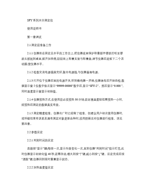
SFY系列水分测定仪使用说明书第一章调试2.1测定前准备工作2.1.1仪器放在固定且水平的工作台上,把仪器底面保护称重部件锣丝拧松至锣丝头部抵到桌面,掀开加热筒,轻轻放上称量支架与称量盘,调节仪器后底板下二个活动脚,使仪器水平。
2.1.2检查交流电源插座完好,取出电源线,与仪器接通电源。
2.1.3打开位于仪器后面的电源开关,听到蜂鸣器一声响,仪器通电后开始自检,数据显示窗5位数字依次显示“99999-00000”数字后,显示“SFY-2”。
然后显示“0.000 ”,同时温度显示窗显示初始值。
2.1.4仪器预热方式,在使用前必须预热30分钟,若环境温度较低需预热一小时,经预热后测定的数据真实有效。
2.1.5测定精度校准。
仪器出厂时已经做了校准。
但建议用户初次使用仪器时,或怀疑结果有误差及遇有测定对象是新品种时,须用烘箱法对仪器进行校准。
详见第四章。
2.2参数设定2.2.1判别时间的设定连续按“显示”键(每按一次,显示内容变化一次,直到仪器“判别时间”指示灯亮,此时仪器显示初始化值40秒,若需改动,增大则按“↑”键,减小则按“↓”键。
设定完成后按“清除”键,仪器回到现时重量显示状态。
2.2.2加热温度值设定需要调整加热温度值时,仪器右侧有一小门,在小门右上角向里轻按一下,小门自动弹开,(注意!小门右上角有一弹性开关锁住小门,不能直接向外用力开门,否则就会损坏小门开关结构按照打开小门背面上的调节指示图把中间的设定开关拨到设定位置,此时仪器面板上设定指示灯亮。
然后旋转设定旋钮,设定新的温度值(仪器出厂时,加热温度设定值为130℃。
再把开关拨回,此时正常指示灯亮。
当测定时,若实际温度值达不到控制温度值时,则缓慢旋转微调旋钮进行校准。
调整完后把小门轻按关上。
(温度控制有滞后,旋转微调旋钮后,应等待一点时间,观查显示值是否达到设定值,若没达到,再旋转微调旋钮,再等待,直到达到为止2.2.3连接打印机与计算机设定仪器通电开机后初始状态为可接打印机方式,此时可连接选配的打印机,每次测定完水分后,按“打印”键就可把水分值打印出来,仪器不在测试水分状态下,按“打印”键无效。
水力发电机使用说明书

水力发电机使用说明书1. 引言水力发电机是一种利用水能转换为电能的装置。
本使用说明书将详细介绍水力发电机的结构、工作原理、使用方法和注意事项,帮助用户正确操作和维护水力发电机,确保其安全有效运行。
2. 结构说明2.1 主体结构水力发电机主要由水轮机、发电机和控制系统组成。
水轮机将水能转化为机械能,传递给发电机,而发电机则将机械能转换为电能。
控制系统用于监测和调节水力发电机的运行状态。
2.2 水轮机水轮机通常由叶轮、转轴、导叶等组件构成。
叶轮的叶片采用特殊材料制成,以确保叶片在水流冲击下具有较高的强度和耐磨性。
转轴是水轮机的核心部件,承受着水轮机产生的转矩。
导叶可调节水流进入叶轮的角度,以达到最佳发电效果。
2.3 发电机发电机是将水轮机传递过来的机械能转换为电能的装置。
它由转子和定子组成,通过电磁感应原理实现电能的产生。
发电机还配备了冷却系统,以保持其在运行过程中的正常温度。
2.4 控制系统控制系统由监测设备、调节装置和保护机制组成。
监测设备用于实时监测水力发电机的运行情况,包括水轮机和发电机的温度、转速等参数。
调节装置可以根据需要调整水轮机和导叶的工作状态,以优化发电效率。
保护机制用于监控发电机的运行状态,一旦发现异常情况,将及时采取保护措施,以防止损坏。
3. 工作原理水力发电机利用水能转换为电能的基本原理是通过水流驱动水轮机转动,再由水轮机驱动发电机发电。
水力发电机的工作原理可简要描述如下:3.1 水流进入水轮机并击打叶轮。
3.2 受水流冲击,叶轮开始旋转。
3.3 旋转的叶轮带动转轴旋转。
3.4 转轴通过联轴器与发电机连接,传递旋转动力。
3.5 发电机根据转轴的动力产生电能。
4. 使用方法4.1 准备工作在使用水力发电机之前,必须确保供水源的稳定和充足。
同时,应对水力发电机进行必要的检查和维护,确保各部件的正常运行。
4.2 正常运行将水力发电机正确连接至水源,并根据实际需要调整水轮机和导叶的工作状态,使其能够达到最佳发电效果。
水力测功器操作规程

水力测功器操作规程本操作规程适用于D系列产品的水力测功器。
1、开机试验前的准备1.1开机前检查各运动部件应无卡阻,转动主轴应无异常响声,各润滑点应按使用说明书规定加注润滑剂;1.2检查联轴器与被试部件的联接,应做到安全可靠,并装好防护罩;1.3减震器内按要求加注:夏天68号机油,冬天32号机油。
油量以指针摆幅度最大时,使活塞不离开油面为宜;1.4往水箱内供水,保持恒压供水。
2、开机试验2.1启动电机带动测功器旋转,转动应正常可靠;2.2打开排水阀;2.3打开进水阀,改变进、排水阀的开度,调节测功器工作腔中的水环厚度,获得所需的制动力矩;2.4随时检查排水的温度,控制排水温度不大于70℃,若排水温度过高,则适当开大进水阀及开大排水阀,将排水温度降下来。
3、试验结束3.1关进水阀;3.2全开排水阀;3.3关机,停车;3.4放尽测功器里的积水;3.5停止往水箱供水,冬季时放尽水箱内余水防冻。
4、注意事项使用中为防止轴承进水,一般可按先开机,后放水;先关水,后停机的原则。
保证测功器在转动状态下进水,但又应防止测功器在无水状态下长期运转而烧坏密封件。
5、维护保养5.1安装和使用应有专人负责,负责人必须对测功器的结构和使用方法充分了解;5.2测功器到厂后必须作一次全面检查,每隔半年需对运动部件作一次全面的检查和保养;5.3联接被试部件和水力测功器时,注意不能和水力测功器主轴发生冲撞,以免影响水力测功器的精度;5.4在试验过程中,如发生强烈的震动,应立即停止,检查故障,以保证测功器运转正常;5.5测功器指针不能随意拨动,紧固螺母不应松动,以免影响指示值的正确性;5.6在低温季节应做好供水系统的防冻工作,工作完毕应放尽测功器内的积水;5.7个润滑点按规定时间、规定的润滑剂进行润滑;5.8搬运时将测功器的秤杆用绳子固定,防止摆动;5.9测功器使用半年后,要静校一次,或使用中发现静校精度达不到要求,必须重新进行校正,以达到系统精度;5.10定期检查、调整磁电测速传感器与测速齿轮见的间隙,保证间隙达到0.5-1.0㎜。
测功机使用说明书(中文)

CW系列电涡流测功机主机使用说明书凯迈(洛阳)机电有限公司(原洛阳南峰机电设备制造有限公司)目录1、引言 (4)1.1概述 (4)1.2电涡流测功机型号含义及技术参数 (4)2、涡流制动器的工作原理和主机结构 (6)2.1涡流制动器的工作原理 (6)2.2功率计算 (6)2.3主机结构 (6)2.4报警装置 (7)3、电涡流测功机主要技术指标 (7)4、涡流测功机的布置和安装 (8)4.1测功机的工作条件 (8)4.2测功机的布置 (8)4.3测功机的安装 ......................................................... .85、测功机的冷却 (11)5.1.冷却原理 (11)5.2对冷却水水质的要求 (11)5.3确定冷却水水量 (11)&电涡流测功机的润滑 (12)6.1油润滑 (12)6.2脂润滑 (12)6.3摆动轴承的润滑 (13)7、电涡流测功机校准和调节 (13)7.1静校 (13)7.2灵敏度检查 (18)8、电涡流测功机的运输和维护 (18)8.1测功机的贮存 (18)8.2测功机的运输 (18)8.3测功机的检查和维护 (19)9、配套 (20)10、..................................... CW盘式电涡流测功机的常见故障和排除方法2111、.......................................................... 润滑泵的使用和维护2212、图册部分 (24)图1(a)〜(b)电涡流测功机的主机结构 (25)图2(a)〜(o)电涡流测功机的机械特性曲线 (27)图3(a)〜(I)电涡流测功机的外形尺寸 (42)图4(a)〜(i)电涡流测功机的接线图 (54)图5水量、水温差及功率之间的关系 (63)1、引言1.1概述我公司根据德国策尔纳(Z?LLNER公司专有技术生产的CW系列电涡流测功机,具有低惯性、高精度、高稳定性和结构简单、维修方便、自成系列并适用于操作控制自动化等优点。
水力设备说明书

水力设备说明书1. 引言水力设备是一种利用水力能量进行动力传输和能量转换的机械设备。
本说明书将介绍水力设备的工作原理、使用方法、维护保养等方面的内容,以帮助用户正确使用并延长设备的使用寿命。
2. 设备概述水力设备包括水轮机、水泵、涡轮机、锅炉等,具体型号和规格可根据实际需求进行选择。
(此处可根据实际情况增加内容或调整表格排版)3. 工作原理水力设备利用水流或水压产生的动能来驱动机械运动或转化为其他形式的能量。
以下是水力设备常见的工作原理:(此处可根据实际情况增加内容或调整表格排版)4. 使用方法4.1 准备工作在正式使用水力设备之前,需要进行一系列准备工作,包括:(此处可根据实际情况增加内容或调整列表排版)4.2 启动和停止根据不同的水力设备,启动和停止的步骤有所不同。
一般情况下,应按照以下步骤进行操作:(此处可根据实际情况增加内容或调整列表排版)4.3 注意事项为确保安全使用水力设备,请注意以下事项:(此处可根据实际情况增加内容或调整列表排版)5. 维护保养5.1 清洁定期清洁水力设备的各个部件,并清除积聚的污垢。
注意使用适当的清洁剂,并避免清洗过程中造成损坏。
(此处可根据实际情况增加内容或调整列表排版)5.2 润滑定期对水力设备的润滑部件进行检查,并根据需要添加适量的润滑油,以确保设备正常运转。
(此处可根据实际情况增加内容或调整列表排版)6. 故障排除当水力设备出现故障时,应先排除常见的故障原因,如电源故障、连接不良等。
若无法自行解决,应及时联系专业维修人员进行维修。
(此处可根据实际情况增加内容或调整列表排版)7. 安全注意事项为确保操作人员的安全,请务必遵守以下注意事项:(此处可根据实际情况增加内容或调整列表排版)8. 结束语本说明书简要介绍了水力设备的工作原理、使用方法、维护保养等方面的内容,希望能够对用户正确使用设备起到一定的帮助作用。
如有任何问题,请随时与我们联系。
特别提示:本说明书仅供参考,请在使用水力设备前详细阅读设备相关说明书,并按要求进行操作。
西部水力工程吊车操作指南与配件手册说明书
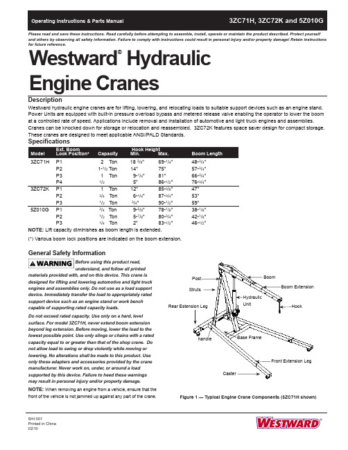
Westward HydraulicPlease read and save these instructions. Read carefully before attempting to assemble, install, operate or maintain the product described. Protect yourself and others by observing all safety information. Failure to comply with instructions could result in personal injury and/or property damage! Retain instructions for future reference.®General Safety InformationBefore using this product read, understand, and follow all printedmaterials provided with, and on this device. This crane is designed for lifting and lowering automotive and light truck engines and assemblies only. Do not use as a load support device. Immediately transfer the load to appropriately rated support device such as an engine stand or work bench capable of supporting rated capacity loads.Do not exceed rated capacity. Use only on a hard, level surface. For model 3ZC71H, never extend boom extension beyond leg extension. Before moving, lower the load to the lowest possible point. Use only slings or chains with a rated capacity equal to or greater than that of the shop crane. Do not allow load to swing or drop violently while moving or lowering. No alterations shall be made to this product. Use only those adapters and accessories provided by the crane manufacturer. Never work on, under, or around a load supported by this device. Failure to heed these warnings may result in personal injury and/or property damage.NOTE: When removing an engine from a vehicle, ensure that thefront of the vehicle is not jammed up against any part of the crane.SHI 001Printed in China BoomHydraulic UnitStrutsCasterFigure 1 — Typical Engine Crane Components (3ZC71H shown)AssemblyMODEL 3ZC71H (Refer to Figure 2)1. Attach swivel casters (No.12) to front extension legs (No.8) and rear extension legs (No.9) with washers and bolts (No.13).NOTE: Do not tighten any bolts unless told to do so.2. Place rear extension leg & frontextension legs inside base frame (No.1) with caster facing down and secure with bolt in frame, tighten bolts.3. Place post (No.4) on the base frame and secure with bolts (No.18).4. Put struts (No.10) on each side of post at top and secure with bolt and nut (No.14). Do not tighten. Place bottom of support on inside of base frame and secure with bolt and nut. (No.14).5. Attach base bracket (No. 20) to hydraulic unit (No.7) with bolts and nuts.6. Attach hydraulic unit assembly on post using bolt and nut (No.17).7. Place boom (No.5) on top of post and secure with bolt and nut (No.16). Pump ram using handle (No.19) until ram is approximately 2” above top. Place front mounting bracket on boom, on top of ram and secure with bolt and nut(No.15). Tighten all bolts in step 8 and step 9.8. Slide boom extension (No.6) inside of boom, making sure slot for chain & hook assembly (No.11) faces down and secure with bolt and nut (No.17) incorrect hole on boom for your particular job.9. Slide chain and hook through slot in lower front of boom extension and secure with bolt and nut (No.11).NOTE: Check all bolts and nuts fortightness, including those pre-assembled at the factory. Tighten where required.Westward Operating Instructions and Parts ManualWestward Hydraulic Engine Cranes®3ZC71H, 3ZC72K and 5Z010GFigure 2 — Assembly Parts Illustration for Models 3ZC71HIMPORTANT: Reference numbers are for assembly purposes only. See appropriate replacement partsillustration of your model for partsordering.141120171818Size of Hardware Kits11*- bolt & nut - M12X75 & M1213 - bolt & washer - M8X1614 - bolt & nut - M12X90 & M1215 - bolt & nut - M16X90 & M1616 - bolt & nut - M20X120 & M2017 - bolt & nut - M16X90 & M1618 - bolt - M12X2520*- bolt, washer & nut - M10X30 & M10* part of assemblyWestward Operating Instructions and Parts ManualModels 3ZC71H, 3ZC72K and 5Z010GMODEL 5Z010G (Refer to Figure 4)1. Attach swivel casters (No.13) to rear support (No.1) with bolts, nuts and washers (No.15).2. Attach wheel (No.17) to front legs (No.2 & 3) with bolts and nuts.NOTE: Do not tighten any bolts unless told to do so.3. Attach front legs (No.2 & 3) to rear support (No.1) with bolts and nuts (No.25).4. Place post support (No.26) on front legs and secure with bolts and washers (No.27).5. Place post (No.4) on post support(No.26) and secure with bolts and nuts (No.23).6. Put strut (No.7) on each side of post, secure the top with bolts and nuts(No.21), place angled portion of support on inside of each front leg and secure with bolt and nut (No.24).7. Attach boom (No.5) on post with bolt and nut (No.20).8. Attach base bracket (No.29) to hydraulic unit (No.9) with bolts andnuts. Place the hydraulic unit with base bracket to post, secure with bolt and nut (No.22) then pump the unit up until it reaches the boom and attach the upper part of unit to boom with bolt and nut (No.19).9. Slide boom extension (No.6) inside of boom (No.5), secure square washer (No.10) and bolt and lock washer(No.10), and secure the boomextension to boom in correct hole for particular job with lock pin and “R” pin (No.12).10. Attach hook (No.8) to boom extension(No.6) with bolt and nut.11. Tighten all bolts and nuts, the enginecrane is ready for use.IMPORTANT : Use boom in its retracted position whenever possible. Extend boom only when necessary to reach load. Be sure load is within capacity limit for boom position selected. If load is to be moved to another location, raise only high enough to clear floor, move crane slowly and avoid sudden stop that could cause load to swing (all models) violently.Westward Operating Instructions and Parts ManualWestward Hydraulic Engine Cranes®3ZC71H, 3ZC72K, and 5Z010GFigure 4 — Assembly Parts Illustration for Model 5Z010GIMPORTANT: Reference numbers are for assembly purposes only. See appropriate replacement parts illustration of your model for parts ordering.1234562189101212131517192020217222223242526272325299Size of Hardware Kits8* - bolt, washer & nut - M12X70 & M1210*- bolt - M8 X 1615 - bolt, washer & nut - M8X16 & M817*- bolt, washer & nut - M12X70 & M1219 - bolt, washer & nut - M12X85 & M1220 - bolt, washer & nut - M16X90 & M1621 - bolt, washer & nut - M12X70 & M1222 - bolt, washer & nut - M14X65 & M1423 - bolt, washer & nut - M10X60 & M1024 - bolt, washer & nut - M12X30 & M1225 - bolt, washer & nut - M12X70 & M1227 - bolt & washer - M12X2029* - bolt, washer & nut - M8X30 & M8* part of assemblyWestward Operating Instructions and Parts Manual OperationPuRGE AIR PRIOR TO OPERATION Sometimes during shipment and/or handling, air gets into hydraulic system causing poor lifting performance. T o correct this:1. Open release valve by turning it counterclockwise two full turns.2. Pump hydraulic unit about 6 full strokes.3. Close release valve and continue pumping until boom has raised several feet.4. Open release valve and slowly lower boom.NOTE: Avoid overtightening release valve - the tighter it is closed the harder it is to crack open for very slow lowering. OPERATING THE CRANENOTE: Capacity of crane varies with boom position. (See boom or Specifications chart.)1. Use boom in its retracted position, whenever possible.2. Extend boom only when necessary to reach load.3. Be sure load is within capacity limit for boom position selected.4. Close release valve (do not overtighten) and pump to raise load to desired height.IMPORTANT: If load is to be moved to another location, raise only high enough to clear floor. Move crane slowly and avoid sudden stops that could cause load to swing violently.CHANGING BOOM ExTENSIONDo not try to change boom position whileunder load. Do not exceed load capacity.NOTE: Check load rating located onboom or on Specifications chart.1. Place boom in horizontal position.2. Move boom and secure with pin and “R”clip.MaintenanceGENERAL1. Avoid overloads.2. Keep hook clean and inspectoccasionally for damage.3. Oil all moving joints periodically (at leastevery 30 days) with a medium weightmachine oil or motor oil.4. Keep sufficient hydraulic jack oil inreservoir.Do not use brake orshock absorberfluids. They have ingredients harmful to thejack’s oil seals.ADDING OIL1. Make sure boom is in lowered position.2. Remove oil fill plug from hydraulic unit.3. Squirt clean hydraulic jack oil into hole.NOTE: In most cases, the addition of afew ounces of oil is sufficient.4. Fill to level of filler hole. Do NotOverfill.RuST PREvENTION1. Check ram and plunger every 3 monthsfor rust or corrosion.2. Clean as needed and wipe with an oilycloth.NOTE: When not in use always positionboom and pump plunger all the way down.STORAGEWhen not in use, store the crane with thelegs folded and secured with the bolt pinsand “R” lock pins (Model 3ZC72K only).NOTE:If necessary to move the cranewith legs in the storage position, do sowith care and only across a smooth,level, seamless surface.See illustration below for details ofsecuring legs for storage.Models 3ZC71H, 3ZC72K and 5Z010G3ZC71H, 3ZC72K, and 5Z010G Westward Operating Instructions and Parts ManualWestward Hydraulic Engine CranesTroubleshooting ChartCrane will not lift load 1. Release valve not tightly closed 1. Ensure release valve tightly closed2. Overload condition 2. Remedy overload conditionCrane will lift, but not maintaining 1. Release valve not tightly closed 1. Ensure release valve tightly closed pressure 2. Overload condition 2. Remedy overload condition3. Hydraulic unit malfunctioning 3. ReplaceCrane will not lower after unloading 1. Reservoir overfilled 1. Drain fluid to proper level2. Linkages binding 2. Clean and lubricate moving parts Poor lift performance 1. Fluid level low 1. Ensure proper fluid level2. Air trapped in system 2. With ram fully retracted, remove oilfiller plug to let pressurized airescape, reinstall oil filler plugWill not lift to full height 1. Fluid level low 1. Ensure proper fluid level1 Hydraulic Unit BL80-60000-000 12 Oil Filler Plug 5905-00100-200 13 Pump Handle BL80-20000-000 14 Hydraulic Unit Bracket T473-00005-000 15 Boom Extension T473-00006-000 16 Braces T473-00001-000 27 Rear Leg Extension T473-40000-100 28 Frong Leg Extension T473-50000-100 29 Caster, 3-1/2" T473-04000-000 410 Hook Assembly T473-05000-000 1• Hardware Kit T473-06000-000 1 ** Seal Kit, Hydraulic Unit BL800S-034 1Please provide following information:-Model number-Serial number (if any)-Part descriptions and number as shown in parts list Address parts correspondence to:Grainger Parts P .O. Box 30741657 Shermer RoadNorthbrook, IL 60065-3074 U.S.A.1Hydraulic Unit BL80-50000-000 1 2Oil Filler Plug 5905-00100-100 1 3 Pump HandleBL80-20000-000 1 4 Hydraulic Unit Bracket T473-00005-000 1 5 Boom Extension T474-08000-000 1 6 BracesT474-00001-000 1 7 Front Wheel, 3-1/2" T474-00002-000 2 8 Middle Wheel. 3-1/2" T474-00002-000 2 9 Caster, 3-1/2" T474-04000-000 210 Hook Assembly T474-07000-000 1 11 Lock Pin T474-03000-000 2 • Hardware KitT474-50000-000 1**Seal Kit, Hydraulic Unit BL800S-034 1ReferencePart Number For Model: NumberDescription3ZC72K (1 Ton)Quantity.Repair Parts ListWestward Operating Instructions and Parts Manual3ZC71H, 3ZC72K and 5Z010G For Repair Parts, call 1-800-323-06201 Hydraulic Unit BL40-40000-000 12 Pump Handle BL80-20000-000 13 Hydraulic Unit Bracket T010-00005-000 14 Boom Extension T077-10000-000 15 Braces T077-00001-000 16 Front Wheel, 3-1/2" T474-90004-K18 27 Caster, T474-04000-000 28 Hook Assembly, Chain and Hook T375-50000-000 13ZC71H, 3ZC72K and 5Z010GWestward Operating Instructions and Parts ManualWestward Hydraulic Engine Cranes®11。
SL系列水力测功器使用说明书

使 用 说 明 书
四川诚邦测控技术有限公司
PDF 文件使用 "pdfFactory Pro" 试用版本创建
1
目录
SL 系列水力测功机使用说明书
一、 前 言 - - - - - - - - - - - - - - - - - - - - - - - - - - - - - - - - - - - - - - - - - - - - - - 3 二、技术规范----------------------------------4
SL 系列水力测功机是我公司生产的具有国际先进水平的水力测功 机。已广泛销售国内外,深受用户好评。
SL 系列水力测功机共有 8 个规格,均采用电动排水蝶阀控制,通 过改变蝶阀的开度来改变吸收功率的大小。其制动功率范围从 20kw 到 3300Kw,品种齐全,可供国内外用户选用。
该产品主要用来检测各种柴油机,汽油机,电动机等动力机的有效 功率,是动力机特性试验及传动机械的效率试验中不可缺少的测试设备。
传真:028 — 85140238
邮编:610041
PDF 文件使用 "pdfFactory Pro" 试用版本创建
6
SL 系列水力测功机使用说明书
4、特性曲线 水力测功机的应用范围,可以从它的特性曲线上看出,见图一(a),( b ),
( c ),( d ),( e ),( f ),( g ),( h )。特性曲线表示了测功机在不同转速下 所能吸收的功率范围。
760
840
1598.5×1310 1452×1558
×1135
×1310
1476×1200
1256×1559
×260
DY-6001 测功机控制器 使用说明书
DY-6001测功机控制器使用说明书蚌埠大洋传感系统工程有限公司目录一、主要功能及特点 (1)二、技术指标 (1)三、外壳尺寸与开孔尺寸 (1)四、外观介绍 (2)1.前面板 (2)2.前面板 (2)3.主显示界面 (3)4.参数设置界面 (3)5.PID整定界面 (3)五、仪表操作说明 (3)1.修改参数 (3)2.扭矩单位切换 (3)3.手动测试模式 (3)4.自动测试模式 (4)5.上位机测试模式 (4)6.复位模式 (4)7.PID参数整定 (4)六、参数说明 (4)1.扭矩通道 (4)2.扭矩量程 (4)3.扭矩系数 (4)4.扭矩小数点 (4)5.转速模式 (4)6.控制模式 (5)7.扭矩设定值0 (5)8.扭矩设定值1 (5)9.扭矩设定值2 (5)10.扭矩1测试时间 (5)11.扭矩2测试时间 (5)12.测试时间单位 (5)13.PID开始转速 (5)14.PID结束转速 (5)15.扭矩报警值 (5)16.转速报警值 (5)17.电流分度值 (5)18.转速小数点 (6)七、自动控制模式图 (6)八、参数表 (6)九、串口通信说明 (7)十、测功机接口说明 (7)十一、励磁输出接口说明 (8)十二、电机控制接口说明 (8)十三、电流输出说明 (8)十四、测功机扭矩校准说明 (9)十五、设备连接说明 (9)十六、装箱清单 (9)概述DY-6001测功机控制器是一种可以对多种扭矩传感器信号和测功机信号进行采样和处理,同时可控制磁粉磁滞制动器。
并将其信号传输至上位机。
其工作原理是将测功机传入的扭矩信号经过高精度ADC转换后,进行运算处理得到真实扭矩值。
再将转速传感器回传的信号经过处理得出实际转速值。
将两组数据进行运算后得出输出功率的大小,并将这三组数据送至显示器显示。
同时将当前数据传输至上位机进行曲线与表格绘制。
一、主要功能及特点●将当前测量的扭矩值与转速值实时显示。
●可以直接计算出当前功率值并显示。
Yamaha 10590, 10592, 10594 空气水力泵说明书
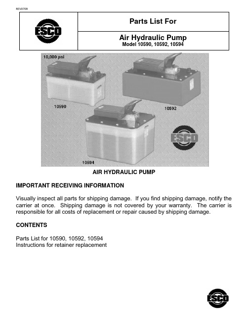
AIR HYDRAULIC PUMPIMPORTANT RECEIVING INFORMATIONVisually inspect all parts for shipping damage. If you find shipping damage, notify the carrier at once. Shipping damage is not covered by your warranty. The carrier is responsible for all costs of replacement or repair caused by shipping damage.CONTENTSParts List for 10590, 10592, 10594Instructions for retainer replacementItem No. Part No. No. Req'd DescriptionItem No. Part No. No. Req'dDescription1 41322 1 Foot Pedal 7 *305494 1 Decal (For 10592, 10594)2 *11032 2 Retaining Ring 8 302466 1 Spring Clip3 28386 1 Pin 9 260154 1 Trade Name Decal 4 211060 6 Screw (#9-15 X 1" Lg.; Torque to 25/35 in. lbs.; For 10590)10 2517621Warning Decal252168 10 Screw (Torque to 35/45in. lbs.; For 10594)PARTS INCLUDED BUT NOT SHOWN 5 *33853 1 Reservoir Gasket (For 10590)211060 4 Screw (#9-15 X 1" Lg.; Torque to 25/35 in. lbs.; For pump mounting purposes only; For 10590)*46271 1 Reservoir Gasket (For 10592)252168 4 Screw (1/4-10 X 1 Lg.; For pump mtg. purposes only; For 10594) *47409 1 Reservoir Gasket (For 10594)6 61243 1 Reservoir (Plastic; For 10590)Part numbers marked with an asterisk (*) are contained in a Repair Kit see sheet 5 of 6 for individual repair kit information.64153OR9 1Reservoir (For 10592)611651Reservoir (2 gal. plastic; For 10594)Note: These views may not be exact representations of your pump due to the variation of pumps listed, but all parts have been accounted for and are in this parts list.TOP & END VIEWSItemNo. Part No.No. Req'd DescriptionItem No. Part No. No.Req'd Description1 11151 4 Cap Screw (10-24 UNC X1-1/4 Lg.; Torque to 50/60 in. lbs.;10 *10273 1 O-ring (13/16 X 5/8 X 3/32; Nitrile) 2 37199 1 Intake Air Valve Body 11 64767 1 Pump Body3 *299921Foam Tube12174284Soc. Hd. Cap Screw (1/4-20UNC X 3-1/2 Lg.; Torque to 85/95 in. lbs. oiled.4 420965BK2 1 Cover Plate (For 10590)Note: Cross torque in increments of 30 in. lbs.)Relief Valve (When ordering a replacement relief valve refer to stamped number on the outside of the relief valve. See note below. Apply loctite 592 or equiv. & torque to 150/170 in. lbs.)58688BK2 1 Cover Plate (For10592)58706BK2 1 Cover Plate (For10594)5 11089 2 Washer (#10 bolt)6 11435 2 Soc. Hd. Cap Screw (10-24 UNC x7 58563 1 Release Valve Body NOTE: Standard relief valves are set at 10,100/10,700 PSI. Relief valves pre-set atspecial settings are available. Refer to your pump model number.8 11127 1 Pressure Plug (3/8 NPTF)92516891 Breather/Filler CapNote: These views may not be exact representations of your pump due to the variation of pumps listed, but all parts have been accounted for and are in this parts list.Refer to operating instructions Form No. 103544 for detailed information about operation, testing, disassembly, reassembly, and preventive maintenance.BASIC PUMP ASSEMBLYNote: These views may not be exact representations of your pump due to the variation of pumps listed, but all parts have been accounted for and are in this parts list.3442 38 37 364139,4030 44 51 46 45 43 5049 4847 124 35 78 9106 11,12 13 14SeeDetail1816,17 15 2019 2421 28; See Detail “B”27 262523 2233323130 29 35 34DETAIL “B”BASIC PUMP ASSEMBLY1 *28182 1 Air Valve Poppet 26 214586 1 Retaining Ring (Internal; For all reservoirsizes except 2 gal. Reservoirs built after June 1, 1998)2 *251717 1 O-ring (1" x 5/8 x 3/16) 27 *10263 1 Copper Washer (1" X .765 X 1/32) 3 28387 1 Muffler 28 *13934 1 U-cup & Backup4 *28239 1 Gasket 29 *304295 1 Retainer (Note:See "INSTRUCTIONS FOR RETAINER REPLACEMENT" sheet6 of 6) 5 52390 1 Piston Body 30 *17429 2 Backup Washer (2-15/16 X 2-3/4 X .045) 6 *14265 2 Piston Ring31 *13938 1 Compression Spring (1.452 O.D. X 4-7/16 Lg.) 7 *251835 2 O-ring (2-5/16 x 2-1/8 x 3/32) 32 28226 1 Piston 8 *10276 1 O-ring (1" X 3/4 X 1/8) 33 203143 1 Bumper9 *10272 1 O-ring (3/4 X 9/16 X 3/32) 34 210994 1 Spring Guide10 34378 1 Check Valve Body 35 37434 1 Air Cylinder (Note: Locate groove on upperhalf (top) of pump with chamfered tube end towards rear head as shown.)11 *250638 1 Filter Disc36 *12692 1 Compression Spring (3/16 O.D. X 1-11/16 Lg.)12 *11088 2 Retaining Ring (9/16 hole)37 *211052 1 O-ring (.900 X .706 X .097)13 *12522 2 O-ring (3/8 X 1/4 X 1/16; Urethane) 38 305475 1 Exhaust Valve Stem14 *11841 1 O-ring (1-5/8 x 1-3/8 x 1/8) 39 *10241 3 Lockwasher (For #10 bolt)15 *351021 1 Gasket40 211054 3 Screw (#10-24 X 1/2 Lg.; Torque to 50/55 in. lbs.)16 *10442 1 Washer (3/8 X 1/4 X 1/32) 41 33822 1 Piston End Plate 17 10002 1 Cap Screw (1/4-20 UNC X 3/8 Lg.; Torque to 90/110 in. lbs.)42 *28183 1 Piston Poppet18 *10445 1 Compression Spring 43 *205679 1 Compression Spring (.485 O.D. X .915 Lg.) 19 *10423 1 Steel Ball (9/32 Dia.; For 10590, 10592)44 *205674 1 Screw (8-32 UNC X 3/8 Lg.; Torque to 12/18 in. lbs.)*10423 2 Steel Ball (9/32 Dia.; For 10594) 45 51480 1 Rear Head20---------Relief Valve (When ordering a replacementrelief valve refer to stamped number on the outside of the relief valve. See note below. Apply loctite 592 or equiv. & torque to 150/170 in. lbs.)46 126911Compression Spring (3/8 O.D. X 1- 1/2 Lg.)21452781Piston Cylinder (Torque to 90/100 ft.lbs. oiled.)47 13936 1 Soc. Hd. Cap Screw (8-32 UNC X 1/4 Lg.) 22 *10375 1 Steel Ball (1/4 Dia.; For 10590, 10592) 48 281981 Seal Guide 23 *10261 1 Copper Washer (3/4 X 19/32 X 1/32)49 *216296 1 Filter Disc24 308893 1 Filter Adapter (Torque to 40/50 ft. lbs.oiled.; For 10590, 10592)See sheet 5 of 6 for pumps with 2 gal. reservoirs.)50 *10267 1 O-ring (7/16 X 5/16 X 1/16) 25 214578 1 Filter (For all reservoir sizes except 2 gal. reservoirs built after June 1, 1998)NOTE: Standard relief valves are set at 10,100/10,700 PSI. Relief valves pre-set at special settings are available. Refer to your pump model number.Part numbers marked with an asterisk (*) are contained in a Repair Kitsee sheet 5 of 6 for individual repair kit information.BASIC PUMP ASSEMBLY1 *28182 1 Air Valve Poppet 26 214586 1 Retaining Ring (Internal; For all reservoirsizes except 2 gal. Reservoirs built after June 1, 1998)2 *251717 1 O-ring (1" x 5/8 x 3/16) 27 *10263 1 Copper Washer (1" X .765 X 1/32) 3 28387 1 Muffler 28 *13934 1 U-cup & Backup4 *28239 1 Gasket 29 *304295 1 Retainer (Note:See "INSTRUCTIONS FOR RETAINER REPLACEMENT" sheet6 of 6) 5 52390 1 Piston Body 30 *17429 2 Backup Washer (2-15/16 X 2-3/4 X .045) 6 *14265 2 Piston Ring31 *13938 1 Compression Spring (1.452 O.D. X 4-7/16 Lg.) 7 *251835 2 O-ring (2-5/16 x 2-1/8 x 3/32) 32 28226 1 Piston 8 *10276 1 O-ring (1" X 3/4 X 1/8) 33 203143 1 Bumper9 *10272 1 O-ring (3/4 X 9/16 X 3/32) 34 210994 1 Spring Guide10 34378 1 Check Valve Body 35 37434 1 Air Cylinder (Note: Locate groove on upperhalf (top) of pump with chamfered tube end towards rear head as shown.)11 *250638 1 Filter Disc36 *12692 1 Compression Spring (3/16 O.D. X 1-11/16 Lg.)12 *11088 2 Retaining Ring (9/16 hole)37 *211052 1 O-ring (.900 X .706 X .097)13 *12522 2 O-ring (3/8 X 1/4 X 1/16; Urethane) 38 305475 1 Exhaust Valve Stem14 *11841 1 O-ring (1-5/8 x 1-3/8 x 1/8) 39 *10241 3 Lockwasher (For #10 bolt)15 *351021 1 Gasket40 211054 3 Screw (#10-24 X 1/2 Lg.; Torque to 50/55 in. lbs.)16 *10442 1 Washer (3/8 X 1/4 X 1/32) 41 33822 1 Piston End Plate 17 10002 1 Cap Screw (1/4-20 UNC X 3/8 Lg.; Torque to 90/110 in. lbs.)42 *28183 1 Piston Poppet18 *10445 1 Compression Spring 43 *205679 1 Compression Spring (.485 O.D. X .915 Lg.) 19 *10423 1 Steel Ball (9/32 Dia.; For 10590, 10592)44 *205674 1 Screw (8-32 UNC X 3/8 Lg.; Torque to 12/18 in. lbs.)*10423 2 Steel Ball (9/32 Dia.; For 10594) 45 51480 1 Rear Head20---------Relief Valve (When ordering a replacementrelief valve refer to stamped number on the outside of the relief valve. See note below. Apply loctite 592 or equiv. & torque to 150/170 in. lbs.)46 126911Compression Spring (3/8 O.D. X 1- 1/2 Lg.)21452781Piston Cylinder (Torque to 90/100 ft.lbs. oiled.)47 13936 1 Soc. Hd. Cap Screw (8-32 UNC X 1/4 Lg.) 22 *10375 1 Steel Ball (1/4 Dia.; For 10590, 10592) 48 281981 Seal Guide 23 *10261 1 Copper Washer (3/4 X 19/32 X 1/32)49 *216296 1 Filter Disc24 308893 1 Filter Adapter (Torque to 40/50 ft. lbs.oiled.; For 10590, 10592)See sheet 5 of 6 for pumps with 2 gal. reservoirs.)50 *10267 1 O-ring (7/16 X 5/16 X 1/16) 25 214578 1 Filter (For all reservoir sizes except 2 gal. reservoirs built after June 1, 1998)NOTE: Standard relief valves are set at 10,100/10,700 PSI. Relief valves pre-set at special settings are available. Refer to your pump model number.Part numbers marked with an asterisk (*) are contained in a Repair Kitsee sheet 5 of 6 for individual repair kit information.BASIC PUMP ASSEMBLYPart numbers marked with an asterisk (*) are contained in a Repair Kit see below for individual repair kit numbers .FILTER ADAPTER ASSEMBLY AFTER 6/1/98For 2 Gallon Reservoirs Only (Reference Part Number 48007)Item No. Part No. No. Req’d Description 1 422016 1 Adapter Filter 2 29682 1 FilterItem No. Part No. No. Req'dDescription1 *206504 1 Foam Tube2 28227 1 Release Valve Button3 *10266 1 O-ring (3/8 X 1/4 X 1/16)4 *13944 1 Compression Spring (3/8 O.D. X 1/2 Lg.)5 34377 1 Poppet Retainer6 *15279 1 O-ring (1/2 X 3/8 X 1/16)7 13937 1 Dowel Pin (Note: Place tapered end toward ball.)8 29037 1 Release Valve Poppet 9 *14443 1 Steel Ball (3/32 Dia.) 10 209736 1 Ball Retainer11*139591Compression Spring (1/8 O.D. x 1/2 Lg.)REPAIR KITS No. 300805 No. 300831 10590 No. 300848 10592 10594Seat atAss’y4 3 2 1 7 65 9 8 1110 12INSTRUCTIONS FOR RETAINER REPLACEMENTYour pump’s retainer is locked into place by one of the following methods. Determined which method was used on your pump’s retainer. Then followed the appropriate steps to remove the old and install and stake the new.Method 1 – Retainer shows no sin of stake marks1. This retainer has been locked in place with a Locite product. To replace it, a moderate amount ofheat needs to be applied to the cylinder nut (in the area of the retainer) to soften the existing Locite allowing it to be removed.2. Install the new retainer into the cylinder nut and torque to 80/100 in. lbs. Note: Do not use a Lociteproduct this time but stake the new retainer in place according to instructions in Step 3.3. To lock retainer into place, use a center punch positioned in the seam between the retainer and thecylinder nut and stake the new retainer in two places approximately 180° apart.Method 2 – Retainer has two stake marks in the seam between the retainer and the cylinder nut.1. For replacement of this retainer, the stake marks must be removes. Using 1/8” or larger diameter drillbit, remove the exiting stakes by drilling a short distance into the stale marks. Remove the retainer.2. Install the new retainer into the cylinder nut and torque to 80/100 lbs.3. To lock retainer into place, use a center punch positioned in the seam between the retainer and thecylinder nut and stake the new retainer in two places approximately 180° apart.NOTE: Do not stake in the old stake marks.Cylinder nut RetainerThread seam。
SHEW Series水力泵数据手册说明书
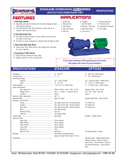
Horsepower................................................................................................15 – 200 HP 15 – 2000 HP ( SHEW Series ) Discharge Size............................................................................................3” – 8”3” – 20” ( SHEW Series ) Performance RangeCapacity................................................................................100 – 4,500 US GPM 100 – 20,000 US GPM ( SHEW Series )Head ......................................................................................10’ – 160’ TH50’ – 350’ TH ( SHEW Series )Solids Handling..........................................................................................1-3/8” to 2-1/2” Particle Size 1” – 5” Particle Size ( SHEW Series )Motor NomenclatureType, Speed, HZ ..................................................................TEFC Air Filled / 1180 to 1780 / 60 HZ Explosion Proof / 890 / 50 HZ Voltage, Phase......................................................................480 V. / 3 Phase / 1.5 Service Factor 240 / 575 / 2400 / 4160 Volt Insulation ..............................................................................Class F Class HMaximum Water Temperature................................................................180°F. +Operation Mode ........................................................................................Manual or SnoreVariable Speed Drive / Float Controls Materials of Construction........................................................................Casing....................................................................................28% High Chrome 650+ Brinell Hardness 15/3 White Iron Impeller..................................................................................28% High Chrome 650+ Brinell Hardness 15/3 White Iron Wear Plate............................................................................28% High Chrome 650+ Brinell Hardness 15/3 White IronShaft ......................................................................................416 Stainless Steel Bearing Housing..................................................................Cast IronFasteners ..............................................................................316 Stainless Steel Impeller Type..............................................................................................Semi-OpenEnclosed ( SHEW Series )Mechanical SealUpper Seat............................................................................Silicon Carbide Upper Rotator ......................................................................Silicon Carbide Lower Rotator......................................................................Silicon Carbide Lower Seat............................................................................Silicon Carbide Elastomers............................................................................Viton Labyrinth Seal......................................................................Cast Steel316 Stainless Steel / BronzeBearings......................................................................................................Permanently Lubricated DoubleAngular Contact 100,000 Hour B-10 LifeAccessories ................................................................................................Discharge Hose / Variable Speed Drives / Urethane Coating / Elbows in Steel or High Chrome / Control Panels / Moisture and Thermal Protection / Float Controls / RaftsFEATURESAPPLICATIONS1. Bottom Ash2. Tailings Ponds3. Sand Gravel4. Clean Out Sumps5. Coke Pits6. Dredging7. Coal Pile Runoff 8. Slag Pits / Mill Scale 9. Boiler Blow Down 10. Lime Slurry11. Red Mud Recovery 12. Thickener Drain13. Precipitation Thickener 14. API SludgeSPECIFICATIONSHEAVY DUTY HIGH CHROME SLURRY PUMPSPECIFICATIONSSTANDARDOPTIONSFactory–4432VentureAvenue•Duluth,MN55811•218.722.9904•Fax218.722.2826••email:***************©GPM,INC.20021. Semi-Open ImpellerAdjustable wear plate increases wear life when pumpage contains heavy abrasive particles.28% High Chrome 650+ Brinell hardness: assures long life of Impeller, Wear Plate and Casing.2. Slurry Mechanical SealDual Seals of Silicon Carbide vs. Silicon Carbide running with out the need for flush water.The motor is further protected by a labyrinth seal and upper lip seals.3. Heavy Duty Wash-down MotorInverter duty TEFC, Severe service, low voltage motor minimizes the cost of operation.4. No packing or Shaft SleevesSpray holes are standard on every pump Agitator’s optional for thick, heavy slurries.If you have problems with packing and seal water,this pump will solve all your problems.STANDARD HORIZONTAL SHLH SERIES。
CJYH09冲击式水轮机说明书
CJYH09-L-170/6×15型冲击式水轮机系立轴单转轮六喷嘴冲击式水轮机,与发电机组成两支点水轮发电机组。
该水轮机由喷嘴装配、转动部份、预埋部份、管路部份、机盖装配、油轴承、工具等部份组成。
水轮机转轮与发电机主轴采用法兰连接,摩擦力传递扭矩。
水轮机转轮系整体铸造而成,最大外径为φ2190.1mm,拆卸转轮采用下拆方式。
该型立轴六喷嘴水轮机的喷嘴采用的是全新单元组合式结构,喷嘴、偏流器组成一体,以进水管定位装在进水管的喷嘴座上。
为便于转轮和喷嘴的装拆与检修,在机座的下方设有平水栅,平水栅同时也起到均衡排水作用,减少对尾水渠的冲刷。
在平水栅中间铺有两根轻型钢轨,运输小车将转轮或喷嘴,沿此轨道经运输通道运出或运入机坑。
由直流式内控喷嘴和偏流器组成的双重调整机构,调节性能良好,能满足电能质量和调节保证的要求,确保机组和压力钢管的安全。
每台水轮机的进水管前装有一个直径为φ1600mm的进水阀装置。
喷针及偏流器接力器均采用单腔油压控制,操作油压6.3MPa,压力油取自调速器。
机组和冲击式专用调速器、自动化元件组成一个完整的自动化操作系统,中控室一个脉冲,机组能自动启动带负荷、自动停止、正常运行、事故报警和停机。
机组采用的内拆式水力自关闭喷嘴具有以下特点:1)喷针利用油压开启,水力自关闭,当电站的操作油失压时,喷针能在水力作用下自动关闭。
喷嘴关闭后,如果关闭压力油进油阀,切断油压装置的压力油源,喷针也不会自行开启,非常安全。
2)喷嘴具有负荷自锁功能,当机组并网运行时,例如油压装置出现事故低压等,能自动锁定喷针,二次回路的低油压事故停机信号应作用于调速器数字配压阀,封闭喷针控制腔油路,使机组继续带原有负荷在电网中运行,直到油压装置故障消除。
因此,可减少事故停机次数。
3)可单独开启喷针,排除卡塞喷针的异物。
4)设有新型油水隔离装置,保证压力水不会渗入喷针控制腔,不会造成油水混合。
5)设有防泥砂装置,能防止泥砂进入喷针轴,保护零件不受泥砂磨损。
YP系列水力测功器说明书
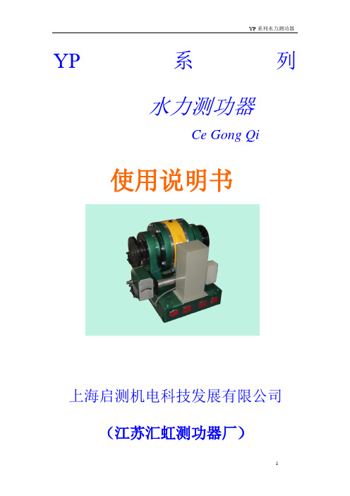
YP系列水力测功器Ce Gong Qi使用说明书上海启测机电科技发展有限公司(江苏汇虹测功器厂)一、前言YP系列(压力式)水力测功器, 国外在60、70年代已广泛使用。
我们在85年通过许可证贸易, 引进了西德策尔纳(zoller)公司技术, 开发生产该型号的先进测功器。
我们通过消化、吸收国外技术,进行全新优化设计、生产,可提供全系列产品。
YP系列水力测功器共有12个规格,均采用电动排水蝶阀控制。
即通过改变蝶阀的开度来改变吸收功率的大小。
制动功率范围从20KW到5900KW,品种齐全,国内外用户根据自己发动机功率范围选择合适的机型选购。
该产品主要用来检测各种柴油机、汽油机、电动机等动力机的有效功率。
是动力机特性试验、传动机械的效率试验中不可缺少的测试设备。
该产品基本型为单方向测试,用户如需同时双向试验订货时请提出要求后,我公司给予专门定制。
二、技术规范1.主要特点◆体积小,安装容易;◆结构简单,操作维护方便;◆制动力矩大;◆测量精度高;◆工作稳定可靠;◆磁电式测速传感器实现高精度瞬时转速测量;◆电控蝶阀快速负载控制;◆响应速度快,适于动态试验。
2.测量性能指标3.技术参数本表单位:mm4.特性曲线水力测功器的应用范围,可以从它的特性曲线上看出,见图一(a)、(b)、(c)、(d)、(e)、(f)、(g)、(h)。
特性曲线表示了测功器在不同转速下所能吸收的功率范围。
OA曲线表示测功器在一定进水压力下,随着转速的变化所能吸收的最大功率线。
AB直线为保持测功器扭矩为最大值时,随着转速的变化,测功器所能吸收的最大功率线。
AC直线(YP20型)与BC直线为不超过测功器最大容许的排水温度时,测功器所能吸收的最大功率限制线。
CD直线为测功器最高转速限制线。
OD曲线为测功器不充水时的制动功率线(空气磨擦阻力)。
曲线图形OABCDO所包围的区域表示了该型水力测功器所能吸收的功率范围。
这也是动力机性能试验时选用测功器的依据。
北方工具与设备有限公司水力管道筒装置所有者手册说明书
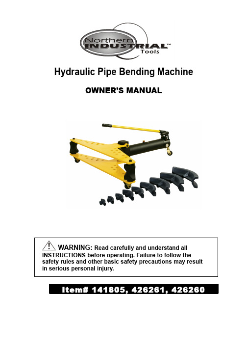
Hydraulic Pipe Bending MachineOWNER’S MANUALINSTRUCTIONS before operating. Failure to follow the safety rules and other basic safety precautions may result in serious personal injury.Thank you very much for choosing a NORTHERN TOOL + EQUIPMENT CO., INC. Product! For future reference, please complete the owner’s record below:Model: _______________ Purchase Date: _______________Save the receipt, warranty and these instructions. It is important that you read the entire manual to become familiar with this product before you begin using it.This machine is designed for certain applications only. Northern Tool + Equipment cannot be responsible for issues arising from modification. We strongly recommend this machine is not modified and/or used for any application other than that for which it was designed. If you have any questions relative to a particular application, DO NOT use the machine until you have first contacted Northern Tool + Equipment to determine if it can or should be performed on the product.For technical questions please call 1-800-222-5381.Intended Use:The Hydraulic Pipe Bender is designed for bending thick-walled pipes (black iron, schedule 40 &80, etc.). There are six different bending dies ranging from 1/2" to 2" for Item# 141805, eight different bending dies ranging from 1/2" to 3" for Item# 426261 and nine different bending dies ranging from 1/2" to 4" for Item# 426260. The Hydraulic Pipe Bender is not designed for bending thin-walled pipesTECHNICAL SPECIFICATIONSModel (Item#) SF-2 (141805) SF-3(426261) SF-4(426260)Item UnitBending Dies Inch 2 3 4Max. workingpressurePSI 6260 8000 8500Max. off-loadpressurePSI 6686-7258 8000 8500 Max. working load Lbs. 18000 42000 44000Max. working stroke Inch 9 27/32 16 1/2 16 1/2O.D MM Ø21.5~60 Ø21.5~88.5 Ø21.5~108 CapacityThickness MM 2.75~4.5 2.75~4.5 2.75~4.5 Oil tank capacity Quarts 1 1/4 1 7/8 3 1/8Bending angle Degree 90°~180°90°~180°90°~180°Oil grade # N15 N15 N15Max. operating force Lbs. ≤110 ≤110≤110SF-2 (141805) SF-3(426261) SF-4(426260)Pipe Size Schedule40Schedule80Schedule40Schedule80Schedule40Schedule801/2" YES YES YES YES YES YES 3/4 " YES YES YES YES YES YES 1 " YES YES YES YES YES YES 1-1/4 " YES NO YES NO YES NO 1-1/2 " YES NO YES NO YES NO 2" YES NO YES NO YES NO 2-1/2" N/A N/A YES NO YES NO 3" N/A N/A YES NO YES NO 4" N/A N/A N/A N/A YES NOGENERAL SAFETY RULESWARNING: Read and understand all instructions. Failure to follow all instructions listed below may result in electric shock, fire and/or serious injury.WARNING:The warnings, cautions, and instructions discussed in this instruction manual cannot cover all possible conditions or situations that could occur. It must be understood by the operator that common sense and caution are factors which cannot be built into this product, but must be supplied by the operator.AssemblyNo special set up is required and little space is needed to operate the bending machine.1- Assembly of the lower plate: First turn over the cylinder and remove the four hex bolts on the base of the cylinder. Align the four holes of the lower plate with the holes of the cylinder base, and affix with the hex bolts taken from the cylinder base.2- Assembly of the upper plate: When the lower plate is assembled, turn the cylinder over and insert two swaging blocks in the hole of the lower plate. Place the upper plate over the swaging blocks and use the die cover shaft (Part# 55) to secure the swaging block and the back oil cylinder seat (Part# 58).OPERATIONBefore using, check the hydraulic oil in the cylinder by loosing the vented oil bolt (Figure 1) and visually ensure that the piston inside is covered in oil when the pipe bender is in the horizontal position.Figure 1: Vented oil boltSTEPS1. Tighten release valve (Part# 26) by turning clockwise.2. Loosen vented oil bolt (Part# 46).3. Grease die cover (Part# 56), swaging blocks (Part# 68) and the tube to be bent.4. Lift the upper plate (Part# 64) and affix bending die to the end of the cylinder ram as shown inFigure 2. Place two swaging blocks into the holes of lower plate (Part# 54) and place tube in front of them. Turn the swaging blocks so their grooves face toward the tube die (Figure 3).5. To account for the pipe shortening during the bending process, make sure the pipe extendsbeyond the swaging blocks, as shown in Figure 3.Figure 2: Die installed on cylinder ram.Figure 3: Pipe is installed beyond swaging blocks to account for pipe shortening during the bend.NOTE: For short pipes, set the swaging blocks closer together, as shown in Figure 4, to ensure that the pipe extends beyond the swaging blocks to account for pipe shortening during the bend.Figure 4: Swaging blocks set close together for bending short pipes.6. Return upper plate to original position and use the advance pump (See Figure 5) to quicklyadvance the die. Note:Only one handle is included with the bending machine. The picture below shows a piece of pipe being used as a handle in the advance pump.Figure 5: Operating pumps and release valve7. Use the forming pump to apply heavy pressure to bend the pipe to its desired angle.8. When finished bending, release the pressure by opening the release valve. The ram willautomatically retreat. Lift the upper plate to take out the bent tube.IMPORTANT:•Before use, check the oil in oil tank to make sure there is enough oil to operate pipe bender. •Loosen vented oil bolt to ventilate.•Before bending any pipe, the release valve must be closed.•The outside diameter of pipe must fit the groove of tube die, or else the pipe will be shaken or the tube die will burst.•The contact surface between tube and the two swaging blocks must be smooth. Coat swaging blocks with lubricating oil. Make sure a weld seam is not at the bending point.•If air is in the pump, firstly loose the vented oil bolt. Raise the cylinder head to make the pipe bending machine tilt at 45° position. Then, pressing down the handle until there is no air in the cylinder. When the air emitted, loosen the release valve counterclockwise to make the cylinder ram go back and then place the pipe bending machine horizontally.•Strictly observe the technical parameters while using the pipe bender. Excessive pressure is unadvisable since it will damage the machine.•Periodically clean and maintain the machine. Use clean, filtered oil, making sure the filter (Part#30) is cleaned regularly.•Lock the vented oil bolt when finished using the machine.Maintenance•It is basically maintenance free. However, the oil level should be kept constant at about 1 ¼Qts.(141805), 1 7/8Qts.(426261), 3 1/8Qts.(426260) of quality hydraulic oil.•Too much oil will force the surplus oil to leak from the cylinder seals and possible damage them.•Not enough oil will cause loss of power as air will be sucked in, causing a drop in pressure.Figure 6: Vented oil bolt removed from cylinderTroubleshooting1. The cylinder ram is extended feebly.•Check the steel ball in release valve (Part# 26) to see if it has fallen. Then tighten release valve clockwise.•Check the hydraulic oil to make sure the cylinder (Part# 45) is filled.•Check the vented oil bolt (Part# 46) to see if it is loose.•Change the polyurethane seal ring (Part# 36) in plunger pump.•Remove the air in cylinder.2. There is air in the plunger pump or there is no oil in the plunger pump.•Remove the air in cylinder.•There isn’t enough oil in the oil tank; add oil•Oil grade isn’t according to standards, change with quality hydraulic oil.•There is dirt in the filter, and it must be cleaned. Dismantle filter with wrench and clean copper mesh.Diagram and Parts ListPARTS LISTITEM DESCRIPTION ITEM DESCRIPTION1 PUMP HANDLE GRIP 41 PISTON-ROD2 PUMP HANDLE 42 COPPER WASHER3 FORMING PUMP SUPPORT 43 OIL SEAL GASKET 19*14*24 ADVANCE PUMP SUPPORT 44 CAP SCREW M14-2*455 SOLID PIN 6*35 45 OIL CYLINDER6 ROLL PIN 1.5*16 46 VENTED OIL BOLT7 CONNECTING ROD 47 OIL SEAL GASKET 21*14*28 LARGE PLUNGER ROD 48 OIL TANK9 YX SHAPE SEAL RING D28 49 RUBBER SEAL PD60*80*1010 LARGE PLUNGER CASE 50 O-RING 95*3.111 OIL SEAL GASKET 48*39*3 51 O-RING 1612 SMALL PLUNGER ROD 52 PIN SHAFT13 YV SHAPE SEAR RING D16 53 ROLL PIN 3*3014 SMALL PLUNGER CASE 54 LOWER PLATE15 OIL SEAL GASEKT 31*24*3 55 DIE COVER SHAFT16 FOOTSTEP 56 DIE COVER17 HEX BOLT M8-1.25*20 57 O-RING 2018 FLAT WASHER 8 MM 58 BACK OIL CYLINDER SEAT19 PIN SHAFT A6*28 59 OIL CYLINDER SPLICING CAP20 ROLL PIN 1.5*16 60 GUIDE SLEEVE21 HEX NUT M12-1.75 61 CAP SCREW M5-0.8*3022 UNIVERSAL WHEEL 62 HEX BOLT M14-2*2523 STEEL PEARL 6.5MM 63 SPLIT PIN 1424 PLUG SCREW M8-1.25*10 64 UPPER PLATE25 FLAT HD SCR M4-0.7*12 65 SWAGING BLOCK BRACKET26 RELEASE VALVE 66 PIN SHAFT A10*4527 NEEDLE VALVE CORE 67 ROLL PIN 2.5*2028 CHAMPING RING 68 SWAGING BLOCK29 ROLL PIN 4*10 69 HEX NUT M6-130 OIL FILTER 70 FLAT HD SCR M6-1*1631 PHLP HD SCR M4-0.7*10 71A 1/2" BENDING DIE32 COMPRESSION SPRING 71B 3/4" BENDING DIE33 FRONT OIL CYLINDER SEAT 71C 1" BENDING DIE34 O-RING 95*3.1 71D 1-1/4" BENDING DIE35 O-RING 58*4 71E 1-1/2" BENDING DIE36 YX SHAPE SEAL RING D50 71F 2" BENDING DIE37 FRONT SPRING SEAT 72A 2-1/2" BENDING DIE38 CAP SCREW M8-1.25*30 72B 3" BENDING DIE39 TENSION SPRING 73A 4" BENDING DIE40 BACK SPRING SEATFor replacement parts and technical questions, please call 1-800-222-5381MANUFACTURER’S LIMITED WARRANTYThe limited warranty set forth below is given by Northern Tool + Equipment Company Inc., (NTE) with respect to new merchandise purchased and used in the United States, its possessions and territories.NTE warrants this product against defects in material and workmanship for a period of 12 months parts/ 12 months labor, commencing on the date of original purchase and will, at its option, repair or replace, free of charge, any part found to be defective in material or workmanship. This limited warranty shall only apply if this product has been operated and maintained in accordance with the Owner’s Manual furnished with the product, and has not been subject to misuse, abuse, commercial use, neglect, accident, improper maintenance, alteration, vandalism, theft, fire, water or damage because of other peril or natural disaster. Damage resulting from the installation or use of any accessory or attachment not approved by NTE for use with the products(s) covered by this manual will void your warranty as to any resulting damage. This warranty is limited to ninety (90) days from the date of original retail purchase for any NTE product that is used for rental or commercial purposes, or any other income-producing purposes.This limited warranty does not provide coverage in the following cases:1. User does not comply with the instructions and exceeds the claimed capacity.NTE reserves the right to change or improve the design of any NTE product without assuming any obligation to modify any product previously manufactured.No implied warranty, including any implied warranty of merchantability or fitness for a particular purpose, applies after the applicable period of express written warranty above as to the parts as identified. No other express warranty or guaranty, whether written or oral, except as mentioned above, given by any person or entity, including a dealer or retailer, with respect to any product shall bind NTE during the period of the Warranty, the exclusive remedy is repair or replacement of the product as set forth above. (Some states do not allow limitations on how long an implied warranty lasts, so the above limitation may not apply to you.)The provisions as set forth in this warranty provide the sole and exclusive remedy arising from the sales. NTE shall not be liable for incidental or consequential loss or damages including, without limitation, expenses incurred for substitute or related expenses, or for rental expenses to temporarily replace a warranted product. (Some states do not allow limitations on how long an implied warranty lasts, so the above limitation may not apply to you.)In no event shall recovery of any kind be greater than the amount of the purchase price of the product sold. Alteration of the safety features of the product shall void this warranty. You assume the risk and liability for loss, damage, or injury to you and your property and/or to others and their property arising out of the use or misuse or inability to use the product.This limited warranty shall not extend to anyone other than the original purchaser, original lessee or the person for whom it was purchased as a gift.How State Law Relates to this Warranty: This warranty gives you specific legal rights, and you may also have other rights which vary from state to state.For questions about your warranty, please call 1-800-222-5381.Northern Tool + Equipment Co.,2800 Southcross Drive WestP.O. Box 1499 Burnsville, MN 55337-0499Made in China。
Denison GOLD CUP 水力泵和动力机说明书
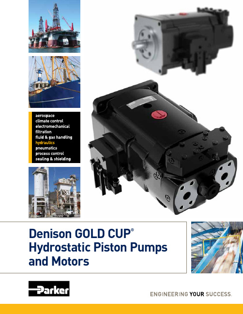
GOLD CUP® Benefits
Increase productivity and save power
• High speed operation • Auto-regulated control
Reduce Down Time
The uniquely designed GOLD CUP pump valve block contains multiple poppet valves to provide relief and control pressure functions along with a built-in compensator. Standardized to ensure complete interchangeability among all GOLD CUP pump sizes, a simple exchange to replace a malfunctioning valve block alleviates down time and ensures greater productivity.
GOLD CUP – 38,900 HOURS
TYPICAL HYDROSTATIC PUMP – 22,700 HOURS
70% *
Longer life
0 hrs
5000
10000
15000
20000
25000
30000
35000
40000
CONDITIONS = 3500 psi, 46 cSt, 1800 RPM
The hydrostatically balanced cam and cradle design promote efficient stroking and pump longevity.
- 1、下载文档前请自行甄别文档内容的完整性,平台不提供额外的编辑、内容补充、找答案等附加服务。
- 2、"仅部分预览"的文档,不可在线预览部分如存在完整性等问题,可反馈申请退款(可完整预览的文档不适用该条件!)。
- 3、如文档侵犯您的权益,请联系客服反馈,我们会尽快为您处理(人工客服工作时间:9:00-18:30)。
Y SeriesHydraulic dynamometerManualShanghai LINYAOPower Test Equipment Co., Ltd.2011-10ForewordY series hydraulic dynamometers are used electric drain valve control. That is, by changing the valve opening to change the size of the absorbed power. Braking power range from 20KW to 5900KW, full range of domestic and foreign users according to their range of engine power to choose the right model to buy.The product is mainly used to detect a variety of diesel, gasoline, motor and other power machine of effective power. Is a power machine characteristics test, test the efficiency of transmission machinery essential test equipment. The basic product is a one-way test, user test for both two-way ordering, please request, our company has given special customization.Technical Specifications1. Features◆Small size, easy to install;◆Simple structure, convenient operation and maintenance;◆braking torque;◆high accuracy;◆stable and reliable;◆magnetic-electric speed sensor for high accuracy measurement of the instantaneous speed;◆electric control valve fast load control;Performance MeasurementProject types range sensor accuracy RemarksSpeed ZSB magnetoelectric speed sensor 300-7500r/min ± 1r/min than 7500r/minWhen the wheel speed and control of the separate componentsoutside the grounds.Torque strain gauge pressure sensor and pull the dynamometer scale matching ± 0.2% FSPrecision potentiometer valve position(DPF, YZ60 water gate actuator) 0-100% 0.2% F.SPrecision potentiometer throttle position(YZ60, YZ60A throttle actuator) 0-100% 0.2% F.S3.Technical parametersThe Unit:mmDynamometer structureY-type hydraulic dynamometer mainly by body parts, body parts measured force, into the drainage components, calibration components, electric drain valve parts, auto-adjusting device composed of parts and lubricating parts. See Figure II (a), (b).1. Body partsBody parts is to use the dynamometer to absorb water, the main components of the effective torque power machine. Figure three (a), (b).Power machine output mechanical energy into heat in here, by the absorption of water into the shell in the discharge away, a very small part by the dynamometer casing wall heat to the air.Its simple structure from the one in the rolling bearing can swing on a rack in the shell and composed of the rotor on the spindle. Dynamometer rotor mounted on the spindle center, left and right side of the bearing shell and the shell were symmetrical around the rotor mounted on both sides, left and right side of the rotor shell pits and pit forming the working chamber. Shell around the bearing housing connected with bi-metal sleeve bushing play a role in both, also played a role in sealing water. Y1500, Y2500, Y3300, Y5900-type dynamometer in order to prevent water leakage from the gap sealed to prevent water from entering the bearing to ensure that the bearing life.Shell has opened a drainage hole, so the bearing shell has opened a water hole, in order to ensure the entry of cold water and hot water discharge. Around the bearing housing has a overflow pipes, dump the water cycle through the overflow pipes of water thrown into the base after discharge.Installed at both ends of the spindle taper coupling, speed gear with one side, through the speed sensor, spindle speed can be displayed in the digital display table.1, the body part2, part3 dynamometer, lubricated parts4, into the drainage unit5, calibration parts6, the automatic adjustment device components1, the base2, bearing3, the coupling4, the spindle assembly 5, the bearing shell6, shell7, the side shell8, the rotor9, the speed sensor10, speed gearDynamometer body partsInstitutional component force measurement system for the determination of power, see figure IV (a), (b).Mainly by the brake arm, pull the pressure sensor and the live bolt and other components. Body parts of the braking torque generated by the brake arm and pull the anti-torque equilibrium pressure sensor, the electronic digital display instrument displays braking force size. Course of their work to protect the sensor, at the end of the live bolt installation of a nylon ring or rubber ring, a cushion, while the transport in order to prevent damage after by the vibration sensor, with support for fixed protection devices, in use to be loose on fixed sensor bolts, pull to the side of the activities of the board, as long as no active plate to bolt to spin.1, the brake arm2, mounting bolts3, live bolt4, pull the pressure sensorCorrection component (statics parts) Correction component dynamometer is used as the school's use of staticIt is mainly from the calibration arm, hanging hook parts, boom, pallets and weight and so on.Dynamometer spindle center to statics arm triangle edge weight from the total weight of the L value and W below.L及W值Correction component diagram1, calibration arm2, parts hanging hook 3, the boom4, tray 5, the weightWorks and power calculations1、 WorksPower generator driven by the dynamometer coupling on the rotor shaft synchronized rotating components, stirred the working chamber in the water. As the centrifugal force generated by the rotor and the rotor rotating the role of pits, water pits in the side of the shell and the rotor between the strong water vortex, it is a rotational torque to the shell, so that the torque power machine passed by the rotor casing, mounted on the shell shell on the brake arm will rotate with an angle, which will force the system to pass and pull the brake arm connected to the pressure sensor, the electronic digital display device the size of the braking force.Dynamometer through the electric drain valve control valve opening, or through the automatic adjustment device controlled drainage actuator, control valve actuator by the drainage of the opening, to change the dynamometer working chamber pressure to change the absorption of water power size. At the same time the speed of the dynamometer measured by the speed sensor, the electronic display on the instrument display.Because it is pressure-controlled hydraulic dynamometer, but also by changing the valve opening pressure to adjust the working chamber, the whole process must be automatic closed-loop control system, so the pressure Y-type dynamometer must be equipped with automatic control of power control cabinet to run the job.2、 CalculateP= F n/ 9549 (kw)F---Torque Nmn--- Speed r/minWater supply system1 dynamometer cycle of water supply systems of watersupply available. The use of high or low voltage supplyregulator tank plus pipe pump pressurized water tank.General North is the use of low-voltage indoor water tankwater tank in the form of additional pipeline pump (seefigure VIII).2 dynamometer at the water inlet pressure can be greater than or equal 0.05MPa, generally 0.05 ~ 0.15MPa, when the dynamometer at full water line work, required water pressure higher; below the waterline work full time, pressure can be lower. Water pressure should remain stable, the pressure fluctuations in the range of ±5KPa. Dynamometer work, the water pressure will directly affect the dynamometer pit side shell and rotor cavitation of the working chamber.3 dynamometer work process, the water can not be stopped. Into the water about 20 liters per kilowatt-hour or so, drain the temperature can not exceed 70 ℃, general economic drain temperature between 55 ~ 60 ℃.4-cycle cooling water system consists of reservoirs, pumps, tank regulator, drainage into the connecting pipe, pressure gauge, valves and other components. Pool volume should be considered and measured maximum cooling power of water consumption, and a certain amount of surplus water during the cycle to compensate for the dissipation, in the conditions permit, the proposed pool as possible to increase the volume. Volume of tank water consumption should be considered when the maximum voltage supply (water consumption technical parameters see table). Water than the pump's maximum power dynamometer water consumption, the regulator for the water tank volume can be recommended about 2 ~ 5 M3, a small amount of water less desirable value, the desirability of greater water consumption. Pool volume is generally about five times the tank volume. Able to do so, as far as possible larger.5 into, drain diameter should fit into the outlet diameterdynamometer requirements6 Way inlet valve should be connected in series one and a pressure gauge. Valve for regulating the water pressure, for a fixed engine type, once it is set after the general no longer move, so the valve can be mounted in any convenient location, and the dynamometer on the inlet valve is used to open and close the water supply.7 Drain line and generally larger than the inlet pipe diameter. Clay pipe leading to the pool drain can be used to make the loop. If the user can be discharged into the sewer water rich. Drain line should pay attention to two issues, namely, drainage overflow pipes can not be compared with the collusion, the pressure is too high to prevent the drainage overflow pipes back to the irrigation; second drain if not smooth, it will cause excessive back pressure, the impact normal dynamometer test. Therefore, piping arrangements should be as short as possible and bend less.8 Circulating water through the device after cleaning water as the dynamometer, the dynamometer will be reduced in scale formation. If there is no water treatment equipment, allowing use tap water or clean water, but there is mixed with sand and otherimpurities. Not to use seawater. According to different regions of the PH value of water is not too high, consider whether you need to install cleaning devices.Dynamometer calibrationDynamometer based on static correction. Statics general design for the arm 1947.5mm. The weight placed on the 10 kg weight plate, the corresponding display 200 Newton; 20 kg display 400 Newton. . . . . . .Due to structural reasons, such as arm length zoom in or out a certain multiple of the value, the display should also be enlarged or reduced as appropriate multiples.Correction steps:1, correction level of the dynamometer. Dynamometer installed base in two mutually perpendicular horizontal level degree ≯ 1 / 1000.2, the coupling with the engine dynamometer separate, remove the weights, and put on correct arm, hanging weight plate. Newly installed dynamometer should be noted that the sensor protection device on the loose bolts, pull to the side of the activities of the board.3, connected to the power cabinet, 1 minute warm.4, the load table shows zero, zero through the instrument.5, increase in weight plate standard weight, the weight of full-scale one-time added about 80%, and adjust the instrument so that the load weight increases the displayed value with the corresponding weight. Remove the added weight, load the table should be back to zero.6, add or subtract load test sequence (gradually added to the full scale, then in turn load shedding to zero), the weight values point by point with the digital value corresponding to a linear relationship, repeatedly adjusted until the required accuracy. Otherwise, you should find out the ultra-poor reasons. Ruled out, then repeat the above operation. When the test range is small, in order to achieve high calibration accuracy can be corrected only in this range. 7, the correction is completed, open the correct arm, re-fitted with weights, and the coupling with the engine dynamometer connected well.New dynamometer installed, usually in need of correction, the long-term set aside by the dynamometer, the dynamometer using about half a year or in use when an abnormality is detected, are required to be linked to the dynamometer's weight static correction.The use of dynamometer1, before starting(1) Turn on the instrument(2) Check the coupling and shaft coupling situation.(3) Check the power machine and dynamometer concentricity.(4) Check into the effluent pipe connection system and circulation.(5) cleaned surface, the lubricating oil filling point, and turn the spindle, check whether the rotor and other parts of the collision and rotation is not flexible and so on.(6) correction to meet the requirements.(7) drain valve fully open (minimum load position).2, boot test(1) start the power generator driven by the dynamometer to the same spindle rotation speed, until the power machine in normal operation, you can test. (2) all entered the water valve to regulate the size of the drainage valve opening, until the working conditions with the power machine is consistent. (3) external characteristics of the engine is doing, speed characteristics, load characteristics and other characteristics of the test, choose and dynamometer control cabinet matching the constant position, constant torque, constant speed four control methods.(4) For some engines, sometimes in a fixed dynamometer under the pressure of the water supply can not meet all the requirements of the operating point of the test, which can be appropriate in different experimental conditions regulating water supply pressure.3, end of the trial(1) close the inlet valve.(2) drain valve fully open.(3) the engine is running at low speed after a few minutes downtime.(4) rotation sensor protection device, so that the stator showing lock status sensor from power.(5) connected to the power cut off and the cabinet.(6) stop the oil lubrication system.(7) If a long time do not do testing, dynamometer need to open the bottom drain valve, put to the water,Water use in order to prevent the bearing, be sure to remember! ! ! "First boot, after the turn on the water; first off the water, then stop" principle. Dynamometer in the rotation to ensure that state water, but should prevent dynamometer continuous operation in the anhydrous state for too long and burn sealing components, (requiring anhydrous state at time of less than 2 minutes).Dynamometer maintenance and repair1, the installation and use should be sent to the person responsible for the use of personnel must fully understand the use of the dynamometer.2, the dynamometer to the factory to make a comprehensive inspection. From the date of manufacture when used as a long, action must be part of the inspection and maintenance.3, the power machine and hydraulic dynamometer can not be a collision.4, in the testing process, such as a strong vibration, should immediately stop the test, check the reason, troubleshooting, to ensure smooth operation of the dynamometer.5, the temperature is below +5 ℃, the water supply system should be prepared to freeze work.6, the lubricating points by the specified time, the provisions of the lubricant for lubrication.7, the test is completed, drain valve should be open, so that the water inside the dynamometer exhausted, and wipe with a cloth on the surface of water, reduce corrosion.8, regularly examine and adjust the speed sensor and the magnetic gap between the speed gear, (σ = 0.5 ~ 1.0mm), to prevent loosening and damage to the gun head.9, six months after the use of the dynamometer, or find statics accuracy mainly the need to re-statics.10, in the disassembly when the dynamometer maintenance, users must pay attention to, so the dynamometer end parts can not be mixed. Because the left and right side are shims, and gaskets are adjusted by the axial compression coupling on the shaft axially fixed bearing, if necessary, by factory for repairs.11, coupling the installation must be aligned with the spindle shaft mark line location, so do not allow the wrong tune. Coupling is fixed by special hydraulic assembly and disassembly tools, so that the radial coupling expansion, while the axial compression methods, and various dynamometer coupling into the amount of pressure are different, so do not have certain conditions, users can not easily dismantle. (User orders dissecting set of hydraulic assembly and disassembly tool).12, dynamometer repairs, even after the original parts after disassembly must also re-static correction. Each dynamometer and electrical and mechanical balance of the factory is ready FBI work, so even if the same type of dynamometer parts should not be interchangeable.。