设备开关量记录仪USB口
嵌入式超载监控记录仪的USB通信
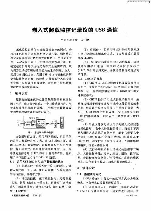
( ) U B接 口芯 片 采用 U B通 信模 块 ,该 模 4 S S
块 可 采 用 串 口 通 信 ,可 节 约 记 录 仪 主 控 芯 片 ( P 2 3 ) 的引脚 资源 ,并使 得 控 制 电路 更 加 简 L C 18 单 可靠 。
1 2 C 3 5的特点 . H 7
为完善 记录仪 管理 和统 计 能力 的重 要 问题 ,在 此 , 采用 U B通信方 案 ,利用 U B接 口将 记 录 仪 的历 S S
( )在字 节模 式 下 ,以 字节 为 基 本 单 位对 u 2
置和数 据存储 管理 的监控记 录仪 。
压
嘲
巷感 r . _ 器
力 传
( )u盘 文 件 读 写 模 块 用 于 向嵌 入 式 控 制 系 3 统 提供读 写 u 盘 中文 件 数 据 的接 口,而基 本 不 需
要 占用嵌 入 式 系统 的存 储 空 问 ,最 少 只需 要 几 个 字节 的 R M 和 几 百 字 节 的 代 码 。 该 模 块 基 于 A
《 起重运输机械》 2 0 ( ) 0 8 1
2 软 件 设 计
2 1 数 据读 写方式 .
C 35模块 对 u盘 文 件 的读 写 方 式分 为扇 区 H7 模式 、字 节模式 以及 数据 流模式 等 。
( )在 扇 区模 式 下 ,以扇 区 ( 扇 区通 常 是 1 每 5 2字节 ) 为 基 本 单 位 对 u 盘 文 件 进 行 读 写 ,所 1
无 需另置 电缆 ( 信线 ) 通 ,管
理人员 仅用 一 个 u 盘 ,便 可定 期 载 下所 有起 重 机 的运行数 据 ,且 携带 方便 ;
( ) 可 以热插 拔 在 下 载 数 据 时 ,无 需 重 复 2 “ 机 、将 井 口或 串 口电缆 接 上 、再 开 机 ” 这样 的 关 动 作 ,而是 直 接 在记 录仪 工 作 时 ,就 可 以将 u盘 插 上下载数 据 ;
基于USB接口的光照度记录仪的设计
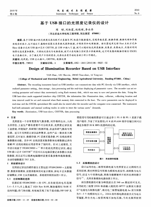
h d b t uo t n n a o k n d si r e e h a o s u e s e n s a oh a t mai a d ma u lw r ig mo e n od r t me tt e v r u s r ’d ma d . c o i
c r i g p r mee nd e ta td t me a i sn a h mor ik,whih wa a y t a e a d p o e st a a Usn he o d n a a tr a xr c a a mo ntrl u ig f s me y l y ds c se s o s v n r c s he d t . igt
关 键 词 : 照度 ;U B主从 接 口 ; H 7 B; 据 处 理 光 S C 35 数
中图分类号 : M 3 T 92
文献标识码 :A
文章编号 :0 2—14 ( 0 0 0 0 2 0 10 8 1 2 1 ) 6— 05— 2
De i n o lu i to c r e s d o B n e f c sg f Il m na i n Re o d r Ba e n US I t r a e
Ab t a t h e od n n t me t a e n US n e a e c n c mmu i ae d t t C d r cl i S n e a e s r c :T e r c r i gi sr u n s d o B i tr c a o b f n c t aa wi P ie t v a U B i tr c ,whc h y f ih ra i d p r me e et g,d t tr g ,d t rc s i g a d t e r a—i ip a i go a a t c c r e h e o d r a e e e l e a a trs t n z i aaso a e a ap o e sn n h e lt me d s lyn f r mer u v .T e r c r e n s t — p i c r
第一现场记录仪d500说明书
第一现场记录仪d500说明书
1、安装机器
在行程记录器中插入TF卡,以存储视频、图像或其他文件,将本机固定到原后视镜位置,在通过车充将本机与点烟器链接。
注意:布线时可将充电延长线沿挡风玻璃边缘敷设。
选配后置摄像头安装车辆后部,注意方向。
布线可沿车辆顶棚敷设。
安装完成后,将后摄像头插头接入记录仪后摄像头接口。
调整镜头位置,确保镜头与地面保持水平。
发动引擎,检查机器录像效果。
2、开启行车记录仪
按下【电源键】将行车记录器打开,或连接车载充电器,启动汽车本机即可自动开启。
3、电池充电和USB连接
(1)可以使用随增的车载充电器对记录器进行充电,正常接入电源后,屏幕顶部的电池电量显示符号变为充电符号。
(2)通过USB数据线把机器连接到电脑,连接成功后将自动弹出选择菜单,按【上翻键】和【下翻键】选择相应的功能,按【OK 键】执行操作。
testo 184 USB型 运输数据记录仪 使用手册说明书

testo 184 · USB型 运输数据记录仪 使用手册21 内容1内容1内容 (3)2安全与环境 (4)2.1.关于此文档 (4)2.2.确保安全 (4)2.3.保护环境 (4)3说明 (5)3.1.使用 (5)3.2.技术数据 (5)4产品描述 (15)4.1. LED 状况 (15)4.2.显示器(LCD) (16)4.3.按键功能 (17)4.4.重要信息和术语解释 (19)5产品使用 (21)5.1.配置数记录仪 (21)5.2.测量 (23)5.3.读取数据 (24)6产品维护 (26)6.1.更换电池 (26)6.2.清洁仪器 (27)7提示和帮助 (28)32 安全与环境2安全与环境2.1.关于此文档应用>本操作手册是本产品的一个重要组成部分。
>在使用之前仔细通读本文档并熟悉本产品。
要特别注意安全说明和警告,以避免人员受伤和产品损坏。
>请将本文档放在附近,以便在需要时可查阅。
>确保产品的后续用户能够阅读本操作手册。
2.2.确保安全>请正确操作本产品,本产品只能用于指定用途,并且在设定技术数据的参数范围内使用。
请不要强行操作。
>如果外壳损坏,请勿使用本产品。
>只可按照文件中的规定对此设备执行维护和修理工作。
应当严格地遵照规定步聚。
只能使用 Testo 原装备件。
2.3.保护环境>根据合理且合法的规范处理有问题的可充电电池/废弃电池。
>使用寿命到期后,请把本产品送至电子电气装置分类收集处(请遵循当地法律法规),或者返回 Testo 进行处理。
WEEE Reg. Nr. DE 7533435243 说明533.1. 说明使用testo 184 USB 型数据记录仪用于存储和读取单个测量值和测量序列。
它们是专为冷链产品的运输监控而设计。
温度和湿度测量值在整个测量程序持续期间被存储。
加速度测量值在整个测量程序持续期间被监控,并在超过设定的限制值时被存储。
风光58016款记录仪接线定义

风光58016款记录仪接线定义我们需要了解风光58016款记录仪的接口类型。
该记录仪采用了常见的USB接口和AV接口。
USB接口用于连接记录仪与电脑或电源适配器,而AV接口则用于与车载显示器连接,以实时观看记录仪的录像画面。
1. USB接口的接线方法:将记录仪的USB接口插入电脑的USB接口或者连接电源适配器的USB接口。
在接线过程中,要确保插头与插孔对应正确,避免插反或插歪导致接触不良。
正确连接后,电脑或电源适配器会自动识别并为记录仪充电或进行数据传输。
2. AV接口的接线方法:需要准备一根AV连接线。
将一端的黄色接口插入记录仪的AV接口,另一端的黄色接口插入车载显示器的AV接口。
同样地,确保插头与插孔对应正确,避免插反或插歪。
连接完成后,打开车载显示器,选择AV输入信号源,即可观看记录仪的录像画面。
需要注意的是,不同车载显示器的接口类型和位置可能会有所不同,但接线方法基本相似。
在接线过程中,可以参考车载显示器的说明书或者咨询专业人士进行正确接线。
除了USB接口和AV接口,风光58016款记录仪还可能配备其他接口,如HDMI接口、TF卡接口等。
这些接口的接线方法与USB接口和AV接口类似,只需将对应接口插入相应设备即可。
在进行接线时,需要注意以下几点:1. 确保记录仪和相关设备处于关闭状态,避免电流冲击或短路。
2. 插拔接线时要轻柔,避免用力过猛导致接口损坏。
3. 接线完成后,可以进行简单的测试,确保设备正常工作。
总结起来,风光58016款记录仪的接线方法包括USB接口和AV接口的连接。
正确的接线方法能够保证记录仪的正常工作,提供清晰稳定的录像画面。
在进行接线时,要仔细阅读记录仪和相关设备的说明书,并遵循正确的接线步骤。
如果遇到问题,可以咨询专业人士或厂家客服寻求帮助。
通过正确的接线,我们能够充分发挥风光58016款记录仪的功能,为我们的行车提供更多的保障。
YK-214无线系列智能开关量记录仪使用说明书
YK-214无线系列智能开关量记录仪使用说明书北京宇科泰吉电子有限公司一、概述YK-214LCD系列智能无线开关量记录仪,采用先进的微电脑芯片及技术,与现场的无线开关发射器配套使用,对现场开关量信号、电平信号进行测量显示、存储及现场查询,可以通过移动硬盘导出数据用Excle文件软件打开查询,浏览等。
YK-214LCD系列智能无线开关量仪表可以对多套设备运行进行时间监测、记录等,并能根据系统时间把开关量的闭合、断开时间记录下来。
用来记录设备的开关次数与开关时间,通过按键浏览记录数据。
每路开关量可以记录3万组数据,数据包含开关量动作的时间(年月日)、状态,数据记录采用先进先出循环记录方式。
仪表内置硬件时钟,停电不影响时钟运行。
YK-214LCD智能无线开关量记录仪可根据客户要求做成脉冲信号,TTL电平信号、SSI编码器信号输入的记录仪,可带RS232或RS485的通讯接口与PLC,计算机等现场工业设备连接构成工业测控系统。
仪表内部带有可充电电池供时钟运行,仪表长期不使用时建议每六个月通电24小时使电池充电。
二、主要技术指标1·输入信号:无源开关量接点,脉冲信号,TTL电平等2·显示方式:宽温蓝屏白字高亮LCD显示屏。
3·记录数据容量:每通道可记录存储30000条。
4·报警输出:仪表可以带多达16个继电器报警输出,220V/3A。
(订货说明)5·通讯输出:隔离通讯接口RS485(标准Modbus-RTU通讯协议)波特率1200~9600bps内部自由设定6·工作环境:温度0~50℃湿度<85%RH7·电源:开关电源85~265V AC或DC24V 功耗<4W8·外形尺寸:160×80×120mm(盘装横式) 80×160×120mm(盘装竖式)320×120×270mm(台式)可带串行通讯接口,可与各种带串行接口的设备进行双向通讯,组成网络控制系统。
开关量记录仪带通讯

一、概述YK-214LCD系列开关量记录仪,采用先进的微电脑芯片及技术,对现场开光量信号进行测量显示、存储及通讯,可以采用128*64宽温液晶显示或4排LED数码管显示。
(用液晶显示请书面说明)YK-214LCD系列开关量仪表具有6路开关量输入,并能根据系统时间把开关量的打开、关闭时间记录下来。
用来记录设备的开关停次数与开关时间,通过按键浏览记录数据。
每路开关量可以记录950组数据,数据包含开关量动作的时间(年月日)、状态。
仪表内置硬件时钟,停电不影响时钟运行。
YK-214LCD记录仪可根据客户要求做成脉冲信号,TTL电平信号输入的记录仪,可带RS232或RS485的通讯接口与PLC,计算机等现场工业设备连接构成工业测控系统。
仪表内部带有可充电电池供时钟运行,仪表长期不使用时建议每六个月通电24小时使电池充电。
二、主要技术指标1·输入信号:无源开关量接点,脉冲信号,TTL电平等2·显示方式:4排LED高亮度数码显示,宽温蓝屏白字高亮LCD显示屏。
3·报警输出:仪表可以带多达16个继电器报警输出,220V/3A。
(订货说明)4·通讯输出:隔离通讯接口RS485/RS232(标准Modbus-RTU通讯协议)波特率1200~9600bps内部自由设定5·工作环境:温度0~50℃湿度<85%RH6·电源:开关电源85~265V AC或DC24V 功耗4W以下7·外形尺寸:160×80×120mm(盘装横式) 80×160×120mm(盘装竖式)320×120×270mm(台式)四、操作说明I、按键说明■—在设置状态和浏览状态下,按该键选择要查看参数。
En—在设置状态时,用于存贮参数的新设定值并选择下一个设定参数。
▢—在设置状态时,用于增加设定值。
或查询报警状态。
▼—在设置状态时,用于减少设定值。
K-20USB隐藏式记录仪使用说明书
K-20USB隐藏式记录仪使用说明书1、电源键/摄像头补光灯功能一:开关机功能在关机状态下,长按【电源键】并保持3秒钟,可开启本机电源,机器开始工作。
在开机状态下,长按【电源键】并保持3秒钟,本机自动保存录像文件及用户设置并关机。
功能二:摄像头补光灯功能在待机状态下,短按【电源键】,可进行补光灯打开/关闭/自动三种模式的切换。
自动模式下,补光灯由摄像头感应光的亮度来控制。
2、模式键/菜单键/紧急录像锁定键功能一:模式切换功能在待机状态下,短按【模式键】,可在不同模式(录像/拍照/回放)之间进行切换。
功能二:菜单功能在待机状态下,长按【菜单键】进行主菜单功能设置表,短按【上翻键】或【下翻键】,选择需要设置的选项,短按【确认键】确认。
设置完成后,短按【菜单键】直至退出菜单设置功能。
(菜单设置方法在录像模式、拍照模式、回放模式中均相同)功能三:紧急锁定功能在录像模式中,如果想保护当前视频不会被覆盖,短按【菜单键】启动紧急锁定功能,此时,屏幕上方出现锁文件图标,则将事故发生时的当前正在录制的影像保存为一个特殊影像,这个影像不会被覆盖。
3、上翻键/移动测速/快退功能一:上翻页功能在菜单设置和回放模式中为上翻页功能。
功能二:移动侦测功能三:快退在回放模式上,短按【上翻键】可以快退。
4、下翻键/静音键/快进/停车模式功能一:下翻页功能在菜单设置和回放模式中为下翻页功能。
功能二:关闭录音功能在录像模式中,短按【下翻键】可关闭录音功能,此时屏幕右下方话筒变为禁止图标,表示已经关闭录音功能。
再次短按可开启录音,图标显示为开启录音。
功能三:快进在回放模式下,短按【下翻键】可以快进。
功能四:停车监控在待机模式下,长按【下翻键】可以打开或关闭停车模式功能,左下角图标会有相应的变化。
5、录像键/拍照键/确认键/屏幕背光灯开关键功能一:启动/关闭录像功能在录像模式下,短按【确认键】开始录像,再次短按【确认键】可停止录像。
功能二:拍照键在拍照模式下,短按【确认键】一下可拍摄一张照片。
USB采集仪使用中英文说明书
查看开门记录的步骤第一步:制一张记录卡记录卡就是任意一张TEMIC卡,放在发卡器的感应区 点击。
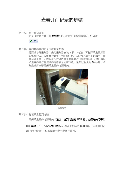
第二步:将门锁的开门记录下载到采集器需要准备好采集器,先给采集器安装4接7#电池,再打开采集器后面的电源开关,采集器“嘀嘀”声后红灯亮,在门锁上刷一下记录卡,再将记录卡拿开,然后在3秒钟内将采集器靠近门锁的感应区,如下图,采集器的红灯有规律的闪烁表示正在下载,采集过程大约30秒钟。
采集完成后立即关闭采集器的电源开关。
采集姿势第三步:将记录上传到电脑关闭采集器的电源开关(注意:连到电脑的USB前,必须先关闭采集器的电源,并一直保持关闭状态),再连上电脑的USB端口;点击开门记录下的“读取”,根据提示一步一步操作即可。
Steps of opening recordsStep 1: Produced a record card.The record card is any one TEMIC card, put it on the sensitive area of the card dispenser Click。
Step 2: locks the door records downloaded to the collectorNeed to be ready for the collector, installed 4 pieces of 7 # battery in collector, open power switch behind the collector, the red light collector "Didi" sound, swipe the lock on the record card, then put record card away, and then to collect sensitive area near the door locks within 3 seconds, the regular flashing red light on the following figure, the acquisition is being downloaded, the acquisition process for about 30 seconds. The acquisition closed immediately after the completion of the acquisition of the power switch.Acquisition postureStep 3: upload the recording to your computerTurn off the acquisition power switch (Note: before connected to the computer's USB, the power of the collector must be turned off, and has remained off), and then connected to the computer's USB port; click "read" open the door to record, according to the prompt step instructions to operate .。
记录仪 USB 驱动使用说明说明书
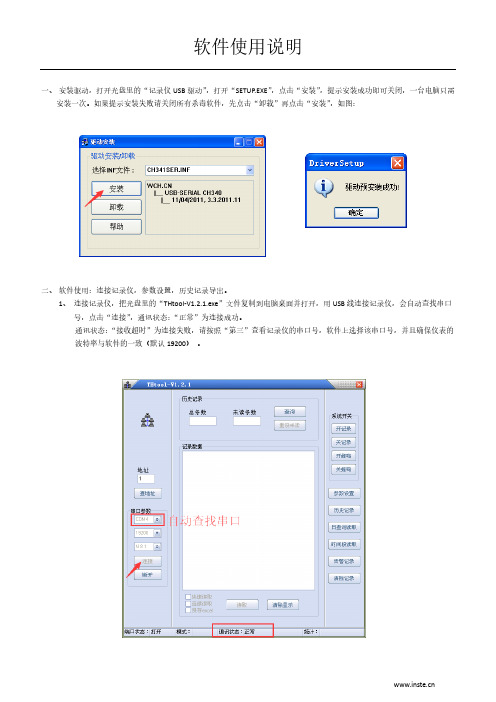
一、安装驱动,打开光盘里的“记录仪USB驱动”,打开“SETUP.EXE”,点击“安装”,提示安装成功即可关闭,一台电脑只需
安装一次。
如果提示安装失败请关闭所有杀毒软件,先点击“卸载”再点击“安装”,如图:
二、软件使用:连接记录仪,参数设置,历史记录导出。
1、连接记录仪,把光盘里的“THtool-V1.2.1.exe”文件复制到电脑桌面并打开,用USB线连接记录仪,会自动查找串口
号,点击“连接”,通讯状态:“正常”为连接成功。
通讯状态:“接收超时”为连接失败,请按照“第三”查看记录仪的串口号,软件上选择该串口号,并且确保仪表的波特率与软件的一致(默认19200)。
2、参数设置,首次使用要设置相关参数,主要设置:校准时间、记录间隔、温湿度上限下限告警值、开记录。
3、历史记录导出,按步骤读取完后会自动生成Excel文件。
已读过的记录数据想要再次读取或者只想读取最近多少天的数据(按记录间隔算一下就知道了),可以在“未读条数”
输入预读的条数,点“重设未读”便可。
“日查询读取”可以指定读取某天的记录,“时间段读取”可以指定读取某个时间段的记录。
三、如果电脑存在多个串口,自动查找不到串口号,按下面步骤查看,右击“我的电脑”→单击“管理”→单击“设备管理器”
→单击“端口”便可查看。
四、清除记录,软件连接成功后,点清除记录,提示输入密码,密码为“4660”。
一般不用清除记录,存满后会自动覆盖。
易测USB数据记录仪EL-GFX-1产品说明书
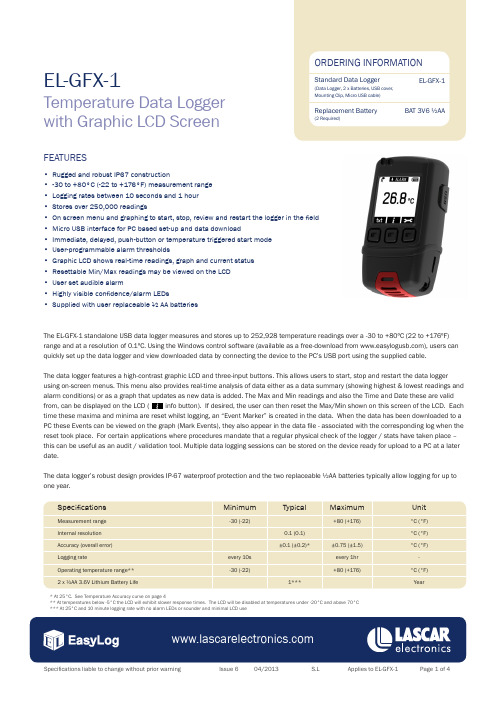
The EL-GFX-1 standalone USB data logger measures and stores up to 252,928 temperature readings over a -30 to +80ºC (22 to +176ºF) range and at a resolution of 0.1ºC. Using the Windows control software (available as a free-download from ), users can quickly set up the data logger and view downloaded data by connecting the device to the PC’s USB port using the supplied cable.The data logger features a high-contrast graphic LCD and three-input buttons. This allows users to start, stop and restart the data loggerusing on-screen menus. This menu also provides real-time analysis of data either as a data summary (showing highest & lowest readings and alarm conditions) or as a graph that updates as new data is added. The Max and Min readings and also the Time and Date these are valid from, can be displayed on the LCD ( info button). If desired, the user can then reset the Max/Min shown on this screen of the LCD. Each time these maxima and minima are reset whilst logging, an “Event Marker” is created in the data. When the data has been downloaded to a PC these Events can be viewed on the graph (Mark Events), they also appear in the data file - associated with the corresponding log when the reset took place. For certain applications where procedures mandate that a regular physical check of the logger / stats have taken place – this can be useful as an audit / validation tool. Multiple data logging sessions can be stored on the device ready for upload to a PC at a later date.The data logger’s robust design provides IP-67 waterproof protection and the two replaceable ½AA batteries typically allow logging for up to one year.EL-GFX-1Temperature Data Logger with Graphic LCD ScreenFEATURES• Rugged and robust IP67 construction• -30 to +80°C (-22 to +176°F) measurement range • Logging rates between 10 seconds and 1 hour • Stores over 250,000 readings• On screen menu and graphing to start, stop, review and restart the logger in the field • Micro USB interface for PC based set-up and data download• Immediate, delayed, push-button or temperature triggered start mode • User-programmable alarm thresholds• Graphic LCD shows real-time readings, graph and current status • Resettable Min/Max readings may be viewed on the LCD • User set audible alarm• Highly visible confidence/alarm LEDs• Supplied with user replaceable ½ AA batteries* At 25°C. See Temperature Accuracy curve on page 4** At temperatures below -5°C the LCD will exhibit slower response times. The LCD will be disabled at temperatures under -20°C and above 70°C *** At 25°C and 10 minute logging rate with no alarm LEDs or sounder and minimal LCD useLascar’s Easylog USB control software is available to download from . Easy to install and use, the control software runs under Windows XP, Vista and Windows 7. The software is used to set-up the data logger as well as download, graph and export data to Excel. Each stored logging session is saved as a separate file.The software allows the following parameters to be configured:• Logger name• Measurement parameter (ºC or ºF)• Logging Rate (user-selectable between 10 seconds and 1 hour) • High and low temperature alarms• Immediate, delayed, push-button or temperature triggered start mode • Disable or enable LEDs and sounder with delayed activation • Display and backlight behaviour after button pressThe latest version of the control software may be downloaded free of charge from EL-WIN-USB (CONTROL SOFTWARE)DIMENSIONSAll dimensions in mm (inches)88.0 (3.46)48.5 (1.91)30.5 (1.20)BATTERY REPLACEMENTWe recommend that you replace the batteries every 12 months, or prior to logging critical data.The EL-GFX-1 does not lose its stored readings when the batteries are discharged or when the batteries are replaced; however, the data logging process will be stopped. If the batteries are changed within a 2 minute window the EL-GFX-1 will retain its settings (internal clock and logging mode). This will allow logging to be restarted without additional connection to a PC via USB.Only use 2 x 3.6V ½AA lithium batteries. Do not mix battery types and do not mix new and old batteries. Before replacing the batteries, unplug the EL-GFX-1 from the PC.WARNINGHandle lithium batteries carefully, observe warnings on battery casing. Dispose of in accordance with local regulations.MENU BUTTON FUNCTIONS AND LED SCREEN INDICATIONButton Time ValueModule House Whiteparish, Salisbury Wiltshire SP5 2SJ UKT +44 (1794) 884567 F +44 (1794) 884616 ****************.uk 4258 West 12th StreetEriePA 16505USAT +1 (814) 835 0621F +1 (814) 838 8141*******************************8th Floor, China Aerospace Centre143 Hoi Bun RoadKwun Tong, KowloonHONG KONGT +852 2797 3219F +852 2343 6187*******************.hkTEMPERATURE ACCURACY。
凯富隆usb行车记录仪安装文件
凯富隆usb行车记录仪安装文件凯富隆USB行车记录仪是一种高性能的车载视频录像装置,广泛应用于汽车等交通工具的行车记录和事故证据采集。
安装文件是为了方便用户快速、准确地安装和使用该行车记录仪而提供的一种指导文档。
首先,安装文件应包含使用前的准备工作,例如说明所需的硬件设备和操作系统的要求,以及安装所需的驱动程序和其他支持软件的下载链接。
此外,还应详细介绍如何正确连接行车记录仪与车辆的电源和信号线,以确保设备正常工作。
其次,安装文件中应包含详细的安装步骤,从打开安装包开始,逐步指导用户完成各种安装操作。
例如,安装文件可以指导用户如何正确插入内存卡并格式化,以及如何正确安装行车记录仪在车辆上的位置。
同时,安装文件也应提供一些实用的技巧和注意事项,例如如何选择合适的安装位置以获得最佳的录像效果和视野范围。
此外,安装文件还应包含配置和调试行车记录仪的步骤。
这包括设置日期和时间以及其他常见的参数选项,如录像分辨率、循环录像、碰撞感应等。
通过详细而简明的说明,用户可以轻松地调整和配置行车记录仪以满足自己的需求。
最后,安装文件还应提供用户常见问题的解答和故障排除。
例如,当行车记录仪无法正常启动或录像显示有问题时,安装文件应提示用户如何重新设置和修复设备。
此外,安装文件还应提供售后服务的联系方式,以便用户在遇到无法解决的问题时获得技术支持。
综上所述,凯富隆USB行车记录仪的安装文件应具备全面、详细、易懂的特点,以方便用户正确、快速地安装和使用该设备。
只有提供了完善的安装文件,用户才能更好地理解和操作行车记录仪,从而确保其正常运行并在需要时提供有效的证据。
数据记录仪操作方法
数据记录仪操作方法
1. 首先确保数据记录仪已经安装好电池或接通了电源;
2. 按照数据记录仪的说明书找到启动按钮,在按下启动按钮后,等待数秒钟,直到数码显示屏上出现操作指引;
3. 根据操作指引,设置所需的参数,例如采样率、记录间隔、记录时间等。
这些参数依据用户需要和记录仪的性能进行选择,可以根据实际需求进行灵活配置;
4. 将传感器或探头连接到数据记录仪上,确保连接正确无误;
5. 在记录开始之前,检查一下数据记录仪和传感器是否正常工作,如传感器的灵敏度、分辨率等是否符合要求;
6. 开始记录数据,将数据记录仪放置在所记录的场所,确保其位置固定不会出现移动或晃动。
7. 记录数据的时间结束后,按下停止按钮,在数据记录仪的数码显示屏上可以查看到录制的数据。
需要导出记录的数据,可以通过相关的软件或数据线连接到电脑上,将数据导出并进行处理分析。
8. 记录结束后,关闭数据记录仪,取出传感器或探头,将设备清洗和存放,以
备下一次使用。
DW-USB型号USB数据记录仪产品说明说明书
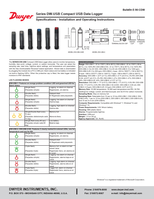
The SERIES DW-USB Compact USB Data Logger allow users to monitor temperature, humidity, dew point, voltage, current, or carbon monoxide. The user can select the sampling rate, start time, high/low alarm settings, and temperature unit parameters with the free downloadable Windows ®-based application. Stored data is downloaded by plugging the module into a PC’s USB port. Alarm status and low battery is indicated via built-in flashing LED’s. When the protective cap is fitted, the data logger resists moisture to IP67 standards.LED FLASHING MODESWindows ® is a registered trademark of Microsoft Corporation.MODEL DW-USB-XTERMINAL BLOCK CAPCLIP CLIPMODEL DW-USB-CASEPrinted in U.S.A. 11/17FR# 443584-00 Rev. 6©Copyright 2017 Dwyer Instruments, Inc.BATTERY INSTALLATIONBefore using the data logger, you will need to insert the 3.6 V 1/2 AA battery provided, following the instructions below.SOFTWARE INSTALLATIONThis software must be installed prior to the USB Driver. Please follow the instructions below then refer to the USB Driver Installation based on the Windows ® operating system you are using.1. Visit our website /DW-USBSoftware and click on thedownload link. If the download folder doesn’t open directly, go to your computer’s “Downloads” folder and double-click on the “EasyLogUSBV610_Dwyer” folder.2. Double-click on “setup” then follow the on screen instructions to complete the Configuration Software Installation.3.An EasyLog USB icon will now be placed on your desktop.USB DRIVER INSTALLATIONWindows ® 7/Windows ® 8/Windows ® 10 Operating Systems:You must install the Configuration Software as instructed in the previous section before going through these steps.1. Insert the USB data logger directly into a USB port on the computer. Installation screens should automatically appear.2. Follow the on screen instructions to complete the Configuration Software Installation. If a compatibility error window appears, click ˝Continue Anyway˝. Note: This will not cause any adverse changes/effects on your computer.3. You can now begin using our data logger by double clicking on the EasyLog USB icon on your computers desktop.Carbon Monoxide Safety NoticeThe DW-USB-6 is not a suitable substitute for a domestic or industrial carbon monoxide detector/alarm.MAINTENANCEUpon final installation of the Compact DW-USB Data Logger, no routine maintenance is required. Leaving the logger plugged into your computer for an extended period of time will considerably lower its battery life. The Series DW-USB is not field serviceable and should be returned if repair is needed (field repair should not be attempted and may void warranty). Be sure to include a brief description of the problem plus any relevant application notes. Contact customer service to receive a Return Goods Authorization number before shipping.。
usb安卓行车记录仪原理
usb安卓行车记录仪原理
USB安卓行车记录仪原理:行车记录仪是一种基于安卓操作
系统的设备,通过USB接口连接到车辆电源上,并使用相机
模组来记录行车过程中的视频和音频。
它的基本原理是将录制的数据存储到SD卡中,然后通过USB接口传输到连接的安
卓设备上。
具体而言,USB安卓行车记录仪包含一个摄像头和一个数据
处理单元。
摄像头负责实时拍摄前方的道路和车辆情况,并将视频数据传输给数据处理单元。
数据处理单元将视频数据压缩,并通过USB接口传输到连接的安卓设备上。
USB安卓行车记录仪的数据处理单元通常包含一个特殊的芯片,用于视频数据的压缩和存储。
这些压缩算法通常采用
H.264或者H.265标准,以便实现高质量的视频录制并减小存
储空间占用。
此外,USB安卓行车记录仪还可以配备GPS模块,用于记录
车辆的行驶轨迹和车速等信息。
这些数据可以与视频数据结合在一起,提供更全面的行车记录。
在使用USB安卓行车记录仪时,用户只需将其插入车辆的
USB接口并连接到安卓设备上,就可以实时查看和存储行车
过程中的视频数据。
用户可以通过相应的安卓应用程序来管理和观看录制的视频,并可以选择将其存储到SD卡或者安卓设
备的内部存储器中。
总结来说,USB安卓行车记录仪通过摄像头和数据处理单元实现对行车过程的视频录制和存储,并通过USB接口传输到安卓设备上,为用户提供行车安全和证据保全的功能。
USB 分析仪使用说明.
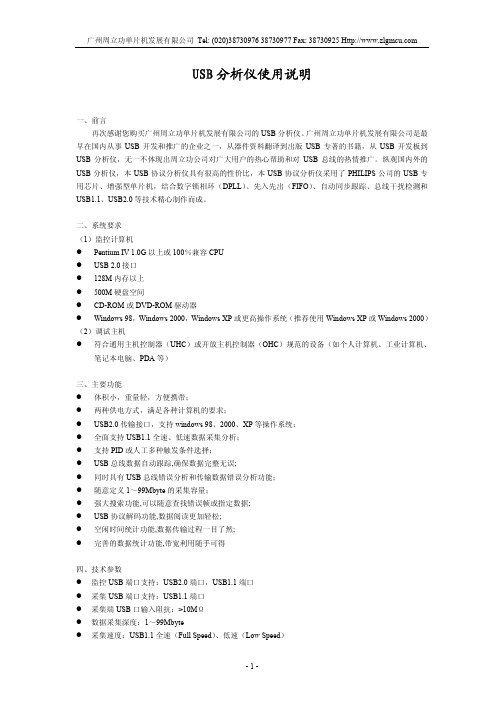
图 11 设备管理器窗口 安装完软件和驱动程序后,打开 USBAnalyser 软件,其菜单如图 12 所示。
图 12 USB 分析仪菜单 菜单的功能说明如下:
文件菜单 文件菜单主要为 USB 分析仪的文件操作选择,共有 8 个选项。如图 13 所示:
图 29 解码设备请求对话框
- 10 -
广州周立功单片机发展有限公司 Tel: (020)38730976 38730977 Fax: 38730925 如图 30 为一个对 Packet #1318 进行解码的结果。
图 18 显示格式设置 记录选项:
设置采集的触发条件、采集端的速度和采集数据的深度,如图 19 显示。
图 19 数据记录选项 -7-
广州周立功单片机发展有限公司 Tel: (020)38730976 38730977 Fax: 38730925 其中触发条件为选择 PID 触发或人工触发来开始数据采集。可供选择的 PID 触发选项有:OUT、IN、
图 7 寻找驱动程序 如果使用 Windows XP 或 Windows 2000 操作系统,会有图 8 的提示。
图 8 Windows 徽标提示 点击仍然继续,就开始复制驱动程序,安装完后,会有如图 9 的提示。
图 9 完成新硬件向导 -4-
广州周立功单片机发展有限公司 Tel: (020)38730976 38730977 Fax: 38730925 点击完成就可以了,且右下方会出现如图 10 的新硬件安装完成的提示。
监控计算机运行usbanalyser分析软件调试主机个人计算机工业计算机笔记本电脑pda等usb调试设备usb分析仪powermonitorrunusbpowusbausbbresetusb连接线usb连接线usb连接线usb分析仪的连接六软件的安装与使用在光盘的software目录里双击setupexe然后应用程序和驱动程序都会安装上了
BESANTEK USB数据记录仪指南说明书

BESANTEK USB Data Logger Instructional Manual (BST-DL10, BST-DL13, BST-DL14)CONTENTSChapter B Data Logger Hardware (1)1.1Introduction ..........................................................................................................................11.2Features ................................................................................................................................11.3Application ............................................................................................................................11.4BESANTEK USB Data Logger Model ......................................................................................11.5BESANTEK USB Temperature Data Logger Appearance ......................................................21.6BESANTEK USB Temperature Data Logger Screen ...............................................................21.7BESANTEK USB Temperature &Humidity Data Logger Appearance ...................................31.8BESANTEK USB Temperature &Humidity Data Logger Screen ............................................31.9Button ...................................................................................................................................41.10Install Battery ......................................................................................................................41.11Fix USB Data Logger ............................................................................................................4Chapter 2.BSTSoftware . (5)2.1The Requirement of the Computer Hardware .....................................................................52.2Install Driver &Software .......................................................................................................52.3Setting the logger’s properties to start a new measurement..............................................62.4Properties Description ..........................................................................................................72.5Download the Records after a Measurement......................................................................82.6Data Listing Window .............................................................................................................92.7Exporting Logs from BST Software ........................................................................................92.8Delete Records in the Logger ..............................................................................................102.9Check the Save File in File List ............................................................................................10Chapter 3.Attention ..........................................................................................................................11Chapter 4.FAQ . (11)4.1LCD Screen Dim ...................................................................................................................114.2LCD Screen Display “FUL”...................................................................................................114.3Data &Time Error ...............................................................................................................114.4Software "Runtime Error"...................................................................................................114.5Check COM Port Number (11)BESANTEK USB Data Logger Instructional Manual(BST-DL10, BST-DL13, BST-DL14)B Data Logger Hardware1.1IntroductionBESANTEK USB Data logger has USB interface,enjoying elegant appearance and compact construction,specially designed for refrigerator and cold-chain transportation as well as container transport applications.BESANTEK USB Data logger adopts friendly USB interface, friendly mounting bracket and the screws.BESANTEK USB Data logger can show temperature/temperature and humidity simultaneously as well as the battery indication.The OK key can help to check the Max/Min/Current value and the upper and lower limits.1.2FeaturesWaterproof and dustproof standard IP67,resisting moisture and dust.Temperature and humidity limit can be set.LED lights when the setting value being exceeded.Lower consumption design,1/2AA3.6V Li battery,working for12months and easy to replace battery.(Logging Interval:600s)Transfer logging data to PC through software and can be saved as different types to ensure the existence.The high accuracy sensor was produced by Switzerland,Size(L x H x D):126mm x34mm x28mm1.3ApplicationCold Chain TransportationContainersOutdoor Stevenson Screen1.4BESANTEK USB Data Logger Model1.5BESANTEK USB Temperature Data LoggerAppearance①LCD Screen ⑥Battery Replacement Position.②Button⑦Waterproof Transparent Cover ③LED Warming Light When the Temperature Value Exceeds theSetting Limits.⑧Fixed Bracket ④USB Connection Port ⑨Label⑤Waterproof Ring1.6BESANTEK USB Temperature Data Logger Screen①Display the High Limit ⑤Display the Maximum Value in Records②Display the Low Limit ⑥Symbol display shows being the logging status.③Battery power indication.⑦Temperature Value ④Display the MinimumValue inRecords⑧Temperature Unit(℃or ℉)1.7BESANTEK USB Temperature&Humidity Data LoggerAppearance①LCD Screen⑥Battery Replacement Position.②Button⑦Waterproof Transparent Cover⑧Fixed Bracket③LED Warming light When theTemperature or Humidity ValueExceeds the Setting Limits.④USB Connection Port⑨Label⑤Waterproof Ring1.8BESANTEK USB Temperature&Humidity Data Logger Screen①Display the High Limit⑤Battery power indication.②Display the Low Limit⑥Units symbol display℃or℉%RH⑦Value③Display the Maximum Value inRecords④Display the Minimum Value inRecords1.9ButtonOK Button1.Press this button for long to5seconds can turn on/off the logger.2.Check the MAX;MIN;High&Low values as well as the current value in the workingstatus.1.10Install Battery1.Open the Battery Cover2.Install Battery1.11Fix BESANTEK USB Data Loggere Screw to Fix the Bracket onto the Wall.2.Install the Data Logger.Chapter2.BSTSoftware2.1The Requirement of the Computer Hardware1.OS:Windows XP/Vista/7/8(32/64bit)2.CPU:1.6GHz3.Physical Memory:512MB4.Hard-drive Space:4GBB Port:12.2Install Driver&Software1.Install DriverNotice:Windows64bit please install64bit-driver.2.Install BSTSoftwareNotice:Please Install BSTSoftware in D:\2.3Setting the logger’s properties to start a new measurement.1.Connect the data logger to the computer.12.Running BSTSoftware on the PC.3.From the toolbar select Connect.24.Read the logger’s properties.5.Set the properties.6.Sync the properties&time.(The PC time will be synchronized to the logger as well.)7.From the toolbar select Disconnect8.Unplug the logger from the Computer,and then the logger is in Standby mode3.9.Press OK button on the logger,turn on the Data Logger and start recording.1The windows operating system cannot handle USB devices being unplugged and plugged back too fast.When unplugging the logger,wait for about5seconds before plugging it in again.If you unplug and plug back a device too quickly,the computer may stop recognizing any USB devices on that port. If this happens you will have to restart the computer.This is a windows USB problem and is not related to BSTSoftware.2If more than one logger is connected to your computer at the same time,the program will ask you to choose COM port manually.3The logger has three modes:1.LOG:In the mode,the logger samples and records data timely.2. Standby:In the mode,the logger stops to sample and record,and the LCD display is OFF.3.OFF:In the mode,the logger stops to sample and record,and the LCD display is off.BSTSoftware cannot connect to the logger also.2.4Properties DescriptionProperty Text DescriptionName English letters orNumbersName of the loggerSN10Characters Must be the same as the one in the label oflogger.Sampling Interval(s)Number from1to240Sampling frequency in LCD screen Logging Interval(s)Number from2to86400Logging frequency.Logs The count of records in the memory. Capacity The total capacity of the logger’s storage. Start Mode Start Now Start log when the Logger was turn ON.Delay Start Wait Delay Time then start log.Timing Start Start log when Delay Time:HHMMSSe.g.170000means17:00:00Delay Time Input a Delay Time or Timing Time.High&Low Limit CH1:TemperatureCH2:Humidity When the value over the limit,the buzz will sounds an alarm.Offset4Input positive number to decrease the value.Input negative number to increase the value.4Calibrate the logger:The logger is factory calibrated to an accuracy given in the device specifications. However,there may be times when you wish to adjust the calibration of your logger.BSTSoftware provides you with the ability to perform a single point offset calibration.This calibration can be usedto increase the accuracy of the logger for a restricted data range.2.5Download the Records after a Measurement.10.Connect the data logger to a free USB port on the computer.11.Running BSTSoftware on the PC.12.From the toolbar select Connect.13.From the toolbar select DownloadOnce the data is transferred from the logger to the PC,the data graph will be displayed. The graph display will be blank if there are not any logs.Tips:Press and hold the left mouse button to drag a box,when the left mouse button is released,the graph will be redraw with the data in the selected rectangle area.Click right button,then the graph will be redrawing with all the data in the logs file.2.6Data Listing WindowClick"Data List"button on the toolbar,and then the data listing window is shown below. Channel3unit is Dew Point.The Value is calculated from temperature&humidity.The data pane lists the data samples collected by the logging device.The column width of each column is adjustable by using the left mouse button and dragging the column the desired width.2.7Exporting Logs from BSTSoftware:Export data list to an Excel file.:Export data list to a PDF file.:Export graph to a BMP file.2.8Delete Records in the Logger14.From the toolbar select Delete52.9Check the Save File in File List15.From the toolbar select Filelist.616.Click to open the file.Double click left mouse button,then the selected file is opened.Click right mouse button,a popup menu is shown as below,you can rename or delete or log file.The save file is saved in the BSTSoftware software’s installation path in the PC’s hard driver.5Clear the logger's memory.It will not affect downloaded file.6These files are located in the installed path of BSTSoftware.Chapter3.AttentionBESANTEK USB Data logger water proof level is IP67.Do not put it into the water.BESANTEK USB Data logger plastic shell is ABS,flame retardant,not resistant to acid and alkali.If repair is needed,only authorized technician could do the repair.The instrument configuration by1x ER14250lithium battery(3.7V)is not rechargeable.USB power supply(5V)cannot let the Data Logger work.Chapter4.FAQ4.1LCD Screen DimReason:Insufficient battery or the environment temperature is too low or too high.Solution:In the case of insufficient battery,please replace the battery.If resulted from environment temperature,please immediately take the logger out of the environment.4.2LCD Screen Display“FUL”Reason:The data is full of the data logger’s flash chip.Solution:Connect the data logger to a computer.Download the data from the data logger.Delete the data(clear the flash chip)in the data logger by BSTSoftware.4.3Data&Time ErrorReason:The battery level is lowThe data logger is not synchronous properties,before start recording.Solution:Replace the battery.Please sync the properties,before start recording.4.4Software"Runtime Error"Reason:OS forbid software creating files.Solution:Run the program(software)as an administrator.Install software in Disk D:\A data logger name cannot contain any of the following characters:\/:*?"<>|Software’s installation path cannot include Chinese character or unknown character. 4.5Check COM Port NumberPress“Win”+“R”in keyboard->Run"devmgmt.msc"to Open"Device Manager"in Windows->Expand"Ports(COM&LPT)"->"USB-SERIAL CH340(COM No.)"is the Data Logger。
智慧眼记录仪使用说明

智慧眼记录仪使用说明一、产品概述智慧眼记录仪是一种高清晰度、多功能的便携式摄像设备,主要用于记录行车过程中的影像和声音,并能够提供安全驾驶辅助功能。
本记录仪具有小巧轻便、操作简单、录像稳定等特点,适用于各类车辆的安装和使用。
二、产品组成智慧眼记录仪由以下几部分组成:1.主机:包含摄像头、录像芯片、控制面板等核心部件,负责实时录制和存储影像和声音;2.显示屏:用于观看录制的视频和设置相关参数;3.电源适配器:提供电源支持,可通过车载电源或者USB接口供电;4.安装支架:用于固定记录仪在车内的位置;5.数据线:用于连接记录仪与电脑、电视等外部设备传输数据。
三、使用方法1.安装:首先选择一个合适的位置安装智慧眼记录仪,一般建议安装在车内离驾驶员较近的位置,如挡风玻璃下方。
使用安装支架将记录仪固定好,确保其稳定性。
然后将电源适配器插入车载电源插座或USB接口,连接数据线并插入记录仪和电脑、电视等设备之间。
2.开机:按下电源按钮,智慧眼记录仪将开始自检,并在显示屏上显示当前状态。
待显示屏显示正常后,即可开始使用。
3.录像:在行车过程中,智慧眼记录仪会自动录制影像和声音。
可以通过设置菜单调整录像分辨率、帧率等参数。
录像文件将以时间为单位进行保存,并自动覆盖最早的文件,确保存储空间的充分利用。
4.拍照:除了录像功能外,智慧眼记录仪还具备拍照功能。
在录像过程中,按下快门按钮即可进行拍照操作。
5.循环录制:智慧眼记录仪支持循环录制功能,即当存储空间不足时,会自动覆盖最早的文件,以保证持续录制。
用户可以根据需要设置循环录制的时间段。
6.碰撞感应:智慧眼记录仪配备了碰撞感应功能,当发生碰撞或急刹车等情况时,记录仪会自动保存紧急事件的录像文件,并锁定该文件,不会被循环覆盖。
7.查看和导出:通过连接数据线,将智慧眼记录仪与电脑或电视等设备连接后,即可查看和导出录像和照片文件。
用户可以选择按时间、事件等方式进行查找和管理。
- 1、下载文档前请自行甄别文档内容的完整性,平台不提供额外的编辑、内容补充、找答案等附加服务。
- 2、"仅部分预览"的文档,不可在线预览部分如存在完整性等问题,可反馈申请退款(可完整预览的文档不适用该条件!)。
- 3、如文档侵犯您的权益,请联系客服反馈,我们会尽快为您处理(人工客服工作时间:9:00-18:30)。
一、概述
YK-214LCD系列开关量记录仪,采用先进的微电脑芯片及技术,对现场开光量信号进行测量显示、存储及通讯,可以采用128*64宽温液晶显示或4排LED数码管显示。
(用液晶显示请书面说明)
YK-214LCD系列开关量仪表具有6路开关量输入,并能根据系统时间把开关量的打开、关闭时间记录下来。
用来记录设备的开关停次数与开关时间,通过按键浏览记录数据。
每路开关量可以记录950组数据,数据包含开关量动作的时间(年月日)、状态。
仪表内置硬件时钟,停电不影响时钟运行。
YK-214LCD记录仪可根据客户要求做成脉冲信号,TTL电平信号输入的记录仪,可带RS232或RS485的通讯接口与PLC,计算机等现场工业设备连接构成工业测控系统。
仪表内部带有可充电电池供时钟运行,仪表长期不使用时建议每六个月通电24小时使电池充电。
二、主要技术指标
1·输入信号:无源开关量接点,脉冲信号,TTL电平等
2·显示方式:4排LED高亮度数码显示,宽温蓝屏白字高亮LCD显示屏。
3·报警输出:仪表可以带多达16个继电器报警输出,220V/3A。
(订货说明)
4·通讯输出:隔离通讯接口RS485/RS232(标准Modbus-RTU通讯协议)波特率1200~9600bps内部自由设定
5·工作环境:温度0~50℃湿度<85%RH
6·电源:开关电源85~265V AC或DC24V 功耗4W以下
7·外形尺寸:160×80×120mm(盘装横式) 80×160×120mm(盘装竖式)320×120×270mm(台式)
可带串行通讯接口,可与各种带串行接口的设备进行双向通讯,组成网络控制系统。
具备多种标准外形尺寸,能适用各种测量控制场合。
整机采用卡入式结构,安装十分简便。
可以配USB接口,用户使用U盘将数据导出到U盘中,使用Excle表格可以打开。
四、操作说明
I、按键说明
■—在设置状态和浏览状态下,按该键选择要查看参数。
En—在设置状态时,用于存贮参数的新设定值并选择下一个设定参数。
▢—在设置状态时,用于增加设定值。
或查询报警状态。
▼—在设置状态时,用于减少设定值。
或查询报警状态。
II、显示说明
仪表在工作状态下,显示系统时间,工作状态。
仪表显示工作状态画面:
III、参数设置
按下En键,显示输入密码800,用▢把800设成808可以进入设置参数。
(1)检测路数:可以设置要检测的路数设置。
1~6
(2)滤波次数,范围1-30次,连续多次检测到开关量动作以后才确定输入有变化。
当设置为20时,判断时间约5秒。
(3)通讯地址:仪表的通讯地址,范围1~99。
(4) 波特率:通讯的波特率,范围1200~9600。
(5) 时钟年:设置年的日期,例如11,是2011年。
(6)时钟日期:设置当前月日。
(7)时钟时间:设置当前时间。
设置完毕后,仪表进入工作状态。
IV记录浏览
按下En键,显示输入密码800,用▢把800设成818可以进入存储数据浏览状态。
查询记录画面
V记录清零
按下En键,显示输入密码800,用▼把800设成798可以进入记录清零状态。
五、端子接线
输入通道数根据用户订货确定。
六、开关量记录仪的应用
开关量记录仪检测设备的启动停止,对工厂设备进行检测,记录使用情况。
以保证工厂仪器设备的故障排除使用情况。
本产品采用表面封装模块化工艺,大大提高了仪表的抗干扰能力,具有显示、控制、通讯等功能,适用于设备使用情况的显示及记录。
可广泛用于电力、冶金、化工、石化、造纸印染、酿造、通信、烟草、航天基地等领域。
七、USB数据导出
仪表可以带USB接口,把数据导出到U盘中。
U盘需FAT或FAT32格式,生成文件为*.xls的表格数据文件。
如生成文件文件0316-1.XLS,表示3月16日导出的文件,第一个通道的记录数据。
输入密码时,将密码800改为816后进入数据导出界面,确认后将记录的数据导出到U 盘中。
文件打开后如下图:
使用U盘存储器,最好先清空U盘中的数据文件或者格式化U盘。
八、质保
如属厂方制造质量问题,在仪表出厂日起,由厂方免费修理,如果是由于保管及使用不当而造成损坏,修理时收成本费。
保修期十二个月,质保3~5年须另注明。
