【EP3531209A1】METHODFORFIXINGREGULATINGBLADEANDDEVE
Autodesk Nastran 2022 用户手册说明书
MPA, MPI (design/logo), MPX (design/logo), MPX, Mudbox, Navisworks, ObjectARX, ObjectDBX, Opticore, Pixlr, Pixlr-o-matic, Productstream,
Publisher 360, RasterDWG, RealDWG, ReCap, ReCap 360, Remote, Revit LT, Revit, RiverCAD, Robot, Scaleform, Showcase, Showcase 360,
TrueConvert, DWG TrueView, DWGX, DXF, Ecotect, Ember, ESTmep, Evolver, FABmep, Face Robot, FBX, Fempro, Fire, Flame, Flare, Flint,
ForceEffect, FormIt, Freewheel, Fusion 360, Glue, Green Building Studio, Heidi, Homestyler, HumanIK, i-drop, ImageModeler, Incinerator, Inferno,
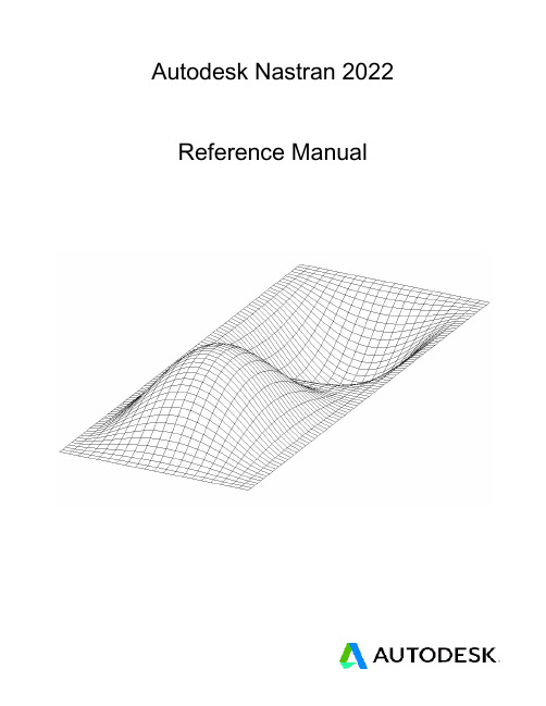
Autodesk Nastran 2022
Reference Manual
Nastran Solver Reference Manual
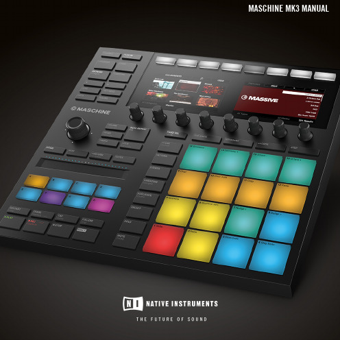
Native Instruments MASCHINE MK3 用户手册说明书
The information in this document is subject to change without notice and does not represent a commitment on the part of Native Instruments GmbH. The software described by this docu-ment is subject to a License Agreement and may not be copied to other media. No part of this publication may be copied, reproduced or otherwise transmitted or recorded, for any purpose, without prior written permission by Native Instruments GmbH, hereinafter referred to as Native Instruments.“Native Instruments”, “NI” and associated logos are (registered) trademarks of Native Instru-ments GmbH.ASIO, VST, HALion and Cubase are registered trademarks of Steinberg Media Technologies GmbH.All other product and company names are trademarks™ or registered® trademarks of their re-spective holders. Use of them does not imply any affiliation with or endorsement by them.Document authored by: David Gover and Nico Sidi.Software version: 2.8 (02/2019)Hardware version: MASCHINE MK3Special thanks to the Beta Test Team, who were invaluable not just in tracking down bugs, but in making this a better product.NATIVE INSTRUMENTS GmbH Schlesische Str. 29-30D-10997 Berlin Germanywww.native-instruments.de NATIVE INSTRUMENTS North America, Inc. 6725 Sunset Boulevard5th FloorLos Angeles, CA 90028USANATIVE INSTRUMENTS K.K.YO Building 3FJingumae 6-7-15, Shibuya-ku, Tokyo 150-0001Japanwww.native-instruments.co.jp NATIVE INSTRUMENTS UK Limited 18 Phipp StreetLondon EC2A 4NUUKNATIVE INSTRUMENTS FRANCE SARL 113 Rue Saint-Maur75011 ParisFrance SHENZHEN NATIVE INSTRUMENTS COMPANY Limited 5F, Shenzhen Zimao Center111 Taizi Road, Nanshan District, Shenzhen, GuangdongChina© NATIVE INSTRUMENTS GmbH, 2019. All rights reserved.Table of Contents1Welcome to MASCHINE (25)1.1MASCHINE Documentation (26)1.2Document Conventions (27)1.3New Features in MASCHINE 2.8 (29)1.4New Features in MASCHINE 2.7.10 (31)1.5New Features in MASCHINE 2.7.8 (31)1.6New Features in MASCHINE 2.7.7 (32)1.7New Features in MASCHINE 2.7.4 (33)1.8New Features in MASCHINE 2.7.3 (36)2Quick Reference (38)2.1Using Your Controller (38)2.1.1Controller Modes and Mode Pinning (38)2.1.2Controlling the Software Views from Your Controller (40)2.2MASCHINE Project Overview (43)2.2.1Sound Content (44)2.2.2Arrangement (45)2.3MASCHINE Hardware Overview (48)2.3.1MASCHINE Hardware Overview (48)2.3.1.1Control Section (50)2.3.1.2Edit Section (53)2.3.1.3Performance Section (54)2.3.1.4Group Section (56)2.3.1.5Transport Section (56)2.3.1.6Pad Section (58)2.3.1.7Rear Panel (63)2.4MASCHINE Software Overview (65)2.4.1Header (66)2.4.2Browser (68)2.4.3Arranger (70)2.4.4Control Area (73)2.4.5Pattern Editor (74)3Basic Concepts (76)3.1Important Names and Concepts (76)3.2Adjusting the MASCHINE User Interface (79)3.2.1Adjusting the Size of the Interface (79)3.2.2Switching between Ideas View and Song View (80)3.2.3Showing/Hiding the Browser (81)3.2.4Showing/Hiding the Control Lane (81)3.3Common Operations (82)3.3.1Using the 4-Directional Push Encoder (82)3.3.2Pinning a Mode on the Controller (83)3.3.3Adjusting Volume, Swing, and Tempo (84)3.3.4Undo/Redo (87)3.3.5List Overlay for Selectors (89)3.3.6Zoom and Scroll Overlays (90)3.3.7Focusing on a Group or a Sound (91)3.3.8Switching Between the Master, Group, and Sound Level (96)3.3.9Navigating Channel Properties, Plug-ins, and Parameter Pages in the Control Area.973.3.9.1Extended Navigate Mode on Your Controller (102)3.3.10Navigating the Software Using the Controller (105)3.3.11Using Two or More Hardware Controllers (106)3.3.12Touch Auto-Write Option (108)3.4Native Kontrol Standard (110)3.5Stand-Alone and Plug-in Mode (111)3.5.1Differences between Stand-Alone and Plug-in Mode (112)3.5.2Switching Instances (113)3.5.3Controlling Various Instances with Different Controllers (114)3.6Host Integration (114)3.6.1Setting up Host Integration (115)3.6.1.1Setting up Ableton Live (macOS) (115)3.6.1.2Setting up Ableton Live (Windows) (116)3.6.1.3Setting up Apple Logic Pro X (116)3.6.2Integration with Ableton Live (117)3.6.3Integration with Apple Logic Pro X (119)3.7Preferences (120)3.7.1Preferences – General Page (121)3.7.2Preferences – Audio Page (126)3.7.3Preferences – MIDI Page (130)3.7.4Preferences – Default Page (133)3.7.5Preferences – Library Page (137)3.7.6Preferences – Plug-ins Page (145)3.7.7Preferences – Hardware Page (150)3.7.8Preferences – Colors Page (154)3.8Integrating MASCHINE into a MIDI Setup (156)3.8.1Connecting External MIDI Equipment (156)3.8.2Sync to External MIDI Clock (157)3.8.3Send MIDI Clock (158)3.9Syncing MASCHINE using Ableton Link (159)3.9.1Connecting to a Network (159)3.9.2Joining and Leaving a Link Session (159)3.10Using a Pedal with the MASCHINE Controller (160)3.11File Management on the MASCHINE Controller (161)4Browser (163)4.1Browser Basics (163)4.1.1The MASCHINE Library (163)4.1.2Browsing the Library vs. Browsing Your Hard Disks (164)4.2Searching and Loading Files from the Library (165)4.2.1Overview of the Library Pane (165)4.2.2Selecting or Loading a Product and Selecting a Bank from the Browser (170)4.2.2.1[MK3] Browsing by Product Category Using the Controller (174)4.2.2.2[MK3] Browsing by Product Vendor Using the Controller (174)4.2.3Selecting a Product Category, a Product, a Bank, and a Sub-Bank (175)4.2.3.1Selecting a Product Category, a Product, a Bank, and a Sub-Bank on theController (179)4.2.4Selecting a File Type (180)4.2.5Choosing Between Factory and User Content (181)4.2.6Selecting Type and Character Tags (182)4.2.7List and Tag Overlays in the Browser (186)4.2.8Performing a Text Search (188)4.2.9Loading a File from the Result List (188)4.3Additional Browsing Tools (193)4.3.1Loading the Selected Files Automatically (193)4.3.2Auditioning Instrument Presets (195)4.3.3Auditioning Samples (196)4.3.4Loading Groups with Patterns (197)4.3.5Loading Groups with Routing (198)4.3.6Displaying File Information (198)4.4Using Favorites in the Browser (199)4.5Editing the Files’ Tags and Properties (203)4.5.1Attribute Editor Basics (203)4.5.2The Bank Page (205)4.5.3The Types and Characters Pages (205)4.5.4The Properties Page (208)4.6Loading and Importing Files from Your File System (209)4.6.1Overview of the FILES Pane (209)4.6.2Using Favorites (211)4.6.3Using the Location Bar (212)4.6.4Navigating to Recent Locations (213)4.6.5Using the Result List (214)4.6.6Importing Files to the MASCHINE Library (217)4.7Locating Missing Samples (219)4.8Using Quick Browse (221)5Managing Sounds, Groups, and Your Project (225)5.1Overview of the Sounds, Groups, and Master (225)5.1.1The Sound, Group, and Master Channels (226)5.1.2Similarities and Differences in Handling Sounds and Groups (227)5.1.3Selecting Multiple Sounds or Groups (228)5.2Managing Sounds (233)5.2.1Loading Sounds (235)5.2.2Pre-listening to Sounds (236)5.2.3Renaming Sound Slots (237)5.2.4Changing the Sound’s Color (237)5.2.5Saving Sounds (239)5.2.6Copying and Pasting Sounds (241)5.2.7Moving Sounds (244)5.2.8Resetting Sound Slots (245)5.3Managing Groups (247)5.3.1Creating Groups (248)5.3.2Loading Groups (249)5.3.3Renaming Groups (251)5.3.4Changing the Group’s Color (251)5.3.5Saving Groups (253)5.3.6Copying and Pasting Groups (255)5.3.7Reordering Groups (258)5.3.8Deleting Groups (259)5.4Exporting MASCHINE Objects and Audio (260)5.4.1Saving a Group with its Samples (261)5.4.2Saving a Project with its Samples (262)5.4.3Exporting Audio (264)5.5Importing Third-Party File Formats (270)5.5.1Loading REX Files into Sound Slots (270)5.5.2Importing MPC Programs to Groups (271)6Playing on the Controller (275)6.1Adjusting the Pads (275)6.1.1The Pad View in the Software (275)6.1.2Choosing a Pad Input Mode (277)6.1.3Adjusting the Base Key (280)6.1.4Using Choke Groups (282)6.1.5Using Link Groups (284)6.2Adjusting the Key, Choke, and Link Parameters for Multiple Sounds (286)6.3Playing Tools (287)6.3.1Mute and Solo (288)6.3.2Choke All Notes (292)6.3.3Groove (293)6.3.4Level, Tempo, Tune, and Groove Shortcuts on Your Controller (295)6.3.5Tap Tempo (299)6.4Performance Features (300)6.4.1Overview of the Perform Features (300)6.4.2Selecting a Scale and Creating Chords (303)6.4.3Scale and Chord Parameters (303)6.4.4Creating Arpeggios and Repeated Notes (316)6.4.5Swing on Note Repeat / Arp Output (321)6.5Using Lock Snapshots (322)6.5.1Creating a Lock Snapshot (322)6.5.2Using Extended Lock (323)6.5.3Updating a Lock Snapshot (323)6.5.4Recalling a Lock Snapshot (324)6.5.5Morphing Between Lock Snapshots (324)6.5.6Deleting a Lock Snapshot (325)6.5.7Triggering Lock Snapshots via MIDI (326)6.6Using the Smart Strip (327)6.6.1Pitch Mode (328)6.6.2Modulation Mode (328)6.6.3Perform Mode (328)6.6.4Notes Mode (329)7Working with Plug-ins (330)7.1Plug-in Overview (330)7.1.1Plug-in Basics (330)7.1.2First Plug-in Slot of Sounds: Choosing the Sound’s Role (334)7.1.3Loading, Removing, and Replacing a Plug-in (335)7.1.3.1Browser Plug-in Slot Selection (341)7.1.4Adjusting the Plug-in Parameters (344)7.1.5Bypassing Plug-in Slots (344)7.1.6Using Side-Chain (346)7.1.7Moving Plug-ins (346)7.1.8Alternative: the Plug-in Strip (348)7.1.9Saving and Recalling Plug-in Presets (348)7.1.9.1Saving Plug-in Presets (349)7.1.9.2Recalling Plug-in Presets (350)7.1.9.3Removing a Default Plug-in Preset (351)7.2The Sampler Plug-in (352)7.2.1Page 1: Voice Settings / Engine (354)7.2.2Page 2: Pitch / Envelope (356)7.2.3Page 3: FX / Filter (359)7.2.4Page 4: Modulation (361)7.2.5Page 5: LFO (363)7.2.6Page 6: Velocity / Modwheel (365)7.3Using Native Instruments and External Plug-ins (367)7.3.1Opening/Closing Plug-in Windows (367)7.3.2Using the VST/AU Plug-in Parameters (370)7.3.3Setting Up Your Own Parameter Pages (371)7.3.4Using VST/AU Plug-in Presets (376)7.3.5Multiple-Output Plug-ins and Multitimbral Plug-ins (378)8Using the Audio Plug-in (380)8.1Loading a Loop into the Audio Plug-in (384)8.2Editing Audio in the Audio Plug-in (385)8.3Using Loop Mode (386)8.4Using Gate Mode (388)9Using the Drumsynths (390)9.1Drumsynths – General Handling (391)9.1.1Engines: Many Different Drums per Drumsynth (391)9.1.2Common Parameter Organization (391)9.1.3Shared Parameters (394)9.1.4Various Velocity Responses (394)9.1.5Pitch Range, Tuning, and MIDI Notes (394)9.2The Kicks (395)9.2.1Kick – Sub (397)9.2.2Kick – Tronic (399)9.2.3Kick – Dusty (402)9.2.4Kick – Grit (403)9.2.5Kick – Rasper (406)9.2.6Kick – Snappy (407)9.2.7Kick – Bold (409)9.2.8Kick – Maple (411)9.2.9Kick – Push (412)9.3The Snares (414)9.3.1Snare – Volt (416)9.3.2Snare – Bit (418)9.3.3Snare – Pow (420)9.3.4Snare – Sharp (421)9.3.5Snare – Airy (423)9.3.6Snare – Vintage (425)9.3.7Snare – Chrome (427)9.3.8Snare – Iron (429)9.3.9Snare – Clap (431)9.3.10Snare – Breaker (433)9.4The Hi-hats (435)9.4.1Hi-hat – Silver (436)9.4.2Hi-hat – Circuit (438)9.4.3Hi-hat – Memory (440)9.4.4Hi-hat – Hybrid (442)9.4.5Creating a Pattern with Closed and Open Hi-hats (444)9.5The Toms (445)9.5.1Tom – Tronic (447)9.5.2Tom – Fractal (449)9.5.3Tom – Floor (453)9.5.4Tom – High (455)9.6The Percussions (456)9.6.1Percussion – Fractal (458)9.6.2Percussion – Kettle (461)9.6.3Percussion – Shaker (463)9.7The Cymbals (467)9.7.1Cymbal – Crash (469)9.7.2Cymbal – Ride (471)10Using the Bass Synth (474)10.1Bass Synth – General Handling (475)10.1.1Parameter Organization (475)10.1.2Bass Synth Parameters (477)11Working with Patterns (479)11.1Pattern Basics (479)11.1.1Pattern Editor Overview (480)11.1.2Navigating the Event Area (486)11.1.3Following the Playback Position in the Pattern (488)11.1.4Jumping to Another Playback Position in the Pattern (489)11.1.5Group View and Keyboard View (491)11.1.6Adjusting the Arrange Grid and the Pattern Length (493)11.1.7Adjusting the Step Grid and the Nudge Grid (497)11.2Recording Patterns in Real Time (501)11.2.1Recording Your Patterns Live (501)11.2.2The Record Prepare Mode (504)11.2.3Using the Metronome (505)11.2.4Recording with Count-in (506)11.2.5Quantizing while Recording (508)11.3Recording Patterns with the Step Sequencer (508)11.3.1Step Mode Basics (508)11.3.2Editing Events in Step Mode (511)11.3.3Recording Modulation in Step Mode (513)11.4Editing Events (514)11.4.1Editing Events with the Mouse: an Overview (514)11.4.2Creating Events/Notes (517)11.4.3Selecting Events/Notes (518)11.4.4Editing Selected Events/Notes (526)11.4.5Deleting Events/Notes (532)11.4.6Cut, Copy, and Paste Events/Notes (535)11.4.7Quantizing Events/Notes (538)11.4.8Quantization While Playing (540)11.4.9Doubling a Pattern (541)11.4.10Adding Variation to Patterns (541)11.5Recording and Editing Modulation (546)11.5.1Which Parameters Are Modulatable? (547)11.5.2Recording Modulation (548)11.5.3Creating and Editing Modulation in the Control Lane (550)11.6Creating MIDI Tracks from Scratch in MASCHINE (555)11.7Managing Patterns (557)11.7.1The Pattern Manager and Pattern Mode (558)11.7.2Selecting Patterns and Pattern Banks (560)11.7.3Creating Patterns (563)11.7.4Deleting Patterns (565)11.7.5Creating and Deleting Pattern Banks (566)11.7.6Naming Patterns (568)11.7.7Changing the Pattern’s Color (570)11.7.8Duplicating, Copying, and Pasting Patterns (571)11.7.9Moving Patterns (574)11.7.10Adjusting Pattern Length in Fine Increments (575)11.8Importing/Exporting Audio and MIDI to/from Patterns (576)11.8.1Exporting Audio from Patterns (576)11.8.2Exporting MIDI from Patterns (577)11.8.3Importing MIDI to Patterns (580)12Audio Routing, Remote Control, and Macro Controls (589)12.1Audio Routing in MASCHINE (590)12.1.1Sending External Audio to Sounds (591)12.1.2Configuring the Main Output of Sounds and Groups (596)12.1.3Setting Up Auxiliary Outputs for Sounds and Groups (601)12.1.4Configuring the Master and Cue Outputs of MASCHINE (605)12.1.5Mono Audio Inputs (610)12.1.5.1Configuring External Inputs for Sounds in Mix View (611)12.2Using MIDI Control and Host Automation (614)12.2.1Triggering Sounds via MIDI Notes (615)12.2.2Triggering Scenes via MIDI (622)12.2.3Controlling Parameters via MIDI and Host Automation (623)12.2.4Selecting VST/AU Plug-in Presets via MIDI Program Change (631)12.2.5Sending MIDI from Sounds (632)12.3Creating Custom Sets of Parameters with the Macro Controls (636)12.3.1Macro Control Overview (637)12.3.2Assigning Macro Controls Using the Software (638)12.3.3Assigning Macro Controls Using the Controller (644)13Controlling Your Mix (646)13.1Mix View Basics (646)13.1.1Switching between Arrange View and Mix View (646)13.1.2Mix View Elements (647)13.2The Mixer (649)13.2.1Displaying Groups vs. Displaying Sounds (650)13.2.2Adjusting the Mixer Layout (652)13.2.3Selecting Channel Strips (653)13.2.4Managing Your Channels in the Mixer (654)13.2.5Adjusting Settings in the Channel Strips (656)13.2.6Using the Cue Bus (660)13.3The Plug-in Chain (662)13.4The Plug-in Strip (663)13.4.1The Plug-in Header (665)13.4.2Panels for Drumsynths and Internal Effects (667)13.4.3Panel for the Sampler (668)13.4.4Custom Panels for Native Instruments Plug-ins (671)13.4.5Undocking a Plug-in Panel (Native Instruments and External Plug-ins Only) (675)13.5Controlling Your Mix from the Controller (677)13.5.1Navigating Your Channels in Mix Mode (678)13.5.2Adjusting the Level and Pan in Mix Mode (679)13.5.3Mute and Solo in Mix Mode (680)13.5.4Plug-in Icons in Mix Mode (680)14Using Effects (681)14.1Applying Effects to a Sound, a Group or the Master (681)14.1.1Adding an Effect (681)14.1.2Other Operations on Effects (690)14.1.3Using the Side-Chain Input (692)14.2Applying Effects to External Audio (695)14.2.1Step 1: Configure MASCHINE Audio Inputs (695)14.2.2Step 2: Set up a Sound to Receive the External Input (698)14.2.3Step 3: Load an Effect to Process an Input (700)14.3Creating a Send Effect (701)14.3.1Step 1: Set Up a Sound or Group as Send Effect (702)14.3.2Step 2: Route Audio to the Send Effect (706)14.3.3 A Few Notes on Send Effects (708)14.4Creating Multi-Effects (709)15Effect Reference (712)15.1Dynamics (713)15.1.1Compressor (713)15.1.2Gate (717)15.1.3Transient Master (721)15.1.4Limiter (723)15.1.5Maximizer (727)15.2Filtering Effects (730)15.2.1EQ (730)15.2.2Filter (733)15.2.3Cabinet (737)15.3Modulation Effects (738)15.3.1Chorus (738)15.3.2Flanger (740)15.3.3FM (742)15.3.4Freq Shifter (743)15.3.5Phaser (745)15.4Spatial and Reverb Effects (747)15.4.1Ice (747)15.4.2Metaverb (749)15.4.3Reflex (750)15.4.4Reverb (Legacy) (752)15.4.5Reverb (754)15.4.5.1Reverb Room (754)15.4.5.2Reverb Hall (757)15.4.5.3Plate Reverb (760)15.5Delays (762)15.5.1Beat Delay (762)15.5.2Grain Delay (765)15.5.3Grain Stretch (767)15.5.4Resochord (769)15.6Distortion Effects (771)15.6.1Distortion (771)15.6.2Lofi (774)15.6.3Saturator (775)15.7Perform FX (779)15.7.1Filter (780)15.7.2Flanger (782)15.7.3Burst Echo (785)15.7.4Reso Echo (787)15.7.5Ring (790)15.7.6Stutter (792)15.7.7Tremolo (795)15.7.8Scratcher (798)16Working with the Arranger (801)16.1Arranger Basics (801)16.1.1Navigating Song View (804)16.1.2Following the Playback Position in Your Project (806)16.1.3Performing with Scenes and Sections using the Pads (807)16.2Using Ideas View (811)16.2.1Scene Overview (811)16.2.2Creating Scenes (813)16.2.3Assigning and Removing Patterns (813)16.2.4Selecting Scenes (817)16.2.5Deleting Scenes (818)16.2.6Creating and Deleting Scene Banks (820)16.2.7Clearing Scenes (820)16.2.8Duplicating Scenes (821)16.2.9Reordering Scenes (822)16.2.10Making Scenes Unique (824)16.2.11Appending Scenes to Arrangement (825)16.2.12Naming Scenes (826)16.2.13Changing the Color of a Scene (827)16.3Using Song View (828)16.3.1Section Management Overview (828)16.3.2Creating Sections (833)16.3.3Assigning a Scene to a Section (834)16.3.4Selecting Sections and Section Banks (835)16.3.5Reorganizing Sections (839)16.3.6Adjusting the Length of a Section (840)16.3.6.1Adjusting the Length of a Section Using the Software (841)16.3.6.2Adjusting the Length of a Section Using the Controller (843)16.3.7Clearing a Pattern in Song View (843)16.3.8Duplicating Sections (844)16.3.8.1Making Sections Unique (845)16.3.9Removing Sections (846)16.3.10Renaming Scenes (848)16.3.11Clearing Sections (849)16.3.12Creating and Deleting Section Banks (850)16.3.13Working with Patterns in Song view (850)16.3.13.1Creating a Pattern in Song View (850)16.3.13.2Selecting a Pattern in Song View (850)16.3.13.3Clearing a Pattern in Song View (851)16.3.13.4Renaming a Pattern in Song View (851)16.3.13.5Coloring a Pattern in Song View (851)16.3.13.6Removing a Pattern in Song View (852)16.3.13.7Duplicating a Pattern in Song View (852)16.3.14Enabling Auto Length (852)16.3.15Looping (853)16.3.15.1Setting the Loop Range in the Software (854)16.4Playing with Sections (855)16.4.1Jumping to another Playback Position in Your Project (855)16.5Triggering Sections or Scenes via MIDI (856)16.6The Arrange Grid (858)16.7Quick Grid (860)17Sampling and Sample Mapping (862)17.1Opening the Sample Editor (862)17.2Recording Audio (863)17.2.1Opening the Record Page (863)17.2.2Selecting the Source and the Recording Mode (865)17.2.3Arming, Starting, and Stopping the Recording (868)17.2.5Using the Footswitch for Recording Audio (871)17.2.6Checking Your Recordings (872)17.2.7Location and Name of Your Recorded Samples (876)17.3Editing a Sample (876)17.3.1Using the Edit Page (877)17.3.2Audio Editing Functions (882)17.4Slicing a Sample (890)17.4.1Opening the Slice Page (891)17.4.2Adjusting the Slicing Settings (893)17.4.3Live Slicing (898)17.4.3.1Live Slicing Using the Controller (898)17.4.3.2Delete All Slices (899)17.4.4Manually Adjusting Your Slices (899)17.4.5Applying the Slicing (906)17.5Mapping Samples to Zones (912)17.5.1Opening the Zone Page (912)17.5.2Zone Page Overview (913)17.5.3Selecting and Managing Zones in the Zone List (915)17.5.4Selecting and Editing Zones in the Map View (920)17.5.5Editing Zones in the Sample View (924)17.5.6Adjusting the Zone Settings (927)17.5.7Adding Samples to the Sample Map (934)18Appendix: Tips for Playing Live (937)18.1Preparations (937)18.1.1Focus on the Hardware (937)18.1.2Customize the Pads of the Hardware (937)18.1.3Check Your CPU Power Before Playing (937)18.1.4Name and Color Your Groups, Patterns, Sounds and Scenes (938)18.1.5Consider Using a Limiter on Your Master (938)18.1.6Hook Up Your Other Gear and Sync It with MIDI Clock (938)18.1.7Improvise (938)18.2Basic Techniques (938)18.2.1Use Mute and Solo (938)18.2.2Use Scene Mode and Tweak the Loop Range (939)18.2.3Create Variations of Your Drum Patterns in the Step Sequencer (939)18.2.4Use Note Repeat (939)18.2.5Set Up Your Own Multi-effect Groups and Automate Them (939)18.3Special Tricks (940)18.3.1Changing Pattern Length for Variation (940)18.3.2Using Loops to Cycle Through Samples (940)18.3.3Using Loops to Cycle Through Samples (940)18.3.4Load Long Audio Files and Play with the Start Point (940)19Troubleshooting (941)19.1Knowledge Base (941)19.2Technical Support (941)19.3Registration Support (942)19.4User Forum (942)20Glossary (943)Index (951)1Welcome to MASCHINEThank you for buying MASCHINE!MASCHINE is a groove production studio that implements the familiar working style of classi-cal groove boxes along with the advantages of a computer based system. MASCHINE is ideal for making music live, as well as in the studio. It’s the hands-on aspect of a dedicated instru-ment, the MASCHINE hardware controller, united with the advanced editing features of the MASCHINE software.Creating beats is often not very intuitive with a computer, but using the MASCHINE hardware controller to do it makes it easy and fun. You can tap in freely with the pads or use Note Re-peat to jam along. Alternatively, build your beats using the step sequencer just as in classic drum machines.Patterns can be intuitively combined and rearranged on the fly to form larger ideas. You can try out several different versions of a song without ever having to stop the music.Since you can integrate it into any sequencer that supports VST, AU, or AAX plug-ins, you can reap the benefits in almost any software setup, or use it as a stand-alone application. You can sample your own material, slice loops and rearrange them easily.However, MASCHINE is a lot more than an ordinary groovebox or sampler: it comes with an inspiring 7-gigabyte library, and a sophisticated, yet easy to use tag-based Browser to give you instant access to the sounds you are looking for.What’s more, MASCHINE provides lots of options for manipulating your sounds via internal ef-fects and other sound-shaping possibilities. You can also control external MIDI hardware and 3rd-party software with the MASCHINE hardware controller, while customizing the functions of the pads, knobs and buttons according to your needs utilizing the included Controller Editor application. We hope you enjoy this fantastic instrument as much as we do. Now let’s get go-ing!—The MASCHINE team at Native Instruments.MASCHINE Documentation1.1MASCHINE DocumentationNative Instruments provide many information sources regarding MASCHINE. The main docu-ments should be read in the following sequence:1.MASCHINE Getting Started: This document provides a practical approach to MASCHINE viaa set of tutorials covering easy and more advanced tasks in order to help you familiarizeyourself with MASCHINE.2.MASCHINE Manual (this document): The MASCHINE Manual provides you with a compre-hensive description of all MASCHINE software and hardware features.Additional documentation sources provide you with details on more specific topics:▪Controller Editor Manual: Besides using your MASCHINE hardware controller together withits dedicated MASCHINE software, you can also use it as a powerful and highly versatileMIDI controller to pilot any other MIDI-capable application or device. This is made possibleby the Controller Editor software, an application that allows you to precisely define all MIDIassignments for your MASCHINE controller. The Controller Editor was installed during theMASCHINE installation procedure. For more information on this, please refer to the Con-troller Editor Manual available as a PDF file via the Help menu of Controller Editor.▪Online Support Videos: You can find a number of support videos on The Official Native In-struments Support Channel under the following URL: https:///NIsupport-EN. We recommend that you follow along with these instructions while the respective ap-plication is running on your computer.Other Online Resources:If you are experiencing problems related to your Native Instruments product that the supplied documentation does not cover, there are several ways of getting help:▪Knowledge Base▪User Forum▪Technical Support▪Registration SupportYou will find more information on these subjects in the chapter Troubleshooting.1.2Document ConventionsThis section introduces you to the signage and text highlighting used in this manual. This man-ual uses particular formatting to point out special facts and to warn you of potential issues. The icons introducing these notes let you see what kind of information is to be expected:This document uses particular formatting to point out special facts and to warn you of poten-tial issues. The icons introducing the following notes let you see what kind of information can be expected:Furthermore, the following formatting is used:▪Text appearing in (drop-down) menus (such as Open…, Save as… etc.) in the software and paths to locations on your hard disk or other storage devices is printed in italics.▪Text appearing elsewhere (labels of buttons, controls, text next to checkboxes etc.) in the software is printed in blue. Whenever you see this formatting applied, you will find the same text appearing somewhere on the screen.▪Text appearing on the displays of the controller is printed in light grey. Whenever you see this formatting applied, you will find the same text on a controller display.▪Text appearing on labels of the hardware controller is printed in orange. Whenever you see this formatting applied, you will find the same text on the controller.▪Important names and concepts are printed in bold.▪References to keys on your computer’s keyboard you’ll find put in square brackets (e.g.,“Press [Shift] + [Enter]”).►Single instructions are introduced by this play button type arrow.→Results of actions are introduced by this smaller arrow.Naming ConventionThroughout the documentation we will refer to MASCHINE controller (or just controller) as the hardware controller and MASCHINE software as the software installed on your computer.The term “effect” will sometimes be abbreviated as “FX” when referring to elements in the MA-SCHINE software and hardware. These terms have the same meaning.Button Combinations and Shortcuts on Your ControllerMost instructions will use the “+” sign to indicate buttons (or buttons and pads) that must be pressed simultaneously, starting with the button indicated first. E.g., an instruction such as:“Press SHIFT + PLAY”means:1.Press and hold SHIFT.2.While holding SHIFT, press PLAY and release it.3.Release SHIFT.Unlabeled Buttons on the ControllerThe buttons and knobs above and below the displays on your MASCHINE controller do not have labels.。
methodvalidationpostprocessor类 -回复

methodvalidationpostprocessor类-回复[methodValidationPostProcessor 类]:将测试结果用于后续处理的方法验证器1. 引言(100-200字)在软件开发的过程中,测试是至关重要的一环。
它帮助我们确保软件的质量和稳定性,并确保软件按照预期的方式运行。
然而,仅仅进行测试是不够的,我们还需要将测试结果用于后续处理。
methodValidationPostProcessor 类就是为此而设计的,它能够接收测试结果,并根据需要进行额外的处理操作。
2. methodValidationPostProcessor 类概述(200-400字)methodValidationPostProcessor 类是在测试过程中常用的一个工具。
它允许我们将测试结果传递给后续处理器,如日志记录器、报告生成器等等。
通过这些后续处理器,我们可以进一步分析和处理测试结果,以便更好地了解软件的性能和稳定性。
该类的使用非常灵活,它可以与各种测试框架和工具集成,以满足不同项目的需求。
methodValidationPostProcessor 类支持包括JUnit、TestNG 等在内的主流测试框架,并提供了丰富的API和配置选项。
3. methodValidationPostProcessor 类的功能(400-600字)methodValidationPostProcessor 类具有以下主要功能:3.1 集成测试框架methodValidationPostProcessor 类提供了与不同测试框架的集成能力。
它可以与JUnit、TestNG等主流测试框架协同工作,以便于在测试过程中收集和处理测试结果。
3.2 结果过滤和转换methodValidationPostProcessor 类允许我们根据需求对测试结果进行过滤和转换。
我们可以使用内置的规则引擎或自定义的逻辑来过滤出需要的结果,并将其转换成我们想要的格式。
示教器操作手册最终版
正则动量解题-概述说明以及解释
正则动量解题-概述说明以及解释1.引言1.1 概述正则动量解题是利用正则表达式与动量法相结合的一种解题方法。
正则表达式是一种用来描述字符串模式的工具,它具有强大的匹配和替换功能。
而动量法是一种通用的优化算法,采用移动平均的方式来调整搜索的方向和步长,能够有效地优化解题过程。
本文将首先介绍正则表达式的基本概念,包括字符匹配、分组、量词等,为读者提供必要的背景知识。
接着,文章将重点探讨动量法在解题中的应用。
动量法通过利用历史迭代的信息来调整搜索方向和步长,可以提高搜索的效率和准确性。
在解题中,我们可以利用动量法来优化正则表达式的匹配过程,从而更快速地找到所需的答案。
总结部分将对整篇文章进行归纳总结,总结正则动量解题的优势与不足之处,并探讨未来在该领域的发展前景。
通过本文的阅读,读者将对正则动量解题有一个全面的了解,能够在实际问题中灵活运用这种方法,提高解题的效率和准确性。
因此,本文的目的是通过介绍正则表达式的基本概念和动量法的应用,探讨正则动量解题的方法和优势,为读者提供一个全面的解题思路。
希望本文能够对读者在解决实际问题时提供一定的指导和帮助。
1.2文章结构文章结构部分的内容应该是对整篇文章的组织和章节安排进行介绍。
在这个部分,可以简要描述各个章节的内容和目的,以及它们之间的关系。
以下是对文章结构部分内容的一个示例:文章结构:本文共分为三个主要部分:引言、正文和结论。
引言部分将首先对本文的主题进行概述,包括讨论正则动量解题的背景和意义。
然后,文章将介绍本文的结构和各个章节的目的,为读者提供一个整体的框架。
正文部分包含两个章节:正则表达式的基本概念和动量法在解题中的应用。
在第一章节中,将对正则表达式的基本概念进行详细解释,包括正则表达式的语法和匹配原理。
第二章节将介绍动量法在解题中的应用,包括如何利用动量法解决常见的问题和优化解题过程。
结论部分将对全文进行总结,总结本文的主要观点和结论。
同时,还将展望正则动量解题的未来发展方向和可能的研究方向。
validation invocation of init method failed
validation invocation of init method failed "Validation invocation of init method failed"是一个常见的错误消息,通常在编程中与对象的初始化过程有关。
这个错误提示表明在对象的构造或初始化方法(如构造函数或初始化块)中发生了验证错误。
以下是一些可能导致该错误的常见原因和解决方法:
1.参数错误:初始化方法可能接受了不正确或无效的参数。
检查传递给初始化方法的参数是否符合预期的类型、范围或其他要求。
2.约束条件失败:初始化方法可能包含一些约束条件的逻辑,例如检查属性的值是否有效。
检查初始化方法中的逻辑,确保所有的约束条件都得到满足。
3.依赖问题:对象的初始化可能依赖于其他对象或资源的可用性。
检查是否正确地初始化了所需的依赖项。
4.异常处理:初始化方法中可能抛出了异常,但没有被正确地捕获或处理。
确保在初始化方法中处理了所有可能的异常情况。
5.类设计问题:对象的初始化逻辑可能存在问题,例如循环依赖、不正确的构造顺序等。
检查类的设计和构造方式,确保它们符合良好的编程实践。
要解决这个错误,你可以采取以下步骤:
1.仔细检查初始化方法的代码,特别是参数检查、约束条件和依赖项的初始化。
2.确保传递给初始化方法的参数是正确的,并符合预期的要求。
3.处理初始化方法中可能抛出的异常。
4.检查类的设计和构造方式,确保它们是合理和正确的。
missing values encountered in interpolated fields
missing values encountered in interpolated fields
"missing values encountered in interpolated fields" 是一个英文短语,直译为中文是“在插值字段中遇到缺失值”。
这句话通常出现在处理数据或进行数值计算时。
当某个字段或数据集中存在缺失值,而该值需要进行插值(interpolation)处理时,可能会遇到这样的问题。
简单来说,插值是一种数学方法,用于估算在给定数据点之间的未知值。
当存在缺失值时,插值算法可能无法准确地估算这些缺失值,从而导致问题。
为了解决这个问题,通常需要对数据进行预处理,例如填充缺失值或采用其他技术处理缺失数据,以便在执行插值操作时获得更准确的结果。
数据完整性和计算机管理GMP要求
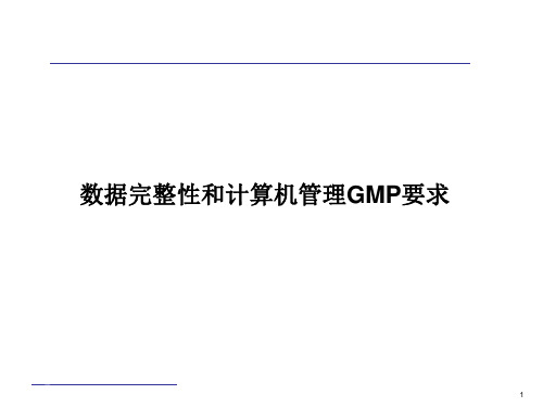
数据的生命周期:数据包括原始数据自初始生产和记录,到处理和 (包括转移或移植)、使用、数据保留、存档/恢复和重建的整个 生命阶段。
源(元)数据(Metadata): 指描述其他数据属性的数据,提供 语境和含义。一般来说,这些数据描述数据的结构、要素、内在 关系和其他数据特征。 它还允许数据追踪至个体。如产品A批号 267, 有2kg等;没有源数据,数据就没有意义。
20
数据管理基本要求
数据必须符合 ALCOA 原则: 1. A -- 可追踪至生产数据的人 2. L -- 清晰、在数据的整个生命周期内均可以获得,必要时能
永久保存 (如长达30年) 3. C -- 同步 4. O -- 原始(或真实复制): 可根据原始数据对数据生产的整
个活动进行重现 5. A --准确性
18
法规要求
1PPC控制器故障代码查询重要

Rexroth IndraControl VCP 20Industrial Hydraulics Electric Drivesand ControlsLinear Motion andAssembly Technologies PneumaticsServiceAutomationMobileHydraulicsRexroth VisualMotion 10 Multi-Axis Machine Control R911306327 Edition 01Troubleshooting GuideAbout this Documentation Rexroth VisualMotion 10 Troubleshooting Guide DOK-VISMOT-VM*-10VRS**-WA01-EN-PRexroth VisualMotion 10Multi-Axis Machine ControlTroubleshooting Guide DOK-VISMOT-VM*-10VRS**-WA01-EN-P Document Number, 120-2300-B323-01/ENPart of Box Set, 20-10V-EN (MN R911306370)This documentation describes …•the use of VisualMotion Toolkit for assitance in diagnostics •the proper steps for indentifing diagnostic faults • and the suggested remedies for clearing faults Description ReleaseDateNotes DOK-VISMOT-VM*-10VRS**-WA01-EN-P 08/2004Initial release© 2004 Bosch Rexroth AGCopying this document, giving it to others and the use or communicationof the contents thereof without express authority, are forbidden. Offendersare liable for the payment of damages. All rights are reserved in the eventof the grant of a patent or the registration of a utility model or design(DIN 34-1).The specified data is for product description purposes only and may notbe deemed to be guaranteed unless expressly confirmed in the contract.All rights are reserved with respect to the content of this documentationand the availability of the product.Bosch Rexroth AGBgm.-Dr.-Nebel-Str. 2 • D-97816 Lohr a. MainTel.: +49 (0)93 52/40-0 • Fax: +49 (0)93 52/40-48 85 • Telex: 68 94 21Bosch Rexroth Corporation • Electric Drives and Controls5150 Prairie Stone Parkway • Hoffman Estates, IL 60192 • USATel.: 847-645-3600 • Fax: 847-645-6201/Dept. ESG4 (DPJ)This document has been printed on chlorine-free bleached paper.Title Type of DocumentationDocument TypecodeInternal File Reference Purpose of Documentation Record of Revisions Copyright Validity Published byNoteRexroth VisualMotion 10 Troubleshooting Guide Table of Contents I Table of Contents1VisualMotion Tools for Diagnosing1-1 The Diagnostics Menu.............................................................................................................1-1System Diagnostics.................................................................................................................1-1Tasks Diagnostics...................................................................................................................1-3Drive Overview….....................................................................................................................1-42Monitoring and Diagnostics2-12.1System Diagnostics - Codes and Message...................................................................................2-1Parameters..............................................................................................................................2-2DriveTop..................................................................................................................................2-32.2Control Startup Messages.............................................................................................................2-4PPC Boot-Up Sequence..........................................................................................................2-4Control Firmware Sequence....................................................................................................2-42.3Status Messages (001-199)...........................................................................................................2-5001 Initializing System.............................................................................................................2-5002 Parameter Mode...............................................................................................................2-5003 Initializing Drives...............................................................................................................2-5004 System is Ready...............................................................................................................2-5005 Manual Mode....................................................................................................................2-5006 Automatic Mode: ABCD....................................................................................................2-5007 Program Running: ABCD.................................................................................................2-6008 Single-Stepping: ABCD....................................................................................................2-6009 Select Parameter Mode to Continue................................................................................2-6010 Breakpoint Reached: ABCD.............................................................................................2-6018 Please cycle power to continue........................................................................................2-6019 Executing User Initialization Task....................................................................................2-62.4Warning Messages (201-399).......................................................................................................2-7201 Invalid jog type or axis selected........................................................................................2-7202 Drive %d is not ready.......................................................................................................2-7203 Power Fail detected..........................................................................................................2-7204 Sercos ring was disconnected..........................................................................................2-8205 Parameter transfer warning in Task %c...........................................................................2-8207 Axis %d position limit reached..........................................................................................2-8208 Lost Fieldbus Connection.................................................................................................2-9209 Fieldbus Mapping Timeout...............................................................................................2-9210 File System Defrag: %d completed................................................................................2-10211 Program- & Data memory cleared..................................................................................2-10212 Option Card PLS Warning, see ext. diag.......................................................................2-10213 Sercos cycle time changed.............................................................................................2-11214 PCI Bus Cyclic Mapping Timeout...................................................................................2-11 DOK-VISMOT-VM*-10VRS**-WA01-EN-PII Table of Contents Rexroth VisualMotion 10 Troubleshooting Guide215 RECO I/O Failure, see ext. diag.....................................................................................2-11216 Control PLS %d warning, see ext. diag..........................................................................2-12217 PCI Bus Communication, see ext. diag..........................................................................2-12218 PCI Bus Register Mapping Timeout...............................................................................2-13219 PCI Bus Lifecounter Timeout.........................................................................................2-13220 Excessive deviation in PMG%d, see ext. diag...............................................................2-13221 Excessive Master Position Slip Deviation......................................................................2-13222 ELS Config. Warning, see ext. diag...............................................................................2-14223 PCI Bus reset occurred, cyclic data are invalid..............................................................2-14225 System booted................................................................................................................2-14226 RS485 Serial Communication Error (port X1%d)...........................................................2-15227 Control Over-temperature Warning................................................................................2-15228 Control - SYSTEM WARNING.......................................................................................2-152.5Shutdown Messages (400 - 599).................................................................................................2-16400 EMERGENCY STOP......................................................................................................2-16401 Sercos Controller Error: %02d........................................................................................2-16402 Sercos Config. Error: see ext. diag................................................................................2-16403 System Error see ext. diag.............................................................................................2-17405 Phase %d: Drive did not respond...................................................................................2-17407 Drive %d Phase 3 Switch Error......................................................................................2-17409 Sercos Disconnect Error.................................................................................................2-18411 Drive %d Phase 4 Switch Error......................................................................................2-18412 No drives were found on ring..........................................................................................2-18414 Parameters were lost......................................................................................................2-19415 Drive %d was not found..................................................................................................2-19416 Invalid Instruction at %04x..............................................................................................2-19417 SYSTEM ERROR: pSOS #%04x...................................................................................2-19418 No program is active.......................................................................................................2-20419 Invalid Program File: code = %d....................................................................................2-20420 Drive %d Shutdown Error...............................................................................................2-20421 User Program Stack Overflow........................................................................................2-20422 Parameter transfer error in Task %c..............................................................................2-21423 Unimplemented Instruction.............................................................................................2-21425 Instruction error: see Task %c diag................................................................................2-21426 Drive %d is not ready.....................................................................................................2-22427 Calc: invalid table index %d............................................................................................2-22428 Calc: division by zero......................................................................................................2-22429 Calc: too many operands................................................................................................2-22430 Calc: invalid operator......................................................................................................2-23431 Calc error: see Task %c diag.........................................................................................2-23432 Calc: too many nested expressions...............................................................................2-23433 Setup instruction outside of a task.................................................................................2-23434 Axis %d configured more than once...............................................................................2-23435 Axis %d is not assigned to a task...................................................................................2-24436 General Compiler Error: %04x.......................................................................................2-24438 Invalid Axis Selected: %d...............................................................................................2-24DOK-VISMOT-VM*-10VRS**-WA01-EN-PRexroth VisualMotion 10 Troubleshooting Guide Table of Contents III439 Axis %d: Invalid Motion Type.........................................................................................2-24440 I/O Transfer Error: see task diag....................................................................................2-25450 Event %d: invalid event type..........................................................................................2-25451 Invalid event number ‘%d’..............................................................................................2-25452 More than %d event timers armed.................................................................................2-25453 Homing param. transfer error: %d..................................................................................2-25454 Axis %d homing not complete........................................................................................2-26459 Axis %d target position out of bounds............................................................................2-26460 Invalid program %d from binary inputs...........................................................................2-26463 Ratio command: invalid ratio..........................................................................................2-26464 Can't activate while program running.............................................................................2-27465 Drive %d config. error, see ext. diag..............................................................................2-27467 Invalid ELS Master Option..............................................................................................2-27468 ELS adjustment out of bounds.......................................................................................2-27470 Axis %d velocity > maximum..........................................................................................2-28474 Drive %d cyclic data size too large.................................................................................2-28477 Axis D: probe edge not configured.................................................................................2-28478 Calc: operand out of range.............................................................................................2-28483 Parameter Init. Error: see Task %c diag........................................................................2-29484 Control SYSTEM ERROR..............................................................................................2-29486 Sercos Device %d is not a drive.....................................................................................2-29487 CAM %d is invalid or not stored.....................................................................................2-29488 CAM Error: See Task %c diag........................................................................................2-30489 More than %d CAM axes selected.................................................................................2-30490 System Memory Allocation Error....................................................................................2-30492 Programs were lost, see ext. diag..................................................................................2-30496 Can't execute this instruction from an event..................................................................2-31497 Limit switch config. error, see ext. diag.........................................................................2-31498 Drive %d Shutdown Warning..........................................................................................2-32499 Axis number %d not supported in this version...............................................................2-32500 Axis %d is not referenced...............................................................................................2-32501 Drive %d comm. error, see ext. diag..............................................................................2-33502 ELS and cams not supported in this version..................................................................2-33504 Communication Timeout.................................................................................................2-33505 Axis %d is not configured...............................................................................................2-33508 User Watchdog Timeout.................................................................................................2-33509 Control System Timing Error (%d).................................................................................2-34515 PLC Communications Error............................................................................................2-34516 More than %d registration functions enabled.................................................................2-34519 Lost Fieldbus/PLC Connection.......................................................................................2-35520 Fieldbus Mapping Timeout.............................................................................................2-35521 Invalid Virtual Master ID: %d..........................................................................................2-36522 Invalid ELS Master ID: %d..............................................................................................2-36523 IFS status, facility = 0x%x..............................................................................................2-36524 Hardware Watchdog timeout..........................................................................................2-36525 I/O Configuration error, see ext. diag.............................................................................2-36 DOK-VISMOT-VM*-10VRS**-WA01-EN-PIV Table of Contents Rexroth VisualMotion 10 Troubleshooting Guide526 Sercos Multiplex Channel Config, see ext. diag.............................................................2-37527 Control Initialization Error, see ext. diag.........................................................................2-38528 System Event %d Occurred...........................................................................................2-38529 Invalid ELS Group ID: %d...............................................................................................2-38530 CAM %d is active, can't overwrite..................................................................................2-39531 Invalid variable for Fieldbus/PCI Bus Mapping...............................................................2-39532 Power fail brown out condition detected.........................................................................2-39533 Multiple instances of index CAM: %d found...................................................................2-39534 Hardware Version Not Supported..................................................................................2-40539 Invalid Parameter Number..............................................................................................2-40540 Option Card PLS error....................................................................................................2-40541 Link Ring Error, see ext. diag.........................................................................................2-41542 PLC Cyclic Mapping Timeout.........................................................................................2-42543 PCI Bus Runtime Error...................................................................................................2-42544 RECO I/O Failure, see ext. diag.....................................................................................2-42545 Invalid Coordinated Articulation Function ID: %d...........................................................2-43546 Multiple Instance of Coordinated Articulation Function with ID: %d...............................2-43547 Task %c Coordinated Articulation Error, see ext. diag...................................................2-43548 Invalid Kinematic Number: %d.......................................................................................2-43549 Fieldbus Initialization Error.............................................................................................2-43550 User Initialization Task Timeout.....................................................................................2-44551 Master Slip Config. Error, see ext. diag..........................................................................2-44552 Excessive Master Position Slip Deviation......................................................................2-44553 Invalid Parameter Detected, see C-0-2002....................................................................2-44554 Excessive Deviation in PMG%d, see ext. diag...............................................................2-45555 PCI Bus Register Mapping Timeout...............................................................................2-45556 PCI Bus Lifecounter Timeout.........................................................................................2-45557 PMG%d Maximum allowed deviation window is Zero....................................................2-45558 PMG%d Only 1 axis parameterized...............................................................................2-46559 PMG%d Number of offsets does not match number of Axis..........................................2-46560 PMG%d Max. allowed dev. window is larger than 25% of Modulo................................2-46561 PMG%d Offset is larger than Modulo.............................................................................2-46562 PMG%d Parameterized Axis is not in system................................................................2-46563 Invalid Task Specified, Must be A-D..............................................................................2-46564 PMG%d Invalid configuration, see ext. diag...................................................................2-46565 Axis %d: Configuration error, see ext. diag....................................................................2-47566 Filter sample rate and cutoff frequency mismatch.........................................................2-47567 ELS Config. Error, see ext. diag.....................................................................................2-47568 Axis %d: Assigned Task is Not Defined.........................................................................2-48570 ELS Max. Vel. Exceeded, see ext. diag.........................................................................2-48571 No Program Found.........................................................................................................2-49572 PCI Bus reset occurred, cyclic data is invalid.................................................................2-49573 CAM %d is being built....................................................................................................2-49575 ELS Master for ELS Group %d is invalid........................................................................2-49576 Event for input I%d is already armed, cannot arm again...............................................2-50577 Restored non volatile memory from compact flash........................................................2-50DOK-VISMOT-VM*-10VRS**-WA01-EN-PRexroth VisualMotion 10 Troubleshooting Guide Table of Contents V578 Virtual Master %d Exceeded Its Max. Vel., see ext. diag...............................................2-50579 Group %d Exceeded Its Jog Velocity, see ext. diag......................................................2-51580 pROBE Error Occurred in Task:0x%04X.......................................................................2-51581 Probe Function for Axis # is locked by the PLC.............................................................2-51582 Integrated PLC: PLC Stopped in Operation Mode.........................................................2-51583 Integrated PLC: Internal System Error...........................................................................2-51584 ELS System Master %d is invalid, see ext. diag............................................................2-51585 Drive %d separate deceleration not supported..............................................................2-52586 Master Encoder Card Error, see ext diag.......................................................................2-522.6Integrated PLC Status Messages................................................................................................2-536001 Integrated PLC: Running..............................................................................................2-536002 Integrated PLC: Stopped..............................................................................................2-536002 Integrated PLC: Stopped at Breakpoint........................................................................2-532.7Integrated PLC Error Codes........................................................................................................2-530016 Integrated PLC: Software Watchdog Error...................................................................2-530019 Integrated PLC: Program Checksum Error..................................................................2-530020 Integrated PLC: Fieldbus Master Error.........................................................................2-540021 Integrated PLC: I/O Update Error.................................................................................2-542000 Integrated PLC: Internal SIS System Error..................................................................2-542001 Integrated PLC: Internal Acyclic Access Error.............................................................2-542002 Integrated PLC: Internal Acyclic Memory Error............................................................2-542003 Integrated PLC: PLC Configuration Error.....................................................................2-552004 Integrated PLC: File Access Error................................................................................2-552005 Integrated PLC: Internal Fatal Task Error....................................................................2-556011 Integrated PLC: PLC Program Stopped in Operation Mode........................................2-556012 Integrated PLC: General Error.....................................................................................2-552.8Communication Error Codes and Messages...............................................................................2-56!01 Sercos Error Code # xxxx...............................................................................................2-56!02 Invalid Parameter Number..............................................................................................2-57!03 Data is Read Only...........................................................................................................2-57!04 Write Protected in this mode/phase...............................................................................2-57!05 Greater than maximum value.........................................................................................2-57!06 Less than minimum value...............................................................................................2-57!07 Data is Invalid.................................................................................................................2-57!08 Drive was not found........................................................................................................2-57!09 Drive not ready for communication.................................................................................2-57!10 Drive is not responding...................................................................................................2-57!11 Service channel is not open...........................................................................................2-57!12 Invalid Command Class..................................................................................................2-57!13 Checksum Error: xx (xx= checksum that control calculated).........................................2-58!14 Invalid Command Subclass............................................................................................2-58!15 Invalid Parameter Set.....................................................................................................2-58!16 List already in progress..................................................................................................2-58!17 Invalid Sequence Number..............................................................................................2-58!18 List has not started.........................................................................................................2-58!19 List is finished.................................................................................................................2-58 DOK-VISMOT-VM*-10VRS**-WA01-EN-P。
热值仪中文说明
List of Illustrations------------------------------------------------------------- v
Chapter 1-------------------------------------------------------------------------- 1
符号
文件符号定义
标签
说明
WARNING
包括条件、惯例和步骤必须谨慎执行, 以防人员伤害和设备损坏。
CAUTION
包括条件、惯例和步骤必须谨慎执行, 以防人员伤害和设备损坏
CAUTION
电击或高温部分危险,如不采取适当的 警告,可导致人员伤害。
CAUTION
静电感应元件,要求正确地触摸,以防 损坏。
Flo-Cal 用户手册
ii 索引
Chapter 4 --------------------------------------------------------------------------17
Installation ....................................................................................................... 17 System Mounting .............................................................................................. 17 Unpacking and Inspection .................................................................... 17 Wall Mount Preparation and Procedure ............................................... 18 Free Standing Mount Instructions ........................................................ 20 Electrical Installation......................................................................................... 21 Gas & Air Supply Installation ........................................................................... 22
SIMATIC Energy Manager PRO V7.2 - Operation Operat
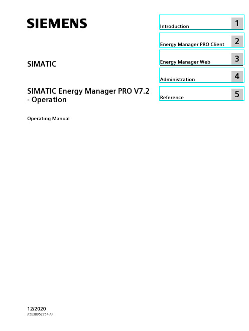
2 Energy Manager PRO Client................................................................................................................. 19
2.1 2.1.1 2.1.2 2.1.3 2.1.4 2.1.5 2.1.5.1 2.1.5.2 2.1.6
Basics ................................................................................................................................ 19 Start Energy Manager ........................................................................................................ 19 Client as navigation tool..................................................................................................... 23 Basic configuration ............................................................................................................ 25 Search for object................................................................................................................ 31 Quicklinks.......................................................................................................................... 33 Create Quicklinks ............................................................................................................... 33 Editing Quicklinks .............................................................................................................. 35 Help .................................................................................................................................. 38
idefixpack for delphi 2009 -回复
idefixpack for delphi 2009 -回复"idefixpack for Delphi 2009" is a comprehensive and powerful tool that enhances the functionality of Delphi 2009, a popular integrated development environment (IDE) for Object Pascal. In this article, we will explore the various features and benefits of idefixpack and provide step-by-step instructions on how to install and utilize it effectively.Introduction to idefixpack for Delphi 2009:idefixpack is an open-source tool designed to optimize and improve the performance of Delphi applications. It helps developers identify and resolve potential issues, such as unused code, bloated binaries, and performance bottlenecks. With its extensive range of features, idefixpack enables developers to write cleaner, more efficient, and faster applications.Installing idefixpack:Before we delve into the tool's functionalities, let's first understand how it can be installed in Delphi 2009. Follow these steps to get started:1. Download the latest version of idefixpack from the officialwebsite or GitHub repository.2. Extract the downloaded ZIP file to a desired location on your machine.3. Open Delphi 2009 and navigate to the "Components" menu.4. Select "Install Component..." and choose "Into existing package".5. In the "Unit file name" field, browse and locate the "idefixpack.pas" file from the extracted folder.6. Click "OK" to proceed with the installation.7. Restart Delphi 2009 for the changes to take effect.Exploring idefixpack's features:Now that idefixpack is successfully installed, let's explore its features and how they can benefit your Delphi 2009 development process.1. Code Cleanup:idefixpack provides an automatic code cleanup feature that removes unused units, variables, constants, and procedures from your project. It automates the process of optimizing code, making it more manageable and improving overall performance.2. Binary Optimization:By performing various code optimizations, idefixpack reduces the final executable's size, making it lightweight and faster to load. It achieves this by removing unnecessary debugging information, stripping binaries, merging identical resources, and compressing data.3. Debugging Enhancements:idefixpack enhances the debugging experience in Delphi 2009 by providing additional options, such as the ability to enable logging and debug event hooks. These features aid in identifying and fixing issues during the development phase.4. Inspector Tool:The inspector tool in idefixpack analyzes your code and provides suggestions for optimizations and improvements. It can detect potential memory leaks, redundant assignments, uncalled functions, and other code smells, allowing you to enhance the overall quality of your application.5. Refactoring Support:With idefixpack's refactoring support, you can easily rename units, classes, methods, and variables throughout your project. Thissimplifies the process of maintaining and restructuring code, making it more readable and maintainable.Utilizing idefixpack effectively:To make the most of idefixpack for Delphi 2009, follow these guidelines:1. Regularly run the code cleanup feature to eliminate unused code and improve performance.2. Enable binary optimization before deploying your application to reduce its size and improve loading time.3. Utilize the inspector tool to identify and fix code quality issues early in the development process.4. Take advantage of the refactoring support to maintain clean and readable code.5. Stay updated with the latest releases of idefixpack to benefit from new features and bug fixes.Conclusion:idefixpack for Delphi 2009 is a valuable tool for developers seeking to optimize their Delphi applications. By automating code cleanup,enhancing debugging capabilities, and providing various optimization options, idefixpack significantly improves code performance and maintainability. Its easy installation process and intuitive interface make it an essential addition to any Delphi 2009 developer's toolkit. Give idefixpack a try and experience the benefits it offers in boosting your productivity and creatinghigh-quality applications.。
error in generate() method
error in generate() method
当你说“error in generate() method”时,你指的是在编程中的一个特定函数或方法(即“generate()”)遇到了错误。
这个“generate()”方法可能是用户自定义的,也可能是某个库或框架的一部分。
无论是哪种情况,出现错误通常意味着代码中有某些问题需要解决。
要解决这个问题,你可以按照以下步骤进行:
查看错误信息:首先,仔细阅读错误消息。
它通常会告诉你错误发生的具体位置(例如,哪一行代码),以及导致错误的原因。
检查方法定义:回顾“generate()”方法的定义。
确保你了解它的预期输入和输出,以及它是如何工作的。
调试:使用调试工具或在代码中添加打印语句来帮助你跟踪“generate()”方法的执行过程。
这可以帮助你找到问题发生的具体位置。
检查输入:确保你传递给“generate()”方法的参数是正确的,并且符合该方法的预期。
查看外部依赖:如果“gene rate()”方法依赖于外部资源(如文件、数据库或网络连接),请确保这些资源可用,并且代码正确地处理了与它们交互时可能发生的错误。
更新和测试:如果你在修改代码后解决了错误,确保通过运行适当的测试来验证你的更改是否有效,并且没有引入新的问题。
idea计算表达式

idea计算表达式
IDEA(International Data Encryption Algorithm)是一种对称密钥分组密码,用于加密数据。
IDEA使用64位的分组大小,并通过使用8个轮函数,将输入的数据块进行加密。
IDEA算法包括以下步骤:
1.将输入的数据块进行分组,每组64位。
2.对每个分组,使用8个轮函数进行加密。
每个轮函数包括线性混合、非线
性混合和模加运算。
3.在每个轮函数中,输入的数据块被分为8个子块,每个子块8位。
4.在每个轮函数中,对每个子块进行非线性混合和线性混合,然后将结果模
加到一个固定的常数上。
5.在完成8个轮函数的加密后,输出最终的加密结果。
在计算表达式方面,IDEA算法涉及以下运算:
1.线性混合运算:使用一个固定的矩阵将输入的数据块进行线性变换。
2.非线性混合运算:使用一个固定的矩阵将输入的数据块进行非线性变换。
3.模加运算:将两个数相加,并将结果模上一个固定的常数。
IDEA算法的计算表达式包括上述各种运算的表达式,具体如下:
1.线性混合运算:设矩阵为(M),输入数据块为(X),输出数据块为(Y),则有
(Y = MX)(按元素相乘)。
2.非线性混合运算:设矩阵为(N),输入数据块为(X),输出数据块为(Y),则
有(Y = NX)(按元素相乘)。
3.模加运算:设常数为(C),输入数据块为(X)、(Y),输出数据块为(Z),则有
(Z = (X + Y) \mod C)。
注意,以上仅是IDEA算法计算表达式的大致描述,具体实现细节可能有所不同。
Changes
New Importing Tool Despite the fact that Stimulsoft Reports understands a lot of third-party file formats, we decided not to stop on it. A new one is added into the importing utilities list - imports from the Report Sharp-Shooter format. This tool will help you to get started with Stimulsoft Reports much quicker. The utility supports the main elements of the product.
8D报告解读

c
Supply disruption
c
Other ……
项目范围注意事项;
起初8D是用来解决客诉的质量问题的,经过不断的完善和推广以后已
经应用于各种问题的解决。比如: 安全:产品有安全隐患、工厂内存在安全隐患…… 故障:设备故障、工艺过程失效……
以制造为中心, 其它部门都是 服务部门。
服务:物流不及时、生产计划有误、其它部门……
What?
Internal view
Who?
Who?
When?
When?
Where?
Where?
How?
How?
How much?
How much?
Why?
Why?
PART/SITUATION INCORRECT
CORRECT PART/SITUATION
Put here all information in order to show the Put here all information in order to show the
Why 1? Why2? Why 3? Why 4? Why 5?
Influential factor N°1
Influential factor N°2
Influential factor N°3
Reproduce the defect - Observe and analyze the process - Use the FTA method for validating the influential factors
-Who did generated the defect? -Who did detect the defect? -Which customer? -Who was impacted? -Who should have detected the defect? -Is it rather one team than another one? person? Team ?
A Method for Registration of 3-D Shapes部分中文
一种三维图像的配准方法成员Paul Jbesl、IEEE,以及NeilD.McKay摘要:本文介绍了一种多方面、表示独立的三维图像的精确计算方法,包括自由曲线和曲面。
该方法处理所有6个自由程度是基于迭代最近点(ICP)算法,这需要一个去找到一个几何实体到一个给定点的最接近点的过程。
ICP算法总是单调收敛到局部的最近平均距离,而经验表明在最初的几次迭代收敛速度快。
因此,给定一组充足的初始旋转和平移为一个特定类的对象具有一定的“图像复杂度”,通过测试每个初始配准可以在全局围内最大限度地减少平均距离的所有六个自由程度。
例如,一个给定的“模型”的图像和感测到的“数据”的图像表示模型的图像的主要部分,它通过测试一个初始的平移和一个相对较小的旋转设置允许给定的模型复杂度来配准几分钟。
这种方法的一个重要应用是配准从不固定的刚性物体与一种理想的形状检验前的几何模型监测到数据。
所描述的方法也是有用的,用于决定的基本问题,如不同的几何表示的重叠(图像等价),以及用于估计未知的点集运动的对应关系。
实验结果表明基于点集,曲线和曲面上的配准算法的能力。
关键词-自由型曲线匹配,自由形态表面匹配,运动估计,姿态估计,四元数,三维配准。
一、引言全局和局部图像匹配度量自由曲线曲面以及点集的匹配,在[ 3 ]中描述了一种试图将计算机视觉中的一个关键问题的描述形式化和统一化的尝试:在传感器坐标系给出的三维数据,它描述了一个数据的图像可能对应一个模型的图像,并给出了在一个模型中的坐标系统中的模型的形状用不同的几何形状表示,估计最佳的旋转和平移对齐,或配准,模型图像和数据的图像距离最小化,从而允许通过一个均方距离度量的等价的形状。
许多应用的关键的利害关系是下面的问题:从一系列图像的分割区域匹配的B样条曲面是在计算机辅助设计(CAD)的一个子集的模式吗?本文提供了一个解决这个自由曲面匹配问题的方案,正如在[ 3 ]和[ 5 ]中定义的一种特殊的情形一样,一个简单的,统一的方法,概括到N 维的,提供的解决方案1)不对应点集匹配问题2)自由曲线的匹配问题。
method failed with unexpected error code 665
method failed with unexpected error code 665怎么解决
错误代码665通常与Windows操作系统的文件系统有关,可能是由于NTFS文件系统的某些问题导致的。
以下是一些可能的解决方法:
1. 运行磁盘检查工具:打开命令提示符(以管理员身份运行),然后输入以下命令并按Enter 键:
```bash
chkdsk /f C:
```
这将启动磁盘检查工具,并尝试修复文件系统中的错误。
请替换"C:" 为您系统安装的驱动器符号。
2. 清理磁盘:使用Windows内置的磁盘清理工具清理系统磁盘。
右键单击要清理的磁盘,选择“属性”,然后在“常规”选项卡中点击“磁盘清理”。
3. 检查硬盘空间:确保系统磁盘有足够的空间。
如果磁盘空间不足,可能导致一些文件系统错误。
4. 查看事件查看器:打开事件查看器,查看系统和应用程序日志,看是否有关于错误代码665的更多详细信息。
这可能会提供有关问题的更多线索。
5. 更新驱动程序:更新系统上的硬盘驱动程序,特别是磁盘控制器和文件系统驱动程序。
6. 运行系统文件检查:打开命令提示符(以管理员身份运行),然后输入以下命令并按Enter 键:
```bash
sfc /scannow
```
这将运行系统文件检查工具,尝试修复损坏的系统文件。
7. 备份重要数据:如果上述方法无法解决问题,考虑备份重要数据并重新安装操作系统,以确保系统的稳定性。
请记住在执行任何更改之前备份重要数据,以防意外发生。
如果问题仍然存在,可能需要考虑寻求专业技术支持。
idl中fix函数 -回复
idl中fix函数-回复如何在IDL中使用fix函数在IDL(Interactive Data Language)中,fix函数是一种非常有用的函数,它可以用来截断或修复浮点数。
当我们需要对浮点数进行取整操作时,使用fix函数是一个很方便的选择。
本文将详细介绍如何在IDL中使用fix 函数,并给出一些实际应用的示例。
首先,让我们来了解一下fix函数的基本语法。
在IDL中,fix函数的语法如下:result = fix(value)其中,value是要进行取整操作的值,result是取整后的结果。
fix函数会将value截断为一个整数,并返回这个整数类型的结果。
下面是一个简单的例子,展示了如何在IDL中使用fix函数:value = 3.14result = fix(value)print, result运行上述代码,输出结果为3,这是因为fix函数将3.14截断为最接近但小于3.14的整数3。
除了对浮点数进行取整操作,我们还可以通过对fix函数的参数添加负号来实现向下取整的效果。
例如,下面的代码演示了如何将一个浮点数向下取整到最接近但大于该浮点数的整数:value = -3.14result = -fix(-value)print, result运行上述代码,输出结果为-3,这是因为fix函数对-3.14进行取整操作后得到-4,再加上负号后得到-3,即向下取整到最接近但大于-3.14的整数。
在实际应用中,我们可以通过fix函数来处理各种情况下的取整需求。
例如,在处理时间数据时,我们经常需要对浮点数表示的时间进行取整操作,以得到整数表示的小时、分钟或秒。
下面是一个示例代码,展示了如何使用fix函数来将浮点数表示的时间取整为整数小时:time = 12.34hour = fix(time)print, hour运行上述代码,输出结果为12,这是因为fix函数将12.34截断为最接近但小于12.34的整数12。
adm算法alternating direction method -回复
adm算法alternating direction method -回复什么是ADM算法?ADM算法是一种用于求解优化问题的迭代算法,全称为Alternating Direction Method,即交替方向法。
该算法最初由Gabay和Mercier 于1976年提出,并逐渐在工程和科学领域得到广泛应用。
ADM算法的基本思想是通过将原问题拆分成多个子问题,然后交替求解这些子问题来逐步逼近原问题的最优解。
具体而言,针对包含多个变量的优化问题,ADM算法会将这些变量按照不同的方向进行分组,然后每次仅对其中一个方向的变量进行更新,而保持其他方向不变,从而达到迭代求解的目的。
ADM算法的步骤如下:1. 初始化变量:首先,需要对所有的变量进行初始化,一般可以随机赋值或者根据问题的特性来确定。
2. 提取子问题:将原问题分解成多个子问题,每个子问题涉及到一部分变量。
这个分解可以根据问题的特性灵活确定,以便在迭代中分别求解每个子问题。
3. 交替求解子问题:从第一个子问题开始,对其中的变量进行优化。
这一步骤可以使用各种优化算法,如梯度下降法、牛顿法等,具体的选择应根据子问题的性质来决定。
4. 更新变量:在一个子问题求解完毕后,更新其中的变量,并将结果传递给下一个子问题。
这个更新的过程可以通过固定某些变量,然后求解一些方程或最小化问题来实现。
5. 迭代求解:重复步骤3和步骤4,直到达到预定的停止条件。
一般来说,停止条件可以是迭代次数达到一定值,或者目标函数的值变化达到接受的范围。
ADM算法的优点在于它的迭代过程相对简单,每次只需要求解一个子问题,因此可以有效减少计算量。
此外,ADM算法还能够应对一些特殊问题,如约束条件的存在或者问题具有特殊结构等情况。
然而,ADM算法也有一些缺点。
首先,ADM算法对分解子问题和确定子问题求解的顺序较为敏感,不同的分解和求解次序可能会导致不同的收敛性和解的质量。
其次,对于非凸问题,ADM算法可能会陷入局部最优解而无法得到全局最优解。
- 1、下载文档前请自行甄别文档内容的完整性,平台不提供额外的编辑、内容补充、找答案等附加服务。
- 2、"仅部分预览"的文档,不可在线预览部分如存在完整性等问题,可反馈申请退款(可完整预览的文档不适用该条件!)。
- 3、如文档侵犯您的权益,请联系客服反馈,我们会尽快为您处理(人工客服工作时间:9:00-18:30)。
(51) Int Cl.: G03G 15/08 (2006.01) G03G 15/095 (2006.01)
G03G 15/09 (2006.01)
(84) Designated Contracting States: AL AT BE BG CH CY CZ DE DK EE ES FI FR GB GR HR HU IE IS IT LI LT LU LV MC MK MT NL NO PL PT RO RS SE SI SK SM TR Designated Extension States: BA ME Designated Validation States: KH MA MD TN
10 Description of the Related Art
[0002] A developing device includes a regulating blade serving as a developer regulating member that regulates an amount of a developer (a developer coat amount) which is borne on the surface of a developer bearing member, which bears a developer containing toner and a carrier, to develop an electrostatic latent image formed on an image bearing 15 member. The regulating blade is located opposite to the developer bearing member via a predetermined gap between the regulating blade and the developer bearing member (hereinafter referred to as an "SB gap") over the longitudinal direction of the developer bearing member. The SB gap refers to the shortest distance between the developer bearing member, which is supported by a developing frame member, and the regulating blade, which is fixed to the developing frame member. Adjusting the size of the SB gap leads to the adjustment of a developer which is conveyed to a developing 20 region in which the developer bearing member faces the image bearing member. [0003] In a developing device discussed in Japanese Patent Application Laid-Open No. 2012-145937, a magnet having a plurality of magnetic poles is fixedly located inside the developer bearing member, and an S2-pole (regulating pole) and an N1-pole, which are opposite popes, are located near the regulating blade. The regulating pole has a local maximum peak value of magnetic flux density at a position which is on the upstream side of the regulating blade with 25 respect to the rotational direction of the developer bearing member and closest to the regulating blade. [0004] The local maximum peak value of magnetic flux density of the regulating pole included in each magnet may have a variation between individual magnets. [0005] For example, in a case where the local maximum peak value of magnetic flux density of the regulating pole is large, the magnitude of a magnetic force acting on a carrier contained in a developer having contact with the upstream 30 side of the regulating blade with respect to the rotational direction of the developer bearing member has a tendency to become large. Therefore, in a case where the local maximum peak value of magnetic flux density of the regulating pole is larger than a predetermined value, the developer coat amount which is obtained when the size of the SB gap is set at the same value becomes larger than in a case where the local maximum peak value of magnetic flux density of the regulating pole is the predetermined value. On the other hand, in a case where the local maximum peak value of magnetic 35 flux density of the regulating pole is small, the magnitude of a magnetic force acting on a carrier contained in a developer having contact with the upstream side of the regulating blade with respect to the rotational direction of the developer bearing member has a tendency to become small. Therefore, in a case where the local maximum peak value of magnetic flux density of the regulating pole is smaller than the predetermined value, the developer coat amount which is obtained when the size of the SB gap is set at the same value becomes smaller than in a case where the local maximum peak 40 value of magnetic flux density of the regulating pole is the predetermined value. [0006] In this way, in a case where the size of the SB gap is set at the same value without consideration for the local maximum peak value of magnetic flux density of the regulating pole, a variation in the developer coat amount may occur for each individual developing device due to a variation in local maximum peak value of magnetic flux density of the regulating pole for each individual magnet. 45 [0007] Moreover, the local maximum peak position of magnetic flux density of the regulating pole included in each magnet may have a variation for each individual magnet. Similarly, in a case where the size of the SB gap is set at the same value without consideration for the local maximum peak position of magnetic flux density of the regulating pole, a variation in the developer coat amount may occur for each individual developing device due to a variation in local maximum peak position of magnetic flux density of the regulating pole for each individual magnet.
