现代R55-5液压图(2-3)
挖掘机维修资料大全 ppt课件
ppt课件
11
)SH200-3零件手册SH200-3维护手册(电气线路篇) SH200-3维护手册(电气线路篇)SH200-3维护手册 (电气线路篇)SH200-3维护手册(概述篇)SH200-3 维护手册(维护篇)SH
ppt课件
12
200-3维护手册(液压油路篇)SH200-3维护手册(主 体篇)SH200GT-3维修手册(完全篇)SH450LHD, SH300-2维修手册中俊住友-3电气系统原理讲座视频 住友200,300EC电机的
ppt课件
31
零件目录6 现代挖掘机电气系统(245-278)7 电气系 统主要功能综述(279-288)-7系列机服务指南9 主 要机型电气回路图(311-344)R210LC-7维修手册 R220-5故障代码诊断现代
ppt课件
32
装修手册-5型主控阀管路
ppt课件
33
w j 0 l 2 s 二 手 挖 掘 机 w w w . e r s h o u w a j u e j i . o r g
2PC270-7PC300-
ppt课件
6
6PC300,400-5PC300,350,360-7PC400-6,4506PC600-7PC650-5SEPC750,800-7PC1250-7内部故障案 例小松发动机小松内部培训资料
EX系列
ppt课件
7
35EX30UR-2EX60EX100-2,120-2EX120-3EX1205EX125WD-5EX200-2EX200-3EX200-5EX2005HHEEX200LCEX220-2EX22
ppt课件
34
挖掘机液压系统三一液压挖掘机培训教材(刘军士) 挖掘机培训教材-液压挖掘机结构及使用液压泵及其 控制系统液压泵进油压力对工程机械考能的影响液 压挖掘机的检查、调整
主要施工机械设备一览表

功率(千瓦)
价值(万元)
自有或租赁
原值
净值
31
多功能工程坡度检测仪
TES-2
1
总机械装备功率4千瓦
0.8
0.6
32
砼压力试验机
JS750L/北京
1
总机械装备功率72千瓦
5.5
5.2
33
角向电钻
DA300V型/日本坂田
2
总机械装备功率12千瓦
0.4
0.34
34
灰浆搅拌机
湖北/2002
1
总机械装备功率43千瓦
1
总机械装备功率27千瓦
4.2
3.4
18
海南银象埋弧焊机
ZD5-1000
2
总机械装备功率34千瓦
2.5
2.3
19
装载机
ZL-18
1
总机械装备功率162千瓦
18.5
17.4
20
履带式长螺旋钻机
CFG24.25G型
1
总机械装备功率23千瓦
13
11
21
自卸汽车
江淮HPC1040合肥
1
总机械装备功率81千瓦
1
总机械装备功率232千瓦
22
20
45
轻型载货汽车
江铃JX1021南昌
1
总机械装备功率88千瓦
8.2
7.9
46
二氧化碳体保护焊机
ZD5-360
1
总机械装备功率33千瓦
2.5
1.8
47
经纬仪
J-Z型1995
1
总机械装备功率2千瓦
0.4
0.3
48
万能检测仪
ZY3800-15-33型液压支架随机图
郑州煤矿机械集团股份有限公司液压支架随机图册ZY3800/15/33型掩护式液压支架随机图册郑州煤矿机械集团股份有限公司2014年1月郑州煤矿机械集团股份有限公司液压支架随机图册一、ZY3800/15/33型中间支架随机图郑州煤矿机械集团股份有限公司液压支架随机图册Y320-00 总图明细序号代号名称数量单位1 Y320-01 顶梁 1 件2 Y320-02 掩护梁 1 件3 Y320-03 底座 1 件4 Y320-04 前连杆 1 件5 Y320-05 后连杆 1 件6 ZT/SLJ250h 立柱φ250*850*835-1320 2 件7 ZT/YH125 平衡千斤顶φ125/70*450 2 件8 ZT00-96/1 标牌-ZY 1 件郑州煤矿机械集团股份有限公司液压支架随机图册Y320-01 顶梁Y320-01 顶梁明细序号代号名称数量单位1 Y320-0101 顶梁体 1 件2 Y320-0102 顶梁左侧护板 1 件3 Y320-0103 顶梁右侧护板 1 件4 ZT/PH100r 护帮千斤顶φ100/70*470 1 件5 ZT/SH080h 伸缩梁千斤顶φ80/60*700 2 件6 Y320-0107 托板 1 件7 Y320-0106 伸缩梁 1 件8 Y320-0104 一级护帮 1 件9 Y317-01/02 千斤顶导杆 2 件10 ZT00-03/3 销轴22*320 1 件11 ZT09-04/1 挡圈 2 件12 ZT00-14/1 销轴25*70 2 件13 ZT/CH063n 侧推千斤顶φ63/45*170 2 件14 ZT00-03/1 销轴24*320 4 件15 Y317-01/01 支杆 2 件16 ZT09-01/2 弹簧 2 件17 Y317-01/03 弹簧导杆 2 件18 Y317-01/04 弹簧导杆 2 件19 ZT00-03/1 销轴24*270 1 件20 ZT00-03/3 销轴22*270 1 件21 GB/T91-2000 开口销D10*80 2 只22 ZT00-11/8 垫圈50 2 件23 ZT00-02/8 销轴50*215 2 件24 ZT00-28/13 挡块 4 件25 ZT00-15/7 销轴55*330 2 件26 ZT00-02/13 销轴24*160 4 件27 ZT00-02/6 销轴40*135 2 件28 ZT00-11/6 垫圈40 6 件29 GB/T91-2000 开口销D8*63 6 只30 ZT00-02/6 销轴40*110 2 件31 ZT00-02/6 销轴40*145 2 件32 GB/T95-2002 平垫圈D30 4 只33 GB/T91-2000 开口销D6.3*50 4 只34 ZT00-02/4 销轴30*107 4 件35 GB/T91-2000 开口销D6.3*40 12 只36 GB/T95-2002 平垫圈D24 8 只37 ZT00-75/2 U形卡7 件38 ZT00-07/3 挡销12*12*136 4 件39 GB/T91-2000 开口销D4*20 4 只40 ZT00-05/54 铰接轴90*475 2 件41 ZT00-02/13 销轴24*155 8 件Y320-0101顶梁体Y320-0104 护帮郑州煤矿机械集团股份有限公司液压支架随机图册Y320-02 掩护梁序号代号名称数量单位1 Y320-0201 掩护梁体 1 件2 Y320-0202 右活动侧护板 1 件3 Y320-0203 左活动侧护板 1 件4 Y317-02/01 侧推导杆 1 件5 ZT00-03/3 销轴22*290 1 件6 ZT09-04/1 挡圈 1 件7 ZT00-14/1 销轴25*70 1 件8 ZT/CH063n 侧推千斤顶φ63/45*170 1 件9 ZT00-03/1 销轴24*290 1 件10 Y317-02/02 支杆90 1 件11 Y317-02/03 弹簧导杆 2 件13 ZT00-07/2 挡销10*10*136 4 件14 ZT00-05/6 铰接轴90*440 2 件15 ZT00-03/3 销轴22*170 1 件16 ZT00-07/2 挡销10*10*146 2 件17 GB/T91-2000 开口销D4*20 6 只18 ZT00-03/3 销轴22*240 1 件19 ZT00-02/8 销轴50*210 2 件20 GB/T91-2000 开口销D10*80 2 只21 ZT00-11/8 垫圈50 2 件22 ZT00-01/13 销轴24*155 6 件23 GB/T95-2002 平垫圈D24 6 只24 GB/T91-2000 开口销D6.3*40 6 只25 ZT00-75/2 U形卡 6 件26 ZT00-03/1 销轴24*240 1 件27 ZT00-05/8 铰接轴110*540 1 件28 ZT00-03/1 销轴24*170 1 件29 Y317-02/04 弹簧导杆 2 件30 ZT09-01/2 弹簧 2 件Y320-03 底座部分Y320-03 底座部分明细序号代号名称数量单位1 Y320-0301 底座体 1 件2 Y320-0302 推移框架 1 件3 Y320-0303 顶架 1 件4 Y317-0305 底调堵 1 件5 Y317-35 抬底千斤顶n100/70*200 1 件6 Y320-32 推移千斤顶φ140/85*700 1 件7 Y317-42 底调千斤顶n100/70*160 1 件8 Y320-03/01 立柱压板 4 件9 ZT00-05/8 铰接轴110*480 1 件10 ZT00-05/54 铰接轴90*475 2 件11 ZT00-22/4 挡块 2 件12 ZT00-15/7 销轴55*195 1 件13 GB/T97-1985 平垫圈D24 2 只14 GB/T91-2000 开口销D6.3*40 2 只15 ZT00-02/13 销轴24*185 2 件16 ZT00-75/2 U形卡 2 件17 ZT00-03/3 销轴22*380 2 件18 ZT00-02/4 销轴30*85 4 件19 GB/T95-2002 平垫圈D30 4 件只20 ZT00-27/3 D形卡4 4 件21 ZT00-11/9 垫圈55 1 件22 GB/T91-2000 开口销D10*80 1 只23 ZT00-02/9 销轴55*195 1 件24 UK-32 U形卡KJ32 1 件25 ZT00-38/1 推杆固定销 1 件26 ZT00-02/15 销轴16*135 1 件27 ZT00-02/8 销轴50*185 1 件28 ZT00-27/2 D形卡3.2 1 件29 ZT00-24/3 连接头52 1 件30 ZT00-17/7 销轴50*270 1 件31 ZT10-13/2 挡套50 2 件32 GB/T5782-2000 六角螺栓M12*80 1 只33 GB/T889-2000 六角螺母M12 1 只34 ZT00-17/3 销轴50*110 2 件35 ZT00-75/3 U形卡 2 件36 ZT00-02/2 销轴22*155 1 件37 GB/T91-2000 开口销D5*36 1 只38 ZT00-11/2 垫圈22 1 件39 ZT00-07/2 挡销10*10*146 2 件40 ZT00-07/3 挡销12*12*136 4 件41 GB/T91-2000 开口销D4*20 6 只Y320-0301 底座Y320-0302 推移框架Y320-0305 底调堵ZT/SLJ250h 立柱ZT/SLJ250h 立柱明细序号图号名称数量单位1 ZT/SLJ250h-01 缸体L1=1220 1 件2 GB893.1-86 孔用挡圈72 1 件3 ZT/104-1 压紧螺母 1 件4 FD(G)-00 底阀 1 件5 MM506 导向环250/245/20 2 件6 MD730 活塞密封250/225/25 1 件7 MM506 导向环180/175/20 2 件8 MD730 活塞密封180/163/25 1 件9 ZT/SLJ250g-02 二级缸体L9=1160 1 件10 ZT/SLJ250h-02 活柱L4=1255 1 件11 ZT/103-31 导向套180/160 1 件12 ZT/103-11 导向套250/235 1 件13 MJ-UR155 静密封260/248.8/11.2 1 件14 MM506 导向环235/240/20 2 件15 MJ-UR155 静密封184/176/8.2 1 件16 MD652 杆密封235/255/16 1 件17 MM506 导向环160/165/20 2 件18 GB/T3452.1-1992 O形圈265*5.3 1 件19 GB/T79-2000 内六角圆柱端端紧定螺钉M8*16 4 件20 MF842 防尘圈235/255/10.2 1 件21 MD652 杆密封160/177/16 1 件22 GB/T3452.1-1992 O形圈187.5*3.55 1 件23 MF842 防尘圈160/175/10.2 1 件Y320-32 推移千斤顶Y320-32 推移千斤顶明细序号图号名称数量单位1 Y320-3201 缸体 1 件2 GB/T79-2000 内六角圆柱端端紧定螺钉M6*20 2 件3 ZT/106-17 活塞140/70 1 件4 MM506 导向环140/135/20 1 件5 MD730 活塞密封140/123/16 1 件6 GB1235-76 O形圈70*5.7 1 件7 GB1235-76 挡圈A70*60*2 2 件8 ZT/101-82 活塞杆85*1060 1 件9 ZT/103-1 导向套140/85 1 件10 MJ-UR155 静密封142/134/8.2 1 件11 MM506 导向环85/90/20 2 件12 MD652 杆密封85/97/9.6 1 件13 GB/T3452.1-1992 O形圈145*3.55 1 件14 MF842 防尘圈85/98/7.5 1 件15 GB/T79-2000 内六角圆柱端端紧定螺钉M6*12 2 件ZT/YH125 平衡千斤顶ZT/YH125 平衡千斤顶明细序号图号名称数量单位1 ZT/YH125-01w 缸体L1=720 1 件2 ZT/106-16 活塞125/60 1 件3 MM506 导向环125/120/20 1 件4 GB/T79-2000 内六角圆柱端端紧定螺钉M6*20 2 件5 MD730 活塞密封125/110/15.8 1 件6 GB1235-76 O形圈60*5.7 1 件7 GB1235-76 挡圈A60*50*2 2 件8 ZT/016-26 导向套125/70 1 件9 MM506 导向环70/75/20 2 件10 MJ-UR155 静密封127/119/8.2 1 件11 MD652 杆密封70/82/9.6 1 件12 MF38 防尘圈70/82.2/7.2 1 件13 ZT/101-41w 活塞杆70*748 1 件ZT/SH080h 伸缩梁千斤顶ZT/SH080h 伸缩梁千斤顶明细序号图号名称数量单位1 ZT/SH080h-01 缸体 1 件2 ZT/106-21 活塞80/50 1 件3 MM506 导向环80/75/9.7 2 件4 GB/T79-2000 内六角圆柱端端紧定螺钉M6*12 2 件5 MD730 活塞封80/66/17 1 件6 GB1235-76 O形圈50*3.5 1 件7 GB1235-76 挡圈A50*44*1.5 2 件8 ZT/101-90 活塞杆60×1000 1 件9 ZT/016-22 导向套80/60 1 件10 MJ-OR 静密封80/70/9 1 件11 MC661 承托环80/70/9 1 件12 MM506 导向环60/65/20 1 件13 MD652 杆密封60/75/13 1 件14 MF38 防尘圈60/70.6/5.3 1 件ZT/CH063n侧推千斤顶ZT/CH063n侧推千斤顶明细序号代号名称数量单位1 ZT/CH063n-01 缸体 1 件2 ZT/106-14 活塞63/35 1 件3 GB/T79-2000 内六角圆柱端端紧定螺钉M6*12 2件4 MD730 活塞密封63/50/14.5 1 件5 MM506 导向环63/58/9.7 2 件6 GB1235-76 O型圈35*3.1 1 件7 GB1235-76 挡圈A35*30*1.5 2 件8 ZT/101-25 活塞杆45*436 1 件9 MJ-OR 静密封65/58.4/5.4 1 件10 ZT/016-20 导向套63/45 1 件11 MM506 导向环45/50/15 1 件12 MD652 活塞杆密封45/55/8 1 件13 MF38 防尘圈45/55.6/5.3 1 件ZT/PH100r护帮千斤顶ZT/PH100r护帮千斤顶明细序号代号名称数量单位1 ZT/PH100r-01 缸体 1 件2 GB/T79-2000 内六角圆柱端端紧定螺钉M6*12 2件3 ZT/106-15 活塞100/60 1 件4 MM506 导向环100/95/20 1 件5 MD730 活塞密封100/85/13.5 1 件6 GB1235-76 O形圈60*5.7 1 件7 GB1235-76 挡圈A60*50*2 2 件8 ZT/016-23 导向套100/70 1 件9 MJ-UR155 静密封102/94/8.2 1 件10 MM506 导向环70/75/20 2 件11 MD652 杆密封70/82/9.6 1 件12 MF38 防尘圈70/82.2/7.2 1 件13 ZT/101-38 活塞杆70*741 1 件Y317-35 抬底千斤顶Y317-35 抬底千斤顶明细序号代号名称数量单位1 Y317-3501 缸体 1 件2 GB/T79-2000 内六角圆柱端端紧定螺钉M6*12 2件3 ZT/106-15 活塞100/60 1 件4 MM506 导向环100/95/20 1 件5 MD730 活塞密封100/85/13.5 1 件6 GB1235-76 O形圈60*5.7 1 件7 GB1235-76 挡圈A60*50*2 2 件8 ZT/016-23 导向套100/70 1 件9 MJ-UR155 静密封102/94/8.2 1 件10 MM506 导向环70/75/20 2 件11 MD652 杆密封70/82/9.6 1 件12 MF38 防尘圈70/82.2/7.2 1 件13 Y317-3502 活塞杆70*466 1 件Y317-42 底调千斤顶Y317-42 底调千斤顶明细序号代号名称数量单位1 Y317-4201 缸体 1 件2 GB/T79-2000 内六角圆柱端端紧定螺钉M6*12 1件3 ZT/106-15 活塞100/60 2 件4 MM506 导向环100/95/20 1 件5 MD730 活塞密封100/85/13.5 1 件6 GB1235-76 O形圈60*5.7 1 件7 GB1235-76 挡圈A60*50*2 1 件8 ZT/016-23 导向套100/70 2 件9 MJ-UR155 静密封102/94/8.2 1 件10 MM506 导向环70/75/20 1 件11 MD652 杆密封70/82/9.6 1 件12 MF38 防尘圈70/82.2/7.2 1 件13 Y317-4202 活塞杆70*431 1 件14 GB/T91-2000 开口销D6.3*40 1 件15 GB/T97-1985 平垫圈D24 2 件16 Y317-42/01 底调帽 1 件17 ZT00-01/13 销轴24*180 1 件郑州煤矿机械集团股份有限公司液压支架随机图册Y320-00A系统原理及连接图Y320-00A系统原理及连接图明细序号图号名称数量单位1D2-10堵7件2D2-12.5堵4件3FB-10/10/10G F型三通4件4FB-12/12/12G F型三通1件5FB-12/10/12G F型变径三通2件6T2-10三通2件7T2-12.5三通3件8TC2-10T型插接头2件10JC2-10弯头21件11JC2-12.5弯头2件12JC2-12.5弯头135°6件13JC2-16弯头135°2件15U2-10U型卡110件16U2-12.5U型卡46件17U2-16U型卡10件18U2-25U型卡2件19U4DC-16U型卡2件20U4-31.5U型卡2件21U2-38U型卡2件23KJR31.5D-35/2200胶管总成1件24DNR38-25/2200胶管总成1件25DNR25-17/2200胶管总成1件26DNR16-55/800胶管总成2件28DNR13-35/5200胶管总成1件29DNR13-35/1000胶管总成3件30DNR13-35/900胶管总成1件31DNR13-35/600胶管总成4件32DNR13-35/500胶管总成2件33DNR13-35/400胶管总成2件34DNR10-40/6800胶管总成1件35DNR10-40/6000胶管总成4件36DNR10-40/3800胶管总成2件37DNR10-40/3500胶管总成2件38DNR10-40/2500胶管总成1件39DNR10-40/2200胶管总成1件40DNR10-40/1800胶管总成1件41DNR10-40/1600胶管总成2件42DNR10-40/1300胶管总成2件43DNR10-40/1100胶管总成3件44DNR10-40/1000胶管总成4件45DNR10-40/500胶管总成2件46DNR10-40/400胶管总成1件47DNR10-40/300胶管总成2件48DNR10-40/1900胶管总成1件49DNR13-60/800胶管总成1件50DNR10-70/1200胶管总成2件51DNR10-70/600胶管总成2件53189900283尼龙扎带8*4006件54060102984孔套120*302件郑州煤矿机械集团股份有限公司液压支架随机图册Y320-00B 液压系统布置图Y320-00B 液压系统布置图明细序号图号名称数量单位1 Y320-00B01 操纵阀组 1 件2 Y320-00B02 支撑杆 2 件3 Y317-00B02 多通块 1 件4 Y317-00B03 操纵阀架 1 件5 BZY50/80 压力表80MPa DN10 1 件6 FAD100/45(DN10) 安全阀 3 件7 FAD125/50(DN10) 安全阀 1 件8 FAD250/50(20/28) 安全阀 2 件9 FDGⅣ(DN10) 单向锁 2 件10 FDY200/42(Y)A 推移单向锁 1 件11 FDYM200/50(DN12/12/10) 立柱液控单向阀 2 件12 FJQB10 球形截止阀(DN10) 1 件13 FJQSB16X-00 自锁球形截止阀(DN16) 1 件14 GLQ(B10) 喷雾过滤器 1 件15 GLQA(DN16)-HD 过滤器 1 件16 HDFⅠ(DN16) 回液断路阀 1 件17 PW04(DN10)X 喷嘴部件 1 件18 PWS04X 喷嘴部件(DN10) 1 件19 SKS1C(DN10) 双向锁 2 件20 GB/T41-2000 六角螺母M10 4 只21 GB/T41-2000 六角螺母M12 12 只22 GB/T5781-2000 六角螺栓M12*30 4 只23 GB/T5782-2000 六角螺栓M10*55 2 只24 GB/T5782-2000 六角螺栓M10*75 2 只25 GB/T5782-2000 六角螺栓M12*40 4 只26 GB/T5782-2000 六角螺栓M12*50 4 只27 GB/T5782-2000 六角螺栓M12*65 8 只28 GB/T70-2000 内六角圆柱头螺钉M10*65 8 只29 GB/T91-2000 开口销D10*80 2 只30 GB/T93-1987 弹簧垫圈D10 12 只31 GB/T93-1987 弹簧垫圈D12 20 只32 GB/T95-2002 平垫圈D12 6 只33 ZT/094-3 螺纹接头DN13 2 件34 ZT00E-01/2 螺纹接头L=130(M16) 2 件35 ZT00E-01/2 螺纹接头L=200(DN10) 2 件36 ZT00E-01/2 螺纹接头L=220(DN10) 2 件37 ZT00E-01/2 螺纹接头L=260(DN10) 2 件38 ZT00E-01/2 螺纹接头L=80(M16) 2 件Y320-00B01 操纵阀组Y320-00B02 支撑杆Y317-00B02 多通块Y317-00B03 操纵阀架郑州煤矿机械集团股份有限公司液压支架随机图册二、贵州众一金彩黔大雁矿ZYG3800/15/33型过渡支架随机图郑州煤矿机械集团股份有限公司液压支架随机图册GY320-00 总图明细序号代号名称数量单位1 GY320-01 顶梁 1 件2 Y320-02 掩护梁 1 件3 GY320-03 底座 1 件4 Y320-04 前连杆 1 件5 Y320-05 后连杆 1 件6 ZT/SLJ250h 立柱φ250*850*835-1320 2 件7 ZT/YH125 平衡千斤顶φ125/70*450 2 件8 ZT00-96/1 标牌-ZY 1 件郑州煤矿机械集团股份有限公司液压支架随机图册GY320-01 顶梁。
挖掘机的液压系统设计与仿真计算说明书
摘要液压系统是目前挖掘机必不可少的组成部分,液压系统通过改变压强增大作用力来工作。
完整的液压系统包括:动力元件、执行元件、控制元件、辅助元件和液压油。
挖掘机的工作环境复杂多变,所以对于液压系统提出了很高的设计要求。
在搜集国内外液压系统相关资料的基础上,了解其发展过程,分析总结了液压挖掘机的技术发展动态,了解液压挖掘机液压系统的结构。
液压挖掘机由多个系统组成,包括液压系统、传动系统、操纵系统、发动机、油箱、转台等等。
本设计从分析液压挖掘机的基本原理出发,分析了液压挖掘机的结构,工作原理,油路控制,从而确定了液压挖掘液压系统的设计方案,并对所设计的液压系统进行了模型建立,到模型仿真,以确保所设计的液压系统的安全可靠,结构优良,价格经济。
本设计还细致分析了液压挖掘机的液压元件的选型,与设计计算,采用的CAD设计出了液压挖掘机的原理图,运用了simulationx进行的模型建立与仿真,确保了所建立的模型的正确性。
运用simulationx建立系统模型的与仿真这是本设计的一大特点。
关键词:液压系统液压挖掘机液压元件SummaryThe hydraulic system is an integral part of excavator, hydraulic system is to work by changing the pressure to increase the force. The intact hydraulic system is including: power components, the implementation of components, control components, auxiliary components and hydraulic oil. The excavator working environment is complex and changeable, so it is very high requirement of design to hydraulic system.In the collection of domestic and foreign hydraulic system on the basis of relevant information, understanding of its development process, analyzed and summarized the technology development of hydraulic excavator. Understand hydraulic excavator hydraulic system structure. Hydraulic excavator is composed of a plurality of system components, including the hydraulic system, drive system, control system, engine, fuel tank, table and so on. My design focused on the design of hydraulic system of excavator. Keywords: hydraulic system excavatory目录第一章绪论 (1)1.1 挖掘机的简介 (1)1.2 国内外的发展趋势 (2)1.2.1 国内发展趋势 (2)1.2.2 国外发展趋势 (2)1.3 本设计的主要内容 (3)1.3.1 了解液压挖掘机液压系统的结构 (3)1.3.2 挖掘机液压系统设计要求 (3)第二章液压挖掘机结构与工作原理 (5)2.1 液压挖掘机的系统组成 (5)2.1.1 动力系统 (5)2.1.2 液压系统 (5)2.1.3 机械系统 (5)2.1.4 控制系统 (6)2.2 液压挖掘机传动原理 (6)第三章挖掘机工况分析以及液压系统设计方案的的确定 (7)3.1 液压系统的工况分析 (7)3.1.1 挖掘工况分析 (8)3.2 挖掘机液压系统的设计要求 (8)3.2.1 满斗举升回斗工况分析 (10)3.2.2 卸载工况分析 (10)3.2.3 空斗返回工况分析 (11)3.3 挖掘机液压系统的设计要求 (11)3.3.1 动力性要求 (11)3.3.2 操纵性要求 (11)3.3.3 节能性要求 (12)3.3.4 安全性要求 (12)3.3.5 其它性能要求 (12)3.4 液压系统方案拟订 (13)第四章液压系统的设计 (14)4.1 确定油缸所受的作用力 (14)4.1.1 铲斗油缸作用力的分析 (14)4.1.2 斗杆油缸作用的确定 (16)4.1.3 动臂油缸作用力分析 (18)4.2 各油缸尺寸的确定 (19)4.2.1 铲斗油缸工作压力的确定 (19)4.2.2 缸径D和油塞杠直径d的确定 (19)4.2.3 缸壁厚和外径的计算 (20)4.3 斗杆油缸尺寸的计算 (21)4.3.1 由铲斗油缸计算步骤知斗杆缸受力平衡 (21)4.3.2 缸壁厚和外径的计算 (21)4.4 动臂缸的尺寸计算 (21)4.4.1 由铲斗油缸计算步骤知动臂油缸受力平衡 (21)4.4.2 缸壁厚和外径的计算 (21)4.6 各液压缸和马达流量的确定 (23)4.6.1 每个缸的流量计算 (23)4.6.2 回转马达的流量的计算及选型 (23)4.6.3 行走马达的选用 (24)4.6.4 主回路液压泵的选择 (25)4.7 管路油管的选择 (25)4.7.1 油管内径的确定 (25)4.7.2 管接头的选择 (26)4.7.3 螺塞的选用 (26)4.8 液压油箱的确定 (26)4.8.1 液压系统的发热和升温的验算 (27)4.9 液压装置的结构设计 (27)4.9.1 阀集成款 (28)第五章挖掘机液压系统模型的建立与仿真 (29)5.1 关于仿真软件Simulationx (29)5.1.1 Simulationx的简介 (29)5.1.2 S在液压系统中的应用 (30)5.2在Simulationx中选取液压元器件 (30)5.2.1 液压元器件的选取 (30)5.2.2其他各种元件的选取 (34)5.3 挖掘机液压系统仿真模型的建立 (36)5.3.1草图的绘制 (37)5.3.2元器件参数的设置 (37)5.3.3仿真模式 (42)5.4 仿真的结果 (42)5.4.1液压泵的仿真曲线 (42)5.4.2内燃机的仿真曲线 (43)5.4.3控制铲斗缸的三位四通换向阀的仿真曲线 (43)5.4.4液压缸的仿真曲线 (44)5.4.5控制液压马达的三位四通阀的仿真曲线 (44)5.4.5回转马达的仿真曲线 (45)5.5挖掘臂的局部仿真 (45)5.5.1元件的参数设置 (46)结论 (48)参考文献 (49)致谢 (50)第一章绪论作为具有多功能这一特性的机械,液压挖掘机被广泛使用于交通运输,矿山采掘和电力工程等施工中,挖掘机减轻了作业难度,提高作业效率,加快建设速度以及提高劳动生产率方面表现出十分显著的作用。
s195柴油机整机设计说明书

目录1 绪论 (1)2 柴油机工作过程的热力学分析计算 (1)2.1 原始参数 (1)2.2 选取参数 (2)2.3 计算参数 (3)3 柴油机动力计算及平衡 (5)3.1 已知数据 (5)3.2 动力计算 (7)3.3 平衡计算 (17)4 燃烧系统 (18)4.1 燃烧室的选型 (18)4.2 涡流室结构 (19)4.3 主燃烧室形状 (19)4.4 涡流室镶块 (19)4.5 改善冷启动性能的措施 (20)5 活塞组的设计 (20)5.1 概述 (20)5.2 活塞的选型 (20)5.3 活塞的基本设计 (21)5.3.1 活塞的主要尺寸 (21)5.3.2 活塞头部设计 (21)5.3.3 活塞销座的设计 (22)5.3.4 活塞裙部及其侧表面形状设计 (22)5.3.5 活塞与缸套配合间隙 (23)5.3.6 活塞重量的参考值 (23)5.3.7 活塞强度计算 (23)5.3.8 活塞的冷却 (24)5.5.9 活塞的材料及工艺 (24)5.4 活塞销的设计 (24)5.4.1 活塞销的结构及尺寸 (24)5.4.2 轴向定位 (24)5.4.3 活塞销和销座的配合 (24)5.4.4 活塞销的强度校核 (25)5.4.5 活塞销材料及强化工艺 (25)6 连杆组的设计 (26)6.1 概述 (26)6.2 连杆的结构类型 (26)6.3 连杆的基本设计 (26)6.3.1 主要尺寸比例 (26)6.3.2 连杆长度 (27)6.4 连杆小头设计 (27)6.4.1 连杆小头结构 (27)6.4.2 小头结构尺寸 (27)6.4.3 连杆衬套 (28)6.5 连杆杆身 (29)6.6 连杆大头 (29)6.6.1 连杆大头结构 (29)6.6.2 大头尺寸 (29)6.7 连杆强度的计算校核 (30)6.7.1 连杆小头的校核 (30)6.7.2 连杆杆身的校核 (36)7 配气凸轮的设计 (38)7.1 凸轮外形设计得任务和要求 (38)7.2 凸轮设计主要参数的选择和限制条件 (38)7.3 缓冲曲线设计 (39)7.4 凸轮的选型及计算 (40)8 机体的设计 (48)8.1 机体结构形式的选择 (48)8.2 机体材料的选择 (49)8.3 机体外形轮廓尺寸的决定 (49)8.4 提高机体刚度与强度的措施 (49)9 油底壳设计 (50)10 气缸套设计 (51)10.1 设计要求 (51)10.2 结构设计 (51)结论 (53)致 (54)参考文献 (55)1 绪论从1860年首台燃机诞生以来,经过了百余年的发展,其给人类带来的生产力的提高和对生活得便利使得燃机工业业已成为人类文明中不可替代的部分。
45系列轴向柱塞泵
45系列轴向柱塞泵45系列开式轴向柱塞泵产品样本45系列开式轴向柱塞泵产品样本版本信息修订历史修订记录表日期 2012年10月 2012年9月 2012年9月 2012年8月 2012年7月 2012年6月 2012年3月 2012年1月 2011年12月 2011年10月页码多页多页多页 14-15, 62 多页 17,23,44,72,92 110 多页 75 多页多页 56 108 多页 45, 50 45 多页 22, 27, 31, 41, 43, 47 34, 28 多页多页 62, 65 58-62 78, 93, 94, 95 32, 74, 75, 92 76 52, 53 27, 50, 72, 89 76 4 多页多页 50 多页 51, 52, 53 修改项目增加电控根据原中文版本及英文版本GO大幅修改多处修正增加补油泵回路,增加S5轴输入轴及辅助安装法兰O型圈尺寸变更删除各排量泵的轴承寿命表删除工作盖板尺寸图添加系统稳定性,20页,型号代码多处更改修改 A2 轴描述多处改变及修改技术规格校订,选型代码校订示意图修改花键啮合尺寸修改通篇多处修改060B最高速度3120,安装法兰修改添加065C, 075C轴承寿命参数多处校订及改变-主要修改多处小修改,添加EJ, EA控制器尺寸去掉L和K型中T2轴选项修改对LS的X口接头深度的警告添加对LS的X口接头深度的警告添加 SAE-C 2螺栓壳体 J型尺寸修改多处小修改,去掉E型S5轴选项示意图修改S2花键宽度修改(仅英制尺寸)示意图修改添加RP 和BP控制的LS设定值必须为20bar 对S2轴-6级,长37.91mm的修改 TOC的修改针对每一型号添加了LS设定范围重新布置F和E型章节,添加排量限制器信息修改负载敏感设定值-增量 bar 去掉G型,添加F型,多处修改修改示意图信息去掉H型,添加J型添加E型添加H型和G型第一次印刷版本 GP GO GN GM GL GK GJ GI GHGG GF GE GD GC GB GA FO FN FM FL FK FJ FI FH FG FG FF FF FE FD FC FB FA E D C B A A45系列开式轴向柱塞泵2011年6月 2011年5月 2011年4月 2011年3月 2011年1月 2010年11月 2010年10月 2009年10月 2009年7月 2009年5月 2009年3月 2008年10月 2008年9月 2008年6月 2008年5月 2008年4月 2008年4月 2008年4月 2008年4月 2008年3月2008年2月2007年11月2007年11月2007年9月2006年11月 2005年8月 2003年4月 2001年5月 1999年5月2012 萨澳-丹佛斯版权所有萨澳-丹佛斯对于其产品样本,手册和其它出版物中可能出现的错误不负任何责任。
挖掘机维修资料大全.ppt
掘机维修手册ACX210-240挖掘机维修手册 BCX210,240维护手册CX330维修手册SEPAR 2000电磁 阀图示防盗机具加固凯斯24气门发动机凯斯用户培 训
现代355型机培训资料R55-3
R55-7R60-5R80-7R110LC-7R130W-3R130W-5R140LC-
7R160LC-7R180LC-7R200W-3R210LC-3R210LC7R225LC-7(中文)R250
TGPS监控STW维修服务系统卡特彼勒学习管理系统 (CLMS)客户售后服务协议(CSA)破碎锤Hammer for HEX设备工具服务光盘新产品引进(NPI)服务培 训
利勃海尔2LIEBHERR-9
42HD零件手册LIEBHERR液压系统祥解 柳工182007年柳工挖掘机总体培训资料2007年挖机 培训CLG200-3、230销售文件CLG200-3czscCLG2003ljtcCLG907零
0W服务手册ZX330-3,350LCN-3,360LC-3服务手册 ZX330-370服务手册ZX450-3,520LC-3服务手册 ZX450H 服务手册ZX600,650配件手册ZX800,850H
服务手册ZX850 870-3 服务手册代理店培训资料教育 基础培训知识日立电器动画演示汉语版日立发动机 维修手册日立建机服务快讯日立视频系列日立小大 夫软件卫星安装要领书系统图 VOLOV沃尔沃12E
义80NX電気80NX油圧回路IHI技术培训05TNV洋马维 修讲义給油脂、定期交換
KATO加藤8HD700-7--2电脑板HD800VII液压回路图 HD820-2 APC100服务手册(清晰版)H
D820-2 APC100故障代码信息HD820-2配件目录 (1)HD820-2配件目录(2)HD820-2液压图HD820服务手 册
第二炮兵工程大学2015年硕士专业课考试试题

2015年第二炮兵工程大学硕士生招生考试初试业务课考试试题第二炮兵工程大学研究生招生办公室二〇一五年七月目录811原子核物理学 ................................................................................................................ - 1 - 812炸药理论........................................................................................................................ - 3 - 813核武器辐射防护技术.................................................................................................... - 5 - 821电子技术基础................................................................................................................ - 7 - 822液压传动与控制.......................................................................................................... - 13 - 823 机械设计基础............................................................................................................. - 17 - 831自动控制原理.............................................................................................................. - 20 - 841计算机操作系统.......................................................................................................... - 24 - 842微型计算机原理与接口技术...................................................................................... - 28 - 843数据结构...................................................................................................................... - 33 - 844信号与线性系统.......................................................................................................... - 37 - 845通信原理...................................................................................................................... - 40 - 851自动检测技术.............................................................................................................. - 42 - 852管理学原理.................................................................................................................. - 45 - 861工程流体力学与工程热力学...................................................................................... - 47 - 862飞行力学...................................................................................................................... - 49 - 863大学化学...................................................................................................................... - 51 - 864环境工程学.................................................................................................................. - 55 - 871轨道力学基础.............................................................................................................. - 58 - 882大学物理...................................................................................................................... - 59 -811原子核物理学科目代码:811科目名称:原子核物理学适用于专业:核科学与技术、核能与核技术(专业学位)一、填空题(20分)1.核力有如下基本性质:(1)核力主要是;(2)核力是;(3)核力具有;(4)核力是。
现代挖机配件大全

回转接头TURNING JOINT
1700
R2000W
R2000W2
R2000W3
R200W
71
31E5-02012
燃油油箱FUEL TANK WA
1600
R320LC3
R3300LC3
R3200LC
72
31E5-10120
主控阀M.C.V ASS'Y(U28-19)
20700
R320LC3
4
11E6-41020
油冷器总成OIL COOLER ASSY
1600
R1300LC3
R130LC3
5
11E6-41041
散热器总成RADIATOR ASSY
700
R1300LC3
R130LC3
6
11E8-4102
散热器总成RADIATOR ASSY
1500
R3200LC
R3000
7
11E9-42020
R200NLC3
33HDLL
15
11EM-42030
油冷器总成OIL COOLER ASSY
2300
R2000W3
R210LC3H
R2200LC3
R210LC3LL
16
11EM-42311
散热器总成RADIATOR TOTAL ASSY
3500
R210LC3
33HDLL
R210LC3LL
17
11EM-42410
R210NLC7
R200W7
R2000W7
36
11N7-40031
油冷器总成OIL COOLER ASSY
5600
GB 50160-2008石油化工企业设计防火规范

GB50160-2008
关于发布国家标准《石油化工企业设计防火规范》的公告
现批准《石油化工企业设计防火规范》为国家标准,编号为 GB50160-2008,自 2009 年 7 月 1 日起实施。其中,第 4.1.6、4.1.8、4.1.9、4.2.12、4.4.6、5.1.3、5.2.1、 5.2.7、5.2.16、5.2.18(2、3、5)、5.3.3(1、2)、5.3.4、5.5.1、5.5.2、5.5.12、5.5.13、 5.5.14、5.5.17、5.5.21(1、2)、5.6.1、6.2.6、6.2.8、6.3.2(1、2、4、5)、6.3.6、6.4.1(2、 3)、6.4.2(6)、6.4.3(1、2)、6.4.4(1)、6.5.1(2)、6.6.3、6.6.5、7.1.4、7.2.2、7.2.16、 7.3.3、8.3.1、8.3.8、8.4.5(1)、8.7.2(1、2)、8.10.1、8.10.4(1、2、3)、8.12.1、8.12.2(1)、 9.1.4、9.2.3(1)、9.3.1 条(款)为强制性条文,必须严格执行。原《石油化工企业设计 防火规范》GB50160-92(1999 年版)同时废止。
2
8.4 消防用水量 ................................................................................................................................... 30 8.5 消防给水管道及消火栓 ............................................................................................................... 32 8.6 消防水炮、水喷淋和水喷雾 ....................................................................................................... 33 8.7 低倍数泡沫灭火系统 ................................................................................................................... 34 8.8 蒸汽灭火系统 ............................................................................................................................... 34 8.9 灭火器设置 ................................................................................................................................... 35 8.10 液化烃罐区消防 ......................................................................................................................... 36 8.11 建筑物内消防 ............................................................................................................................. 37 8.12 火灾报警系统 ............................................................................................................................. 38 第 9 章 电气............................................................................................................................................... 39 9.1 消防电源、配电及一般要求 ....................................................................................................... 39 9.2 防雷 ............................................................................................................................................... 40 9.3 静电接地 ....................................................................................................................................... 40 附录 A 防火间距起止点.............................................................................................................................. 41 本规范用词说明........................................................................................................................................... 41
现代挖掘机主控阀图

选用怠速压力 开关(不装)
附加阀杆 C
铲斗
大臂溢流 阀
选用阀杆A 溢流阀位置 回油1 单向阀 (主溢流 阀)
负反馈溢流 阀 2
铲斗溢流 阀
流量再生信号Pc42(小臂向里) 流量再生切断信号P64 小臂流量再生 铲斗溢流 阀
回转优先信号
负反馈信号 Pn2 动臂保持阀
大臂溢流 阀 小臂2 左行走
回油0
选用油口 回转回油 油口
铲斗
回油2 (回转优先 及大臂2)
大臂1
选用 C
选用 B 小臂1
回转优先 回转
小臂溢流阀
负反馈信号Pn1
右行走 直线行走 阀
负反馈溢 流阀1
BOTTOM VIEW
主控阀(韩日生产)
左行走
R305LC-7
节流孔
铲斗
大臂 1
Lb1 Lb2
小臂2 流量再生切断信号 流量再生 (1侧)
铲斗
功率 提升
K1 L01
-7
主控阀(韩日生产)
小臂保持阀 阀打开信 号 Pc41
右行走
行走报警压力开关
直线行走阀
前面
后面
工作用自动怠 速开关(不装) )
左行走
回转
主溢流阀
先导进油口 PO
主回油
P1泵进油 P2泵进油
回油3
大臂2 小臂1 小臂2 流量再生 (1侧) 附加阀杆
B
大臂 1
阀打开信 号Pb21 功率提 升信号
回转
右行走 DOZER 直线行走
ARM1
动臂2及回 转优先
SWING
Qr (流量再生)
小臂1
Q1 V3 螺塞 Q2
动臂2 及回油优先
水平振动输送机-毕业设计论文
摘要水平振动输送机是一种实现水平振动输送的惯性振动机械,在建材、化工、煤炭等行业均有广泛应用。
在钢铁企业中,利用惯性振动输送机为电弧炉输送物料。
本次毕业设计就是根据炼钢企业改造电弧炉后所使用的一种新的工艺而提出的。
对于现有的电弧炉,加料时必须首先打开电弧炉盖,添加钢料后再将电弧炉盖合上。
这种进料方式灰尘大,工人的作业环境差,而且不能实现连续输送与冶炼。
针对这些缺点,意大利德兴公司构想在电弧炉的侧壁上建个孔,利用惯性振动给料机将钢料直接送入炉内,在这过程中,同时电弧炉产生的高温烟气进入到给料机封闭的料槽内,可将钢料预热,从而设计出了一种新型的电弧炉废钢预热水平输送系统。
这样就省略了电弧炉的开合动作,节省了人力,改善了工作环境。
本说明书主要针对该废钢预热系统的水平振动输送机进行研究设计,本文主要工作包含以下内容:(1)水平振动输送机的原理分析,确定输送机方案,绘制输送机原理图;(2)水平振动输送机的动力学分析,并利用运动学仿真软件MATLAB进行动力学响应分析;(3)确定水平振动输送机的主要结构参数,包括激振器、悬挂系统、小车等结构,最终完成输送机总装图与主要零部件工程图。
关键词:水平振动输送机;惯性激振器;四轴;数值计算AbstractThe conveyor with horizontal vibration is a kind of inertial vibrating machine which could realize level vibrates to feed material, and is widely used in building materials, chemical, coal and other industries. In the iron and steel enterprise, the conveyor with horizontal vibration was used to conveying material for electric arc furnace. This graduation design is according to the new process and proposes which was used after reforming electric arc furnace in steelmaking enterprise. For the existing electric arc furnace, the feeding must open the cover of electric arc furnace firstly; after adding steel material the arc furnace cover was closed together. The way of this incoming material follows a large of dust; and the workers’ work environment is poor. According to th ese shortcomings, the company of italy dexing conceives to built a hole on the side of electric arc furnace. By using the inertial vibrating feeder, the steel materials will be sent into the charging directly, and a new type of electric arc furnace smelting system-Consteel system is designed. This way could omitted electric arc furnace’s opening time of action, save the manpower, improve the working environment; At the same time, the high temperature flue gas which was produced by the electric arc furnace goes into the feeder’s closed material groove, and preheats steel material.This manual mainly for the scrap preheating system level design vibrating conveyor research, this article contains the following main tasks:(1) The level of vibration conveyor principle analysis to determine the conveyor solutions, conveyor schematic drawing;(2) The level of vibration conveyor analysis, and the use of kinematics simulation software MATLAB for dynamic response analysis;(3) Identify key structural parameters of horizontal vibration conveyor, including shaker, suspension systems, car and other structures, the final completion of the conveyor assembly diagram with the main components of the drawing.Key words: Horizontal vibrating conveyor; inertial shakers; numerical calculation; four axises目录1.绪论 (4)1.1 振动机械的简介 (4)1.1.1振动机械的组成 (4)1.1.2振动机械的分类 (5)1.1.3 振动机械的应用 (6)1.2 水平振动输送机简介 (7)1.3 选题的背景及意义 (8)1.3.1振动利用工程 (8)1.3.2本课题的研究目的和意义 (8)1.4 水平振动输送机原理分析 (9)1.5 本章小结 (11)2.动力学分析 (12)2.1料槽的运动机理分析 (12)2.2影响振幅的相关参数分析 (13)2.2.1频率比的影响 (13)2.2.2振幅比的影响 (14)2.2.3初相位角的影响 (14)2.2.4角速度的影响 (15)2.3最优参数下的运动学仿真 (17)2.4本章小结 (17)3.惯性激振器的设计 (18)3.1电动机的选择 (18)3.2偏心块 (18)3.3带传动的设计 (18)3.3.1已知条件和设计内容 (18)3.3.2设计步骤及方法 (19)3.3轴的设计 (23)3.3.1.主动低速轴的设计 (23)3.3.2.从动低速轴的设计 (25)3.3.3.高速轴的设计 (25)3.4齿轮的设计 (27)3.4.1已知条件和设计内容 (27)3.4.2齿轮设计 (28)3.5其余附件设计 (30)3.5.1振动框架 (30)3.5.2电机架 (30)3.5.3加固板设计 (31)3.6本章小结 (31)4.悬挂系统 (32)4.1悬挂基座 (32)4.2悬挂螺杆组 (32)4.3支撑小轮 (33)5小车系统 (33)5.1车架 (34)5.2车轮 (34)6总结与展望 (34)6.1工作总结 (34)6.2工作展望 (35)致谢 (35)参考文献 (36)附录 (38)1.绪论1.1 振动机械的简介1.1.1振动机械的组成振动机械是根据振动的原理来实现各类加工作业的一种机械设备,在20 世纪后半叶,振动机械得到了飞速迅猛的发展。
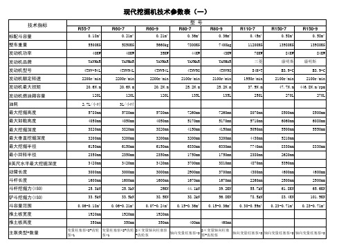
现代挖掘机主要技术参数表
124L
124L
600mm
600mm
2000mm
2000mm
3000mm
3000mm
2
7
130KN
5.5/3.2km/h 5.5/3.2km/h
12r/min
12r/min
70%
70%
2330mm
2310mm
440mm
440mm
2820mm 7820mm 2600mm 2860mm
2640mm 7820mm 2600mm 2640mm
0.92m³
0.92m³
1.05m³
1.05m³
1.35m³
1.35m³
1.38m³
20700KG
20900KG
22100KG
22570KG
25700KG
25700KG
29400KG
112KW
110KW
112KW
112KW
196KW
196KW
190KW
发动机品牌 发动机型号 发动机额定转速 发动机最大扭矩 发动机燃油箱容量 油耗 最大挖掘高度 最大卸载高度 最大挖掘深度 最大垂直挖掘深度 最大挖掘半径 最小回转半径 8英尺水平最大挖掘深度 动臂长度 斗杆长度 斗杆挖掘力(ISO) 铲斗挖掘力(ISO) 斗容量范围 推土板宽度 推土板高度 主泵类型*数量 主泵最大流量 液压油箱容量 履带板宽度 履带中心距/轨距 履带接地长度(轮间距) 托链轮数量(每侧)
6610mm 5650mm 2990mm 95.1KN 132.4kN
现代 D6BV-C 1950r/min
400L
康明斯 B5.9-C
1950r/min 613.5N.m/rpm
旋叶式压缩机型线设计与理论研究1
重庆大学硕士学位论文
英文摘要
equation having good performance and obtained new-type combination profile through applying the basic theory of profile design. The rotary vane compressor using this new-type have a large displacement ,high compression efficiency and volumetric efficiency, no moving shock and mutation of velocity and acceleration for leaves. it also improved the seal between the cylinder and the rotor. This technology had been applied for national invention patent (patent application No. 201010517105.6) in the substantive review stage currently. 5 Developed a CAD system for design and analysis of the rotary vane compressor based on the Windows environment, provided rapid design and analysis tools of rotary vane compressor’s new products. Keywords:Rotary vane compressor, motion law, envelope principle, composite curve
朔德335845自然吸气4.25英寸6气匠柴油引擎筛选说明书

APPLICATION: Combines: 6600 After 156500; 6602 After 1500; 7700 After 8000;Tractors: 4230, 4040;QTY ITEM # DESCRIPTION LETTERED ITEMSINCLUDED IN KIT1 951418 Underhaul Kit U1 954422 In-Frame Kit I1 955422 Out-of-Frame Kit O1 956422 Major Kit M 1 956423 Major Kit (Hi-Comp / Hypereutectic Pistons) M6 6 6 6 6 1 1 151526 151524 151527 151519 151115 151486 151521 Sleeve & Piston Assembly Sleeve & Piston Asb (Hi-Comp / Hypereutectic Pistons) Piston Assembly (Late Hi-Ring Design)Liner AssemblyLiner O-Ring Package.002 Liner ShimBlock Repair Insert, Lower Liner Pilot Bore (2 Grooves)MM O I6 151528 Piston Ring Set (1-1/8K 1-3/32 1-3/16)6 6 6 6 6 251167 251168 251169 251171 251172 STD Rod Bearing .002 Rod Bearing.010 Rod Bearing.020 Rod Bearing.030 Rod BearingM M O I U1 1 1 1 1 251222 251223 251224 251225 251226 STD Main Bearing Set w/Thrust Washers .002 Main Bearing Set w/Thrust Washers.010 Main Bearing Set w/Thrust Washers.020 Main Bearing Set w/Thrust Washers.030 Main Bearing Set w/Thrust WashersM M O I U1 1 251521 251522 STD Thrust Washer Set .007 Thrust Washer Set1 1 1 6 12 351537 351345 351527 351161 301114 Head Gasket Set (1) Valve Cover Gasket (2)Manifold Gasket SetIntake Valve Seal (Viton O-Ring)Positive Valve Seal, Optional (Not in Gasket Sets) (3)I1 1 1 1 1 351538 351539 351312 351348 351569 Overhaul Gasket Set wo/Seals Block Gasket Set (4)Pan Gasket Set: Tractors (Incls 4 Gaskets & 5 O-Rings) (5) Pan Gasket: CombinesLower Pan-Clutch Hsg Gasket: Tractors w/SRT or QRT (6) M M O I IUU1 1 1 351152 351153 751179 Front Crank Seal Kit Rear Crank Seal Kit "Seal Housing Gasket - 351342" Rear Seal Housing Bolt Kit (Self Locking Bolts & W ashers)M M M M O O6 6 6 4 1 251518 251519 251244 251259 751182 Pin Bushing (Boreable) Pin Bushing (Honeable) Pin Bushing (.010 Oversize OD) Cam Bearing Rear Cam Plug M M M MMM12 1 1 751163 751263 751183 Rod Bolt Head Bolt KitEx Manifold Bolt Kit (8 Bolts & Washers)M M O I U(1)STD Thin Head Gasket - 351534 / Optional Thick Gasket (Piston Protrusion .009-.017") - 351575 (2)Special Cover Screw - 751256APPLICATION: Combines: 6600 After 156500; 6602 After 1500; 7700 After 8000;Tractors: 4230, 4040;QTY ITEM # DESCRIPTION LETTERED ITEMSINCLUDED IN KIT1 959513 Camshaft Kit C1 959313 Basic Valve Kit B1 959113 Valve Train Kit, Thru #532429 V1 959146 Valve Train Kit, After #532429 V1 551191Camshaft (7) (8) C 1 551186 Cam Thrust Plate (4 Bolt / .187" Thick)1 551278 Cam Gear Bolt, Late or Replacement Cam (1/2 x 2.000") (9)12 551181 Tappet C6 451216 STD Exhaust Valve (10) V V B6 451217 STD Intake Valve (11) V V B12 401141 Service Repair Valve Guide (.502" OD / 3.062" OAL) (12)12 451115 Valve Spring V V B6 451187 Exhaust Rotator V V6 451411 Intake Retainer, Thru #5324296 451187 Intake Rotator, After #532429 V12 451198 Valve Wear Cap24 451164 Keeper (Half) V V B6 451412 STD Exhaust Seat (1.500x1.750x.250) ".010 OS - 451414"6 451413 STD Intake Seat (1.687x1.937x.250) ".010 OS - 451415"6 451257 Rocker Arm, LH6 451258 Rocker Arm, RH1 451264 Rocker Arm Shaft (13) (14)1 551279 Cam Timing Gear1 551182 Crank Timing Gear, Early Design Crank (.750" Wide)1 551158 Crank Timing Gear, Late Design Crank (.910" Wide)1 551281 Injection Pump Drive Gear12 551277 Push Rod1 651216 Oil Pump: Combines1 651218 Oil Pump Drive Gear/Shaft 1 651215 Oil Pump Gear Set1 651221 Oil Pump Intake Screen: Tractors1 651217 Oil Cooler1 751123 Crankshaft (6 Bolt Flange)1 751265 Crank Update Parts Kit (2 Keys, 2 Plugs, Dowel Pin, Gear)1 751151 Damper Pulley: Tractors1 751266 Damper Pulley: Combines6 751255 Connecting Rod "Cap Alignment Sleeve - 751262"1 851365 Fuel Pump2 851211 Thermostat: Tractors (180 Degree) (15)2 851174 Thermostat: Combines (180 Degree)1 851255 Water Pump: Tractors "Overhaul Kit w/Impeller - 851256"1 851254 Water Pump: Combine "Overhaul Kit w/Impeller - 851257"1 851248 Block Heater (Press Fit Design)1 851249 Block Heater (Threaded Plug Design)(7)Cam Key - 551173 (8).193" Gear Spacer - 551198 (9)Cam Gear Washer - 551194(10)Oversizes: .003 - 451394 / .015 - 451395 / .030 - 451396 (11)Oversizes: .003 - 451397 / .015 - 451398 / .030 - 451399。
ISO标准55-C55系列II型紧缩气动杆说明书
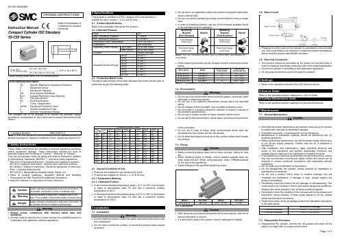
Instruction ManualCompact Cylinder ISO Standard55-C55 SeriesII 2 GDProduct marking shown above is for the standard product.II2provided by compressed air into a force which causes mechanical linearmotion.product is subject to “Special Conditions of Use”, please see Section 2.3.1 Safety InstructionsThese safety instructions are intended to prevent hazardous situationsand/or equipment damage. These instructions indicate the level ofpotential hazard with the labels of “Caution,” “Warning” or “Danger.”They are all important notes for safety and must be followed in additionto International Standards (ISO/IEC) *1), and other safety regulations.*1) ISO 4414: Pneumatic fluid power - General rules relating to systems.ISO 4413: Hydraulic fluid power - General rules relating to systems.IEC 60204-1: Safety of machinery - Electrical equipment of machines.(Part 1: General requirements)ISO 10218-1: Manipulating industrial robots -Safety. etc.∙Refer to product catalogue, Operation Manual and HandlingPrecautions for SMC Products for additional information.∙ Keep this manual in a safe place for future reference.not avoided, will result in death or serious injury.Warning∙Always ensure compliance with relevant safety laws andstandards.∙All work must be carried out in a safe manner by a qualified person incompliance with applicable national regulations.2 SpecificationsThis product is certified to ATEX Category 2GD and therefore issuitable for use in Zones 1, 2, 21 and 22 only.2.1 Product Specifications:Refer to the operation manual for this product;The batch code printed on the label indicates the month and the year ofproduction as per the following table;2.3 Special Conditions of Use:∙Products are suitable for sub-divisions IIC & IIIC.∙Products are suitable for Zones 1, 2, 21 & 22 only.2.3.1 Temperature Marking:2.3.1.1 Standard Product:∙In the normal ambient temperature range (-10°C to +40°C) the productis rated to temperature class T6 and has a maximum surfacetemperature of 84°C.∙In the special ambient temperature range (+40°C to +60°C) the productis rated to temperature class T4 and has a maximum surfacetemperature of 104°C.3 Installation3.1 InstallationWarning∙Do not install the product unless the safety instructions have been readand understood.∙Do not twist or bend the cylinder, or mount the product when subjectto tension.∙Do not use in an application where the product is stopped mid-stroke,via an external stop.∙Do not use where cylinders are being synchronised to move a singleload.∙In order to install the product, use one of the brackets available foundThe “xxx” represents the Bore Size (e.g. Ø40 is 040), see catalogue formore details.∙When replacing brackets use the hexagon wrench and torques shown3.2 EnvironmentWarning∙Do not use in an environment where corrosive gases, chemicals, water,salt water or steam are present.∙Do not use in an explosive atmosphere except within the specifiedrating.∙Do not expose to direct sunlight. Use a suitable protective cover.∙Do not install in a location subject to vibration or impact in excess ofthe product’s specifications.∙Do not use in a place subject to heavy vibration and/or shock.∙Do not use in wet environments, where water can remove the presenceof the lubrication.∙Do not use in case of heavy dusty environments where dust canpenetrate into the cylinder and dry the grease.∙Do not allow dust layers to build up on the cylinder surface and insulatethe product.3.3 PipingCaution∙Before connecting piping make sure to clean up chips, cutting oil, dustetc.∙When installing piping or fittings, ensure sealant material does notenter inside the port. When using seal tape, leave 1 thread exposedon the end of the pipe/fitting.∙Tighten fittings to the specified tightening torque.Model Port Size Model Port Size3.4 LubricationCaution∙SMC products have been lubricated for life at manufacture, and do notrequire lubrication in service.∙If a lubricant is used in the system, refer to catalogue for details.3.5 Basic Circuit∙Plugging one of the ports on the actuator is considered a non-intendeduse, and could relate to an increase in maximum surface temperatureabove what the product specification declares.3.6 Electrical Connection∙The product should be grounded by the piston rod and the body inorder to create an electrically conductive path to the system/application.∙Ground the product in accordance with applicable regulations.∙Do not pass an electrical current through the product.4 Settings∙Refer to the operation manual of the C55 series products.5 How to OrderRefer to the standard product catalogue fo r ‘How to Order’.6 Outline Dimensions (mm)Refer to the standard product catalogue for general dimensions.7 Maintenance7.1 General MaintenanceCaution∙Not following proper maintenance procedures could cause the productto malfunction and lead to equipment damage.∙If handled improperly, compressed air can be dangerous.∙Maintenance of pneumatic systems should be performed only byqualified personnel.∙Before performing maintenance, turn off the power supply and be sureto cut off the supply pressure. Confirm that the air is released toatmosphere.∙After installation and maintenance, apply operating pressure andpower to the equipment and perform appropriate functional andleakage tests to make sure the equipment is installed correctly.∙If any electrical connections are disturbed during maintenance, ensurethey are reconnected correctly and safety checks are carried out asrequired to ensure continued compliance with applicable nationalregulations.∙Do not make any modification to the product.∙Do not disassemble the product, unless required by installation ormaintenance instructions.∙Do not use a product which looks or contains damage, this willinvalidate the certification. If damage is seen, please replace theproduct immediately.∙Periodically check the product for any damage or rust appearing. Thiscould result in an increase in friction and lead to dangerous conditions.Replace the whole actuator if any of these conditions appear.∙Periodically check the condition of the rod seal and for the presence oflubrication, where possible. If these areas appear to be dry, pleasefollow the lubrication procedure.∙Replace the seals, when air leakage is above the allowable value given7.2 Disassembly Procedure∙Disassemble the cylinder, remove the old grease and place all theparts on a clean cloth in a clean environment.ORIGINAL INSTRUCTIONSRefer to Declaration ofConformity for relevantDirectives∙ The snap ring pliers shall be used to remove the retaining ring.∙ Using a fine screwdriver if necessary, remove the old tube gaskets, rod seal, piston seal, wear ring. If there is a magnet present on the piston,do not remove it. This part is not to be replaced.Model Shown: C(D)55(B)20~100-*(M)7.3 Seal Replacement Part NumbersWarningOnly use SMC seal kits as listed in the table below;7.4 Lubrication Procedure∙ Apply lubricant to: • The rod seal.• The rod seal groove on the rod cover.• The piston outer surface and piston seal groove. • The piston seal inner and outer surfaces. • The tube gaskets.• The piston rod surface and cylinder tube internal surface.∙ Lubricate the parts with the grease packs provided with the seal kit.The amount of lubricant to be applied is listed in the following table.7.5 Reassembly Procedure∙ Inserting the collar assembly into the piston rod assembly.Apply grease to the end of the piston rod, especially on the 30° chamfer and on the flats. Insert with care the piston rod into the rod cover to prevent any damage to the rod seal.∙ Inserting piston rod assembly and rod cover assembly into the cylinder tube.Insert slowly with care the piston assembly and the rod cover assembly into the cylinder tube to prevent any damage of the piston seal and tube gasket.∙ Installing retaining ring.Use appropriate pliers (tool for C-Shape Snap Ring) for installation.CautionWhen installing the retaining ring, be aware that the snap ring may come off the pliers and could result in operator injury or equipment damage. Also make sure the ring is firmly seated inside the ring groove before removing the tool.∙ Checking Assembly.Make sure that no air is leaking form the rod seal and that the cylinder operates smoothly at minimum operating pressure. Ensure there is no air leakage.8 Limitations of Use8.1 Limited warranty and Disclaimer/Compliance RequirementsRefer to Handling Precautions for SMC Products located on .8.2 Obligations of the end-user∙ Ensure the product is used within the specification outlined.∙ Ensure that the maintenance periods are suitable for the application. ∙ Ensure any cleaning processes to remove dust layers are made with the atmosphere in mind (e.g. using a damp cloth to avoid static build up).∙ Ensure that the application does not introduce additional hazards by mounting, loading, impacts or other methods.∙ Ensure that there is sufficient ventilation and air circulation around the product.∙ If the product is subject to direct heat sources in the application, they should be shielded so that the actuator temperature stays within the stated operating range.Caution∙ SMC products are not intended for use as instruments for legal metrology.Measurement instruments that SMC manufactures or sells have not been qualified by type approval tests relevant to the metrology (measurement) laws of each country.Danger∙ Do not exceed any of the specifications listed in Section 2 of this document as this will be deemed improper use.∙ Air equipment has an air leakage during operation within certain limits. Do not use this equipment when the air itself introduces additional hazards and could lead to an explosion.∙ Use only ATEX certified auto switches. These should be ordered separately.∙ Do not use this product in the presence of strong magnetic fields that could generate a surface temperature higher than the product specification.∙ Avoid applications where the piston rod end and the adjoining part in the application can create a possible ignition source.∙ Do not install or use these actuators where there is the possibility for the piston rod to impact foreign objects.∙ In the event of damage or failure of any parts located in the vicinity where this product has been installed, it is the responsibility of the user to determine whether or not this has compromised the safety and condition of this product and/or the application.∙ External impact on the cylinder body could result in a spark and/or cylinder damage. Avoid any application where foreign objects can hit or impact the cylinder. In such situations the application should install a suitable guard to prevent this occurrence.∙ Do not use this equipment where vibration could lead to failure.9 ContactsRefer to Declaration of Conformity and for contacts.URL : http// (Global) http// (Europe) 'SMC Corporation, Akihabara UDX15F, 4-14-1, Sotokanda, Chiyoda-ku, Tokyo 101 0021Specifications are subject to change without prior notice from the manufacturer. © 2018 SMC Corporation All Rights Reserved. Template DKP50047-F-085H。
最全各种挖掘机参数一览表
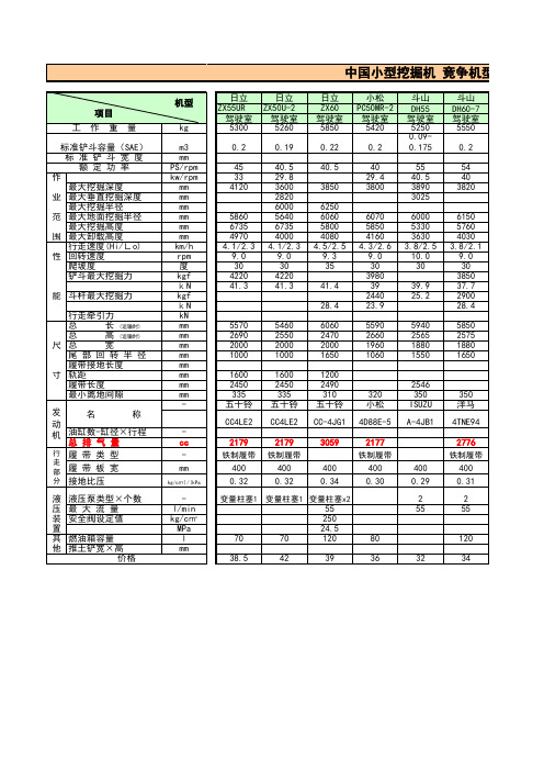
0.2
45 33 4120
5860 6735 4970 4.1/2.3 9.0
30 4220 41.3
40.5 29.8 3600 2820 6000 5640 6735 4000 4.1/2.3 9.0
30 4220 41.3
40.5
3850
6250 6060 5800 4080 4.5/2.5 9.3
驾驶室 5480
神钢 SK55SR
驾驶室 5260
沃尔沃 EC55
驾驶室 5210
玉柴
YC55 驾驶室
5710
0.18
53 40 3820 3050
0.21
54 40 3820
0.18 650 54.3 40.5 3830 3080
0.21 650 41 30.4 3590
0.2
50 37 3820
项目 工作重量
标准铲斗容量(SAE) 标准铲斗宽度 额定功率
作 最大挖掘深度
业 最大垂直挖掘深度 最大挖掘半径
范 最大地面挖掘半径 最大挖掘高度
围 最大卸载高度 行走速度(Hi/Lo)
性 回转速度 爬坡度 铲斗最大挖掘力
能 斗杆最大挖掘力
行走牵引力
总
长 (运输时)
总
高 (运输时)
尺总
宽
尾部回转半径
履带接地长度
cc
-
mm
kg/c㎡)/(kPa
l/min kg/c㎡
MPa l mm
日立 ZX55UR
驾驶室 5300
日立 ZX50U-2
驾驶室 5260
0.2
0.19
日立 ZX60 驾驶室 5850
0.22
现代60-7液压图

60-7 液压图
左侧行走马达
RED
6
T2 T2
右侧行走马达
RED
推土板油缸缸
大臂回转油缸
旋转(选装)
快速转换器(选装)
破碎器(选装)
Ps
Ps
14
17
16
15
32
27
30
11
A B B A
0.5K
0.5K
10
T E B A D C G F
11
A B P T
28
1 主泵 2 主控阀 3 手柄(左侧) 4 手柄(右侧) 5 推土板手柄 6 行走马达 7 回转马达 8 触点 9 梭阀 10 回转接头 11 单向阀 12 单向阀 13 单向阀 14 推土板油缸 15 小臂油缸 16 大臂油缸
a6
a5 T1
a4
a3
a2
17 铲斗油缸 18 液压油冷却器 19 回转滤芯 20 吸油油口 21 通气孔
31 25
MCV a5 ACC MCV b5
5
推土板
22 精滤 3 22
回转 右
3
大臂回转
小臂 左
1
收回 伸出
4
大臂
升 降
铲斗
外翻 收回
13 12
3K
1.5K
4
2
2
4
1
3
22
29
7
A10 b11 sh pg Dr B10 b10 xb9 Dr A9 B9 b9 A8 B8 P1 P2 B7 A7 b6 B6 A6 b5 B5 A5 P3 b4 B4 A4 b3 B3 A3 b2 B2 A2 B1 A1
2
220K
200K
宝马MINI系列R55手册技术资料:mfp-pi_r55_cn
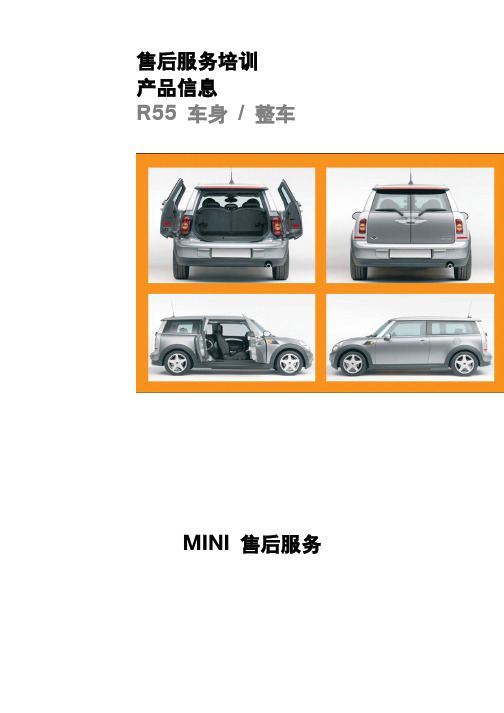
1 – 对开式侧门的分解图
索引 1 2
说明 对开式侧门外侧 对开式侧门内侧
索引 3
说明 对开式侧门分解图
7
对开式侧门位于车辆右侧,与前车门打开方 组合仪表中出现一条 CC 信息“车辆正在运
向相反。
行 - 对开式侧门处于打开状态”。
打开对开式侧门后,可以很方便地进入车辆 后排座椅处。
只有打开前车门后,才能通过内侧开门拉手 打开对开式侧门。如果前车门处于关闭状态 或者旋锁处于预锁止位置,则用于机械断开 开门拉手的安全机构就会阻止打开对开式侧 门。
与 R56 相比,容积增加了 85 升。
后座椅翻下时,地板处长度增加了 281 mm。 与 R56 相比,后座椅翻下时行李箱容积增加
了 250 升。 肩部高度处长度增加了 328 mm。
11
被动安全性
从车辆结构和乘员保护系统角度来看,R55 是一款全新独立的车辆。
5 - R55 乘员室
出色的防撞性能源自其有针对性地使用了高 强度钢板和特殊轧制薄板(车身结构)以及 轻型结构材料,例如铝合金(车门和底盘组 件)和镁合金(车辆横梁)。
12
6 - R55 材料组合
索引 1 2 3 4
说明
索引
其它钢板
5
DC04,DX54D,DX56D
6
HC180BD,HC220BD,HC260BD 7
HC300BD,HC340LAD
8
碰撞负荷经由智能负荷路径而分散。
说明 HC340LAD HC380LAD HC400TD,HC420XD 其它金属
18
12 – 力传递路径 1
前车门内沿对角布置的车门加强梁和一个胸部 区域处铝合金挤压成型部件与 A 柱和 B 柱 一起构成了侧面碰撞变形区域。
