3com total control安装流程
CENTUMCS3000软件的安装步骤
CENTUM CS3000软件的安装步骤CENTUM CS3000/CS1000系统软件的安装步骤如下:1.安装Windows 操作系统。
操作系统的安装方法请参见程序文档ZD0001-A0第一部分或相关手册。
如果PC机上已安装了操作系统,则此步骤可省略。
2.安装Service Pack。
对于Console型HIS(落地式),则此步可省略。
对于Windows2000 SP1,在安装Windows系统的同时也安装了Service Pack 1。
3.Windows设置。
此步骤是为了在Windows上运行CS3000/CS1000系统。
⏹设置或修改虚拟内存和显示画面。
⏹添加网络适配。
安装以太网适配器(如果不需要以太网,则此步可省略)。
安装控制总线驱动程序(如果不需要控制总线,则此步可省略)。
⏹添加打印机。
4.重新安装Service Pack。
注意:如果添加或删除了配置,则此步骤很有必要。
5.安装CS3000/CS1000软件和电子手册。
6.Windows配置。
要在Windows上运行CS3000/CS1000,则需要设置网络、用户名和其它的信息。
当使用“CENTUM”用户名登录时,如果仅使用系统组态,而CS3000/CS1000操作和监视功能不可用。
7.WINDOWS的设置项。
在WINDOWS中,以下信息需要设置:⏹计算机名(站名)。
请确保计算机名和站名是一致的。
如果二者不一致,则不能保证CS3000/CS1000系统能够正确执行。
计算机名用于在Windows网络中标识每一台计算机。
使用Windows 控制面板,可以指定任意一台计算机名。
站点名是CS3000/CS1000系统中根据控制总线地址指定的唯一名称。
例如:HIS0164(HISddss:“dd”是域号,“ss”为站号)。
⏹IP地址。
这是计算机的地址,它可以通过控制总线或以太网来唯一标识该计算机。
请确保在每个子网中指定了控制总线和以太网的地址。
例如:172.16.1.64(控制总线); 172.17.1.64 (以太网)。
Total Commander全能文件管理器使用说明

Total Commander8.0 功能强大的全能文件管理器第一章入门篇一、简介Total Commander 功能强大的全能文件管理器(简称 TC)。
支持随意自定义的菜单、工具栏、快捷键,给您最大的自由,打造个性 TC。
普通的文件操作,如搜索、复制、挪移、改名、删除等功能应有尽有,更有文件内容比较、同步文件夹、批量重命名文件、分割合并文件、创建/检查文件校验 (MD5/SFV) 等实用功能。
内置 ZIP/TAR/GZ/TGZ 格式的压缩/解压功能, ZIP 格式还支持创建加密及自解包功能。
此外,不仅可以直接打开(解开) ARJ/CAB/RAR/LZH/ACE/UC2 等压缩包,配合插件或者相应的压缩程序,更可创建这些格式的压缩包,就像创建和打开文件夹一样简单。
而搜索功能,无论是文件还是内容,同样支持在这些压缩包中进行。
除了支持详细资料、列表、缩略图等资源管理器也有的显示方式外,利用内容插件,支持各式各样的自定义列视图,显示不同文件的内部信息,满足您查看不同文件的需求。
多标签界面,让本来的两个窗口,可以扩展到几十个,操作空间更显自由。
而贴心的历史和常用文件夹按钮,可以导出/导入的文件列表,让您穿越各个空间更加快捷高效。
通过工具栏和菜单,可以随意调用外部程序和内部命令。
多种功能或者强大或者实用的插件,让 TC 如虎添翼、能原来所不能。
批量重命名和文件搜索,利用插件和正则表达式,功能更多更强了。
还有可以选择的美化界面,支持 FXP 和HTTP代理的 FTP 功能,等等等等有了它,资源管理器、 WinZip 及大多数文件管理和工具栏软件,都可以下岗了!Total Commander (原名 Windows Commander )是强大的 windows 资源管理器终结者。
以其使用方便、功能强大、设计体贴、稳定可靠征服了无数电脑老鸟。
在接触、了解这个完美的工具后,相信你会有相见恨晚的感觉。
Total Commander 的最大特点是由两个列表窗口组成,这种设计避免了windows 资源管理器目录树在文件操作的一系列弊端:首先,资源管理器在选择一个文件夹后,如果想先看一下另一个文件夹的内容,就必须先丢失当前的选择,后边要再对先前选择进行操作(复制或者挪移)时又需要重新寻觅上一次选择的文件夹;其次,将一个文件夹在目录树一侧挪移或者复制,如果和目的目录相距较远,是一件极其痛苦的事情——要按着鼠标把文件拖运好远。
3Com Switch 5500 10 100系列用户手册说明书
3COM SWITCH 5500 FAMILY IN AN ENTERPRISE CAMPUS NETWORK5Suggested Service, Support and Training OfferingsNetwork Health CheckAn activity-auditing service focused on improving network performance and productivityIncludes traffic monitoring, utilization analysis, problem identification, and asset deployment recommendations Extensive report provides blueprint for actionNetwork Installation and Experts set-up and configure equipment and integrate technologies to Implementation Servicesmaximize functionality and minimize business disruptionFor large and complex sites, implementation services include personalized configuration, project management, extended testing and coaching on network administrationProject ManagementProvides extra focus and resources that special projects demand 3Com engineers manage entire process from initial specifications to post-project reviewUsing structured methodology, requirements are identified, projects planned and progress of implementation activities tracked3Com Guardian SM Maintenance Service This service provides comprehensive on-site support and includesadvance hardware replacement, telephone technical support and software upgrades 3Com Express SM Maintenance Service This service provides speedy access to: 3Com shipment of advance hardware replacements, software upgrades and telephone support 3Com UniversitySelf-paced and instructor-led technology and product courses, plus certification programs3Com Global Services offers the resources and talents of a major corporation plus more than two decades of experience in resolving network challenges and delivering business benefits to enterprises around the world.Global support with a personalized focus in the local language helps drive productivity and minimize expenses. Because 3Com understands both the technology and the business, we’re the partner you need, to maintain your competitive edge and remain strong.SERVICE AND SUPPORTWarranty3Com Limited Lifetime Warranty. For as long as the original end user owns the product, or for five years after 3Com discontinues the sale of the product, whichever occurs first.Hardware coverageCovers the complete unit including power supply and fan.In-warranty hardware replacement *Advanced Hardware Replacement of hardware for the duration of the warranty. In the US 48 contiguous states this is same-day ship with next business day delivery when call received before noon Pacific time. For Canada, Alaska and Hawaii, this is same-day ship when call received before noon Pacific time. In Western Europe, this is same-day ship when call received before noon Greenwich time. For the rest of the world, it is next-business-day ship. Actual delivery times may vary depending on customer location. Reasonable commercial efforts apply.Software coverage 90 days for media replacement.Software updates*Access to maintenance and bug fix releases for the software version purchased for the duration of the warranty.Online Knowledgebase support*Access to online troubleshooting tool for the duration of the warranty.*These services are not included as part of the Warranty and 3Com reserves the right to modify or cancel this offering at any time, without advance notice. This offering is not available where prohibited by law. Services are effective at warranty start date, and are enabled with product registration. Customers receive a user ID with eSupport registration.PRODUCT WARRANTY AND OTHER SERVICESAll information in this section is relevant to all members of the 3Com Switch 5500 10/100 family, unless otherwise stated.CONNECTORS52-port models48 auto-negotiating 10BASE-T/100BASE-TX ports configured as auto-MDI/MDIX; IEEE 802.3af in-line power for PWR models4Gigabit SFP ports28-port non-FX models24 auto-negotiating 10BASE-T/100BASE-TX ports configured as auto-MDI/MDIX; IEEE 802.3af in-line power for PWR models4Gigabit SFP ports28-port FX24 SFP ports, to be populated with 100BASE-X SFP multi- or single-mode transceivers2auto-negotiating 10BASE-T/100BASE-TX/1000BASE-T ports configured as auto-MDI/MDIX2Gigabit SFP portsPERFORMANCE52-port17.6 Gbps switching capacity,max. 13.1 Mpps forwarding rate, max.28-port12.8 Gbps switching capacity, max. 9.5 Mpps forwarding rate, max.All modelsWirespeed performance across all ports within stack or fabricStore-and-forward switching; latency<10 µs2Gbps full-duplex stacking bandwidthLAYER 2 SWITCHING16K MAC addresses in address table Static MAC addresses: 256 (EI models);64 (SI models); in addition to default addressJumbo Frame support (EI models only) Port-based IEEE 802.1Q VLANs:4,094 (EI models); 256 (SI models) IEEE 802.1 Q-in-Q double-tagged VLANs(EI models only)IEEE 802.1v protocol-based VLANs (EI models only)MAC-based VLANs using RADA auto-VLAN assignmentAuto-voice VLANIEEE 802.3ad Link Aggregation Control Protocol (LACP); automated and manual aggregationLink aggregation trunk groups,per switch:•26 (52-port); 14 (28-port)•810/100 ports or 8 SFP ports per group•8 Distributed Link Aggregation (DLA) groupsAuto-negotiation and manual configuration of port speed and duplex IEEE 802.3x full-duplex flow control Back pressure flow control for half-duplexUnidirectional Link Detection (UDLD)Broadcast, Multicast and Unicasttraffic suppressionIEEE 802.1D Spanning Tree Protocol(STP)IEEE 802.1w Rapid Spanning TreeProtocol (RSTP)IEEE 802.1s Multiple Spanning TreeProtocol (MSTP)Bridge Protocol Data Unit (BPDU)protectionSpanning Tree root guardInternet Group Management Protocol(IGMP) v1 and v2 snoopingIGMP querierFiltering for 256 multicast groupsLAYER 3 SWITCHINGHardware based routingStatic routes: 256 (EI models);64 (SI models);in addition todefault addressAddress Resolution Protocol (ARP)entries: 4K dynamic, 1K static(EI models); 2K dynamic, 256 static(SI models)IP interfaces: 32 (EI models);4(SI models)Routing Information Protocol (RIP),v1 and v2: 2K routes (EI models);1K(SI models)Open Shortest Path First (OSPF)(EI models only):•2 areas with 4 virtual interfacesper area•2neighbors per virtual interface•2virtual linksProtocol Independent Multicast-DenseMode (PIM-DM) (EI models only)Protocol Independent Multicast-SparseMode (PIM-SM) (EI models only)IGMP v1 and v2Equal Cost Multipath Protocol (ECMP)Multicast VLAN Registration (MVR)Dynamic Host Configuration ProtocolRelay(DHCP Relay): 4 K max.(EI models); 2K max.(SI models)3Com XRN®Technology:•Resilient stacking and fabric linksup to 70 km (43.5 mi)•Distributed Link Aggregation, hot-swappable switch units; high-speedfully resilient trunks up to 8 Gbps•Distributed Resilient Routing:optimized Layer 3, one routing tableper switch (EI models only)Virtual Router Redundancy Protocol(VRRP): EI models OnlyCONVERGENCE8hardware queues per portIEEE 802.1p Class of Service/Qualityof Service (CoS/QoS) on ingress andegressRemarking of packets based onpriority:•Type of Service (ToS)•IEEE 802.1p CoS•IP precedence•Physical port•Source/destination MAC address•VLAN information•Ethertype•Source/destination IP address•Source/destination TCP port•Source/destination UDP portWebcache redirection (EI models only)Time-based Access Control Lists(ACLs) (EI models only)Auto-prioritization of voice trafficdetermined by vendor OUIWeighted Round Robin (WRR),including WRR+SPWeighted Fair Queuing (WFQ),including WFQ + SPStrict Priority Queuing (SPQ)Weighted Random Early Discard(WRED)DiffServ Code Point ExpeditedForwarding (DSCP EF) remarking forprioritization of VoIP trafficApplication rate limiting and blockingon ingressPort-based traffic shaping on egressIEEE 802.3af Power over Ethernetstandards-compliant (PWR models)POE (PWR MODELS ONLY)IEEE 802.3af PoE injection into Cat5or 5e LAN wiring (300 W total max.)Supports all standard and mostcommon pre-standard phones, accesspoints and other PoE devices fromselected vendors(Cisco,Nortel,Philips, Siemens, Avaya, NEC,Polycom, Pingtel, Proxim, et. al.)A vailable standards-based supplementalpower system enables full 15.4 W toall PoE ports in a switch or stackSECURITYIEEE 802.1X Network login userauthentication:•Local, RADIUS,or TACACS+ serverauthentication•P AP, CHAP, EAP over LAN (EAPoL),EAP-TLS/TTLS and PEAP•Automatic port assignment ofVLANs,ACLs and QoS profile basedon user•Multiple users per port•1,024 users per fabric•Guest VLAN option•Multiple authentication server realmdefinitionsRADIUS/TACACS+ session accountingRADIUS Authenticated Device Access(RADA): authenticate devices basedon MAC address against RADIUSserver or local database; assign VLANID and ACL through RADIUSCombined MAC and IEEE 802.1Xauthentication on same portDHCP Tracker (EI models only)DHCP snooping, including DHCP TrustWirespeed packet filtering in hardwareACLs filter at Layers 2, 3 and 4:•Source/destination MAC address•Ethernet type•Source/destination IP address•Source/destination TCP port•Source/destination UDP portUser-defined ACL filters(EI models only)Port-based MAC address DisconnectUnknown Device (DUD)IEEE 802.1X or TACACS+ userauthentication of switch managementon Telnet and console sessionsMD5 cipher-text and clear-textauthentication for OSPF v2 and RIPv2 packets and SNMP v3 trafficHierarchical management and passwordprotection for management interfaceand encrypted traffic, with SNMP v3and SSH v24local user access privilege levelsTrusted management station IP and/orMAC addressSTACKINGUp to 400 user ports, including up to384 10/100 portsSingle IP address and managementinterfaces for stack-wide controlHot-swappable, resilient stackingDistributed stacking over standardmedia with links up to 70 km (43.5 mi)XRN Stacking Technology of up toeight units highDistributed Resilient Routing withrouter tables in all units; no master/slave arrangement (EI models only)Stack Switch 5500 EI models onlywith other like units using XRNTechnology via SFP portsStack Switch 5500 SI models only withother like units using SFP portsMANAGEMENTCLI via console or TelnetEmbedded web management interfaceSystem configuration with SNMP v1,2c and 3Comprehensive statistics,includingACL/QoS and IP interfaceSyslogRemote Monitoring (RMON) groupsstatistics,history,alarm and eventsDHCP server including options 60, 82and 184 (EI models only)Supports multiple software images andbank swap, stored in non-volatilememoryConfiguration conversion tool formigration from Switch 3300, 4200and 4400 to Switch 55001-to-1 port mirroringAbility to apply ACL to mirror portand forward only certain traffic typesMany-to-1 port mirroring(EI models only)VLAN-to-1 port mirroring(EI models only)Remote port mirroring (EI models only)Detailed alarm and debug informationFront panel indicators for port andunit status informationSupports ping,remote ping andtracerouteConfiguration file for backup andrestore, stored in non-volatilememory; multiple configuration filesavailableBackup and restore of software imagesNetwork Time Protocol (NTP)DHCP Relay and UDP HelperSystem file transfer mechanisms:Xmodem, FTP, Trivial FTP (TFTP),Secure FTP (SFTP)6 SPECIFICATIONS3Com management applications:•3Com Enterprise Management Suite for flexible, extensible management in advanced enterprise IT environ-ments•3Com Network Director for comprehensive, turn-key network management for the enterprise•3Com Network Supervisor for basic, turn-key network management for mid-market businesses•3Com Network Access Manager for IEEE 802.1X and RADA integration with IAS/Active Directory•3Com Switch Manager for virtual clustering support across 3Com switch familiesDIMENSIONSHeight: 43.6 mm (1.7 in or 1 RU) Width: 440.0 mm (17.3 in)Depth: 270.0 mm (10.6 in)(PWR models: 427.0 mm (16.8 in)) Weight: 3.3 kg (7.3 lb)(PWR models: 6.3 kg (13.9 lb))POWER SUPPLYMode support: AC-only, AC and DC, DC-only operationBuilt-in DC power stage for direct connection to -48 V supplyAC line frequency: 50/60 HzInput voltage: 90-240 V ACAC current rating: 1.0A max. (PWR models: 7.0A max.)DC current rating: 2.0A max. (PWR 28-port: 12.0A;PWR 52-port: 19.5A; max.)ENVIRONMENTALOperating temperature: 0°to 40°C(32°to 104°F)Operating altitude: 0 to 4,572 meters(0 to 15,000 feet)Storage temperature: -40°to 70°C(-40°to 158°F)Humidity (operating and storage):10% to 95% non-condensingStandard: EN 60068 (IEC 68)Sound pressure level (dBA):•52-port: 46.5 decibels•52-port PWR: 46.3 decibels•28-port: 40.1 decibels•28-port PWR: 47.3 decibels•28-port FX: 51.3 decibelsRELIABILITY(MTBF @ 25°C)52-port: 44 years (385,000 hours)52-port PWR: 21 years (184,000 hours)28-port: 53 years (464,000 hours)28-port PWR: 30 years (263,000 hours)28-port FX: 38 years (332,000 hours)INDUSTRY STANDARDSSUPPORTEDEthernet ProtocolsIEEE 802.1D (STP)IEEE 802.1p (CoS)IEEE 802.1Q (VLANs)IEEE 802.1s (MSTP)IEEE 802.1v (Protocol VLANs)IEEE 802.1w (RSTP)IEEE 802.1X (Security)IEEE 802.3 (Ethernet)IEEE 802.3ab(1000BASE-T)IEEE 802.3ad (Link Aggregation)IEEE 802.3af (Power over Ethernet)IEEE 802.3i (10BASE-T)IEEE 802.3u (100BASE-TX/-FX)IEEE 802.3x (Flow Control)IEEE 802.3z (1000BASE-X)Management, including MIBsSupportedRFC 768 (UDP)RFC 783 (TFTP)RFC 791 (IP)RFC 792 (ICMP)RFC 793 (TCP)RFC 826 (ARP)RFC 1058 (Routing InformationProtocol)RFC 1112 (IP Multicasting)RFC 1157 (SNMP)RFC 1213/2233 (MIB II)RFC 1253 (OSPF Version 2 MIB)RFC 1583 (OSPF Version 2)RFC 1587 (OSPF NSSA Option)RFC 1724 (RIP Version 2 MIBExtension)RFC 1757 (RMON)RFC 1812 (Requirements for IPv4Routers)RFC 1850 (OSPF Version 2 MIB)RFC 1907 (SNMP Version 2c MIB)RFC 2021 (RMON II Probe ConfigMIB)RFC 2154 (OSPF Digital Signatures)RFC 2233 (Interfaces MIB)RFC 2236 (IGMP V2)RFC 2328 (OSPF Version 2)RFC 2338 (VRRP)RFC 2362 (PIM-SM)RFC 2571 (FrameWork)RFC 2571-2575 (SNMP)RFC 2613 (Remote NetworkMonitoring MIB Extensions)RFC 2618 (RADIUS AuthenticationClient MIB)RFC 2620 (RADIUS Accounting ClientMIB)RFC 2644 (Restricted DirectedBroadcast)RFC 2665 (Pause Control)RFC 2668 (IEEE 802.3 MAU MIB)RFC 2674 (VLAN MIB Extension)RFC 2819 (RMON groups Alarm,Event, History and Statistics only)RFC 2819 (RMON MIB)RFC 3414 (SNMP Version 3 USM)RFC 3415 (SNMP Version 3 V ACM)SNMP v3 and RMON RFC supportEMISSIONS / AGENCY APPROVALSCISPR 22 Class AFCC Part 15 Class AEN 55022 1998 Class AEN 61000-3-2 2000, 61000-3-3ICES-003 Class AVCCI Class AIMMUNITYEN55024SAFETY AGENCY CERTIFICATIONSUL 60950IEC 60950-1EN 60950-1CAN/CSA-C22.2 No. 60950-1-03WARRANTY AND OTHER SERVICESLimited Lifetime Hardware Warranty,including fans and power supplyLimited Software Warranty for 90 daysAdvance Hardware Replacementwith Next Business Day shipment inmost regions90 days of telephone technical supportRefer to /warrantyfor details.SPECIFICATIONS (CONTINUED)REDUNDANT POWER SYSTEM 3Com has tested and qualified a Redundant Power System (RPS) solution designed for the Switch 5500 family by Eaton Powerware Corporation, a leading global provider of power quality and management solutions. The Powerware DC RPS systems come in either 3RU or 6RU form-factors, delivering up to 9,000W of DC power to a stack of Switch 5500 units. The 3RU RPS unit houses up to three hot-swappable rectifiers supplying up to 4,500W of power that supports up to eight separately-fused DC outputs, while the 6RU unit can house up to six hot-swappable rectifiers provisioning a total of 9,000W.The RPS supports SNMP management, including MIB II, which is easily accessible through the built-in RJ-45 or serial port. It is fully compatible with the IEEE 802.3af Power over Ethernet standard, providing supplemental power for the 3Com Switch 5500 PWR models.With this RPS, all 384 10/100 ports on a stack of eight Switch 5500 PWR 52-port units can receive the industry standard15.4W of power per port, with N+1 power redundancy.The RPS ships with the power input fully configured and can be connected to a UPS with battery backup. For more details, please refer to /rps.7。
3Com Modem Xem 系列产品安装指南

3.Attach power supplies to all Modem/Xem modules, and thePORTS/Xem modules that need auxiliary power, and then plug power supplies into AC receptacles.Turn on power to Modem/Xem modules using the power switch on the left side of the module. (PORTS/Xem modules do not have apower switch.)Step Four: (Modem/Xem only) Set the speakercontrolEach Modem/Xem module has an internal speaker which will provide audio output for any one of the modem ports in the module. You can select the modem port that is to be connected to the speaker or select not to use the speaker, via a DIP switch on the rear of the unit.See the hardware information that came with your Modem/Xem for the switch settings to use.There is a speaker volume control on the left side of the module.Step Five: Install peripheral cablingModem/XemUse standard RJ-11C telephone cables to connect Modem/Xem modules to the telephone lines. Connect to analog telephone circuits only. Never connect a modem module to a digital wall jack. Note that internal tele-phone systems (such as a PBX, Private Branch Exchange), may be digi-tal.Also, the Modem/Xem modules are to be used only with public access phone lines. Leased line operation is not supported.Most phone systems are “loop start” but some are “ground start.” The Modem/Xem will not operate with “ground start” phone systems. PORTS/XemYou can connect printers, terminals, modems (or any other standard EIA-232 device to be controlled by applications on the computer) to the PORTS/Xem modules. The cable connector on the peripheral end depends on the requirements of the peripheral. The PORTS/Xem end of the cable must fit either an RJ-45 or DB-25 connector, depending on the module option you have.The pin assignments for each type of PORTS/Xem connector are shown on the back.Refer to the CD-ROM for more detailed cabling information.What Next?At this point the hardware installation for your PORTS/Xem orModem/Xem system is complete. However, since the adapter must havesoftware downloaded to its internal RAM before it becomes functional,you must next install the software driver for your operating system.•Read the instruction booklet for the CD-ROM that came with yourXem system for instructions on installing software.•View the on-line documentation on the CD-ROM for more informa-tion about AccelePort products.The Digi logo and AccelePort are registered trademarks of Digi International. Xem,PORTS/Xem, PORTS/8em, PORTS/16em, Modem/4em, Modem 8/em, and Modem/Xemare trademarks of Digi International. All other brand and product names are trademarks oftheir respective holders.© Digi International Inc., 1998; All Rights Reserved; Information in this document is subject to change without notice and does not represent acommitment on the part of Digi International.Digi provides this document “as is”, without warranty of any kind, either expressed orimplied, including, but not limited to, the implied warranties of fitness or merchantabilityfor a particular purpose. Digi may make improvements and/or changes in this manual or inthe product(s) and/or the program(s) described in this manual at any time.This product could include technical inaccuracies or typographical errors. Changes are peri-odically made to the information herein; these changes may be incorporated in new editionsof the publication.AccelePort Xem SystemXem ISA Host AdapterPORTS/8em, PORTS/16em ModulesModem/4em, Modem/8em ModulesHardwareInstallation GuideIntroductionAn AccelePort® Xem™ system consists of an Xem adapter coupled withPORTS/Xem™ modules (PORTS/8em™ and PORTS/16em™) and/orModem/Xem™ modules (Modem/4em™ and Modem/8em™). ThePORTS/Xem modules easily expand the number of EIA-232 ports onyour computer, allowing you to cable additional peripheral devices suchas printers, terminals or modems to your computer. Modem/Xem mod-ules contain either four or eight modems.The Xem adapter can support up to four modules. Multiple modules ofeither type can be linked in a chain to expand the number of EIA-232ports and/or modems available.Figure 1. Example setupThis installation guide describes how to plan your Xem system setup andinstall the adapter and module hardware.DB-25 Pin assignments RJ-45 Pin AssignmentSignal Description Pin Signal Description PinGND Chassis Ground1*RI Ring Indicator1TxD Transmitted Data2DSR Data Set Ready2†RxD Received Data3RTS Request T o Send3RTS Request To Send4GND Chassis Ground4CTS Clear To Send5TxD T ransmitted Data5DSR Data Set Ready6RxD Received Data6SG Signal Ground7SG Signal Ground7DCD Data CarrierDetect8CTS Clear T o Send8DTR Data T erminalReady20DTRData TerminalReady9RI Ring Indicator22DCD Data CarrierDetect10* Chassis Ground is also availableon the connector shell† Pin 2 can be configured for DCD(through Digi software) if you wantto connect using an 8 pinconnector91000741 AStep One: Plan your setupAn AccelePort Xem system can be set up in a variety of ways. Before you start your installation, be sure of the following:Number and type of components. Each Xem host adapter has an EBI bus onto which you can cable up to four modules (of just one type or combined PORTS/Xem and Modem/Xem).Location of components. The first module on the EBI bus can be located up to five feet from the adapter (the length of the cable that comes with the system). Additional modules can then be stacked on top of the first module using the shorter cables provided with the add-on modules.Note:The cumulative length of cable from the Xem adapter to the last module should not exceed ten feet.To remain in compliance with emissions standards, you must use the cables that come with the product; the EBI cables cannot be extended. Peripheral cabling. Before beginning the installation, be sure that you have the cables that you will need for the peripherals that you will be attaching to the modules. PORTS/Xem modules are available with either RJ-45 or DB-25 connectors for peripheral cabling.Modem/Xem modules accommodate modular phone line connectors.You will need to be sure that you have cables of the correct length and with the right connectors to properly attach the devices you want to use with each module.Power requirements. The first two PORTS/Xem modules can obtain power from the EBI bus. However, as you add PORTS/Xem modules to the EBI bus you must evaluate whether an auxiliary power supply will be necessary for the additional modules.In general, the third and fourth PORTS/Xem modules on the EBI bus will require auxiliary power.Note:If there is sufficient power for the module, the LED indica-tor on the side panel of the PORTS/Xem module will light.Each Modem/Xem module requires its own power supply.Before proceeding with the installation, you should determine if there is a need for auxiliary power supplies (available for purchase from Digi) and also determine that adequate power is available where mod-ules will be installed.Additional information about the Xem system, such as specifications and cabling details, is provided on the CD-ROM that is packaged with the host adapter.Step Two: Install the Xem ISA adapterBefore installing the Xem adapter, you should do the following:•Check system resources for a free I/O port address. The Xem adapteruses four bytes of address space on the I/O bus of the computer intowhich you are installing it.•Wear an ESD wrist strap to ground yourself while handling theadapter. If one is not available, discharge static electricity from yourbody by touching an unpainted metal surface, such as the computer’schassis, prior to handling the adapter.•Record the adapter serial number, which will enable Digi to provideyou with better service, should the need arise. The serial number labelhas this general format: S/N: (S) XXX XXXXX•Unplug power from the PC.Figure 2. Xem ISA adapter1.Set the I/O port address of the adapter to one of the followingaddresses using the DIP switch at the location indicated in Figure 2:2.Remove the computer’s cover.3.Locate an available ISA slot in your computer and remove the slotplate.4.Insert the adapter into the slot and screw the endplate to the computerchassis. The endplate must be screwed into the computer chassis toremain in compliance with Part 15 of FCC rules.5.Replace the computer’s cover.6.Attach one end of the EBI cable to the connector on the adapter.Note:Do not power on the host system yet.Step Three: Install modulesDuring this step (and whenever EBI cables are attached or removed fromthe modules) the host system must be turned OFF and power must not beapplied to the modules.1.Position modules at the location you have prepared according to theplan you developed in Step One.2.Attach the cable from the adapter to the connector labelled EBI IN onthe first PORTS/Xem or Modem/Xem module that is to be connected.Figure 3. Side Panel of PORTS/Xem module.Figure 4. Side Panel of Modem/Xem moduleIf you are cabling multiple modules together, attach a daisy-chaincable to the EBI OUT connector of the first module. Connect the otherend to the EBI IN connector of the second module. Continue cablinguntil all modules in the string are cabled.I/Oaddress1234104-107h up up down down114-117h up down up down124-127h up down down down204-207h down up up down224-227h down up down down304-307h down down up down324-327h down down downdown。
3COM 1200 1201用户手册.pdf说明书
USER MANUALMODEL 1200/1201SynchronousModem EliminatorSALES OFFICE (301) 975-1000TECHNICAL SUPPORT P/N: 07M1200-CDoc# 049011U,Rev. DRevised 1/22/081.0Warranty Information (5)1.1Warranty Statement (5)1.2Radio and TV Interference (5)1.3CE Notice (6)1.4Service (6)2.0General Information (7)2.1Features (7)2.2Description (7)3.0Installation (8)4.0Configuration (9)4.1Data Rate (9)4.2Carrier Detect (9)4.3RTS/CTS Delay (10)4.4Ground (10)5.0Operation (11)5.1LED Status Indicators (Model 1201 only) (11)A Specifications (12)A.1Data Rates (12)A.2Clocking (12)A.3Grounding (12)A.4Range (12)A.5Functional (12)A.6RTS/CTS Delay (12)A.7DCD (12)A.8Ring Indicator (12)A.9Interface (12)A.10Connectors (12)A.11Power Supply (12)A.12Altitude (12)A.13Humidity (12)A.14Dimensions (12)B Block Diagram (13)1.0 WARRANTY INFORMATIONPatton Electronics warrants all Model 1200/1201 components to be free from defects, and will—at our option—repair or replace the product should it fail within one year from the first date of shipment.1.1 WARRANTY STATEMENTPatton Electronics warrants all Model 2701RC Series components to be free from defects, and will—at our option—repair or replace the prod-uct should it fail within one year from the first date of shipment. This war-ranty is limited to defects in workmanship or materials, and does not cover customer damage, abuse, or unauthorized modification. This prod-uct contains no serviceable parts; therefore the user shall not attempt to modify the unit in any way. If this product fails or does not perform as warranted, your sole recourse shall be repair or replacement as described above. Under no condition shall Patton Electronics be liable for any damages incurred by the use of this product. These damages include, but are not limited to, the following: lost profits, lost savings and incidental or consequential damages arising from the use of or inability to use this product. Patton Electronics specifically disclaims all other war-ranties, expressed or implied, and the installation or use of this product shall be deemed an acceptance of these terms by the user. In the event the user detects intermittent or continuous product malfunction due to nearby high power transmitting radio frequency equipment, the user is strongly advised to use only data cables with an external outer shield bonded to a metal or metalized connector.1.2 RADIO AND TV INTERFERENCEThe Model 1200/1201 generates and uses radio frequency energy, and if not installed and used properly-that is, in strict accordance with the man-ufacturer’s instructions-may cause interference to radio and television reception. The Model 1200/1201 has been tested and found to comply with the limits for a Class A computing device in accordance with specifi-cations in Subpart B of Part 15 of FCC rules, which are designed to pro-vide reasonable protection from such interference in a commercial installation. However, there is no guarantee that interference will not occur in a particular installation. If the Model 1200/1201 does cause interference to radio or television reception, which can be determined by disconnecting the unit , the user is encouraged to try to correct the inter-ference by one or more of the following measures: moving the computing equipment away from the receiver, re-orienting the receiving antenna and/or plugging the receiving equipment into a different AC outlet (such that the computing equipment and receiver are on different branches).1.3 CE NOTICEThe CE symbol on your Patton Electronics equipment indicates that it is in compliance with the Electromagnetic Compatibility (EMC) directive and the Low Voltage Directive (LVD) of the European Union (EU). A Cer-tificate of Compliance is available by contacting Technical Support.This device is not intended to be connected to the publictelephone network.Caution1.4 SERVICEAll warranty and nonwarranty repairs must be returned freight prepaid and insured to Patton Electronics. All returns must have a Return Materi-als Authorization number on the outside of the shipping container. This number may be obtained from Patton Electronics T echnical Services at:•Tel: +1(301) 975-1007•Email: ******************•URL: Note Packages received without an RMA number will not beaccepted.2.0 GENERAL INFORMATIONThank you for your purchase of this Patton Electronics product. This product has been thoroughly inspected and tested and is warranted for One Y ear parts and labor. If any questions or problems arise during installation or use of this product, please contact Patton Electronics Customer Service at (301) 975-1007.2.1 FEATURES•Smallest synchronous modem eliminator available•Data rates to 38.4 Kbps•Synchronous cable runs to 300 feet on each side of device •Constant or RTS controlled carrier selections•RTS-CTS delay options of 0mS, 6.6mS or 53mS•DB-25 connector on each end•Half or full duplex•Internal or external clocking•No external power required•LEDs monitor data and control signals (Model 1201 only)2.2 DESCRIPTIONMeasuring only 5.3 x 2 x 1.2 inches, the Patton Model 1200 is the small-est self-powered synchronous modem eliminator on the market. All power is derived from the RS-232 data signals, so no AC power or bat-teries are required. Constructed with a DB-25 connector on each end, the Model 1200 can extend synchronous cable runs to 300 feet on each side of the device. Optimum distance is achieved at 9600 bps, and strap selectable data rates may extend up to 38,400 bps.The Model 1200 provides internal or external clock options and operates half or full duplex. To emulate dial-up or dedicated service, the delay between RTS and CTS can be set to either 0mS, 6.6mS or 53mS. The carrier can be configured either as “constantly on” or “controlled by RTS”. The Model 1201 has all the features of the Model 1200, plus LED indica-tors that monitor receive data, request to send and data carrier detect on each side of the device.Do the following to install the Patton Model 1200:1.Configure according to the instructions listed in section 4.0, “Config-uration” on page 7.2.Turn off the computer or device to which the Model 1200 is to beconnected.3.Plug the DB-25 connectors directly into the serial ports of your RS-232 devices. If you wish to extend the distance, you can add cableson both sides (see Figure 1).Note Cables must not be longer than 300 feet (see Figure 1).Figure 1.ConfigurationThe Model 1200 is equipped with four strapping options that allow config-uration to a wide range of applications. To gain access to the internal straps, loosen the hex nuts on the DB-25 connectors and pry open the case between the plastic shell ears. Figure 2 shows the location of each strapping option.Figure 2. Strap settings for the Model 1200/12014.1 DATA RATEThe data rate strap controls the rate at which data is transmitted. Adjust the strap to select one of the following options: 1.2, 2.4, 4.8, 9.6, 19.2, 38.4 or external clocking. If “external clocking” is selected, the Model 1200 will automatically match the clocking between your two synchro-nous devices. The default setting is 9.6 Kbps.4.2 CARRIER DETECTThe carrier detect straps allow you to determine whether the carrier is “constantly on” or “controlled by RTS”. By adjusting the strap, you may operate in switched carrier, multi-point and/or hardware handshaking applications. Port 1 and port 2 may be configured separately. The defaults setting is “on” for both ports.4.3 RTS/CTS DELAYThe RTS/CTS delay straps determine the amount of delay between the time the Model 1200 “sees” RTS and when it sends CTS. In order to emulate either dial-up or leased line modems, you can set this strap at either no delay, 6.6mS or 53mS. Port 1 and port 2 may be configured separately. The default setting is 6.6mS for both ports.4.4 GROUNDThe ground strap setting connects the protective ground from port 1 or 2 to the Model 1200’s signal ground. The default setting is port 1.5.0 OPERATIONOnce you have configured the Model 1200 properly (see section 4.0, “Configuration” on page 7) and plugged it into your equipment, you are ready to operate the unit. After the Model 1200 is properly installed, it should operate transparently—as if it were a standard cable connection. Operating power is derived from the RS-232 data and control signals; there is no “ON/OFF” switch.5.1 LED STATUS INDICATORS (MODEL 1201 ONLY)The Model 1201 features six front panel status LEDs that indicate the condition of the modem eliminator and the communication link. The dia-gram below shows the location of each of these LEDs. Following the dia-gram is a description of each LED’s function.•“TD” and “RTS” indicators blink with data activity.•“CD” lights for an incoming signal on the line side and the resulting out-put signal on the RS-232.APPENDIX ASPECIFICATIONSA.1 DATA RATESSelectable: 1200, 2400, 4800, 9600, 19200, 38400A.2 CLOCKINGInternal or externalA.3 GROUNDINGProtective ground (pin 1) may be strapped to signal ground (pin 7)A.4 RANGE300 feet on either side (for a total of 600 feet) at 9600 bps, range extends linearly for lower bit rates and decreases for higher bit ratesA.5 FUNCTIONALEmulates half or full duplex, dial-up or dedicated lineA.6 RTS/CTS DELAYSelectable per port: 0mS, 6.6mS, 53mSA.7 DCDSelectable per port: continuous or RTS controlledA.8 RING INDICATORConstantly onA.9 INTERFACEEIA RS-232C/CCITT V.24A.10 CONNECTORSChoice of two male or two female DB-25 RS-232 connectorsA.11 POWER SUPPLYNone requiredA.12 ALTITUDE0 to 10,000 feetA.13 HUMIDITYUp to 95% non-condensingA.14 DIMENSIONSApproximately 5.3 x 2 x 1.2 in.APPENDIX BBLOCK DIAGRAMCopyright © 2001 Patton Electronics Company All Rights Reserved.Dear Valued Customer,Thank you for purchasing Patton Electronics products! We do appreci-ate your business. I trust that you find this user manual helpful.We manufacture one of the widest selections of data communications products in the world including CSU/DSU's, network termination units, powered and self-powered short range modems, fiber optic modems, interface converters, baluns, electronic data switches, data-line surge protectors, multiplexers, transceivers, hubs, print servers and much more. We produce these products at our Gaithersburg, MD, USA, facility, and can custom manufacture products for your unique needs.We would like to hear from you. Please contact us in any of the following ways to tell us how you like this product and how we can meet your prod-uct needs today and in the future.Web: Sales E-mail: ****************SupportE-mail:******************Phone - Sales (301) 975-1000Phone - Support (301) 975-1007Fax: (301) 869-9293Mail: Patton Electronics Company7622 Rickenbacker DriveGaithersburg, MD 20879 USAWe are committed to a quality product at a quality price. Patton Electron-ics is ISO 9001 certified. We meet and exceed the highest standards in the industry (CE, UL, etc.).It is our business to serve you. If you are not satisfied with any aspect of this product or service provided by Patton Electronics or its distributors, please let us know.Thank you.Burton A.PattonVice PresidentP.S. Please tell us where you purchased this product.________________________________________________________ ________________________________________________________ ________________________________________________________。
Total Commander 使用手册
Total Commander 使用手册设置篇•增加驱动器按钮打开“外观”选项卡,选中“显示磁盘按钮”及它下方的两个复选框。
这时每个窗口的上方会出现一排驱动器按钮,切换驱动器时更加方便。
•操作方式打开“操作方式”选项卡,在“鼠标选择方式”组框中选中“用鼠标左键”,“选择文件”组框选中“同时选择文件夹”,保持和资源管理器选择方式相同。
“快速搜索”组框中选中“字母(显示快速搜索栏)”,用于在目录中快速定位文件,单击一个字母即可跳到相应字母开头的文件,但不能使用中文。
•显示设置打开“显示”选项卡,“文件夹排序方式”组框中选中“和文件一样”。
“说明文字”组框中选中“按屏幕提示显示缩略词”,当文件名无法完全显示时以提示框显示。
不要选中“以小写显示 8.3 式文件名(如资源管理器)”,避免文件名的大小写与实际不符。
•对齐方式打开“对齐方式”选项卡,在“文件扩展名”组框中选中“直接跟在文件名后面”。
“字节显示”选择“ K 字节”(与资源管理器相同)。
•内置查看器设置打开“编辑 / 查看”选项卡,单击“设置内部观察程序”按钮,把“启动时显示模式”设为“文本”,“启动时字体”设为“ ANSI ”,这是 Windows 使用的字符集。
按Shift + F4是新建一个文本文件调用“编辑 / 查看”选项卡设定的“编辑程序”来进行编辑。
•设置初始化文件Total Commander 的很多重要设置都保存在 wincmd.ini 文件中。
下面提到的多数项目都不存在,请自行添加,所有设置在下次启动 Total Commander 时生效。
[Configuration]AlwaysCopyInBackground=0 总在后台拷贝。
设为 1 时,总在后台拷贝。
AlwaysToRoot=1 如果设为 1,切换驱动器时总是转到根目录。
ActiveRight=1 如果设为 1,运行TC后默认当前窗口在右边。
CdCloseDoor=1 如果切换到光盘驱动器失败,尝试关闭光驱门。
Total Commander教程_初级
TC(张学思版)使用简介前言TC,即total commander,是一款很强大的资源管理工具。
几乎所有的操作都可以用可以用快捷键完成,用此工具的目的就是快速操作。
抽空写一个简易的使用说明,供大家入手。
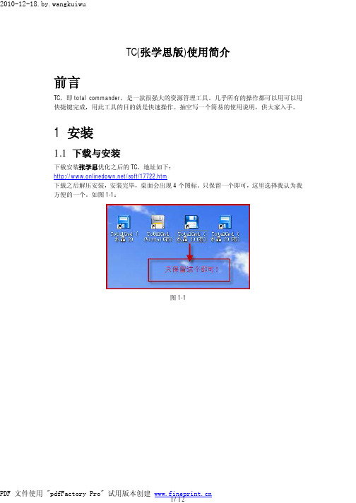
1 安装1.1 下载与安装下载安装张学思优化之后的TC,地址如下:/soft/17722.htm下载之后解压安装,安装完毕,桌面会出现4个图标。
只保留一个即可,这里选择我认为我方便的一个。
如图1-1:图1-11.2全局快捷键设置右击图标,选择“属性”打开属性对话框;然后,在快捷键上设置“ALT+F1”。
这样,在任何时候按“ALT+F1”就可以打开TC的窗口。
如图1-2:图1-22 设置按“ALT+F1”,打开TC的窗口,依次进行如下设置。
2.1依次按“ALT+0”(隐藏工具栏)、“ALT+3”(隐藏工具按钮)、“CTRL+H”(隐藏系统/隐藏文件)。
如图2-1:图2-1选择“视图->屏幕布局->两个驱动器按钮按钮栏”,实现在左右两边分别显示各个驱动器的信息,如图2-2:图2-2选择“设置->选项”,打开TC设置对话框,依次对显示、操作等进行设置。
如图2-3:图2-3选择“字体”,可对文件列表、窗口标题栏以及对话框等的字体进行设置。
如图2-4:图2-4选择“对齐方式”,可以对显示的文件名、扩展名、大小、日期时间等进行设置。
如图2-5:图2-5选择“操作->鼠标选择方式->使用鼠标左键选择”;取消选择“操作->主程序->单击打开文件和文件夹”。
这样,在TC中使用鼠标的习惯就能保持和windows下一致。
如图2-6:图2-6选择“查看/编辑”,在“编辑程序”输入框中输入ultra edit的可执行文件的路径。
这样,在TC中选中文件,然后F4就可以直接用UE打开文件了。
如图2-7:图2-7其它的设置项,可以根据自己的习惯进行选择。
3 常用快捷键3.1查看快捷键选择“帮助->快捷键列表”打开快捷键列表。
Total control处理流程1
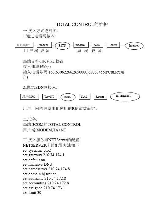
TOTAL CONTROL 的维护一.接入方式连线图:1.通过电话网接入:局端支持v.90和x2 协议接入速率56kbps接入电话号码:163,63062266,2650000,63063456(PUBLIC2用户)2.通过ISDN 网接入:用户上网的速率由他使用的B 信道数而定。
二.设备:局端:3COM 的TOTAL CONTROL用户端:MODEM,TA+NT三.接入服务器NETServer 的配置:NETSERVER 卡的配置方法如下set sysname bto2set gateway 210.74.174.1set default onset namesvc DNSset nameserver 210.74.174.8set domain set authentic 210.74.172.8set accounting 210.74.172.8set assigned 210.74.173.1set limit 30set ccp offset !rootaccess offset modem startslot 15set modem density 15 30set modem s1-s30 activeset all login network dialinset all security onset all service_login telnetset all modem onset pppmodem onset all message ^^ I am Hiper ! ^^set all prompt username:set net0 address 210.74.172.16set net0 netmask 255.255.255.0set net0 routing onsave allreboot四. TOTAL CONTROL的网关:1.163 MODEM拨号TC:LanSwitch:B架网关-- 202.99.38.65 LanSwitch: C架网关 GW 202.99.38.81D架网关 GW 202.96.0.1 (RTR-C4/1/6 )E架网关 GW 202.96.0.17 (RTR-C-4/1/7 )高密: F架网关 202.99.60.65 (RTR-F-0/0/6 )网关 202.99.60.73 (RTR-F-0/0/7 )网关 202.99.60.81 (RTR-E-3/1 )最新架 : GW 202.99.54.1 (RTR-C-4/0/0)2.163 ISDN拨号TC:NAS地址网关202.99.54.38 202.99.54.35202.96.0.68 202.96.0.66 202.96.0.69 202.96.0.663.169 MODEM拨号 TC:F架网关 GW 10.2.68.994.PUBLIC2的拨号用户:网关GW 202.96.12.65五.故障诊断:1.E1线告警,可用测试线63068000替换它,看状态.如果正常,说明E1线有问题,给4000门打电话,请他们帮助解决.2.如果某一块卡"死"了,可插拔一下.3.用户反映拨号上不来,可用拨号测试机试一下,如没问题,则问题在用户或PSTN一侧.4.看用户当前状态,TELNET到NETSERVER上,执行以下命令: command>show sessions5.清除一个用户, TELNET到NETSERVER上,执行以下命令: command>reset Sn(n为相应的端口)6.如发现路由有问题,可到NETSERVER上traceroute一下,看到网关有没有问题,如没问题,则问题不在TOTAL CONTROL.。
科密消费机 管理系统详细安装步骤带图 By穷才懒人-推荐下载
科密消费机管理系统详细安装步骤带图By:穷才懒人1.一般使用步骤1> 获取安装程序,安装包中的文件分两部分:消费管理系统安装包、MSDE(Microsoft Sql Server Desktop Engine)。
2> 运行Setup.exe,开始安装系统。
3> 选择所要使用的语言,单击“确定”。
4> 之后弹出欢迎使用安装向导,准备安装。
5> 修改安装路径后,单击“下一步”。
6> 安装设置完毕,单击“下一步”开始拷贝文件。
7> 安装程序自动拷贝文件,建立快捷方式。
8> 显示安装完毕窗口。
9> 安装消费管理应用程序完毕,单击“完成”后开始提示安装所选择的MSDE。
10> 提示是否开始自动安装MSDE,选择“是”开始安装。
11> 安装完毕。
桌面、和开始菜单出现消费管理系统图标。
2.常见问题解答1> 如果用户电脑已经安装有Microsoft Sql Server 2000的任何版本,可不用再安装MSDE,仅安装消费管理应用程序即可。
2> MSDE为Microsoft公司的免费桌面数据库,用户可以自行下载。
3.注意事项1> 用户可以从Microsoft公司下载必要的MSDE补丁程序完善数据库后台管理。
2> 电脑最低配置:128M内存,CPU800MHz,硬盘1G空间。
4.警告1> 没有安装MSDE或Sql Server的其它版本前,不能运行消费管理系统(连接其它电脑的数据库时,本机无需安装SQL Server)。
数据库设置1.功能介绍在初次运行系统时创建数据库或连接已有数据库,设置数据库连接参数。
2.一般使用步骤1> 初次运行程序,出现数据库设置窗口:注:若本机服务器已启动的选项没有选中,说明本机的SQL没有启动,可手动启动或重新登录2> 数据库服务器指消费管理系统的后台Sql Server服务器,单机版为MSDE,网络版为MSDE或Sql Server 2000的其它版本。
C3系列控制器安装指南

C3系列控制器安装指南C3系列控制器安装指南1. 概述1.1 系统介绍1.2 安装前准备1.3 安全注意事项2. 硬件安装2.1 控制器组件2.2 室内布线2.3 外部连接2.3.1 电源连接2.3.2 网络连接2.4 控制器安装2.4.1 安装位置选择2.4.2 控制器固定3. 软件配置3.1 系统要求3.2 控制器初始化3.2.1 网络设置3.2.2 时间设置3.3 控制器配置3.3.1 输入输出配置3.3.2 用户权限设置4. 系统测试与调试4.1 控制器连接测试4.2 输入输出测试4.3 联动测试4.4 告警测试5. 故障排除与维护5.1 常见问题与解决方案 5.2 定期维护注意事项5.3 联系技术支持6. 附件附件1: C3系列控制器用户手册附件2: C3系列控制器安装图纸注释:- 控制器组件指控制器主体及其配件。
- 室内布线指从控制器到指定设备或传感器的布线。
- 电源连接指控制器与电源之间的连接。
- 网络连接指控制器与网络之间的连接。
- 输入输出指控制器与其他设备之间的信号输入输出。
- 用户权限设置指对用户进行权限管理和访问控制的配置。
- 联动测试指控制器与其他设备之间的联动功能测试。
- 告警测试指控制器告警功能的测试。
- 故障排除与维护包括故障排除方法和控制器的定期维护注意事项。
本文档涉及附件:1. C3系列控制器用户手册2. C3系列控制器安装图纸法律名词及注释:- 附件:在本文档中指附加的文件或图纸,用以补充说明。
- 用户权限:指用户在系统中的权限范围或操作权限。
- 告警功能:指控制器在出现异常情况时发出的警报或通知。
- 故障排除:指通过一系列的步骤和方法识别和解决系统故障的过程。
- 定期维护:指定期进行的对控制器的检查、清洁和维修工作。
C3系列控制器安装指南
C3系列控制器安装指南C3系列控制器是一种高性能的控制设备,可以应用于多种领域,如工业生产、楼宇自动化等。
正确安装C3系列控制器对于设备的正常运行和提高整体效率至关重要。
以下是C3系列控制器的安装指南,帮助您正确安装C3系列控制器。
第一步:检查设备和安装材料在开始安装之前,确保您具备以下设备和安装材料:1.C3系列控制器2.手电钻和螺丝刀3.安装支架和螺丝4.电线和电缆5.密封材料第二步:选择安装位置选择合适的位置安装C3系列控制器。
该位置应符合以下要求:1.电源接口附近有稳定的电压和电源插座。
2.远离高温、潮湿、灰尘和易燃物质,确保设备的安全运行。
3.便于设备连接其他设备和控制系统。
第三步:安装安装支架使用手电钻和螺丝刀安装安装支架。
将安装支架固定在选择的安装位置上,并确保它牢固稳定。
第四步:连接电线和电缆在安装位置附近,使用电线和电缆将C3系列控制器连接到电源插座和其他设备。
确保电线和电缆的连接安全可靠,不会发生松动或脱落。
第五步:安装C3系列控制器将C3系列控制器安装在刚才安装的支架上。
使用螺丝将控制器固定在支架上,并确保它稳固。
第六步:连接传感器和执行器根据需要,将传感器和执行器连接到C3系列控制器。
确保连接正确,插头和插座之间无松动或脱落。
第七步:执行安全检查在启动设备之前,进行一次详细的安全检查。
检查电线和电缆的连接是否正确,无松动或脱落。
检查所有螺丝和紧固件是否牢固。
第八步:启动调试设备在进行启动设备之前,确保设备的所有设置和参数已正确配置。
根据设备的用户手册,进行正确的调试和校准。
第九步:标记设备和线缆总结:以上是C3系列控制器的安装指南。
正确安装C3系列控制器对于设备的高效运行和系统的稳定性至关重要。
按照以上步骤进行安装,确保安全可靠。
如果在安装过程中遇到任何问题,请参考设备的用户手册或寻求专业技术支持。
在VMware Workstation上安装Total Traffic Control教程1

在VMware Workstation上安装Total Traffic Control教程2024年3月3日本文根据Lightspeedsystems网站介绍、北京阿杨Total Traffic Control图解帮助及个人实践所写,仅供参考。
一、软件准备1、推荐用VMware Workstation 10.0.7 build-2844087,中英文版都可以,这是最后支持 Windows2000操作系统版本。
2、推荐MSDN下载英文版Windows2000服务版和Windows2003 Enterprise版,使用别的版本系统会出现在激活Total Traffic Control时出错。
3、TTC软件推荐使用TTC V4.03.01 或 V5.01.00,英文版Windows2000服务版用TTC V4.03.01,英文版Windows2003 Enterprise版用TTC V5.01.00。
二、安装VMware Workstation虚拟机硬件设置三块网卡,两块网卡模式为自动桥接,一块为仅主机模式。
三、安装Windows(一)在安装过程中1、建议按提示对安装分区进行格式化,以保证系统性能。
2、提示是否设置网络组件时,建议选择Custom Settings。
3、提示是否加入Windws domain时,只要你的系统中有domain 服务器,则应选择加入,这有助于远程管理TTC服务器。
4、选择安装IIS。
5、选择安装Terminal Service,这不是必须的,但它有助于远程管理TTC服务器。
(二)安装完成后1、用本地的管理员帐户登录机器,确保对关键的软件如各种系统服务、SQL服务和TTC服务有足够的操作仅限。
2、第一次启动,会遇到配置服务器界面。
此机器无需配置,关掉即可。
3、使用控制面板中的“添加或删除程序”工具完成以下工作:A.删除Internet Explorer Enhanced Security Configuration (windows2000不用此操作)B.添加Application Server。
简述总控计算机软件的安装流程与注意事项

简述总控计算机软件的安装流程与注意事项下载温馨提示:该文档是我店铺精心编制而成,希望大家下载以后,能够帮助大家解决实际的问题。
文档下载后可定制随意修改,请根据实际需要进行相应的调整和使用,谢谢!并且,本店铺为大家提供各种各样类型的实用资料,如教育随笔、日记赏析、句子摘抄、古诗大全、经典美文、话题作文、工作总结、词语解析、文案摘录、其他资料等等,如想了解不同资料格式和写法,敬请关注!Download tips: This document is carefully compiled by theeditor.I hope that after you download them,they can help yousolve practical problems. The document can be customized andmodified after downloading,please adjust and use it according toactual needs, thank you!In addition, our shop provides you with various types ofpractical materials,such as educational essays, diaryappreciation,sentence excerpts,ancient poems,classic articles,topic composition,work summary,word parsing,copy excerpts,other materials and so on,want to know different data formats andwriting methods,please pay attention!总控计算机软件的安装流程及注意事项总控计算机软件,通常用于管理和控制复杂的系统或设备,其安装过程需要严谨且精细。
CommVault一体化信息管理系统安装配置操作手册
CommVault一体化信息管理系统安装配置操作手册目录一、CommVault安装说明 (1)1.1CommServe备份服务器安装 (1)1.2Windows平台补丁包安装 (2)1.3Windows平台文件模块安装 (2)1.4Windows平台SQL模块安装 (3)1.5Windows平台oracle模块安装 (4)1.6Windows平台CDR模块安装 (5)二、CommVault管理说明 (7)2.1CommVault管理 (7)2。
1。
1登入CommCell管理界面 (7)2.1。
2CommCell基本布局 (8)2.1.3查看服务运行状态 (9)2。
2许可证导入 (10)3。
磁盘库配置 (10)4。
存储策略配置 (11)5.计划策略设置 (11)6.Windows平台文件系统备份 (11)7.Windows平台文件系统还原 (12)8.Windows平台SQL模块备份 (12)9。
Windows平台SQL模块还原 (13)10。
Windows平台oracle模块备份 (13)11.Windows平台oracle模块还原 (14)12.Windows平台CDR模块备份 (14)13。
Windows平台CDR模块还原 (15)一、CommVault安装说明1.1CommServe备份服务器安装1.将CommVault第一张安装介质插入光驱(Windows平台介质),弹出如下安装向导界面;2.请选择系统架构,以64位平台安装为例,如下图;3.请接受许可协议中的条款,如下图;4.请根据企业内部环境选择相应的模块,如下图。
默认请选择;CommServe、CommCellConsole、MediaAgent,并点击下一步;备份服务器管理控制台介质服务器5.视系统情况,安装过程中可能会提示安装MicroSoft 。
Net Framwork,请点击“是"确定安装,安装过程中会提示重启系统时请重启系统;6.在安装CommServe的过程中,安装向导默认会安装一个SQL2008数据库,该数据库用于保存CommServe的配置信息,请输入SQL数据库的用户“sa”密并牢记.输入后请点击下一步;7.请选择安装SQL2008数据库引擎的安装路径.如下图,默认改安装在C盘不需更改安装路径,并点击下一步;8.请选择SQL2008数据库的数据安装路。
电脑控制手机教程TotalControl

电脑控制手机教程TotalControl[Total Control] V5.0.0 安装使用教程软件特色:远程访问从世界上任何连上网络的计算机上远程接入您的远端Android手机,方便快捷!客户端下载之后易于安装,手机端自动安装启动。
使用Total Control对远程电脑进行操作,非常流畅当您连接到远程手机上,您所看到的是您计算机屏幕上的实时图像,您可以从任何地方即时使用您远程手机上的文档或者程序,T otal Control让您使用远程手机犹如实时手持那样方便。
下面带你来详细的体验一下这款远程控制PC的软件1、首先我们要下载这款软件,软件叫做T otal Control,现在只需要下载PC端,手机会自动推送安装。
2、这个程序需要JAVA环境的支持才能够安装,首先下载java安装,所以我们先来下载JAVA,下载时间根据你的网速来决定3、4、下载好JAVA,然后安装好之后就能够安装我们的PC端的SRT-TotalControl了5、6、安装好之后,我们先在PC上打开,非root手机需要先用USB连接一次方可通过wifi连接,这里我们使用的是小米手机,连接有可能会出现驱动问题,可通过新设备向导一步步解决7、8、9、驱动安装后会出现连接,现在可以成功连接手机了:10、11、现在我们可以通过wifi连接了12、13、只需输入ip地址方可连接,密码则作为可选项,由于现在手机都是连接家里wifi,所以如在外面访问则只能访问路由器的公网地址,所以需要在路由器DMZ映射,现在用的华硕路由器,在dmz 中填写手机ip即可14、15、在下面ip地址中填写路由器外网IP,外网ip则可以在路由器中查看,现在就可以办公室或者其他地方连接了16、下面是连接的截图17、。
TotalCommander日常使用高级技巧集合
T otal Commander(文中简称TC)是一款著名的文件管理软件,体积小功能强,可以完全取代资源管理器。
除了具有一般的文件管理功能外,还能实现文件比较、快速搜索、快速查看、批量重命名、FTP连接等功能。
配合插件,它的功能更是“如虎添翼”。
如今我们更是常常将其用于iPhone系统文件、游戏的添加、删除、替换等过程中。
查看TotalCommander基础教程请点此进入。
有不少朋友对这款软件知这甚少,现在我们就对其各项功能逐一作介绍:点击下载T otal Commander一、快速定位文件夹定位并打开文件夹是Windows中最常见的操作,在资源管理器中要打开一个隐藏很深的文件夹要层层展开它的上一级文件夹,但在TC中,我们可以一键打开。
㈠使用标签一键打开硬盘上的文件夹可以分为四类:“最常用的文件夹”、“常用文件夹”、“比较常用的文件夹”和“永远不用的文件夹”。
“最常用的文件夹”是指那些由我们自己创建、保存着我们常用文档的且打开频率较高的文件夹。
对于这些文件夹,我们把它锁定到标签,使用时,单击标签就可一键打开。
第一步:在窗口中选中最常用的文件夹,分别把它们拖动到文件夹标签栏。
第二步:在新建的标签上依次使用“标签→锁定/解锁”命令锁定这些文件夹。
把最常用的文件夹锁定到标签栏以后,每次启动TC,这些标签都会排列在标签栏上(如图1),使用时,单击这些标签,就会切换到相应的文件夹。
㈡使用按钮一键打开“常用文件夹”是指我的电脑、桌面、回收站、控制面板等窗口或文件夹,这些窗口或文件夹都能在TC的窗口中打开,我们可以把打开它们的命令以按钮的形式放置在TC的工具栏上,使用时,单击这些按钮我们就能一键在TC的窗口中打开它们。
下面,在工具栏上添加“我的电脑”的按钮。
启动TC,在工具栏的空白处单击右键并在弹出菜单上选择“更改”打开“自定义工具栏”对话框,如图2所示,在“命令”中输入打开“我的电脑”的TC命令代码,接下来为“我的电脑”选择一个工具栏图标,然后在“按钮提示”中输入“我的电脑”,最后单击“确定”。
UCS C200操作系统安装
UCS C200安装windows2003指南一、名词解释UCS即Cisco Unified Computing System,思科的数据存储系统。
二、准备工作1、随设备带的DVD光盘驱动2、Windows2003安装光盘或者IOS镜像3、将UCS的管理网卡连接到有DHCP Server网络4、给UCS连接上显示器三、登录到CIMCCIMC即Cisco Integrated Management Controller (CIMC) utility,是思科UCS的管理界面。
启动服务器后,在显示器上可以看到CIMC信息,如图:在IE浏览器输入在显示器上看到的IP地址,进入登录界面输入账号密码登录,默认账号为admin,默认密码为password。
四、CIMC中的操作CIMC界面如下:在CIMC中我们可以看到UCS型号,Serial Number,Server Status,CPU频率,内存容量,风扇,电源状态等众多信息,我们可以修改UCS的启动顺序,修改管理网卡的IP地址,启动/关闭/软重启/硬重启服务器,登录KVM控制台等众多操作。
五、登录KVM控制台在登录KVM控制台之前,请先在PC上安装有JRE(java运行环境),然后在CIMC中点击Launch KVM Console,弹出窗口提示该Web站点的证书无法验证,点击“是”继续,如图等待几秒钟后,系统会弹出一个Cisco Virtual KVM Console窗口,在这个窗口下,我们可以像控制自己电脑一样控制UCS,如图:六、虚拟光驱及软驱从Virtual KVM Console窗口我们可以将电脑上的文件、光驱虚拟成UCS的软驱、光驱,不过开始之前应该要先做一个准备工作。
6.1开启Virtual Media在将管理PC上的文件、光驱虚拟成UCS的软盘、光驱之前,需要开启Virtual Media,否则就会弹出以下错误。
系统告知我们虚拟媒体不可映射,要解决这个问题,操作如下:回到UCS的CIMC界面,点击server标签下的Remote presence,在右边的界面中点击Virtual Media,界面如下:将Virtual Media Properties下面的Enabled后边的复选框勾上,并点击右下边的Save Changes保存。
- 1、下载文档前请自行甄别文档内容的完整性,平台不提供额外的编辑、内容补充、找答案等附加服务。
- 2、"仅部分预览"的文档,不可在线预览部分如存在完整性等问题,可反馈申请退款(可完整预览的文档不适用该条件!)。
- 3、如文档侵犯您的权益,请联系客服反馈,我们会尽快为您处理(人工客服工作时间:9:00-18:30)。
3Com Total Control安装流程1.每次安装应严格按照“安装要求”设置参数,以下对“安装要求”简称“要求”。
2.取出Total Control,抄下机身序列号和每个槽内的插卡序列号。
插槽号从机身后面左到右分别为14、13、12、11、10、9、8、7、6、5、4、3、2、1、,只有插入了数字DSP卡的插槽才可以为接入提供服务。
3.将Total Control安放至机架,固定并贴上标签。
4.将RJ48至G.703转换器插至机后的RJ48插口内。
5.将两条提供模拟接入服务的数字中继E1线接入DSP14口、DSP13口、DSP12口、DSP11口、DSP10口,提供ISDN/PRI的数字中继DSP9口。
6.检查Total Control产品的电源系统,如果是交流系统,则将220V电源接入;如果是直流系统则将保护地线接至Total Control上标有地线符号的接线柱上。
接入-48伏直流电源,-48伏接在Total Control上标有-的接线柱上,工作地接在标有+的接线柱上。
7.取出随机所带的console线,将配置用笔记本计算机的COM口与Total Control的RS232口相连,在笔记本电脑上启动HyperTerminal,准备配置Total Control。
终端设置为9600,N,8,1。
8.打开电源,设备启动。
9.经过自检后,HyperTerminal屏幕上出现配置菜单。
10.每个Total Control需配置1块NMC卡、ARC卡和DSP卡。
每块DSP卡支持一条E1中继。
11.参数配置设置Network Management Card卡参数:1、进入Local LAN IP Address选项,将LAN IP配置为202.103.6.39,掩码为255.255.255.224;2、进入Local Gateway IP Address选项,将网关IP配置为202.103.6.33,掩码为255.255.255.224;3、进入Local SNMP Community String选项,将public设为yc ro;4、进入RADIUS Secret Key选项,将Secret Key设为hbyc2;5、Save Configuration To Non-V olatile Memory选项,保存配置并reboot。
设置Access Router Card卡参数:1、首次进入ARC卡时,会出现QuickSetup界面。
设置网卡IP地址和掩码、缺省路由和网关IP地址、IP POOL起始地址和大小、RADIUS认证和计费服务器IP地址、DNS SERVER IP地址、SNMP public口令。
2、ARC1 IP地址:202.103.6.40ARC1 IP掩码:255.255.255.224ARC2 IP地址:202.103.6.41ARC2 IP掩码:255.255.255.2243、ARC1缺省路由:0.0.0.0/0ARC1网关IP地址:202.103.6.33ARC2缺省路由:0.0.0.0/0ARC2网关IP地址:202.103.6.334、ARC1 IP POOL起始地址:202.103.52.0ARC1 IP POOL掩码:255.255.255.128ARC1 IP POOL大小:1805、RADIUS认证服务器IP地址:202.103.6.46,Key:hbyc2RADIUS计费服务器IP地址:202.103.6.46,Key:hbyc26、Primary DNS SERVER IP地址:202.103.0.117Secondary DNS SERVER IP地址:202.103.0.117Domain Name:7、SNMP public口令:ycro8、保存配置并关电重启。
若不用QiuckSetup设置参数,则可通过命令来进行设置:1、ARC1 IP地址:202.103.6.40,掩码:255.255.255.224add ip network yc_163 address 202.103.6.40/27 frame ethernet_II ARC2 IP地址:202.103.6.41,掩码:255.255.255.224add ip network yc_163 address 202.103.6.41/27 frame ethernet_II2、ARC1网关IP地址:202.103.6.33,缺省路由:add ip defaultroute gateway 202.103.6.33ARC2网关IP地址:202.103.6.33,缺省路由:add ip defaultroute gateway 202.103.6.333、ARC1 IP POOL起始地址:202.103.52.0,掩码:255.255.255.128,大小:180add ip pool yc_163_pool_1 init_pool_address 202.103.52.1/25 size 180 ARC2 IP POOL起始地址:202.103.52.0,掩码:255.255.255.128,大小:180add ip pool yc_163_pool_2 init_pool_address 202.103.53.1/25 size 1804、RADIUS认证服务器IP地址:202.103.6.46,端口:1645,Key:hbyc2,超时:4秒set authentication primary_server 202.103.6.46set authentication primary_port 1645set authentication primary_secret hbyc2set authentication timeout 4enable authentication remoteRADIUS计费服务器IP地址:202.103.6.46,端口:1646,Key:hbyc2,超时:8秒set accounting primary_server 202.103.6.46set accounting primary_port 1646set accounting primary_secret hbyc2set accounting timeout 8enable accounting remote5、Primary DNS SERVER IP地址:202.103.0.117add dns server 202.103.0.117 preference 1Secondary DNS SERVER IP地址:202.103.0.117add dns server 202.103.0.68 preference 2Domain Name:set dns domain_name 6、SNMP public口令:ycroadd snmp community ycro access ro7、PPP认证方式:PAPset ppp receive_authentication pap8、保存配置并关电重启。
save all9、配置完以后,配置MODEM:set chassis slot slot号card_type card_type type type port port数owner yes|no10、检验MODEM端口状态:list interface12.DSP卡的PSTN配置:1、升级DSP的PSTN CODE为1.1.67或1.1.91;ISDN CODE为1.1.1或1.2.5;在Total Control Manager网管软件中将每块DSP卡升级重新启动后,状态灯应变为Run/FL绿,Alarm灯红,接上市话中继后,Car灯变绿,Alarm灯消失。
2、DSP卡配置信令:1、若HIPER DSP卡REBOOT后提示:SCB Country Code Error.Country Code Invalid, Please program.且HIPER DSP卡前面板FAULT灯变黄,则必须进行如下配置:>chdev mdm 255mdm 255>atc10=17mdm 255>chdev spanspan1>cmd rdefault2、进行如下配置:>chdev spanspan1>set unusedabcd 3span1>set cldsubbusy b-2(用户忙显示)span1>set insubfree b-1(用户闲显示)span1>set bnumlen 3(被叫号长度为3)span1>set clgprtycat a-6(送CPC信号)span1>set anumreq c-1(送主叫数N+1)span1>set sndfbnum a-2(送被叫号的第一位)span1>set endbparty disablespan1>set anumiden enable(识别主叫号)span1>set endanum III-12(主叫号长度)span1>set anumbnum 1(收到一位被叫号后送主叫号)span1>set incatmap 3 a(来话类别映射)span1>set outcatmap a 3(去话类别映射)span1>cmd svspcfg13.DSP卡的ISDN配置:1、进行如下配置:>chdev spanspan1>set sigmode msgorienspan1>set swtype ictr4 (net5)span1>set lcoding hdb3span1>set ltype mfe1 (可选参数e1/crce1/mfe1/crcmfe1,需与程控交换机设置一致)span1>set idlebyte x7espan1>cmd svspcfg14.NMS管理软件应用1.Set interface slot:1/mod:1-31 message “Welcome to YC163-TC40 !”2.点中网管卡,在菜单上选择performance选session monitor查看用户。
3.升级DSP软件版本为1.1.67,使其能支持56K MODEM。
