BTA IntraSec 5.0 管理员参考手册
爱维云使用手册说明书
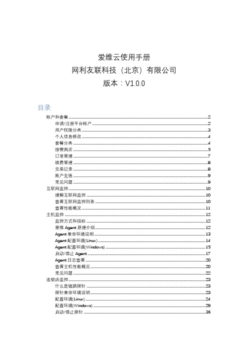
爱维云使用手册网利友联科技(北京)有限公司版本:V1.0.0目录帐户和套餐 (2)申请/注册平台帐户 (2)用户权限分类 (3)个人信息修改 (4)套餐分类 (4)按需购买 (5)订单管理 (7)续费管理 (8)交易记录 (8)账户充值 (9)常见问题 (9)互联网监控 (10)理解互联网监控 (10)查看互联网监控列表 (10)查看性能概况 (11)主机监控 (12)监控方式和指标 (12)爱维Agent原理介绍 (12)Agent兼容环境说明 (13)Agent配置环境(Linux) (14)Agent配置环境(Windows) (15)启动/停止Agent (17)Agent日志查看 (20)查看主机性能概况 (20)常见问题 (22)连锁店监控 (23)什么是链路探针 (23)探针兼容环境说明 (23)配置环境(Linux) (24)配置环境(Windows) (29)启动/停止探针 (36)探针日志查看 (39)查看链路探针列表 (39)添加监控 (40)批量导入 (44)查看监控设备性能概况 (45)采集时间表 (46)内网监控 (48)监控方式与监控内容 (48)爱维内网工具下载 (48)兼容环境说明 (49)安装说明(Linux) (49)安装说明(Windows) (52)启动/停止内网监控工具 (56)登录爱维内网工具 (57)操作手册下载 (58)业务视图 (59)理解业务视图 (59)查看业务趋势 (59)查看业务视图 (60)告警管理 (61)告警状态说明 (61)告警列表 (62)告警通知设置 (63)微信告警 (64)通过url发送告警 (67)数据源 (69)创建数据源 (69)zabbix接入 (70)成员/成员组 (75)报告管理 (76)邮件报告 (76)帐户和套餐申请/注册平台帐户可申请注册的帐户类型系统平台支持个人用户的注册,及服务商用户的申请个人用户注册您可以点击注册按钮后,点击个人用户注册,提交表单后,会向您的注册邮箱发送激活链接,激活后即可登录系统平台官网。
BTE Run 用户操作手册说明书

BTE Run 用户操作手册版本v2.0.1目录1.使用说明 (1)2.运行环境 (2)2.1软硬件运行环境 (2)1)软件运行环境: (2)2)硬件运行环境: (2)3.测试环境搭建 (3)3.1仪表热机 (3)3.2通讯方式 (3)4.用户交互界面 (3)4.1连接仪表 (3)1)打开软件: (3)2)选择连接方式: (4)3)通讯方式: (5)4)仪表连接: (5)4.2配置参数 (7)1)配置测试协议: (7)2)配置链路模式: (9)3)选择测试项目: (12)4)参数设置: (14)4.3开始测试 (16)4.4结果查看 (17)4.5CW测试 (18)1)CW测试参数配置: (18)2)CW测试: (18)4.6Power Control (19)1)Power Control参数配置及测试: (19)4.7RSSI (2)1)RSSI参数配置及测试: (2)1.使用说明欢迎您使用中承BTE Run客户端软件,本软件搭配BTE信令综合测试仪使用。
本手册介绍了软件的各种功能、使用方法和注意事项。
使用BTE Run客户端软件前,请先仔细阅读本手册。
本软件支持经典蓝牙(BR/EDR)协议测试,支持低功耗蓝牙(BLE 4.2/ 5.0/ 5.1/ 5.2)协议测试,测试项如表1-1所示:表1-1BTE测试项目表TRM-LE/CA/06/C Carrier Frequency Offset&DriftRCV-LE/CA/01/C Receiver SensitivityRCV-LE/CA/06/C Maximum Input Signal LevelRCV-LE/CA/07/C PER Report Integrity表1-12.运行环境2.1软硬件运行环境1)软件运行环境:软件控制平台(上位机),包括PC机或笔记本电脑,需要满足以下要求:系统:Windows7/Windows8/Windows1064bitCPU:Pentium(奔腾)Ⅱ及以上内存:至少256MB及以上硬盘:需预留20GB屏幕分辨率:1024*768及以上2)硬件运行环境:搭配深圳市中承科技有限公司的BTE系列BTE信令综合测试仪使用,装有该软件的软件控制平台使用以太网与仪器连接通信。
v5.0操作手册

目录系统简介 (1)一.功能简介 (2)11录像功能 (2)12视频显示 (2)13报警功能 (2)14控制功能 (3)15管理功能 (3)16日志 (3)17电子地图 (3)28网络功能 (4)二.使用说明 (4)21系统初级使用说明 (4)22系统高级使用说明 (13)22.5电子地图 (19)三.客户端使用说明 (21)31软件介绍 (21)四.运行操作: (21)41客户端的配置 (22)42客户端日志的管理 (25)五.硬件 (28)51硬件安装 (28)52系统主机外接设备连接图 (29)53联动报警的实现 (29)54解码器列表 (30)结束语 (31)系统简介V5.0系列数字监控系统是当今多媒体、图像处理、计算机等各项最新技术高度结合的产品。
V5.0系列数字监控系统以计算机为中心,图像数字处理为基础,实现图像监视系统的小型化、高清晰度化、自动化和网络化。
给图像监视工程提供了更优的性能、更灵活的系统组建、更好的系统管理,是图像监视系统从模拟到数字的一个质的飞跃。
它利用最新的图像数字处理技术将模拟视、音频信号转化为数字信号,在计算机显示器上实时显示1—36路以上活动图像的同时,在压缩时将各路视、音频信号分别存储于计算机硬盘内,在计算机上实现信号的监视、记录、回放。
它对视、音频信号采用MPEG-4编码,完全动态码流,使相同质量的录像资料保存时占用更小的空间。
本系统软件支持MPEG1、MPEG2、MPEG4、H.264、D1等算法的程序应用,按硬件的配置,可以满足图像录像质量720×576、1024×768分辨率的要求,而且具完全实时效果,并最大限度地实现了网络传输无极限扩展功能,IE浏览与数据传送等强大功能。
所以它可以应用在银行、电力、电信、交通、军队、智能小区、商业场所、公检法机关,医疗教育系统等领域。
一.功能简介11录像功能1.1.1最大视频/音频处理能力监视和记录帧数 25帧/秒/路摄像机输入 1-36路输入,1V峰值电平,75欧姆BNC端口视频信号格式 PAL/NTSC ,彩色、黑白图像压缩 MPEG-4/D1、像数720×576、352×2881.1.2录像激活方式方式一:预约方式,在事先设定好的录像时间内进行录像,录像时间可按照一周的每一天的每一小时进行设置。
NCV5权限管理使用手册

NCV5.0权限管理应用手册 概述NCV5.0权限管理与之前版本最大的区别在于在权限管理中引入了“角色”概念。
先规划好各种角色并分配权限,再将用户与角色关联起来,将角色作为桥梁把“用户”和“权限”连接起来。
换句话说就是:通过规划好各种角色先将用户分类,再为各类用户分配权限。
NCV5.0版本权限管理和之前版本权限管理相比,另外一个重要的特性就是对用户、角色以及权限实行集中制管理。
在集团或者上级公司能够对下级公司用户、角色的创建以及权限的分配实行完全的管理。
权限管理应用手册分为两个部分,一部分是界面的使用说明,另一部分是流程的示例第一部分:界面使用说明在这一部分中我们主要介绍权限管理中参数的设置以及权限管理模块下各个节点的使用。
1资源权限控制1.1界面及功能概述资源权限控制界面用来为当前登录公司以及当前登录公司的下属公司启用按钮权限控制和数据权限控制。
NC系统中的权限由三个部分构成,分别为功能权限、数据权限和按钮权限。
功能权限是指节点的查看和打开的权限;数据权限是指档案的参照权限,而按钮权限是只指各个界面上按钮的查看和使用权限。
如果不启用权限控制,则不需要分配权限,系统默认角色具有所有权限;启用权限控制后,可以为具体的角色分配具体的权限。
NCV5.0系统默认启用了功能权限控制,且该设置不可修改;数据权限和按钮权限的权限控制默认为不启用状态,但可在本界面对设置进行修改。
资源权限控制的界面如图1.1.1所示。
表头的公司项中默认显示当前登录的公司,可以通过公司的参照选择不同的公司,为其进行资源权限控制的设置。
界面左侧的资源列表中显示的是NC系统中可以启用权限控制的资源,包括按钮和各个可以启用数据权限控制的档案。
选中了某一个资源后,界面右侧会对应显示出当前登录公司以及当前登录公司下属公司能够启用该资源权限控制的组织,这种组织有可能是公司也有可能是主体帐簿,由选择的资源决定。
图1.1.1资源权限控制界面1.2设置权限控制1.2.1选择需要设置权限控制的公司表头有公司的参照,点开参照,能够参照到当前登录公司以及当前登录公司的下属公司(如图1.2.1.1),选择要设置权限控制的公司即可。
英飞拓监控系统操作手册
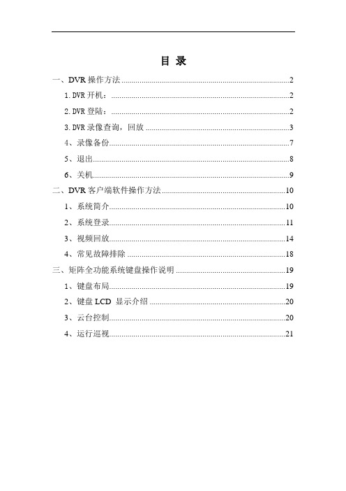
目录一、DVR操作方法 (2)1.DVR开机: (2)2.DVR登陆: (2)3.DVR录像查询,回放 (3)4、录像备份 (7)5、退出 (8)6、关机 (9)二、DVR客户端软件操作方法 (10)1、系统简介 (10)2、系统登录 (11)3、视频回放 (14)4、常见故障排除 (18)三、矩阵全功能系统键盘操作说明 (19)1、键盘布局 (19)2、键盘LCD 显示介绍 (20)3、云台控制 (20)4、运行巡视 (21)一、DVR操作方法1.DVR开机:插上电源线,按下后面板的电源开关,电源指示灯亮,录像机开机,开机后视频输出默认为多画面输出模式,若开机启动时间在录像设定时间内,系统将自动启动定时录像功能,相应通道录像指示灯亮,系统正常工作。
2.DVR登陆:系统正常启动后,设备启动后,通过【MENU】键进入菜单界面,默认弹出用户登录窗口。
如下图:设备出厂时,默认管理员用户名称为“admin”,密码为“12345678”,默认语言为中文。
请注意:进行恢复出厂设置操作以后,语言恢复为英语。
操作步骤如下:第一步:按【ENT】键将用户名下拉列表展开,移动光标选择登录用户名,按【ENT】键确认;第二步:将光标移至密码编辑框,按【ENT】键进入编辑状态,通过前面板数字键即可输入密码,密码输入完毕之后按【ENT】键确认即可登录。
若要取消登录,选中“取消”按钮,按【ENT】确认取消操作。
注:在密码输入过程中若某位密码输入错误,可按【IRIS+】键取消上次输入。
若用户或密码错误,会弹出一个用户名或密码错误的提示对话框,按【ENT】键确认之后,光标重新定位到“登录”按钮处,按上面用户登录操作步骤重新登录。
成功登录后,监视器将显示系统主菜单界面,如图3.DVR录像查询,回放进入回放搜索界面在预览画面模式下,可通过面板的【PLAY】键打开“录像搜索”界面,或者通过进入一级菜单“录像回放”进入,如图所示:2.回放搜索操作选择录像文件搜索条件,如:通道,类型,时间范围,设置完毕后选择“搜索”按钮,通过面板【ENT】键确认进行搜索。
zSecure Admin and Audit for RACF 用户参考手册说明书

zSecure Admin and Audit for RACF User Reference ManualIBMii zSecure Admin and Audit for RACF User Reference ManualContentszSecure Admin and Audit for RACF UserReference Manual (1)iiiiv zSecure Admin and Audit for RACF User Reference ManualzSecure Admin and Audit for RACF User Reference ManualThis chapter lists the documentation updates for zSecure Admin and Audit for RACF User Reference Manual as a result of the zSecure CICS TS 5.5 currency support PTF.In Chapter. Resource reports for z/OS, several panels were updated.In the CICS Regions selection panel, you can select advanced selection criteria.When you select Region security settings , two panels are displayed in sequence:1.The first panel is used for selection criteria that compare against a specifiedvalue:2.The second panel is used for flag fields:In the Select region attributes section of the CICS Regions attributes panel, the Propagation controlled field was added .In the CICS ®Region detailed display report panel, the following sections were updated:v Region identification v SAF protection settingsFigure 1. CICS Regions security settings selection panel - part 1Figure 2. CICS Regions security settings selection panel - part 21|||||||v SAF protection extentFigure 3. CICS region detailed display report2zSecure Admin and Audit for RACF User Reference Manual|||||||||||||。
CSR操作手册

CSR操作手册一、前言 (3)二、登录操作 (3)1.功能说明 (3)2.界面操作说明 (3)三、系统设置 (3)1.功能说明 (3)2.界面操作说明: (4)四、来电弹屏 (5)1.功能说明 (5)2.界面操作说明 (5)五、电话薄 (6)1.功能说明 (6)2.界面操作说明 (6)六、客户资料 (7)1.功能说明 (7)2.界面操作说明 (7)七、客户管理 (10)1.功能说明 (10)2.界面操作说明 (10)八、新增客户 (10)1.功能说明 (10)2.界面操作说明 (10)九、客户编辑 (11)1.功能说明 (11)2.界面操作说明 (12)十、客户管理的历史诉求 (12)1.功能说明 (12)2.界面操作说明 (13)十一、个人的历史诉求管理 (13)1.功能说明 (13)2.界面操作说明 (14)十二、个人历史诉求跟踪 (14)1.功能说明 (14)2.界面操作说明 (15)十三、客户查询 (15)1.功能说明 (15)2.界面操作说明 (16)十四、诉求管理 (16)1.功能说明 (16)2.界面操作说明 (17)十五、历史诉求查询 (17)1.功能说明 (17)2.界面操作说明 (17)十六、历史诉求跟踪 (18)1.功能说明 (18)2.界面操作说明 (19)十七、提醒管理 (19)1.功能说明 (19)2.界面操作说明 (20)十八、提醒界面 (20)1.功能说明 (20)2.界面操作说明 (20)十九、坐席监控 (21)1.功能说明 (21)2.界面操作说明 (21)二十、参数管理 (23)1.功能说明 (23)2.界面操作说明 (23)二十一、录音管理 (24)1.功能说明 (24)2.界面操作说明 (25)二十二、音频导出 (26)1.功能说明 (26)2.界面操作说明 (26)二十三、软电话 (27)1.功能说明 (27)2.界面操作说明 (27)二十四、主界面操作说明 (28)1.界面 (28)2.界面功能说明 (28)一、前言Quick CSR是基于Quick Call呼叫中心系统的客户端控制软件。
ezEIP管理员手册

合肥万户网络技术有限公司ezEIP网站后台管理员册引言尊敬的客户:你好!欢迎使用万户网络技术有限责任公司开发的网站信息管理系统。
为了让您在使用本网站信息管理系统过程中尽快上手,使得本网站信息管理系统尽早的发挥其在网站信息管理中的作用,请您仔细阅读这本管理员操作手册,在使用过程中按照相关章节的程序进行各项操作。
如果您发现本手册中有错误之处、产品运行不正确,或者您对本手册有任何疑问和建议,请与万户网络技术有限公司联系,您的意见将是我们作版本修订的重要依据。
联系方法为:●电话:2887232●传真●Email:●网址:编写目的本管理员操作手册主要包括引言、网站管理和注意事项等三部分内容。
详细介绍了网站信息的后台管理的具体操作方法和步骤。
本操作手册可以作为管理系统操作人员的培训资料,也可在日常管理操作中作为参考。
本操作手册为通用性用书,具体项目中的功能模块可能与本手册有所出入,有不清楚的地方请与项目经理联系。
网站管理信息管理系统的管理包括:直接在服务器上或者通过FTP工具进行的远程的文件管理;和通过访问网站后台进行的对网站信息的远程web管理两大部分操作:后台系统登录网站信息发布后台是通过访问互联网网址后台,超级管理员输入用户名及密码后即可登录该系统。
其他人员想进入系统必须由超级管理员分配帐号方可。
网站后台管理系统登录界面通过身份验证,进入后台维护界面:万户网络网站后台管理系统管理界面◆栏目的管理➢一级栏目的管理点击一级栏目管理,进入一级栏目管理界面有小类说明底下还可以建子栏目,点击将点击可以修改栏点击进入一有小类和无小类之间可以变换。
单击“无小类”会变为“有小类”;同样的单击“有小类”会变为“无小类”。
显示方式有单篇和列表两种可供选择,单击“单篇”显示方式会变为“列表”;同样的单击“列表”显示方式会变为“单篇”。
如果显示方式为“单篇”,则前台会以单篇图文显示内容;如果显示方式为“列表”,则前台以列表形式显示标题,点击标题可以查看具体的内容。
BTL5-A C E1_-M-_ _ _ _-SF-F_ _ 用户手册说明书

BTL5-A/C/E1_-M-_ _ _ _-SF-F_ _User's Guideenglish1 41.1 4Validity1.2 4Symbols and conventionsScope of delivery1.3 41.4 4Approvals and markingsAbbreviations1.5 42 52.1 5Intended use2.2 5General safety notes for the position measuring system2.3 5Meaning of the warnings2.4 5Disposal3 6Construction3.1 63.2 6Function4 7Installing the transducer4.1 74.2 9Electrical connection4.3 9Shielding and cable routing5 015.1 0Starting up the system 1Operating notes 15.2 06 116.1 1Accuracy 1Ambient conditions 16.2 16.3 1Supply voltage (external) 16.4 1Outputs 16.5 1Dimensions, weights 17 217.1 float 12BTL-S-3112-4ZTri-clamp BAM MC-XA-006-D38 17.2 27.3 2Seal BAM SE-XA-002-D38 17.4 2Welded port AD-XA-003-D38 18 319 419.1 4Converting units of length 19.2 4Part label 1english34englishValidity1.1This guide describes the construction, function and setting options for the BTL5 Micropulse Transducer with analog interface. It applies to the typesBTL5-A/C/E1_-M_ _ _ _-SF-F_ _ (see Ordering code on page 13).The guide is intended for qualified technical personnel. Read this guide before installing and operating the transducer.Symbols and conventions1.2 Individual handling instructions are indicated by a preceding triangle.Handling instruction 1►Handling sequences are numbered consecutively:Handling instruction 11. Handling instruction 22. Note, tipThis symbol indicates general notes.Scope of delivery1.3BTL5 transducer –Condensed guide–Floats must be ordered separately (see Accessories, page 12).Approvals and markings1.43-A sanitary standard no. 74-03:This product has authorization number 1486 and only corresponds to thespecifications from 3-A SSI Inc. if used in conjunction with a BTL-S-3112-4Z float and the cotter pin included in the scope of delivery for the float.UL approval File no.E227256US patent 5 923 164The US patent was awarded in connection with this product.The CE Mark verifies that our products meet the requirements of EU Directive 2004/108/EC (EMC Directive)entsprechen.The transducer meets the requirements of the following generic standards:EN 61000-6-2 (noise immunity) –EN 61000-6-4 (emission) –Emission tests:RF emission–EN 55016-2-3Group 1,Class A and BNoise immunity tests:Static electricity (ESD)–EN 61000-4-2Severity level 3Electromagnetic fields (RFI)–EN 61000-4-3Severity level 3Electrical fast transients (burst)–EN 61000-4-4Severity level 3Surge–EN 61000-4-5Severity level 2Conducted interference induced by–high-frequency fieldsEN 61000-4-6Severity level 3Magnetic fields–EN 61000-4-8Severity level 4More detailed information on the guidelines, approvals, and standards is included in the declaration of conformity.Abbreviations1.53-A SSI 3-A Sanitary Standards, IncorporatedEHEDG European Hygienic Engineering & Design Group FDAU.S. Food and Drug Administration1Intended use2.1The BTL5 Micropulse Transducer, together with a machine controller (e.g. PLC), comprises a displacement measurement system. It is intended to be installed into a machine or system. Flawless function in accordance with the specifications in the technical data is ensured only when using original BALLUFF accessories, and use of any other components will void the warranty.NoteCompliance with the 3-A SSI specifications isonly attained through the use of thecomponents listed under accessories(see page 12).Opening the transducer or non-approved use are not permitted and will result in the loss of warranty and liability claims against the manufacturer.General safety notes for the position2.2measuring systemInstallation and startup may only be performed by trained specialists with basic electrical knowledge. Specialists are those who can recognize possible hazards and institute the appropriate safety measures due to their professional training, knowledge, and experience, as well as their understanding of the relevant regulations pertaining to the work to be done.The operator is responsible for ensuring that local safety regulations are observed.In particular, the operator must take steps to ensure that a defect in the position measuring system will not result in hazards to persons or equipment.If defects and unresolvable faults occur in the transducer, take it out of service and secure against unauthorized use.Meaning of the warnings2.3Always observe the warnings in these instructions and the measures described to avoid hazards.The warnings used here contain various signal words and are structured as follows:SIGNAL WORDHazard type and sourceConsequences if not complied withMeasures to avoid hazardsfThe individual signal words mean:Disposal2.4Observe the national regulations for disposal.25english1) Not included Fig. 3-1: BTL5...-SF-F... transducer, constructionConstruction3.1Electrical connection:The electrical connection is made via a cable and permanent (see Ordering code onpage 13).BTL housing:Stainless steel housing containing the processing electronics.Float: Defines the position to be measured on the waveguide. Floats must be ordered separately (see Accessories on page 12).Nominal length: Defines the travel/length range available. Rods with various nominal stroke lengths from 70 mm to 2500 mm are available depending on the model.Function3.2The BTL5 transducer contains the waveguide which is protected by an outer stainless steel tube (rod). A float is moved along the waveguide. This float also rises and falls with the level of the liquid whose position is to be determined.The float defines the position to be measured on the waveguide.An internally generated INIT pulse interacts with the magnetic field of the float to generate a torsional wave in the waveguide which propagates at ultrasonic speed.The component of the torsional wave which arrives at the end of the waveguide is absorbed in the damping zone to prevent reflection. The component of the torsional wave which arrives at the beginning of the waveguide is converted by a coil into an electrical signal. The travel time of the wave is used to calculate the position. Depending on the version, this information is made available as a voltage or current with rising or falling gradient.36english 7english Installing the transducer4.1For holding the transducer and float we recommend non-magnetizable material.Installing the floatInstall the float (accessory) taking the orientation into1. account (raised markings on top, see Figures 4-1 and 4-2).Secure the float using the cotter pin provided in the2. scope of delivery, without placing any mechanical loads on the outer rod. Guide the cotter pin through the holeuntil it engages (see Figure 4-3).Fig. 4-1:Installing the floatFig. 4-2: Raised markings on floatInserting the cotter pinFig. 4-3: 48englishInstalling the transducerNOTICEInterference in functionImproper installation can compromise the function of the transducer and result in increased wear.Only vertical mounting is permitted!f The flange surface of the transducer must make fullf contact with the mounting surface and be perfectly sealed through the use of a seal and tri-clamp.Mounting must be done in a manner where the outerf rod cannot touch the container wall. Deflection of the outer rod to the side, e.g. through flow currents, must be prevented by suitable brackets.Insert suitable seal (see Figure 4-4).1. Place the transducer on the mounting surface, so it2. makes full contact and perfectly seals the hole (see Figure 4-5).Fasten the transducer with a 1 1/2" tri-clamp (see3.Figure 4-6).Fig. 4-4: Inserting the sealMounting surfaceFig. 4-5:Installing the BTLFig. 4-6: Fastening the BTL with a 1 1/2" tri-clamp4 9english Electrical connection4.2The electrical connection is permanent and made using a cable (F_ _). The connection assignments depend on therespective model (see Tab. 4-1).Connection assignmentsTab. 4-1: Shielding and cable routing4.3 Defined ground!The transducer and the control cabinet must be at the same ground potential.ShieldingTo ensure electromagnetic compatibility (EMC), observe the following:Connect the transducer and controller using a shielded–cable.Shielding: Copper filament braided, at least 85% coverage.On the transducer side, the cable shielding is–connected to the housing. Ground the cable shielding on the controller side (connect with the protection ground).Magnetic fieldsThe transducer system is a magnetostrictive system.Ensure that there is sufficient distance between thetransducer and between the holding cylinder and strong, external magnetic fields.4Cable routingDo not route the cable between the transducer, controller, and power supply near high voltage cables (inductive straynoise is possible).Cable lengthTab. 4-2: 1)Prerequisite: Construction, shielding and routing preclude the effect of any external noise fields.Bending radius for fixed cableThe bending radius for a fixed cable must be at least five times the cable diameter.55.1Starting up the system Array Check connections for tightness and correct polarity.1.Replace damaged connections.Turn on the system.2.Check measured values (especially after replacing the3.transducer or after repair by the manufacturer).Operating notes5.2–Check the function of the transducer and all associatedcomponents on a regular basis.Observe the directives of the FDA und 3-A SSI for –monitoring hygiene and cleaning of the device, as wellas the instructions for operation and maintenance ofthe entire system.–It is possible to clean the device during the process.Take the position measuring system out of operation –whenever there is a malfunction.Secure the system against unauthorized use.–10englishAccuracy6.1The specifications are typical values at 24 V DC and room temperature, with a nominal length of 500 mm in conjunction with the BTL-S-3112-4Z float.The BTL is ready immediately, full accuracy after warm-up phase.ReproducibilityCurrent0.6 µAMinimum0.05 mmSampling rate fStandard500 HzNon-linearity at≤ 500 mm±250 µm> 500 mm±0.05% FS Temperature coefficient(nominal length = 500 mm,float in the middle ofmeasuring range)≤ 40 ppm/KAmbient conditions6.2Operating temperature1)−10°C to +85°CProcess temperature2)−20°C to +130°C Storage temperature−20°C to +100°C Relative humidity< 90%, non-condensing Pressure rating (BTL outerrod)≤ 300 barPressure rating (limited byfloat)≤ 4 barDegree of protection perIEC 60529 (when attached)IP 671) Operating temperature: maximum permissible operating temperature at the BTL housing.2) Process temperature: maximum permissible temperature of the rod below the flange (with contact with the media).Certain production processes require e.g. sterilization at 120°C–130°C for 0.5–1 hour.Supply voltage (external)6.3Voltage, stabilizedBTL5-A/C/E1...20 to 28 V DCRipple≤ 0.5 V ppCurrent draw≤ 150 mAInrush current≤ 3 A/0.5 msReverse polarity protection InstalledOvervoltage protection36 VDielectric strength GND to housing 500 V DCOutputs6.4BTL5-A...Output voltage0 to10 V and 10 to 0 VLoad current≤ 5 mABTL5-C...Output current0 to 20 mA and 20 to 0 mALoad resistance≤ 500 OhmsBTL5-E...Output current 4 to 20 mA and 20 to 4 mALoad resistance≤ 500 OhmsDimensions, weights6.5Diameter of outer rod10.2 mmNominal length≤ 2500 mmWeight (depends on length)Approx. 2 kg/mHousing material Stainless steel 1.4404Outer rod material Stainless steel 1.4404Outer rod wall thickness 2 mmYoung's modulus Approx. 200 kN/mm2Housing mounting 1 1/2" tri-clamp as perSSI 3A standard 74-03 andseal BAM SE-XA-002-D38(see accessories onpage 12)611english12englishAccessories are not included in the scope of delivery and must be ordered separately.Float BTL-S-3112-4Z7.1Ø 31Ø 11.769ImpressionFig. 7-1: Float BTL-S-3112-4ZWeight 30 gHousing 1.4404 stainless steel Electrolytic polishing Operating temperature−20°C to 130°CIncluded in the scope of delivery for the float:Float–Instructions–Cotter pin (spring pin 2x30)–Fig. 7-2: Spring pin 2x307Tri-clamp BAM MC-XA-006-D387.2Fig. 7-3:BAM MC-XA-006-D38Material USA ASTM 316 (1.4401)Seal BAM SE-XA-002-D387.3Fig. 7-4: BAM SE-XA-002-D38Material PolytetrafluorethyleneWelded port AD-XA-003-D387.4Fig. 7-5: BAM AD-XA-003-D38MaterialSt. no. w. 1.4435 BN2 (Fe < 0.5%) acc. to EB 100888BTL5 - E 1 7 - M0500 - SF - F05 Micropulse transducerInterface:A = Analog interface, voltage output 0 to 10 VC = Analog interface, current output 0 to 20 mAE = Analog interface, current output 4 to 20 mASupply voltage:1 = 24 V DCOutput gradient:0 = Rising (C_0 = 0 to 20 mA, E_0 = 4 to 20 mA)1 = Rising + falling (A_1 = 10 to 0 V and 0 to 10 V)7 = Falling (C_7 = 20 to 0 mA, E_7 = 20 to 4 mA)Nominal stroke (4-digit):M0500 = Metric specification in mm, nominal length 500 mmConstruction:SF = Plug-in flangeFastening: 1 1/2" tri-clampElectrical connection:F05 = Teflon cable, radial outlet 5 menglish13Converting units of length 9.11 mm = 0.0393700787 inchesConversion table mm to inches Tab. 9-1:1 inch = 25.4 mmConversion table inches to mm Tab. 9-2:Part label9.2Fig. 9-1:TypeSerial number BTL5 part label9Ordering code14english。
MyPBX U5系列管理员配置手册说明书

MyPBX U5系列管理员配置手册版本14.18.0.22厦门朗视信息科技有限公司目录1. 简介 (5)1.1 功能特点 (5)1.2 硬件规格 (6)1.2.1 外观 (6)2. 系统设置 (7)2.1 连接示意图 (7)2.2 以太网的连接 (8)2.3 电源的连接 (9)3 管理员登陆 (10)4 状态 (12)4.1 中继状态 (12)4.1.1 分机状态 (12)4.1.2 中继状态 (13)4.2 系统状态 (15)4.2.1 系统信息 (15)4.2.2 网络状态 (16)5 系统 (17)5.1 网络参数 (17)5.1.1 LAN设置 (17)5.1.2 WAN设置 (18)5.1.3 DHCP服务器 (19)5.1.4 VLAN设置 (19)5.1.5 VPN设置 (21)5.1.6 DDNS设置 (22)5.1.7 静态路由设置 (23)5.2 防火墙设置 (24)5.2.1 防火墙规则 (25)5.2.2 IP 黑名单 (27)5.3 系统参数 (29)5.3.1 密码设置 (29)5.3.2 日期与时间 (30)5.3.3 固件升级 (31)5.3.4 备份与还原 (31)5.3.5 重置与重启 (31)5.3.6 双机热备 (32)5.3.7 AMI 设置 (33)5.3.8 警报设置 (34)5.3.9 数据库授权 (37)5.3.10 安全中心 (38)5.4 .................................................................................................................... 存储设备管理 (39)5.4.1 硬盘管理 (39)5.4.2 自动备份 (39)6 PBX (42)6.1 分机 (42)6.1.1 FXS/VoIP 分机 (42)6.1.2 话机配置 (52)6.2 中继 (60)6.2.1 物理中继 (60)6.2.2 VoIP 中继 (69)6.3 呼出设置 (76)6.3.1 呼出路由 (76)6.3.2 速拨设置 (79)6.4 呼入设置 (80)6.4.1 自动话务员(IVR) (80)6.4.2 响铃组 (82)6.4.3 呼叫队列 (84)6.4.4 会议室 (88)6.4.5 呼入路由 (89)6.5 语音文件设置 (94)6.5.1 自定义提示音 (94)6.5.2 等待音乐 (95)6.5.3 系统提示音设置 (96)6.6 基本设置 (97)6.6.1 常规设定 (97)6.6.2 办公时间设置 (99)6.6.3 特征码 (100)6.6.4 语音信箱设置 (103)6.7 高级设置 (106)6.7.1 SIP设置 (106)6.7.2 IAX设置 (111)6.7.3 黑名单 (111)6.7.4 回拨设置 (112)6.7.5 DNIS 设置 (114)6.7.6 DISA (114)6.7.7 PIN User 设置 (116)6.7.8 广播组与对讲组 (117)6.7.9 短信设置 (118)6.7.10 证书 (120)7 报告 (122)7.1 通话记录 (122)7.2 系统日志 (123)8 插件 (124)8.1 MyPBX客户端 (124)8.2 计费系统 (124)8.3 酒店模块 (125)9 退出 (125)10 MyPBX U5XX实际应用 (126)10.1 呼出 (126)10.1.1 通过E1中继呼出 (126)10.1.2 通过SIP中继呼出 (127)10.2 呼入 (130)10.2.1 呼入到自动话务员 (130)附录A 常见问题 (132)附录B MyPBX U5系列安全性配置 (133)1. 设置网页界面访问安全性 (133)1.1 修改默认的网页访问端口 (133)1.2 修改默认的网页登录密码 (133)2. 设置SSH访问安全性 (134)2.1 无需要时停用SSH访问 (134)2.2 修改默认的SSH访问密码 (134)3. 设置分机的安全性 (136)3.1 修改默认的SIP访问端口 (136)3.2 设置匿名认证的安全性 (136)3.3 设置远程注册的安全性 (137)3.4 设置分机的密码和授权IP地址 (137)4. 设置防火墙 (138)4.1 启用防火墙 (139)4.2 设置允许局域网内分机注册的防火墙防御规则 (139)5. 警报设置 (146)5.1 IPATTACK (146)5.2 WEBLOGIN (147)附录C 如何配置自动备份 (149)附录D 如何配置NAT (151)附录E 如何使用Auto Provision (153)附录F 如何配置特色铃声 (155)附录G 如何使用邮件到短信功能 (158)附录H 如何使用DID (160)MyPBX U5系列管理员配置手册1. 简介MyPBX — IP 集团电话MyPBXU5XX是专为企业量身定制的嵌入式电话系统,MyPBXU5XX E1/T1/J1中继(数字中继)和VoIP网络完美的结合在一起,不仅高效的控制了通信成本,同时也确保用户在断电或者网络中断的情况下保持通话不中断,更稳定的使用电话系统。
【精品文档】业务操作手册(北京华大智宝)

【精品文档】业务操作手册(北京华大智宝)E动终端操作手册中国建设银行股份有限公司E终端业务操作手册北京华大智宝电子系统有限公司2010年10月目录第1页E动终端操作手册中国建设银行股份有限公司 ................................................................................................................................ ...... 1 E终端业务操作手册 ................................................................................................................................ ................... 1 第一章关于本操作手册的说明 ..............................................................................................................................5 1.1 使用对象 ................................................................................................................................ ..................... 5 1.2 E动终端硬件操作事项 ...............................................................................................................................5 1.3 E动终端软件操作事项 ...............................................................................................................................5 第二章系统管理 ...................................................................................................................错误~未定义书签。
Leadsec-CVS-V6.0.80.3_U1.0-安全配置核查管理系统-用户手册-V1.0-20141105

4
资产 ................................................................................................................................................................ 41 4.1 4.2 资产管理 .............................................................................................................................................. 41 资产类型 .............................................................................................................................................. 46
6
参考知识 ........................................................................................................................................................52 6.1 6.2 6.2.1 6.2.2 各协议帮助 ...........................................................................................................................................52 知识 ........................................................................................................................................................52
网御上网行为管理Leadsec-C5000完整版标底V5.0
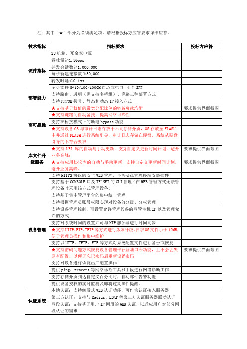
可分组、分用户、分时段设置网址黑名单和白名单
支持网络言论控制:可分组、分用户、分时段审计和控制用户通过BBS、WEBMail、Blog等发送的网络言论
支持IM应用控制:可分组、分用户、分时段封堵和审计用户使用聊天软件的行为信息,包括聊天软件QQ、webQQ、MSN、淘宝旺旺、Skypelk、移动飞信、iChat等常用聊天软件
支持SYN Flood、UPD Flood、ICMP Flood、ARP Flood等攻击防护
★支持IPsec VPN功能
要求提供界面截图
★支持L2TP VPN功能
要求提供界面截图
★支持对特权用户提供免审计Usb-key功能,以解决过度审计的问题
要求提供界面截图
高级网络应用
支持静态路由协议
支持基于源地址和基于接口的策略路由
提供资质证书
具有国家版权局颁发的《计算机软件著作权登记证书》
提供资质证书
公司资质
★要求设备制造商具备工业和信息化部颁发的《计算机信息系统集成资质证书》(壹级)
提供资质证书
★要求设备制造商具备中国信息安全产品测评认证中心颁发的《国家信息安全认证信息安全服务资质证书》(安全工程类二级)
提供资质证书
★具备国家保密局颁发的《涉及国家秘密的计算机信息系统集成资质证书》(甲级)
★支持仅允许使用Usb-key权限管理员对审计日志的单条、应用类别及时间范围进行删除
要求提供界面截图
★支持管理审计内容Usb-key,实现对审计日志的分级分权查阅,即不使用UKEY仅可查看上网行为审计轨迹,使用UKEY可查看所有上网行为审计数据,包括电子邮件内容、发帖内容、聊天内容等
- 1、下载文档前请自行甄别文档内容的完整性,平台不提供额外的编辑、内容补充、找答案等附加服务。
- 2、"仅部分预览"的文档,不可在线预览部分如存在完整性等问题,可反馈申请退款(可完整预览的文档不适用该条件!)。
- 3、如文档侵犯您的权益,请联系客服反馈,我们会尽快为您处理(人工客服工作时间:9:00-18:30)。
BTA IntraSec™
运营保障系统管理员参考手册Ver5.0
北京桥盟创联科技有限公司2010©版权所有保留所有权利
1.系统部署与安装 (3)
1.1.策略服务器的安装与部署 (3)
1.1.1.部署前的准备 (3)
1.1.2.部署方式 (4)
1.1.2.1.只针对内网(Intranet)用户的部署方式 (4)
1.1.2.2.针对内网(Intranet)和互联网(Internet)用户的部署方式 (4)
1.1.3.双机互备 (5)
1.2.客户端的安装 (5)
1.2.1.适用的操作系统及硬件环境 (5)
1.2.2.客户端的安装 (6)
1.2.2.1.替换客户端的身份 (7)
1.2.2.2.三种安装方式 (8)
1.2.3.客户端的卸载 (10)
2.系统配置 (10)
3.基本组织管理方式 (11)
4.网络接入策略设置 (11)
5.主机完整性策略设置 (11)
6.行为管理策略设置 (11)
7.审计策略设置 (11)
8.其它策略设置 (11)
9.报表系统 (11)
10.常见问题及解决办法 (11)
1.系统部署与安装
1.1.策略服务器的安装与部署
1.1.1.部署前的准备
在部署BTA IntraSec™运营保障系统以前,请检查并确认产品包装箱内是否包含以下设备或资料:
在将BTA 系统策略服务器部署到网络中之前,请确认已经准备好以下资料信息:
●从开发商那里获得的产品使用授权;
●为策略服务器分配的IP地址(至少需要一个内网的IP地址,如果您购买了两台服务器
做成双机互备的方式,则需要分配两个不同的内网IP地址;此外,如果您单位的员工需要通过互联网访问策略服务器,还需要为服务器分配一个公网的IP地址,以便通过NAT或者端口映射方式映射到策略服务器的内网IP地址上);
●本单位的部门及终端资料,包含部门名称及终端的使用者,以便稍后将这些信息导入到
服务器上,生成客户端的安装序列号。
1.1.
2.部署方式
1.1.
2.1.只针对内网(Intranet)用户的部署方式
BTA 策略服务器属于旁路设备,不需要串联在网络通信的路由通道中。
一般情况下,建议将BTA策略服务器放置在内网的服务器区域,并且为服务器分配一个内网的IP地址,以便内网用户能够直接通过此IP地址访问策略服务器,如下面的示意图所示:
1.1.
2.2.针对内网(Intranet)和互联网(Internet)用户的部署方式
如果需要为内网及外网用户都安装BTA桌面安全助理客户端程序,就需要保证外网用户能够通过互联网IP地址访问BTA策略服务器。
一般情况下,您单位至少需要拥有一个公网的IP地址,并通过NAT方式将该地址映射到策略服务器的内网IP地址上。
BTA客户端程序与策略服务器通信协议为标准的HTTP协议(TCP 80),因此,除了必要的地址映射以外,还建议您通过防火墙对内网的BTA策略服务器进行保护,只开放HTTP 协议的访问即可。
除此以外,您还要在策略服务器的管理员操作界面对策略服务器的IP地址参数进行配置,详细配置方法参见(1.4服务器的基本配置参数)部分。
1.1.3.双机互备
BTA策略服务器支持双机互备的部署方式,这种情况下,当主策略服务器发生故障时,客户端安全助理程序能够自动登录到另一台服务器上,从而不影响客户端的信息上报与策略下发。
两台服务器之间的数据库内容是同步的。
为了实现策略服务器的双机互备,您需要为两台策略服务器提供两个不同的内网IP地址,部署方式如下图所示:
除此以外,您还要在策略服务器的管理员操作界面对策略服务器的IP地址参数进行配置,详细配置方法参见(1.4服务器的基本配置参数)部分。
一般情况下,采用双机互备方式后,如果您需要继续支持公网用户安装BTA客户端安全助理程序,建议您将公网的IP地址映射到作为主策略服务器的内网IP地址上。
1.2.客户端的安装
1.2.1.适用的操作系统及硬件环境
BTA IntraSec™运营保障系统客户端程序(以下简称BTA客户端)需要安装在以下操作系统上:
●Microsoft Windows 2000 各个版本(暂不支持64位)
●Microsoft Windows XP各个版本(不支持64位)
●Microsoft Windows Server 2003
●Microsoft Vista各个版本(暂不支持64位)
●Microsoft Windows 7 各个版本(暂不支持64位、部分功能不支持)
安装BTA客户端程序需要以下硬件配置需求:
●奔腾1.8G以上CPU
●至少需要128M物理内存
●安装需要约20M磁盘空间,建议剩余磁盘空间不低于100M
1.2.2.客户端的安装
安装BTA客户端所需的安装程序可以从BTA策略服务器上下载,下载方式为HTTP,例如策略服务器的IP地址为10.10.10.1,那么下载安装程序的地址为:http://10.10.10.1。
在安装客户端程序时,有些安全软件会拦截或阻止安装程序的安装过程,如果遇到此种情况,请选择”取消阻止”、“信任此程序”等类似选项,以便安装程序能够继续安装。
1.2.2.1.替换客户端的身份
如果您需要更改已经安装的BTA客户端程序的身份信息,不需要先卸载已经安装的客户端后再次重新安装,只需要已经安装了客户端程序的计算机上运行安装程序即可。
安装程
序运行时,能够检测到先前的客户端安装,并允许您替换已经安装的客户端程序的身份。
1.2.2.2.三种安装方式
与其它常见的应用软件不同,BTA客户端是具有“身份”信息的。
例如,某个客户端的身份是“XXX公司->财务部->会计用机A”。
只有区分了客户端的身份,才能够按照不同部门或者计算机部署不同策略。
可以使用以下三种方式之一安装BTA客户端程序:
●输入序列号安装方式:策略服务器自动为不同的计算机生成唯一的8位数字的安
装序列号,在安装时可以直接输入与计算机身份一致的安装序列号进行安装即可;
●匿名安装方式:采用此种安装方式时,不需要输入安装序列号,直接安装即可。
安
装成功后,策略服务器上自动为将该客户端放置到一个名称为“匿名计算机”的分
类下,稍后管理员可以根据该计算机上报的相关信息进行判别,再将该计算机移动
到正确的分组下;
●通过服务器浏览客户端方式安装:此种安装方式需要管理员权限,管理员通过身份
认证后,可以通过浏览方式选择客户端身份进行客户端的安装。
1.2.3.客户端的卸载
通过“控制面板->添加/删除程序”位置即可卸载客户端程序,在卸载前,需要输入正确的卸载口令。
卸载口令可以在服务器上进行设置。
2.系统配置
2.1.全局配置参数
2.2.模块管理
11
3.基本组织管理方式
4.网络接入策略设置
5.主机完整性策略设置
6.行为管理策略设置
7.审计策略设置
8.其它策略设置
9.报表系统
10.常见问题及解决办法
北京桥盟创联科技有限公司2010©版权所有服务热线:400 610 0362。
