SMC缓冲器RB0604
SMC气动第三册(真空元件)
记号 06 08 10 12 01 02 03
尺寸 ø6 ø8 ø10 ø12 Rc 1 8 Rc 1 4 Rc 3 8
形式 快换接头 快换接头 快换接头 快换接头 螺纹拧入 螺纹拧入 螺纹拧入
表① 连接形式的组合
主体形式 盒型 (内置消声器) 直接配管型 (无消声器) ① ② ③ ① ② ③ SUP 快换接头 快换接头 螺纹拧入 快换接头 快换接头 螺纹拧入 VAC 快换接头 螺纹拧入 螺纹拧入 快换接头 螺纹拧入 螺纹拧入 EXH — — — 快换接头 快换接头 螺纹拧入
页号
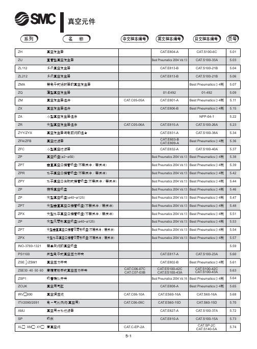
5.01 5.03 5.04 5.06 5.07 5.09 5.11 5.15 5.22 5.23 5.34 5.36 5.37 5.38 5.39 5.42 5.44 5.46 5.47 5.48 5.51 5.53 5.54 5.57 5.59 5.60 5.61 5.63 5.64 5.65 5.68 5.70 5.72 5.73 5.74
注意
1 配管不能是螺旋状。
真空侧和供给侧都不能出现螺旋状配管, 应尽量短而直。 配管容积增 大则响应时间变长。
2 真空发生器排气侧的配管有效截面积应大。
排气一旦节流,真空发生器的性能就变差。
4 吸入流量过大,则真空开关的设定困难。
几 mm大小的小工件, 一旦选定吸入流量过大的真空发生器, 和未吸 着时的真空压力之差太小, 会使真空压力开关的设定变困难, 故要选 定合适的真空发生器。
注意
1 方向控制阀,速度控制阀等相关元件应参见各自样本的注意 事项。
维护
警告
1 要定期对真空过滤器和消声器进行清洗。
过滤器及消声器的孔眼被堵, 真空发生器的性能便降低。 在粉尘多的 场合,应使用处理流量大的真空过滤器。
SMC Air Filter AF10至AF60定制规格说明说明书
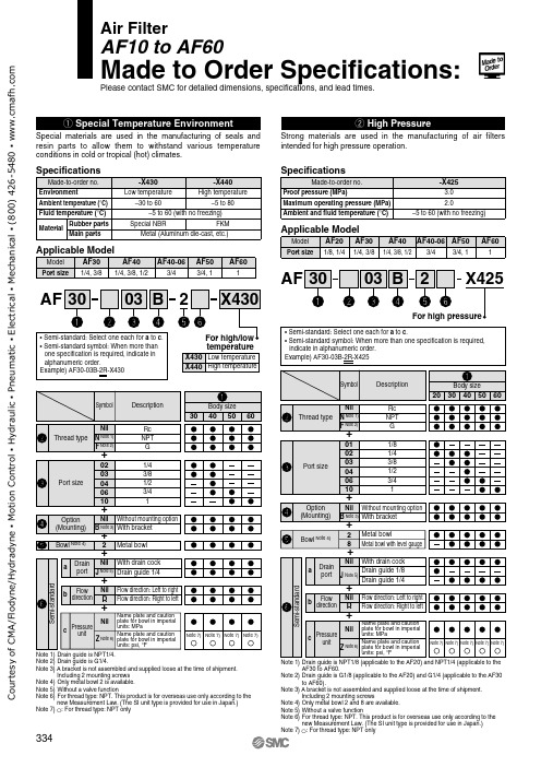
Specifications
Made-to-order no. Proof pressure (MPa) Maximum operating pressure (MPa) Ambient and fluid temperature (°C)
-X425 3.0 2.0
–5 to 60 (with no freezing)
Air Filter
AF10 to AF60
Made to Order Specifications:
Please contact SMC for detailed dimensions, specifications, and lead times.
Courtesy of CMA/Flodyne/Hydradyne ▪ Motion Control ▪ Hydraulic ▪ Pneumatic ▪ Electrical ▪ Mechanical ▪ (800) 426-5480 ▪
Including 2 mounting screws Note 4) Only metal bowl 2 is available. Note 5) Without a valve function Note 6) For thread type: NPT. This product is for overseas use only according to the
new Measurement Law. (The SI unit type is provided for use in Japan.) Note 7) ć: For thread type: NPT only
indicate in alphanumeric order. Example) AF30-03B-2R-X425
SMC系列产品使用说明书
5.4 SMC/HBC、SMC/JA部分回转产品的安装与拆卸方法是:
先将花键接头装到阀杆上,使电动装置二级减速机构的驱动轴位置与阀门所处位置相同。
(此时阀门在某一终端位置最理想)起吊电动装置,使其驱动轴与阀杆上的花键接头对准,同时应对准阀门与电动装置的连接螺孔。使驱动轴与花键接头配合装入,而后用螺栓将阀门与电动装置紧固可靠。
a、型号:该产品型号。
b、最大控制转矩:该产品出厂前调定的最大转矩值(N.m)。
c、输出转速:该产品在单位时间内输出轴的转圈数(r/min)。
d、最大转圈数:该产品位置指示机构指针从0~100%走满刻度情况下输出轴总的转圈数。
e、编号:该产品总序号或本年度产品的序号。
f、合同号:该产品年度订货合同号。根据它可查出产品出厂前的全部情况,便于售后服务。
与G·L·SW的触点信号不同,MDPI的阀位反馈信号是连续的。
(图19)所示为MDPI位置指示机构的结构。从图中可见其传动部分是若干对小模数配换齿轮,该机构对任何口径的阀门均能保证其指针做满刻度指示。
▼关于电动装置的控制器
对于一般控制原理,控制器是与电动装置分离的电气控制部件,它通常设置在控制室内为单独订货产品。
5.7电动装置的工作位置一般无原则要求。但推荐电动机轴线为水平状态,G·L·SW箱罩处于水平或垂直向上、向下状态,以利于产品的润滑、维修及阀位观测。
6.润滑
6.1产品出厂前已注入专用润滑脂,使用中每年应至少检查润滑情况一次,如无异常可继续使用。
6.2电动机轴承的润滑脂一般不必更换或添加。
6.3产品维修后更换润滑脂时应注意其抗氧化性、耐水性、耐热性、防锈性、机械稳定性等,并应注意其抗挤压性,以保证产品的润滑性能和较高的传动效率。
中文四版-SMC样本
20~40
CAT.C04-02A
20~40
CAT.C04-02A
40~100
CAT.C09-03A
32~125
CAT.C05-09B
32~100
CAT.C06-06A
125~300 8~25
CA3T2.C~05-2052B0
20~63 32~100
正确内容
32~100
CAT.C08-04B
12~100
07年8月 06年8月 06年8月 06年8月 06年8月 07年8月
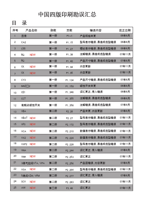
说明:1.中国四版06年1月份正式印刷完成,06年8月份第一次增印,改动10页,07年8月份第二次增印,改动15页, 07年11月第三次增印,改动18页。
2.请注意将将更改信息通知相关客户,订货时予以确认。
执行元件
系列
气缸类型
缸径(mm) 中文样本编号 英文样本编号 日文样本编号 页号
页数 P3.55 P4.25 P4.26
错误内容 可换件型号错误 数值表示错误 型号表示错误、易造成选型错误
P4.34 P4.42
词汇更正、录入错误 型号表示不清、易造成选型错误
P4.64 P4.70
词汇更正、录入错误 追加系列
P4.102 型号表示内容错误
P4.110 型号表示内容错误
P5.09 数值表示错误
标准型气缸
图形符号
CA2系列 ( ~ )
1
1
。
弯
1系列
1
。
。 。
。
型号表示方法
mm
拉杆安装
除A54外 仅A54 BT-04 BT-06 BT-08
参见P.1.357。
正确内容
F
SMC SMC过滤器 (FGE 系列) 说明书
使用说明书SMC过滤器 (FGE 系列)FGESA-10(20) , FGELA-10(20)FGESB-10(20) , FGELB-10(20)FGESC-10(20) , FGELC-10(20)SMC株式会社目 录● 安全上的注意・・・・・・・・・・・・・・・・P2 ● 零件名称及功能・・・・・・・・・・・・・・・P3 ● 系统设计,设置,配管・・・・・・・・・・・・・P4 ● 操作・・・・・・・・・・・・・・・・・・・・P4 ● 产品规格・・・・・・・・・・・・・・・・・・P4 ● 滤芯更换和拆卸 ・・・・・・・・・・・・・・P5 ● 本公司主要营业所一览・・・・・・・・・・・・P8FGES,L系列安全上的注意这里所指的注意事项,记载了FGES,FGEL系列产品应如何安全正确的使用,以防止对您及他人造成损伤。
所有与安全相关的重要内容以及其他安全规则,都必须严格遵守。
注意:误操作时,可能造成人及设备的损伤。
警告:误操作时,可能造成人的死亡或重伤。
警告:误操作时,可能会发生漏液或上盖飞出等危险事故。
请有足够知识和经验系统设计者来判断元件的选型是否合适。
使用条件范围操作上的注意①使用压力不要使用超出范围的压力。
②使用温度不要使用超出范围的温度。
③使用流体・禁止使用于气体。
・不要使用于腐蚀性液体。
・不要使用于会引起密封圈,O形圈以及滤芯膨胀或劣化的流体。
④使用环境・不要在有腐蚀性的环境下使用。
・不要在有振动和物体冲击的环境下使用。
①加压状态下禁止松开V形带。
②V形带正确地安装在指定的位置上。
(请参照第7页)③发生膨胀或劣化等异常的O形圈,请进行更换。
O形圈的更换,请在使用后1年以内,或者有漏液发生时进行。
(更换用O形圈:参照3页表1)④泵起动时,请务必将上部的空气排气口打开,进行排气。
⑤请不要使用变形或螺纹破损的V形带。
(更换用V形带:参照3页表1)注意:为防止滤芯破损,保障滤芯的过滤性能及保养点检的可作业性,请务必遵守以下注意事项。
SMC目录列表
方向控制器4、5通先导式电磁阀1》4通电磁阀/盒式集装式SJ:1.SJ2000系列/CAD,2.SJ3000系列/CAD卖点特长:扁平盒式结构。
省空间:阀宽7.5mm(SJ2000)、10mm(SJ3000)。
SJ2000、SJ3000可混装使用。
采用插座式连接方式,易于增减集装位数和阀的更换。
单电控。
具有4位双3通阀规格。
2》真空节流破坏阀SJ3A6系列卖点特长:内置有2个滑阀。
能够用1个阀来控制真空吸着和破坏。
阀宽10mm(与SJ3000系列相同)。
带有能够调节空气流量的节流阀。
真空侧与破坏侧内置多种可交换的过滤器。
可以与4通电磁阀SJ2000/SJ3000混合使用。
3》5通电磁阀SY:1.SY3000系列2.SY5000系列3. SY7000系列4.SY9000 系列卖点特长:3通阀和5通阀能够混合安装使用。
消耗功率:0.1W (带省电回路)有铝制一体型、DIN导轨式、组合集装型等丰富的集装式类型可供选择。
4》新款5通电磁阀新SY:1.SY3000系列2.SY5000系列卖点特长:阀体宽度不变,流量最多增加80%SY3000宽:10mm、SY5000宽:15mm。
寿命2亿次(金属密封)7000(橡胶密封)插入式金属底板(IP40)/插入式插件连接底板(IP67)底面配管,省空间5》5通电磁阀SV:1.SV10002系列2.SV2000系列3.SV3000系列4.SV4000系列卖点特长:便于实现集装式阀的增连以及规格变更。
单电控。
具有4位双3通阀规格。
6》4、5通电磁阀SYJ1.SYJ3000系列2.SYJ5000系列3.SYJ7000系列卖点特长:3通阀和5通阀能够混合安装使用。
消耗功率:0.1W (带省电回路)7》5通电磁阀/盒式集装式SZSZ3000系列卖点特长:具有便于实现阀的交换的盒式结构。
带有开关的阀使得维护时更安全。
采用扁平盒式结构更加节省空间。
8》大型5通电磁阀VP1.VP4□50系列2.VP4□70系列卖点特长:用于大型缸驱动。
SMC调压阀

Reverse Flow Func.
Nil K
R ev.Fl ow - K
口 径 1/8 1/4 3/8 1/2 01 02 03 04
P ort S i ze 01 02 03 04
Standard Specs.
O pti on B E E1 E2 E3 E4 G H
N F
1 3 R Y Z
N um ber N il (* 3) 1 *3) ( 3 R Y *4) ( Z *5) ( ZA
(在200kPa时: ±3kPa以内)
设定精度:全量程 0.2%以内 带溢流功能和数字压力开关的产品成为了标准品。
2.
发展目标 满足更多对于直动式精密调压阀的需求. 提供比我们的竞争对手更多种类的产品. 可适用于商业/工业 一般工业,综合电路,医疗,一般的气动生产 线
3.
应用和市场
精确的压力可用于压力反馈 :精确的流量控制 • 医疗产品设备 • 罐装设备. 小型调压阀 (非平衡型) 供给压力控制 Greater control of pressure with stable supply pressure.
II
ARP Series 1/8,1/4, 3/8,1/2 小于 0.2 小于± 小于±1%
(在200kPa小于 在 ±3kPa)
PR200 Series 1/4 0.4 -
2100 Series 1/4,3/8 -
27R Series 1/4,3/8 ±0.83
口径种类
设定精度 [%F.S.] 重复精度 [%F.S.]
设定压力范围 [MPa]
0.002 0.005 0.01 0.02 0.05 0.1 0.2 0.4 0.6 0.7 0.8 0.9
Smc调压阀
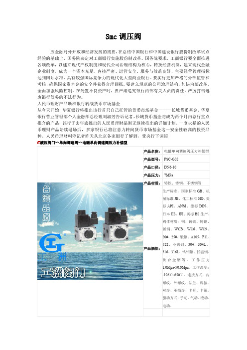
电磁单向调速阀压力补偿型 FS-G02 特点
1、电磁单向调速阀 FS-G02 带压力补偿装置,能维持稳定的流量,不受出入口压力差变化影响,能够精 确地控制执行元件的速度。 2、单向调速阀 FS-G02 使一个方向的流量可以调节,而反向可自由流动,根据标牌刻度可方便调节或重 新设定流量。 3、适合控制机械动作快速、慢速及快速返回之用,非常适于工具机使用。
A2:AC 220V 5: 50HZ A3:AC 380V 6: 60HZ D1:DC 12V 直流省略
D2:DC 24V
电磁单向调速阀压力补偿型 FS-G03 规格表
型号
FS-G02 FSC-G02 FS-G03 FSC-G03
最高使用压力 MPa
7
流量调整范围 ℓ/min
2: 0.05∼2 4: 0.05∼4
Smc 调压阀
应金融对外开放和经济发展的需要,在总结中国银行和中国建设银行股份制改革试点 经验的基础上,国务院决定对工商银行实施股份制改革。国务院要求,工商银行要全面推进 各项改革,以建立现代产权制度和现代公司治理结构为核心,转换经营机制,建立现代金融 企业制度,成为一个资本充足、内控严密、运营安全、服务与效益良好、主要经营管理指标 达到国际水准、具有较强国际竞争力的现代化大型商业银行。要实行更加严格的外部监管和 考核,确保国家资本金的安全并获得合理回报。要建立规范的公司治理结构,加快内部改革, 全面加强风险控制。在处置不良资产时,要严肃追究银行内部有关人员的责任,严厉打击逃 废银行债务的不法行为。 人民币理财产品断档银行转战货币市场基金 从今天开始,华夏银行将推出该行首只自己托管的货币市场基金———长城货币基金。华夏 银行营业管理部个人金融部总经理刘淑芳告诉记者,长城货币基金将成为两个月内总行重点 推介的产品,该行于去年底推出的人民币理财品则无继续推出的详细计划。一度火暴的人民 币理财产品陆续退场后,多家银行已将注意力转向货币市场基金这一安全性较高的投资品 种。人民币理财叫停记者昨天从北京各家银行了解到,受央行下调超
SMC - 减压阀AR系列(带逆流功能)
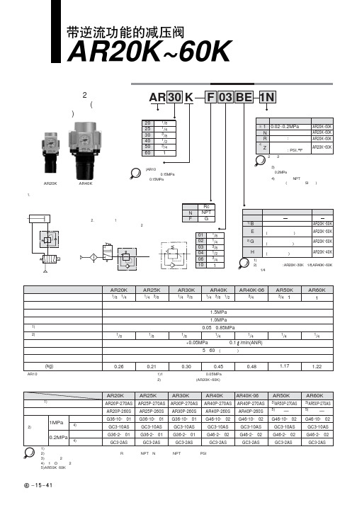
!"#$%& AR20K~60KAR25K AR30K型号表示方法阀·带逆流机构)注1)含托架及安装螺母。
注2)圆形压力表型号中的□表示连接螺纹的种类。
R为无记号、NPT为N。
连接螺纹NPT及单位表示PSI规格的压力表供给,可向营业员询问。
注3)含托架及2个安装螺钉。
注4)含1个O形圈及2个安装螺钉注5)AR50K、60K用安装螺母请向营业员咨询。
例1.气缸的杆侧和无杆侧压力不同的场合回路图AR20K81/4·3/!"#$%&AR20K~60K使用前必读。
安全上的注意、共同注意事项参见前附1~8①在确认一次侧压力表及二次侧压力表的指示压力的同时进行压力设定。
若手轮回转过分,会造成内部零部件的损坏。
②调整手轮应用手调整,不得用工具调整,以免造成损坏。
①手轮开锁后进行压力调整,调整后再锁住。
否则,手轮会损坏或二次侧压力变动。
●调整手轮外拉则开锁(调整手轮下侧看到桔黄色标记可确认)。
●将调整手轮压入则锁住,若难锁时,向左右稍稍回转一下再推压便可。
(锁住时,看不见桔黄色标记。
)②为了防止意外的手轮操作,可提供手轮套。
详见特长1。
③阀芯导座侧(手轮对侧)应留出60mm 的维修空间。
①电磁阀和执行元件等之间设置使用场合的压力表要定期检查。
一旦有剧烈的压力变化,耐久性会变短。
可考虑改用电子式压力表。
1次侧压力(P1)比设定压力高的场合,单向阀②封闭,作为通常的减压阀动作(参见图1)。
一旦1次侧压力排空,单向阀②开启,膜片室①内的压力便从1次侧排出(参见图2)。
这之后,膜片室①内的压力下降,在调压弹簧③的作用下,膜片上推,通过阀杆,将阀芯④打开,2次侧压力便顺利地从1次侧排出(参见图3)。
(1AR20K~60K流量特性(代表值)条件:一次侧压力0.7MPa31!"#$%&AR20K~60KAR20K~60K !AR20K~60K!"#$%&AR20K~60K 外形尺寸图注)仅AR20K的压力表位置在配管中心线上侧。
SMC带逆流功能的减压阀说明书

文件No.:AR ※-OMF0022-B○ 使用产品之前请务必阅读此使用说明书。
○ 请仔细阅读安全注意事项。
○ 为了今后方便使用,请妥善保管使用说明书。
AR25K-(F,N)02~(F,N)03(B,E,G,H)(-1,N,R,Y,Z)产品名称:带逆流功能的减压阀代表型号:AR20K-(F,N)01~(F,N)02(B,E,G,H)(-1,N,R,Y,Z)AR40K-(F,N)02~(F,N)04(B,E,G,H)(-1,N,R,Y,Z)AR40K-(F,N)06(B,E,G,H)(-1,N,R,Y,Z)使 用 说 明 书AR50K-(F,N)06~(F,N)10(B,E,G)(-1,N,R,Y,Z)AR30K-(F,N)02~(F,N)03(B,E,G,H)(-1,N,R,Y,Z)AR60K-(F,N)10(B,E,G)(-1,N,R,Y,Z)目录页1、安全注意事项 1—32、用途43、规格44、型号表示方法45、故障及对策56、构造图/零件清单67、更换操作要领 7—98、分解图 10—119、外观尺寸12SMC(中国)有限公司地址:北京市经济技术开发区兴盛街甲2号 (100176)网址:2、用途 本产品用于气路中的压力控制。
内部设有逆流功能,当入口压力与出口压力相比,下降到规定量时,出口压力将向入口侧开放。
3、型号AR20K AR25K AR30K AR40K AR40K-06AR50KAR60K 管连接口径1/8、1/41/4、3/81/4、3/81/4、3/8、1/23/43/4、11使用流体保证耐压力最高使用压力注1)设定压力范围注2)压力表连接口径环境温度及使用流体温度构造质量0.26kg 0.21kg 0.29kg 0.44kg0.47kg 1.17kg 1.22kg注1) 使1次侧压力比设定压力高0.05MPa以上。
注2) 带四方形埋入式压力计时,没有压力计连接用螺钉。
4、型号表示方法型式空气1.5MPa 1.0MPa -5~60℃(无冻结)溢流型0.05~0.85MPa1/81/4设定压力+0.05MPa{只在溢流流量为0.1L/min (ANR) 时}溢流压力5.故障与对策区分现象压力不能调整1.流向错误。
SMC液压缓冲器

F 2.7 2.7
基本型尺寸 a L H 1.4 43.8 6 1.4 43.8 7
※带胶垫
LL 57.5 58.5
MM M10×1.0 M10×1.0
六角螺母尺寸
Z 10 10
S 51.5 51.5
E3 8.7 8.7
LL 67.5 68.5
B 14 14
C 16.2 16.2
h 4 4
注) RBL(C)1007•1006的尺寸L、LL、S与RB(C)1007•1006不同。
-10~80(未冻结) 水不溶性切削油 4.22 6.18 4.22 6.86 8.73 14.12 8.73 14.61 11.57 17.65 22.16 38.05
※表示每个周期都是在最大吸收能条件下。若使用频度增大,则吸收能量减小。
!"#
RB L
耐冷却液型
C
形式
14
12
可选项 无 带限位螺母 S 追加六角螺母1个(※计3个) J ※安装用六角螺母2个是标准件。 无记号
D 5 5 6 8
E1 12.2 12.2 18.2 25.2
E2 12 12 18 25
F 3.5 3.5 4 5
基本型尺寸 K H LL L 12 11 63.6 83.1 12 12 63.6 84.1 18 15 62.2 88.2 25 25 91.5 129.5
MM M14×1.5 M14×1.5 M20×1.5 M27×1.5
D 5 5 6 8
E1 12.2 12.2 18.2 25.2
E2 12 12 18 25
F 3.5 3.5 4 5
基本型尺寸 K L H 12 58.8 11 12 58.8 12 18 62.2 15 25 86 25
SMC 电子控制气体阀门用户手册说明书
Minimum operating pressure
Single Double (double solenoid) 3 position 4 position
Ambient and fluid temperature
0.1 MPa
0.15 MPa
0.1 MPa
0.1 MPa
0.1 MPa
0.2 MPa
Danger
Danger indicates a hazard with a high level of risk which, if not avoided, will result in death or serious injury.
Warning
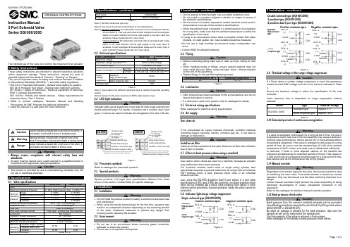
• Always ensure compliance with relevant safety laws and standards.
SMC公司产品说明书
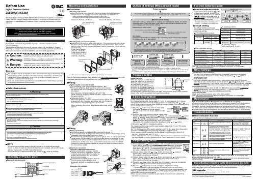
Other SettingsSummary of Product partsSimple Setting ModeTroubleshootingNote: Specifications are subject to change without prior notice and any obligation on the part of the manufacturer.© 2017 SMC Corporation All Rights ReservedAkihabara UDX 15F, 4-14-1, Sotokanda, Chiyoda-ku, Tokyo 101-0021, JAPANPhone: +81 3-5207-8249 Fax: +81 3-5298-5362URL Specifications/Outline with Dimensions (in mm)Refer to the product catalog or SMC website (URL ) for moreinformation about the product specifications and outline dimensions.PS※※-OMU0001 InstallationMounting with bracketMount the bracket to the body with mounting screws (Self tapping screws:Nominal size 3 x 8L (2 pcs)), then set the body to the specified position.∗: Tighten the bracket mounting screws to a torque of 0.5±0.05 Nm.Self tapping screws are used, and should not be re-used several times.∗: The panel mount adapter can be rotated through 90 degrees for mounting.•Bracket A (Part No.: ZS-46-A1)•Bracket B (Part No.: ZS-46-A2)Mounting with panel mount adapterMount part (a) to the front of the body and fix it. Then insert the body with (a) intothe panel until (a) comes into contact with the panel front surface. Next, mountpart (b) to the body from the rear and insert it until (b) comes into contact with thepanel for fixing.WiringWiring connectionsConnections should be made with the power supply turned off.Use a separate route for the product wiring and any power or high voltage wiring.Otherwise, malfunction may result due to noise.If a commercially available switching power supply is used, be sure to ground theframe ground (FG) terminal. If the switching power supply is connected for use,switching noise will be superimposed and it will not be able to meet the productspecifications. In that case, insert a noise filter such as a line noise filter/ferritebetween the switching power supplies or change the switching power supply tothe series power supply.How to use connectorConnector attachment/detachmentWhen connecting the connector, insert itstraight onto the pins, holding the lever andconnector body, and lock the connector bypushing the lever hook into the concavegroove on the housing.To detach the connector, remove the hookfrom the groove by pressing the leverdownward, and pull the connector straightout.DC(+)Pin No.OUT1OUT2FUNCDC(-)BrownBlackWhiteGrayBluePipingTightening the connection threadFor connecting to the body (piping specification: -M5)After hand tightening, apply a spanner of the correct size tothe spanner flats of the piping body, and tighten with a 1/6 to1/4 rotation.As a reference, the tightening torque is 1 to 1.5 Nm.(When replacing the piping adapter ZS-46-N∗, tighten it usingthe same method.)Piping specification: -01, -N01After hand tightening, hold the hexagonal spanner flats of thepressure port with a spanner, and tighten with 2 to 3 rotations.As a reference, the tightening torque is 3 to 5 Nm.When tightening, do not hold the pressure switch body with aspanner.Default settingsWhen the pressure exceeds the setvalue, the switch will be turned on.When the pressure falls below theset value by the amount ofhysteresis or more, the switch willbe turned off. The default setting isto turn on the pressure switch whenthe pressure reaches the centre ofthe atmospheric pressure and upper limit of the rated pressure range. If this condition,shown to the right, is acceptable, then keep these settings.Error indication functionThis function is to display error location and content when a problem or error has occurred.above are displayed, please contact SMC.Refer to the SMC website (URL ) for more information abouttroubleshooting.Power is supplied.button between1 and 3 sec.∗:The outputs will continue to operate during setting.∗:If a button operation is not performed for 3 seconds during the setting, the display will flash.(This is to prevent the setting from remaining incomplete if, for instance, an operator were to leave duringsetting.)∗:3 step setting mode, simple setting mode and function selection mode settings are reflected each other.[3 step setting mode (hysteresis mode)]orcan be changed in the same way.button once when the item to beThe set value on the sub display (right) will startflashing.orbutton.buttons are pressed and held simultaneously for 1 second orlonger, the set value is displayed as [- - -], and the set value will be the same as thecurrent pressure value automatically (snap shot function).Afterwards, it is possible to adjust the value by pressing button.button to complete the setting.The pressure switch turns on within a set pressure range (from P1L to P1H) duringwindow comparator mode.Set P1L, the lower limit of the switch operation, and P1H, the upper limit of the switchoperation and WH1 (hysteresis) following the instructions given above.(When reversed output is selected, the sub display (left) shows [n1L] and [n1H].)∗:Set OUT2 in the same way. (ex. P_2, H_2)∗:Setting of the normal/reverse output switching and hysteresis/window comparator mode switchingare performed with the function selection mode [F 1] OUT1 setting and [F 2] OUT2 setting.value[F 0] Units selection functionPeak/bottom value indicationbutton inmeasurement mode.Snap shot functionbuttons for 1 secondor longer simultaneously. Then, the set value of the sub display (right) shows [- - -], andthe values corresponding to the current pressure values are automatically displayed.Zero-clear functionbuttons are pressed for 1 second orlonger simultaneously, the main display shows [- - -], and the reset to zero.The display returns to measurement mode automatically.Key-lock functionTo set each of these functions, refer to the SMC website(URL ) for more detailed information, or contact SMC.button between 1 and 3 seconds in measurementmode. [SEt] is displayed on the main display. When the button is releasedwhile in the [SEt] display, the current pressure value is displayed on themain display, [P_1] or [n_1] is displayed on the sub display (left), and theset value is displayed on the sub display (right) (Flashing).or button to(The snap shot function can be used.)or button to set the(The snap shot function can be used.)or button, the delay time of the switch output can be selected.button for 2 seconds or longer to complete the setting.∗:If the button is pressed for less than 2 seconds, the setting will moves to the OUT2 setting.In the window comparator mode, set P1L, the lower limit of the switch operation, andP1H, the upper limit of the switch operation, WH1 (hysteresis) and dt1 (delay time)following the instructions given above.(When reversed output is selected, the sub display (left) shows [n1L] and [n1H].)∗:Set OUT2 in the same way.Function selection modebuttonbetween 3 and 5 seconds, to display [F 0].Select to display the function to be changed[F button for 2seconds or longer in function selection modeto return to measurement mode.∗:Some products do not have all the functions. If no functionis available or selected due to configuration of otherfunctions, [- - -] is displayed on the sub display (right).Names of individual partsRefer to the product catalog or SMC website (URL ) for moreinformation about panel cut-out and mounting hole dimensions.Pressure Setting3 Step Setting Mode(URL ) for more detailed information, or contact SMC.MaintenanceHow to reset the product after a power cut or forcible de-energizingThe setting of the product will be retained as it was before a power cut or de-energizing.The output condition is also basically recovered to that before a power cut or de-energizing, but may change depending on the operating environment. Therefore, checkthe safety of the whole installation before operating the product. If the installation is usingaccurate control, wait until the product has warmed up (approximately 10 to 15 minutes). Safety InstructionsBefore UseDigital Pressure SwitchZSE20A(F)/ISE20AThank you for purchasing an SMC ZSE20A(F)/ISE20A Series Digital Pressure Switch.Please read this manual carefully before operating the product and make sure youunderstand its capabilities and limitations. Please keep this manual handy for futurereference.Safety InstructionsThese safety instructions are intended to prevent hazardous situations and/orequipment damage.These instructions indicate the level of potential hazard with the labels of "Caution","Warning" or "Danger". They are all important notes for safety and must be followed inaddition to International standards (ISO/IEC) and other safety regulations.OperatorSwitch ONAt normal output Switch OFFSet valueP_1HysteresisH_1TimePressureDefault settingThe default setting is as follows.If no problem is caused by this setting,keep these settings.Connector pin numbers[F 2] Setting of OUT2Same setting as [F 1] OUT1.NOTE•The direct current power supply to be used should be UL approved as follows:Circuit (of Class 2) which is of maximum 30 Vrms (42.4 V peak), with UL1310 Class2 power supply unit or UL1585 Class 2 transformer.•The product is a UL approved product only if it has a mark on the body.。
SMC电动执行器全系列说明+应用

E-MY更新品
Φ 32, 50
LEM Series
Φ 25, 32
微型出杆式、滑台式
LEP Series
出杆式 Φ 6, 10
带导杆式滑台
高刚性
Φ 25
滚珠丝杠/同步带
Φ 40, 63
LEL Series
LEJ Series
1.无杆式 LEFS、LEFB
安装便捷、结构紧凑
本体、滑台均设有安装孔 高、宽度减少50%
步进电机 (DC24V)
LEFS25 LEFS32
滚珠 丝杠
LEFS40 200~1000 直流伺服 (DC 24V) LEFS16 LEFS25 100~400 100~600
LEFS25S 100~600 交流伺服 (100W/200W LEFS32S 100~800 /400W) LEFS40S 200~1000
行业/设备 CP/汽车尾灯螺钉热压机 应用产品 LEF系列无杆式电缸
序号 1 2
型号 LEFS25B-500-R16N1 LEFS16AA-400-R16N1
数量 1 1
应用说明:两条LEF配合,找到螺钉上料位置,然后加热,再放至螺钉安装位 置进行热压工作,总计4个螺钉8个工位。
行业/设备 电子/标记印刷机 应用产品 LEFS系列无杆式电缸
最大负载 水平[kg] 垂直[kg] 1 5 14 1 2
5 15 25 -
最大速度 [mm/s] 48~1100 48~1400 48~1500 48~2000 Max.2000 Max.2000 Max.2000
定位精度 [mm]
±0.1
±0.08
行业/设备 EP/电表检测机 应用产品 LEF系列无杆式电缸
SMC 气管 TRB
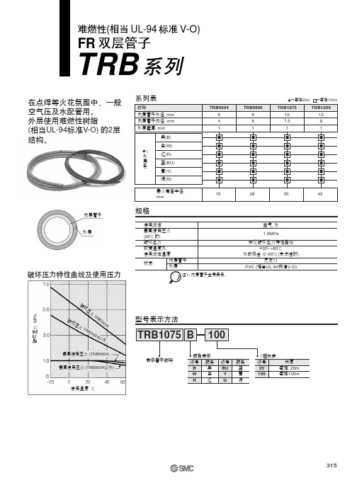
1
1
28
35
45
空气、水
1.0MPa
参见破坏压力特性曲线 -20~+60℃
水的场合:0~60℃(未冻结时) 尼龙11
PVC (相当UL-94标准V-O)
破坏压力 MPa
破坏压力
破坏压力
TRB0604 TRB0604以外
最高使用压力 (TRB0604) 最高使用压力 (TRB0604以外)
使用温度 ℃
外
红(R)
层
蓝(BU)
色
黄(Y)
绿(G)
最小弯曲半径 mm
TRB0604 6 4 1
15
规格
使用流体
最高使用压力 (20℃时)
破坏压力
环境温度及 使用流体温度
材质
内层管子 外层
注1) 内层管子全是黑色。
TRB0806 8 6 1
-每捆20m -每捆100m
TRB1075
TRB1209
10
12
7.5
9
②最高使用压力是20℃时的值。其他温度的场合,参见破坏压力特性曲线。 另外,由于绝热压缩,温度异常升高的场合,会造成管子破裂。
③最小弯曲半径表示温度20℃时,外径变化率在10%以下时的值。温度高于20℃,在最小弯曲半径 以上,外径变化率变成10全部以相同间隔作为安装长度
步骤②
内、外层都切断
仅外层剥离
产品单独注意事项
使用前必读。 安全上的注意、登载产品/共同注意事项见前附1、2。各系列共同注意事 项见P.10、11。
注意
①一般工业用水可使用。除此之外使用的场合,应与本公司联系。 另外,冲击压力应抑制在最高使用压力以下使用。若冲击压力超过最高使用压力,会导致接头破 损,管子破裂。
SMC LEY 16 30 B 1 1 6N 控制器 驱动器和活动器组合说明说明书
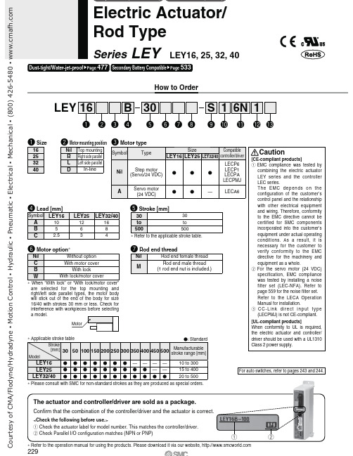
Confirm that the combination of the controller/driver and the actuator is correct.The actuator and controller/driver are sold as a package.<Check the following before use.>: Check the actuator label for model number. This matches the controller/driver.@Check Parallel I/O configuration matches (NPN or PNP)How to OrderLEY Refer to the applicable stroke table.When “With lock” or “With lock/motor cover” are selected for the top mounting and right/left side parallel types, the motor body will stick out of the end of the body for size 16/40 with strokes 30 mm or less. Check for interference with workpieces before selecting a model.Refer to the operation manual for using the products. Please download it via our website, For auto switches, refer to pages 243 and 244.Please consult with SMC for non-standard strokes as they are produced as special orders.:@Electric Actuator/Rod TypeSeries LEY LEY16, 25, 32, 40477533229C o u r t e s y o f C M A /F l o d y n e /H y d r a d y n e ŀ M o t i o n C o n t r o l ŀ H y d r a u l i c ŀ P n e u m a t i c ŀ E l e c t r i c a l ŀ M e c h a n i c a l ŀ (800) 426-5480 ŀ w w w .c m a f h .c o mProduced upon receipt of order (Robotic cable only)Refer to the specifications Note 5) on page 231.1 Mounting bracket is shipped together, (but not assembled).2 For horizontal cantilever mounting with the rod flange, head flange and ends tapped, use the actuator within the following stroke range."LEY25: 200 mm or less "LEY32/40: 100 mm or less3 For mounting with the double clevis, use the actuator within the following stroke range."LEY16: 100 mm or less "LEY25: 200 mm or less "LEY32/40: 200 mm or less4 Rod flange is not available for the LEY16/40 with stroke 30 mm and motor option “With lock”, “With lock/motor cover”.5 H ead flange is not available for the LEY32/40.1 For details about controller/driver and compatible motor, refer to the compatible controller/driver below.2 Only available for the motor type “Step motor.”3 Not applicable to CE.4 When pulse signals are open collector, order the current limiting resistor (LEC-PA-R-;) on page 587 separately.1111 1 DIN rail is not included. Order it separately.Motor mounting position: Top/Parallel 1 T he standard cable should be used on fixedparts. For using on moving parts, select the robotic cable. 2 O nly available for the motor type “Step motor.” 3 F ix the motor cable protruding from the actuator to keep it unmovable. For details about fixing method, refer to Wiring/Cables in the Electric Actuators Precautions.1 When “Without controller/driver” is selected for controller/driver types, I/O cable cannot be selected. Refer to page 559 (For LECP6/ LECA6), page 573 (For LECP1) or page 587 (For LECPA) if I/O cable is required.2 When “Pulse input type” is selected for controller/driver types, pulse input usable only with differential. Only 1.5 m cablesusable with open collector.3 For the LECPMJ, only “Nil”, “S ” and “T” are selectable since I/O cable is not included.Motor mounting position: In-lineCC-Link direct inputLECP6LECA6LECPMJLECP1LECPAValue (Step data) input Standard controllerCC-Link direct inputCapable of setting up Operation by pulse signalsC o u r t e s y o f C M A /F l o d y n e /H y d r a d y n e ŀ M o t i o n C o n t r o l ŀ H y d r a u l i c ŀ P n e u m a t i c ŀ E l e c t r i c a l ŀ M e c h a n i c a l ŀ (800) 426-5480 ŀ w wNote 1) Please consult with SMC for non-standard strokes as they are produced as special orders.Note 2) Horizontal: The maximum value of the work load. An external guide is necessary to support the load (Friction coefficient of guide: 0.1 or less). Theactual work load and transfer speed change according to the condition of the external guide. Also, speed changes according to the work load. Check “Model Selection” on pages 215 and 216.Vertical: Speed changes according to the work load. Check “Model Selection” on pages 215 and 216.The values shown in ( ) are the acceleration/deceleration.Set these values to be 3000 [mm/s 2] or less.Note 3) Pushing force accuracy is o 20% (F.S.).Note 4) The pushing force values for LEY16; is 35% to 85%, for LEY25; is 35% to 65%, for LEY32; is 35% to 85% and for LEY40; is 35% to 65%.The pushing force values change according to the duty ratio and pushing speed. Check “Model Selection” on page 218.Note 5) The speed and force may change depending on the cable length, load and mounting conditions. Furthermore, if the cable length exceeds 5 m, thenit will decrease by up to 10% for each 5 m. (At 15 m: Reduced by up to 20%)Note 6) The allowable speed for pushing operation. When push conveying a workpiece, operate at the vertical work load or less.Note 7) A reference value for correcting an error in reciprocal operation.Note 8) Impact resistance: No malfunction occurred when the actuator was tested with a drop tester in both an axial direction and a perpendicular directionto the lead screw. (Test was performed with the actuator in the initial state.)Vibration resistance: No malfunction occurred in a test ranging between 45 to 2000 Hz. Test was performed in both an axial direction and a perpendicular direction to the lead screw. (Test was performed with the actuator in the initial state.)Note 9) The power consumption (including the controller) is for when the actuator is operating.Note 10) The standby power consumption when operating (including the controller) is for when the actuator is stopped in the set position during theoperation. Except during the pushing operation.Note 11) The maximum instantaneous power consumption (including the controller) is for when the actuator is operating. This value can be used for theselection of the power supply.Note 12) With lock onlyNote 13) For an actuator with lock, add the power consumption for the lock.231C o u r t e s y o f C M A /F l o d y n e /H y d r a d y n e ŀ M o t i o n C o n t r o l ŀ H y d r a u l i c ŀ P n e u m a t i c ŀ E l e c t r i c a l ŀ M e c h a n i c a l ŀ (800) 426-5480 ŀ w wNote 1) Please consult with SMC for non-standard strokes as they areproduced as special orders.Note 2) Horizontal: The maximum value of the work load. An externalguide is necessary to support the load (Friction coefficient of guide: 0.1 or less). The actual work load and transfer speed change according to the condition of the external guide.Vertical: Check “Model Selection” on page 217 for details. The values shown in ( ) are the acceleration/deceleration.Set these values to be 3000 [mm/s 2] or less.Note 3) Pushing force accuracy is o 20% (F.S.).Note 4) The pushing force values for LEY16A ; is 50% to 95% and forLEY25A ; is 50% to 95%. The pushing force values change according to the duty ratio and pushing speed. Check “Model Selection” on page 218.Note 5) The allowable speed for pushing operation. When pushconveying a workpiece, operate at the vertical work load or less.Note 6) A reference value for correcting an error in reciprocal operation.Note 7) Impact resistance: No malfunction occurred when the actuatorwas tested with a drop tester in both an axial direction and a perpendicular direction to the lead screw. (Test was performed with the actuator in the initial state.)Vibration resistance: No malfunction occurred in a test ranging between 45 to 2000 Hz. Test was performed in both an axial direction and a perpendicular direction to the lead screw. (Test was performed with the actuator in the initial state.)Note 8) The power consumption (including the controller) is for whenthe actuator is operating.Note 9) The standby power consumption when operating (including thecontroller) is for when the actuator is stopped in the set position during the operation. Except during the pushing operation.Note 10) The maximum instantaneous power consumption (includingthe controller) is for when the actuator is operating. This value can be used for the selection of the power supply.Note 11) With lock onlyNote 12) For an actuator with lock, add the power consumption for thelock.Weight232C o u r t e s y o f C M A /F l o d y n e /H y d r a d y n e ŀ M o t i o n C o n t r o l ŀ H y d r a u l i c ŀ P n e u m a t i c ŀ E l e c t r i c a l ŀ M e c h a n i c a l ŀ (800) 426-5480 ŀ w wMotor top mounting type: LEY Motor top/parallel type With lock/motor cover16253240233C o u r t e s y o f C M A /F l o d y n e /H y d r a d y n e ŀ M o t i o n C o n t r o l ŀ H y d r a u l i c ŀ P n e u m a t i c ŀ E l e c t r i c a l ŀ M e c h a n i c a l ŀ (800) 426-5480 ŀ w wIn-line motor type: LEY D In-line motor type: With lock/motor cover16253240Grease should be applied at 1 million cycles or 200 km, whichever comes first.234C o u r t e s y o f C M A /F l o d y n e /H y d r a d y n e ŀ M o t i o n C o n t r o l ŀ H y d r a u l i c ŀ P n e u m a t i c ŀ E l e c t r i c a l ŀ M e c h a n i c a l ŀ (800) 426-5480 ŀ w wNote 1) Range within which the rod can move when it returns to origin. Make sure a workpiece mounted on the rod doesnot interfere with the workpieces and facilities around the rod.Note 2) Position after return to origin.Note 3) [ ] for when the direction of return to origin has changed.Note 4) The direction of rod end width across flats (;K) differs depending on the products.Section XX detailsCourtesyofCMA/Flodyne/HydradyneŀMotionControlŀHydraulicŀPneumaticŀElectricalŀMechanicalŀ(8)426-548ŀwwMotor left side parallel type: LEY L16253240Motor right side parallel type: LEY R162532 Note) When the motor is mounted on the left or right side in parallel, the groove for auto switch on the side to which the motor is mounted is hidden.236 CourtesyofCMA/Flodyne/HydradyneŀMotionControlŀHydraulicŀPneumaticŀElectricalŀMechanicalŀ(8)426-548ŀwwNote 1) Range within which the rod can move when it returns to origin. Make sure a workpiece mounted onthe rod does not interfere with the workpieces and facilities around the rod.Note 2) Position after return to origin.Note 3) [ ] for when the direction of return to origin has changed.Note 4) The direction of rod end width across flats (;K) differs depending on the products.Section XX detailsCourtesyofCMA/Flodyne/HydradyneŀMotionControlŀHydraulicŀPneumaticŀElectricalŀMechanicalŀ(8)426-548ŀwwWith motor cover: LEY ;;-;C162532ABCWith lock: LEY;;-;B16253240ABC Motor top/parallel typeCourtesyofCMA/Flodyne/HydradyneŀMotionControlŀHydraulicŀPneumaticŀElectricalŀMechanicalŀ(8)426-548ŀwwWith lock/motor cover: LEY :: -:W 16253240A B CMotor top/parallel type With lock/motor cover: LEY D : -:W 16253240A B C In-line motor typeMaterial: Carbon steel (Chromate treated)The A measurement is when the unit is in the original position. At this position, 2 mm at the end.Note) When the motor mounting is the right or left side paralleltype, the head side foot should be mounted outwards.Included parts" Foot" Body mounting bolt239C o u r t e s y o f C M A /F l o d y n e /H y d r a d y n e ŀ M o t i o n C o n t r o l ŀ H y d r a u l i c ŀ P n e u m a t i c ŀ E l e c t r i c a l ŀ M e c h a n i c a l ŀ (800) 426-5480 ŀ w wC o u r t e s y o f C M A /F l o d y n e /H y d r a d y n e ŀ M o t i o n C o n t r o l ŀ H y d r a u l i c ŀ P n e u m a t i c ŀ E l e c t r i c a l ŀ M e c h a n i c a l ŀ (800) 426-5480 ŀ w wøøøND hole H10axis d9øND hole H10axis d9 Accessory Brackets/Support BracketsI-G02I-G04Y-G02Y-G04 If a knuckle joint is used, select the body option [end male thread].When ordering foot brackets, order 2 pieces per actuator.Parts belonging to each bracket are as follows.Foot: Body mounting boltFlange: Body mounting boltDouble clevis: Clevis pin, Type C retaining ring for axis, Body mounting boltMaterial: Carbon steelMaterial: Carbon steel (Nickel plating)Material: Carbon steelSurface treatment: Nickel platingMaterial: Cast ironSurface treatment: Nickel plating Material: Carbon steelSurface treatment: Nickel platingMaterial: Cast ironSurface treatment: Nickel plating241CourtesyofCMA/Flodyne/HydradyneŀMotionControlŀHydraulicŀPneumaticŀElectricalŀMechanicalŀ(8)426-548ŀwwFloating Joints (Refer to the WEB catalog or the Best Pneumatics No. 2 for details.)Material: Stainless steel<How to Order>u The joint is not included in type A andtype B mounting brackets. Therefore, itmust be ordered separately.no.u Joint.......................................LEY-U025u Type A mounting bracket ......YA-03#For Male Thread/JA#For Male Thread/JS (Stainless steel)"Stainless steel 304(Appearance)"Dust coverFluororubber/Silicone rubber#For Male Thread/JC(Light weight type)"With the aluminum case#For Female Thread/JBBasicFootFlangeCourtesyofCMA/Flodyne/HydradyneŀMotionControlŀHydraulicŀPneumaticŀElectricalŀMechanicalŀ(8)426-548ŀwwAuto Switch SpecificationsWeightDimensionsFix the auto switch with the existing screwinstalled on the auto switch body. The autoswitch may be damaged if a screw otherthan the one supplied is used.[g]Note 1) Refer to the Best Pneumatics No. 2 for solid state auto switch common specifications.Note 2) Refer to the Best Pneumatics No. 2 for lead wire lengths.D-M9;D-M9;V#2-wire load current is reduced(2.5 to 40 mA).# Flexibility is 1.5 times greaterthan the former model (SMCcomparison).#Using flexible cable as standard.[mm]about products conforming to theinternational standards.243CourtesyofCMA/Flodyne/HydradyneŀMotionControlŀHydraulicŀPneumaticŀElectricalŀMechanicalŀ(8)426-548ŀwwAuto Switch SpecificationsWeight[g]Note 1) Refer to the Best Pneumatics No. 2 for solid state auto switch common specifications.Note 2) Refer to the Best Pneumatics No. 2 for lead wire lengths.# 2-wire load current is reduced (2.5 to 40 mA).# Flexibility is 1.5 times greater than the former model (SMC comparison).# Using flexible cable as standard.# The optimum operating range can be determined by the color of the light. (Red l Green j Red)Fix the auto switch with the existing screw installed on the auto switch body. The auto switch may be damaged if a screw other than the one supplied is used.about products conforming to the international standards.C o u r t e s y o f C M A /F l o d y n e /H y d r a d y n e ŀ M o t i o n C o n t r o l ŀ H y d r a u l i c ŀ P n e u m a t i c ŀ E l e c t r i c a l ŀ M e c h a n i c a l ŀ (800) 426-5480 ŀ w w。
A021_HDMI检测机清单部件

設備零件清單設備編號:A021委託加工單號:时间設備名稱:HDMI检测机負責人:杨军2012-5項次零件編號規格/名稱數 量單價合計實際交貨10001鍍硬鉻1 20002_机架 乳白色橘皮烤漆1 301012 401021 501032 601041 701051 801061 901072 100201鍍鉻1 110202鍍硬鉻2 120203鍍硬鉻1 130301HRC58-鍍硬鉻8 140302HRC588 150303鍍硬鉻1 160304HRC582 1703071 180308镀硬铬1 190309镀硬铬1 2003102 210311乳白色橘皮烤漆1 220401镀硬铬1 230402镀硬铬1 240403镀硬铬1 250404镀硬铬1 260405镀硬铬1 270406透明1 280407镀硬铬1 290408镀硬铬1 300409镀硬铬1 310410镀硬铬1 320411透明1 330501镀硬铬1 340502镀硬铬1 350503白色透明2 360508白色透明2 370514HRC55~572 380518镀硬铬1 390519镀硬铬1 400520镀硬铬1 410521镀硬铬1 420522镀硬铬127MSM-LFZB12-6228MSM-MCGSC20_6_35_6_35联轴器229MSM-MPTZ10-25培林组2 30MSM-MSH3-15定位针20 31MSM-MSH5-15定位针30 32MSM-PJLF6-51 33MSM-PLNZS3-100送风喷嘴3 34MSM-SE2B10-155滑轨1 35MSM-SEB10-55滑轨1 36MSM-SLW10垫圈2 37MSM-STWN10卡环4 38OMR-CP1H-X40DT-D PLC1 39OMR-CP1W-CIF01串口1 40OMR-EE-SPX672光电开关2 41OMR-EE-SPX842光电开关142SAN-103H7123-0710(雙軸)马达243SFRW10-44.0-M4-N4844SMC-CDJ2B6-15R-B-2S气缸145SMC-CDU6-10D -2s气缸2 46SMC-CDU6-20D-2s气缸2 47SMC-JA6-3-050浮动接头4 48SMC-RB0604缓冲器149SMC-ZPT06BNJ6-B5-A8吸嘴350SMC-ZX1101-K15LZ-PB真空发生器251TRY-9LA0马达架152TRY-9SBS60P-2N-9S15马达153WN-MT6070iH3人机界面1總計#REF!时间2012-5-30備註。
- 1、下载文档前请自行甄别文档内容的完整性,平台不提供额外的编辑、内容补充、找答案等附加服务。
- 2、"仅部分预览"的文档,不可在线预览部分如存在完整性等问题,可反馈申请退款(可完整预览的文档不适用该条件!)。
- 3、如文档侵犯您的权益,请联系客服反馈,我们会尽快为您处理(人工客服工作时间:9:00-18:30)。
1 产品名称:SMC 缓冲器RB0604
缓冲器在不同的领域有不同的含义:在计算机领域,缓冲器指的是缓冲寄存器,它分输入缓冲器和输出缓冲器两种。
前者的作用是将外设送来的数据暂时存放,以便处理器将它取走;后者的作用是用来暂时存放处理器送往外设的数据。
有了数控缓冲器,就可以使高速工作的CPU 与慢速工作的外设起协调和缓冲作用,实现数据传送的同步。
由于缓冲器接在数据总线上,故必须具有三态输出功能。
在其他领域,还有电梯缓冲器,汽车弹簧缓冲器等,其目的是用于减缓速度,提高安全性和舒适性。
