外文翻译--行星齿轮固有频率-精品
行星齿轮减速器中英文翻译英文资料

附录附录1:英文原文Planetary GearsIntroductionThe Tamiya planetary gearbox is driven by a small DC motor that runs at about 10,500 rpm on 3.0V DC and draws about 1.0A. The maximum speed ratio is 1:400, giving an output speed of about 26 rpm. Four planetary stages are supplied with the gearbox, two 1:4 and two 1:5, and any combination can be selected. Not only is this a good drive for small mechanical applications, it provides an excellent review of epicycle gear trains. The gearbox is a very well-designed plastic kit that can be assembled in about an hour with very few tools. The source for the kit is given in the References.Let's begin by reviewing the fundamentals of gearing, and the trick of analyzing epicyclic gear trains.Epicyclic Gear TrainsA pair of spur gears is represented in the diagram by their pitch circles, which are tangent at the pitch point P. The meshing gear teeth extend beyond the pitch circle by the addendum, and the spaces between them have a depth beneath the pitch circle by the dedendum. If the radii of the pitch circles are a and b, the distance between the gear shafts is a + b. In the action of the gears, the pitch circles roll on one another without slipping. To ensure this, the gear teeth must have a proper shape so that when the driving gear moves uniformly, so does the driven gear. This means that the line of pressure, normal to the tooth profiles in contact, passes through the pitch point. Then, the transmission of power will be free of vibration and high speeds are possible. We won't talk further about gear teeth here, having stated this fundamental principle of gearing.If a gear of pitch radius a has N teeth, then the distance between corresponding points on successive teeth will be 2πa/N, a quantity called the circular pitch. If two gears are to mate, the circular pitches must be the same. The pitch is usually stated as the ration 2a/N, called the diametral pitch. If you count the number of teeth on a gear, then the pitch diameter is the number of teeth times the diametral pitch. If you know the pitch diameters of two gears, then you can specify the distance between the shafts.The velocity ratio r of a pair of gears is the ratio of the angular velocity of the driven gear to the angular velocity of the driving gear. By the condition of rolling of pitch circles, r = -a/b = -N1/N2, since pitch radii are proportional to the number of teeth. The angular velocity n of the gears may be given in radians/sec, revolutions per minute (rpm), or any similar units. If we take one direction of rotation as positive, then the other direction is negative. This is the reason for the (-) sign in the above expression. If one of the gears is internal (having teeth on its inner rim), then the velocity ratio is positive, since the gears will rotate in the same direction.The usual involute gears have a tooth shape that is tolerant of variations in the distance between the axes, so the gears will run smoothly if this distance is not quite correct. The velocity ratio of the gears does not depend on the exact spacing of the axes, but is fixed by the number of teeth, or what is the same thing, by the pitch diameters. Slightly increasing the distance above its theoretical value makes the gears run easier, since the clearances are larger. On the other hand, backlash is also increased, which may not be desired in some applications.An epicyclic gear train has gear shafts mounted on a moving arm or carrier that can rotate about the axis, as well as the gears themselves. The arm can be an input element, or an output element, and can be held fixed or allowed to rotate. The outer gear is the ring gear or annulus. A simple but very common epicyclic train is the sun-and-planet epicyclic train, shown in the figure at the left. Three planetary gears are used for mechanical reasons; they may be considered as one in describing the action of the gearing. The sun gear, the arm, or the ring gear may be input or output links.If the arm is fixed, so that it cannot rotate, we have a simple train of three gears. Then, n2/n1 = -N1/N2, n3/n2 = +N2/N3, and n3/n1 = -N1/N3. This is very simple, and should not be confusing. If the arm is allowed to move, figuring out the velocity ratios taxes the human intellect. Attempting this will show the truth of the statement; if you can manage it, you deserve praise and fame. It is by no means impossible, just invoved. However, there is a very easy way to get the desired result. First, just consider the gear train locked, so it moves as a rigid body, arm and all. All three gears and the arm then have a unity velocity ratio.The trick is that any motion of the gear train can carried out by first holding the arm fixed and rotating the gears relative to one another, and then locking the train and rotating it about the fixed axis. The net motion is the sum or difference of multiples of the two separate motions that satisfies the conditions of the problem (usually that one element is held fixed). To carry out this program, construct a table in which the angular velocities of the gears and arm are listed for each, for each of the two cases. The locked train gives 1, 1, 1, 1 for arm, gear 1, gear 2 and gear 3. Arm fixed gives 0, 1, -N1/N2, -N1/N3. Suppose we want the velocity ration between the arm and gear 1, when gear 3 is fixed. Multiply the first row by a constant so that when it is added to the second row, the velocity of gear 3 will be zero. This constant is N1/N3. Now, doing one displacement and then the other corresponds to adding the two rows. We find N1/N3, 1 + N1/N3, N1/N3 -N1/N2.The first number is the arm velocity, the second the velocity of gear 1, so the velocity ratio between them is N1/(N1 + N3), after multiplying through by N3. This is the velocity ratio we need for the Tamiya gearbox, where the ring gear does not rotate, the sun gear is the input, and the arm is the output. The procedure is general, however, and will work for any epicyclic train.One of the Tamiya planetary gear assemblies has N1 = N2 = 16, N3 = 48, while the other has N1 = 12,N2 = 18, N3 = 48. Because the planetary gears must fit between the sun and ring gears, the condition N3 = N1 + 2N2 must be satisfied. It is indeed satisfied for the numbers of teeth given. The velocity ratio of the first set will be 16/(48 + 16) = 1/4. The velocity ratio of the second set will be 12/(48 + 12) = 1/5. Both ratios are as advertised. Note that the sun gear and arm will rotate in the same direction.The best general method for solving epicyclic gear trains is the tabular method, since it does not contain hidden assumptions like formulas, nor require the work of the vector method. The first step is to isolate the epicyclic train, separating the gear trains for inputs and outputs from it. Find the input speeds or turns, using the input gear trains. There are, in general, two inputs, one of which may be zero in simple problems. Now prepare two rows of the table of turns or angular velocities. The first row corresponds to rotating around the epicyclic axis once, and consists of all 1's. Write down the second row assuming that the arm velocity is zero, using the known gear ratios. The row that you want is a linear combination of these two rows, with unknown multipliers x and y. Summing the entries for the input gears gives two simultaneous linear equations for x and y in terms of the known input velocities. Now the sum of the two rows multiplied by their respective multipliers gives the speeds of all the gears of interest. Finally, find the output speed with the aid of the output gear train. Be careful to get the directions of rotation correct, with respect to a direction taken as positive.The Tamiya Gearbox KitThe parts are best cut from the sprues with a flush-cutter of the type used in electronics. The very small bits of plastic remaining can then be removed with a sharp X-acto knife. Carefully remove all excess plastic, as the instructions say.Read the instructions carefully and make sure that things are the right way up and in the correct relative positons. The gearbox units go together easily with light pressure. Note that the brown ones must go together in the correct relative orientation. The 4mm washers are the ones of which two are supplied, and there is also a full-size drawing of one in the instructions. The smaller washers will not fit over the shaft, anyway. The output shaft is metal. Use larger long-nose pliers to press the E-ring into position in its groove in front of the washer. There is a picture showing how to do this. There was an extra E-ring in my kit. The three prongs fit into the carriers for the planetary gears, and are driven by them.Now stack up the gearbox units as desired. I used all four, being sure to put a 1:5 unit on the end next to the motor. Therefore, I needed the long screws. Press the orange sun gear for the last 1:5 unit firmly on the motor shaft as far as it will go. If it is not well-seated, the motor clip will not close. It might be a good idea to put some lubricant on this gear from the tube included with the kit. If you use a different lubricant, test it first on a piece of plastic from the kit to make sure that it is compatible. A dry graphite lubricant would also work quite well. This should spread lubricant on all parts of the last unit, which is the one subject to the highest speeds. Put the motor in place, gently but firmly, wiggling it so that the sun gear meshes. If the sun gear is not meshed, the motor clip will not close. Now put the motor terminals in a vertical column, and press on the motor clamp.The reverse of the instructions show how to attach the drive arm and gives some hints on use of the gearbox. I got an extra spring pin, and two extra 3 mm washers. If you have some small washers, they can be used on the machine screws holding the gearbox together. Enough torque is produced at the output to damage things (up to 6 kg-cm), so make sure the output arm can rotate freely. I used a standard laboratory DC supply with variable voltage and current limiting, but dry cells could be used as well. The current drain of 1 A is high even for D cells, so a power supply is indicated for serious use. The instructions say not to exceed 4.5V, which is good advice. With 400:1 reduction, the motor should run freely whatever the output load.My gearbox ran well the first time it was tested. I timed the output revolutions with a stopwatch, and found 47s for 20 revolutions, or 25.5 rpm. This corresponds to 10,200 rpm at the motor, which is close tospecifications. It would be easy to connect another gearbox in series with this one (parts are included to make this possible), and get about 4 revolutions per hour. Still another gearbox would produce about one revolution in four days. This is an excellent kit, and I recommend it highly.Other Epicyclic TrainsA very famous epicyclic chain is the Watt sun-and-planet gear, patented in 1781 as an alternative to the crank for converting the reciprocating motion of a steam engine into rotary motion. It was invented by William Murdoch. The crank, at that time, had been patented and Watt did not want to pay royalties. An incidental advantage was a 1:2 increase in the rotative speed of the output. However, it was more expensive than a crank, and was seldom used after the crank patent expired. Watch the animation on Wikipedia.The input is the arm, which carries the planet gear wheel mating with the sun gear wheel of equal size. The planet wheel is prevented from rotating by being fastened to the connecting rod. It oscillates a little, but always returns to the same place on every revolution. Using the tabular method explained above, the first line is 1, 1, 1 where the first number refers to the arm, the second to the planet gear, and the third to the sun gear. The second line is 0, -1, 1, where we have rotated the planet one turn anticlockwise. Adding, we get 1, 0, 2, which means that one revolution of the arm (one double stroke of the engine) gives two revolutions of the sun gear.We can use the sun-and-planet gear to illustrate another method for analyzing epicyclical trains in which we use velocities. This method may be more satisfying than the tabular method and show more clearly how the train works. In the diagram at the right, A and O are the centres of the planet and sun gears, respectively. A rotates about O with angular velocity ω1, which we assume clockwise. At the position shown, this gives A a velocity 2ω1 upward, as shown. Now the planet gear does not rotate, so all points in it move with the same velocity as A. This includes the pitch point P, which is also a point in the sun gear, which rotates about the fixed axis O with angular velocity ω2. Therefore, ω2= 2ω1, the same result as with the tabular method.The diagram at the left shows how the velocity method is applied to the planetary gear set treated above. The sun and planet gears are assumed to be the same diameter (2 units). The ring gear is then of diameter 6. Let us assume the sun gear is fixed, so that the pitch point P is also fixed. The velocity of point A is twice the angular velocity of the arm. Since P is fixed, P' must move at twice the velocity of A, or four times the velocity of the arm. However, the velocity of P' is three times the angular velocity of the ring gearas well, so that 3ωr= 4ωa. If the arm is the input, the velocity ratio is then 3:4, while if the ring is the input, the velocity ratio is 4:3.A three-speed bicycle hub may contain two of these epicyclical trains, with the ring gears connected (actually, common to the two trains). The input from the rear sprocket is to the arm of one train, while the output to the hub is from the arm of the second train. It is possible to lock one or both of the sun gears to the axle, or else to lock the sun gear to the arm and free of the axle, so that the train gives a 1:1 ratio. The three gears are: high, 3:4, output train locked; middle, 1:1, both trains locked, and low, 4:3 input train locked. Of course, this is just one possibility, and many different variable hubs have been manufactured. The planetary variable hub was introduced by Sturmey-Archer in 1903. The popular AW hub had the ratios mentioned here.Chain hoists may use epicyclical trains. The ring gear is stationary, part of the main housing. The input is to the sun gear, the output from the planet carrier. The sun and planet gears have very different diameters, to obtain a large reduction ratio.The Model T Ford (1908-1927) used a reverted epicyclic transmission in which brake bands applied to the shafts carrying sun gears selected the gear ratio. The low gear ratio was 11:4 forward, while the reverse gear ratio was -4:1. The high gear was 1:1. Reverted means that the gears on the planet carrier shaft drove other gears on shafts concentric with the main shaft, where the brake bands were applied. The floor controls were three pedals: low-neutral-high, reverse, transmission brake. The hand brake applied stopped theleft-hand pedal at neutral. The spark advance and throttle were on the steering column.The automotive differential, illustrated at the right, is a bevel-gear epicyclic train. The pinion drives the ring gear (crown wheel) which rotates freely, carrying the idler gears. Only one idler is necessary, but more than one gives better symmetry. The ring gear corresponds to the planet carrier, and the idler gears to the planet gears, of the usual epicyclic chain. The idler gears drive the side gears on the half-axles, which correspond to the sun and ring gears, and are the output gears. When the two half-axles revolve at the same speed, the idlers do not revolve. When the half-axles move at different speeds, the idlers revolve. The differential applies equal torque to the side gears (they are driven at equal distances by the idlers) while allowing them to rotate at different speeds. If one wheel slips, it rotates at double speed while the other wheel does not rotate. The same (small) torque is, nevertheless, applied to both wheels.The tabular method is easily used to analyze the angular velocities. Rotating the chain as a whole gives 1, 0, 1, 1 for ring, idler, left and right side gears. Holding the ring fixed gives 0, 1, 1, -1. If the right side gear isheld fixed and the ring makes one rotation, we simply add to get 1, 1, 2, 0, which says that the left side gear makes two revolutions. The velocity method can also be used, of course. Considering the (equal) forces exerted on the side gears by the idler gears shows that the torques will be equal.ReferencesTamiya Planetary Gearbox Set, Item 72001-1400. Edmund Scientific, Catalog No. C029D, itemD30524-08 ($19.95).C. Carmichael, ed., Kent's Mechanical Engineer's Handbook, 12th ed. (New York: John Wiley and Sons, 1950). Design and Production Volume, p.14-49 to 14-43.V. L. Doughtie, Elements of Mechanism, 6th ed. (New York: John Wiley and Sons, 1947). pp. 299-311.Epicyclic gear. Wikipedia article on epicyclic trains.Sun and planet gear. Includes an animation.英文译文介绍Tamiya行星轮变速箱由一个约 10500 r/min,3.0V,1.0A的直流电机运行。
齿轮基本术语(中英文对照)

齿轮基本术语(中英文对照)齿轮基本术语(中英文对照)齿轮 Toothed gear;Gear齿轮副 Gear pair平行轴齿轮副 Gear pair with parallel axes相交轴齿轮副 Gear pair with intersecting axes 齿轮系 Train of gears行星齿轮系 Planetary gear train齿轮传动 Gear drive;Gear transmission配对齿轮 Mating gears小齿轮 Pinion大齿轮 Wheel;Gear主动齿轮 Driving gear从动齿轮 Driven gear行星齿轮 Planet gear行星架 Planet carrier太阳轮 Sun gear内齿圈 Ring gear;Annulus gear外齿轮 External gear内齿轮 Internal gear中心距 Centre distance轴交角 Shaft angle连心线 Line of centres减速齿轮副 Speed reducing gear pair增速齿轮副 Speed increasing gear pair齿数比 Gear ratio传动比 Transmission ratio轴平面 Axial plane基准平面 Datum plane节平面 Pitch plane端平面 Transverse plane法平面 Normal plane分度曲面 Reference surface节曲面 Pitch surface齿顶曲面 Tip surface齿根曲面 Root surface基本齿廓 Basic toothprofile基本齿条 Basic rack产形齿条 Counterpart rack产形齿轮 Generating gear of a gear产形齿面 Generating flank基准线 Datum line轮齿 Gear teeth;T ooth齿槽 Tooth space右旋齿 Right-hand teeth左旋齿 Left-hand teeth变位齿轮 Gears with addendum modification;X-gears高度变位圆柱齿轮副X-gear pair with reference centre distance角度变位圆柱齿轮副 X-gear pair with modified centre distance 高度变位锥齿轮副X-gear pair without shaft angle modification角度变位圆柱齿轮副 X-gear pair with shaft angle modification 变位系数 Modification coefficient变位量 Addendummodification径向变位系数 Addendum modification coefficient中心距变位系数 Centre distance modification coefficient 圆柱齿轮 Cylindrical gear顶圆 Tip circle根圆 Root circle齿距 Pitch齿距角 Angular pitch公法线长度 Base tangent length分度圆直径 Reference diameter节圆直径 Pitch diameter基圆直径 Base diameter顶圆直径 Tip diameter根圆直径 Root diameter齿根圆角半径 Fillet radius齿高 Tooth depth工作高度 Working depth齿顶高 Addendum齿根高 Dedendum弦齿高 Chordal height固定弦齿高 Constant chord height齿宽 Facewidth有效齿宽 Effectivefacewidth端面齿厚 Transverse tooth thickness法向齿厚 Normal tooth thickness端面基圆齿厚 Transverse base thickness法向基圆齿厚 Normal base thickness端面弦齿厚 Transverse chordal tooth thickness固定弦齿厚 Constant chord端面齿顶厚 Crest width法向齿顶厚 Normal crest width端面齿槽宽 Transverse spacewidth法向齿槽宽 Normal spacewidth齿厚半角 Tooth thickness half angle槽宽半角 Spacewidth half angle压力角 Pressure angle齿形角 Nominal pressure angle圆弧圆柱蜗杆Arc-contact worm;hollow flank worm;ZC-worm直廓环面蜗杆 Enveloping worm with straight line grneratrix;TA worm平面蜗杆 Planar worm wheel;P-worm wheel平面包络环面蜗杆 Planar double enveloping worm;TP-worm 平面二次包络蜗杆Planar double-enveloping worm wheel;TP-worm wheel锥面包络环面蜗杆 T oroid enveloping worm wheel;TK-worm wheel渐开线包络环面蜗杆Toroid enveloping worm hich involute holicoid generatrix;TI-worm锥蜗杆 Spiroid锥蜗轮 Spiroid gear锥蜗杆副 Spiroid gear pair中平面 Mid-plane长幅内摆线 Prolate hypocycloid短幅内摆线 Curtate hypocycloid渐开线 Involute;Involute to a circle延伸渐开线 Prolateinvolute缩短渐开线 Curtateinvolute球面渐开线 Sphericalinvolute渐开螺旋面 Involutehelicoid阿基米德螺旋面 Screwhelicoid球面渐开螺旋面 Spherical involute helicoid 圆环面 T oroid圆环面的母圈 Generant of the toroit圆环面的中性圈 Middle circle of the toroid 圆环面的中间平面 Middle-plane of the toroid圆环面的内圈 Inner circle of the toroid啮合干涉 Meshinginterference切齿干涉 Cutterinterference齿廓修型 Profile modification;Profile correction修缘 Tip relief修根 Root relief齿向修形 Axialmodification;Longitudinal correction齿端修薄 End relief鼓形修整 Crowning鼓形齿 Crowned teeth挖根 Undercut瞬时轴 Instantaneous axis瞬时接触点 Point of contact瞬时接触线 Line of contact端面啮合线 Transverse path of contact啮合曲面 Surface of action啮合平面 Plane of action啮合区域 Zone of action总作用弧 Total arc of transmission端面作用弧 Transverse arc of transmission 纵向作用弧 Overlap arc总作用角 Total angle of transmission端面作用角 Transverse angle of transmission 纵向作用角 Overlap angle总重合度 Total contactratio端面重合度 Transverseratio纵向重合度 Overlap ratio标准齿轮 Standard gears非变位齿轮 X-gero gear标准中心距 Referencr centre distance名义中心距 Nominal centre distance分度圆柱面 Referencecylinder节圆柱面 Pitch cylinder基圆柱面 Basic cylinder齿顶圆柱面 Tip cylinder齿根圆柱面 Root cylinder节点 Pitch point节线 Pitch line分度圆 Reference circle节圆 Pitch circle基圆 Basic circle定位面 Locating face外锥距 Outer cone distance内锥距 Inner cone distance中点锥距 Mean cone distance背锥距 Back cone distance安装距 Locating distance轮冠距 Tip distance;crown to back 冠顶距 Apex to crown偏置距 Offset齿线偏移量 Offset of tooth trace分锥角 Reference cone angle节锥角 Pitch cone angle顶锥角 Tip angle根锥角 Root angle背锥角 Back cone angle齿顶角 Addendum angel齿根角 Dedendum angle任意点压力角 Pressure angle at a point 任意点螺旋角 Spiral angle at a point 中点螺旋角 Mean spiralangle大端螺旋角 Outer spiral angle小端螺旋角 Inner spiral angle蜗杆 Worm蜗轮 Worm wheel蜗杆副 Worm gear pair圆柱蜗杆 Cylindrical worm圆柱蜗杆副 Cylindrical worm pair环面蜗杆 Enveloping worm环面蜗杆副 Enveloping worm pair阿基米德蜗杆 Straight sided axial worm;ZA-worm 渐开线蜗杆 Involute helicoidworm;ZI-worm法向直廓蜗杆 Straight sided normal worm;ZN-worm 锥面包络圆柱蜗杆 Milled helicoid worm;ZK-worm 椭圆齿轮 Elliptical gear非圆齿轮副 Non-circular gear pair圆柱针轮副 Cylindsical lantern pinion and wheel针轮 Cylindsical tan tein gear ;pin-wheel谐波齿轮副 Harmoric gear drive波发生器 Wave generator柔性齿轮 Flexspine刚性齿轮 Circular spline非圆齿轮 Non-circular gear分度圆环面 Reference tosoid。
齿轮术语中英文对照
齿轮术语中英文对照Toothed gear;;齿轮Gear齿轮副Gear pair Gear pair with平行轴齿轮副parallel axes Gear pair with相交轴齿轮副intersecting axes齿轮系Train of gears Planetary gear行星齿轮系train Gear drive;Gear ;齿轮传动transmission配对齿轮Mating gears相啮齿面Mating flank阿基米德螺旋面Screw helicoid Spherical involute小齿轮Pinion共轭齿面Conjugate flank球面渐开螺旋面helicoid大齿轮主动齿轮Wheel;Gear ;Driving gear可用齿面有效齿面Usable flank Active flank圆环面圆环面的母圈Toroid Generant of the toroit Middle circle of the 从动齿轮Driven gear上齿面Addendum flank圆环面的中性圈toroid Middle-plane of the行星齿轮Planet gear下齿面Dedendum flank圆环面的中间平面toroid行星架太阳轮Planet carrier Sun gear Ring gear;;内齿圈Annulus gear Profile modification;;外齿轮External gear齿廓Tooth profile齿廓修型Profile correction内齿轮中心距Internal gear Centre distance端面齿廓法向齿廓Transverse profile Normal profile修缘修根Tip relief Root relief Axial modification;;轴交角Shaft angle轴向齿廓Axial profile齿向修形Longitudinal correction Back cone tooth连心线Line of centres背锥齿廓profile Speed reducing减速齿轮副gear pair Speed increasing增速齿轮副gear pair齿数比Gear ratio Transmission传动比ratio轴平面Axial plane法向模数Normal module瞬时接触点Point of contact端面模数Transverse module瞬时轴Instantaneous axis模数Module挖根Undercut齿棱Tip;Tooth tip ;鼓形齿Crowned teeth齿线Tooth trace鼓形修整Crowning齿端修薄End relief槽底Bottom land切齿干涉Cutter interference齿根过渡曲面齿顶Fillet Crest;Top land ;圆环面的内圈啮合干涉Inner circle of the toroid Meshing interference 非工作齿面Non-working flank渐开螺旋面Involute helicoid工作齿面Working flank球面渐开线Spherical involute异侧齿面Opposite flank缩短渐开线Curtate involute同侧齿面Corresponding flank延伸渐开线Prolate involute左侧齿面Left flank渐开线Involute to a circle右侧齿面Right flank短幅内摆线Curtate hypocycloid Involute;;齿面Tooth flank长幅内摆线Prolate hypocycloid基准平面Datum plane轴向模数Axial module瞬时接触线Line of contact Transverse path of节平面Pitch plane径节Diametral pitch端面啮合线contact端平面Transverse plane齿数Number of teech Virtual number of啮合曲面Surface of action法平面Normal plane当量齿数teeth Number of starts;;啮合平面Plane of action分度曲面Reference surface头数Number of threads啮合区域Zone of action节曲面Pitch surface螺旋线Helix;Circular helix ;总作用弧Total arc of transmission Transverse arc of齿顶曲面Tip surface圆锥螺旋线Conical spiral端面作用弧transmission Helix angle;;齿根曲面Root surface螺旋角Spiral angle Total angle of基本齿廓基本齿廓Basic tooth profile导程Lead总作用角transmission Transverse angle of基本齿条Basic rack导程角Lead angle端面作用角transmission产形齿条Counterpart rack Generating gear产形齿轮of a gear产形齿面基准线轮齿齿槽Generating flank Datum line Gear teeth;Tooth ;Tooth space长幅外摆线短幅外摆线摆线长幅摆线Prolate epoicycloid Curtate epoicycloid Cycloid Prolate cycloid端面重合度纵向重合度标准齿轮非变位齿轮Transverse ratio Overlap ratio Standard gears X-gero gear Referencr centre右旋齿Right-hand teeth短幅摆线Curtate cycloid标准中心距distance左旋齿Left-hand teeth Gears with addendum变位齿轮modification;;X-gears X-gear pair with高度变位圆柱齿轮reference centre副distance X-gear pair with角度变位圆柱齿轮modified centre副distance X-gear pair without shaft高度变位锥齿轮副angle modification角度变位圆柱齿轮X-gear pair with人字齿轮Double-helical gear齿根圆柱面Root cylinder斜齿条Helical rack齿顶圆柱面Tip cylinder直齿条Spur rack基圆柱面Basic cylinder斜齿轮Single-helical gear Helical gear;;节圆柱面Pitch cylinder直齿轮Spur gear分度圆柱面Reference cylinder内摆线Hypocycloid名义中心距Nominal centre distance外摆线Epicycloid总重合度Total contact ratio阿基米德螺旋线Archimedes spiral纵向作用角Overlap angle纵向作用弧Overlap arc副shaft angle modification Modification Involute cylindrical渐开线齿轮coefficient Addendum gear节点Pitch point变位系数变位量modification Addendum摆线齿轮Cycloidal gear节线Pitch line Circular-arc gear;;径向变位系数modification coefficient Centre distance Double-circular-arc中心距变位系数modification coefficient圆柱齿轮Cylindrical gear假想曲面Imaginary surfance Normal pressure顶圆Tip circle任意点法向压力角angle at a point Transverse pressure根圆Root circle任意点端面压力角angle at a point Working pressure齿距Pitch啮合角angle齿距角Angular pitch Base tangent公法线长度length Reference分度圆直径diameter Tip distance;crown to ;节圆直径Pitch diameter径向侧隙Radial blacklash轮冠距back基圆直径顶圆直径根圆直径齿根圆角半径齿高工作高度齿顶高Base diameter Tip diameter Root diameter Fillet radius Tooth depth Working depth Addendum锥齿轮锥齿轮副准双曲面齿轮副准双曲面齿轮冠轮端面齿轮直齿锥齿轮Bevel gear Bevel gear pair Hypoid gear pair Hypoid gear Crown gear Contrate gear Straight bevel gear Skew bevel gear;;齿根高Dedendum斜齿锥齿轮Helical bevel gear Curved tooth bevel弦齿高Chordal height曲面齿锥齿轮gear Constant chord固定弦齿高height Enicycloid bevel齿宽Facewidth摆线齿锥齿轮gear有效齿宽Effective零度齿锥齿轮Zerot bevel gear任意点螺旋角Spiral angle at a point任意点压力角Pressure angle at a point弧齿锥齿轮Spiral bevel gear齿根角Dedendum angle齿顶角Addendum angel背锥角Back cone angle冠顶距偏置距齿线偏移量分锥角节锥角顶锥角根锥角Apex to crown Offset Offset of tooth trace Reference cone angle Pitch cone angle Tip angle Root angle法向侧隙Normal blacklash安装距Locating distance圆周侧隙blacklash顶隙Bottom clearance Circumferential背锥距Back cone distance中点锥距Mean cone distance内锥距Inner cone distance外锥距Outer cone distance定位面Locating face基圆Basic circle双圆弧齿轮gear节圆Pitch circle圆弧齿轮W-N gear分度圆Reference circle facewidth Transverse tooth端面齿厚thickness Normal tooth法向齿厚thickness Transverse base端面基圆齿厚thickness Spiral bevel gear Normal base法向基圆齿厚thickness profile Transverse端面弦齿厚chordal tooth thickness固定弦齿厚端面齿顶厚Constant chord Crest width Normal crest法向齿顶厚width Transverse端面齿槽宽spacewidth Normal法向齿槽宽spacewidth Tooth thickness齿厚半角half angle Spacewidth half槽宽半角angle Crossing point of压力角Pressure angle轴线交点axes Nominal pressure齿形角angle Arc-contact worm;hollow ;圆弧圆柱蜗杆flank worm;;ZC-worm Enveloping worm with straight line直廓环面蜗杆grneratrix;TA ;worm Planar worm Cylindsical lantern平面蜗杆wheel;P-worm ;wheel Planar double平面包络环面蜗杆enveloping worm;;喉圆Gorge circle 针轮gear ;pin-wheel Cylindsical tan tein喉平面Gorge plane圆柱针轮副pinion and wheel咽喉面Gorge非圆齿轮副非圆齿轮副Non-circular gear pair齿根圆环面Root tosoid椭圆齿轮Elliptical gear公共锥顶Common apex锥面包络圆柱蜗杆ZK-worm法向直廓蜗杆worm;ZN-worm ;Milled helicoid worm;;分锥顶点Reference cone apex渐开线蜗杆ZI-worm Straight sided normal中锥面Middle cone阿基米德蜗杆worm;ZA-worm ;Involute helicoid worm;;Straight sided axial 前锥面Front cone环面蜗杆副Enveloping worm pair背锥面Back cone环面蜗杆Enveloping worm齿根圆锥面Root cone圆柱蜗杆副Cylindrical worm pair节圆锥面齿顶圆锥面Pitch cone Face cone;tip cone ;蜗杆副圆柱蜗杆Worm gear pair Cylindrical worm分度圆锥面Reference cone蜗轮Worm wheel圆柱齿弧锥齿轮with circle arc tooth蜗杆Worm 8 字啮合锥齿轮Octoid gear小端螺旋角Inner spiral angle锥齿轮的当量圆柱齿轮gear of bevel gear Virtual cylindrical大端螺旋角Outer spiral angle圆柱齿轮端面齿轮副Contrate gear pair中点螺旋角Mean spiral angle TP-worm Planar double-enveloping平面二次包络蜗杆worm wheel;;TP-worm wheel Toroid enveloping锥面包络环面蜗杆worm wheel;;TK-worm wheel Toroid enveloping worm hich 渐开线包络环面蜗involute holicoid杆generatrix;;TI-worm Worm wheel锥蜗杆Spiroid蜗轮齿宽facewidth锥蜗轮锥蜗杆副中平面Spiroid gear Spiroid gear pair Mid-plane直径系数咽喉半径齿宽角Diametral quotient Gorge radius Width angle非圆齿轮分度圆环面Non-circular gear Reference tosoid刚性齿轮Circular spline蜗杆齿宽Worm facewidth柔性齿轮Flexspine螺纹Thread波发生器Wave generator分度圆蜗旋线Reference helix谐波齿轮副Harmoric gear drive。
机械专业中英文对照大全 机械工程师必备【精选文档】

机械专业英语词汇陶瓷ceramics合成纤维synthetic fibre电化学腐蚀electrochemical corrosion 车架automotive chassis悬架suspension转向器redirector变速器speed changer板料冲压sheet metal parts孔加工spot facing machining车间workshop工程技术人员engineer气动夹紧pneuma lock数学模型mathematical model画法几何descriptive geometry机械制图Mechanical drawing投影projection视图view剖视图profile chart标准件standard component零件图part drawing装配图assembly drawing尺寸标注size marking技术要求technical requirements刚度rigidity内力internal force位移displacement截面section疲劳极限fatigue limit断裂fracture塑性变形plastic distortion脆性材料brittleness material刚度准则rigidity criterion垫圈washer垫片spacer直齿圆柱齿轮straight toothed spur gear 斜齿圆柱齿轮helical-spur gear直齿锥齿轮straight bevel gear运动简图kinematic sketch齿轮齿条pinion and rack蜗杆蜗轮worm and worm gear虚约束passive constraint曲柄crank 摇杆racker凸轮cams共轭曲线conjugate curve范成法generation method定义域definitional domain值域range导数\\微分differential coefficient求导derivation定积分definite integral不定积分indefinite integral曲率curvature偏微分partial differential毛坯rough游标卡尺slide caliper千分尺micrometer calipers攻丝tap二阶行列式second order determinant逆矩阵inverse matrix线性方程组linear equations概率probability随机变量random variable排列组合permutation and combination气体状态方程equation of state of gas动能kinetic energy势能potential energy机械能守恒conservation of mechanical energy动量momentum桁架truss轴线axes余子式cofactor逻辑电路logic circuit触发器flip-flop脉冲波形pulse shape数模digital analogy液压传动机构fluid drive mechanism机械零件mechanical parts淬火冷却quench淬火hardening回火tempering调质hardening and tempering磨粒abrasive grain结合剂bonding agent砂轮grinding wheel后角clearance angle龙门刨削planing主轴spindle主轴箱headstock卡盘chuck加工中心machining center车刀lathe tool车床lathe钻削镗削bore车削turning磨床grinder基准benchmark钳工locksmith锻forge压模stamping焊weld拉床broaching machine拉孔broaching装配assembling铸造found流体动力学fluid dynamics流体力学fluid mechanics加工machining液压hydraulic pressure切线tangent机电一体化mechanotronics mechanical-electrical integration气压air pressure pneumatic pressure稳定性stability介质medium液压驱动泵fluid clutch液压泵hydraulic pump阀门valve失效invalidation强度intensity载荷load应力stress安全系数safty factor可靠性reliability螺纹thread螺旋helix键spline销pin滚动轴承rolling bearing滑动轴承sliding bearing弹簧spring制动器arrester brake十字结联轴节crosshead联轴器coupling链chain皮带strap精加工finish machining粗加工rough machining变速箱体gearbox casing腐蚀rust氧化oxidation磨损wear耐用度durability随机信号random signal离散信号discrete signal超声传感器ultrasonic sensor集成电路integrate circuit挡板orifice plate残余应力residual stress套筒sleeve扭力torsion冷加工cold machining电动机electromotor汽缸cylinder过盈配合interference fit热加工hotwork摄像头CCD camera倒角rounding chamfer优化设计optimal design工业造型设计industrial moulding design有限元finite element滚齿hobbing插齿gear shaping伺服电机actuating motor铣床milling machine钻床drill machine镗床boring machine步进电机stepper motor丝杠screw rod导轨lead rail组件subassembly可编程序逻辑控制器Programmable Logic Controller PLC电火花加工electric spark machining电火花线切割加工electrical discharge wire —cutting相图phase diagram热处理heat treatment固态相变solid state phase changes有色金属nonferrous metal陶瓷ceramics合成纤维synthetic fibre电化学腐蚀electrochemical corrosion车架automotive chassis悬架suspension转向器redirector变速器speed changer板料冲压sheet metal parts孔加工spot facing machining车间workshop工程技术人员engineer气动夹紧pneuma lock数学模型mathematical model画法几何descriptive geometry机械制图Mechanical drawing投影projection视图view剖视图profile chart标准件standard component零件图part drawing装配图assembly drawing尺寸标注size marking技术要求technical requirements刚度rigidity内力internal force位移displacement截面section疲劳极限fatigue limit断裂fracture塑性变形plastic distortion脆性材料brittleness material刚度准则rigidity criterion垫圈washer垫片spacer直齿圆柱齿轮straight toothed spur gear斜齿圆柱齿轮helical-spur gear 直齿锥齿轮straight bevel gear运动简图kinematic sketch齿轮齿条pinion and rack蜗杆蜗轮worm and worm gear虚约束passive constraint曲柄crank摇杆racker凸轮cams共轭曲线conjugate curve范成法generation method定义域definitional domain值域range导数\\微分differential coefficient求导derivation定积分definite integral不定积分indefinite integral曲率curvature偏微分partial differential毛坯rough游标卡尺slide caliper千分尺micrometer calipers攻丝tap二阶行列式second order determinant逆矩阵inverse matrix线性方程组linear equations概率probability随机变量random variable排列组合permutation and combination气体状态方程equation of state of gas动能kinetic energy势能potential energy机械能守恒conservation of mechanical energy 动量momentum桁架truss轴线axes余子式cofactor逻辑电路logic circuit触发器flip-flop脉冲波形pulse shape数模digital analogy液压传动机构fluid drive mechanism机械零件mechanical parts淬火冷却quench淬火hardening回火tempering调质hardening and tempering磨粒abrasive grain结合剂bonding agent砂轮grinding wheelAssembly line 组装线Layout 布置图Conveyer 流水线物料板Rivet table 拉钉机Rivet gun 拉钉枪Screw driver 起子Pneumatic screw driver 气动起子worktable 工作桌OOBA 开箱检查fit together 组装在一起fasten 锁紧(螺丝)fixture 夹具(治具)pallet 栈板barcode 条码barcode scanner 条码扫描器fuse together 熔合fuse machine热熔机repair修理operator作业员QC品管supervisor 课长ME 制造工程师MT 制造生技cosmetic inspect 外观检查inner parts inspect 内部检查thumb screw 大头螺丝lbs. inch 镑、英寸EMI gasket 导电条front plate 前板rear plate 后板chassis 基座bezel panel 面板power button 电源按键reset button 重置键Hi—pot test of SPS 高源高压测试Voltage switch of SPS 电源电压接拉键sheet metal parts 冲件plastic parts 塑胶件SOP 制造作业程序material check list 物料检查表work cell 工作间trolley 台车carton 纸箱sub—line 支线left fork 叉车personnel resource department 人力资源部production department生产部门planning department企划部QC Section品管科stamping factory冲压厂painting factory烤漆厂molding factory成型厂common equipment常用设备uncoiler and straightener整平机punching machine 冲床robot机械手hydraulic machine油压机lathe车床planer |plein|刨床miller铣床grinder磨床linear cutting线切割electrical sparkle电火花welder电焊机staker=reviting machine铆合机position职务president董事长general manager总经理special assistant manager特助factory director厂长department director部长deputy manager | =vice manager副理section supervisor课长deputy section supervisor =vice section superisor副课长group leader/supervisor组长line supervisor线长assistant manager助理to move,to carry,to handle搬运be put in storage入库pack packing包装to apply oil擦油to file burr 锉毛刺final inspection终检to connect material接料to reverse material 翻料wet station沾湿台Tiana天那水cleaning cloth抹布to load material上料to unload material卸料to return material/stock to退料scraped |\\’skr?pid|报废scrape ..v.刮;削deficient purchase来料不良manufacture procedure制程deficient manufacturing procedure制程不良oxidation |\\’ ksi\\'dei?n|氧化scratch刮伤dents压痕defective upsiding down抽芽不良defective to staking铆合不良embedded lump镶块feeding is not in place送料不到位stamping—missing漏冲production capacity生产力education and training教育与训练proposal improvement提案改善spare parts=buffer备件forklift叉车trailer=long vehicle拖板车compound die合模die locker锁模器pressure plate=plate pinch压板bolt螺栓administration/general affairs dept总务部automatic screwdriver电动启子thickness gauge厚薄规gauge(or jig)治具power wire电源线buzzle蜂鸣器defective product label不良标签identifying sheet list标示单location地点present members出席人员subject主题conclusion结论decision items决议事项responsible department负责单位pre-fixed finishing date预定完成日approved by / checked by / prepared by核准/审核/承办PCE assembly production schedule sheet PCE组装厂生产排配表model机锺work order工令revision版次remark备注production control confirmation生产确认checked by初审approved by核准department部门stock age analysis sheet 库存货龄分析表on-hand inventory现有库存available material良品可使用obsolete material良品已呆滞to be inspected or reworked 待验或重工total合计cause description原因说明part number/ P/N 料号type形态item/group/class类别quality品质prepared by制表notes说明year-end physical inventory difference analysis sheet 年终盘点差异分析表physical inventory盘点数量physical count quantity帐面数量difference quantity差异量cause analysis原因分析raw materials原料materials物料finished product成品semi—finished product半成品packing materials包材good product/accepted goods/ accepted parts/good parts良品defective product/non—good parts不良品disposed goods处理品warehouse/hub仓库on way location在途仓oversea location海外仓spare parts physical inventory list备品盘点清单spare molds location模具备品仓skid/pallet栈板tox machine自铆机wire EDM线割EDM放电机coil stock卷料sheet stock片料tolerance工差score=groove压线cam block滑块pilot导正筒trim剪外边pierce剪内边drag form压锻差pocket for the punch head挂钩槽slug hole废料孔feature die公母模expansion dwg展开图radius半径shim(wedge)楔子torch—flame cut火焰切割set screw止付螺丝form block折刀stop pin定位销round pierce punch=die button圆冲子shape punch=die insert异形子stock locater block定位块under cut=scrap chopper清角active plate活动板baffle plate挡块cover plate盖板male die公模female die母模groove punch压线冲子air—cushion eject—rod气垫顶杆spring—box eject—plate弹簧箱顶板bushing block衬套insert 入块club car高尔夫球车capability能力parameter参数factor系数phosphate皮膜化成viscosity涂料粘度alkalidipping脱脂main manifold主集流脉bezel斜视规blanking穿落模dejecting顶固模demagnetization去磁;消磁high—speed transmission高速传递heat dissipation热传rack上料degrease脱脂rinse水洗alkaline etch龄咬desmut剥黑膜D。
花键齿轮参数中英文对照

渐开线花键 involute spline未注公差 undeclared tolerance未注倒角 undeclared chamfer调质 thermal refining端口 port chamfer模数 modulus齿形角 tooth profile angle变位系数 stand-off error齿圈径向跳动 geared ring radial runout公法线长度及偏差 common normal跨齿数 spanned tooth count高频淬火 high-frequency quenching配对齿轮 mating gear螺旋角 spiral angle压力角 pressure angle螺旋升角 lead angle图号 figure number齿厚 tooth thickness螺旋线 helix蜗杆 worm 齿轮 gear齿轴 gear shaft转子轴 rotor shaft精度等级 precision class齿轮基本术语齿轮Toothed gear;Gear齿面Tooth flank长幅内摆线Prolate hypocycloid齿轮副Gear pair右侧齿面Right flank短幅内摆线Curtate hypocycloid平行轴齿轮副Gear pair with parallel axes左侧齿面Left flank渐开线Involute;Involute to a circle相交轴齿轮副Gear pair with intersecting axes 同侧齿面Corresponding flank延伸渐开线Prolate involute齿轮系Train of gears异侧齿面Opposite flank缩短渐开线Curtate involute行星齿轮系Planetary gear train工作齿面Working flank球面渐开线Spherical involute齿轮传动Gear drive;Gear transmission 非工作齿面Non-working flank渐开螺旋面Involute helicoid配对齿轮Mating gears相啮齿面Mating flank阿基米德螺旋面Screw helicoid小齿轮Pinion共轭齿面Conjugate flank球面渐开螺旋面Spherical involute helicoid 大齿轮Wheel;Gear可用齿面Usable flank圆环面Toroid主动齿轮Driving gear有效齿面Active flank圆环面的母圈Generant of the toroit从动齿轮Driven gear上齿面Addendum flank圆环面的中性圈Middle circle of the toroid 行星齿轮Planet gear下齿面Dedendum flank圆环面的中间平面Middle-plane of the toroid 行星架Planet carrier齿根过渡曲面Fillet圆环面的内圈Inner circle of the toroid 太阳轮Sun gear齿顶Crest;Top land啮合干涉Meshing interference内齿圈Ring gear;Annulus gear槽底Bottom land 切齿干涉Cutter interference外齿轮External gear齿廓Tooth profile齿廓修型Profile modification;Profile correction内齿轮Internal gear端面齿廓Transverse profile修缘Tip relief中心距Centre distance法向齿廓Normal profile修根Root relief轴交角Shaft angle轴向齿廓Axial profile齿向修形Axial modification;Longitudinal correction 连心线Line of centres背锥齿廓Back cone tooth profile 齿端修薄End relief减速齿轮副Speed reducing gear pair 齿线Tooth trace鼓形修整Crowning增速齿轮副Speed increasing gear pair 齿棱Tip;Tooth tip鼓形齿Crowned teeth齿数比Gear ratio模数Module挖根Undercut传动比Transmission ratio端面模数Transverse module瞬时轴Instantaneous axis轴平面Axial plane法向模数Normal module瞬时接触点Point of contact基准平面Datum plane轴向模数Axial module瞬时接触线Line of contact节平面Pitch plane径节Diametral pitch 端面啮合线Transverse path ofPineneedle 050328contact端平面Transverse plane齿数Number of teech啮合曲面Surface of action法平面Normal plane当量齿数Virtual number of teeth啮合平面Plane of action分度曲面Reference surface头数Number of starts;Number of threads 啮合区域Zone of action节曲面Pitch surface螺旋线Helix;Circular helix总作用弧Total arc of transmission齿顶曲面Tip surface圆锥螺旋线Conical spiral端面作用弧Transverse arc of transmission齿根曲面Root surface螺旋角Helix angle;Spiral angle纵向作用弧Overlap arc基本齿廓Basic tooth profile导程Lead总作用角Total angle of transmission基本齿条Basic rack导程角Lead angle端面作用角Transverse angle of transmission 产形齿条Counterpart rack阿基米德螺旋线Archimedes spiral纵向作用角Overlap angle产形齿轮Generating gear of a gear外摆线Epicycloid总重合度Total contact ratio产形齿面Generating flank长幅外摆线Prolateepoicycloid端面重合度Transverse ratio基准线Datum line短幅外摆线Curtateepoicycloid纵向重合度Overlap ratio轮齿Gear teeth;Tooth摆线Cycloid标准齿轮Standard gears齿槽Tooth space长幅摆线Prolate cycloid非变位齿轮X-gero gear右旋齿Right-hand teeth短幅摆线Curtate cycloid标准中心距Referencrcentre distance左旋齿Left-hand teeth内摆线Hypocycloid名义中心距Nominal centre distance变位齿轮Gears with addendum modification;X-gears直齿轮Spur gear分度圆柱面Reference cylinder高度变位圆柱齿轮副X-gear pair with reference centre distanc 斜齿轮Helical gear ;Single-helical gear 节圆柱面 Pitch cylinder 角度变位圆柱齿轮副 X-gear pair with modified centre distance 直齿条 Spur rack 基圆柱面 Basic cylinder 高度变位锥齿轮副 X-gear pair without shaft angle modification 斜齿条 Helical rack 齿顶圆柱面 Tip cylinder 角度变位圆柱齿轮副 X-gear pair with shaft angle modification 人字齿轮 Double-helical gear 齿根圆柱面 Root cylinder 变位系数 Modification coefficient 渐开线齿轮 Involute cylindrical gear 节点 Pitch point 变位量 Addendum 摆线齿轮 Cycloidal gear 节线 Pitch line Pineneedle 050328 modification 径向变位系数 Addendum modification coefficient 圆弧齿轮 Circular-arc gear ;W-N gear 分度圆 Reference circle 中心距变位系数 Centre distance modification coefficient 双圆弧齿轮 Double-circular-arc gear 节圆 Pitch circle 圆柱齿轮 Cylindrical gear 假想曲面 Imaginary surfance 基圆 Basic circle 顶圆 Tip circle 任意点法向压力角 Normal pressure angle at a point 定位面 Locating face 根圆 Root circle 任意点端面压力角 Transverse pressure angle at a point 外锥距 Outer cone distance 齿距 Pitch 啮合角 Working pressure angle 内锥距 Inner cone distance 齿距角 Angular pitch 顶隙Bottom clearance中点锥距Mean cone distance公法线长度Base tangent length圆周侧隙Circumferential blacklash 背锥距Back cone distance分度圆直径Reference diameter法向侧隙Normal blacklash安装距Locating distance节圆直径Pitch diameter径向侧隙Radial blacklash轮冠距Tip distance;crown to back 基圆直径Base diameter锥齿轮Bevel gear冠顶距Apex to crown顶圆直径Tip diameter锥齿轮副Bevel gear pair偏置距Offset根圆直径Root diameter准双曲面齿轮副Hypoid gear pair 齿线偏移量Offset of tooth trace 齿根圆角半径Fillet radius准双曲面齿轮Hypoid gear分锥角Reference cone angle齿高Tooth depth冠轮Crown gear节锥角Pitch cone angle工作高度Working depth端面齿轮Contrate gear顶锥角Tip angle齿顶高Addendum直齿锥齿轮Straight bevel gear根锥角Root angle齿根高Dedendum斜齿锥齿轮Skew bevel gear;Helical bevel gear背锥角Back cone angle弦齿高Chordal height曲面齿锥齿轮Curved tooth bevel gear齿顶角Addendum angel固定弦齿高Constant chord height弧齿锥齿轮Spiral bevel gear齿根角Dedendum angle齿宽Facewidth摆线齿锥齿轮Enicycloid bevel gear任意点压力角Pressure angle at a point有效齿宽Effective facewidth零度齿锥齿轮Zerot bevel gear任意点螺旋角Spiral angle at a point端面齿厚Transverse tooth thickness圆柱齿轮端面齿轮副Contrate gear pair中点螺旋角Mean spiral angle法向齿厚Normal tooth thickness锥齿轮的当量圆柱齿轮Virtual cylindrical gear of bevel gear 大端螺旋角Outer spiral angle端面基圆齿厚Transverse base thickness8字啮合锥齿轮Octoid gear小端螺旋角Inner spiral angle法向基圆齿厚Normal base thickness圆柱齿弧锥齿轮Spiral bevel gear with circle arc tooth profile蜗杆WormPineneedle 050328端面弦齿厚Transverse chordal tooth thickness分度圆锥面Reference cone蜗轮Worm wheel固定弦齿厚Constant chord节圆锥面Pitch cone蜗杆副Worm gear pair端面齿顶厚Crest width齿顶圆锥面Face cone;tip cone圆柱蜗杆Cylindrical worm法向齿顶厚Normal crest width齿根圆锥面Root cone圆柱蜗杆副Cylindrical worm pair端面齿槽宽Transverse spacewidth背锥面Back cone环面蜗杆 Enveloping worm 法向齿槽宽 Normal spacewidth 前锥面 Front cone 环面蜗杆副 Enveloping worm pair 齿厚半角 Tooth thickness half angle 中锥面 Middle cone 阿基米德蜗杆 Straight sided axial worm ;ZA-worm 槽宽半角 Spacewidth half angle 分锥顶点 Reference cone apex 渐开线蜗杆 Involute helicoid worm ;ZI-worm 压力角 Pressure angle 轴线交点 Crossing point of axes 法向直廓蜗杆 Straight sided normal worm ;ZN-worm 齿形角 Nominal pressure angle 公共锥顶 Common apex 锥面包络圆柱蜗杆 Milled helicoid worm ;ZK-worm 圆弧圆柱蜗杆 Arc-contact worm ;hollow flank worm ;ZC-worm 齿根圆环面 Root tosoid 椭圆齿轮 Elliptical gear 直廓环面蜗杆 Enveloping worm with straight line grneratrix ;TA worm 咽喉面 Gorge 非圆齿轮副 Non-circular gear pair 平面蜗杆 Planar worm wheel ;P-worm wheel 喉平面 Gorge plane 圆柱针轮副 Cylindsical lantern pinion and wheel 平面包络环面蜗杆 Planar double enveloping worm ;TP-worm 喉圆 Gorge circle 针轮 Cylindsical tan tein gear ;pin-wheel 平面二次包络蜗杆 Planar double-enveloping worm wheel ; TP-worm wheel 分度圆蜗旋线 Reference helix 谐波齿轮副 Harmoric gear drive 锥面包络环面蜗杆 Toroid enveloping worm wheel ;TK-worm whe 螺纹 Thread 波发生器 Wave generator 渐开线包络环面蜗杆 Toroid enveloping worm hich involute holicoidgeneratrix ; TI-worm蜗杆齿宽Worm facewidth柔性齿轮Flexspine锥蜗杆Spiroid蜗轮齿宽Worm wheel facewidth 刚性齿轮Circular spline锥蜗轮Spiroid gear直径系数Diametral quotient 非圆齿轮Non-circular gear Pineneedle 050328锥蜗杆副Spiroid gear pair咽喉半径Gorge radius分度圆环面Reference tosoid中平面Mid-plane齿宽角Width angle。
齿轮机械机构类外文翻译、中英文翻译
外文原文GearsGears are vital factors in machinery ,which are uses to transmit power or motion from one shaft to another .They may be used only to transmit motion from one part of a machine to another,or they may be used to change the speed or the torque of one shaft with with relation to another.One of the first mechanism invented using gears wad the clock.In fact,a clock is little more than a train of gears.Considerable study and research have been made on gears in recent years because of their wide use under exacting conditions.They have to transmit heavier loads and run at high speeds than ever before.The engineers and the machinists all consider gearing the prime element in nearly all classes of machinery.Super GearsSpur gears will be considered first for several reasons.In the first place ,they are simplest and the least expensive of gears and they may be used to transmit power between parallel shafts,also,spur gears definitions are usually applicable to other types .It is important go understand the following definitions,since they are important factors in the design of any equipment utilizing gears.Diametric PitchThe number of teeth per inch of pitch cirle diameter .The diameter pitch is usually an integer .A small number for the pitch implies a large tooth size.Meshing spur gears must have the same diameter pitch .The speed ratio is based on the fact that meshing gears may have different-sized pitch circles and hence different number of teeth.Circular PitchThe distance from a point on one tooth to the corresponding point on an adjacent tooth ,measrued along the pitch circle.This is a liner dimension and thus bas liner units.Pitch CircleThe circle on which the ratio of the gear set is based,when two gears are meshing ,the two pitch circles must be exactly tangent if the gears are to function properly.The tangency point is known as the pitch point. Pressure AngleThe angle between the line of action and a line perpendicular to the centerlines of the two gears in mesing .Pressure Angles for spur gears are usually 14.5 or 20 degrees,although other values can be used.Meshing gears must have the same pressure angles.In the case of a rack,the teeth have the straight sides inclined at an angle corresponding to the pressure angle.Base CircleA circle tangent to the line of action (or pressure line ) .The base circle is the imaginary circle about which an involutes cure is developed .Most spur gears follow an involutes cure from the base circle to the top of the tootch,this cure can be visualized by observing a point on a taut cord an it is unwound from a cylinder .In a gear ,the cylinder is the best circle.AddendumThe radial distance form the pitch circle to the top of the tooth . DedendumThe radial distance from file pitch circle to the root of the tooth. ClearanceThe difference between the addendum and the addendum.Face WidthThe width of the tooth measured axially.FaceThe surface between the pitch circle and the top of the tooth. FlankThe surface between the pitch circle and the bottom of the tooth. Helical GearsThese gears have their tooth element at an angle or helix to the axis of the gear.They are more difficult and expensive to make than spur gears,but are quieter and stronger. They may be used to transmit power between parallel shafts at an angle to each in the same or different planes.Herringbone GearsA herringbone gear is equivalent to a right-hand and a left-hand helical gear placed side by side.Because of the angle of the tooth,helical gears create considerable side thrust on the shaft. A herringbone gear corrects this thrust by neutralizing it ,allowing the use of a small thrust bearing instead of a large one and perhaps eliminating one altogether.Often a central groove is made round the gear for ease in machining.Bevel GearsBevel gears are used to connect shafts, which are not parallel to each ually the shafts are 90 deg.To each other, but they may be more or less than 90 deg.The two meshing gears may have the same number of teeth for the purpose of changing direction of motion only,or they may have a different number of teeth for the purpose of changing both speed and direction .The faces of the teeth lie on the surface of the frustum of a cone,therefore the teeth elements are not parallel to each other it can be seen that this lack of parallelism creates a machining problem so that two passes with a tool must be made.The tooth elements may be straight or spiral ,so that we have plain anti spiral evel gears.Worm and Worm GearsA worm-and-worm-gear combination is used chiefly where it is desired to obtain a high gear reduction in a limited space,normally the worm drivers the worm gear and is not reversible ,that is to say,the worm gear can not drive the worm.Most worms can be rotated in either direction,clockwise or counterclockwise.RacksA rack is a gear with an infinite radius,or a gear with its perimeter stretched out into a straight line.It is used to change reciprocating motion to rotary motion or vice versa.A lathe rack and pinion is a good example of this mechanism.Various materials are used in manufacturing gears .Usually,the materials selected depends on the method used for making the gear and the application to which it will be put.Gears can be cast,cut,or extruded.Typical materials include cast iron,cast steel,plain carbon steel,alloy steel aluminum,phosphor bronze,laminated phonetics,and nylon.中文翻译齿轮齿轮是机器中的动力元件,用来传递轴与轴之间的运动及动力。
行星齿轮外文资料的翻译

二○一三届毕业论文外文翻译学院:工程机械学院专业:机械设计制造及其自动化姓名:贾孝峰学号:2504090903指导教师:赵悟完成时间:2013年 3 月27 日机械科学与技术杂志24(2010)29~32/content/1738-494xDOI 10.2007/S12206-009-1134-5研究行星齿轮系中空心太阳齿轮的弯曲应力Kyung-Eun Ko*,Do-Hyeong Lim, Pan-Yong Kim and Jinsoo Park 机械设计研究部门,韩国现代重工集团有限公司,韩国蔚山,682-792,Korea(原稿于2009年5月2日接收;于2009年9月21日修订;于2009年三11月16日发表)摘要一般来说,行走式行星齿轮减速齿轮是由多重行星齿轮阶段组成,并且在齿轮减速器末级有空心太阳齿轮。
在设计减速器齿轮中,准确估计太阳齿轮的牙齿根处的弯曲应力非常重要,因为太阳齿轮是减速器系统中的薄弱环节。
虽然使用标准齿轮代码可以轻易计算弯曲应力,比如美国设备制造商协会(AGMA)和国际标准化组织(ISO)6336系列几乎所有的齿轮,但是精确计算需要空心太阳齿轮有低备份比率(轮缘厚度除以轮齿高度)和相对大的根圆角半径。
在这项研究中,应用一个有限元分析(FEA)研究轮缘厚度和根圆角半径对空心太阳齿轮齿根弯曲应力的影响。
在标准规范下,牙齿根处弯曲应力的线性计算的常数坡备份比低于1.2。
然而,在行星齿轮系统中,轮缘处弯曲应力的影响则更为复杂。
同时比较了在各种备份比和根圆角半径下应用FEA计算弯曲应力和应用标准规定计算弯曲应力。
关键字:AGMA;备份比率;弯曲应力;齿根圆角半径;空心太阳齿轮;ISO;齿缘厚度1、引导语由于在密实度、同轴设计和高性能方面的优点,行星齿轮传动系统在机械行业普遍使用,特别是在汽车和航空航天应用上。
履带式挖掘机配备是一个由多个行星齿轮阶段组成的行星齿轮减速器。
行星齿轮传动系统的最后,行星齿轮减速器有一个空心太阳齿轮,由于其本身低备份比率(齿缘除以齿高)及较大的齿弯曲应力,这通常是系统中最弱的组件。
传动系英汉互译词汇

clutch离合type类型friction clutch摩擦式离合器single plate clutch单盘离合器double plate clutch双盘离合器multi-plate clutch多盘离合器diaphragm spring clutch膜片弹簧离合器automatic clutch自动离合器centrifugal tyep automatic clutch离心式自动离合器eelctromagnetic clutch电磁离合器magnetic-powder lutch磁粉离合器spring-loaded clutch螺旋弹簧离合器cetnral spring clutch中央弹簧离合器angle-spring clutch斜置弹簧离合器servo clutch伺服离合器assembly and parts部件clutch operation 离合器操纵机构flywheel stored energy transmission system飞轮flywheel casing飞轮壳clutch palte lining从动盘摩擦衬片clutch housing离合器壳steel tape传力片pressure plate压盘release lever分离杆release sleeve分离套筒clutch shaft离合器轴clutchcover离合器盖clutch plate从动盘clutch plate hub从动盘毂release spring分离弹簧release thrust bearing分离轴承center plate中间压盘pressure spring压紧弹簧diaphragm spring膜片弹簧damping spring减震弹簧friction lining摩擦片tortional vibration damper扭转振动减震器clutch operation device(mechanical )离合器机械式操纵机构clutch pedal shaft离合器踏板轴clutch pedal lever离合器踏板臂pedal lever seal 离合器踏板密封套cltuch pedla pad离合器踏板release rod分离推杆push-rod fork分离推杆叉clutch release shaft离合器分离轴release lever supoort分离杆支座release lever axle分离杆轴release lever adjusting screw分离杆调整螺钉release bearing and sleeve assembly 分离轴承和分离套筒总成self-aligning release thrust bearing自动调心分离轴承clutch thrust bearing离合器推力轴承clutch opilot bearing离合器轴前轴承withdrawal fork分离叉operating fork bal -end分离叉球头支座release rod adjusting screw分离推杆调整螺钉operatign fork retrun spring分离叉回位弹簧clutch pedal retrun spring踏板回位弹簧clutch release cable离合器分离拉索clutch operaton (hydraulic)离合器液压式操纵机构clutch release master cylinder 离合器操纵机构主缸fluid reservoir储液罐master cylinder piston主缸活塞master cylinder push rod主缸推杆slave cylinder push rod工作缸推杆slave cylinder piston工作缸活塞clutch release slave cylinder工作缸hydraulic system bleeding plug 液压系统放气塞pipe油管hose联接软管clutch pedal mounting bracket踏板支座operating lever articulation 分离杆铰销工作缸活塞回位弹簧slave cylinder piston return spirng主缸活塞回位弹簧master cylinder piston return spring 离合器打滑cltuch slipping滑磨功work of slipping接合平顺性smoothness of pick-up (engagement) 分离的彻底性cleanliness of disengagemet离合器后备系数reserve coefficient of clutch离合器的微处理机控制microprocessor controlled clutch变速器transmission (gearbox)机械式变速器mechanical transmission固定轴式变速器fixed shaft transmission中间轴变速器countershaft transmission双中间轴变速器twin countershaft transmission多中间轴变速器multi-countershaft transmission两轴式变速器twin-shaft transmission行星齿轮式变速器planetary transmission滑动齿轮变速器sliding gear trnasmission全直齿常啮式变速器fully constant mesh all spur gear tra nsmission全斜齿常啮式变速器fully constant mesh all helical gear tr ansmission全齿套变速器all dog clutch transmission多级变速器multi-speed transmission无级变速器non-stage transmission同步器式变速器synchromesh transmission直接档变速器direct drive transmission超速档变速器over drive transmision手动换档变速器manually shifted transmission直接操纵变速器direct control transmissionm远距离操纵变速器remote control trnasmission动力助力换档变速器power assisted shift transmission自动换档机械式变速器automatic mechanical tranmission 半自动换档机械式变速器semi-automatic mechanical transmis sion插入式多档变速器interttype multi-speed tranmission 分段式多档变速器sectional type multi-speed tranmisssi on组合式变速器combinatory transmission主变速器basic trnasmission副变速器splitter带主减速器的变速器final driving transmission液力变速器hydraudynamic transmission自动液力变速器automatic transmission半自动液力变速器semiautomatic transmission人工换档液力变速器manually shifted transmission分流式液力变速器split torque drive tranmisson定轴式液力变速器countershaft transmission行星式液力变速器planetary trnamission电子同步变速装置electronically synchronized transmiss ion assembly滑动齿轮传动sliding -gear transmission常啮合齿轮传动constant mesh transmission啮合套shift sleeve (engagement sleeve)液力传动hydraudynamic drive液力传动装置dydraudynamic drive unit液力偶合器fluid coupling液力变矩器torque converter综合式液力变矩器torque converter-coupling锁止式液力变矩器lock-up torque converter变容式液力变矩器variable capacity converter同步器synchronizer常压式同步器constant pressure synchronizer惯性式同步器inertial type of synchronizer自动增力式同步器self-servo sysnchronizer双涡轮液力变矩器double-turbine torque converter双泵轮液力变矩器double-impeller torque converter导轮可反转的变矩器torque converter with revereal react o分动箱(分动器)transfer case辅助变速器auxiliary gear box取力器(动力输出机构)power take-off传动轴减速器dirveline retarder液力减速器hydraulic retarder单向离合器one-way clutch锁止离合器lock-up clutch叶轮member泵轮impeller涡轮turbine导轮reactro转子rotor定子stator级stage相phase叶片blade转动叶片variable blade循环圆trus section速度三角形triangle of velocities 外环shell内环core设计流线design path边斜角(进出口)bias(entrance and exit)包角scroll叶片骨线mean camberline叶片角blade angle阻流板step,reflectro,baffle速度环量circulation (circulation of stream) 液流角flow angle滑差slip速比speed ratio变矩比torque ratio能容系数capacity factor零速转速stall speed空转转速racing speed变矩范围torque conversion range偶合范围coupling range偶合点coupling point锥形渐开线齿轮conical involute gear变速齿轮transmission gear分动齿轮(分动机构)transfer gear变速齿轮组change gear set滑动齿轮sliding gear常啮齿轮constant mesh gear倒档中间齿轮reverse idler gear行星齿轮机构planetary gears行星齿轮planet gear行星架planet carrier太阳齿轮sun gear内齿轮internal or king gear外侧行星齿轮outer planet gear内侧行星齿轮inner planet geear长行星齿轮long planet gear短行星齿轮shor planet gear双联行星齿轮compound planet gear中间齿轮intermediate gear(counter gear) 副轴齿轮counter shaft gear副轴counter shaft变速器输入轴transmission imput shaft变速器输出轴transmission output shaft变速器主动齿轮轴transmission drive gear shaft变速器主轴transmission main shaft变速器中间轴transmission countershaft变速器轴的刚度rigidity of shaft变速齿轮比(变速比)transmission gear ratio传动比gear ratio主压力line pressure调制压力modulated pressure真空调制压力vacuum modulator pressure速控压力governor pressure缓冲压力compensator or trimmer pressure 限档压力hold presure前油泵front pump (input pump )液力传动装置充油压力hydrodynamic unit change pressure 后油泵gear pump (output pump )回油泵scavenge oil pump调压阀pressure -regulator vavle电磁阀调压阀solenoid regulator valve液力变矩器旁通阀converter bypass valve速控阀governor valve选档阀selectro valve换档阀shift valve信号阀signal valve继动阀relay valve换档指令发生器shift pattern generator档位指示器shift indicator(shift torwer)先导阀priority valve流量阀flow valve重迭阀overlap valve液力减速器控制阀retarder control valve液力起步fluid start零速起动stall start液力变矩器锁止converter lockup全液压自动换档系统hydraulic automatic control system 电液式自动换档系统electronic -hydraulic automatiec换档shift升档upshift降档downshift动力换档power shfit单向离合器换档freewheel shfit人工换档manual shfit自动换档automaitc shfit抑制换档inhibited shift超限换档overrun shift强制换档forced shift换档点shift point叶片转位blade angle shift换档滞后shift hysteresis换档循环shift schedule换档规律process of power shift动力换档过程timing换档定时property of automatic shift换档品质property of automatic shft换档元件engaging element换档机构gearshift操纵杆control lever变速杆stick shift(gear shift lever) (副变速器)变速杆range selector变速叉shifting fork (gear shift fork) 分动箱控制杆transfer gear shift fork变速踏板gear shift pedal变速轨(拨叉道轨)shift rail直接变速direct change(direct control) 方向盘式变速column shift (handle change) 按钮控制finger-tip control槽导变速gate change空档位置neutral position直接驱动direct drive高速档top gear(high gear)低速档bottom gear(low speed gear) 第一档first gear第二档second gear超速档overdirve gear经济档economic gear倒档reverse gear爬行档creeper gear驱动特性drive performance反拖特性coast performance定输入扭矩特性constant input torque performance 全油门特性full throttle performance寄生损失特性no load (parasitic losses)performanc e原始特性primary characteristic响应特性response characteristic吸收特性absorption characteristic全特性total external characteristic输入特性characteristic of enhance输出特性characteristic of exit力矩特性torque factor(coefficient of moment) 过载系数overloading ratio变矩系数torque ratio能容系数capacity factorr几何相似geometry similarity运动相似kinematic similarity动力相似dynamic similarity透穿性transparency万向节和传动轴universal joint and drive shaft万向节universal joint非等速万向节nonconstant velocity universal joint 等速万向节constant velocity universal joint准等速万向节near constant velocity universal joint 自承式万向节self-supporting universal joint非自承式万各节non self suporting universal joint回转直径swing diameter等速平面constant velocity plane万向节夹角true joint angle十字轴式万向节cardan (hookes)universal joint万向节叉yoke突缘叉flange york滑动叉slip yoke滑动节,伸缩节slip joint花键轴叉slip shaft yoke轴管叉(焊接叉)tube(weld yoke)十字轴cross(spider)十字轴总成cross assembly挠性元件总成flexible universal joint球销式万向节flexible member assembly 双柱槽壳housing球环ball球头轴ball head球头钉button中心球和座centering ball and seat球笼式万向节rzeppa universal joint钟形壳outer race星型套inner race保持架cage可轴向移动的球笼式万向节plunging constant velocity joint筒形壳cylinder outer race柱形滚道星形套inner race withcylinder ball grooves 偏心保持架non-concentric cage滚动花键球笼式万向节ball spline rzeppa universal joint外壳outer housing内壳体inner housing球叉式万向节weiss universal joint球叉ball yoke定心钢球centering ball三球销万向节tripod universal joint三柱槽壳housing三销架spider双联万向节double cardan universal joint凸块式万向节tracta universal joint凸块叉fork yoke榫槽凸块tongue and groove couplijng凹槽凸块groove coupling传动轴drive shaft(propeller shaft)传动轴系drive line传动轴形式drive shaft type两万向节滑动的传动轴two -joint inboard slip ddiveshaft 两万向节外侧滑动传动轴two joint ouboard slip drive shaft 单万向节传动轴single joint coupling shaft组合式传动轴unitized drive shaft传动轴减振器drive shaft absorber传动轴中间轴承drive shaft center bearing传动轴管焊接合件weld drive shaft tube assembly 传动轴特征长度drive shaft length传动轴谐振噪声resonant noise of rive shaft传动轴的临界转速critical speed of drive shaft传动轴总成的平衡balance of drive shaft assembly 允许滑动量slip相位角phase angle传动轴安全圈drive shaft safety strap 驱动桥drive axle(driving axle)类型type断开式驱动桥divided axle非独立悬架式驱动桥rigid dirve axle独立悬架式驱动桥independent suspension drive axle 转向驱动桥steering drive axle贯通式驱动桥tandem axles“三速”贯通轴"three-speed" tandem axles单驱动桥single drive axle多桥驱动multiaxle drive减速器reducer主减速器final drive单级主减速器single reduction final drive双级主减速器double reduction final drive前置式双级主减速器front mounted double reduction final drive后置式双级主减速器rear mounted double reduction final drive上置式双级主减速器top mounted double reducton final d rive行星齿轮式双级主减速器planetary double reduction final driv e贯通式主减速器thru-drive双速主减速器two speed final drive行星齿轮式双速主减速器two speed planetary final drive双级双速主减速器two speed double reduction final driv e轮边减速器wheel reductor(hub reductro)行星圆柱齿轮式轮边减速器planetary wheel reductor行星锥齿轮式轮边减速器differential geared wheel reductor(be velepicyclick hub reductor)外啮合圆柱齿轮式轮边减速器spur geared wheel reductor差速器differential锥齿轮式差速器bevel gear differential圆柱齿轮式差速器spur gear differential防滑式差速器limited -slip differential磨擦片式自锁差速器multi-disc self -locking differential 凸轮滑滑块自锁差速器self-locking differential with side ring and radial cam plate自动离合式自锁差速器automotive positive locking differenti al强制锁止式差速器locking differential液压差速器hydraulic differential轴间差速器interaxial differential差速器壳differential carrieer(case)主降速齿轮final reduction gear驱动轴减速比axle ratio总减速比total reduction ratio 主降速齿轮减速比final reduction gear ratio双减速齿轮double reduction gear差速器主齿轮轴differential pinion-shaft差速器侧齿轮differential side gear行星齿轮spider gear(planetary pinion)螺旋锥齿轮spiral bevel gear双曲面齿轮hypoid gear格里林齿制gleason tooth奥林康型齿制oerlikon tooth锥齿轮齿数number of teeth in bevel gears and h ypoid gears锥齿轮齿宽face width of tooth in bevel gears an d hypoid gears平面锥齿轮plane bevel gear奥克托齿形octoid form平顶锥齿轮contrate gear齿面接触区circular tooth contact齿侧间隙backlash in circular tooth差速器十字轴differential spider差速器锁止机构differential locking -device差速器锁止系数differential locking factor差速器壳轴承carrier bearing桥壳axle housing整体式桥壳banjo housing可分式桥壳trumpet-type axle housing组合式桥壳unitized carrier-type axle housing 对分式桥壳split housing冲压焊接桥壳press-welding axle housing钢管扩张桥壳expanded tube axle housing锻压焊接桥壳forge welding axle housing整体铸造式桥壳cast rigid axle housing半轴axle shaft全浮式半轴full-floating axle shaft半浮式半轴semi-floating axle shaft四分之三浮式半轴three-quarter floating axle shaft 驱动桥最大附着扭矩slip torque驱动桥额定桥荷能力rating axle capactiy驱动桥减速比driveaxle ratio驱动桥质量drive axle mass单铰接式摆动轴single-joint swing axle双铰接式摆动轴double joint swig axle。
行星齿轮中英文对照外文翻译文献
行星齿轮中英文对照外文翻译文献(文档含英文原文和中文翻译)原文:Planetary GearsIntroductionThe Tamiya planetary gearbox is driven by a small DC motor that runs at about 10,500 rpm on 3.0V DC and draws about 1.0A. The maximum speed ratio is 1:400, giving an output speed of about 26 rpm. Four planetary stages are supplied with the gearbox, two 1:4 and two 1:5, and any combination can be selected. Not only is this a good drive for small mechanical applications, it provides an excellent review of epicycle gear trains. The gearbox is a very well-designed plastic kit that can be assembled in about an hour with very few tools. The source for the kit is given in the References.Let's begin by reviewing the fundamentals of gearing, and the trick of analyzing epicyclic gear trains.Epicyclic Gear TrainsA pair of spur gears is represented in the diagram by their pitch circles, which are tangent at the pitch point P. The meshing gear teeth extend beyond the pitch circle by the addendum, and the spaces between them have a depth beneath the pitch circle by the dedendum. If the radii of the pitch circles are a and b, the distance between the gear shafts is a + b. In the action of the gears, the pitch circles roll on one another without slipping. To ensure this, the gear teeth must have a proper shape so that when the driving gear moves uniformly, so does the driven gear. This means that the line of pressure, normal to the tooth profiles in contact, passes through the pitch point. Then, the transmission of power will be free of vibration and high speeds are possible. We won't talk further about gear teeth here, having stated this fundamental principle of gearing.If a gear of pitch radius a has N teeth, then the distance between corresponding points on successive teeth will be 2πa/N, a quanti ty called the circular pitch. If two gears are to mate, the circular pitches must be the same. The pitch is usually stated as the ration 2a/N, called the diametral pitch. If you count the number of teeth on a gear, then the pitch diameter is the number of teeth times the diametral pitch. If you know the pitch diameters of two gears, then you can specify the distance between the shafts.The velocity ratio r of a pair of gears is the ratio of the angular velocity of the driven gear to the angular velocity of the driving gear. By the condition of rolling of pitch circles, r = -a/b = -N1/N2, since pitch radii are proportional to the number of teeth. The angular velocity n of the gears may be given in radians/sec, revolutions per minute (rpm), or any similar units. If we take one direction of rotation as positive, then the other direction is negative. This is the reason for the (-) sign in the above expression. If one of the gears is internal (having teeth on its inner rim), then the velocity ratio is positive, since the gears will rotate in the same direction.The usual involute gears have a tooth shape that is tolerant of variations in the distance between the axes, so the gears will run smoothly if this distance is not quite correct. The velocity ratio of the gears does not depend on the exact spacing of the axes, but is fixed by the number of teeth, or what is the same thing,by the pitch diameters. Slightly increasing the distance above its theoretical value makes the gears run easier, since the clearances are larger. On the other hand, backlash is also increased, which may not be desired in some applications.An epicyclic gear train has gear shafts mounted on a moving arm or carrier that can rotate about the axis, as well as the gears themselves. The arm can be an input element, or an output element, and can be held fixed or allowed to rotate. The outer gear is the ring gear or annulus. A simple but very common epicyclic train is the sun-and-planet epicyclic train, shown in the figure at the left. Three planetary gears are used for mechanical reasons; they may be considered as one in describing the action of the gearing. The sun gear, the arm, or the ring gear may be input or output links.If the arm is fixed, so that it cannot rotate, we have a simple train of three gears. Then, n2/n1 = -N1/N2, n3/n2 = +N2/N3, and n3/n1 = -N1/N3. This is very simple, and should not be confusing. If the arm is allowed to move, figuring out the velocity ratios taxes the human intellect. Attempting this will show the truth of the statement; if you can manage it, you deserve praise and fame. It is by no means impossible, just invoved. However, there is a very easy way to get the desired result. First, just consider the gear train locked, so it moves as a rigid body, arm and all. All three gears and the arm then have a unity velocity ratio. The trick is that any motion of the gear train can carried out by first holding the arm fixed and rotating the gears relative to one another, and then locking the train and rotating it about the fixed axis. The net motion is the sum or difference of multiples of the two separate motions that satisfies the conditions of the problem (usually that one element is held fixed). To carry out this program, construct a table in which the angular velocities of the gears and arm are listed for each, for each of the two cases. The locked train gives 1, 1, 1, 1 for arm, gear 1, gear 2 and gear 3. Arm fixed gives 0, 1, -N1/N2, -N1/N3. Suppose we want the velocity ration between the arm and gear 1, when gear 3 is fixed. Multiply the first row by a constant so that when it is added to the second row, the velocity of gear 3 will be zero. This constant is N1/N3. Now, doing one displacement and then the other corresponds to adding the two rows. We find N1/N3, 1 + N1/N3, N1/N3 -N1/N2.The first number is the arm velocity, the second the velocity of gear 1, so the velocity ratio between them is N1/(N1 + N3), after multiplying through by N3. This is the velocity ratio we need for the Tamiya gearbox, where the ring gear does not rotate, the sun gear is the input, and the arm is the output. The procedure is general, however, and will work for any epicyclic train.One of the Tamiya planetary gear assemblies has N1 = N2 = 16, N3 = 48, while the other has N1 = 12, N2 = 18, N3 = 48. Because the planetary gears must fit between the sun and ring gears, the condition N3 = N1 + 2N2 must be satisfied. It is indeed satisfied for the numbers of teeth given. The velocity ratio of the first set will be 16/(48 + 16) = 1/4. The velocity ratio of the second set will be 12/(48 + 12) = 1/5. Both ratios are as advertised. Note that the sun gear and arm will rotate in the same direction.The best general method for solving epicyclic gear trains is the tabular method, since it does not contain hidden assumptions like formulas, nor require the work of the vector method. The first step is to isolate the epicyclic train, separating the gear trains for inputs and outputs from it. Find the input speeds or turns, using the input gear trains. There are, in general, two inputs, one of which may be zero in simple problems. Now prepare two rows of the table of turns or angular velocities. The first row corresponds to rotating around the epicyclic axis once, and consists of all 1's. Write down the second row assuming that the arm velocity is zero, using the known gear ratios. The row that you want is a linear combination of these two rows, with unknown multipliers x and y. Summing the entries for the input gears gives two simultaneous linear equations for x and y in terms of the known input velocities. Now the sum of the two rows multiplied by their respective multipliers gives the speeds of all the gears of interest. Finally, find theoutput speed with the aid of the output gear train. Be careful to get the directions of rotation correct, with respect to a direction taken as positive.The Tamiya Gearbox KitThe parts are best cut from the sprues with a flush-cutter of the type used in electronics. The very small bits of plastic remaining can then be removed with a sharp X-acto knife. Carefully remove all excess plastic, as the instructions say.Read the instructions carefully and make sure that things are the right way up and in the correct relative positons. The gearbox units go together easily with light pressure. Note that the brown ones must go together in the correct relative orientation. The 4mm washers are the ones of which two are supplied, and there is also a full-size drawing of one in the instructions. The smaller washers will not fit over the shaft, anyway. The output shaft is metal. Use larger long-nose pliers to press the E-ring into position in its groove in front of the washer. There is a picture showing how to do this. There was an extra E-ring in my kit. The three prongs fit into the carriers for the planetary gears, and are driven by them.Now stack up the gearbox units as desired. I used all four, being sure to put a 1:5 unit on the end next to the motor. Therefore, I needed the long screws. Press the orange sun gear for the last 1:5 unit firmly on the motor shaft as far as it will go. If it is not well-seated, the motor clip will not close. It might be a good idea to put some lubricant on this gear from the tube included with the kit. If you use a different lubricant, test it first on a piece of plastic from the kit to make sure that it is compatible. A dry graphite lubricant would also work quite well. This should spread lubricant on all parts of the last unit, which is the one subject to the highest speeds. Put the motor in place, gently but firmly, wiggling it so that the sun gear meshes. If the sun gear is not meshed, the motor clip will not close. Now put the motor terminals in a vertical column, and press on the motor clamp.The reverse of the instructions show how to attach the drive arm and gives some hints on use of the gearbox. I got an extra spring pin, and two extra 3 mm washers. If you have some small washers, they can be used on the machine screws holding the gearbox together. Enough torque is produced at the output to damage things (up to 6 kg-cm), so make sure the output arm can rotate freely. I used a standard laboratory DC supply with variable voltage and current limiting, but dry cells could be used as well. The current drain of 1 A is high even for D cells, so a power supply is indicated for serious use. The instructions say not to exceed 4.5V, which is good advice. With 400:1 reduction, the motor should run freely whatever the output load.My gearbox ran well the first time it was tested. I timed the output revolutions with a stopwatch, and found 47s for 20 revolutions, or 25.5 rpm. This corresponds to 10,200 rpm at the motor, which is close to specifications. It would be easy to connect another gearbox in series with this one (parts are included to make this possible), and get about 4 revolutions per hour. Still another gearbox would produce about one revolution in four days. This is an excellent kit, and I recommend it highly.Other Epicyclic TrainsA very famous epicyclic chain is the Watt sun-and-planet gear, patented in 1781 as an alternative to the crank for converting the reciprocating motion of a steam engine into rotary motion. It was invented by William Murdoch. The crank, at that time, had been patented and Watt did not want to pay royalties. An incidental advantage was a 1:2 increase in the rotative speed of the output. However, it was more expensive than a crank, and was seldom used after the crank patent expired. Watch the animation on Wikipedia.The input is the arm, which carries the planet gear wheel mating with the sun gear wheel of equal size. The planet wheel is prevented from rotating by being fastened to the connecting rod. It oscillates a little, but always returns to the same place on every revolution. Using the tabular method explained above, thefirst line is 1, 1, 1 where the first number refers to the arm, the second to the planet gear, and the third to the sun gear. The second line is 0, -1, 1, where we have rotated the planet one turn anticlockwise. Adding, we get 1, 0, 2, which means that one revolution of the arm (one double stroke of the engine) gives two revolutions of the sun gear.We can use the sun-and-planet gear to illustrate another method for analyzing epicyclical trains in which we use velocities. This method may be more satisfying than the tabular method and show more clearly how the train works. In the diagram at the right, A and O are the centres of the planet and sun gears, respectively. A rotates about O with angular velocity ω1, which we assume clockwise. At the position shown, this gives A a v elocity 2ω1 upward, as shown. Now the planet gear does not rotate, so all points in it move with the same velocity as A. This includes the pitch point P, which is also a point in the sun gear, which rotates about the fixed axis O with angular velocity ω2. Therefore, ω2= 2ω1, the same result as with the tabular method.The diagram at the left shows how the velocity method is applied to the planetary gear set treated above. The sun and planet gears are assumed to be the same diameter (2 units). The ring gear is then of diameter 6. Let us assume the sun gear is fixed, so that the pitch point P is also fixed. The velocity of point A is twice the angular velocity of the arm. Since P is fixed, P' must move at twice the velocity of A, or four times the velocity of the arm. However, the velocity of P' is three times the angular velocity of the ring gear as well, so that 3ωr= 4ωa. If the arm is the input, the velocity ratio is then 3:4, while if the ring is the input, the velocity ratio is 4:3.A three-speed bicycle hub may contain two of these epicyclical trains, with the ring gears connected (actually, common to the two trains). The input from the rear sprocket is to the arm of one train, while the output to the hub is from the arm of the second train. It is possible to lock one or both of the sun gears to the axle, or else to lock the sun gear to the arm and free of the axle, so that the train gives a 1:1 ratio. The three gears are: high, 3:4, output train locked; middle, 1:1, both trains locked, and low, 4:3 input train locked. Of course, this is just one possibility, and many different variable hubs have been manufactured. The planetary variable hub was introduced by Sturmey-Archer in 1903. The popular AW hub had the ratios mentioned here.Chain hoists may use epicyclical trains. The ring gear is stationary, part of the main housing. The input is to the sun gear, the output from the planet carrier. The sun and planet gears have very different diameters, to obtain a large reduction ratio.The Model T Ford (1908-1927) used a reverted epicyclic transmission in which brake bands applied to the shafts carrying sun gears selected the gear ratio. The low gear ratio was 11:4 forward, while the reverse gear ratio was -4:1. The high gear was 1:1. Reverted means that the gears on the planet carrier shaft drove other gears on shafts concentric with the main shaft, where the brake bands were applied. The floor controls were three pedals: low-neutral-high, reverse, transmission brake. The hand brake applied stopped theleft-hand pedal at neutral. The spark advance and throttle were on the steering column.The automotive differential, illustrated at the right, is a bevel-gear epicyclic train. The pinion drives the ring gear (crown wheel) which rotates freely, carrying the idler gears. Only one idler is necessary, but more than one gives better symmetry. The ring gear corresponds to the planet carrier, and the idler gears to the planet gears, of the usual epicyclic chain. The idler gears drive the side gears on the half-axles, which correspond to the sun and ring gears, and are the output gears. When the two half-axles revolve at the same speed, the idlers do not revolve. When the half-axles move at different speeds, the idlers revolve. The differential applies equal torque to the side gears (they are driven at equal distances by the idlers) whileallowing them to rotate at different speeds. If one wheel slips, it rotates at double speed while the other wheel does not rotate. The same (small) torque is, nevertheless, applied to both wheels.The tabular method is easily used to analyze the angular velocities. Rotating the chain as a whole gives 1, 0, 1, 1 for ring, idler, left and right side gears. Holding the ring fixed gives 0, 1, 1, -1. If the right side gear is held fixed and the ring makes one rotation, we simply add to get 1, 1, 2, 0, which says that the left side gear makes two revolutions. The velocity method can also be used, of course. Considering the (equal) forces exerted on the side gears by the idler gears shows that the torques will be equal.ReferencesTamiya Planetary Gearbox Set, Item 72001-1400. Edmund Scientific, Catalog No. C029D, itemD30524-08 ($19.95).C. Carmichael, ed., Kent's Mechanical Engineer's Handbook, 12th ed. (New York: John Wiley and Sons, 1950). Design and Production Volume, p.14-49 to 14-43.V. L. Doughtie, Elements of Mechanism, 6th ed. (New York: John Wiley and Sons, 1947). pp. 299-311. Epicyclic gear. Wikipedia article on epicyclic trains.Sun and planet gear. Includes an animation.行星齿轮机构简介Tamiya行星轮变速箱由一个约 10500 r/min,3.0V,1.0A的直流电机运行。
齿轮术语中英文对照表

齿轮术语中英文对照表阿基米德蜗杆Archimedes worm安全系数safety factor; factor of safety安全载荷safe load变形deformation摆线齿轮cycloidal gear摆线齿形cycloidal tooth profile背锥角back angle背锥距back cone distance比例尺scale变速speed change变速齿轮change gear ; change wheel变位齿轮modified gear变位系数modification coefficient标准齿轮standard gear标准直齿轮standard spur gear表面粗糙度surface roughness不完全齿轮机构intermittent gearing补偿compensation参数化设计parameterization design, PD残余应力residual stress操纵及控制装置operation control device槽数Geneva numerate侧隙backlash差动轮系differential gear train差动螺旋机构differential screw mechanism差速器differential常用机构conventional mechanism; mechanism in common use 承载量系数bearing capacity factor承载能力bearing capacity成对安装paired mounting尺寸系列dimension series齿槽tooth space齿槽宽spacewidth齿侧间隙backlash齿顶高addendum齿顶圆addendum circle齿根高dedendum齿根圆dedendum circle齿厚tooth thickness齿距circular pitch齿宽face width齿廓tooth profile齿廓曲线tooth curve齿轮gear齿轮变速箱speed-changing gear boxes齿轮齿条机构pinion and rack齿轮插刀pinion cutter; pinion-shaped shaper cutter 齿轮滚刀hob ,hobbing cutter齿轮机构gear齿轮轮坯blank齿轮传动系pinion unit齿轮联轴器gear coupling齿条传动rack gear齿数tooth number齿数比gear ratio齿条rack齿条插刀rack cutter; rack-shaped shaper cutter齿形链、无声链silent chain齿形系数form factor齿式棘轮机构tooth ratchet mechanism插齿机gear shaper重合点coincident points重合度contact ratio传动比transmission ratio, speed ratio传动装置gearing; transmission gear传动系统driven system传动角transmission angle传动轴transmission shaft创新设计creation design垂直载荷、法向载荷normal load从动带轮driven pulley从动件driven link, follower从动件平底宽度width of flat-face从动件停歇follower dwell从动件运动规律follower motion从动轮driven gear粗线bold line粗牙螺纹coarse thread大齿轮gear wheel打滑slipping带传动belt driving单列轴承single row bearing单位矢量unit vector当量齿轮equivalent spur gear; virtual gear当量齿数equivalent teeth number; virtual number of teeth 当量摩擦系数equivalent coefficient of friction当量载荷equivalent load刀具cutter导数derivative倒角chamfer导程lead导程角lead angle等效质量equivalent mass(疲劳)点蚀pitting垫圈gasket垫片密封gasket seal顶隙bottom clearance定轴轮系ordinary gear train; gear train with fixed axes动力学dynamics动密封kinematical seal动能dynamic energy动力粘度dynamic viscosity动力润滑dynamic lubrication动载荷dynamic load端面transverse plane端面参数transverse parameters端面齿距transverse circular pitch端面齿廓transverse tooth profile端面重合度transverse contact ratio端面模数transverse module端面压力角transverse pressure angle锻造forge惰轮idle gear额定寿命rating life额定载荷load rating发生线generating line发生面generating plane法面normal plane法面参数normal parameters法面齿距normal circular pitch法面模数normal module法面压力角normal pressure angle法向齿距normal pitch法向齿廓normal tooth profile法向直廓蜗杆straight sided normal worm法向力normal force反正切Arctan范成法generating cutting仿形法form cutting非标准齿轮nonstandard gear非接触式密封non-contact seal非周期性速度波动aperiodic speed fluctuation非圆齿轮non-circular gear粉末合金powder metallurgy分度线reference line; standard pitch line分度圆reference circle; standard (cutting) pitch circle 分度圆柱导程角lead angle at reference cylinder分度圆柱螺旋角helix angle at reference cylinder分母denominator分子numerator分度圆锥reference cone; standard pitch cone封闭差动轮系planetary differential复合应力combined stress复式螺旋机构Compound screw mechanism干涉interference刚度系数stiffness coefficient钢丝软轴wire soft shaft根切undercutting公称直径nominal diameter高度系列height series功work工况系数application factor工艺设计technological design工作循环图working cycle diagram工作机构operation mechanism工作载荷external loads工作空间working space工作应力working stress工作阻力effective resistance工作阻力矩effective resistance moment公法线common normal line公制齿轮metric gears功率power功能分析设计function analyses design共轭齿廓conjugate profiles共轭凸轮conjugate cam惯性力矩moment of inertia ,shaking moment惯性力平衡balance of shaking force冠轮crown gear轨迹生成path generation轨迹发生器path generator滚刀hob过度切割undercutting耗油量oil consumption耗油量系数oil consumption factor横坐标abscissa互换性齿轮interchangeable gears花键spline滑键、导键feather key滑动率sliding ratio环面蜗杆toroid helicoids worm缓冲装置shocks; shock-absorber机械machinery机械平衡balance of machinery机械设计machine design; mechanical design机械特性mechanical behavior机械调速mechanical speed governors机械效率mechanical efficiency机械原理theory of machines and mechanisms机械无级变速mechanical stepless speed changes 基础机构fundamental mechanism基本额定寿命basic rating life基于实例设计case-based design,CBD基圆base circle基圆半径radius of base circle基圆齿距base pitch基圆压力角pressure angle of base circle基圆柱base cylinder极限位置extreme (or limiting) position极位夹角crank angle between extreme (or limiting) positions计算机辅助设计computer aided design, CAD计算机辅助制造computer aided manufacturing, CAM计算机集成制造系统computer integrated manufacturing system, CIMS 计算力矩factored moment; calculation moment计算弯矩calculated bending moment间隙backlash减速比reduction ratio减速齿轮、减速装置reduction gear减速器speed reducer渐开螺旋面involute helicoid渐开线involute渐开线齿廓involute profile渐开线齿轮involute gear渐开线发生线generating line of involute渐开线方程involute equation渐开线函数involute function渐开线蜗杆involute worm渐开线压力角pressure angle of involute渐开线花键involute spline键key键槽keyway交变应力repeated stress交变载荷repeated fluctuating load交叉带传动cross-belt drive交错轴斜齿轮crossed helical gears胶合scoring角速度angular velocity角速比angular velocity ratio结构structure结构设计structural design截面section节点pitch point节距circular pitch; pitch of teeth节线pitch line节圆pitch circle节圆齿厚thickness on pitch circle节圆直径pitch diameter节圆锥角pitch cone angle解析设计analytical design紧边tight-side紧固件fastener径节diametral pitch径向radial direction径向当量动载荷dynamic equivalent radial load径向当量静载荷static equivalent radial load径向基本额定动载荷basic dynamic radial load rating 径向基本额定静载荷basic static radial load tating径向接触轴承radial contact bearing径向平面radial plane径向游隙radial internal clearance径向载荷radial load径向载荷系数radial load factor径向间隙clearance静力static force静平衡static balance静载荷static load绝对运动absolute motion绝对速度absolute velocity可靠性reliability可靠性设计reliability design, RD理论廓线pitch curve理论啮合线theoretical line of action力矩moment力平衡equilibrium力偶couple力偶矩moment of couple轮坯blank螺旋副helical pair螺旋机构screw mechanism螺旋角helix angle螺旋线helix ,helical line模块化设计modular design, MD模数module磨损abrasion ;wear; scratching耐磨性wear resistance内齿轮internal gear内齿圈ring gear内力internal force内圈inner ring啮合engagement, mesh, gearing啮合点contact points啮合角working pressure angle啮合线line of action啮合线长度length of line of action盘形转子disk-like rotor抛物线运动parabolic motion疲劳极限fatigue limit疲劳强度fatigue strength偏置式offset偏( 心) 距offset distance偏心率eccentricity ratio偏心质量eccentric mass偏距圆offset circle偏心盘eccentric切齿深度depth of cut曲齿锥齿轮spiral bevel gear曲率curvature曲率半径radius of curvature曲面从动件curved-shoe follower曲线运动curvilinear motion全齿高whole depth权重集weight sets球面副spheric pair球面渐开线spherical involute球面运动spherical motion人字齿轮herringbone gear润滑装置lubrication device润滑lubrication三角形花键serration spline三角形螺纹V thread screw少齿差行星传动planetary drive with small teeth difference 升程rise升距lift实际廓线cam profile输出轴output shaft实际啮合线actual line of action双曲面齿轮hyperboloid gear顺时针clockwise瞬心instantaneous center死点dead point太阳轮sun gear特性characteristics图册、图谱atlas图解法graphical method退火anneal陀螺仪gyroscope外力external force外形尺寸boundary dimension网上设计on-net design, OND微动螺旋机构differential screw mechanism位移displacement蜗杆worm蜗杆传动机构worm gearing蜗杆头数number of threads蜗杆直径系数diametral quotient蜗杆蜗轮机构worm and worm gear蜗杆形凸轮步进机构worm cam interval mechanism蜗杆旋向hands of worm蜗轮worm gear无级变速装置stepless speed changes devices相对速度relative velocity相对运动relative motion相对间隙relative gap象限quadrant橡皮泥plasticine小齿轮pinion小径minor diameter谐波齿轮harmonic gear谐波传动harmonic driving斜齿轮的当量直齿轮equivalent spur gear of the helical gear 心轴spindle行程速度变化系数coefficient of travel speed variation行程速比系数advance-to return-time ratio行星齿轮装置planetary transmission行星轮planet gear行星轮变速装置planetary speed changing devices行星轮系planetary gear train旋转运动rotary motion压力角pressure angle应力图stress diagram应力—应变图stress-strain diagram 优化设计optimal design油杯oil bottle有效圆周力effective circle force圆带传动round belt drive圆弧齿厚circular thickness圆弧圆柱蜗杆hollow flank worm圆角半径fillet radius圆盘摩擦离合器disc friction clutch圆盘制动器disc brake原动机prime mover原始机构original mechanism圆形齿轮circular gear圆柱滚子cylindrical roller圆柱滚子轴承cylindrical roller bearing 圆柱副cylindric pair圆柱蜗杆cylindrical worm圆锥滚子tapered roller圆锥滚子轴承tapered roller bearing圆锥齿轮机构bevel gears圆锥角cone angle运动副kinematic pair运动粘度kenematic viscosity载荷load展成法generating直齿圆柱齿轮spur gear直齿锥齿轮straight bevel gear直径系数diametral quotient直径系列diameter series直廓环面蜗杆hindley worm质量mass中心距center distance中心距变动center distance change中径mean diameter终止啮合点final contact, end of contact 周节pitch轴shaft轴承盖bearing cup轴承合金bearing alloy轴承座bearing block轴承外径bearing outside diameter轴颈journal轴瓦、轴承衬bearing bush轴端挡圈shaft end ring轴环shaft collar轴肩shaft shoulder轴角shaft angle轴向axial direction轴向齿廓axial tooth profile转动副revolute (turning) pair转速swiveling speed ; rotating speed转轴revolving shaft转子rotor装配条件assembly condition锥齿轮bevel gear锥顶common apex of cone锥距cone distance锥轮bevel pulley; bevel wheel锥齿轮的当量直齿轮equivalent spur gear of the bevel gear 锥面包络圆柱蜗杆milled helicoids worm准双曲面齿轮hypoid gear自由度degree of freedom, mobility总重合度total contact ratio总反力resultant force总效率combined efficiency; overall efficiency组成原理theory of constitution组合齿形composite tooth form组合安装stack mounting最少齿数minimum teeth number最小向径minimum radius作用力applied force坐标系coordinate frame。
汽车主减速器外文文献翻译、中英文翻译、外文翻译
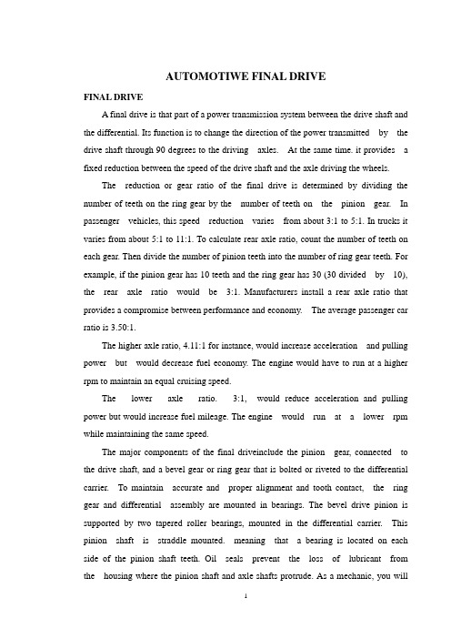
AUTOMOTIWE FINAL DRIVEFINAL DRIVEA final drive is that part of a power transmission system between the drive shaft and the differential. Its function is to change the direction of the power transmitted by the drive shaft through 90 degrees to the driving axles. At the same time. it provides a fixed reduction between the speed of the drive shaft and the axle driving the wheels.The reduction or gear ratio of the final drive is determined by dividing the number of teeth on the ring gear by the number of teeth on the pinion gear. In passenger vehicles, this speed reduction varies from about 3:1 to 5:1. In trucks it varies from about 5:1 to 11:1. To calculate rear axle ratio, count the number of teeth on each gear. Then divide the number of pinion teeth into the number of ring gear teeth. For example, if the pinion gear has 10 teeth and the ring gear has 30 (30 divided by 10), the rear axle ratio would be 3:1. Manufacturers install a rear axle ratio that provides a compromise between performance and economy. The average passenger car ratio is 3.50:1.The higher axle ratio, 4.11:1 for instance, would increase acceleration and pulling power but would decrease fuel economy. The engine would have to run at a higher rpm to maintain an equal cruising speed.The lower axle ratio. 3:1, would reduce acceleration and pulling power but would increase fuel mileage. The engine would run at a lower rpm while maintaining the same speed.The major components of the final driveinclude the pinion gear, connected to the drive shaft, and a bevel gear or ring gear that is bolted or riveted to the differential carrier. To maintain accurate and proper alignment and tooth contact, the ring gear and differential assembly are mounted in bearings. The bevel drive pinion is supported by two tapered roller bearings, mounted in the differential carrier. This pinion shaft is straddle mounted. meaning that a bearing is located on each side of the pinion shaft teeth. Oil seals prevent the loss of lubricant from the housing where the pinion shaft and axle shafts protrude. As a mechanic, you willencounter the final drive gears in the spiral bevel and hypoid design.Spiral Bevel GearSpiral bevel gears have curved gear teeth with the pinion and ring gear on the same center line. This type of final drive is used extensively in truck and occasionally in older automobiles. This design allows for constant contact between the ring gear and pinion. It also necessitates the use of heavy grade lubricants.Hypoid GearThe hypoid gear final drive is an improvement or variation of the spiral bevel design and is commonly used in light and medium trucks and all domestic rear- wheel drive automobiles. Hypoid gears have replaced spiral bevel gears because they lower the hump in the floor of the vehicle and improve gear-meshing action. As you can see in figure 5-13, the pinion meshes with the ring gear below the center line and is at a slight angle (less than 90 degrees).Figure 5-13.—Types of final drives.This angle and the use of heavier (larger) teeth permit an increased amount of power to be transmitted while the size of the ring gear and housing remain constant. The tooth design is similar to the spiral bevel but includes some of thecharacteristics of the worm gear. This permits the reduced drive angle. The hypoid gear teeth have a more pronounced curve and steeper angle, resulting in larger tooth areas and more teeth to be in contact at the same time. With more than one gear tooth in contact, a hypoid design increases gear life and reduces gear noise. The wiping action of the teeth causes heavy tooth pressure that requires the use of heavy grade lubricants.Double-Reduction Final DriveIn the final drives shown in figure 5-13, there is a single fixed gear reduction. This is the only gear reduction in most automobiles and light- and some medium-duty trucks between the drive shaft and the wheels.Double-reduction final drives are used for heavy- duty trucks. With this arrangement (fig. 5-14) it is not necessary to have a large ring gear to get the necessary gear reduction. The first gear reduction is obtained through a pinion and ring gear as the single fixed gear reduction final drive. Referring to figure 5-14, notice that the secondary pinion is mounted on the primary ring gear shaft. The second gear reduction is the result of the secondary pinion which is rigidly attached to the primary ring gear, driving a large helical gear which is attached to the differential case. Double-reduction final drives may be found on military design vehicles, such as the 5-ton truck. Many commercially designed vehicles of this size use a single- or double-reduction final drive with provisions for two speeds to be incorporatedFigure 5-14.—Double-reduction final driveTwo-Speed Final DriveThe two-speed or dual-ratio final drive is used to supplement the gearing of the other drive train components and is used in vehicles with a single drive axle (fig. 5-15). The operator can select the range or speed of this axle with a button on the shifting lever of the transmission or by a lever through linkageThe two-speed final drive doubles the number of gear ratios available for driving the vehicle under various load and road conditions. For example, a vehicle with a two-speed unit and a five-speed transmission, ten different forward speeds are available. This unit provides a gear ratio high enough to permit pulling a heavy load up steep grades and a low ratio to permit the vehicle to run at high speeds with a light load or no loadThe conventional spiral bevel pinion and ring gear drives the two-speed unit, but aplanetary gear train is placed between the differential drive ring gear and the differential case. The internal gear of the planetary gear train is bolted rigidly to the bevel drive gear. A ring on which the planetary gears are pivoted is bolted to the differential case. A member, consisting of the sun gear and a dog clutch, slides on one of the axle shafts and is controlled through a button or lever accessible to the operatorWhen in high range, the sun gear meshes with the internal teeth on the ring carrying the planetary gears and disengages the dog clutch from the left bearing adjusting ring, which is rigidly held in the differential carrier. In this position, the planetary gear train is locked together. There is no relative motion between the differential case and the gears in the planetary drive train. The differential case is driven directly by the differential ring gear, the same as in the conventional single fixed gear final drive.When shifted into low range, the sun gear is slid out of mesh with the ring carrying the planetary gears. The dog clutch makes a rigid connection with the left bearing adjusting ring. Because the sun gear is integral with the dog clutch, it is also locked to the bearing adjusting rings and remains stationary. The internal gear rotates the planetary gears around the stationary sun gear, and the differential case is driven by the ring on which the planetary gears are pivoted. This action produces the gear reduction, or low speed, of the axleDIFFERENTIAL ACTIONThe rear wheels of a vehicle do not always turn at the same speed. When the vehicle is turning or when tire diameters differ slightly, the rear wheels must rotate at different speeds.If there were a solid connection between each axle and the differential case, the tires would tend to slide, squeal, and wear whenever the operator turned the steering wheel of the vehicle. A differential is designed to prevent this problem.Driving Straight AheadWhen a vehicle is driving straight ahead, the ring gear, the differential case, the differential pinion gears, and the differential side gears turn as a unit. The two differential pinion gears do NOT rotate on the pinion shaft, because they exert equal force on the side gears. As a result, the side gears turn at the same speed as the ring gear, causing both rear wheels to turn at the same speed.Turning CornersWhen the vehicle begins to round a curve, the differential pinion gears rotate on the pinion shaft. This occurs because the pinion gears must walk around the slower turning differential side gear. Therefore, the pinion gears carry additional rotary motion to the faster turning outer wheel on the turn..Differential speed is considered to be 100 percent. The rotating action of the pinion gears carries 90 percent of this speed to the slowing mover inner wheel and sends 110 percent of the speed to the faster rotating outer wheel. This action allows the vehicle to make the turn without sliding or squealing the wheels.Figure 5-15.—Two speed final drive汽车主减速器主减速器主减速器是在传动轴和差速器之间的一个动力传动系统的组成部分。
机械原理术语英汉对照
机械原理重要名词术语中英文对照表Aarchimedes worm 阿基米德蜗杆BFifth-power polynomial motion 五次多项式运动规律oscillating follower 摆动从动件cam with oscillating follower 摆动从动件运动规律oscillating guide-bar mechanism 摆动导杆机构cycloidal gear 摆线齿轮cycloidal motion 摆线运动规律cycloidal-pin wheel 摆线针轮angle of contact 包角back cone 背锥back angle 背锥角back cone distance 背锥距scale 比例尺closed kinematic chain 闭式运动链closed chain mechanism 闭式链机构arm 臂部modified gear 变位齿轮modification coefficient 变位系数standard spur gear 标准直齿轮combine in parallel 并联式组合amount of unbalance 不平衡量intermittent gearing不完全齿轮wave generator 波发生器number of waves 波数Cgeneva wheel 槽轮geneva mechanism 槽轮机构groove cam 槽凸轮backlash 侧系differential gear train 差动轮系differential screw mechanism 差动螺旋机构differentials 差速器space 齿槽space width 齿槽宽addendum 齿顶高addendum circle 齿顶圆dedendum 齿根高dedendum circle 齿根圆thickness 齿厚circular pitch 齿距face width 齿宽tooth profile 齿廓tooth curve 齿廓曲线gear 齿轮pinion and rack 齿轮齿条机构pinion cutter 齿轮插刀hob,hobbing cutter 齿轮滚刀gears 齿轮机构blank 齿轮轮坯teeth number 齿数gear ratio 齿数比rack 齿条rack cutter 齿条插刀coincident points 重合点contact ratio 重合度transmission ratio, speed ratio 传动比transmission angle 传动角combine in series 串连式组合driven pulley 从动带轮driven link, follower 从动件width of flat-face 从动件平底宽度follower dwell 从动件停歇follower motion 从动件运动规律driven gear 从动轮Dbelt drives 带传动belt pulley 带轮universal joint 单万向联轴节unit vector 单位矢量equivalent spur gear 当量齿轮equivalent teeth number 当量齿数equivalent coefficient of friction 当量摩擦系数cutter 刀具lead 导程lead angle 导程角constant acceleration and deceleration motion 等加速等减速运动规律constant diameter cam等径凸轮constant breadth cam 等宽凸轮uniform motion, constant velocity motion等速运动规律equivalent link 等效构件equivalent force 等效力equivalent moment 等效力矩equivalent mass 等效质量equivalent moment of inertia 等效惯性力lower pair 低副clearance 顶隙ordinary gear train 定轴轮系dynamic balance 动平衡dynamic balancing machine 动平衡机dynamic characteristics 动态特性dynamic reaction 动压力dynamic load 动载荷transverse plane 端面transverse parameters 端面参数transverse circular pitch 端面齿距transverse contact ratio 端面重合度transverse module 端面模数transverse pressure angle 端面压力角inline roller follower对心滚子从动件inline flat-faced follower 对心平底从动件inline slider crank mechanism对心曲柄滑块机构in-line translating follower对心移动从动件polynomial motion 多项式运动规律rotor with several masses 多质量转子idler gear 惰轮Fgenerating line 发生线generating plane 发生面normal plane法面normal paramenters 法面参数normal circular pitch 法面齿距normal module 法面模数normal pressure angle 法面压力角feedback combining 反馈式组合inverse cam mechanism 反凸轮机构inverse (backward) kinematics 反向运动学kinematic inversion 反转法generating 范成法form cutting 仿形法flywheel飞轮moment of flywheel 飞轮距nonstandard gear非标准齿轮aperiodic speed fluctuation 非周期性速度波动noncircular gear非圆齿轮standard pitch line分度线standard pitch circle分度圆standard pitch cone分度圆锥planetary differential封闭差动轮系additional mechanism附加机构compound hinge 复合铰链compound combining复合式组合compound screw mechanism复式螺旋机构complex mechanism复杂机构Ginterference干涉rigid circular spline刚轮body guidance mechanism 刚体导引机构rigid impulse (shock) 刚性冲击rigid rotor 刚性转子higher pair高副grashoff’s law 格拉晓夫定理undercutting根切working space工作空间effective resistance工作阻力effective resistance moment工作阻力矩working stroke 工作行程common normal line 公法线general constraint公共约束metric gears公制齿轮power 功率conjugate profiles共轭齿廓conjugate cam共轭凸轮link 构件fixed link, frame 固定构件jointed manipulator关节型操作器inertia force惯性力partial balance of shaking force 惯性力部分平衡moment of inertia, shaking moment惯性力矩balance of shaking force 惯性力平衡full balance of shaking force 惯性力完全平衡path generator轨迹发生器hob,hobbing cutter滚刀roller滚子radius of roller 滚子半径roller follower 滚子从动件undercutting 过度切割Hfunction generator函数发生器interchangeable gears互换性齿轮slider 滑块return,return-stroke 回程compound gear train 复合轮系Jmechanism 机构analysis of mechanism机构分析balance of balance机构平衡mechanism机构学kinematic design of mechanism机构运动设计kinematic diagram 机构运动简图synthesis of mechanism机构综合constitution of mechanism机构组成frame,fixed link机架kinematic inversion 机架变换machine机器robot 机器人manipulator 机器人操作器robotics 机器人学machinery 机械dynamic analysis of machinery机械动力分析dynamic design of machinery 机械动力设计dynamics of machinery 机械动力学mechanical advantage机械利益balance of machinery 机械平衡manipulator机械手mechanical behavior 机械特性mechanical efficiency机械效率mechanisms and machine theory, theory of mechanisms and machines机械原理coefficient of speed fluctuation机械运转不均匀系数fundamental mechanism 基础机构base circle基圆radius of base circle 基圆半径base pitch 基圆齿距pressure angle of base circle 基圆压力角base cylinder 基圆柱base cone 基圆锥quick-return mechanism 急回机构quick-return characteristics 急回特性quick-return motion 急回运动ratchet棘轮ratchet mechanism棘轮机构pawl 棘爪extreme position极限位置crank angle between extreme positions 极位夹角computer aided design计算机辅助设计computer integrated manufacturing system 计算机集成制造系统acceleration加速度acceleration analysis加速度分析acceleration diagram 加速度曲线knife-edge follower尖底从动件intermittent motion mechanism 间歇运动机构simple harmonic motion (SHM for short) 简谐运动involute helicoid 渐开线螺旋面involute 渐开线involute profile 渐开线齿廓involute gear 渐开线齿轮generating line of involute 渐开线发生线involute equation 渐开线方程involute function 渐开线函数involute worm 渐开线蜗杆pressure angle of involute 渐开线压力角simple harmonic motion 简谐运动cross-belt drive交叉带传动crossed helical gears交错轴斜齿轮angular acceleration 角加速度angular velocity 角速度angular velocity ratio 角速比correcting plane校正平面structure 结构structural and mechanical error 结构误差pitch point 节点pitch line节线pitch circle 节园thickness on pitch circle 节园齿厚pitch diameter节圆直径pitch cone 节圆锥pitch cone angle节圆锥角analytical design 解析设计diametral pitch 径节clearance 径向间歇static balance 静平衡passive degree of freedom 局部自由度absolute motion 绝对运动absolute velocity 绝对速度load balancing mechanism 均衡装置Kopen-belt drive 开口传动open kinematic chain 开式链open chain mechanism 开式链机构spatial mechanism 空间机构spatial linkages 空间连杆机构spatial cams 空间凸轮机构spatial kinematic pair 空间运动副spatial kinematic chain 空间运动链block diagram 框图Lpitch curve 理论廓线force 力force polygon 力多边形force-closed cam mechanism 力封闭型凸轮机构moment 力矩equilibrium 力平衡couple [of forces], couples 力偶moment of couple 力偶矩connecting rod, couple 连杆linkages 连杆机构couple curve 连杆曲线line of centers 连心线chain wheel 链轮two-dimensional cam 两维凸轮critical speed 临界转速six-bar linkage 六杆机构blank 轮坯gear train 轮系screw 螺杆thread pitch 螺矩nut, screw nut螺母thread of a screw 螺纹helical pair 螺旋副screw mechanism 螺旋机构helical angle 螺旋角helix, helical line 螺旋线Mmodule 模数friction摩擦friction angle 摩擦角friction force 摩擦力friction moment 摩擦力矩coefficient of friction 摩擦系数friction circle 摩擦圆end-effector 末端执行器objective function 目标函数Nmechanism with flexible elements 挠性机构flexible rotor 挠性转子internal gear 内齿轮ring gear 内齿圈engaging-out啮出engagement, meshing engagement, meshing 啮合meshing point 啮合点angle of engagement 啮合角contacting line, pressure line, line of engagement 啮合线length of contacting line 啮合线长度engaging-in啮入nomogram诺模图Pdisk cam 盘形凸轮parabolic motion抛物线运动belt pulley 皮带轮offset distance 偏距offset circle 偏距圆eccentric 偏心盘offset roller follower 偏置滚子从动件offfser knife-edge follower 偏置尖底从动件offset flat-face follower 偏置平底从动件offset slider-crank mechanism 偏置曲柄滑块机构frequency频率flat belt drive 带传动flat-face follower 平底从动件face width 平底宽度balance 平衡balancing machine 平衡机balancing quality 平衡品质correcting plane 平衡平面balance mass, quality of mass 平衡质量counterweight 平衡重balancing speed 平衡转速planar pair, flat pair 平面副planar mechanism 平面机构planar kinematic pair 平面运动副planar linkage 平面连杆机构planar cam 平面凸轮parallel helical gears 平行轴斜齿轮Qother mechanism most in use 其它常用机构starting period 起动阶段pneumatic mechanism 气动机构singular position 奇异位置initial contact ,beginning of contact 起始啮合点forced vibration 强迫振动depth of cut 切齿深度crank 曲柄grashoff’s law曲柄存在条件rotation guide-bar mechanism 转动导杆机构slider-crank mechanism 曲柄滑块机构crank-rocker mechanism曲柄摇杆机构curvature曲率radius of curvature 曲率半径curved-shoe follower曲面从动件curve matching 曲线拼接driving force驱动力driving moment 驱动力矩whole depth全齿高spherical pair球面副spherical involute 球面渐开线spherical motion球面运动sphere-pin pair球销副polar coordinate manipulator球坐标操作器Rherringbone gear,double helical gear 人字齿轮redundant degree of freedom 冗余自由度flexspline 柔轮flexible impulse, soft shock 柔性冲击flexible manufacturing system 柔性制造系统flexible automation 柔性自动化Sthree-dimensional cam 三维凸轮kennedy’s theorem,theorem of three centers 三心定理planetary drive with small teeth difference 少齿差行星传动design variable 设计变量rise 升程cam profile 实际廓线real part 实部vector矢量output work输出功output link 输出构件output mechanism 输出机构output torque 输出力矩output shaft 输出轴input link 输入构件mathematical model 数学模型double-slider mechanism, ellipsograph 双滑块机构double crank mechanism 双曲柄机构constant-velocity universal joints 双万向联轴节double rocker mechanism 双摇杆机构oldham coupling 双转块机构instantaneous center 瞬心dead point 死点four-bar linkage 四杆机构velocity 速度speed fluctuation 速度波动coefficient of speed fluctuation 速度波动系数velocity diagram 速度曲线instantaneous center of velocity 速度瞬心Tstep pulley 塔轮sun gear 太阳轮characteristics 特性equivalent mechanism 替代机构governor调速器stopping phase 停车阶段dwell 停歇synchronous belt drive同步带传动cam 凸轮cams, cam mechanism 凸轮机构cam profile 凸轮(实际)廓线layout of cam profile 凸轮廓线绘制pitch curve 凸轮理论廓线graphical design 图解设计rise 推程Wexternal gear 外齿轮external force 外力universal joint, hooke’s coupling 万向联轴节wrist 腕部reciprocating motion 往复移动differential screw mechanism 差动螺旋机构displacement 位移displacement diagram 位移曲线pose, position and orientation 位姿steady motion period 稳定运转阶段robust design 稳健设计worm 蜗杆worm gearing 蜗杆传动机构number of threads 蜗杆头数diametral quotient 蜗杆直径系数worm and worm gear 蜗杆蜗轮机构worm gear 蜗轮Xcrank arm, planet carrier 系杆field balancing 现场平衡centrifugal force 离心力relative velocity 相对速度relative motion 相对运动pinion 小齿轮harmonic drive 谐波传动helical gear 斜齿圆柱齿轮stroke 工作行程coefficient of travel speed variation, advance-to return-time ratio 行程速比系数planet gear 行星轮planet gear train行星轮系planet carrier 行星架form-closed cam mechanism 形封闭凸轮机构virtual reality 虚拟现实redundant constraint 虚约束imaginary part 虚部allowable amount of unbalance 许用不平衡量allowable pressure angle 许用压力角circulating power load 循环功率流Ypressure angle 压力角jacobi matrix 雅克比矩阵rocker 摇杆hydrodynamic drive 液力传动hydraulic mechanism 液压机构reciprocating follower 移动从动件sliding pair, prismatic pair移动副prismatic joint 移动关节wedge cam 移动凸轮increment or decrement work 盈亏功optimal design 优化设计detrimental resistance有害阻力simple harmonic motion 余弦加速度运动round belt drive 圆带传动circular gear 圆形齿轮cylindric pair 圆柱副cylindrical cam 圆柱凸轮cylindrical worm 圆柱蜗杆cylindrical coordinate manipulator 圆柱坐标操作器bevel gears 圆锥齿轮机构cone angle 圆锥角driving link 原动件constraint 约束constraint condition 约束条件jerk 跃度jerk diagram 跃度曲线kinematic inversion 运动倒置kinematic analysis 运动分析kinematic pair 运动副moving link 运动构件kinematic diagram 运动简图kinematic chain 运动链motion skewness 运动失真kinematic design 运动设计cycle of motion 运动周期kinematic synthesis 运动综合coefficient of velocity fluctuation 运动不均匀系数Zload 载荷generating 展成法,范成法tension pulley 张紧轮vibration 振动shaking couple 振动力矩frequency of vibration 振动频率amplitude of vibration 振幅tangent mechanism正切机构direct (forward ) kinematics 正向运动学sine generator, scotch yoke 正弦机构spur gear 直齿圆柱齿轮cartesian coordinate manipulator 直角坐标操作器diametral quotient 直径系数mass-radius product 质径积mid-plane 中间平面center distance 中心距center distance change 中心距变动central gear 中心轮final contact,end of contact 终止啮合点periodic speed fluctuation 周期性速度波动epicyclic gear train 周转轮系toggle mechanism 肘形机构shaft angle 轴角axial thrust load 轴向分力driving gear 主动齿轮driving pulley主动带轮rotating guide-bar mechanism 转动导杆机构revolute pair 转动副revolute joint 转动关节rotor 转子balance of rotor 转子平衡assembly condition 装配条件bevel gear 锥齿轮common apex of cone 锥顶cone distance 锥距cone pulley 锥轮sub-mechanism 子机构automation 自动化self-locking 自锁degree of freedom (dof for short )自由度total contact ratio 总重合度resultant force 总反力overlap contact ratio 纵向重合度combined mechanism 组合机构minimum teeth number 最少齿数minimum radius 最小向径applied force 作用力coordinate frame 坐标系。
汽车主减速器外文文献翻译、中英文翻译、外文翻译
汽车主减速器外文文献翻译、中英文翻译、外文翻译XXX Final DriveA final drive is an essential component of a power XXX primary n is to change the n of the power transmitted by the drive shaft by 90 degrees to the driving axles。
nally。
it provides a fixedn een the speed of the drive shaft and the axle that drives the wheels.The final drive is XXX power from the engine to the wheels。
allowing the vehicle to move。
It is composed of several XXX tothe wheels。
The final drive。
determines the number of ns the wheels make for each n of the engine.There are two types of final drives: the live axle and the independent XXX to the wheels。
while the independent XXX tothe wheels through a series of CV joints and half-shafts.In n。
the final drive is a XXX of power from the engine to the wheels。
It is essential to maintain and service the final drive XXX.The gear。
外文翻译--行星齿轮固有频率-精品
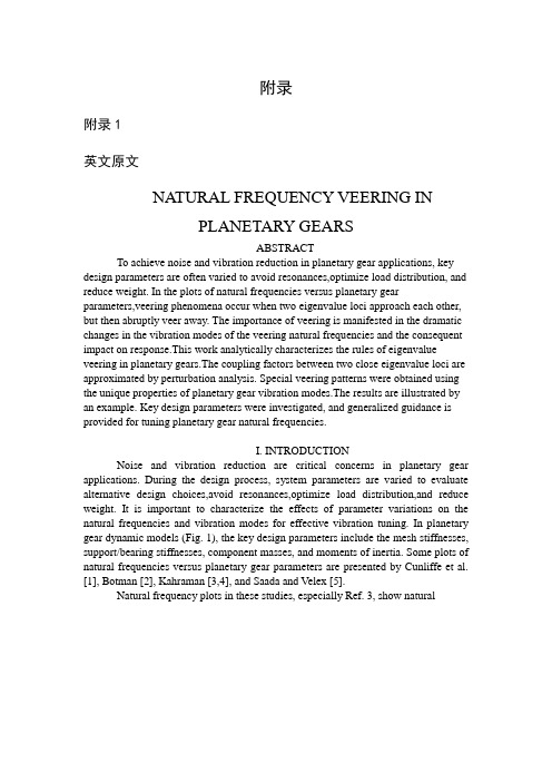
附录附录1英文原文NATURAL FREQUENCY VEERING INPLANETARY GEARSABSTRACTTo achieve noise and vibration reduction in planetary gear applications, key design parameters are often varied to avoid resonances,optimize load distribution, and reduce weight. In the plots of natural frequencies versus planetary gear parameters,veering phenomena occur when two eigenvalue loci approach each other, but then abruptly veer away. The importance of veering is manifested in the dramatic changes in the vibration modes of the veering natural frequencies and the consequent impact on response.This work analytically characterizes the rules of eigenvalue veering in planetary gears.The coupling factors between two close eigenvalue loci are approximated by perturbation analysis. Special veering patterns were obtained using the unique properties of planetary gear vibration modes.The results are illustrated by an example. Key design parameters were investigated, and generalized guidance is provided for tuning planetary gear natural frequencies.I. INTRODUCTIONNoise and vibration reduction are critical concerns in planetary gear applications. During the design process, system parameters are varied to evaluate alternative design choices,avoid resonances,optimize load distribution,and reduce weight. It is important to characterize the effects of parameter variations on the natural frequencies and vibration modes for effective vibration tuning. In planetary gear dynamic models (Fig. 1), the key design parameters include the mesh stiffnesses, support/bearing stiffnesses, component masses, and moments of inertia. Some plots of natural frequencies versus planetary gear parameters are presented by Cunliffe et al.[1], Botman [2], Kahraman [3,4], and Saada and Velex [5].Natural frequency plots in these studies, especially Ref. 3, show naturalfrequency veering phenomena when two eigenvalue loci approach each other as a parameter is varied, but then abruptly veer away like two similar charges repelling (point B in Fig. 2a). The vibration modes of the veering eigenvalues are strongly coupled and undergo dramatic changes in the veering neighborhood.The phenomenon has been studied extensively [6–9], but it has not been explored in planetary gears.Eigenvalue veering is also related to mode localization that can occur when disorder is introduced into nominally symmetric systems like turbine blades, space antennae, multispan beams, and other structures [6]. In the case of especially sharp veering, it is sometimes difficult to distinguish between intersection and veering just by observing eigenvalue plots.Curve veering/crossing complexity obstructs the tracing of eigenvalue loci under parameter changes. Also, when multiple curves veer or intersect close together (Fig. 3), strong modal coupling and the associated operating condition response changes that occur are not identifiable from frequency loci plots.The objectives of this work were twofold. The first was to analytically derive simple rules that predict eigenvalue veering in planetary gears. The second was to use the veering results, along with previously developed modal properties and eigensensitivity analysis, to define more fully the influence of model parameters on free vibration and to give guidance for tuning natural frequencies.Lin and Parker [10,11] analytically characterized the unique, highly structured properties of planetary gear natural frequency spectra and vibration modes. They also provided simple, closed-form expressions for the sensitivities of natural frequencies and vibration modes to design parameters [12]. These analytical results provide the necessary foundation for the present study of veering rules in planetary gears. The veering rules yield concrete conclusions expressed in simple forms for when two approachingeigenvalues veer or cross. The importance of the veering rules is to identify thoseranges in which small changes in design parameters can dramatically change the vibration modes and consequently the response. The results are illustrated on a benchmark planetary gear(the model parameters and natural frequencies are given in Tables 1 and 2,respectively) used in a helicopter power train.The lumped parameter model derived in Ref. 10 is used here. The model is applicable for general epicyclic gears with N planets. Each component has two translational and one rotational degree of freedom (DOF) in planar motion,so the system has L=3(N-3) DOF. Numerical results presented are for fixedring configurations, and L=3(N-2) in this case. The associated eigenvalue problem isII. VEERING/CROSSING CRITERIONA method for detecting eigenvalue veering/crossing in general dynamic systems is introduced here. PointB in Fig. 2a is an example of veering. When two eigenvalue loci veer away, their loci curvatures indicate the abruptness of curve direction changes. Perkins and Mote [7] proposed a veering/crossing criterion by estimating the locicurvature in the veering neighborhood for distinct eigenvalues. Let r and λs be two eigenvalues approaching each other around point B as a parameter ρis varied. The unperturbed eigensolutions at B are (λr,Φr) and (λs,Φs). Applying Taylor expansion around B, the eigenvalue loci are approximated bywhere is a small perturbation of the varyingparameter;λ'=∂λ/∂ρ;λ''=.The second derivatives λ''r andλ''s represent the curvatures of the loci.If λ''r =λ''s=0, these two loci are locally independent and free to cross each other. Ifλ''r , λ''s ≠0, the loci diverge and veering occurs. Largerλ''indicates sharper changes of the loci and stronger veering. For a distinct eigenvalueλr,the eigenvalue derivatives areIn the veering vicinity whereλr≈λs, λ''r andλ''s are dominated by terms with a small denominator, that is,The coupling factors χr and χs approximate the local curvatures. They are used to estimate veering strength.Figure 2b shows χ=χ14=χ18 versus the varying parameter ksp for the veering loci ω14 and ω18 in Fig. 2a. Notice the sharply changing vibration modes indicated in Fig. 2b. The two veering loci exchange mode shapes from points A to C, even though the loci do not intersect. The modes are strongly coupled at B and do not look like either of the veering modes just outside the veering zone. When the parameter is adjusted in the veering zone, the drastic changes in the vibration modes can have a great impact on the operating condition dynamic response, tooth loads, load sharing, and bearing forces and possibly lead to mode localization. The degree to which individual modes are excited by dynamic mesh forces (i.e., the modal forces) also changes dramatically as veering alters the modes.This veering criterion can be generalized to the case whenλs…λs m-1 are degenerate with multiplicity m.The second derivatives of these eigenvalues are [14]where the summation index k=1,…L, but k ≠s,…, s m-1. When another distinct eigenvalue λr is close to the degenerate λi, the dominant terms in Eqs. 5 and 3 areIf λr …λr n-1 is also degenerate, the coupling factors areIf the coupling factors are all zero, λr andλs loci cross; otherwise, veering occurs. This is the condition we examine below.III. VEERING PATTERNS IN PLANETARY GEARSWhen applied to planetary (or any epicyclic) gears, the above results reduce to particularly simple forms because of the unique structure of the vibration modes. All planetary gear vibration modes can be classified as one of the following types under the assumption of cyclic symmetry between the planets [10].The analysis is restricted to this commonly used class of epicyclic gears.1. Six rotational modes with distinct natural frequencies. They have pure rotation of the carrier, ring, and sun, that is, xh =yh =0, h=c, r, s. All planets have the same deflection2. Six pairs of translational modes with degenerate natural frequencies of multiplicity two. They have pure translation of the carrier, ring,and sun, that is, uh =0, h=c, r, s. For a pair of orthonormal translational modes Φi=and=Φj=(MΦj=0),,where the superscripts i and j indicate the modes Φi and Φj,respectively. The planet deflections have the relationwhere ψn=2(n1)/N for equally spaced planets.3. Three groups of planet modes with degenerate natural frequencies of multiplicity N 3. They have no motion of the carrier, ring, and sun,that is, xh=yh=uh=0, h=c,r, s.The planet deflections are related byWhere wn are N 3 independent sets of scalars satisfying nsinψn,ncosψn,n=0Two approaching planetary gear loci can be associated with any of the above three types of modes. Five cases of potential veering are examined below. The unique modal properties of Eqs. 10–12 were used to analyze the veering patterns. For concreteness, let the sun-planet mesh stiffness ksp be the varying parameter (Fig. 1) and M'=0.Case 1. Two rotational mode loci λr and λs. Rotational modes have distinct eigenvalues, and their second derivative with respect to ksp is [12]where δsn yscos(ψn αs) xssin(ψn αs) ηncosαs ζnsinαs us un is the modal deflection of the spring representing the nth sun-planet mesh stiffness; αs is the pressure angle of the sun-planet mesh; and the superscripts r and k in δsn indicate vibration modes ϕr and ϕk, respectively. The modal strain energy in the nth sun-planet mesh is δ'sn=ksp/2. The rotational modeproperty of Eq. 10 results in ,.The coupling factors of Eq. 4 are the dominant terms in Eq. 13(14)If ,then χr, χs 0, and the approaching eigenvalue loci veer away.Ifor, then χr=χs=0, and the loci cross each other. This requires that allstrain energy in the sun-planet meshes Usn 0 for vibration mode r or ϕs. However, all rotational modes except the rigid body mode must have strain energy in the sun-planet meshes. Therefore, two rotational mode loci (e.g., ω14 and ω18 in Fig. 2a) always veer away and do not intersect. Also, more strain energy in the sun-planet meshes means larger χr and χs and sharper veering. Both loci have comparable curvatures, as indicated by χr -χs; this is typical of results to follow as well.Case 2. Two translational mode loci λr=λp and λs =λq. Reducing Eq. 5 using the properties of translational modes, the derivatives λ''r andλ''p have the same form as Eq. 13, except the summation index k =1, …,L, but k≠r, p. The coupling factors of Eqs. 8 and 9 are the dominant terms inλ'':The translational mode property of Eq. 11 leads to the relationsUse of Eq. 17 in Eqs. 15 and 16 yieldsVanishing of the coupling factors (that is, loci crossing) requiresor=0 for all n. Physically, this implies no strain energy in any sun-planet meshes for the translational mode pairs (ϕr,ϕp) and (ϕs,ϕq). This does not occur,and the loci always veer away with strength determined byχr and χs (e.g., ω12,13and ω16,17 in Fig. 2a).Case 3. A rotational mode locus λr and a translational mode l ocus λs λq.From Eqs.6and7,the coupling factors areRecalling and Eq. 17, χs=χq=χr=0 is automatically satisfiedbecauseψn,ψn0. Note there is no condition on any δsn, which is different from the above cases. A rotational mode locus always crosses a pair oftranslational mode loci without veering. By similar analyses, planet mode loci always cross rotational and translational mode loci.Case 4. Two planet mode loci λr =λr m-1 and s=λs m-1 with multiplicity =3(N -3). The second derivatives of λr, …λr m 1 have the form of Eq. 13, except the summation index k =1,…L, but k≠r,… , r m-1. The coupling factors of Eqs. 8 and 9 areVEERING IN PLANETARY GEARSEquating these coupling factors to zero yields the conditions for the absence of curve veering:Using the planet mode property of Eq. 12, the sun-planet mesh deformations are related by and .Equation 22 resultsin0,i=r, …,r m-1 or 0, j =s, …, s=m-1. Physically, these conditions require that one set of degenerate planet modes have no strain energy in the sun-planet meshes. This does not occur, in general. Therefore, the coupling factors of two planet modes are nonzero, and their loci veer away (e.g., ω11 and ω15 in Fig. 2a), except for the special case discussed below.Case 5. Two decoupled planet mode loci approach each other as kp, mp,or Ip is varied. For the case when ksp krp and the pressure angle αr=αs=α, the three planet modes have additional properties besides Eq. 12 and can be further classified as follows [10]: (1) mode P1 only has planet tangential motion ηn (ζn=un=0); (2) mode P2 has no tangential motion (ηn=0), and planet radial motion is dominant (ζn=un); (3) mode P3 has no tangential motion (ηn=0),and planet rotation is dominant (ζn=un). Note planet mode P1 always decouples from P2 and P3. If the pressure angle α=0, modes P2 and P3 also decouple, that is, u=0 in P2 and ζn=0 in P3. With these additional properties, two decoupled planet mode loci can intersect. As an example, kp is taken as the varying parameter. The second derivative of a degenerate planet mode eigenvalue λr…λr m-1 is [12]where the summation index k=1,…, L, but k ≠r,…, r m- 1. The coupling factors areIf λr is of type P1 andλs is of type P2 or P3, then χr χs 0 is guaranteed because=0, i =r,… r m-1 and =0, j=s,… s m-1. So the mode P1 locus crosses the P2 and P3 loci (e.g., ω11 and ω15 intersect in Fig. 3 where ksp krp andαr αs). However, the mode P2 and P3 loci (ω5 and ω15 in Fig. 3) veer away because they are coupled when α≠0. If the conditions ksp =krp and αr=αs are not satisfied, the three coupled planet modes veer away as discussed in case 4. The above analysis (cases 1–4) uses ksp as the varying parameter and shows that two eigenvalue loci of the same mode type veer away and two loci of different mode types intersect with each other. This pattern is generally valid when other parameters (either stiffness or inertia) are varied. For changing stiffness (ksp, krp, kp, kh, khu, h=c, r, s), the eigenvalue derivatives are related to the deflections δin the springs representing the stiffness [12]. If two loci have the same mode types, as in cases 1, 2, and 4 above, the coupling factor χ=0 always requires the corresponding deflectionδ=0 in the vibration modes. This requirement is unlikely to be satisfied except for the special situation discussed in case5. Thus, χ≠0 for two close loci of the same type and veering occurs. If two loci belong to different mode types as in case 3, χ=0 is automatically satisfied due to the modal properties of Eps. 10–12, and the loci always intersect. For changing inertia (mh, Ih, h=c, r, s, p), the analysis is similar to that for stiffness. The general veering/crossing patterns are summarized in Table 3 and are apparent in the example of Fig. 4 (in which the parameters are different from those in Fig. 2).IV. APPLICATIONThe veering patterns help trace the evolution of eigenvalue loci and identify the effects of design parameters on planetary gear vibration. The planetary gear in a helicopter power train is used as an example. The nominal model parameters are given in Table 1. Table 2 identifies the mode type and where the dominant strain energy is in each mode. The natural frequencies are numbered at the nominal conditions (indicated by the dashed lines in Figs. 2–7).Mesh stiffnesses ksp and krp (Figs. 2 and 5) have little influence on the lownatural frequencies ω1 ~ ω10. This is because these modes are governed by bearing stiffnesses (Table 2) that are much smaller than the mesh stiffnesses. Modes 15–18 have large strain energy in the sun-planet meshes and are affected by ksp (Fig.2); modes 11–14 have substantial strain energy in the ring-planet meshes and are affected by krp (Fig. 5). When ksp is reduced from the nominal value, the changingω15 to ω18 approach the 11 to ω14 loci. Because loci of the same type cannot intersect, veering occurs between rotational modes 18 and 14, translational mode pairs (16,17) and (12,13), and planet modes 15 and 11. Below the veering zones (ksp 100N/μm), modes 11 to 14 are very similar to modes 15 to 18 above the veering zones (ksp 800N/μm). In the same way, one can predict the trend of frequency loci as krp is increased (Fig. 5).Support stiffnesses kh, khu, and h c, r, s of the carrier, ring, and sun, respectively, can vary over a wide range depending on the configuration (fixing or floating these components). Rotational and planet modes are independent of the transverse support stiffness kh because they have no translation of the carrier,ring, and sun: only translational modes are affected by changes in kh (Figs. 6a,6b). When the rotational support stiffnesses khu are altered, similar results are obtained (Figs. 6c, 6d), except it is the rotational modes that are susceptible to khu variations.Altering planet parameters affects most natural frequencies as all modes generally involve planet deflections. Applying the derived veering results, five pairs of veering are identified for changing planet bearing stiffness in Fig. 3: rotational modes 8 and 18, 4 and 14; translational modes (9,10) and (16,17),(6,7) and (12,13); and planet modes 5 and 15. For large stiffness kp 5000N/ m, eight natural frequencies increase rapidly to outside the range of interest.Planet mass mp and moment of inertia Ip also have significant influence on the natural frequencies (Fig. 7).V. DISCUSSION AND SUMMARYThe planets can be unequally spaced in planetary gear applications. For Planetarygears with planet position angles ψn satisfyingψnψn0, the vibration modes retain structured properties [11]: 6 distinct rotational modes, 12 distinct translational modes, and 3 planet modes with multiplicity N-3. The translational modes become distinct because of the loss of cyclic symmetry. Under these conditions, the veering patterns in Table 3 still apply,although the analytical loci curvatures have a more complicated form. A practically important case has diametrically opposed planets with position angles ψn N/2 ψn π. Figure 8 shows a four-planet example with ψn=0,82,180,262,whileψnψn0 other parameters remain the same as in prior figures. Translational modes 9 and 10, which are degenerate for equal planet spacing, cross the rotational mode 8, but veer away from translational modes 16 and 17. When planetsare arbitrarily spaced, the vibration modes lose the structured properties of Eqs.10–12, so the derived veering patterns are not valid.Eigenvalue loci veering also occurs when degenerate modes of a symmetric system are separated by small disorders. In planetary gears, the cyclic symmetry can be broken by differing mesh stiffnesses at each planet mesh, manufacturing variations, and assembly errors. For cyclically symmetric or periodic systems with small disorders and weak structural coupling, mode localization often accompanies eigenvalue loci veering [6]. Planetary gears have relatively strong coupling between the planets through the carrier and teeth meshes, so sharp mode localization is unlikely even in the presence of loci veering. Afterexamination of many cases with various configurations and parameters, we have not found a realistic example of mode localization in planetary gears.The special veering patterns of planetary gear eigenvalue loci are easily summarized. Two approaching eigenvalue loci of the same type (rotational mode, translational mode, and planet mode) veer away, while two loci of different mode types cross each other. The mode shapes are exchanged across the veering zone. In the veering zone, the modes are strongly coupled and markedly different from outside the zone. One can expect significant differences in response from these changed modes. These rules result from the unique modal properties of the planetary gears and apply to all design parameters. The characterized veering patterns, combined with the unique modal properties and the eigensensitivity analysis, provide considerable insight into planetary gear free vibration.The effects of key design parameters are summarized below:1. Mesh stiffness. ksp and krp each control three different natural frequencies associated with one rotational mode, one pair of translational modes, and one group of planet modes. Dominant strain energy occurs in the tooth meshes of these vibration modes.2. Carrier, ring, and sun parameters. kh and khu, h=c, r, s, each affect only one natural frequency. The transverse stiffness kh controls one pair of translational modes, and the torsional stiffness khu controls one rotational mode. Floating or fixing the carrier, ring, or sun has limited influence on planetary gear modal properties. The carrier, ring, and sun masses and moments of inertia affect the same frequencies as their corresponding support stiffness, although the frequencies vary in the opposite direction.3. Planet parameters. Planet bearing stiffness and planet inertia are the most influential parameters and affect most natural frequencies. A stiff planet bearing can be beneficial for resonance tuning because it substantially reduces the number of natural frequencies in the lower frequency range that is commonly of most interest.英文翻译行星齿轮固有频率摘要在行星齿轮的应用中为了减少噪音和振动的,主要设计参数往往是不同的,以避免共振,优化负荷分配,降低重量。
基本的螺旋锥齿轮中英3文翻译
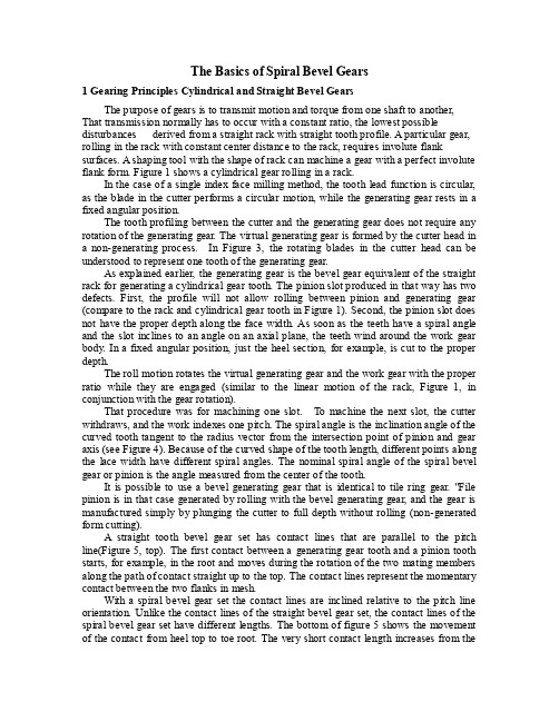
The Basics of Spiral Bevel Gears1 Gearing Principles Cylindrical and Straight Bevel GearsThe purpose of gears is to transmit motion and torque from one shaft to another, That transmission normally has to occur with a constant ratio, the lowest possible disturbances derived from a straight rack with straight tooth profile. A particular gear, rolling in the rack with constant center distance to the rack, requires involute flank surfaces. A shaping tool with the shape of rack can machine a gear with a perfect involute flank form. Figure 1 shows a cylindrical gear rolling in a rack.In the case of a single index face milling method, the tooth lead function is circular, as the blade in the cutter performs a circular motion, while the generating gear rests in a fixed angular position.The tooth profiling between the cutter and the generating gear does not require any rotation of the generating gear. The virtual generating gear is formed by the cutter head in a non-generating process. In Figure 3, the rotating blades in the cutter head can be understood to represent one tooth of the generating gear.As explained earlier, the generating gear is the bevel gear equivalent of the straight rack for generating a cylindrical gear tooth. The pinion slot produced in that way has two defects. First, the profile will not allow rolling between pinion and generating gear (compare to the rack and cylindrical gear tooth in Figure 1). Second, the pinion slot does not have the proper depth along the face width. As soon as the teeth have a spiral angle and the slot inclines to an angle on an axial plane, the teeth wind around the work gear body. In a fixed angular position, just the heel section, for example, is cut to the proper depth.The roll motion rotates the virtual generating gear and the work gear with the proper ratio while they are engaged (similar to the linear motion of the rack, Figure 1, in conjunction with the gear rotation).That procedure was for machining one slot. To machine the next slot, the cutter withdraws, and the work indexes one pitch. The spiral angle is the inclination angle of the curved tooth tangent to the radius vector from the intersection point of pinion and gear axis (see Figure 4). Because of the curved shape of the tooth length, different points along the lace width have different spiral angles. The nominal spiral angle of the spiral bevel gear or pinion is the angle measured from the center of the tooth.It is possible to use a bevel generating gear that is identical to tile ring gear. "File pinion is in that case generated by rolling with the bevel generating gear, and the gear is manufactured simply by plunging the cutter to full depth without rolling (non-generated form cutting).A straight tooth bevel gear set has contact lines that are parallel to the pitch line(Figure 5, top). The first contact between a generating gear tooth and a pinion tooth starts, for example, in the root and moves during the rotation of the two mating members along the path of contact straight up to the top. The contact lines represent the momentary contact between the two flanks in mesh.With a spiral bevel gear set the contact lines are inclined relative to the pitch line orientation. Unlike the contact lines of the straight bevel gear set, the contact lines of the spiral bevel gear set have different lengths. The bottom of figure 5 shows the movement of the contact from heel top to toe root. The very short contact length increases from thebeginning of the roll towards the center of the face width and reduces as the roll approaches the exit at the toe end.The contact lines between pinion and generating gear are identical to the contact lines between cutter blades and pinion flanks.2 Single Index Process-- Face MillingIn a single index process, just one slot is cut at a time. For the non-generated member only, the cutter rotates and is fed into the work gear to the full depth. After reaching the full depth, the cutter withdraws and the work indexes one pitch to the next desired slot position (Figure 6, right side). The process repeats until all slots have been machined. The resulting flank lead function is a circular arc.Machining a generated member is done by plunging at the heel roll position first. After plunging, the roll motion begins, and generating of the flanks from heel to toe occurs. The flank lead function for a face milled, generated gear is a circular arc that is wound around a conical surface.The manufacturing .of a face milled bevel gear pair is possible in a five-cut process or in a completing process. The five-cut process consists of the following five independent operations:1. Gear roughing (alternate roughing blades),2. Gear finishing (alternate finishing blades),3. Pinion roughing (alternate roughing blades),4. Pinion finishing convex (inner blades only), and5. Pinion finishing concave (outer blades only).A completing process uses two combined operations:1. Gear roughing and finishing (alternate roughing finishing blades) and2. Pinion roughing and finishing (alternate roughing finishing blades).3 Continuous Indexing Process--Face HobbingA continuous cutting process consists of continuous rotations and a feed motion only. While an outer and an inner blade move through a slot of the work gear, the work gear is rotating in the opposite direction, The relation of the cutter rpm and the work rotation is equivalent to the ratio between the number of work gear teeth and the number cutter head blade groups (starts). The resulting flank lead function is an epicycloid. The effective cutting direction of the blades in the cutter head is not perpendicular to the cutter radius vector (like in the single indexing process). The blades are moved in the cutter head tangentially to an offset position to accommodate the correct orientation with respect to the cutting motion vector. The pitch points on the cutting edge of inner and outer blade have an identical radius. The right slot width is achieved with the angular distance between the outer blade (first) and the following inner blade. The left portion of Figure 6 shows the kinematic relationship and the orientation of the blades relative to cutter and cutting motion.Balancing of the tooth thicknesses between pinion and gear can only be realized by different radii of inner and outer blade pitch points, since the spacing between the blades is given by the cutter head design and therefore remains constant.While one blade group (like shown in Figure 6) is moving through one slot, the work rotates in the opposite direction, such that the next blade group enters the next slot. That way, all the slots around the work gear are cut at about the same time. The feedmotion to feed the critter to the full depth position is therefore slower than in the single index process.A non-generated work gear is finished when the full depth position is reached. To get the highest possible spacing accuracy, a dwell time is applied to the non-generated member. The aim of the dwell motion is to allow each blade to move once more to each slot, which takes N slots to pass by, where N is the number of cutter starts times the number of .gear teeth. N is equivalent to as many ring gear revolutions as the cutter has starts.For a generated pinion, a roll motion follows the plunging cycle in the center, roll position (the cutter does not cut the full depth yet). The roll motion after plunging moves the cutting action to the heel; both plunging and rolling to heel is part of the roughing cycle. At the heel roll position, the cutter advances to the full depth position, the cutter rpm increases to a finishing surface speed, and a slow roll motion from heel to toe follows. When arriving at the toe (end roll position), all teeth of the generated work gear or pinion are finished (see Figure 7).4 Heat Treatment of Bevel GearsHeat treatment follows the soft cutting operation. The generally used low carbon steel has to be carburized on the surface, by case hardening for example. The heat treatment is finished with the quenching operation that provides a surface hardness in the range of 60 to 63 Rc (Rockwell C).The pinion may be 3 Rc harder than the ring gear to equalize the wear and reduce the risk of scoring.The core material stays softer and more ductile,with a hardness in the range of 30 to 40 Rc.The distortions from heat treatment are critical to the final hard finishing operation.The kind of heat treatment facility(salt bath,furnace or continuous furnace),as well as the differences between the charges of blank material,has a significant influence On the gear distortion.The gear, which is mostly shaped like a ring,loses its flatness(it gets a face run-out).via the hardening procedure.The pinion,in most cases,is shaped like a long shaft that loses its straightness(radial run—out).In addition to the blank body distortions,heat treating causes a distortion of the individual teeth.The spiral angle changes,the flank length curvature is reduced and the pressure angle changes.To achieve the best results,attention has to be paid to processing and handling of the parts through the furnace.5 Hard Finishing of Bevel GearsThe final machining operation after heat treatment should provide a good surface finish and remove flank distortions. The most common process used is lapping. Pinion and gear are brought into mesh and rolled under light torque. To provide an abrasive action, a mixture of oil and silicon carbide is poured between the teeth (Figure 8). A relative movement of pinion and gear along their axes and a movement in offset direction is created, such that the contact area moves from toe to heel and back numerous times.The lapping process improves the surface finish,leaves a desirable micro-structure on the flank surfaces and removes heat treat distortions to some extent. The metal removal is not uniform in the different flank sections and varies from set to set, since the pinion and gear are used as tools to hard finish each other. This is the reason why lappedsets have to be built as a pair; lapped pinions and gears are not interchangeable.The lapping surface structure is not oriented in the direction of the contact lines, thus providing a good hydrodynamic oil film between the contact areas. The lapping structure also tends to deliver side bands in a noise frequency analysis, which makes the gear set appear to roll more quietly.During the lapping process, a pinion and a gear are always machined and finished at the same time. The time to lap a pair is equal to or shorter than the time to machine one member using another finishing method. Therefore, lapping is often called the most economical bevel gear finishing process.Another finishing option is grinding of bevel gears, which is limited to face milled (single index) bevel gears. The grinding wheel envelops a single side or an alternate completing cutter (Figure 9).Today's technology does not allow the use of a grinding tool in a continuous indexing process. The advantage of grinding is the manufacturing of an accurate flank surface with a predetermined topography. The process allows the constantly repeated production of equal pans. Building in pairs is not necessary.Lapped pairs used in vehicles require an oil change after the first 1,000 miles because of abrasive particles introduced to the tooth surfaces during lapping. A further advantage of grinding over lapping is that such an oil change is unnecessary with ground spiral bevel gears.A process between lapping and grinding with respect to surface speed and relative motion is honing. Honing trials on bevel gears have been done, but they haven't been proven successful.Skiving is a hard cutting process. A tool material such as carbide or boron carbonitride is used on tile cutting edge. The cutting machine setup is identical to that for soft machining. The blade point dimension is wider than the one for soft cutting, such that a 0.005-inch uniform stock removal per flank takes place. Skiving delivers a high quality part accuracy and a fine surface finish. Skiving is applied to small batches of mostly larger gear sets, The advantage of skiving is the use of the same cutter head (only with different blades) and the possible use of the same cutting machine. That makes the investment in machines and tools a minimum.6 Some Bevel Gear ConventionsThe expression "bevel gears" is used as a general description for straight and spiral bevel gears as well as hypoid gear sets. If the axes of the pinion and gear do not intersect but have a distance in space, the gear set is called a hypoid gear set. The name is derived from the hyperbolic shape of the "pitch cones." For simplification, the blanks are still manufactured with a conical shape.The convex gear flank rolls with the concave pinion flank. This pair of flanks is called the "drive side." The direction of rotation where those flanks contact the pinion drives is called the drive direction. The drive side direction is always used in vehicles to drive the vehicle forward. The reverse direction is subsequently called the coast side (vehicle rolls downhill, foot is off the gas pedal, wheels drive the engine). In some cases, the coast side is used to drive the vehicle, but it is still called the coast side.Ease-off is the presentation of flank form corrections applied to pinion and/or gear. The ease-off topography in defined in the ring gear coordinate system, regardless of where the corrections were done (pinion, gear or both).Protuberance is a profile relief in the root area of the flank, which prevents flankdamage resulting from "digging in" of the mating tooth's top edge. Protuberance is realized with a cutting blade modification.7 Localized Tooth ContactWhen bevel gear sets are cut according to the crown gear or generating gear principle, the result is a conjugate pair of gears. Conjugate means pinion and gear have a line contact in each angular position. While rotating the gear in mesh, the contact line moves from heel top to toe root. The motion transmission happens in each roll position with precisely the same constant ratio. Roll testing is done in specially designed bevel gear test machines. If a marking compound (paint) is brushed onto the flanks of the ring gear member, a roiling in mesh under light torque makes the contact area visible. In the case of a conjugate pair, the contact area is spread out over the entire active flank. That is the official definition of the contact area. It is the summation of all contact lines during the complete roll of one pair of teeth.Conjugate bevel gear pairs are not suitable for operation under load and deflections. Misalignment causes a high stress concentration on the tooth edges. To prevent those stress concentrations, a crowning in face width and profile direction is applied to nearly all bevel pinions. The amount of crowning has a relationship to the expected contact stress and deflections.To analyze tooth contact and crowning, computer programs for tooth contact analysis (TCA) were developed. Figure l0 shows the TCA result of a conjugate bevel gear set. The top section of Figure 10 represents a graphic of the ease-off. The ease-off represents the sum of the flank corrections,regardless of whether they were done in the pinion or gear member. The octoidal profile and curved lead function are filtered out. Therefore the ease-off is a "flat" zero topography for conjugate gears. The tooth contact is shown below the ease-off. Tooth orientation is indicated with "heel, toe and root." The coast and drive sides show a full contact, covering the entire active working area of the flanks. The lower diagram in Figure 10 is the transmission error. Conjugate pairs roll kinematically exactly with each other. That roll is reflected by points on graphs that match the abscissas of the diagrams. Each point of those graphs has a zero value (ZG-direction,), so they cannot be distinguished from the base grid. The base grid and graph are identical and drawn on top of each other. That characterizes a conjugate pair of gear flanks. The transmission graph always displays the motion variation of three adjacent pairs of teeth.To achieve a suitable flank contact, today's flank corrections mostly consist of three elements, shown in Figure 11.Profile crowning (Figure 11,left) is the result of a blade profile curvature. Length crowning (Figure 11, center) can be achieved by modification of the cutter radius or by a tilted cutter head in conjunction with blade angle modification. Flank twist (Figure 11,right) is a kinematic effect resulting from a higher order modulation of the roll ratio (modified roll) or cutter head tilt in conjunction with a machine root angle change.The three mentioned flank modifications can be combined, such that the desirable contact length and width, path of contact direction and transmission variation magnitude are realized. The TCA characteristics (contact pattern and transmission variation) are chosen to suit the gear set for the expected amount of contact stress and gear deflections.基本的螺旋锥齿轮1圆柱齿轮传动原理与直锥齿轮齿轮的目的是传递运动和扭矩从一个到另一个轴,即传输通常必须不断发生率,尽可能最低的干扰来自直机架直齿廓。
中英对照行星齿轮机构
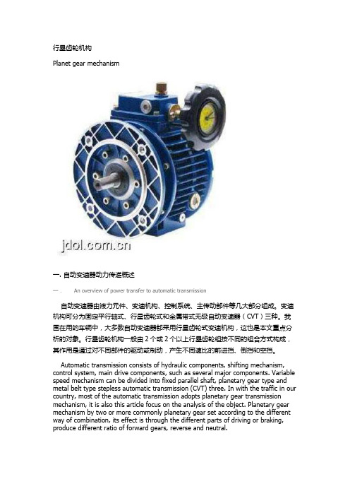
行星齿轮机构Planet gear mechanism一.自动变速器动力传递概述一.An overview of power transfer to automatic transmission自动变速器由液力元件、变速机构、控制系统、主传动部件等几大部分组成。
变速机构可分为固定平行轴式、行星齿轮式和金属带式无级自动变速器(CVT)三种。
我国在用的车辆中,大多数自动变速器都采用行星齿轮式变速机构,这也是本文重点分析的对象。
行星齿轮机构一般由2个或2个以上行星齿轮组按不同的组合方式构成,其作用是通过对不同部件的驱动或制动,产生不同速比的前进挡、倒挡和空挡。
Automatic transmission consists of hydraulic components, shifting mechanism, control system, main drive components, such as several major components. Variable speed mechanism can be divided into fixed parallel shaft, planetary gear type and metal belt type stepless automatic transmission (CVT) three. In with the traffic in our country, most of the automatic transmission adopts planetary gear transmission mechanism, it is also this article focus on the analysis of the object. Planetary gear mechanism by two or more commonly planetary gear set according to the different way of combination, its effect is through the different parts of driving or braking, produce different ratio of forward gears, reverse and neutral.换挡执行元件的作用是约束行星齿轮机构的某些构件,包括固定并使其转速为0,或连接某部件使其按某一规定转速旋转。
机械英语——精选推荐
机械英语阿基⽶得蜗杆straight sided axial worm ZA-worm法向直廓蜗杆straight sided normal worm ZN-worm圆弧圆柱蜗杆arc-contact worm 平⾯蜗轮wildhaber-wormaheel锥蜗杆spiroid锥蜗轮spiroid gear中间平⾯mid-plane分度圆reference circle齿顶圆tip circle齿根圆root circle齿距和升程pitch and lead齿⾼tooth depth齿顶⾼addendum齿根⾼dedendum节圆齿顶⾼working addendum节圆齿根⾼working dedendum⼯作⾼度working dedendum线性参数linear dimensions蜗杆齿宽worm face width蜗轮齿宽face width直径系数diameter quotient 咽喉半径gorge radius顶隙bottom clearance圆周侧隙circumferential backlash法向侧隙normal backlash⾓参数angular dimensions齿宽⾓width angle分度圆导程⾓lead-angle基圆导程⾓base lead angle齿轮副gear pair平⾏轴齿轮副gear pair with parallel axes相交轴齿轮副gear pair with intersecting axles交错轴齿轮副gear pair with non-parallel齿轮系gear train复合⾏星齿轮系compound planetary gear train配对齿轮mating gears⼩齿轮pinion⼤齿轮wheel⾏星齿轮planet gear⾏星架planet carrier太阳轮sun gear内齿圈ring gear外齿轮external gear内齿轮internal gea减速齿轮副speed reducing gear pair增速齿轮副speed increasing gear train中⼼距centre distance轴交⾓shaft angle连⼼线line of centres齿数⽐gear ratio传动⽐transmission ratio 减速⽐speed reducing ratio参考平⾯reference planes轴平⾯axial plane基准平⾯datum plane节平⾯pitch plane端平⾯transverse plane法平⾯normal plane遐想曲⾯imaginary srufaces分度曲⾯reference surface节曲⾯pitch surface 齿顶曲⾯tip surface齿根曲⾯root surface基本齿廓basic rack tooth profile产形齿条counterpart rack基准线datum line轮齿特性teetch characteristics轮齿gear 齿槽tooth space右旋齿right-hand teeth左旋齿left-hand teeth齿⾯tooth flank右侧齿⾯right flank 左侧齿⾯left flank同侧齿⾯corresponding flanks异侧齿⾯opposite flanks⼯作齿⾯working flank⾮⼯作齿⾯non-working flank 相齿齿⾯mating flank可⽤齿⾯rsable flank有效齿⾯active flank上齿⾯addendum flank下齿⾯dedendum flank齿根过渡曲⾯fillet齿顶⾯crest top land齿槽底⾯(槽底)bottom land齿廓tooth profile端⾯齿廓transverse profile法向齿廓normal profile轴向齿廓axial profile齿线tooth trace 齿棱tip surface模数module端⾯模数transverse module法⾯模数normal module轴向模数axial module径节diametral pitch当量齿数virtual number of teeth头数number of threads螺旋线helix and spirals圆锥螺旋线conical spiral螺旋⾓helix angle导程lead 导程⾓lead angle摆线trochoids 外摆线eqicycloid圆⼼渐开线involute to a circle延伸渐开线prolate involute螺旋⾯helicoid⼲涉interference修形correction of the flank shape修像tip relief修根root relief齿⾯修形axial modification齿端修薄end relief⿎形修整crowning挖根undercut瞬时轴instantaneous axis啮合engagement mesh端⾯啮合线transverse path of contact啮合齿⾯surface of action啮合平⾯plane of action重合度contact ratio and overlap ratio总作⽤弧total arc of transmission纵向作⽤弧overlap arc总作⽤⾓total angle of transmission径向变位系数overlap arc圆程齿轮和圆柱齿轮副ckyclindrical gears and gear pairs齿条rack直齿轮spur gear斜齿轮helical gear直齿条spur rack⼤字齿轮double-helical gear渐开线齿轮involute cylindrical gear圆弧圆柱齿轮circular -arc gear分度圆柱⾯reference cylinder节圆柱⾯pitch cylinder基圆柱⾯base cylinder齿顶圆柱⾯tip cylinder齿根圆柱⾯root cylinder节点pitch point分度圆pitch line节圆pitch circle基圆base circle齿顶圆(顶圆)tip circle齿根圆(根圆)root circle法向螺旋线齿距pitch齿距⾓angular pitch公法线总长base tangent length分度圆直径reference diameter齿⾼tooth depth齿宽face width齿顶⾼dedendum齿根⾼dedendum弦齿⾼chordal height固定弦齿⾼constant cord height齿厚tooth thickness惊险电影thriller movie电影院常客cinemogoer以惊险的谋杀疑案为主线thriller nuder mystery at its heart顶隙bottom clearance圆周侧隙circumferential backlash法向侧隙normal backlash径向侧隙radial backlash锥齿轮bevel gear锥齿轮副bevel gear pair准双曲⾯齿轮副hypoid gear pair冠轮crown gear端⾯齿盘contrate gear直齿锥齿轮straight bevel gear斜齿锥齿轮helical bevel gear 曲线齿锥齿轮spiral bevel gear弧齿锥齿轮gleason spiral bevel gear摆线齿锥齿轮overlikon spiral bevel gear零度锥齿轮zerol bevel gear分度圆锥⾯reference cone分度圆reference circle分锥顶点reference cone apex外锥距outer cone distance分度圆直径reference diameter齿⾼tooth depth齿顶⾼addendum 齿根⾼dedendum⼯作⾼度working depth弦齿⾼chordal height齿距pitch 齿厚tooth thickness弦齿厚chordal tooth thickness齿槽宽space width 齿宽face width安装距locating distance轮冠距tip distance冠顶距apex to crown顶隙bottom clearance分度圆锥⾓reference cone angle 齿顶⾓addendum angle 齿根⾓dedendum angle 压⼒⾓pressure angle 齿厚半⾓tooth thickness half angle槽宽半⾓apace width half angle蜗杆worm蜗杆副worm gear pair环⾯蜗杆enveloping worm圆柱蜗杆副cylindrical worm gear渐开线蜗杆involute helicoid worm(ZI-worm)曲折的路winding raod英磅english pounds齿轮Toothed gear;Gear齿轮副Gear pair平⾏轴齿轮副Gear pair with parallel axes相交轴齿轮副Gear pair with intersecting axes齿轮系Train of gears⾏星齿轮系Planetary gear train齿轮传动Gear drive;Gear transmission配对齿轮Mating gears⼩齿轮Pinion⼤齿轮Wheel;Gear主动齿轮Driving gear从动齿轮Driven gear⾏星齿轮Planet gear⾏星架Planet carrier太阳轮Sun gear内齿圈Ring gear;Annulus gear外齿轮External gear内齿轮Internal gear中⼼距Centre distance轴交⾓Shaft angle连⼼线Line of centres减速齿轮副Speed reducing gear pair增速齿轮副Speed increasing gear pair齿数⽐Gear ratio传动⽐Transmissionratio轴平⾯Axial plane基准平⾯Datum plane节平⾯Pitch plane端平⾯Transverse plane法平⾯Normal plane分度曲⾯Reference surface节曲⾯Pitch surface齿顶曲⾯Tip surface齿根曲⾯Root surface基本齿廓Basic tooth profile基本齿条Basic rack 产形齿条Counterpart rack产形齿轮Generating gear of a gear产形齿⾯Generating flank基准线Datum line轮齿Gear teeth;Tooth 齿槽Tooth space右旋齿Right-hand teeth左旋齿Left-hand teeth变位齿轮Gears with addendum modification;X-gears⾼度变位圆柱齿轮副X-gear pair with reference centre distance⾓度变位圆柱齿轮副X-gear pair with modified centre distance⾼度变位锥齿轮副X-gear pair without shaft angle modification⾓度变位圆柱齿轮副X-gear pair with shaft angle modification变位系数Modification coefficient变位量Addendum modification径向变位系数Addendum modification coefficient 中⼼距变位系数Centre distance modification coefficient圆柱齿轮Cylindrical gear顶圆Tip circle根圆Root circle齿距Pitch齿距⾓Angular pitch公法线长度Base tangent length分度圆直径Reference diameter节圆直径Pitch diameter基圆直径Base diameter顶圆直径Tip diameter根圆直径Root diameter齿根圆⾓半径Fillet radius齿⾼Tooth depth⼯作⾼度Working depth齿顶⾼Addendum齿根⾼Dedendum弦齿⾼Chordal height固定弦齿⾼Constant chord height齿宽Facewidth有效齿宽Effective facewidth端⾯齿厚Transverse tooth thickness 法向齿厚Normal tooth thickness端⾯基圆齿厚Transverse base thickness法向基圆齿厚Normal base thickness端⾯弦齿厚Transverse chordal tooth thickness固定弦齿厚Constant chord端⾯齿顶厚Crest width法向齿顶厚Normal crest width端⾯齿槽宽Transverse spacewidth法向齿槽宽Normal spacewidth齿厚半⾓Tooth thickness half angle槽宽半⾓Spacewidth half angle压⼒⾓Pressure angle齿形⾓Nominal pressure angle圆弧圆柱蜗杆Arc-contact worm;hollow flank worm;ZC-worm直廓环⾯蜗杆Enveloping worm with straight line grneratrix;TA worm平⾯蜗杆Planar worm wheel;P-worm wheel平⾯包络环⾯蜗杆Planar double enveloping worm;TP-worm平⾯⼆次包络蜗杆Planar double-enveloping worm wheel;TP-worm wheel锥⾯包络环⾯蜗杆Toroid enveloping worm wheel;TK-worm wheel渐开线包络环⾯蜗杆Toroid enveloping worm hich involute holicoid generatrix;TI-worm锥蜗杆Spiroid锥蜗轮Spiroid gear锥蜗杆副Spiroid gear pair中平⾯Mid-plane长幅内摆线Prolate hypocycloid短幅内摆线Curtate hypocycloid渐开线Involute;Involute to a circle延伸渐开线Prolate involute缩短渐开线Curtate involute球⾯渐开线Spherical involute渐开螺旋⾯Involute helicoid阿基⽶德螺旋⾯Screw helicoid球⾯渐开螺旋⾯Spherical involute helicoid圆环⾯Toroid圆环⾯的母圈Generant of the toroit圆环⾯的中性圈Middle circle of the toroid圆环⾯的中间平⾯Middle-plane of the toroid 圆环⾯的内圈Inner circle of the toroid啮合⼲涉Meshing interference切齿⼲涉Cutter interference齿廓修型Profile modification;Profile correction修缘Tip relief修根Root relief齿向修形Axial modification;Longitudinal correction齿端修薄End relief⿎形修整Crowning⿎形齿Crowned teeth挖根Undercut瞬时轴Instantaneous axis瞬时接触点Point of contact瞬时接触线Line of contact端⾯啮合线Transverse path of contact啮合曲⾯Surface of action啮合平⾯Plane of action啮合区域Zone of action总作⽤弧Total arc of transmission端⾯作⽤弧Transverse arc of transmission纵向作⽤弧Overlap arc总作⽤⾓Total angle of transmission端⾯作⽤⾓Transverse angle of transmission纵向作⽤⾓Overlap angle总重合度Total contact ratio端⾯重合度Transverse ratio纵向重合度Overlap ratio标准齿轮Standard gears⾮变位齿轮X-gero gear标准中⼼距Referencr centre distance名义中⼼距Nominal centre distance分度圆柱⾯Reference cylinder节圆柱⾯Pitch cylinder基圆柱⾯Basic cylinder齿顶圆⾯Tip cylinder齿根圆柱⾯Root cylinder节点Pitch point节线Pitch line分度圆Reference circle节圆Pitch circle基圆Basic circle定位⾯Locating face外锥距Outer cone distance内锥距Inner cone distance中点锥距Mean cone distance背锥距Back cone distance安装距Locating distance轮冠距Tip distance;crown to back冠顶距Apex to crown偏置距Offset齿线偏移量Offset of tooth trace分锥⾓Reference cone angle节锥⾓Pitch cone angle顶锥⾓Tip angle根锥⾓Root angle背锥⾓Back cone angle 齿顶⾓Addendum angel齿根⾓Dedendum angle任意点压⼒⾓Pressure angle at a point任意点螺旋⾓Spiral angle at a point 中点螺旋⾓Mean spiral angle⼤端螺旋⾓Outer spiral angle⼩端螺旋⾓Inner spiral angle蜗杆Worm蜗轮Worm wheel蜗杆副Worm gear pair圆柱蜗杆Cylindrical worm圆柱蜗杆副Cylindrical worm pair环⾯蜗杆Enveloping worm环⾯蜗杆副Enveloping worm pair阿基⽶德蜗杆Straight sided axial worm;ZA-worm渐开线蜗杆Involute helicoid worm;ZI-worm法向直廓蜗杆straight sided normal worm;ZN-worm锥⾯包络圆柱蜗杆Milled helicoid worm;ZK-worm椭圆齿轮Elliptical gear⾮圆齿轮副Non-circular gear pair圆柱针轮副Cylindsical lantern pinion and wheel针轮Cylindsical tan tein gear ;pin-wheel谐波齿轮副Harmoric gear drive波发⽣器Wave generator柔性齿轮Flexspine刚性齿轮Circular spline⾮圆齿轮Non-circular gear分度圆环⾯Reference tosoidscissa 横坐标absolute dimensional factor 绝对尺⼨系数absolute motion 绝对运动absolute velocity 绝对速度acceleration 加速度acceleration analysis 加速度分析acceleration diagram 加速度曲线acme thread form 梯形螺纹actual line of action 实际啮合线addendum 齿顶⾼addendum circle 齿顶圆adjustable speed motors 调速电动机advance-to return-time ratio 急回系数advance-to return-time ratio ⾏程速⽐系数air spring空⽓弹簧allowable amount of unbalance 许⽤不平衡量allowable pressure angle 许⽤压⼒⾓allowable stress; permissible stress 许⽤应⼒amount of unbalance 不平衡量amplitude of vibration 振幅analysis of mechanism 机构分析analytical design 解析设计analytical method 分析法angle of contact 包⾓angular acceleration ⾓加速度angular contact ball bearing ⾓接触球轴承angular contact bearing ⾓接触轴承angular contact radial bearing ⾓接触向⼼轴承angular contact thrust bearing ⾓接触推⼒轴承angular velocity ⾓速度angular velocity ratio ⾓速⽐anneal 退⽕annular spring 环形弹簧anti-friction quality 减摩性aperiodic speed fluctuation ⾮周期性速度波动application factor ⼯况系数applied force 作⽤⼒Archimedes worm 阿基⽶德蜗杆Arctan 反正切arm 臂部assembly condition 装配条件Assur group 杆组atlas 图册、图谱automation ⾃动化average stress 平均应⼒average velocity 平均速度axial contact bearing 轴向接触轴承axial direction 轴向axial internal clearance 轴向游隙axial load 轴向载荷axial load factor 轴向载荷系数axial plane 轴向平⾯axial thrust load 轴向分⼒axial tooth profile 轴向齿廓back angle 背锥⾓back cone distance 背锥距back cone ;normal cone 背锥back-to-back arrangement 背对背安装backlash 侧隙backlash 齿侧间隙backlash 间隙balance 平衡balance of machinery 机械平衡balance of mechanism 机构平衡balance of rotor 转⼦平衡balance of rotors 回转体平衡balance of shaking force 惯性⼒平衡balancing machine 平衡机balancing mass 平衡质量balancing quality 平衡品质balancing speed 平衡转速balata spring 橡胶弹簧ball 球ball bearing 球轴承ball screw 滚珠丝杆band brake 带式制动器barrel (cylindric) cam 圆柱式凸轮步进运动机构base circle 基圆base cone 基圆锥base cylinder 基圆柱base pitch 基圆齿距basic dynamic axial load rating 轴向基本额定动载荷basic dynamic radial load rating 径向基本额定动载荷basic rating life 基本额定寿命basic static axial load rating 轴向基本额定静载荷basic static radial load tating 径向基本额定静载荷beading stress 弯曲应⼒bearing alloy 轴承合⾦bearing block 轴承座bearing bore diameter 轴承内径bearing bush 轴⽡、轴承衬bearing capacity 承载能⼒bearing capacity factor 承载量系数bearing cup 轴承盖bearing height 轴承⾼度bearing life 轴承寿命bearing outside diameter 轴承外径bearing ring 轴承套圈bearing width 轴承宽度belleville spring 碟形弹簧belt driving 带传动belt pulley 带轮bending moment 弯矩bevel gear 锥齿轮bevel gears 圆锥齿轮机构bevel pulley; bevel wheel 锥轮bisector 平分线black box ⿊箱blank 齿轮轮坯blank 轮坯block diagram 框图blower ⿎风机body guidance mechanism 刚体导引机构bold line 粗线bolts 螺栓bottom clearance 顶隙boundary dimension 外形尺⼨brake 制动器buttress thread form 锯齿形螺纹calculated bending moment 计算弯矩cam 凸轮cam , cam mechanism 凸轮机构cam profile 实际廓线cam profile 凸轮廓线cam with oscillating follower 摆动从动件凸轮机构cantilever beam 悬臂梁cantilever structure 悬臂结构Cartesian coordinate manipulator 直⾓坐标操作器cascade speed control 串级调速case-based design,CBD 基于实例设计center distance 中⼼距center distance change 中⼼距变动center of mass 质⼼center of pressure 压⼒中⼼central gear 中⼼轮centrifugal force 离⼼⼒centrifugal force 向⼼⼒centrifugal seal 离⼼密封centrifugal stress 离⼼应⼒chain 链chain dotted line 点划线chain gearing 链传动装置chamfer 倒⾓change gear ; change wheel 变速齿轮characteristics 特性chassis 底座circular gear 圆形齿轮circular pitch 齿距circular pitch; pitch of teeth 节距circular thickness 圆弧齿厚circulating power load 循环功率流clearance 径向间隙clockwise 顺时针closed chain mechanism 闭链机构closed kinematic chain 闭式链clutch 离合器coarse thread 粗⽛螺纹coefficient of friction 摩擦系数coefficient of speed fluctuation 机械运转不均匀系数coefficient of speed fluctuation 速度不均匀( 波动) 系数coefficient of travel speed variation ⾏程速度变化系数coefficient of velocity fluctuation 运转不均匀系数coincident points 重合点combination in parallel 并联式组合combination in series 串联式组合combined efficiency; overall efficiency 总效率combined mechanism 组合机构combined stress 复合应⼒common apex of cone 锥顶common normal line 公法线compensation 补偿complex mechanism 复杂机构composite tooth form 组合齿形compound (or combined) gear train 复合轮系compound combining 复合式组合compound flat belt 复合平带compound gear train 混合轮系compound hinge 复合铰链Compound screw mechanism 复式螺旋机构compression strength 抗压强度compressive stress 压应⼒compressor 压缩机computer aided design, CAD 计算机辅助设计computer aided manufacturing, CAM 计算机辅助制造computer integrated manufacturing system, CIMS 计算机集成制造系统concavity 凹⾯、凹度concept design, CD ⽅案设计、概念设计concurred design, CD 并⾏设计concurrent engineering 并⾏⼯程condition of self-locking ⾃锁条件conduction of heat 导热性cone angle 圆锥⾓cone distance 锥距conjugate cam 共轭凸轮conjugate profiles 共轭齿廓conjugate yoke radial cam 等径凸轮connecting rod, coupler 连杆conoid helical-coil compression spring 圆锥螺旋扭转弹簧constant-breadth cam 等宽凸轮constant-velocity (or double) universal joint 双万向联轴节constitution of mechanism 机构组成constraining force 约束反⼒constraint 约束constraint condition 约束条件consumption 消耗contact points 啮合点contact ratio 重合度contact seal 接触式密封contact stress 接触应⼒conventional mechanism; mechanism in common use 常⽤机构convex 凸的,凸⾯体convex roller 球⾯滚⼦coordinate frame坐标系correcting plane 平衡平⾯correcting plane 校正平⾯corrosion resistance 耐腐蚀性cosine acceleration (or simple harmonic) motion 余弦加速度运动counterclockwise (or anticlockwise) 逆时针counterweight 平衡重couple ⼒偶coupler-curve 连杆曲线coupling ; shaft coupling 联轴器crank 曲柄crank angle between extreme (or limiting) positions 极位夹⾓crank arm, planet carrier 系杆crank shaft 曲轴crank shaper (guide-bar) mechanism 曲柄导杆机构crank-rocker mechanism 曲柄摇杆机构creation design 创新设计critical speed 临界转速cross-belt drive 交叉带传动crossed helical gears 交错轴斜齿轮crown gear 冠轮curvature 曲率curve matching 曲线拼接curved-shoe follower 曲⾯从动件curvilinear motion 曲线运动cutter ⼑具cycle of motion 运动周期cycloidal gear 摆线齿轮cycloidal motion 摆线运动规律cycloidal tooth profile 摆线齿形cycloidal-pin wheel 摆线针轮cylindric pair 圆柱副cylindrical cam 圆柱凸轮cylindrical coordinate manipulator 圆柱坐标操作器cylindrical roller 圆柱滚⼦cylindrical roller bearing 圆柱滚⼦轴承cylindrical worm 圆柱蜗杆cylindroid helical-coil compression spring 圆柱螺旋压缩弹簧cylindroid helical-coil extension spring 圆柱螺旋拉伸弹簧cylindroid helical-coil torsion spring 圆柱螺旋扭转弹簧dedendum 齿根⾼dedendum circle 齿根圆deep groove ball bearing 深沟球轴承deformation 变形degree of freedom, mobility ⾃由度degree of reliability 可靠度denominator 分母depth of cut 切齿深度derivative 导数design constraints 设计约束design for product`s life cycle, DPLC ⾯向产品⽣命周期设计design methodology 设计⽅法学design variable 设计变量detrimental resistance 有害阻⼒diameter series 直径系列diametral pitch 径节diametral quotient 蜗杆直径系数diametral quotient 直径系数differential 差速器differential gear train 差动轮系differential screw mechanism 差动螺旋机构differential screw mechanism 微动螺旋机构dimension series 尺⼨系列direct (forward) kinematics 正向运动学disc brake 圆盘制动器disc friction clutch 圆盘摩擦离合器disk cam 盘形凸轮disk-like rotor 盘形转⼦displacement 位移displacement diagram 位移曲线double crank mechanism 双曲柄机构double Haas planer 龙门刨床double rocker mechanism 双摇杆机构double roller chain coupling 滚⼦链联轴器double row bearing 双列轴承double slider coupling; Oldham‘s coupling ⼗字滑块联轴器double-direction thrust bearing 双向推⼒轴承double-slider mechanism, ellipsograph 双滑块机构driven gear 从动轮driven link, follower 从动件driven pulley 从动带轮driven system 传动系统driving force 驱动⼒driving gear 主动齿轮driving link 原动件driving link 主动件driving moment (torque) 驱动⼒矩driving pulley 主动带轮dwell 停歇dyad II级杆组dynamic analysis design 动态分析设计dynamic analysis of machinery 机械动⼒分析dynamic balance 动平衡dynamic balancing machine 动平衡机dynamic characteristics 动态特性dynamic design of machinery 机械动⼒设计dynamic energy 动能dynamic equivalent axial load 轴向当量动载荷dynamic equivalent radial load 径向当量动载荷dynamic load 动载荷dynamic lubrication 动⼒润滑dynamic reaction 动压⼒dynamic viscosity 动⼒粘度dynamically equivalent model 等效动⼒学模型dynamics 动⼒学dynamics of machinery 机械动⼒学eccentric 偏⼼盘eccentric mass 偏⼼质量eccentricity ratio 偏⼼率effective circle force 有效圆周⼒effective resistance ⼯作阻⼒effective resistance moment ⼯作阻⼒矩effective tension 有效拉⼒elastic coupling ; flexible coupling 弹性联轴器elasticity sliding motion 弹性滑动end-effector 末端执⾏器energy 能量engagement, mesh, gearing 啮合engaging-in 啮⼊engaging-out 啮出epicyclic gear train 周转轮系equilibrium ⼒平衡equivalent 等效量equivalent coefficient of friction 当量摩擦系数equivalent force 等效⼒equivalent link 等效构件equivalent load 当量载荷equivalent mass 等效质量equivalent mechanism 替代机构equivalent moment of force 等效⼒矩equivalent moment of inertia 等效转动惯量equivalent spur gear of the bevel gear 锥齿轮的当量直齿轮equivalent spur gear of the helical gear 斜齿轮的当量直齿轮equivalent spur gear; virtualgear 当量齿轮equivalent teeth number; virtual number of teeth 当量齿数evaluation and decision 评价与决策executive link; working link 执⾏构件external force 外⼒external gear 外齿轮external loads ⼯作载荷extreme (or limiting) position 极限位置face width 平底宽度face-to-face arrangement ⾯对⾯安装factor of stress concentration 应⼒集中系数factored moment; calculation moment 计算⼒矩fastener 紧固件fatigue limit 疲劳极限fatigue strength 疲劳强度feather key 滑键、导键feedback combining 反馈式组合felt ring seal 毡圈密封ferrofluid seal 铁磁流体密封field balancing 现场平衡fillet radius 圆⾓半径final contact, end of contact 终⽌啮合点fine threads 细⽛螺纹fixed link; frame 固定构件flange coupling 凸缘联轴器flat belt 平带flat belt driving 平带传动flat leaf spring 板簧flat-face follower 平底从动件flexible automation 柔性⾃动化flexible impulse; soft shock 柔性冲击flexible manufacturing system; FMS 柔性制造系统flexible rotor 挠性转⼦flexspline 柔轮fluctuating circulating stress 脉动循环应⼒fluctuating load 脉动载荷flywheel 飞轮follower dwell 从动件停歇follower motion 从动件运动规律force ⼒force polygon ⼒多边形force-drive (or force-closed) cam mechanism ⼒封闭型凸轮机构forced vibration 强迫振动forge 锻造form cutting 仿形法form factor 齿形系数four-bar linkage 四杆机构frame, fixed link 机架freezing point; solidifying point 凝固点frequency 频率frequency control of motor speed 变频调速frequency converters 变频器frequency of vibration 振动频率friction 摩擦friction angle 摩擦⾓friction circle 摩擦圆friction force 摩擦⼒friction moment 摩擦⼒矩frictional resistance 摩擦阻⼒full balance of shaking force 惯性⼒完全平衡function analyses design 功能分析设计function generation 函数⽣成function generator 函数发⽣器fundamental mechanism 基础机构fuzzy evaluation 模糊评价fuzzy set 模糊集gas bearing ⽓体轴承gasket 垫圈gasket seal 垫⽚密封gear 齿轮gear 齿轮机构gear coupling 齿轮联轴器gear ratio 齿数⽐gear shaper 插齿机gear train 轮系gear wheel ⼤齿轮gearing; transmission gear 传动装置general constraint 公共约束generalized coordinate ⼴义坐标generalized kinematic chain ⼀般化运动链generating 展成法generating cutting 范成法generating line 发⽣线generating line of involute 渐开线发⽣线generating plane 发⽣⾯generation mechanism ⼴义机构Geneva mechanism ;Maltese cross 槽轮机构Geneva numerate 槽数Geneva wheel 槽轮Geneva wheel ; Geneva gear 马⽿他机构graphical method 图解法Grashoff`s law 格拉晓夫定理Grashoff`s law 曲柄存在条件green design ; design for environment 绿⾊设计grey cast iron 灰铸铁grinding wheel groove 砂轮越程槽groove cam 槽凸轮gyroscope 陀螺仪H. Hertz equation 赫兹公式hands of worm 蜗杆旋向harmonic driving 谐波传动harmonic gear 谐波齿轮harmonic generator 谐波发⽣器heat balance; thermal equilibrium 热平衡height series ⾼度系列helical bevel gear 螺旋锥齿轮helical gear 斜齿圆柱齿轮helical pair 螺旋副helical torsion spring 扭簧helix ,helical line 螺旋线helix angle 螺旋⾓helix angle at reference cylinder 分度圆柱螺旋⾓herringbone gear ⼈字齿轮high speed belt ⾼速带higher pair ⾼副hindley worm 直廓环⾯蜗杆hinge 铰链、枢纽hob 滚⼑hob ,hobbing cutter 齿轮滚⼑hollow flank worm 圆弧圆柱蜗杆Hooks coupling ; universal coupling 万向联轴器hour-glass 砂漏hydraulic couplers 液⼒耦合器hydraulic mechanism 液压机构hydraulic stepless speed changes 液压⽆级变速hydrodynamic drive 液⼒传动hyperboloid gear 双曲⾯齿轮hypoid gear 准双曲⾯齿轮idle gear 惰轮imbalance (or unbalance) 不平衡in-line slider-crank (or crank-slider) mechanism 对⼼曲柄滑块机构increment or decrement work 盈亏功inertia force 惯性⼒infinite ⽆穷⼤initial contact , beginning of contact 起始啮合点inner ring 内圈innovation ; creation 创新input link 输⼊构件instantaneous center 瞬⼼instantaneous center of velocity 速度瞬⼼integrate 积分intelligent design, ID 智能化设计interchangeable gears 互换性齿轮interference ⼲涉intermittent gearing 不完全齿轮机构intermittent motion mechanism 间歇运动机构internal force 内⼒internal gear 内齿轮inverse ( or backward) kinematics 反向运动学inverse cam mechanism 凸轮倒置机构involute 渐开线involute equation 渐开线⽅程involute function 渐开线函数involute gear 渐开线齿轮involute helicoid 渐开螺旋⾯involute profile 渐开线齿廓involute spline 渐开线花键involute worm 渐开线蜗杆jack 千⽄顶Jacobi matrix 雅可⽐矩阵jaw (teeth) positive-contact coupling ⽛嵌式联轴器jerk 跃度jerk diagram 跃度曲线jointed manipulator 关节型操作器journal 轴颈kenematic viscosity 运动粘度Kennedy`s theorem 三⼼定理key 键keyway 键槽kinematic analysis 运动分析kinematic chain 运动链kinematic design 运动设计kinematic design ofmechanism 机构运动设kinematic inversion 反转法kinematic inversion 机架变换kinematic inversion 运动倒置kinematic pair 运动副kinematic precept design 运动⽅案设计kinematic sketch 运动简图kinematic sketch of mechanism 机构运动简图kinematic synthesis 运动综合kinematical seal 动密封knife-edge follower 尖底从动件labyrinth seal 迷宫密封lathe 车床layout of cam profile 凸轮廓线绘制lead 导程lead 螺纹导程lead angle 导程⾓lead angle at reference cylinder 分度圆柱导程⾓leakage 泄漏length of line of action 啮合线长度lift 升距line of action 啮合线line of centers 连⼼线linear motion 直线运动link 构件linkage 连杆机构lip rubber seal 唇形橡胶密封liquid spring 液体弹簧load 载荷load balancing mechanism 均衡装置load rating 额定载荷load—deformation curve 载荷—变形曲线load—deformation diagram 载荷—变形图loom 织布机lower pair 低副lubricant 润滑剂lubricant film 润滑油膜lubrication 润滑lubrication device 润滑装置machine design; mechanical design 机械设计machinery 机械magnetic fluid bearing 磁流体轴承Maltese cross 马⽿他⼗字manipulator 机器⼈操作器manipulator 机械⼿mass 质量mass-radius product 质径积matching 拼接mathematic model 数学模型matrix 矩阵maximum difference work between plus and minus work 最⼤盈亏功mean diameter 中径mean screw diameter 平均中径mechanical advantage 机械利益mechanical behavior 机械特性mechanical creation design, MCD 机械创新设计mechanical efficiency 机械效率mechanical speed governors机械调速mechanical stepless speed changes 机械⽆级变速mechanical system 机械系统mechanical system design, MSD 机械系统设计mechanical-electrical integration system design机电⼀体化系统设计mechanism 机构mechanism 机构学mechanism with flexible elements 挠性机构membership ⾪属度metric gears 公制齿轮mid-plane 中间平⾯milled helicoids worm 锥⾯包络圆柱蜗杆minimum radius 最⼩向径minimum teeth number 最少齿数minor diameter ⼩径modern machine design 机械的现代设计modification coefficient 变位系数modified gear 变位齿轮modified sine acceleration motion 修正正弦加速度运动规律modified trapezoidal acceleration motion 修正梯形加速度运动规律modular design, MD 模块化设计modular system 模块式传动系统modulation, regulation 调节module 模数moment ⼒矩moment of couple ⼒偶矩moment of flywheel 飞轮矩moment of inertia ,shaking moment 惯性⼒矩moment of torque 扭矩morphology box 模幅箱movinglink 运动构件multi-diameter shaft 阶梯轴multi-row bearing 多列轴承narrow V belt 窄V带needle roller 滚针needle roller bearing 滚针轴承nominal diameter 公称直径nominal stress 名义应⼒、公称应⼒Nomogram 诺模图non-circular gear ⾮圆齿轮non-contact seal ⾮接触式密封nonstandard gear ⾮标准齿轮normal circular pitch 法⾯齿距normal force 法向⼒normal load 垂直载荷、法向载荷normal module 法⾯模数normal parameters 法⾯参数normal pitch 法向齿距normal plane 法⾯normal pressure angle 法⾯压⼒⾓normal stress 正应⼒、法向应⼒normal tooth profile 法向齿廓number of threads 蜗杆头数number of waves 波数numerator 分⼦objective function ⽬标函数offset 偏置式offset circle 偏距圆offset distance 偏( ⼼) 距offset knife-edge follower 偏置尖底从动件offset roller follower 偏置滚⼦从动件offset slider-crank mechanism 偏置曲柄滑块机构oil bearing 含油轴承oil bottle 油杯oil can 油壶oil consumption 耗油量oil consumption factor 耗油量系数oily ditch seal 油沟密封Oldham coupling 双转块机构on-net design, OND ⽹上设计open chain mechanism 开链机构open kinematic chain 开式链open-belt drive 开⼝传动operation control device 操纵及控制装置operation mechanism ⼯作机构optimal design 优化设计ordinary gear train; gear train with fixed axes 定轴轮系ordinate 纵坐标original mechanism 原始机构oscillating bar 摆杆oscillating follower 摆动从动件oscillating guide-bar mechanism 摆动导杆机构other mechanism in common use 其他常⽤机构outer ring 外圈output link 输出构件output mechanism 输出机构output shaft 输出轴output torque 输出⼒矩output work 输出功overlap contact ratio 纵向重合度packer 打包机paired mounting 成对安装parabolic motion 抛物线运动parabolic motion; constant acceleration and deceleration motion 等加等减速运动规律parallel combined mechanism 并联组合机构parallel helical gears 平⾯轴斜齿轮parallel key 普通平键parallel mechanism 并联机构parameterization design, PD 参数化设计partial balance of shaking force 惯性⼒部分平衡passive degree of freedom 局部⾃由度path generation 轨迹⽣成path generator 轨迹发⽣器pawl 棘⽖pedal 踏板periodic speed fluctuation 周期性速度波动phase angle of unbalance 不平衡相位pin 销pinion ⼩齿轮pinion and rack 齿轮齿条机构pinion cutter; pinion-shaped shaper cutter 齿轮插⼑pinion unit 齿轮传动系pitch 周节pitch circle 节圆pitch cone 节圆锥pitch cone angle 节圆锥⾓pitch curve 理论廓线pitch curve 凸轮理论廓线pitch diameter 节圆直径pitch line 节线pitch point 节点pitting (疲劳)点蚀planar cam 平⾯凸轮planar cam mechanism 平⾯凸轮机构planar kinematic pair 平⾯运动副planar linkage 平⾯连杆机构planar mechanism 平⾯机构planar pair, flat pair 平⾯副planet gear ⾏星轮planetary differential 封闭差动轮系planetary drive with small teeth difference 少齿差⾏星传动planetary gear train ⾏星轮系planetary speed changing devices ⾏星轮变速装置planetary transmission ⾏星齿轮装置plasticine 橡⽪泥pneumatic mechanism ⽓动机构pointing; cusp 尖点polar coordinate manipulator 球坐标操作器poly V-belt 多楔带polynomial motion 多项式运动规律pose , position and orientation 位姿positive-drive (or form-closed) cam mechanism 形封闭凸轮机构potted component 密封元件powder metallurgy 粉末合⾦power 功率power screw 螺旋传动power spring 涡圈形盘簧preload 预紧⼒pressure 压⼒pressure angle 压⼒⾓pressure angle of base circle 基圆压⼒⾓pressure angle of involute 渐开线压⼒⾓prime mover 原动机primer mover 原动机prismatic joint 移动关节prismatic pair, sliding pair 移动副productive resistance ⽣产阻⼒pulsating stepless speed changes 脉动⽆级变punch 冲床quadrant 象限quick-return mechanism 急回机构quick-return motion 急回运动raceway 滚道rack 齿条rack cutter; rack-shaped shaper cutter 齿条插⼑rack gear 齿条传动radial (or in-line ) roller follower 对⼼滚⼦从动件radial (or in-line ) translating follower 对⼼直动从动件radial bearing 向⼼轴承radial contact bearing 径向接触轴承radial direction 径向radial internal clearance 径向游隙radial load 径向载荷radial load factor 径向载荷系数radial plane径向平⾯radial reciprocating follower 对⼼移动从动件radius of base circle 基圆半径radius of curvature 曲率半径radius of roller 滚⼦半径ratchet 棘轮ratchet mechanism 棘轮机构rating life 额定寿命reciprocating follower 移动从动件reciprocating motion 往复移动reciprocating seal 往复式密封reduction gear 减速齿轮、减速装置reduction ratio 减速⽐redundant (or passive) constraint 虚约束redundant degree of freedom 冗余⾃由度reference circle; standard (cutting) pitch circle 分度圆reference cone; standard pitch cone 分度圆锥reference line; standard pitch line 分度线regulator, governor 调速器relative gap 相对间隙relative motion 相对运动relative velocity 相对速度reliability 可靠性reliability design, RD 可靠性设计repeated fluctuating load 交变载荷repeated stress 交变应⼒residual stress 残余应⼒resistance 阻抗⼒resultant bending moment 合成弯矩resultant force 合⼒resultant force 总反⼒resultant moment of force 合⼒矩resultant moment of inertia 惯性主矩resultant vector of inertia 惯性主失return 回程revolute (turning) pair 转动副revolute joint 转动关节revolving shaft 转轴Reynolds‘s equation 雷诺⽅程right triangle 直⾓三⾓形rigid bearing 刚性轴承rigid circular spline 刚轮rigid coupling 刚性联轴器rigid impulse (shock) 刚性冲击rigid rotor 刚性转⼦ring gear 内齿圈rise 升程rise 推程rivet 铆钉robot 机器⼈robotics 机器⼈学robust design 稳健设计rocker 摇杆roller 滚⼦roller bearing 滚⼦轴承roller chain 滚⼦链roller clutch 滚柱式单向超越离合器roller follower 滚⼦从动件rolling bearing 滚动轴承rollingbearing identification code 滚动轴承代号rolling element 滚动体rotary motion 旋转运动rotating seal 旋转式密封rotor 转⼦rotor with several masses 多质量转⼦round belt 圆带round belt drive 圆带传动rubber-cushioned sleeve bearing coupling 弹性套柱销联轴器running torque 旋转⼒矩safety factor; factor of safety 安全系数scale ⽐例尺scoring 胶合screw 螺杆screw efficiency 螺纹效率screw mechanism 螺旋机构screw nut 螺母screws 螺钉seal 密封seal belt 密封带seal gum 密封胶sealing arrangement 密封装置section 截⾯self-aligning ball bearing 调⼼球轴承self-aligning bearing 调⼼轴承self-aligning roller bearing 调⼼滚⼦轴承self-locking ⾃锁series combined mechanism 串联式组合机构serration spline 三⾓形花键shaft 轴shaft angle 轴⾓shaft collar 轴环shaft end ring 轴端挡圈shaft shoulder 轴肩shaking couple 振动⼒矩shaper ⽜头刨床shockproof device 防振装置shocks; shock-absorber 缓冲装置silent chain 齿形链、⽆声链simple harmonic motion 简谐运动sine generator, scotch yoke 正弦机构single row bearing 单列轴承single universal joint 单万向联轴节single-direction thrust bearing 单向推⼒轴承singular position 奇异位置six-bar linkage 六杆机构slack-side 松边sleeve 套筒slider 滑块slider-crank (or crank-slider) mechanism 曲柄滑块机构sliding bearing 滑动轴承sliding ratio 滑动率slipping 打滑solid lubricant 固体润滑剂spacewidth 齿槽宽spatial cam 空间凸轮机构spatial kinematic chain 空间运动链spatial kinematic pair 空间运动副spatial linkage 空间连杆机构spatial mechanism 空间机构special kinematic chain 特殊运动链specific heat capacity ⽐热容speed。
《机械设计基础》常用单词中英文对照
《机械设计基础》常用单词中英文对照- common words in Basis of Mechanical Designing一画1.V带V belt2.力force3.力矩moment4.工作载荷serving load5.干摩擦dry friction6.飞轮flier, flywheel7.内圈inner ring8切向键tangential key9.切应力tangential stress10.切削cutting11.双头螺柱stud12.尺寸dimension13.尺寸公差dimensional tolerance14.计算载荷calculating load15.主动轴drive shaft16.凸轮cam17.加工working18.半圆键half round key19.外圈outer ring.20.失效failure21.尼龙nylon22.平键flat key23.打滑slippage24.正火normalizing treatment25.正应力normal stress26.优化设计optimum design27.冲压punching28.动平衡dynamic balance29动载荷moving load30.压力pressure31.压应力compressive stress32压强pressure intensity33.压缩compress34.压缩应力compressive stress35.合金钢alloy steel36.向心轴承centripetal stress37.向心推力轴承centripetal thrust bearing38.导向键guide key39.导轨guide track40当量动载荷equivalent dynamic load41.曲柄 crank42.曲轴crank axle43.曲率半径curvature radius44.有色金属non ferrous metal45.机构mechanism46.机架framework47.机座machine base48.机械machine49.机械加工mechanical working50.机械零件machine element51.机器machine52.灰铸铁gray cast iron53.自锁self locking54.行星轮系planetary gear train55.许用应力allowable stress56.防松locking57.刨削planning58.寿命life59.应力stress60.应力集中stress concentration61.应变strain62.扭转torsion63扭转角angle of torsion64.抗压强度compression strength65抗拉强度tensile strength66.抗弯强度bending strength67.材料material68.极限应力limit stress69.极惯性矩polar moment of inertial70.花键spline71.连杆connecting rod72.周转轮系epicyclic gear train73.屈服强度yield strength74.底板base plate75.底座underframe76.径向力radial force77.径向当量动载荷radial equivalent dynamic load78.径向轴承journal bearing79.径向基本额定动载荷radial elementary rated life80.性能performance81.承载量load carrying capacity82.拉力pulling force83.拉伸tension84.拉伸应力tensile stress85.油膜oil film86.泊松比Poisson’s ratio87.直径diameter88.空心轴hollow axle89.空气轴承air bearing90表面处理surface treatment91.表面淬火surface quenching92转矩torque93.金属材料metallic material94.青铜合金bronze alloy95.非金属材料non metallic material96.齿轮gear97.齿轮模数module of gear teeth98.齿数tooth number99.保持架holding frame100.变应力dynamic stress101.变形deflection, deformation102.变载荷dynamic load103.轮系gear train104.垫片shim105.垫圈washer106.复合材料composite material107.带传动belt driving108.弯曲bend109.弯曲应力bending stress110.弯曲强度bending strength111.弯矩bending moment112.挡圈retaining ring113.残余应力residual stress114.残余变形residual deformation115.点蚀pitting116.相对运动relative motion117.相对滑动relative sliding118.相对滚动relative rolling motion119.矩形花键square key120.结构structure121.结构设计structural design121.结构钢structural steel122.耐磨性wearing quality123.脉动循环应力repeated stress124.轴shaft125.轴瓦bushing126.轴向力axial force127.轴向当量动载荷axial equivalent dynamic load 128.轴向基本额定动载荷axial elementary rated life129.轴承bearing130.轴承合金bearing metal131.轴承油沟grooves in bearing132.轴承衬bearing bush133.轴承座bearing block134.轴承盖bearing cap135.轴环axle ring136.轴肩shaft neck137.轴套shaft sleeve138.退刀槽tool escape139.钢材steel140.钩头楔键gib head key150.钩头螺栓gib head bolt151.挺杆tappet, tapper152.圆柱销cylindrical pin153.圆锥销cone pin154.圆螺母circular nut155.流体动力润滑hydrodynamic lubrication 156.流体静力润滑hydrostatic lubrication 157.润滑lubrication158.润滑油膜lubricant film159.热处理heat treatment160.热平衡heat balance161.疲劳fatigue162.疲劳失效fatigue failure163.疲劳寿命fatigue Life164.疲劳强度fatigue strength165.疲劳裂纹fatigue cracking166.离合器clutch167.紧定螺钉tightening screw168.胶合seizing of teeth169.能量energy170.脆性材料brittle material171.调质钢quenched and tempered steel 172.载荷load173.载荷谱load spectrum174.通用零件universal element175.速度velocity176.部件parts177.铆接riveting178.陶瓷ceramics179.预紧pretighten180.高速传动轴high speed drive shaft181.偏心载荷eccentric load182.偏转角deflection angle183.减速器reductor184.剪切应力shearing stress185.剪切应力shear stress186.基本额定动载荷elementary rated dynamic load 187.基本额定寿命elementary rated life188.密封seal189.密度density190.弹性变形elastic deformation191.弹性流体动力润滑elastohydrodynamic lubrication 192.弹性啮合elastic engagement193.弹性滑动elastic slippage194.弹性模量modulus of elasticity195.弹簧spring196.弹簧垫圈spring washer197.惯性力inertial force198.惯性矩moment of inertia199.接触应力contact stress200.接触角Contact Angle201.推力轴承thrust bearing202.断裂break203.液压hydraulic pressure204.混合润滑mixed lubrication205.渐开线花键involute spline206.焊接welding207.球形阀globe valve208.球墨铸铁nodular cast iron209.粗糙度roughness210.铜合金copper alloy211.铝合金aluminum alloy212.铰链hinge213.黄铜brass214.剩余预紧力residual initial tightening load215.喷丸sand blast216.强度strength217.强度极限ultimate strength218.最小油膜厚度minimum film thickness219.棘轮传动ratchet wheel220.滑动轴承sliding bearing221.滑块slide block222.滑键slide key223硬度hardness224.联轴器coupling225.装配assembly226.铸件casting227.铸钢cast steel228.铸造cast229.铸铁cast iron230.铸铝cast aluminum231.链chain232.链轮chain wheel233.销pin234.销钉联接pin connection235.塑性材料ductile material236.塑性变形plastic deformation 237.塑料plastics238.摇杆rocker239.楔键wedge key240.滚动体Rolling Body241.滚动轴承rolling bearing242.滚压rolling243.滚珠丝杆ball leading screw 244.锡青铜tin bronze245.锥形阀cone valve246.键key247.键槽keyways248.碳化carbonization249.碳素钢carbon steel250.稳定性stability251.腐蚀corrosion252.锻件forged piece253.锻钢forged steel254.锻造forging255.静压轴承hydrostatic bearing 256.静应力steady stress257.静载荷/应力static load/stress 258.摩擦friction259.摩擦力friction force260.摩擦功friction work261.摩擦系数friction coefficient 262.摩擦角friction angle263.摩擦学tribology264.槽轮sheave wheel265.橡胶rubber266.箱体box267.磨削grinding268.磨损wear269.磨损过程wear process270.螺母nut271.螺纹screw272.螺纹threads273.螺纹联接threaded and coupled 274.螺钉pitch275.螺栓bolt276.螺栓联接bolting277.螺旋传动screw-driven机械设计名词术语中英对照机械设计名词术语中英文对照表Chinese English阿基米德蜗杆Archimedes worm安全系数safety factor; factor of safety安全载荷safe load凹面、凹度concavity扳手wrench板簧flat leaf spring半圆键woodruff key变形deformation摆杆oscillating bar摆动从动件oscillating follower摆动从动件凸轮机构cam with oscillating follower 摆动导杆机构oscillating guide-bar mechanism摆线齿轮cycloidal gear摆线齿形cycloidal tooth profile摆线运动规律cycloidal motion摆线针轮cycloidal-pin wheel包角angle of contact保持架cage背对背安装back-to-back arrangement背锥back cone ;normal cone背锥角back angle背锥距back cone distance比例尺scale比热容specific heat capacity闭式链closed kinematic chain闭链机构closed chain mechanism臂部arm变频器frequency converters变频调速frequency control of motor speed变速speed change变速齿轮change gear ; change wheel变位齿轮modified gear变位系数modification coefficient标准齿轮standard gear标准直齿轮standard spur gear表面质量系数superficial mass factor表面传热系数surface coefficient of heat transfer 表面粗糙度surface roughness并联式组合combination in parallel并联机构parallel mechanism并联组合机构parallel combined mechanism并行工程concurrent engineering并行设计concurred design, CD不平衡相位phase angle of unbalance不平衡imbalance (or unbalance)不平衡量amount of unbalance不完全齿轮机构intermittent gearing波发生器wave generator波数number of waves补偿compensation参数化设计parameterization design, PD残余应力residual stress操纵及控制装置operation control device槽轮Geneva wheel槽轮机构Geneva mechanism ;Maltese cross 槽数Geneva numerate槽凸轮groove cam侧隙backlash差动轮系differential gear train差动螺旋机构differential screw mechanism差速器differential常用机构conventional mechanism; mechanism in common use车床lathe承载量系数bearing capacity factor承载能力bearing capacity成对安装paired mounting尺寸系列dimension series齿槽tooth space齿槽宽spacewidth齿侧间隙backlash齿顶高addendum齿顶圆addendum circle齿根高dedendum《机械设计基础》常用单词中英文对照寿命life应力stress应力集中stress concentration应变strain扭转torsion扭转角angle of torsion抗压强度compression strength抗拉强度tensile strength抗弯强度bending strength材料material极限应力limit stress极惯性矩polar moment of inertial花键spline连杆connecting rod周转轮系epicyclic gear train屈服强度yield strength底板base plate底座underframe径向力radial force径向当量动载荷radial equivalent dynamic load 径向轴承journal bearing径向基本额定动载荷radial elementary rated life 性能performance承载量load carrying capacity拉力pulling force拉伸tension拉伸应力tensile stress油膜oil film泊松比Poisson’s ratio直径diameter空心轴hollow axle空气轴承air bearing表面处理surface treatment表面淬火surface quenching转矩torque金属材料metallic material青铜合金bronze alloy非金属材料non metallic material齿轮gear齿轮模数module of gear teeth齿数tooth number保持架holding frame变应力dynamic stress变形deflection, deformation变载荷dynamic load。
- 1、下载文档前请自行甄别文档内容的完整性,平台不提供额外的编辑、内容补充、找答案等附加服务。
- 2、"仅部分预览"的文档,不可在线预览部分如存在完整性等问题,可反馈申请退款(可完整预览的文档不适用该条件!)。
- 3、如文档侵犯您的权益,请联系客服反馈,我们会尽快为您处理(人工客服工作时间:9:00-18:30)。
附录附录1英文原文NATURAL FREQUENCY VEERING INPLANETARY GEARSABSTRACTTo achieve noise and vibration reduction in planetary gear applications, key design parameters are often varied to avoid resonances,optimize load distribution, and reduce weight. In the plots of natural frequencies versus planetary gear parameters,veering phenomena occur when two eigenvalue loci approach each other, but then abruptly veer away. The importance of veering is manifested in the dramatic changes in the vibration modes of the veering natural frequencies and the consequent impact on response.This work analytically characterizes the rules of eigenvalue veering in planetary gears.The coupling factors between two close eigenvalue loci are approximated by perturbation analysis. Special veering patterns were obtained using the unique properties of planetary gear vibration modes.The results are illustrated by an example. Key design parameters were investigated, and generalized guidance is provided for tuning planetary gear natural frequencies.I. INTRODUCTIONNoise and vibration reduction are critical concerns in planetary gear applications. During the design process, system parameters are varied to evaluate alternative design choices,avoid resonances,optimize load distribution,and reduce weight. It is important to characterize the effects of parameter variations on the natural frequencies and vibration modes for effective vibration tuning. In planetary gear dynamic models (Fig. 1), the key design parameters include the mesh stiffnesses, support/bearing stiffnesses, component masses, and moments of inertia. Some plots of natural frequencies versus planetary gear parameters are presented by Cunliffe et al.[1], Botman [2], Kahraman [3,4], and Saada and Velex [5].Natural frequency plots in these studies, especially Ref. 3, show naturalfrequency veering phenomena when two eigenvalue loci approach each other as a parameter is varied, but then abruptly veer away like two similar charges repelling (point B in Fig. 2a). The vibration modes of the veering eigenvalues are strongly coupled and undergo dramatic changes in the veering neighborhood.The phenomenon has been studied extensively [6–9], but it has not been explored in planetary gears.Eigenvalue veering is also related to mode localization that can occur when disorder is introduced into nominally symmetric systems like turbine blades, space antennae, multispan beams, and other structures [6]. In the case of especially sharp veering, it is sometimes difficult to distinguish between intersection and veering just by observing eigenvalue plots.Curve veering/crossing complexity obstructs the tracing of eigenvalue loci under parameter changes. Also, when multiple curves veer or intersect close together (Fig. 3), strong modal coupling and the associated operating condition response changes that occur are not identifiable from frequency loci plots.The objectives of this work were twofold. The first was to analytically derive simple rules that predict eigenvalue veering in planetary gears. The second was to use the veering results, along with previously developed modal properties and eigensensitivity analysis, to define more fully the influence of model parameters on free vibration and to give guidance for tuning natural frequencies.Lin and Parker [10,11] analytically characterized the unique, highly structured properties of planetary gear natural frequency spectra and vibration modes. They also provided simple, closed-form expressions for the sensitivities of natural frequencies and vibration modes to design parameters [12]. These analytical results provide the necessary foundation for the present study of veering rules in planetary gears. The veering rules yield concrete conclusions expressed in simple forms for when two approachingeigenvalues veer or cross. The importance of the veering rules is to identify thoseranges in which small changes in design parameters can dramatically change the vibration modes and consequently the response. The results are illustrated on a benchmark planetary gear(the model parameters and natural frequencies are given in Tables 1 and 2,respectively) used in a helicopter power train.The lumped parameter model derived in Ref. 10 is used here. The model is applicable for general epicyclic gears with N planets. Each component has two translational and one rotational degree of freedom (DOF) in planar motion,so the system has L=3(N-3) DOF. Numerical results presented are for fixedring configurations, and L=3(N-2) in this case. The associated eigenvalue problem isII. VEERING/CROSSING CRITERIONA method for detecting eigenvalue veering/crossing in general dynamic systems is introduced here. PointB in Fig. 2a is an example of veering. When two eigenvalue loci veer away, their loci curvatures indicate the abruptness of curve direction changes. Perkins and Mote [7] proposed a veering/crossing criterion by estimating the locicurvature in the veering neighborhood for distinct eigenvalues. Let r and λs be two eigenvalues approaching each other around point B as a parameter ρis varied. The unperturbed eigensolutions at B are (λr,Φr) and (λs,Φs). Applying Taylor expansion around B, the eigenvalue loci are approximated bywhere is a small perturbation of the varyingparameter;λ'=∂λ/∂ρ;λ''=.The second derivatives λ''r andλ''s represent the curvatures of the loci.If λ''r =λ''s=0, these two loci are locally independent and free to cross each other. Ifλ''r , λ''s ≠0, the loci diverge and veering occurs. Largerλ''indicates sharper changes of the loci and stronger veering. For a distinct eigenvalueλr,the eigenvalue derivatives areIn the veering vicinity whereλr≈λs, λ''r andλ''s are dominated by terms with a small denominator, that is,The coupling factors χr and χs approximate the local curvatures. They are used to estimate veering strength.Figure 2b shows χ=χ14=χ18 versus the varying parameter ksp for the veering loci ω14 and ω18 in Fig. 2a. Notice the sharply changing vibration modes indicated in Fig. 2b. The two veering loci exchange mode shapes from points A to C, even though the loci do not intersect. The modes are strongly coupled at B and do not look like either of the veering modes just outside the veering zone. When the parameter is adjusted in the veering zone, the drastic changes in the vibration modes can have a great impact on the operating condition dynamic response, tooth loads, load sharing, and bearing forces and possibly lead to mode localization. The degree to which individual modes are excited by dynamic mesh forces (i.e., the modal forces) also changes dramatically as veering alters the modes.This veering criterion can be generalized to the case whenλs…λs m-1 are degenerate with multiplicity m.The second derivatives of these eigenvalues are [14]where the summation index k=1,…L, but k ≠s,…, s m-1. When another distinct eigenvalue λr is close to the degenerate λi, the dominant terms in Eqs. 5 and 3 areIf λr …λr n-1 is also degenerate, the coupling factors areIf the coupling factors are all zero, λr andλs loci cross; otherwise, veering occurs. This is the condition we examine below.III. VEERING PATTERNS IN PLANETARY GEARSWhen applied to planetary (or any epicyclic) gears, the above results reduce to particularly simple forms because of the unique structure of the vibration modes. All planetary gear vibration modes can be classified as one of the following types under the assumption of cyclic symmetry between the planets [10].The analysis is restricted to this commonly used class of epicyclic gears.1. Six rotational modes with distinct natural frequencies. They have pure rotation of the carrier, ring, and sun, that is, xh =yh =0, h=c, r, s. All planets have the same deflection2. Six pairs of translational modes with degenerate natural frequencies of multiplicity two. They have pure translation of the carrier, ring,and sun, that is, uh =0, h=c, r, s. For a pair of orthonormal translational modes Φi=and=Φj=(MΦj=0),,where the superscripts i and j indicate the modes Φi and Φj,respectively. The planet deflections have the relationwhere ψn=2(n1)/N for equally spaced planets.3. Three groups of planet modes with degenerate natural frequencies of multiplicity N 3. They have no motion of the carrier, ring, and sun,that is, xh=yh=uh=0, h=c,r, s.The planet deflections are related byWhere wn are N 3 independent sets of scalars satisfying nsinψn,ncosψn,n=0Two approaching planetary gear loci can be associated with any of the above three types of modes. Five cases of potential veering are examined below. The unique modal properties of Eqs. 10–12 were used to analyze the veering patterns. For concreteness, let the sun-planet mesh stiffness ksp be the varying parameter (Fig. 1) and M'=0.Case 1. Two rotational mode loci λr and λs. Rotational modes have distinct eigenvalues, and their second derivative with respect to ksp is [12]where δsn yscos(ψn αs) xssin(ψn αs) ηncosαs ζnsinαs us un is the modal deflection of the spring representing the nth sun-planet mesh stiffness; αs is the pressure angle of the sun-planet mesh; and the superscripts r and k in δsn indicate vibration modes ϕr and ϕk, respectively. The modal strain energy in the nth sun-planet mesh is δ'sn=ksp/2. The rotational modeproperty of Eq. 10 results in ,.The coupling factors of Eq. 4 are the dominant terms in Eq. 13(14)If ,then χr, χs 0, and the approaching eigenvalue loci veer away.Ifor, then χr=χs=0, and the loci cross each other. This requires that allstrain energy in the sun-planet meshes Usn 0 for vibration mode r or ϕs. However, all rotational modes except the rigid body mode must have strain energy in the sun-planet meshes. Therefore, two rotational mode loci (e.g., ω14 and ω18 in Fig. 2a) always veer away and do not intersect. Also, more strain energy in the sun-planet meshes means larger χr and χs and sharper veering. Both loci have comparable curvatures, as indicated by χr -χs; this is typical of results to follow as well.Case 2. Two translational mode loci λr=λp and λs =λq. Reducing Eq. 5 using the properties of translational modes, the derivatives λ''r andλ''p have the same form as Eq. 13, except the summation index k =1, …,L, but k≠r, p. The coupling factors of Eqs. 8 and 9 are the dominant terms inλ'':The translational mode property of Eq. 11 leads to the relationsUse of Eq. 17 in Eqs. 15 and 16 yieldsVanishing of the coupling factors (that is, loci crossing) requiresor=0 for all n. Physically, this implies no strain energy in any sun-planet meshes for the translational mode pairs (ϕr,ϕp) and (ϕs,ϕq). This does not occur,and the loci always veer away with strength determined byχr and χs (e.g., ω12,13and ω16,17 in Fig. 2a).Case 3. A rotational mode locus λr and a translational mode l ocus λs λq.From Eqs.6and7,the coupling factors areRecalling and Eq. 17, χs=χq=χr=0 is automatically satisfiedbecauseψn,ψn0. Note there is no condition on any δsn, which is different from the above cases. A rotational mode locus always crosses a pair oftranslational mode loci without veering. By similar analyses, planet mode loci always cross rotational and translational mode loci.Case 4. Two planet mode loci λr =λr m-1 and s=λs m-1 with multiplicity =3(N -3). The second derivatives of λr, …λr m 1 have the form of Eq. 13, except the summation index k =1,…L, but k≠r,… , r m-1. The coupling factors of Eqs. 8 and 9 areVEERING IN PLANETARY GEARSEquating these coupling factors to zero yields the conditions for the absence of curve veering:Using the planet mode property of Eq. 12, the sun-planet mesh deformations are related by and .Equation 22 resultsin0,i=r, …,r m-1 or 0, j =s, …, s=m-1. Physically, these conditions require that one set of degenerate planet modes have no strain energy in the sun-planet meshes. This does not occur, in general. Therefore, the coupling factors of two planet modes are nonzero, and their loci veer away (e.g., ω11 and ω15 in Fig. 2a), except for the special case discussed below.Case 5. Two decoupled planet mode loci approach each other as kp, mp,or Ip is varied. For the case when ksp krp and the pressure angle αr=αs=α, the three planet modes have additional properties besides Eq. 12 and can be further classified as follows [10]: (1) mode P1 only has planet tangential motion ηn (ζn=un=0); (2) mode P2 has no tangential motion (ηn=0), and planet radial motion is dominant (ζn=un); (3) mode P3 has no tangential motion (ηn=0),and planet rotation is dominant (ζn=un). Note planet mode P1 always decouples from P2 and P3. If the pressure angle α=0, modes P2 and P3 also decouple, that is, u=0 in P2 and ζn=0 in P3. With these additional properties, two decoupled planet mode loci can intersect. As an example, kp is taken as the varying parameter. The second derivative of a degenerate planet mode eigenvalue λr…λr m-1 is [12]where the summation index k=1,…, L, but k ≠r,…, r m- 1. The coupling factors areIf λr is of type P1 andλs is of type P2 or P3, then χr χs 0 is guaranteed because=0, i =r,… r m-1 and =0, j=s,… s m-1. So the mode P1 locus crosses the P2 and P3 loci (e.g., ω11 and ω15 intersect in Fig. 3 where ksp krp andαr αs). However, the mode P2 and P3 loci (ω5 and ω15 in Fig. 3) veer away because they are coupled when α≠0. If the conditions ksp =krp and αr=αs are not satisfied, the three coupled planet modes veer away as discussed in case 4. The above analysis (cases 1–4) uses ksp as the varying parameter and shows that two eigenvalue loci of the same mode type veer away and two loci of different mode types intersect with each other. This pattern is generally valid when other parameters (either stiffness or inertia) are varied. For changing stiffness (ksp, krp, kp, kh, khu, h=c, r, s), the eigenvalue derivatives are related to the deflections δin the springs representing the stiffness [12]. If two loci have the same mode types, as in cases 1, 2, and 4 above, the coupling factor χ=0 always requires the corresponding deflectionδ=0 in the vibration modes. This requirement is unlikely to be satisfied except for the special situation discussed in case5. Thus, χ≠0 for two close loci of the same type and veering occurs. If two loci belong to different mode types as in case 3, χ=0 is automatically satisfied due to the modal properties of Eps. 10–12, and the loci always intersect. For changing inertia (mh, Ih, h=c, r, s, p), the analysis is similar to that for stiffness. The general veering/crossing patterns are summarized in Table 3 and are apparent in the example of Fig. 4 (in which the parameters are different from those in Fig. 2).IV. APPLICATIONThe veering patterns help trace the evolution of eigenvalue loci and identify the effects of design parameters on planetary gear vibration. The planetary gear in a helicopter power train is used as an example. The nominal model parameters are given in Table 1. Table 2 identifies the mode type and where the dominant strain energy is in each mode. The natural frequencies are numbered at the nominal conditions (indicated by the dashed lines in Figs. 2–7).Mesh stiffnesses ksp and krp (Figs. 2 and 5) have little influence on the lownatural frequencies ω1 ~ ω10. This is because these modes are governed by bearing stiffnesses (Table 2) that are much smaller than the mesh stiffnesses. Modes 15–18 have large strain energy in the sun-planet meshes and are affected by ksp (Fig.2); modes 11–14 have substantial strain energy in the ring-planet meshes and are affected by krp (Fig. 5). When ksp is reduced from the nominal value, the changingω15 to ω18 approach the 11 to ω14 loci. Because loci of the same type cannot intersect, veering occurs between rotational modes 18 and 14, translational mode pairs (16,17) and (12,13), and planet modes 15 and 11. Below the veering zones (ksp 100N/μm), modes 11 to 14 are very similar to modes 15 to 18 above the veering zones (ksp 800N/μm). In the same way, one can predict the trend of frequency loci as krp is increased (Fig. 5).Support stiffnesses kh, khu, and h c, r, s of the carrier, ring, and sun, respectively, can vary over a wide range depending on the configuration (fixing or floating these components). Rotational and planet modes are independent of the transverse support stiffness kh because they have no translation of the carrier,ring, and sun: only translational modes are affected by changes in kh (Figs. 6a,6b). When the rotational support stiffnesses khu are altered, similar results are obtained (Figs. 6c, 6d), except it is the rotational modes that are susceptible to khu variations.Altering planet parameters affects most natural frequencies as all modes generally involve planet deflections. Applying the derived veering results, five pairs of veering are identified for changing planet bearing stiffness in Fig. 3: rotational modes 8 and 18, 4 and 14; translational modes (9,10) and (16,17),(6,7) and (12,13); and planet modes 5 and 15. For large stiffness kp 5000N/ m, eight natural frequencies increase rapidly to outside the range of interest.Planet mass mp and moment of inertia Ip also have significant influence on the natural frequencies (Fig. 7).V. DISCUSSION AND SUMMARYThe planets can be unequally spaced in planetary gear applications. For Planetarygears with planet position angles ψn satisfyingψnψn0, the vibration modes retain structured properties [11]: 6 distinct rotational modes, 12 distinct translational modes, and 3 planet modes with multiplicity N-3. The translational modes become distinct because of the loss of cyclic symmetry. Under these conditions, the veering patterns in Table 3 still apply,although the analytical loci curvatures have a more complicated form. A practically important case has diametrically opposed planets with position angles ψn N/2 ψn π. Figure 8 shows a four-planet example with ψn=0,82,180,262,whileψnψn0 other parameters remain the same as in prior figures. Translational modes 9 and 10, which are degenerate for equal planet spacing, cross the rotational mode 8, but veer away from translational modes 16 and 17. When planetsare arbitrarily spaced, the vibration modes lose the structured properties of Eqs.10–12, so the derived veering patterns are not valid.Eigenvalue loci veering also occurs when degenerate modes of a symmetric system are separated by small disorders. In planetary gears, the cyclic symmetry can be broken by differing mesh stiffnesses at each planet mesh, manufacturing variations, and assembly errors. For cyclically symmetric or periodic systems with small disorders and weak structural coupling, mode localization often accompanies eigenvalue loci veering [6]. Planetary gears have relatively strong coupling between the planets through the carrier and teeth meshes, so sharp mode localization is unlikely even in the presence of loci veering. Afterexamination of many cases with various configurations and parameters, we have not found a realistic example of mode localization in planetary gears.The special veering patterns of planetary gear eigenvalue loci are easily summarized. Two approaching eigenvalue loci of the same type (rotational mode, translational mode, and planet mode) veer away, while two loci of different mode types cross each other. The mode shapes are exchanged across the veering zone. In the veering zone, the modes are strongly coupled and markedly different from outside the zone. One can expect significant differences in response from these changed modes. These rules result from the unique modal properties of the planetary gears and apply to all design parameters. The characterized veering patterns, combined with the unique modal properties and the eigensensitivity analysis, provide considerable insight into planetary gear free vibration.The effects of key design parameters are summarized below:1. Mesh stiffness. ksp and krp each control three different natural frequencies associated with one rotational mode, one pair of translational modes, and one group of planet modes. Dominant strain energy occurs in the tooth meshes of these vibration modes.2. Carrier, ring, and sun parameters. kh and khu, h=c, r, s, each affect only one natural frequency. The transverse stiffness kh controls one pair of translational modes, and the torsional stiffness khu controls one rotational mode. Floating or fixing the carrier, ring, or sun has limited influence on planetary gear modal properties. The carrier, ring, and sun masses and moments of inertia affect the same frequencies as their corresponding support stiffness, although the frequencies vary in the opposite direction.3. Planet parameters. Planet bearing stiffness and planet inertia are the most influential parameters and affect most natural frequencies. A stiff planet bearing can be beneficial for resonance tuning because it substantially reduces the number of natural frequencies in the lower frequency range that is commonly of most interest.英文翻译行星齿轮固有频率摘要在行星齿轮的应用中为了减少噪音和振动的,主要设计参数往往是不同的,以避免共振,优化负荷分配,降低重量。