(完整版)齿轮英语文献
机械零件齿轮中英文对照外文翻译文献
(文档含英文原文和中文翻译)中英文资料对照外文翻译Machine Parts (I)GearsGears are direct contact bodies, operating in pairs, that transmit motion and force from one rotating shaft to another or from a shaft to a slide (rack), by means of successively engaging projections called teeth.Tooth profiles. The contacting surfaces of gear teeth must be aligned in such a way that the drive is positive; i.e., the load transmitted must not depend on frictional contact. As shown in the treatment of direct contact bodies, this requires that thecommon normal to the surfaces not to pass through the pivotal axis of either the driver or the follower.As it is known as direct contact bodies, cycloidal and involute profiles profiles provide both a positive drive and a uniform velocity ratio;i.e., conjugate action.Basic relations. The smaller of a gear pair is called the pinion and the larger is the gear. When the pinion is on the driving shaft the pair is called the pinion and the larger is the gear. When the pinion is on the driving shaft the pair acts as a speed reducer; When the gear drives, the pair is a speed incrreaser. Gears are more frequently used to reduce speed than to increase it.If a gear having N teeth rotates at n revolutions per minute, the product N*n has the dimension “teeth per minute”. This product must be the same for both members of a mating pair if each tooth acquires a partner from the mating gear as it passes through the region of tooth engagement.For conjugate gears of all types, the gear ratio and the speed ratio are both given by the ratio of the number of teeth on the gear to the number of teeth on the pinion. If a gear has 100 teeth and a mating pinion has 20, the ratio is 100/20=5. Thus the pinion rotates five times as fast as the gear, regardless of the gear. Their point of tangency is called the pitch point, and since it lies on the line of centers, it is the only point at which the profiles have pure roling contact. Gears on nonparallel, non-intersecting shafts also have pitch circles, but the rolling-pitch –circle concept is not valid.Gear types are determined largely by the disposition of the shafts; in addition, certain types are better suited than others for large speed changes. This means that if a specific disposition of the shafts is required, the type of gear will more or less be fixed. On the other hand, if a required speed change demands a certain type, the shaft positions will also be fixed.Spur gears and helical gears. A gear having tooth elements that are straight and parallel to its axis is known as a spur gear. A spur pair can be used to connect parallel shafts only.If an involute spur pinion were made of rubber and twisted uniformly so that the ends rotated about the axis relative to one another, the elements of the teeth, initially straight and parallel to the axis, would become helices. The pinion then in effect would become a helical gear.Worm and bevel gears. In order to achieve line contact and improve the load carrying capacity of the crossed axis helical gears, the gear can be made to curvepartially around the pinion, in somewhat the same way that a nut envelops a screw. The result would be a cylindrical worm and gear. Worms are also made in the shape of an hourglass, instead of cylindrical, so that they partially envelop the gear. This results in a further increase in load-carrying capacity.Worm gears provide the simplest means of obtaining large ratios in a single pair. They are usually less efficient than parallel-shaft gears, however, because of an additional sliding movement along the teeth.V-beltThe rayon and rubber V-belt are widely used for power transmission. Such belts are made in two series: the standard V-belt and the high capacity V-belt. The belts can be used with short center distances and are made endless so that difficulty with splicing devices is avoided.First, cost is low, and power output may be increased by operating several belts side by side. All belts in the drive should stretch at the same rate in order to keep the load equally divided among them. When one of the belts breaks, the group must usually be replaced. The drive may be inclined at any angle with tight side either top or bottom. Since belts can operate on relatively small pulleys, large reductions of speed in a single drive are possible.Second,the included angle for the belt groove is usually from 34°to 38°.The wedging action of the belt in the groove gives a large increase in the tractive force developed by the belt.Third,pulley may be made of cast iron, sheet steel, or die-cast metal. Sufficient clearance must be provided at the bottom of the groove to prevent the belt from bottoming as it becomes narrower from wear. Sometimes the larger pulley is not grooved when it is possible to develop the required tractive force by running on the inner surface of the belt. The cost of cutting the grooves is thereby eliminated. Pulleys are on the market that permit an adjustment in the width of the groove. The effective pitch diameter of the pulley is thus varied, and moderate changes in the speed ratio can be secured.Chain DrivesThe first chain-driven or “safety” bicycle appeared in 1874, and chains were used for driving the rear wheels on early automobiles. Today, as the result of modern design and production methods, chain drives that are much superior to their prototypes are available, and these have contributed greatly to thedevelopment of efficient agricultural machinery, well-drilling equipment, and mining and construction machinery. Since about 1930 chain drives have become increasingly popular, especially for power saws, motorcycle, and escalators etc.There are at least six types of power-transmission chains; three of these will be covered in this article, namely the roller chain, the inverted tooth, or silent chain, and the bead chain. The essential elements in a roller-chain drive are a chain with side plates, pins, bushings (sleeves), and rollers, and two or more sprocket wheels with teeth that look like gear teeth. Roller chains are assembled from pin links and roller links. A pin link consists of two side plates connected by two pins inserted into holes in the side plates. The pins fit tightly into the holes, forming what is known as a press fit. A roller link consists of two side plates connected by two press-fitted bushings, on which two hardened steel rollers are free to rotate. When assembled, the pins are a free fit in the bushings and rotate slightly, relative to the bushings when the chain goes on and leaves a sprocket.Standard roller chains are available in single strands or in multiple strands, In the latter type, two or more chains are joined by common pins that keep the rollers in the separate strands in proper alignment. The speed ratio for a single drive should be limited to about 10∶1; the preferred shaft center distance is from 30 to 35 times the distance between the rollers and chain speeds greater than about 2500 feet (800 meters) per minute are not recommended. Where several parallel shafts are to be driven without slip from a single shaft, roller chains are particularly well suited.An inverted tooth, or silent chain is essentially an assemblage of gear racks, each with two teeth, pivotally connected to form a closed chain with the teeth on the inside, and meshing with conjugate teeth on the sprocket wheels. The links are pin-connected flat steel plates usually having straight-sided teeth with an included angle of 60 degrees. As many links are necessary to transmit the power and are connected side by side. Compared with roller-chain drives, silent-chain drives are quieter, operate successfully at higher speeds, and can transmit more load for the same width. Some automobiles have silent-chain camshaft drives.Bead chains provide an inexpensive and versatile means for connecting parallel or nonparallel shafts when the speed and power transmitted are low. The sprocket wheels contain hemispherical or conical recesses into which the beads fit. The chains look like key chains and are available in plain carbon and stainless steel and also in the form of solid plastic beads molded on a cord. Bead chains are used oncomputers, air conditioners, television tuners, and Venetian blinds. The sprockets may be steel, die-cast zinc or aluminum, or molded nylon.Machine Parts (II)FastenerFasteners are devices which permit one part to be joined to a second part and, hence, they are involved in almost all designs.There are three main classifications of fasteners, which are described as follows:(1) Removable. This type permits the parts to be readily disconnected without damaging the fastener. An example is the ordinary nut-and-bolt fastener.(2) Semi permanent. For this type, the parts can be disconnected, but some damage usually occurs to the fastener. One such example is a cotter pin.(3) Permanent. When this type of fastener is used, it is intended that the parts will never be disassembled. Examples are riveted joints and welded joints.The importance of fasteners can be realized when referring to any complex product. In the case of the automobile, there are literally thousands of parts which are fastened together to produce the total product. The failure or loosening of a single fastener could result in a simple nuisance such as a door rattle or in a serious situation such as a wheel coming off. Such possibilities must be taken into account in the selection of the type of fastener for the specific application.Nuts, bolts, and screws are undoubtedly the most common means of joining materials. Since they are so widely used, it is essential that these fasteners attain maximum effectiveness at the lowest possible cost. Bolts are, in reality, carefully engineered products with a practically infinite use over a wide range of services.An ordinary nut loosens when the forces of vibration overcome those of friction. In a nut and lock washer combination, the lock washer supplies an independent locking feature preventing the nut from loosening. The lock washer is useful only when the bolt might loosen because of a relative change between the length of the bolt and the parts assembled by it. This change in the length of the bolt can be caused by a number of factors-creep in the bolt, loss of resilience, difference in thermal expansion between the bolt and the bolted members, or wear. In the above static cases, the expanding lock washer holds the nut under axial load and keeps the assembly tight. When relative changes are caused by vibration forces, the lock washer is not nearly as effective.Rivets are permanent fasteners. They depend on deformation of their structure for their holding action. Rivets are usually stronger than the thread-type fastener and are more economical on a first-cost basis. Rivets are driven either hot or cold,depending upon the mechanical properties of the rivet material. Aluminum rivets, for instance, are cold-driven, since cold working improves the strength of aluminum. Most large rivets are hot-driven, however.ShaftVirtually all machines contain shafts. The most common shape for shafts is circular and the cross section can be either solid or hollow (hollow shafts can result in weight savings).Shafts are mounted in bearings and transmit power through such devices as gears, pulleys, cams and clutches. These devices introduce forces which attempt to bend the shaft; hence, the shaft must be rigid enough to prevent overloading of the supporting bearings. In general, the bending deflection of a shaft should not exceed 0.01 in. per ft. of length between bearing supports.For diameters less than 3 in., the usual shaft material is cold-rolled steel containing about 0.4 percent carbon. Shafts are either cold-rolled or forged in sizes from 3 in. to 5 in. .For sizes above 5 in. , shafts are forged and machined to size. Plastic shafts are widely used for light load applications. One advantage of using plastic is safety in electrical applications, since plastic is a poor conductor of electricity.Another important aspect of shaft design is the method of directly connecting one shaft to another. This is accomplished by devices such as rigid and flexible couplings.BearingA bearing can be defined as a member specifically designed to support moving machine components. The most common bearing application is the support of a rotating shaft that is transmitting power from one location to another. Since there is always relative motion between a bearing and its mating surface, friction is involved. In many instances, such as the design of pulleys, brakes, and clutches, friction is desirable. However, in the case of bearings, the reduction of friction is one of the prime considerations:Friction results in loss of power, the generation of heat, and increased wear of mating surfaces.The concern of a machine designer with ball bearings and roller bearings is fivefold as follows:(1) Life in relation to load; (2) stiffness, i.e. deflections under load;(3) friction; (4) wear; (5) noise. For moderate loads and speeds the correct selection ofa standard bearing on the basis of load rating will usually secure satisfactoryperformance. The deflection of the bearing elements will become important where loads are high, although this is usually of less magnitude than that of the shafts or other components associated with the bearing. Where speeds are high special cooling arrangements become necessary which may increase frictional drag. Wear is primarily associated with the introduction of contaminants, and sealing arrangements must be chosen with regard to the hostility of the environment.Notwithstanding the fact that responsibility for the basic design of ball bearings and roller bearings rests with the bearing manufacturer, the machine designer must form a correct appreciation of the duty to be performed by the bearing and be concerned not only with bearing selection but with the conditions for correct installation.The fit of the bearing races onto the shaft or onto the housings is of critical importance because of their combined effect on the internal clearance of the bearing as well as preserving the desired degree of interference fit. Inadequate interference can induce serious trouble from fretting corrosion. The inner race is frequently located axially by abutting against a shoulder. A radius at this point is essential for the avoidance of stress concentration and ball races are provided with a radius or chamfer to allow space for this.A journal bearing, in its simplest form, is a cylindrical bushing made of a suitable material and containing properly machined inside and outside diameters. The journal is usually the part of a shaft or pin that rotates inside the bearing.Journal bearings operate with sliding contact, to reduce the problems associated with sliding friction in journal bearings, a lubricant is used in conjunction with compatible mating materials. When selecting the lubricant and mating materials, one must take into account bearing pressures, temperatures and also rubbing velocities. The principle function of the lubricant in sliding contact bearings is to prevent physical contact between the rubbing surfaces. Thus the maintenance of an oil film under varying loads, speeds and temperature is the prime consideration in sliding contact bearings.Introduction to Machinery DesignMachinery design is either to formulate an engineering plan for the satisfaction of a specified need or to solve an engineering problem. It involves a range of disciplines in materials, mechanics, heat, flow, control, electronics and production.Machinery design may be simple or enormously complex, easy or difficult, mathematical or nonmathematical, it may involve a trivial problem or one of great importance. Good design is the orderly and interesting arrangement of an idea to provide certain results or effects. A well-designed product is functional, efficient, and dependable. Such a product is less expensive than a similar poorly designed product that does not function properly and must constantly be repaired.People who perform the various functions of machinery design are typically called industrial designers. He or she must first carefully define the problem, using an engineering approach, to ensure that any proposed solution will solve the right problem. It is important that the designer begins by identifying exactly how he or she will recognize a satisfactory alternative, and how to distinguish between two satisfactory alternatives in order to identify the better. So industrial designers must have creative imagination, knowledge of engineering, production techniques, tools, machines, and materials to design a new product for manufacture, or to improve an existing product.In the modern industrialized world, the wealth and living standards of a nation are closely linked with their capabilities to design and manufacture engineering products. It can be claimed that the advancement of machinery design and manufacturing can remarkably promote the overall level of a country’s industrization. Our country is playing a more and more vital role in the global manufacturing industry. To accelerate such an industrializing process, highly skilled design engineers having extensive knowledge and expertises are needed.Machinery ComponentsThe major part of a machine is the mechanical system. And the mechanical system is decomposed into mechanisms, which can be further decomposed into mechanical components. In this sense, the mechanical components are the fundamental elements of machinery. On the whole, mechanical components can be classified as universal and special components. Bolts, gear, and chains are the typical examples of the universal components, which can be used extensively in different machines across various industrial sectors. Turbine blades, crankshaft and aircraftpropeller are the examples of the special components, which are designed for some specific purposes.Mechanical Design ProcessProduct design requires much research and development. Many concepts of an idea must be studied, tried, refined, and then either used or discarded. Although the content of each engineering problem is unique, the designers follow the similar process to solve the problems.Recognition of NeedSometimes, design begins when a designer recognizes a need and decides to do something about it. The need is often not evident at, all; recognition is usually triggered by a particular adverse circumstance or a set of random circumstances, which arise almost simultaneously. Identification of need usually consists of an undefined and vague problem statement.Definition of ProblemDefinition of problem is necessary to fully define and understand the problem, after which it is possible to restate the goal in a more reasonable and realistic way than the original problem statement. Definition of the problem must include all the specifications for the thing that is to be designed. Obvious items in the specifications are the speeds, feeds, temperature limitations, maximum range, expected variation in the variables, and dimensional and weight limitations.SynthesisThe synthesis is one in which as many alternative possible design approaches are sought, usually without regard for their value or quality. This is also sometimes called the ideation and invention step in which the largest possible number of creative solutions is generated. The synthesis activity includes the specification of material, addition of geometric features, and inclusion of greater dimensional detail to the aggregate design.AnalysisAnalysis is a method of determining or describing the nature of something by separating it into its parts. In the process the elements, or nature of the design, are analyzed to determine the fit between the proposed design and the original design goals.EvaluationEvaluation is the final proof of a successful design and usually involves thetesting of a prototype in the laboratory. Here we wish to discover if the design really satisfies the needs.The above description may give an erroneous impression that this process can be accomplished in a linear fashion as listed. On the contrary, iteration is required within the entire process, moving from any step back to any previous step, in all possible combinations, and doing this repeatedly.PresentationCommunicating the design to others is the finial, vital presentation step in the design process. Basically, there are only three means of communication. These are the written, the oral, and the graphical forms. A successful engineer will be technically competent and versatile in all three forms of communication. The competent engineer should not be afraid of the possibility of not succeeding in a presentation. In fact, the greatest gains are obtained by those willing to risk defeat.Contents of Machinery DesignMachinery design is an important technological basic course in mechanical engineering education. Its objective is to provide the concepts, procedures, data, and decision analysis techniques necessary to design machine elements commonly found in mechanical devices and systems; to develop engineering students’ competence of machine design that is the primary concern of machinery manufacturing and the key to manufacture good products.Machinery design covers the following contents:Provides an introduction to the design process, problem formulation, safety factors.Reviews the material properties and static and dynamic loading analysis, including beam, vibration and impact loading.Reviews the fundamentals of stress and defection analysis.Introduces static failure theories and fracture-mechanics analysis for static loads.Introduces fatigue-failure theory with the emphasis on stress-life approaches to high-cycle fatigue design, which is commonly used in the design of rotation machinery.Discusses thoroughly the phenomena of wear mechanisms, surface contact stresses, and surface fatigue.Investigates shaft design using the fatigue-analysis techniques.Discusses fluid-film and rolling-element bearing theory and application.Gives a thorough introduction to the kinematics, design and stress analysis of spur gears, and a simple introduction to helical, bevel, and worm gearing.Discusses spring design including helical compression, extension and torsion springs.Deals with screws and fasteners including power screw and preload fasteners.Introduces the design and specification of disk and drum clutches and brakes.机械零件(I)齿轮齿轮是直接接触,成对工作的实体,在称为齿的凸出物的连续啮合作用下,齿轮能将运动和力从一个旋转轴传递到另一个旋转轴,或从一个轴传递到一个滑块(齿条)。
动力传动系齿轮和齿轮传动论文中英文对照资料外文翻译文献

动力传动系齿轮和齿轮传动论文中英文对照资料外文翻译文献中英文对照资料外文翻译文献外文原文:PASSAGE A Power TrainThe power train serves two functions:it transmits power from the engine to the drive wheels, and it varies the amount of torque. The power train includes:1.engine:that produces power;2.transmission:either manual or automatic;3.clutch:used only on manual transmission, or torque converter.:used only on automatic transmission;4.drive shaft:that transmits the power from transmission to differential;5.that carries the power to the two wheel axles.See Fig.5-1.Manual transmissionThe function of a manual transmission,shown in Fig.5-2, is to transfer engine power to the drive shaft and rear wheels. Gears inside the tran smission change the car’s drive-wheel speed and torque in relation to engine speed and torque.This keeps the engine’s output matched as close as possible to varying road speeds and loads.A manual transaxle,shown in the Fig.5-3.,is a single unit composed of a manual transmission, differential, and drive axles. Most front-wheel-drive(FWD)cars are equipped with a transaxle. Such transaxle are also found on some front-engined or rear-wheel-drive (RWD),four-wheel-drive(4WD)cars and on rear-enginedand rear-wheel-drive cars.A manual transmission requires use of a clutch to apply and remove engine torque to the transmission input shaft.The clutchallows this to happpen gradually so that the car can be started from a complete stop.Manual transmission usually have four or five speeds, and often have “overdrive”, which means that the output shaft can turn faster than the input Shaft for fuel economy on the highway. When you use it, it will reduce the engine speed by one-third,while maintaining the same road speed.ClutchDriving a car with a manual transmission, you depress the clutch, select a gear, and release the clutch while applying power to get the car to move. The clutch allows engine power to be applied gradually when a vehicle is starting out, and interrupts power to avoid gear crunching when shifting. Engaging the clutch allows power to transfer from the engine to transmission and drive wheel. Disengaging the clutch stops the power transfer and allows the engine to continue turning without force to the drive wheels.The clutch basic components are:the flywheel, clutch disk, pressure plate,release bearing and linkage. See Fig.5-4.The flywheel is bolted to the crankshaft of the engine. Its main function is to transfer engine torque from the engine to the transmission.The clutch disk is basically a steel plate, covered with a frictional material that goes between the flywheel and the pressure plate.A pressure plate is bolted to the flywheel. It includes a sheet metal cover, heavy release springs, a metal pressure ring that provides a friction surface for the clutch disk.The release bearing is the heart of clutch operation. Whenthe clutch pedal is depressed, the throw-out bearing moves toward the flywheel, pushing in the pressure plate’s release fingers and moving the pressure plate fingers or levers against pressure plate spring force.The linkage transmits and multiplies the driver’s leg force to the fork of the clutch pressure plate. A mechanical clutch linkage usually consists of the clutch pedal, a series of linkage rods and arms, or a cable. A hydraulic clutch linkage typically includes a clutch master cylinder and reservoir, a hydraulic line and a slave cylinder.Automatic transmissionBoth an automatic transmission and a manual transmission accomplish exactly the same thing, but they do it in totally different ways. The key difference between a manual and an automatic transmissions is that the manual transmission locks and unlocks and different sets of gears to the output shaft to achieve the various gear ratios, while in an automatic transmission, the same set of gears produces all of different gear ratios. The planetary gear-set is the device that makes this possible in an automatic.Automatic transmissions are used in many rear-wheel-drive and four-wheel-drive vehicles. Automatic transaxles are used in most front-wheel-drive vehicles. The major components of a transaxle are the same as those in a transmission, except the transaxle assembly includes the final drive and differential gears, in addition to the transmission.An automatic transmission receives engine power through a torque converter, which is driven by the engine’s crankshaft. Hydraulic pressure in the converter allows power to flow from the torque converter to the transmission’s input sha ft. The inputshaft drives a planetary gear set that provides the different forward gears, a neutral position, and one reverse gear. Power flow through the gears is controlled by multiple-disk clutches, one-way clutches, and friction bands.Passage B Power TrainTorque ConverterThe key to the modern automatic transmission is the torque converter. It takes the place of a clutch in a manual transmission to send the power from the engine to the transmission input shaft. The torque converter offers theadvantage of multiplying the turning power provided by the engine.It has three parts that help multiply the power:an impeller (or pump)connected to the engine’s crankshaft, a turbine to turn the turbine shaft which is connected to the gears, and a stator(or guide wheel)between the two. See Fig. 5-6.The torque converter is filled with transmission fluid that is moved by impeller blades. When the impeller spins above a certain speed, the turbine spins, driven by the impeller.Planetary GearingPlanetary gears provide for the different gear ratios needed to move a vehicle in the desired direction at the correct speed. A planetary gear set consists of a sun gear, planet gears, and a internal ring. See Fig. 5-7.In the center of the planetary gear set is the sun gear.Planet gears surround the sun gear, just like the earth and other planets in our solar system. These gears are mounted and supported by the planet carrier and each gear spins on its own separate shaft. The planet gears are in constant mesh with the sun and ring gears. The ring gear is the outer gear of the gear set. Its has internalteeth and surrounds the rest of the gear set. Its gear teeth are in constant mesh with the planet gears. The number of planet gears used in a planetary gear set varies according to the loads the transmission is designed to face. For heavy loads, the number of planet gears is increasedto spread the work load over more gear teeth.The planetary gear set can provide a gear reduction or overdrive, direct drive or reverse, or a neutral position. Because the gears in constant mesh, gear changes are made without engaging or disengaging gears, as is required in a manual transmission. Rather, clutches and bands are used to either hold or release different members of the gear set to get the proper direction ofrotation and/or gear ratio.DifferentOn FWD cars, the differential unit is normally part of the transaxle assembly. On RWD cars, it is part of the rear axle assembly. Located inside the differential case are the differential pinion shafts and gears and the differential side gears. See Fig.5-8The differential assembly revolves with the ring gear. Axle side gears are splined to the rear axle or front axle drive shafts.When an automobile is moving straight ahead, both wheels are free to rotate. Engine power is applied to the pinion gear, which rotates the ring gear. Beveled pinion gears are carried around by the ring gear and rotate as one unit. Each axle receives the same power, so each wheel turns at the same speed. See Fig. 5-9.When the car turns a sharp corner, only one wheel rotates freely. Torque still comes in on the pinion gear and rotates thering gear, carrying the beveledpinions around with it. However, one axle is held stationary and the beveled pinions are forced to rotate on their own axis and “walk around”their gear. The other side is forced to rotate because it is subjected to the turning force of the ring gear, which is transmitted through the pinions. See Fig. 5-10.Drive shaftA drive shaft and universal joints(U-joints)connect the transmission to the rear drive axle on most rear-wheel-drive vehicles. Many four-wheel-drive vehicles also use drive shafts and universal joints, with one drive shaft between the transfer case and rear drive axle and a second drive shaft between the transfer case and the front drive axle. The drive shaft is sometimes called a propeller shaft.The drive shaft and U-joints provide a means of transferring engine torqueto drive axles. The universal joints allow the drive shaft to move up and down, to allow for suspension travel. Some drive shaft also have a slip joints that allows the drive shaft to make minor length changes as the vehicle suspension height changes.Gears and gear driveGears are the most durable and rugged of all mechanical drives. They can transmit high power at efficiencies up to 98% and with long service lives. For this reason, gears rather than belts or chains are found in automotive transmissions and most heavy-duty machine drives. On the other hand, gears are more expensive than other drives, especially if they are machined and not made from power metal or plastic.Gear cost increases sharply with demands for high precisionand accuracy. So it is important to establish tolerance requirements appropriate for the application.Gears that transmit heavy loads or than operate at high speeds are not particularly expensive, but gears that must do both are costly.Silent gears also are expensive. Instrument and computer gears tend to be costly because speed or displacement ratios must be exact. At the other extreme, gears operating at low speed in exposed locations are normally termed no critical and are made to minimum quality standards.For tooth forms, size, and quality, industrial practice is to follow standards set up by the American Gear Manufactures Association (AGMA).Tooth formStandards published by AGMA establish gear proportions and tooth profiles.Tooth geometry is determined primarily by pitch, depth, and pressure angle. Pitch:Standards pitches are usually whole numbers when measured as diametral pitch P.Coarse-pitch gearing has teeth larger than 20 diametral pitch –usually 0.5 to 19.99. Fine-pitch gearing usually has teeth of diametral pitch 20 to 200.Depth: Standardized in terms of pitch. Standard full-depth have working depth of 2/p. If the teeth have equal addenda(as in standard interchangeable gears) the addendum is 1/p. Stub teeth have a working depth usually 20% less than full-depth teeth. Full-depth teeth have a larger contract ratio than stub teeth. Gears with small numbers of teeth may have undercut so than they do not interfere with one another during engagement. Undercutting reduce active profile and weakens the tooth. Mating gears withlong and short addendum have larger load-carrying capacity than standard gears. The addendum of the smaller gear (pinion) is increased while that of larger gear is decreased, leaving the whole depth the same. This form is know as recess-action gearing.Pressure Angle: Standard angles are 025. Earlier standards include a20and 014-02/1pressure angle that is still used. Pressure angle affects the force that tends to separate mating gears. High pressure angle decreases the contact ratio (ratio of the number of teeth in contact) but provides a tooth of higher capacity and allows gears to have fewer teeth without undercutting.Backlash: Shortest distances between the non-contacting surfaces of adjacent teeth .Gears are commonly specified according to AGMA Class Number, which is a code denoting important quality characteristics. Quality number denote tooth-element tolerances. The higher the number, the closer the tolerance. Number 8 to 16 apply to fine-pitch gearing.Gears are heat-treated by case-hardening, through-hardening, nitriding, or precipitation hardening. In general, harder gears are stronger and last longer than soft ones. Thus, hardening is a device that cuts the weight and size of gears. Some processes, such as flame-hardening, improve service life but do not necessarily improve strength.Design checklistThe larger in a pair is called the gear, the smaller is called the pinion.Gear Ratio: The number of teeth in the gear divide by the number of teeth in the pinion. Also, ratio of the speed of thepinion to the speed of the gear. In reduction gears, the ratio of input to output speeds.Gear Efficiency: Ratio of output power to input power. (includes consideration of power losses in the gears, in bearings, and from windage and churning of lubricant.)Speed: In a given gear normally limited to some specific pitchline velocity. Speed capabilities can be increased by improving accuracy of the gear teeth and byimproving balance of the rotating parts.Power: Load and speed capacity is determined by gear dimensions and by type of gear. Helical and helical-type gears have the greatest capacity (to approximately 30,000 hp). Spiral bevel gear are normally limited to 5,000 hp, and worm gears are usually limited to about 750 hp.Special requirementsMatched-Set Gearing:In applications requiring extremely high accuracy, it may be necessary to match pinion and gear profiles and leads so that mismatch does not exceed the tolerance on profile or lead for the intended application. Tooth Spacing: Some gears require high accuracy in the circular of teeth. Thus, specification of pitch may be required in addition to an accuracy class specification.Backlash: The AMGA standards recommend backlash ranges to provide proper running clearances for mating gears. An overly tight mesh may produce overload. However, zero backlash is required in some applications.Quiet Gears:T o make gears as quit as possible, specify the finest pitch allowable for load conditions. (In some instances, however, pitch is coarsened to change mesh frequency to produce a more pleasant, lower-pitch sound.) Use a low pressureangle. Use a modified profile to include root and tip relief. Allow enough backlash. Use high quality numbers. Specify a surface finish of 20 in. or better. Balance the gear set. Use a nonintegral ratio so that the same teeth do not repeatedly engage if both gear and pinion are hardened steel. (If the gear is made of a soft material, an integral ratio allows the gear to cold-work and conform to the pinion, thereby promoting quiet operation.) Make sure critical are at least 20% apart from operating speeding or speed multiples and from frequency of tooth mesh.Multiple mesh gearMultiple mesh refers to move than one pair of gear operating in a train. Can be on parallel or nonparallel axes and on intersection or nonintersecting shafts. They permit higer speed ratios than are feasible with a single pair of gears .Series trains:Overall ratio is input shaft speed divided by output speed ,also the product of individual ratios at each mesh ,except in planetary gears .Ratio is most easily found by dividing the product of numbers of teeth of driven gears by the product of numbers of teeth of driving gears.Speed increasers (with step-up rather than step-down ratios) may require special care in manufacturing and design. They often involve high speeds and may creste problems in gear dynamics. Also, frictional and drag forces are magnified which, in extreme cases , may lead to operational problems.Epicyclic Gearing:Normally, a gear axis remains fixed and only the gears rotates. But in an epicyclic gear train, various gears axes rotate about one anther to provide specialized output motions. With suitable clutchse and brakes, an epicyclic train serves as the planetary gear commonly found in automatic transmissions.Epicyclic trains may use spur or helical gears, external or internal, or bevel gears.In transmissions, the epicyclic (or planetary) gears usually have multiple planets to increase load capacity.In most cases, improved kinematic accuracy in a gearset decreases gear mesh excitation and results in lower drive noise. Gearset accuracy can be increased by modifying the tooth involute profile, by substituting higher quality gearing with tighter manufacturing tolerances, and by improving tooth surface finish. However, if gear mesh excitation generaters resonance somewhere in the drive system, nothing short of a “perfect” gearset will substantially reduce vibration and noise.Tooth profiles are modified to avoid interferences which can result from deflections in the gears, shafts, and housing as teeth engage and disendgage. If these tooth interferences are not compensated for by profile modifications, gears load capacity can be seriously reduced. In addition, the drive will be noisier because tooth interferences generate high dynamic loads. Interferences typically are eliminated by reliving the tooth tip, the tooth flank, or both. Such profile modifications are especially important for high-load , high-speed drives. The graph of sound pressure levelvs tip relief illustrates how tooth profile modifications can affect overall drive noise. If the tip relief is less than this optimum value, drive noise increases because of greater tooth interference; a greater amount of tip relief also increase noise because the contact ratio is decreased.Tighter manufacturing tolerances also produce quietier gears. Tolerances for such parameters as profile error, pitch AGMA quality level. For instance, the graph depicting SPL vs both speed and gear quality shows how noise decreases example,noise is reduced significantly by an increase in accuracy from an AGMA Qn 11 quality to an AGNA Qn 15 quality. However, for most commercial drive applications, it is doubtful that the resulting substantial cost increase for such an accuracy improvement can be justified simply on the basis of reduced drive noise. Previously, it was mentioned that gears must have adequate clearance when loaded to prevent tooth interference during the course of meshing. Tip and flank relief are common profile modifications that control such interference. Gears also require adequate backlash and root clearance. Noise considerations make backlash an important parameter to evaluate during drive design. Sufficient backlash must be provided under all load and temperature conditions to avoid a tight mesh, which creates excessively high noise level. A tight mesh due to insufficient backlashoccurs when the drive and coast side of a tooth are in contact simultaneously. On the other hand, gears with excessive backlash also are noisy because of impacting teeth during periods of no load or reversing load. Adequate backlash should be provided by tooth thinning rather than by increase in center distance. Tooth thinning dose not decrease the contact ratio, whereas an increase in center distance does. However, tooth thinning does reduce the bending fatigue, a reduction which is small for most gearing systems.译文:动力传动系A动力传动系有两个作用:它把动力从发动机传送到驱动轮上,并且改变扭矩的大小。
齿轮外文文献翻译、中英文翻译、外文翻译
齿在轴向的宽度。
齿腹:节圆和齿底之间的表面。
斜齿轮:这些齿轮的齿相对于齿轮轴线由一个角度或螺旋角度,它们比直齿圆柱齿轮的制造更难,造价更昂贵,但是它们传动无噪音并且可靠。
它们可以用来在相同或不同平面中构成一定角度的相两轴之间的力的传递。
人字形齿轮:人字形齿轮是在齿轮两边有相同数量在左旋和右旋形的齿轮。
由于齿轮有角度,齿轮制造时需要考虑轴受到的轴向力,人字形齿轮是用平衡的方法来抵消轴向推力的,固而允许选用轻系列轴承取代重系列轴承,甚至可以完全取消轴承,通常在切削加工中在齿轮的周围有一个中心槽来抵消。
锥齿轮:锥齿轮用作互相不平行的轴之间的连接。
通常轴之间的夹角是90度,但它们比90多或少,相啮合的两齿轮仅改变运动方向,或者为改变速度具有不同的齿数,齿的表面沿着圆锥的表面,圆头齿之间不相互平行,它就使得在机械加工中产生类似的问题及必须要一套夹具。
齿轮的线可能是直的或螺旋的,因此有平直的锥齿和螺旋的锥齿。
蜗杆和蜗轮:蜗杆蜗轮机构主要用作有限空间需较小齿轮的体积的情况。
通常蜗杆为主动件并且不能颠倒,也就是说,蜗轮不能作为主动件。
许多蜗杆能左右移动,转动为顺时针或逆时针。
齿条:齿条是有无穷半径的齿轮或是边缘随着直线扩展的齿轮,它被用来往复运动改变为螺旋运动或反过来,车床齿条和小齿轮是这种机器的最好例子。
各种材料被用于制造齿轮。
通常被选用的材料取决于齿轮的制造与齿轮将来的实现用途,齿轮能被铸,轧或挤压出来。
材料类型包括:铸铁碳素钢,合金钢,铝,青铜,尼龙。
附录:GearsAbstract: Gear is power element in the machine, is used to pass between the shaft and shaft movement and power. They may just was used to relay movement, that is one part to another part of the machine, or be used to change the relative spee d and torque between shaft and shaft, the first to be discovered with gear machine is horological, in fact, the gear of the clock is very small compared with the gear train. As the widely used in the gear in the actual environment, people in the asp ect of the application of the gear for a lot of research and investigation. now, gear drive than ever to have to pass a heavy load, and under the high speed running. The engineers and mechanics are considering the factors that exist in a mechanical.Keywords: Gear,Strength,check.Super Gears:Spur gears will be considered first for several reasons.In the first place ,they are simplest and the least expensive of gears and they may be used to transmit power betw een parallel shafts,also,spur gears definitions are usually applicable to other types .It is imp ortant go understand the following definitions,since they are important factors in the desig n of any equipment utilizing gears. Diametric Pitch The number of teeth per inch of pitch cirle diameter .The diameter pitch is usually an integer .A small number for the pitch imp lies a large tooth size.Meshing spur gears must have the same diameter pitch .The speed rat io is based on the fact that meshing gears may have different-sized pitch circles and henc e different number of teeth.Circular Pitch:The distance from a point on one tooth to the corresponding point on an adjacent tooth ,m easrued along the pitch circle.This is a liner dimension and thus bas liner units.Pitch Circle:The circle on which the ratio of the gear set is based,when two gears are meshing ,the tw o pitch circles must be exactly tangent if the gears are to function properly.The tangency p oint is known as the pitch point.Pressure Angle:The angle between the line of action and a line perpendicular to the centerlines of the tw o gears in mesing .Pressure Angles for spur gears are usually 14.5 or 20 degrees,although o ther values can be used.Meshing gears must have the same pressure angles.In the case of a rack,the teeth have the straight sides inclined at an angle corresponding to the pressure a ngle.Base Circle:A circle tangent to the line of action (or pressure line ) .The base circle is the imaginary cir cle about which an involutes cure is developed .Most spur gears follow an involutes cure fr om the base circle to the top of the tootch,this cure can be visualized by observing a point o n a taut cord an it is unwound from a cylinder .In a gear ,the cylinder is the best circle.Addendum:The radial distance form the pitch circle to the top of the tooth .Dedendum:The radial distance from file pitch circle to the root of the tooth.Clearance:The difference between the addendum and the addendum.Face Width:The width of the tooth measured axially.Face:The surface between the pitch circle and the top of the tooth.Flank:The surface between the pitch circle and the bottom of the tooth.Helical Gears:These gears have their tooth element at an angle or helix to the axis of the gear.The-y are more difficult and expensive to make than spur gears,but are quieter and stronger. They may be used to transmit power between parallel shafts at an angle to each in the same o r different planes.Herringbone Gears:A herringbone gear is equivalent to a right-hand and a left-hand helical gear placed side b y side.Because of the angle of the tooth,helicalgears create considerable side thrust on the shaft. A herringbone gear corrects this thrust b y neutralizing it ,allowing the use of a small thrust bearing instead of a large one and perha ps eliminating one altogether.Often a central groove is made round the gear for ease in mac hining.Bevel Gears:Bevel gears are used to connect shafts, which are not parallel to each ually the sha fts are 90 deg.To each other, but they may be more or less than 90 deg.The two meshing ge ars may have the same number of teeth for the purpose of changing direction of motion onl y,or they may have a different number of teeth for the purpose of changing both speed an d irection .The faces of the teeth lie on the surface of the frustum of a cone,therefore the te eth elements are not parallel to each other it can be seen that this lack of parallelism create s a machining problem so that two passes with a tool must be made.The tooth elements ma y be straight or spiral ,so that we have plain anti spiral evel gears.Worm and Worm Gears:A worm-and-worm-gear combination is used chiefly where it is desired to obtain a high ge ar reduction in a limited space,normally the worm drivers the worm gear and is not reversi ble ,that is to say,the worm gear can not drivethe worm.Most worms can be rotated in either direction,clockwise or counterclockwise. Ra cks A rack is a gear with an infinite radius,or a gear with its perimeter stretched out into a straight line.It is used to change reciprocating motion to rotary motion or vice versa.A l athe rack and pinion is a good example of this mechanism.Various materials are used in manufacturing gears.Usually,the materials selected depends on the method used for making the gear and the ap注:1. 指导教师对译文进行评阅时应注意以下几个方面:①翻译的外文文献与毕业设计(论文)的主题是否高度相关,并作为外文参考文献列入毕业设计(论文)的参考文献;②翻译的外文文献字数是否达到规定数量(3 000字以上);③译文语言是否准确、通顺、具有参考价值。
GEAR DRAWING(齿轮基本知识 英文版)

GEAR DRAWING
Mechanical Engineering University of Gaziantep
Oğuzhan YILMAZ PhD Associate Professor
Gear Types
A gear is a toothed wheel which is used to transmit power and motion between machine parts.
13 m 6
Clearance (Diş Boşluğu) : c b - a 0.166m Center Distance (Merkezler Arası Uzaklık) : e Gear Ratio (Dişli Oranı) :
D p1 D p2 2 z z m 1 2 2
Root Diameter : Diameter of root circle
Pitch Diameter : Diameter of imaginary pitch circle specifying addendum and dedendum
Outside Diameter : Diameter of addendum (outside) circle Addendum : Radial distance from pitch to top of tooth Dedendum : Radial distance from pitch to bottom of tooth Circular Pitch : Distance on pitch circle from a point on one tooth to corresponding point on the adjacent tooth Tooth Thickness : Thickness of a tooth along the pitch circle Clearance : Distance between top of a tooth and bottom of mating space Working Depth : Distance a tooth projects into mating space Whole Depth: Total height of the tooth
文献翻译-齿轮机构
翻译部分英文原文Gear mechanismsGear mechanisms are used for transmitting motion and power from one shaft to another by means of the positive contact of successively engaging teeth. In about 2,600B.C., Chinese are known to have used a chariot incorporating a complex series of gears like those illustrated in Fig.2.7. Aristotle, in the fourth century B .C .wrote of gears as if they were commonplace. In the fifteenth century A.D., Leonardo da Vinci designed a multitude of devices incorporating many kinds of gears. In comparison with belt and chain drives ,gear drives are more compact ,can operate at high speeds, and can be used where precise timing is desired. The transmission efficiency of gears is as high as 98 percent. On the other hand, gears are usually more costly and require more attention to lubrication, cleanliness, shaft alignment, etc., and usually operate in a closed case with provision for proper lubrication.Gear mechanisms can be divided into planar gear mechanisms and spatial gear mechanisms. Planar gear mechanisms are used to transmit motion and spatial gear mechanisms. Planar gear mechanisms are used to transmit motion and power between parallel shafts ,and spatial gear mechanisms between nonparallel shafts.Types of gears(1)Spur gears. The spur gear has a cylindrical pitch surface and has straight teeth parallel to its axis as shown in Fig. 2.8. They are used to transmit motion and power between parallel shafts. The tooth surfaces of spur gears contact on a straight line parallel to the axes of gears. This implies that tooth profiles go into and out of contact along the whole facewidth at the same time. This will therefore result in the sudden loading and sudden unloading on teeth as profiles go into and out of contact. As aresult, vibration and noise are produced.(2)H elical gears. These gears have their tooth elements at an angle or helix to the axis of the gear(Fig.2.9). The tooth surfaces of two engaging helical gears inn planar gear mechanisms contact on a straight line inclined to the axes of the gears. The length of the contact line changes gradually from zero to maximum and then from maximum to zero. The loading and unloading of the teeth become gradual and smooth. Helical gears may be used to transmit motion and power between parallel shafts[Fig.2.9(a)]or shafts at an angle to each other[Fig. 2.9(d)]. A herringbone gear [Fig. 2.9(c)] is equivalent to a right-hand and a left-hand helical gear placed side by side. Becauseof the angle of the tooth, helical gears create considerable side thrust on the shaft. A herringbone gear corrects this thrust by neutralizing it , allowing the use of a small thrust bearing instead of a large one and perhaps eliminating one altogether. Often a central groove is made around the gear for ease in machining.(3)B evel gars. The teeth of a bevel gear are distributed on the frustum of a cone. The corresponding pitch cylinder in cylindrical gears becomes pitch cone. The dimensions of teeth on different transverse planes are different. For convenience, parameters and dimensions at the large end are taken to be standard values. Bevel gears are used to connect shafts which are not parallel to each other. Usually the shafts are 90 deg. to each other, but may be more or less than 90 deg. The two mating gears may have the same number of teeth for the purpose of changing direction of motion only, or they may have a different number of teeth for the purpose of changing both speed and direction. The tooth elements may be straight or spiral, so that we have plain and spiral bevel gears. Hypoid comes from the word hyperboloid and indicates the surface on which the tooth face lies. Hypoid gears are similar to bevel gears, but the two shafts do not intersect. The teeth are curved, and because of the nonintersection of the shafts, bearings can be placed on each side of each gear. The principal use of thid type of gear is in automobile rear ends for the purpose of lowering the drive shaft, and thus the car floor.(4)W orm and worm gears. Worm gear drives are used to transmit motion and ower between non-intersecting and non-parallel shafts, usually crossing at a right angle, especially where it is desired to obtain high gear reduction in a limited space. Worms are a kind of screw, usually right handed for convenience of cutting, or left handed it necessary. According to the enveloping type, worms can be divided into single and double enveloping. Worms are usually drivers to reduce the speed. If not self-locking, a worm gear can also be the driver in a so called back-driving mechanism to increase the speed. Two things characterize worm gearing (a) large velocity ratios, and (b) high sliding velocities. The latter means that heat generation and power transmission efficiency are of greater concern than with other types of gears.(5)R acks. A rack is a gear with an infinite radius, or a gear with its perimeter stretched out into a straight line. It is used to change reciprocating motion to rotary motion or vice versa. A lathe rack and pinion is good example of this mechanism.Geometry of gear toothThe basic requirement of gear-tooth geometry is the provision of angular velocity rations that are exactly constant. Of course, manufacturing inaccuracies and tooth deflections well cause slight deviations in velocity ratio; but acceptable toothprofiles are based on theoretical curves that meet this criterion.The action of a pair of gear teeth satisfying this requirement is termed conjugate gear-tooth action, and is illustrated in Fig. 2.12. The basic law of conjugate gear-tooth action states that as the gears rotate, the common normal to the surfaces at the point of contact must always intersect the line of centers at the same point P called the pitch point.The law of conjugate gear-tooth can be satisfied by various tooth shapes, but the only one of current importance is the involute, or, more precisely, the involute of the circle. (Its last important competitor was the cycloidal shape, used in the gears of Model T Ford transmissions.) An involute (of the circle) is the curve generated by any point on a taut thread as it unwinds from a circle, called the base circle. The generation of two involutes is shown in Fig. 2.13. The dotted lines show how these could correspond to the outer portion of the right sides of adjacent gear teeth. Correspondingly, involutes generated by unwinding a thread wrapped counterclockwise around the base circle would for the outer portions of the left sides of the teeth. Note that at every point, the involute is perpendicular to the taut thread, since the involute is a circular arc with everincreasing radius, and a radius is always perpendicular to its circular arc. It is important to note that an involute can be developed as far as desired outside the base circle, but an involute cannot exist inside its base circle.Let us now develop a mating pair of involute gear teeth in three steps: friction drive, belt drive, and finally, involute gear-tooth drive. Figure 2.14 shows two pitch circles. Imagine that they represent two cylinders pressed together. If slippage does not occur, rotation of one cylinder (pitch circle) will cause rotation of the other at an angular velocity ratio inversely proportional to their diameters. In any pair of mating gears, the smaller of the two is called the pinion and the larger one the gear. (The term “gear” is used in a g eneral sense to indicate either of the members, and also in a specific sense to indicate the larger of the two.) Using subscripts p and g to denote pinion and gear, respectively.In order to transmit more torque than is possible with friction drive alone, we now add a belt drive running between pulleys representing the base circles, as in Fig 2.15. If the pinion is turned counterclockwise a few degrees, the belt will cause the gear to rotate in accordance with correct velocity ratio. In gear parlance, angle Φ is called the pressure angle. From similar triangles, the base circles have the same ratio as the pitch; thus, the velocity ratio provided by the friction and belt drives are the same.In Fig. 2.16 the belt is cut at point c, and the two ends are used to generateinvolute profiles de and fg for the pinion and gear, respectively. It should now be clear why Φ is called the pressure angle: neglecting sliding friction, the force of one involute tooth pushing against the other is always at an angle equal to the pressure angle. A comparison of Fig. 2.16 and Fig.2.12 shows that the involute profiles do indeed satisfy the fundamental law of conjugate gear-tooth action. Incidentally, the involute is the only geometric profile satisfying this law that maintains a constant pressure angle as the gears rotate. Note especially that conjugate involute action can take place only outside of both base circles.Nomenclature of spur gearThe nomenclature of spur gear (Fig .2.17) is mostly applicable to all other type of gears.The diameter of each of the original rolling cylinders of two mating gears is called the pitch diameter, and the cylinder’s sectional outline is called the pitch circle. The pitch circles are tangent to each other at pitch point. The circle from which the involute is generated is called the base circle. The circle where the tops of the teeth lie is called the dedendum circle. Similarly, the circle where the roots of the teeth lie is called the dedendum circle. Between the addendum circle and the dedendum circle, there is an important circle which is called the reference circle. Parameters on the reference circle are standardized. The module m of a gear is introduced on the reference circle as a basic parameter, which is defined as m=p/π. Sizes of the teeth and gear are proportional to the module m.The addendum is the radial distance from the reference circle to the addendum circle. The dedendum is the radial distance from the reference circle to the dedendum circle. Clearance is the difference between addendum and dedendum in mating gears. Clearance prevents binding caused by any possible eccentricity.The circular pitch p is the distance between corresponding side of neighboring teeth, measured along the reference circle. The base pitch is similar to the circular pitch is measured along the base circle instead of along the reference circle. It can easily be seen that the base radius equals the reference radius times the cosine of the pressure angle. Since, for a given angle, the ratio between any subtended arc and its radius is constant, it is also true that the base pitch equals the circular pitch times the cosine of the pressure angle. The pressure angle is the angle between the normal and the circumferential velocity of the point on a specific circle. The pressure angle on the reference circle is also standardized. It is most commonly 20º(sometimes 15º).The line of centers is a line passing through the centers of two mating gears. The center distance (measured along the line of centers) equals the sum of the pitch radii of pinion and gear.Tooth thickness is the width of the tooth, measured along the reference circle, is also referred to as tooth thickness. Width of space is the distance between facing side of adjacent teeth, measured along the reference circle. Tooth thickness plus width of space equals the circular pitch. Backlash is the width of space minus the tooth thickness. Face width measures tooth width in an axial direction.The face of the tooth is the active surface of the tooth outside the pitch cylinder. The flank of the tooth is the active surface inside the pitch cylinder. The fillet is the rounded corner at the base of the tooth. The working depth is the sum of the addendum of a gear and the addendum of its mating gear.In order to mate properly, gears running together must have: (a) the same module; (b) the same pressure angle; (c) the same addendum and dedendum. The last requirement is valid for standard gears only.Rolling-ContactbearingsThe rolling-contact bearing consists of niier and outer rings sepatated by a number of rolling elements in the form of balls ,which are held in separators or retainers, and roller bearings have mainly cyinndrical, conical , or barrelcage.The needles are retainde by integral flanges on the outer race,Bearigs with rolling contact have no skopstick effect,low statting torqeu and running friction,and unlike as in journal bearings. The coefficient of friction varies little with load or opeed.Probably the outstanding of a rolling-contant beating over a sliding bearing is its low statting friction.The srdinary sliding bearing starts from rest with practically metal to metal contact and has a high coefficient of friction as compared with that between rolling members.This teature is of particular important in the case of beatings whcch vust carry the same laode at test as when tunning,for example.less than one-thirtieth as much force is required to start a raliroad freight car equopped with roller beatings as with plain journal bearings.However.most journal bearing can only carry relatively light loads while starting and do not become heavily loaded until the speed is high enough for a hydrodynamic film to be built up.At this time the friction id that in the luvricant ,and in a properly designed journal bearing the viscous friction will be in the same order of magnitude ad that for a that for a rolling-conanct bearing.中文译文齿轮机构齿轮机构用来传递运动和动力,通过连续啮合轮齿的正确接触,从一根轴传动到另一根轴。
机械制造 毕业设计 外文英文文献 翻译 齿轮和齿轮传动
机械制造毕业设计外文英文文献翻译齿轮和齿轮传动Gears and gear driveGears are the most durable and rugged of all mechanical drives. They can transmit high power at efficiencies up to 98% and with long service lives. For this reason, gears rather than belts or chains are found in automotive transmissions and most heavy-duty machine drives. On the other hand, gears are more expensive than other drives, especially if they are machined and not made from power metal or plastic.Gear cost increases sharply with demands for high precision and accuracy. So it is important to establish tolerance requirements appropriate for the application. Gears that transmit heavy loads or than operate at high speeds are not particularly expensive, but gears that must do both are costly.Silent gears also are expensive. Instrument and computer gears tend to be costly because speed or displacement ratios must be exact. At the other extreme, gears operating at low speed in exposed locations are normally termed no critical and are made to minimum quality standards.For tooth forms, size, and quality, industrial practice is to follow standards set up by the American Gear Manufactures AssociationAGMA.Tooth formStandards published by AGMA establish gear proportions and tooth profiles. Tooth geometry is determined primarily by pitch, depth, and pressure angle.Pitch:Standards pitches are usually whole numbers when measured as diametral pitch P. Coarse-pitch gearing has teeth larger than 20 diametral pitch ?usually 0.5 to 19.99. Fine-pitch gearing usually has teeth of diametral pitch 20 to 200.Depth: Standardized in terms of pitch. Standard full-depth have working depth of 2/p. If the teeth have equal addendaas in standard interchangeable gears the addendum is 1/p. Stub teeth have a working depth usually 20% less than full-depth teeth. Full-depth teeth have a larger contract ratio than stub teeth. Gears with small numbers of teeth may have undercut so than they do not interfere with one another during engagement. Undercutting reduce active profile and weakens the tooth.Mating gears with long and short addendum have larger load-carrying capacity than standard gears. The addendum of the smaller gear pinion is increased while that of larger gear is decreased, leaving the whole depth the same. This form is know as recess-action gearing.Pressure Angle: Standard angles are and . Earlier standards include a 14-pressure angle that is still used. Pressure angle affectsthe force that tends to separate mating gears. High pressure angle decreases the contact ratio ratio of the number of teeth in contact but provides a tooth of higher capacity and allows gears to have fewer teeth without undercutting.Backlash: Shortest distances between the non-contacting surfaces of adjacent teeth .Gears are commonly specified according to AGMA Class Number, which is a code denoting important quality characteristics. Quality number denote tooth-element tolerances. The higher the number, the closer the tolerance. Number 8 to 16 apply to fine-pitch gearing.Gears are heat-treated by case-hardening, through-hardening, nitriding, or precipitation hardening. In general, harder gears are stronger and last longer than soft ones. Thus, hardening is a device that cuts the weight and size of gears. Some processes, such as flame-hardening, improve service life but do not necessarily improve strength.Design checklistThe larger in a pair is called the gear, the smaller is called the pinion.Gear Ratio: The number of teeth in the gear divide by the number of teeth in the pinion. Also, ratio of the speed of the pinion to the speed of the gear. In reduction gears, the ratio of input to output speeds.Gear Efficiency: Ratio of output power to input power. includesconsideration of power losses in the gears, in bearings, and from windage and churning of lubricant.Speed: In a given gear normally limited to some specific pitchline velocity. Speed capabilities can be increased by improving accuracy of the gear teeth and by improving balance of the rotating parts.Power: Load and speed capacity is determined by gear dimensions and by type of gear. Helical and helical-type gears have the greatest capacity to approximately 30,000 hp. Spiral bevel gear are normally limited to 5,000 hp, and worm gears are usually limited to about 750 hp.Special requirementsMatched-Set Gearing: In applications requiring extremely high accuracy, it may be necessary to match pinion and gear profiles and leads so that mismatch does not exceed the tolerance on profile or lead for the intended application.Tooth Spacing: Some gears require high accuracy in the circular of teeth. Thus, specification of pitch may be required in addition to an accuracy class specification.Backlash: The AMGA standards recommend backlash ranges to provide proper running clearances for mating gears. An overly tight mesh may produce overload. However, zero backlash is required in some applications.Quiet Gears: To make gears as quit as possible, specify thefinest pitch allowable for load conditions. In some instances, however, pitch is coarsened to change mesh frequency to produce a more pleasant, lower-pitch sound. Use a low pressure angle. Use a modified profile to include root and tip relief. Allow enough backlash. Use high quality numbers. Specify a surface finish of 20 in. or better. Balance the gear set. Use a nonintegral ratio so that the same teeth do not repeatedly engage if both gear and pinion are hardened steel. If the gear is made of a soft material, an integral ratio allows the gear to cold-work and conform to the pinion, thereby promoting quiet operation. Make sure critical are at least 20% apart from operating speeding or speed multiples and from frequency of tooth mesh.Multiple mesh gearMultiple mesh refers to move than one pair of gear operating in a train. Can be on parallel or nonparallel axes and on intersection or nonintersecting shafts. They permit higer speed ratios than are feasible with a single pair of gears .Series trains:Overall ratio is input shaft speed divided by output speed ,also the product of individual ratios at each mesh ,except in planetary gears .Ratio is most easily found by dividing the product of numbers of teeth of driven gears by the product of numbers of teeth of driving gears.Speed increasers with step-up rather than step-down ratios mayrequire special care in manufacturing and design. They often involve high speeds and may creste problems in gear dynamics. Also, frictional and drag forces are magnified which, in extreme cases , may lead to operational problems.Epicyclic Gearing:Normally, a gear axis remains fixed and only the gears rotates. But in an epicyclic gear train, various gears axes rotate about one anther to provide specialized output motions. With suitable clutchse and brakes, an epicyclic train serves as the planetary gear commonly found in automatic transmissions.Epicyclic trains may use spur or helical gears, external or internal, or bevel gears. In transmissions, the epicyclic or planetary gears usually have multiple planets to increase load capacity.In most cases, improved kinematic accuracy in a gearset decreases gear mesh excitation and results in lower drive noise. Gearset accuracy can be increased by modifying the tooth involute profile, by substituting higher quality gearing with tighter manufacturing tolerances, and by improving tooth surface finish. However, if gear mesh excitation generaters resonance somewhere in the drive system, nothing short of a “perfect” gearset will substantially reduce vibration and noise.Tooth profiles are modified to avoid interferences which can result from deflections in the gears, shafts, and housing as teeth engageand disendgage. If these tooth interferences are not compensated for by profile modifications, gears load capacity can be seriously reduced. In addition, the drive will be noisier because tooth interferences generate high dynamic loads. Interferences typically are eliminated by reliving the tooth tip, the tooth flank, or both. Such profile modifications are especially important for high-load , high-speed drives. The graph of sound pressure levelvs tip relief illustrates how tooth profile modifications can affect overall drive noise. If the tip relief is less than this optimum value, drive noise increases because of greater tooth interference; a greater amount of tip relief also increase noise because the contact ratio is decreased.Tighter manufacturing tolerances also produce quietier gears. Tolerances for such parameters as profile error, pitch AGMA quality level. For instance, the graph depicting SPL vs both speed and gear quality shows how noise decreases example, noise is reduced significantly by an increase in accuracy from an AGMA Qn 11 quality to an AGNA Qn 15 quality. However, for most commercial drive applications, it is doubtful that the resulting substantial cost increase for such an accuracy improvement can be justified simply on the basis of reduced drive noise.Previously, it was mentioned that gears must have adequate clearance when loaded to prevent tooth interference during the course of meshing. Tip and flank relief are common profile modifications thatcontrol such interference. Gears also require adequate backlash and root clearance. Noise considerations make backlash an important parameter to evaluate during drive design. Sufficient backlash must be provided under all load and temperature conditions to avoid a tight mesh, which creates excessively high noise level. A tight mesh due to insufficient backlash occurs when the drive and coast side of a tooth are in contact simultaneously. On the other hand, gears with excessive backlash also are noisy because of impacting teeth during periods of no load or reversing load. Adequate backlash should be provided by tooth thinning rather than by increase in center distance. Tooth thinning dose not decrease the contact ratio, whereas an increase in center distance does. However, tooth thinning does reduce the bending fatigue, a reduction which is small for most gearing systems.齿轮和齿轮传动在所有的机械传动形式中,齿轮传动是一种最结实耐用的传动方式。
有关齿轮的相关文献中英文翻译
齿轮齿轮(Gear) 是依靠齿的啮合传递扭矩的轮状机械零件。
齿轮通过与其它齿状机械零件(如另一齿轮、齿条、蜗杆)传动,可实现改变转速与扭矩、改变运动方向和改变运动形式等功能。
由于传动效率高、传动比准确、功率范围大等优点,齿轮机构在工业产品中广泛应用,其设计与制造水平直接影响到工业产品的质量。
齿轮轮齿相互扣住齿轮会带动另一个齿轮转动来传送动力。
将两个齿轮分开,也可以应用链条、履带、皮带来带动两边的齿轮而传送动力。
基本介绍.齿轮在传动中的应用很早就出现了。
公元前三百多年,古希腊哲学家亚里士多德在《机械问题》中,就阐述了用青铜或铸铁齿轮传递旋转运动的问题。
中国古代发明的指南车中已应用了整套的轮系。
不过,古代的齿轮是用木料制造或用金属铸成的,只能传递轴间的回转运动,不能保证传动的平稳性,齿轮的承载能力也很小。
据史料记载,远在公元前400~200年的中国古代就巳开始使用齿轮,在我国山西出土的青铜齿轮是迄今已发现的最古老齿轮,作为反映古代科学技术成就的指南车就是以齿轮机构为核心的机械装置。
17世纪末,人们才开始研究,能正确传递运动的轮齿形状。
18世纪,欧洲工业革命以后,齿轮传动的应用日益广泛;先是发展摆线齿轮,而后是渐开线齿轮,一直到20世纪初,渐开线齿轮已在应用中占了优势。
早在1694年,法国学者Philippe De La Hire首先提出渐开线可作为齿形曲线。
1733年,法国人M.Camus提出轮齿接触点的公法线必须通过中心连线上的节点。
一条辅助瞬心线分别沿大轮和小轮的瞬心线(节圆)纯滚动时,与辅助瞬心线固联的辅助齿形在大轮和小轮上所包络形成的两齿廓曲线是彼此共轭的,这就是Camus定理。
它考虑了两齿面的啮合状态;明确建立了现代关于接触点轨迹的概念。
1765年,瑞士的L.Euler提出渐开线齿形解析研究的数学基础,阐明了相啮合的一对齿轮,其齿形曲线的曲率半径和曲率中心位置的关系。
后来,Savary进一步完成这一方法,成为现在的Eu-let-Savary方程。
【机械类文献翻译】齿轮
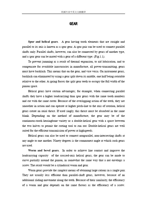
GEARSpur and helical gears. A gear having tooth elements that are straight and parallel to its axis is known as a spur gear. A spur pair can be used to connect parallel shafts only. Parallel shafts, however, can also be connected by gears of another type, and a spur gear can be mated with a gear of a different type. (Fig.1.1).To prevent jamming as a result of thermal expansion, to aid lubrication, and to compensate for avoidable inaccuracies in manufacture, all power-transmitting, gears must have backlash. This means that on the gear, and vice versa. On instrument gears, backlash can eliminated by using a gear split down its middle, one half being rotatable relative to the other. A spring forces the split gear teeth to occupy the full width of the pinion space.Helical gears have certain advantages; for example, when connecting parallel shafts they have a higher loadcarrying than spur gears with the same tooth numbers and cut with the same cutter. Because of the overlapping action of the teeth, they are smoother in action and can operate at higher pitch-line to the axis of rotation, helical gears create an axial thrust. If used singly, this thrust must be absorbed in the same blank. Depending on the method of manufacture, the gear may be of the continuous-tooth herringbone variety or a double-helical gear with a space between the two halves to permit the cutting tool to run out. Double-helical gears are well suited for the efficient transmission of power at highspeeds.Helical gears can also be used to connect nonparallel, non-intersecting shafts at any angle to one another. Ninety degrees is the commonest angle at which such gears are used.Worm and bevel gears.In order to achieve line contact and improve the loadcarrying capacity of the crossed-axis helical gears, the gear can be made to curve partially around the pinion, in somewhat the same way that a nut envelops a screw. The result would be a cylindrical worm and gear.Worm gears provide the simplest means of obtaining large rations in a single pair. They are usually less efficient than parallel-shaft gears, however, because of an additional sliding movement along the teeth. Because of their similarity, the efficiency of a worm and gear depends on the same factors as the efficiency of a screw.Single-thread worms of large diameter have small lead angles and low efficiencies. Multiple-thread worms have larger lead angles and higher efficiencies(Fig.1.2) For transmitting rotary motion and torque around corners, bevel gears are commonly used. The connected shafts, whose axes would intersect if extended, are usually but not necessarily at right angles to one another.When adapted for shafts that do not intersect, spiral bevel gears are called hypoid gears. The pitch surfaces of these gears are not rolling cones, and the ratio of their mean diameters is not equal to the speed Consequently, the pinion may have few teeth and be made as large as necessary to carry the load.The profiles of the teeth on bevel gears are not involutes; they are of such a shape that the tools for the teeth are easier to make and maintain than involute cutting tools. Since bevel gears come in, as long as they are conjugate to one another they need not be conjugate to other gears with different both numbers.1 Early History of GearingThe earliest written descriptions of gears are said to have been made by Aristotle in the fourth century B.C. It has been pointed out that the passage attributed to Aristotle by some was actually from the writings of his school, in “Mechanical P roblems of Aristotle”(Ca.280 B.C). In the passage in question, there was no mention of gear teeth on the parallel wheels, and they may just as well have been smooth wheels in frictional contact. Therefore, the attribution of gearing to Aristotle is, most likely, incorrect.The real beginning of gearing was probably with Archimedes who about 250 B.C. invented the endless screw turning a toothed wheel, which was used in engines of war. Archimedes also used gears to simu-early forms of wagon mileage indicators (odometer) and surveying instruments. These devices were probably “thought” experiments of Heron of Alexandria (ca. A.D.60), who wrote on the subjects of theoretical mechanics and the basic elements of mechanism. The oldest surviving relic containing gears is the Antikythera mechanism, so named because of the Greek island of that name near which the mechanism was discovered in a sunken ship in 1900. Professor Price of Yale University has written an authoritative account of this mechanism. The mechanism is not only the earliest relic of gearing, but it also is anextremely complex arrangement of epicyclic differential gearing. The mechanism is identified as a calendrical computing mechanism for the sun and moon, and has been dated to about 87 B.C.The art of gearing was carried through the European dark ages after the fall of Rome, appearing in Islamic instruments such as the geared astrolabes which were used to calculate the positions of the celestial bodies. Perhaps the art was relearned by the clock-and instrument-making artisans of fourteenth-century Europe, or perhaps some crystallizing ideas and mechanisms were imported from the East after the crusades of the eleventh through the thirteenth centuries.It appears that the English abbot of St.Alban’s monas tery, born Richard of Wallingford, in A.D. 1330, reinvented the epicyclic gearing concept. He applied it to an astronomical clock, which he began to build at that time and which was completed after his death.A mechanical clock of a slightly later period was conceived by Giovanni de Dondi(1348-1364). Diagrams of this clock, which did not use differential gearing, appear in the sketchbooks of Leonardo da Vinci, who designed geared mechanisms himself. In 1967 two of da Vinci’s manuscripts, lost in the Nationa l Library in Madrid since 1830, were rediscovered. One of the manuscripts, written between 1493 and 1497 and known as “Codex Madrid I” , contains 382 pages with some 1600 sketches. Included among this display of Lenardo’s artistic skill and engineering abi lity are his studies of gearing. Among these are tooth profile designs and gearing arrangements that were centuries ahead of their “invention”.2 Beginning of Modern Gear TechnologyIn the period 1450 to 1750, the mathematics of gear-tooth profiles and theories of geared mechanisms became established. Albrecht Durer is credited with discovering the epicycloidal shape(ca. 1525). Philip de la Hire is said to have worked out the analysis of epicycloids and recommended the involute curve for gear teeth (ca. 1694). Leonard Euler worked out the law of conjugate action(ca.1754). Gears deigned according to this law have a steady speed ratio.Since the industrial revolution in mid-nineteenth century, the art of gearing blossomed, and gear designs steadily became based on more scientific principles. In 1893 Wilfred Lewis published a formula for computing stress in gear teeth. This formula is in wide use today in gear design. In 1899 George B.Grant, the founder of five gear manufacturing companies, published “A Treatise on Gear Wheels” . Newinventions led to new applications for gearing. For example, in the early part of this century (1910), parallel shaft gears were introduced to reduce the speed of the newly developed reaction steam turbine enough to turn the driving screws of ocean-going vessels. This application achieved an overall increase in efficiency of 25 percent in sea travel.The need for more accurate and quiet-running gears became obvious with the advent of the automobile. Although the hypoid gear was within our manufacturing capabilities by 1916, it was not used practically until 1926, when it was used in the Packard automobile. The hypoid gear made it possible to lower the drive shaft and gain more usable floor space. By 1937 almost all cars used hypoid-geared rear axles. Special lubricant antiwear additives were formulated in the 1920s which made it practical to use hypoid gearing. In 1931 Earle Buchingham, chairman of an American Society of Mechanical Engineers (ASME) research committee on gearing, published a milestone report on gear-tooth dynamic loading. This led to a better understanding of why faster-running gears sometimes could not carry as much load as slower-running gears.High-strength alloy steels for gearing were developed during the 1920s and 1930s . Nitriding and case-hardening was introduced in 1950. Extremely clean steels produced by vacuum melting processes introduced in1960 have proved effective in prolonging gear life.Since the early 1960s there has been increased use of industrial gas turbines for electric power generation. In the range of 1000 to 14000 hp, epicyclic gear systems have been used successfully. Pitch-line velocities are form 50 to 100m/s(10000 to 20000 ft/min). These gear sets must work reliably for 10000 to 30000 hp between overhaule.In 1976 bevel gears produced to drive a compressor test stand ran stand ran successfully for 235h at 2984kw and 200m/s. form all indications these gears could be used in an industrial application if needed. A reasonable maximum pitch-line velocity for commercial spiral-bevel gears with curved teeth is 60m/s.Gear system development methods have been advanced in which lightweight, highly loaded gears are used in aircraft applications. The problems of strength and dynamic loads, as well as resonant frequencies for such gearing, are now treatable with techniques such as finite-element analysis, siren and impulse testing for mode shapes, and application of damping treatments where required.齿轮直齿轮和斜齿轮轮齿是直的、而方向又与其轴平行的齿轮称作直齿轮。
机械零件齿轮中英文对照外文翻译文献
(文档含英文原文和中文翻译)中英文资料对照外文翻译Machine Parts (I)GearsGears are direct contact bodies, operating in pairs, that transmit motion and force from one rotating shaft to another or from a shaft to a slide (rack), by means of successively engaging projections called teeth.Tooth profiles. The contacting surfaces of gear teeth must be aligned in such a way that the drive is positive; i.e., the load transmitted must not depend on frictional contact. As shown in the treatment of direct contact bodies, this requires that thecommon normal to the surfaces not to pass through the pivotal axis of either the driver or the follower.As it is known as direct contact bodies, cycloidal and involute profiles profiles provide both a positive drive and a uniform velocity ratio;i.e., conjugate action.Basic relations. The smaller of a gear pair is called the pinion and the larger is the gear. When the pinion is on the driving shaft the pair is called the pinion and the larger is the gear. When the pinion is on the driving shaft the pair acts as a speed reducer; When the gear drives, the pair is a speed incrreaser. Gears are more frequently used to reduce speed than to increase it.If a gear having N teeth rotates at n revolutions per minute, the product N*n has the dimension “teeth per minute”. This product must be the same for both members of a mating pair if each tooth acquires a partner from the mating gear as it passes through the region of tooth engagement.For conjugate gears of all types, the gear ratio and the speed ratio are both given by the ratio of the number of teeth on the gear to the number of teeth on the pinion. If a gear has 100 teeth and a mating pinion has 20, the ratio is 100/20=5. Thus the pinion rotates five times as fast as the gear, regardless of the gear. Their point of tangency is called the pitch point, and since it lies on the line of centers, it is the only point at which the profiles have pure roling contact. Gears on nonparallel, non-intersecting shafts also have pitch circles, but the rolling-pitch –circle concept is not valid.Gear types are determined largely by the disposition of the shafts; in addition, certain types are better suited than others for large speed changes. This means that if a specific disposition of the shafts is required, the type of gear will more or less be fixed. On the other hand, if a required speed change demands a certain type, the shaft positions will also be fixed.Spur gears and helical gears. A gear having tooth elements that are straight and parallel to its axis is known as a spur gear. A spur pair can be used to connect parallel shafts only.If an involute spur pinion were made of rubber and twisted uniformly so that the ends rotated about the axis relative to one another, the elements of the teeth, initially straight and parallel to the axis, would become helices. The pinion then in effect would become a helical gear.Worm and bevel gears. In order to achieve line contact and improve the load carrying capacity of the crossed axis helical gears, the gear can be made to curvepartially around the pinion, in somewhat the same way that a nut envelops a screw. The result would be a cylindrical worm and gear. Worms are also made in the shape of an hourglass, instead of cylindrical, so that they partially envelop the gear. This results in a further increase in load-carrying capacity.Worm gears provide the simplest means of obtaining large ratios in a single pair. They are usually less efficient than parallel-shaft gears, however, because of an additional sliding movement along the teeth.V-beltThe rayon and rubber V-belt are widely used for power transmission. Such belts are made in two series: the standard V-belt and the high capacity V-belt. The belts can be used with short center distances and are made endless so that difficulty with splicing devices is avoided.First, cost is low, and power output may be increased by operating several belts side by side. All belts in the drive should stretch at the same rate in order to keep the load equally divided among them. When one of the belts breaks, the group must usually be replaced. The drive may be inclined at any angle with tight side either top or bottom. Since belts can operate on relatively small pulleys, large reductions of speed in a single drive are possible.Second,the included angle for the belt groove is usually from 34°to 38°.The wedging action of the belt in the groove gives a large increase in the tractive force developed by the belt.Third,pulley may be made of cast iron, sheet steel, or die-cast metal. Sufficient clearance must be provided at the bottom of the groove to prevent the belt from bottoming as it becomes narrower from wear. Sometimes the larger pulley is not grooved when it is possible to develop the required tractive force by running on the inner surface of the belt. The cost of cutting the grooves is thereby eliminated. Pulleys are on the market that permit an adjustment in the width of the groove. The effective pitch diameter of the pulley is thus varied, and moderate changes in the speed ratio can be secured.Chain DrivesThe first chain-driven or “safety” bicycle appeared in 1874, and chains were used for driving the rear wheels on early automobiles. Today, as the result of modern design and production methods, chain drives that are much superior to their prototypes are available, and these have contributed greatly to thedevelopment of efficient agricultural machinery, well-drilling equipment, and mining and construction machinery. Since about 1930 chain drives have become increasingly popular, especially for power saws, motorcycle, and escalators etc.There are at least six types of power-transmission chains; three of these will be covered in this article, namely the roller chain, the inverted tooth, or silent chain, and the bead chain. The essential elements in a roller-chain drive are a chain with side plates, pins, bushings (sleeves), and rollers, and two or more sprocket wheels with teeth that look like gear teeth. Roller chains are assembled from pin links and roller links. A pin link consists of two side plates connected by two pins inserted into holes in the side plates. The pins fit tightly into the holes, forming what is known as a press fit. A roller link consists of two side plates connected by two press-fitted bushings, on which two hardened steel rollers are free to rotate. When assembled, the pins are a free fit in the bushings and rotate slightly, relative to the bushings when the chain goes on and leaves a sprocket.Standard roller chains are available in single strands or in multiple strands, In the latter type, two or more chains are joined by common pins that keep the rollers in the separate strands in proper alignment. The speed ratio for a single drive should be limited to about 10∶1; the preferred shaft center distance is from 30 to 35 times the distance between the rollers and chain speeds greater than about 2500 feet (800 meters) per minute are not recommended. Where several parallel shafts are to be driven without slip from a single shaft, roller chains are particularly well suited.An inverted tooth, or silent chain is essentially an assemblage of gear racks, each with two teeth, pivotally connected to form a closed chain with the teeth on the inside, and meshing with conjugate teeth on the sprocket wheels. The links are pin-connected flat steel plates usually having straight-sided teeth with an included angle of 60 degrees. As many links are necessary to transmit the power and are connected side by side. Compared with roller-chain drives, silent-chain drives are quieter, operate successfully at higher speeds, and can transmit more load for the same width. Some automobiles have silent-chain camshaft drives.Bead chains provide an inexpensive and versatile means for connecting parallel or nonparallel shafts when the speed and power transmitted are low. The sprocket wheels contain hemispherical or conical recesses into which the beads fit. The chains look like key chains and are available in plain carbon and stainless steel and also in the form of solid plastic beads molded on a cord. Bead chains are used oncomputers, air conditioners, television tuners, and Venetian blinds. The sprockets may be steel, die-cast zinc or aluminum, or molded nylon.Machine Parts (II)FastenerFasteners are devices which permit one part to be joined to a second part and, hence, they are involved in almost all designs.There are three main classifications of fasteners, which are described as follows:(1) Removable. This type permits the parts to be readily disconnected without damaging the fastener. An example is the ordinary nut-and-bolt fastener.(2) Semi permanent. For this type, the parts can be disconnected, but some damage usually occurs to the fastener. One such example is a cotter pin.(3) Permanent. When this type of fastener is used, it is intended that the parts will never be disassembled. Examples are riveted joints and welded joints.The importance of fasteners can be realized when referring to any complex product. In the case of the automobile, there are literally thousands of parts which are fastened together to produce the total product. The failure or loosening of a single fastener could result in a simple nuisance such as a door rattle or in a serious situation such as a wheel coming off. Such possibilities must be taken into account in the selection of the type of fastener for the specific application.Nuts, bolts, and screws are undoubtedly the most common means of joining materials. Since they are so widely used, it is essential that these fasteners attain maximum effectiveness at the lowest possible cost. Bolts are, in reality, carefully engineered products with a practically infinite use over a wide range of services.An ordinary nut loosens when the forces of vibration overcome those of friction. In a nut and lock washer combination, the lock washer supplies an independent locking feature preventing the nut from loosening. The lock washer is useful only when the bolt might loosen because of a relative change between the length of the bolt and the parts assembled by it. This change in the length of the bolt can be caused by a number of factors-creep in the bolt, loss of resilience, difference in thermal expansion between the bolt and the bolted members, or wear. In the above static cases, the expanding lock washer holds the nut under axial load and keeps the assembly tight. When relative changes are caused by vibration forces, the lock washer is not nearly as effective.Rivets are permanent fasteners. They depend on deformation of their structure for their holding action. Rivets are usually stronger than the thread-type fastener and are more economical on a first-cost basis. Rivets are driven either hot or cold,depending upon the mechanical properties of the rivet material. Aluminum rivets, for instance, are cold-driven, since cold working improves the strength of aluminum. Most large rivets are hot-driven, however.ShaftVirtually all machines contain shafts. The most common shape for shafts is circular and the cross section can be either solid or hollow (hollow shafts can result in weight savings).Shafts are mounted in bearings and transmit power through such devices as gears, pulleys, cams and clutches. These devices introduce forces which attempt to bend the shaft; hence, the shaft must be rigid enough to prevent overloading of the supporting bearings. In general, the bending deflection of a shaft should not exceed 0.01 in. per ft. of length between bearing supports.For diameters less than 3 in., the usual shaft material is cold-rolled steel containing about 0.4 percent carbon. Shafts are either cold-rolled or forged in sizes from 3 in. to 5 in. .For sizes above 5 in. , shafts are forged and machined to size. Plastic shafts are widely used for light load applications. One advantage of using plastic is safety in electrical applications, since plastic is a poor conductor of electricity.Another important aspect of shaft design is the method of directly connecting one shaft to another. This is accomplished by devices such as rigid and flexible couplings.BearingA bearing can be defined as a member specifically designed to support moving machine components. The most common bearing application is the support of a rotating shaft that is transmitting power from one location to another. Since there is always relative motion between a bearing and its mating surface, friction is involved. In many instances, such as the design of pulleys, brakes, and clutches, friction is desirable. However, in the case of bearings, the reduction of friction is one of the prime considerations:Friction results in loss of power, the generation of heat, and increased wear of mating surfaces.The concern of a machine designer with ball bearings and roller bearings is fivefold as follows:(1) Life in relation to load; (2) stiffness, i.e. deflections under load;(3) friction; (4) wear; (5) noise. For moderate loads and speeds the correct selection ofa standard bearing on the basis of load rating will usually secure satisfactoryperformance. The deflection of the bearing elements will become important where loads are high, although this is usually of less magnitude than that of the shafts or other components associated with the bearing. Where speeds are high special cooling arrangements become necessary which may increase frictional drag. Wear is primarily associated with the introduction of contaminants, and sealing arrangements must be chosen with regard to the hostility of the environment.Notwithstanding the fact that responsibility for the basic design of ball bearings and roller bearings rests with the bearing manufacturer, the machine designer must form a correct appreciation of the duty to be performed by the bearing and be concerned not only with bearing selection but with the conditions for correct installation.The fit of the bearing races onto the shaft or onto the housings is of critical importance because of their combined effect on the internal clearance of the bearing as well as preserving the desired degree of interference fit. Inadequate interference can induce serious trouble from fretting corrosion. The inner race is frequently located axially by abutting against a shoulder. A radius at this point is essential for the avoidance of stress concentration and ball races are provided with a radius or chamfer to allow space for this.A journal bearing, in its simplest form, is a cylindrical bushing made of a suitable material and containing properly machined inside and outside diameters. The journal is usually the part of a shaft or pin that rotates inside the bearing.Journal bearings operate with sliding contact, to reduce the problems associated with sliding friction in journal bearings, a lubricant is used in conjunction with compatible mating materials. When selecting the lubricant and mating materials, one must take into account bearing pressures, temperatures and also rubbing velocities. The principle function of the lubricant in sliding contact bearings is to prevent physical contact between the rubbing surfaces. Thus the maintenance of an oil film under varying loads, speeds and temperature is the prime consideration in sliding contact bearings.Introduction to Machinery DesignMachinery design is either to formulate an engineering plan for the satisfaction of a specified need or to solve an engineering problem. It involves a range of disciplines in materials, mechanics, heat, flow, control, electronics and production.Machinery design may be simple or enormously complex, easy or difficult, mathematical or nonmathematical, it may involve a trivial problem or one of great importance. Good design is the orderly and interesting arrangement of an idea to provide certain results or effects. A well-designed product is functional, efficient, and dependable. Such a product is less expensive than a similar poorly designed product that does not function properly and must constantly be repaired.People who perform the various functions of machinery design are typically called industrial designers. He or she must first carefully define the problem, using an engineering approach, to ensure that any proposed solution will solve the right problem. It is important that the designer begins by identifying exactly how he or she will recognize a satisfactory alternative, and how to distinguish between two satisfactory alternatives in order to identify the better. So industrial designers must have creative imagination, knowledge of engineering, production techniques, tools, machines, and materials to design a new product for manufacture, or to improve an existing product.In the modern industrialized world, the wealth and living standards of a nation are closely linked with their capabilities to design and manufacture engineering products. It can be claimed that the advancement of machinery design and manufacturing can remarkably promote the overall level of a country’s industrization. Our country is playing a more and more vital role in the global manufacturing industry. To accelerate such an industrializing process, highly skilled design engineers having extensive knowledge and expertises are needed.Machinery ComponentsThe major part of a machine is the mechanical system. And the mechanical system is decomposed into mechanisms, which can be further decomposed into mechanical components. In this sense, the mechanical components are the fundamental elements of machinery. On the whole, mechanical components can be classified as universal and special components. Bolts, gear, and chains are the typical examples of the universal components, which can be used extensively in different machines across various industrial sectors. Turbine blades, crankshaft and aircraftpropeller are the examples of the special components, which are designed for some specific purposes.Mechanical Design ProcessProduct design requires much research and development. Many concepts of an idea must be studied, tried, refined, and then either used or discarded. Although the content of each engineering problem is unique, the designers follow the similar process to solve the problems.Recognition of NeedSometimes, design begins when a designer recognizes a need and decides to do something about it. The need is often not evident at, all; recognition is usually triggered by a particular adverse circumstance or a set of random circumstances, which arise almost simultaneously. Identification of need usually consists of an undefined and vague problem statement.Definition of ProblemDefinition of problem is necessary to fully define and understand the problem, after which it is possible to restate the goal in a more reasonable and realistic way than the original problem statement. Definition of the problem must include all the specifications for the thing that is to be designed. Obvious items in the specifications are the speeds, feeds, temperature limitations, maximum range, expected variation in the variables, and dimensional and weight limitations.SynthesisThe synthesis is one in which as many alternative possible design approaches are sought, usually without regard for their value or quality. This is also sometimes called the ideation and invention step in which the largest possible number of creative solutions is generated. The synthesis activity includes the specification of material, addition of geometric features, and inclusion of greater dimensional detail to the aggregate design.AnalysisAnalysis is a method of determining or describing the nature of something by separating it into its parts. In the process the elements, or nature of the design, are analyzed to determine the fit between the proposed design and the original design goals.EvaluationEvaluation is the final proof of a successful design and usually involves thetesting of a prototype in the laboratory. Here we wish to discover if the design really satisfies the needs.The above description may give an erroneous impression that this process can be accomplished in a linear fashion as listed. On the contrary, iteration is required within the entire process, moving from any step back to any previous step, in all possible combinations, and doing this repeatedly.PresentationCommunicating the design to others is the finial, vital presentation step in the design process. Basically, there are only three means of communication. These are the written, the oral, and the graphical forms. A successful engineer will be technically competent and versatile in all three forms of communication. The competent engineer should not be afraid of the possibility of not succeeding in a presentation. In fact, the greatest gains are obtained by those willing to risk defeat.Contents of Machinery DesignMachinery design is an important technological basic course in mechanical engineering education. Its objective is to provide the concepts, procedures, data, and decision analysis techniques necessary to design machine elements commonly found in mechanical devices and systems; to develop engineering students’ competence of machine design that is the primary concern of machinery manufacturing and the key to manufacture good products.Machinery design covers the following contents:Provides an introduction to the design process, problem formulation, safety factors.Reviews the material properties and static and dynamic loading analysis, including beam, vibration and impact loading.Reviews the fundamentals of stress and defection analysis.Introduces static failure theories and fracture-mechanics analysis for static loads.Introduces fatigue-failure theory with the emphasis on stress-life approaches to high-cycle fatigue design, which is commonly used in the design of rotation machinery.Discusses thoroughly the phenomena of wear mechanisms, surface contact stresses, and surface fatigue.Investigates shaft design using the fatigue-analysis techniques.Discusses fluid-film and rolling-element bearing theory and application.Gives a thorough introduction to the kinematics, design and stress analysis of spur gears, and a simple introduction to helical, bevel, and worm gearing.Discusses spring design including helical compression, extension and torsion springs.Deals with screws and fasteners including power screw and preload fasteners.Introduces the design and specification of disk and drum clutches and brakes.机械零件(I)齿轮齿轮是直接接触,成对工作的实体,在称为齿的凸出物的连续啮合作用下,齿轮能将运动和力从一个旋转轴传递到另一个旋转轴,或从一个轴传递到一个滑块(齿条)。
【机械类文献翻译】齿轮简介

机械专业中英文文献翻译The Introduction of the gearsIn the force analysis of spur gears, the forces are assumed to act in a single plane. We shall study gears in which the forces have three dimensions. The reason for this, in the case of helical gears, is that the teeth are not parallel to the axis of rotation. And in the case of bevel gears, the rotational axes are not parallel to each other. There are also other reasons, as we shall learn.Helical gears are used to transmit motion between parallel shafts. The helix angle is the same on each gear, but one gear must have a right-hand helix and the other a left-hand helix. The shape of the tooth is an involute helicoid. If a piece of paper cut in the shape of a parallelogram is wrapped around a cylinder, the angular edge of the paper becomes a helix. If we unwind this paper, each point on the angular edge generates an involute curve. The surface obtained when every point on the edge generates an involute is called an involute helicoid.The initial contact of spur-gear teeth is a line extending all the way across the face of the tooth. The initial contact of helical gear teeth is a point, which changes into a line as the teeth come into more engagement. In spur gears the line of contact is parallel to the axis of the rotation; in helical gears, the line is diagonal across the face of the tooth. It is this gradual of the teeth and the smooth transfer of load from one tooth to another, which give helical gears the ability to transmit heavy loads at high speeds. Helical gears subject the shaft bearings to both radial and thrust loads. When the thrust loads become high or are objectionable for other reasons, it may be desirable to use double helical gears. A double helical gear (herringbone) is equivalent to two helical gears of opposite hand, mounted side by side on the same shaft. They develop opposite thrust reactions and thus cancel out the thrust load. When two or more single helical gears are mounted on the same shaft, the hand of the gears should be selected so as to produce the minimum thrust load.Crossed-helical, or spiral, gears are those in which the shaft centerlines are neither parallel nor intersecting. The teeth of crossed-helical fears have point contact with each other, which changes to line contact as the gears wear in. For this reason they will carry out very small loads and are mainly for instrumental applications, and are definitely notrecommended for use in the transmission of power. There is on difference between a crossed helical gear and a helical gear until they are mounted in mesh with each other. They are manufactured in the same way. A pair of meshed crossed helical gears usually have the same hand; that is ,a right-hand driver goes with a right-hand driven. In the design of crossed-helical gears, the minimum sliding velocity is obtained when the helix angle are equal. However, when the helix angle are not equal, the gear with the larger helix angle should be used as the driver if both gears have the same hand.Worm gears are similar to crossed helical gears. The pinion or worm has a small number of teeth, usually one to four, and since they completely wrap around the pitch cylinder they are called threads. Its mating gear is called a worm gear, which is not a true helical gear. A worm and worm gear are used to provide a high angular-velocity reduction between nonintersecting shafts which are usually at right angle. The worm gear is not a helical gear because its face is made concave to fit the curvature of the worm in order to provide line contact instead of point contact. However, a disadvantage of worm gearing is the high sliding velocities across the teeth, the same as with crossed helical gears.Worm gearing are either single or double enveloping. A single-enveloping gearing is one in which the gear wraps around or partially encloses the worm.. A gearing in which each element partially encloses the other is, of course, a double-enveloping worm gearing. The important difference between the two is that area contact exists between the teeth of double-enveloping gears while only line contact between those of single-enveloping gears. The worm and worm gear of a set have the same hand of helix as for crossed helical gears, but the helix angles are usually quite different. The helix angle on the worm is generally quite large, and that on the gear very small. Because of this, it is usual to specify the lead angle on the worm, which is the complement of the worm helix angle, and the helix angle on the gear; the two angles are equal for a 90-deg. Shaft angle.When gears are to be used to transmit motion between intersecting shaft, some of bevel gear is required. Although bevel gear are usually made for a shaft angle of 90 deg. They may be produced for almost any shaft angle. The teeth may be cast, milled, or generated. Only the generated teeth may be classed as accurate. In a typical bevel gear mounting, one of the gear is often mounted outboard of the bearing. This means that shaftdeflection can be more pronounced and have a greater effect on the contact of teeth. Another difficulty, which occurs in predicting the stress in bevel-gear teeth, is the fact the teeth are tapered.Straight bevel gears are easy to design and simple to manufacture and give very good results in service if they are mounted accurately and positively. As in the case of squr gears, however, they become noisy at higher values of the pitch-line velocity. In these cases it is often good design practice to go to the spiral bevel gear, which is the bevel counterpart of the helical gear. As in the case of helical gears, spiral bevel gears give a much smoother tooth action than straight bevel gears, and hence are useful where high speed are encountered.It is frequently desirable, as in the case of automotive differential applications, to have gearing similar to bevel gears but with the shaft offset. Such gears are called hypoid gears because their pitch surfaces are hyperboloids of revolution. The tooth action between such gears is a combination of rolling and sliding along a straight line and has much in common with that of worm gears.齿轮简介在直齿圆柱齿轮的受力分析中,是假定各力作用在单一平面的。
外文文献翻译 中英文对照 机械类 齿轮和轴的介绍--毕业设计论文

译文原文题目:gear and shaft introduce 译文题目:齿轮和轴的介绍学院:机电工程学院专业班级:机械工程及自动化06级(3)班学生姓名:齿轮和轴的介绍摘要:在传统机械和现代机械中齿轮和轴的重要地位是不可动摇的。
齿轮和轴主要安装在主轴箱来传递力的方向。
通过加工制造它们可以分为许多的型号,分别用于许多的场合。
所以我们对齿轮和轴的了解和认识必须是多层次多方位的。
关键词:齿轮;轴在直齿圆柱齿轮的受力分析中,是假定各力作用在单一平面的。
我们将研究作用力具有三维坐标的齿轮。
因此,在斜齿轮的情况下,其齿向是不平行于回转轴线的。
而在锥齿轮的情况中各回转轴线互相不平行。
像我们要讨论的那样,尚有其他道理需要学习,掌握。
斜齿轮用于传递平行轴之间的运动。
倾斜角度每个齿轮都一样,但一个必须右旋斜齿,而另一个必须是左旋斜齿。
齿的形状是一溅开线螺旋面。
如果一张被剪成平行四边形(矩形)的纸张包围在齿轮圆柱体上,纸上印出齿的角刃边就变成斜线。
如果我展开这张纸,在血角刃边上的每一个点就发生一渐开线曲线。
直齿圆柱齿轮轮齿的初始接触处是跨过整个齿面而伸展开来的线。
斜齿轮轮齿的初始接触是一点,当齿进入更多的啮合时,它就变成线。
在直齿圆柱齿轮中,接触是平行于回转轴线的。
在斜齿轮中,该先是跨过齿面的对角线。
它是齿轮逐渐进行啮合并平稳的从一个齿到另一个齿传递运动,那样就使斜齿轮具有高速重载下平稳传递运动的能力。
斜齿轮使轴的轴承承受径向和轴向力。
当轴向推力变的大了或由于别的原因而产生某些影响时,那就可以使用人字齿轮。
双斜齿轮(人字齿轮)是与反向的并排地装在同一轴上的两个斜齿轮等效。
他们产生相反的轴向推力作用,这样就消除了轴向推力。
当两个或更多个单向齿斜齿轮被在同一轴上时,齿轮的齿向应作选择,以便产生最小的轴向推力。
交错轴斜齿轮或螺旋齿轮,他们是轴中心线既不相交也不平行。
交错轴斜齿轮的齿彼此之间发生点接触,它随着齿轮的磨合而变成线接触。
机械原理英文版3齿轮
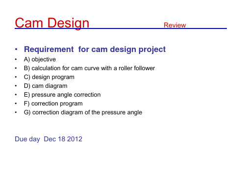
formula deduction
●Check pressure angle for roller follower check the case of self-lock ●Size of cam and follower
Cam Design
pinion
GEAR
Driving gear Transmission ratio
Cam Design
GEAR
Time varying output function
Noncircuilar Gear--printing press
Cam Design
GEAR
No slip in transmission
Synchronous belt –timing belt in automobile
30
45
●Equal divide base circle ●Envelope of tangent line ●Direction
review
Key points in cam chapter
● SVAJ curve ● graphical method for cam diagram ●Calculate coordinate for 3 typical cam
out d in mv in d out
Torque ratio?
Driven gear Spur Gear (直齿轮) external set
Cam Design
out d in mv in d out
GEAR
Rack and pinion
mv
put d in in d out
translation Internal set Spur Gear
行星齿轮中英文对照外文翻译文献

行星齿轮中英文对照外文翻译文献(文档含英文原文和中文翻译)原文:Planetary GearsIn troduct ionThe Tamiya pla netary gearbox is drive n by a small DC motor that runs at about 10,500 rpm on 3.0V DC and draws about 1.0A. The maximum speed ratio is 1:400, givi ng an output speed of about 26 rpm. Four pla netary stages are supplied with the gearbox, two 1:4 and two 1:5, and any comb in ati on can be selected. Not only is this a good drive for small mechanical applications, it provides an excellent review of epicycle gear trains. The gearbox is a very well-desig ned plastic kit that can be assembled in about an hour with very few tools. The source for the kit is give n in the Refere nces.Let's beg in by review ing the fun dame ntals of geari ng, and the trick of an alyz ing epicyclic gear trains.Epicyclic Gear TrainsA pair of spur gears is represented in the diagram by their pitch circles , which are tangent at the pitch point P. The meshing gear teeth extend beyond the pitch circle by the addendum, and the spaces between them have a depth ben eath the pitch circle by the dede ndum. If the radii of the pitch circles are a and b, the dista nee betwee n the gear shafts is a + b. In the action of the gears, the pitch circles roll on one ano ther without slipp ing. To en sure this, the gear teeth must have a proper shape so that whe n the driv ing gear moves uniformly, so does the driven gear. This means that the line of pressure, normal to the tooth profiles in con tact, passes through the pitch point. Then, the tran smissi on of power will be free of vibrati on and high speeds are possible. We won't talk further about gear teeth here, havi ng stated this fun dame ntal prin ciple of geari ng.If a gear of pitch radius a has N teeth, the n the dista nee betwee n corresp onding points on successive teeth will be 2 n a/N, atyqtx a lntid the circular pitch . If two gears are to mate, the circular pitches must be the same. The pitch is usually stated as the rati on 2a/N, called the diametral pitch . If you count the number of teeth on a gear, then the pitch diameter is the number of teeth times the diametral pitch. If you know the pitch diameters of two gears, the n you can specify the dista nee betwee n the shafts.The velocity ratio r of a pair of gears is the ratio of the angular velocity of the driven gear to the angular velocity of the driving gear. By the condition of rolling of pitch circles, r = -a/b = -N 1/N2, since pitch radii are proportional to the number of teeth. The angular velocity n of the gears may be given in radians/sec, revoluti ons per minute (rpm), or any similar un its. If we take one direct ion of rotati on as positive, the n the other direct ion is n egative. This is the reas on for the (-) sig n in the above expressi on. If one of the gears is internal (having teeth on its inner rim), then the velocity ratio is positive, since the gears will rotate in the same direct ion.The usual in volute gears have a tooth shape that is tolera nt of variati ons in the dista nce betwee n the axes, so the gears will run smoothly if this dista nce is not quite correct. The velocity ratio of the gears does not depe nd on the exact spac ing of the axes, but is fixed by the nu mber of teeth, or what is the same thi ng,by the pitch diameters. Slightly increasing the distanee above its theoretical value makes the gears run easier, since the cleara nces are larger. On the other hand, backlash is also in creased, which may not be desired in some applicati ons.An epicyclic gear train has gear shafts mounted on a moving arm or carrier that can rotate about the axis, as well as the gears themselves. The arm can be an in put eleme nt, or an output eleme nt, and can be held fixed or allowed to rotate. The outer gear is the ring gear or annu lus. A simple but very com mon epicyclic train is the sun-and-planet epicyclic train, shown in the figure at the left. Three planetary gears are used for mechanical reasons; they may be considered as one in describing the action of the gearing. The sun gear, the arm, or the ring gear may be in put or output lin ks.If the arm is fixed, so that it cannot rotate, we have a simple train of three gears. Then, n 2M1 = -N1/N2,n3/n2 = +N 2/N3, and n/n1 = -N 1/N3. This is very simple, and should not be confusing. If the arm is allowed to move, figuring out the velocity ratios taxes the human intellect. Attempting this will show the truth of the stateme nt; if you can man age it, you deserve praise and fame. It is by no means impossible, just in voved. However, there is a very easy way to get the desired result. First, just con sider the gear train locked, so it moves as a rigid body, arm and all. All three gears and the arm then have a unity velocity ratio. The trick is that any motion of the gear train can carried out by first holding the arm fixed and rotating the gears relative to one another, and then locking the train and rotating it about the fixed axis. The net motion is the sum or difference of multiples of the two separate motions that satisfies the conditions of the problem (usually that one eleme nt is held fixed). To carry out this program, con struct a table in which the an gular velocities of the gears and arm are listed for each, for each of the two cases. The locked train gives 1, 1, 1, 1 for arm, gear 1, gear 2 and gear 3. Arm fixed gives 0, 1, -N 1/N2, -N1/N3. Suppose we want the velocity rati on betwee n the arm and gear 1, whe n gear 3 is fixed. Multiply the first row by a con sta nt so that whe n it is added to the sec ond row, the velocity of gear 3 will be zero. This con sta nt is N 1/N3. Now, doing one displaceme nt and the n the other corresp onds to addi ng the two rows. We find N 1/N3, 1 + N 1/N3, N1/N3 - N1/N2.The first nu mber is the arm velocity, the sec ond the velocity of gear 1, so the velocity ratio betwee n them is N〃(N1 + N3), after multiplying through by N 3. This is the velocity ratio we need for the Tamiya gearbox, where the ring gear does not rotate, the sun gear is the in put, and the arm is the output. The procedure is general, however, and will work for any epicyclic train.One of the Tamiya planetary gear assemblies has N1 = N2 = 16, N3 = 48, while the other has N 1 = 12, N2 = 18, N 3 = 48. Because the planetary gears must fit between the sun and ring gears, the condition N 3 = N1 + 2N2 must be satisfied. It is in deed satisfied for the nu mbers of teeth give n. The velocity ratio of the first set will be 16/(48 + 16) = 1/4. The velocity ratio of the seco nd set will be 12/(48 + 12) = 1/5. Both ratios are as advertised. Note that the sun gear and arm will rotate in the same directi on.The best gen eral method for solvi ng epicyclic gear trains is the tabular method, since it does not contain hidden assumptions like formulas, nor require the work of the vector method. The first step is to isolate the epicyclic train, separat ing the gear trains for in puts and outputs from it. Find the in put speeds or turns, using the in put gear trains. There are, in gen eral, two in puts, one of which may be zero in simple problems. Now prepare two rows of the table of turns or angular velocities. The first row corresponds to rotating around the epicyclic axis once, and consists of all 1's. Write down the second row assuming that the arm velocity is zero, using the known gear ratios. The row that you want is a lin ear comb in ati on of these two rows, with unknown multipliers x and y. Summing the en tries for the in put gears gives two simulta neous lin ear equatio ns for x and y in terms of the known in put velocities. Now the sum of the two rows multiplied by their respective multipliers gives the speeds of all the gears of in terest. Fin ally, find the output speed withthe aid of the output gear train. Be careful to get the directi ons of rotatio n correct, with respect to a direct ion take n as positive.The Tamiya Gearbox KitThe parts are best cut from the sprues with a flush-cutter of the type used in electr onics. The very small bits of plastic remaining can then be removed with a sharp X-acto knife. Carefully remove all excess plastic, as the in struct ions say.Read the in struct ions carefully and make sure that things are the right way up and in the correct relative posit ons. The gearbox un its go together easily with light pressure. Note that the brow n ones must go together in the correct relative orientation. The 4mm washers are the ones of which two are supplied, and there is also a full-size draw ing of one in the in structi ons. The smaller washers will not fit over the shaft, any way. The output shaft is metal. Use larger long-nose pliers to press the E-ring into positi on in its groove in front of the washer. There is a picture show ing how to do this. There was an extra E-ri ng in my kit. The three prongs fit into the carriers for the pla netary gears, and are drive n by them.Now stack up the gearbox un its as desired. I used all four, being sure to put a 1:5 unit on the end n ext to the motor. Therefore, I n eeded the long screws. Press the orange sun gear for the last 1:5 un it firmly on the motor shaft as far as it will go. If it is not well-seated, the motor clip will not close. It might be a good idea to put some lubricant on this gear from the tube included with the kit. If you use a different lubricant, test it first on a piece of plastic from the kit to make sure that it is compatible. A dry graphite lubricant would also work quite well. This should spread lubrica nt on all parts of the last un it, which is the one subject to the highest speeds. Put the motor in place, gently but firmly, wiggling it so that the sun gear meshes. If the sun gear is not meshed, the motor clip will not close. Now put the motor term in als in a vertical column, and press on the motor clamp.The reverse of the in struct ions show how to attach the drive arm and gives some hints on use of the gearbox. I got an extra spri ng pin, and two extra 3 mm washers. If you have some small washers, they can be used on the mach ine screws holdi ng the gearbox together. Eno ugh torque is produced at the output to damage things (up to 6 kg-cm), so make sure the output arm can rotate freely. I used a sta ndard laboratory DC supply with variable voltage and current limiting, but dry cells could be used as well. The current drain of 1 A is high even for D cells, so a power supply is in dicated for serious use. The in structi ons say not to exceed 4.5V, which is good advice. With 400:1 reduction, the motor should run freely whatever the output load.My gearbox ran well the first time it was tested. I timed the output revolutions with a stopwatch, and found 47s for 20 revolutions, or 25.5 rpm. This corresponds to 10,200 rpm at the motor, which is close to specifications. It would be easy to connect another gearbox in series with this one (parts are included to make this possible), and get about 4 revolutions per hour. Still another gearbox would produce about one revolution in four days. This is an excellent kit, and I recommend it highly.Other Epicyclic Trai nsA very famous epicyclic cha in is the Watt sun-an d-pla net gear, pate nted in 1781 as an alter native to the crank for converting the reciprocati ng motio n of a steam engine into rotary moti on .It was inven ted by William Murdoch. The crank, at that time, had bee n pate nted and Watt did not want to pay royalties. An in cide ntal adva ntage was a 1:2 in crease in the rotative speed of the output. However, it was more expe nsive than a crank, and was seldom used after the crank pate nt expired. Watch the ani mati on on Wikipedia.The in put is the arm, which carries the pla net gear wheel mat ing with the sun gear wheel of equal size. The planet wheel is prevented from rotating by being fastened to the connecting rod. It oscillates a little, but always retur ns to the same place on every revoluti on. Using the tabular method expla ined above, the firstline is 1, 1, 1 where the first number refers to the arm, the second to the planet gear, and the third to the sun gear. The sec ond line is 0, -1, 1, where we have rotated the pla net one tur n an ticlockwise. Addi ng, we get 1,0, 2, which means that one revolution of the arm (one double stroke of the engine) gives two revolutions of the sun gear.We can use the sun-and-planet gear to illustrate another method for analyzing epicyclical trains in which we use velocities. This method may be more satisfying than the tabular method and show more clearly how the train works. In the diagram at the right, A and O are the cen tres of the pla net and sun gears, respectively. A rotates about O with an gular velocity 1, which we assum e clockwise. At the positi onshow n, this gives A a v elocity 2 1 upward, as show n. Now the pla net gear does not rotate, so all points in it move with the same velocity as A. This in cludes the pitch point P, which is also a point in the sun gear, which rotates about the fixed axis O with an gular velocity 2. Therefore, 2 =2 <ej, the same result as with the tabular method.The diagram at the left shows how the velocity method is applied to the pla netary gear set treated above. The sun and pla net gears are assumed to be the same diameter (2 un its). The ring gear is the n of diameter 6. Let us assume the sun gear is fixed, so that the pitch point P is also fixed. The velocity of point A is twice the angular velocity of the arm. Since P is fixed, P' must move at twice the velocity of A, or four times the velocity of the arm. However, the velocity of P' is three times the angular velocity of the ring gear as well, so that 3 r = 4 ee If the arm is the in put, the velocity ratio is the n 3:4, while if the ring is the in put, the velocity ratio is 4:3.A three-speed bicycle hub may contain two of these epicyclical trai ns, with the ring gears conn ected (actually, com mon to the two trai ns). The in put from the rear sprocket is to the arm of one train, while the output to the hub is from the arm of the sec ond train .It is possible to lock one or both of the sun gears to the axle, or else to lock the sun gear to the arm and free of the axle, so that the train gives a 1:1 ratio. The three gears are: high, 3:4, output train locked; middle, 1:1, both trains locked, and low, 4:3 in put train locked. Of course, this is just one possibility, and many differe nt variable hubs have bee n manu factured. The pla netary variable hub was in troduced by Sturmey-Archer in 1903. The popular AW hub had the ratios men ti oned here.Chain hoists may use epicyclical trains. The ring gear is stati on ary, part of the main hous ing. The in put is to the sun gear, the output from the pla net carrier. The sun and pla net gears have very differe nt diameters, to obta in a large reducti on ratio.The Model T Ford (1908-1927) used a reverted epicyclic transmission in which brake bands applied to the shafts carrying sun gears selected the gear ratio. The low gear ratio was 11:4 forward, while the reverse gear ratio was -4:1. The high gear was 1:1. Reverted means that the gears on the planet carrier shaft drove other gears on shafts concentric with the main shaft, where the brake bands were applied. The floor controls were three pedals: low-n eutral-high, reverse, tran smissi on brake. The hand brake applied stopped the left-hand pedal at neutral. The spark advance and throttle were on the steering column.The automotive differe ntial, illustrated at the right, is a bevel-gear epicyclic train. The pinion drives the ring gear (crow n wheel) which rotates freely, carry ing the idler gears. Only one idler is n ecessary, but more than one gives better symmetry. The ring gear corresponds to the planet carrier, and the idler gears to the pla net gears, of the usual epicyclic cha in. The idler gears drive the side gears on the half-axles, which correspond to the sun and ring gears, and are the output gears. When the two half-axles revolve at the same speed, the idlers do not revolve. When the half-axles move at different speeds, the idlers revolve. The differential applies equal torque to the side gears (they are driven at equal distances by the idlers) while allowing them to rotate at differe nt speeds. If one wheel slips, it rotates at double speed while the other wheel does not rotate. The same (small) torque is, n evertheless, applied to both wheels.The tabular method is easily used to an alyze the an gular velocities. Rotat ing the cha in as a whole gives 1,0, 1, 1 for ring, idler, left and right side gears. Holding the ring fixed gives 0, 1, 1, -1. If the right side gear is held fixed and the ring makes one rotation, we simply add to get 1, 1,2, 0, which says that the left side gear makes two revolutions. The velocity method can also be used, of course. Considering the (equal) forces exerted on the side gears by the idler gears shows that the torques will be equal.Refere ncesTamiya Planetary Gearbox Set, Item 72001-1400. Edmund Scientific, Catalog No. C029D, item D30524-08 ($19.95).C. Carmichael, ed., Kent's Mechanical Engineer's Handbook , 12th ed. (New York: John Wiley and Sons, 1950). Design and Production Volume, p.14-49 to 14-43.V. L. Doughtie, Eleme nts of Mecha nism, 6th ed. (New York: John Wiley and So ns, 1947). pp. 299-311. Epicyclic gear. Wikipedia article on epicyclic trains.Sun and planet gear. Includes an animation.行星齿轮机构简介Tamiya行星轮变速箱由一个约10500 r/min,3.0V , 1.0A的直流电机运行。
齿轮可修改全文
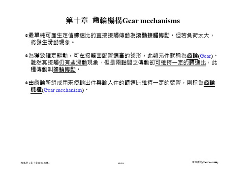
但是過量的背隙,則會產生傳動不精確與顫
振等問題。
(10.4)
(b) 圖10.6 正齒輪與齒形名稱
機構學 (第十章齒輪 機構)
10-10
東華書局(YAN-hs/1999)
[例10-1]有一正齒輪,齒數(T)為32、徑節(Pd)為4、轉速(n)為300rpm,試求這個 齒輪的周節(Pc)與節線速度(Vp)。
柱,兩傳動軸的旋轉方向相反,大的稱齒輪(Gear),小的稱小齒輪(Pinion)。 ➢ 內齒輪(Internal gear)為小齒輪在一個較大齒輪內面接觸,其中大齒輪又稱
環齒輪(Annular or ring gear),兩傳動軸旋轉的方向相同。 ◎齒條(Rack)可視為半徑無窮大的齒輪,與其嚙合的齒輪為小齒輪,相當於一
須通過中心線上的一個固定點,即節點。
◎一對嚙合齒輪,若符合齒輪傳動基本定律,則稱其相對運動為共軛作用 (Conjugate action)。
機構學 (第十章齒輪 機構)
10-12
東華書局(YAN-hs/1999)
◎設主動輪的角速度為2、從動輪的角速度為3,則轉速比為常數:
rv
3 2
n3 n2
T2 T3
◎冠狀齒輪(Crown gear)當兩個斜齒輪軸線間的夾角大於90時其中之一節圓錐 角等於直角,節曲面成為一平面,稱為冠狀齒輪(Crown gear)。
◎蝸線斜齒輪(Spiral bevel gear)之齒形為曲線,具有不同的螺旋角,齒數可比直 齒斜齒輪少。蝸線斜齒輪由於接觸齒數增加,加以接觸由齒面的一端逐漸行
部、圓心在齒輪中心的最小圓。
齒根(Dedendum):節圓與齒根圓的徑
向距離。
(b) 圖10.6 正齒輪與齒形名稱
齿轮的发展英文作文

齿轮的发展英文作文下载温馨提示:该文档是我店铺精心编制而成,希望大家下载以后,能够帮助大家解决实际的问题。
文档下载后可定制随意修改,请根据实际需要进行相应的调整和使用,谢谢!并且,本店铺为大家提供各种各样类型的实用资料,如教育随笔、日记赏析、句子摘抄、古诗大全、经典美文、话题作文、工作总结、词语解析、文案摘录、其他资料等等,如想了解不同资料格式和写法,敬请关注!Download tips: This document is carefully compiled by theeditor. I hope that after you download them,they can help yousolve practical problems. The document can be customized andmodified after downloading,please adjust and use it according toactual needs, thank you!In addition, our shop provides you with various types ofpractical materials,such as educational essays, diaryappreciation,sentence excerpts,ancient poems,classic articles,topic composition,work summary,word parsing,copyexcerpts,other materials and so on,want to know different data formats andwriting methods,please pay attention!Gears have been around for a long time. They are really important in machines.You see gears in all kinds of things, from cars to clocks. They make things work smoothly.Some gears are big and some are small. And they all have different jobs to do.Without gears, a lot of things we use every daywouldn't work right. It's amazing how useful they are.。
英语原文(1)齿轮

AbstractAfter 11,300 h of operation, one of the axles of the reduction gearbox of the hoist mechanism of a dockside crane faileddue to the propagation of a fatigue crack. The axle contained two gears, the largest of which was mounted swith a key, while the smallest gear was an integral part of the axle. On both ends of the axle a bearing was mounted: one cylindricalbearing and one spherical roller bearing (locating bearing).The axle was made from 17CrNiMo6 steel, and the machined gear teeth were case carburised. The failure of theaxle occurred in the middle between both bearings of the axle, on a non-contacting part of the gear machined on the axle.During visual inspection striations were observed on the fracture surface and three separate crack initiation zones couldbe observed on three neighbouring gear teeth. The ratio of final fracture versus fatigue fracture was low, indicating a lownominal stress on the axle.The three initiation sites were investigated with optical microscopy and SEM, and clear indications of a ductile overloadfracture were found. In an etched longitudinal section of one of the gear teeth where initiation took place several crackscould be observed in the hardened case of the tooth. The hardness at the initiation site was found to be 777 HV, while the hardness at the final fracture (diametric position relative to the initiation of the crack) was found to be lower, namely 722 HV.It was concluded that at the initiation site during the case carburisation quenching cracks were formed, which then propagated through the whole section of the axle under relatively low operation load._ 2006 Elsevier Ltd. All rights reserved.Keywords: Cranes; Gear tooth failures; Quench cracks; Carburisation1. ApplicationThe hoist mechanism of a dockside crane is driven by an electric motor through a reduction gearbox. Thegearbox has a total reduction of 24.92 and is designed for a nominal driving torque of 3800 Nm (with an1350-6307/$ - see front matter _ 2006 Elsevier Ltd. All rights reserved.doi:10.1016/j.engfailanal.2006.11.030engine speed of 850 rpm). After 11,300 h of operation of the hoist mechanism the axle connecting the first andthe second stage of the gearbox was found to have failed. 图The fractured parts of the axle are shown in Fig. 1. The gear visible on the left of Fig. 1 is an integral part ofthe axle and belongs to the second stage of the transmission. The teeth of this gear are case carburised. On thepart shown on the right in Fig. 1 a gear of the second stage of the transmission was mounted, connected to theaxle by means of a keyway (not shown in Fig. 1). Both the left and the right part of the failed axle contain a bearing seat (visible in the bottom of Fig. 1). On the left part a non-locating cylindrical roller bearing is normally mounted, while on the right part a (locating) spherical roller bearing is mounted. As shown in Fig. 1 theaxle failed due to a crack in the middle between both bearings. This crack is situated on a non-contacting part of the gear machined on the axle.2. Visual observationsBoth crack faces are shown in Fig. 2 (left part of Fig. 1) and in Fig. 3 (right part of Fig. 1). On bothcrack faces striations indicating a fatigue crack are clearly visible. Also visible on both crack faces are some dark temper coloured zones, which are most probable due to the use of a blowtorch duringdismounting.When the crack face shown in Fig. 3 is investigated more closely, three different initiation sites can be discerned (marked A, A0 and A00 in Fig. 3). Final fracture of the axle is located at the site marked B in Fig. 3. Thedark tempercoloured band extending between C and C0 in Fig.3 is most probable damage produced by the useof a blowtorch during dismounting. A fourth possible initiation site is marked D in Fig. 3. The fatigue crack propagated through the axle starting from A, A0 and A00 towards B. The ratio of the surface occupied by the fatigue crack and the surface occupied by the final fractureindicates that the nominal working stress of theaxle was low, as the final fracture surface occupies only a small part of the total crack surface [1]. The distribution of the striation lines over the fatigue crack surface and the location of the final fracture indicate that the axle was mainly loaded in rotating bending [1].图3. Micrographs – scanning electron microscopyThe fracture surface at the initiation site on tooth A00 is shown under magnification in Fig. 4. On this toothtwo different zones can be discerned. At the top of the tooth a dull zone with a fibrous aspect is visible. The图aspect of this zone is typical for a ductile fracture. The shiny patches in this zone are most probably caused by relative movement of the crack faces during operation of the gearbox. The crack face on the rest of the tooth isflat and has a lustrous aspect typical for a fatigue crack. The three teeth A, A0 and A00 were removed by a grinding operation under cooling. Tooth A00 is shown inFig. 5 and tooth A and A0 in Fig. 6 (A in front). On the face of tooth A00 two cracks can be discerned, togetherwith a crack on the top of the tooth. The face of tooth A is chipped (centre of image) and three cracks arevisible on the face of this tooth.Fig. 7 shows a composite image of two etched micrographs from a longitudinal cross section of tooth A00.Multiple cracks in the hardened case of the tooth are clearly visible in this figure. These cracks do not extend further than the case of the tooth.For reference the tooth at the final fracture (marked B in Fig. 3) was also removed by grinding. An etchedoptical micrograph from a longitudinal cross section of this tooth is shown in Fig. 8. In this tooth no crackscould be observed in the hardened case. There is however one crack visible at the root of the tooth B, but thiscrack is most probably caused by the final fracture of the axle. This is borne out by Fig. 9, which shows ahigher magnification etched micrograph of the material around the crack at the root of tooth B. From thisfigure it is clear that the material around this crack is plastically deformed in a significant way (dark zonesin the vicinity of the crack tip).A number of scanning electron micrographs were made from thecrack face. Fig. 10a–c were taken on thecrack face at tooth A00. Fig. 10a, b were taken in the fibrous zone visible on the tooth. Fig. 10a shows a mainly intercrystalline fracture although some aspects of plastic deformation are visible. The fracture surface ofFig. 10b is typical for a ductile fracture. The highest peaks of this fracture surface are flattened, most probablyby relative movement of the two crack faces after the fracture occurred.Fig. 10c was taken in the lustrous zone visible on the crack face of tooth A00. Very little can be discerned inthis figure, as most of the crack face is flattened. Fig. 10d shows a scanning electron micrograph of the chipped tooth A. The aspect of this fracture is typical for a ductile fracture.图4. Metal structure and hardnessFrom the longitudinal cross sections of the teeth A00 (see Fig. 7) and B (see Fig. 8) a number of high magnification micrographs were taken to evaluate the metal structure. The metal structure of the axle in the vicinity of tooth A00 (Fig. 11a) is a mainly pearlitic structure, withsome residual austenite (white patches). The material of the tooth A00 outside of the hardened case presentsa bainitic structure (Fig. 11b) while in the hardened case a martensitic structure could be observed(Fig. 11c). The Vickers hardness of the material of tooth A00 was measured and is shown in Table 1 as a function of the distance from the tooth top.The metal structure of the axle in the vicinity of tooth B is a mainly pearlitic structure, with some residual austenite. This is comparable to tooth A00. The material of the tooth B outside of the hardened case presents a图bainitic structure while in the hardened case a martensitic structure could be observed. While the bainiticstructure of tooth B is comparable to that of tooth A00, the martensitic structure of tooth B contains moreretained austenite and a finer martensitic structure. The Vickers hardness of the material of tooth B was measured and is shown in Table 2 as a function of thedistance from the tooth top.5. DiscussionVisual inspection of the crack face indicated that the axlefailed due to a fatigue crack, which propagatedunder a rotating bending load. The nominal stress on the axle was low (small ratio of final fracture to fatiguecrack). From the orientation of the fatigue striations three different initiation sites could be found on three successive teeth (A, A0 and A00). When these teeth were removed from the axle by a grinding operation a numberof cracks could be observed on the face of these teeth and the face of tooth was found to be chipped.The crack face at the initiation sites showed a fibrous aspect, which is typical for a ductile fracture. Micrographicand SEM investigation of the initiation sites corroborated this. The fracture face at the chipped toothA also showed a fibrous aspect indicating a ductile fracture.A longitudinal cross section of tooth A00 showedmultiple cracks in the hardened case of the tooth. One of these cracks served as the initiation site for a fatigue crack, which then propagated through the section of the axle. For reference a longitudinal cross section oftooth B (at the location of the final fracture) was produced. For this tooth no cracks were found in the caseof the tooth, although one crack at the root of the tooth was observed. A high magnification micrograph ofthis cracked showed significant plastic deformation at the site of this crack, so this crack most probably arose from the final fracture of the axle.This indicates that the failure of the axle is due to the cracks found at the teeth A, A0 and A00, of which a number propagated under fatigue loading of the axle. The aspect of the initiating cracks indicates that these were formed during the production of the axle and specifically during the case carburisation process and subsequentquenching (quenching cracks). Quenching cracks may occur from a mismatched material and heattreatment procedure or from excessive or uneven quenching [2].The origin of these quenching cracks does not lie with the chemical composition of the material. Accordingto the specification of the manufacturer the material of the axle should conform to 17CrNiMo6. Table 3 showsthe chemical composition as measured for the axle, together with the upper and lower limits imposed by thespecification of 17CrNiMo6 from [3]. It is clear that the material composition is within the limits of the specification.This material is also commonly used for the production of case carburised machine elements, so thefirst possible reason for the occurrence of quenching cracks supplied above is probably not the cause of the quenching cracks.Another possible explanation for the occurrence of quenching cracks is uneven or excessive quenching. The observed material structures provide some clues that this might have caused the quenching cracks. The metal structure observed in the cross section of tooth A00 is typical for a case carburised steel. The same structure was found in tooth B at the location of the final fracture although the hardness of tooth B was significantly lower than the hardness of tooth A. The metal structure of the case of tooth B contained somewhat more retainedaustenite and a finer martensitic structure than tooth A00. The hardness measured in the case of tooth A00 is somewhat on the high side. It is also clear that for tooth A00 the case extends to the nose of the tooth (leftin Fig. 7), while it does not for tooth B (see Fig. 8). This indicates differences in the carburisation and/or quenching between tooth A00 and tooth B. The cause for these differences remain unknown as no records fromthe manufacturer could be obtained. It is however clear that the root cause of the failure lies with anomalies occurring during the case carburisation and subsequent quenching of the gear of the axle.6. Conclusions1. The axle failed due to a fatigue crack, which propagated under rotating bending load with low nominalstress.2. At the initiation sites of the fatigue crack a ductile fracture face was found.3. The teeth at which the fatigue crack originated contained multiple cracks, one of which served as the initiation site for the fatigue crack. These multiple cracks are formed during the quenching operation.4. It is clear that the origin of the quenching cracks does not lie with the material composition, but is entirely due to anomalies, which occurred during the case carburisation and subsequent quenching operations.References[1] Fatigue design handbook, SAE, Warrendale PA, 1988, ISBN 0-89883-011-7.[2] Tallian TE. Failure atlas for hertz contact machine elements. New York: ASME press; 1992, ISBN 0-7918-0008-3.[3] Wegst C, Wegst M. Stahlschlu¨ ssel. 20th ed. Marbach: Verlag Stahlschlu¨ ssel Wegst; 2004, ISBN 3-922599-20-6.。
- 1、下载文档前请自行甄别文档内容的完整性,平台不提供额外的编辑、内容补充、找答案等附加服务。
- 2、"仅部分预览"的文档,不可在线预览部分如存在完整性等问题,可反馈申请退款(可完整预览的文档不适用该条件!)。
- 3、如文档侵犯您的权益,请联系客服反馈,我们会尽快为您处理(人工客服工作时间:9:00-18:30)。
Helical, Worm and Bevel GearsGears are machine elements that transmit motion by means of successively engaging teeth. Gears transmit motion from one rotating shaft to another, or to a rack that translates. Numerous applications exist in which constant angular velocity ratio (or constant torque ratio) must be transmitted between shafts. Based on the variety of gear types available, there is no restriction that the input and the output shafts need be either in-line or parallel. Nonlinear angular velocity ratios are also available by using noncircular gears. In order to maintain a constant angular velocity, the individual tooth profile must obey the fundamental law of gearing: for a pair of gears to transmit a constant angular velocity ratio, the shape of their contacting profiles must be such that the common normal passes through a fixed point on the line of the centers.Any two mating tooth profiles that satisfy the fundamental law of gearing are called conjugate profiles. Although there are many tooth shapes possible in which a mating tooth could be designed to satisfy the fundamental law, only two are in general use: the cycloidal and involute profiles. The involute has important advantages: it is easy to manufacture and the center distance between a pair of involute gears can be varied without changing the velocity ratio. Thus close tolerances between shafts are not required when utilizing the involute profile.There are several standard gear types. For applications with parallel shafts, straight spur gear, parallel helical, or herringbone gears are usually used. In the case of interesting shafts, straight bevel or spiral bevel gears are employed. For nonintersecting and nonparallel shafts, crossed helical, worm, face, skew bevel or hypoid gears would be acceptable choices. For spur gears, the pitch circles of mating gears are tangent to each other. They roll on one another without sliding. The addendum is the height by which a tooth projects beyond the pitch circle (also the radial distance between the pitch circle and the addendum circle). The clearance is the amount by which the dedendum (tooth height below the pitch circle) in a given gear exceeds the addendum of its mating gear. The tooth thickness is the distance across the tooth along the arc of the pitch circle while the tooth space is the distance between adjacent teeth along the arc of the pitch circle. The backlash is the amount by which the width of the tooth space exceeds the thickness of the engaging tooth at the pitchcircle.The initial contact of spur-gear teeth is a line extending all the way across the face of the tooth. The initial contact of helical gear teeth is a point,which changes into a line as the teeth come into more engagement. In spur gears the line of contact is parallel to the axis of the rotation;in helical gears,the line is diagonal across the face of the tooth. It is this gradual engagement of the teeth and the smooth transfer of load from one tooth to another which give helical gears the ability to transmit heavy loads at high speeds. Helical gears subject the shaft bearings to both radial and thrust loads. When the thrust loads become high or are objectionable for other reasons, it may be desirable to use double helical gears. A double helical gear (herringbone) is equivalent to two helical gears of opposite hand, mounted side by side on the same shaft. They develop opposite thrust reactions and thus cancel out the thrust load. When two or more single helical gears are mounted on the same shaft,the hand of the gears should be selected so as to produce the minimum thrust load.Worm gears are similar to crossed helical gears .The pinlon or worm has a small number of teeth, usually one to four, and since they completely wrap around the pitch cylinder they are called threads. Its mating gear is called a worm gear, which is not a true helical gear. A worm and worm gear are used to provide a high angular-velocity reduction between nonintersecting shafts which are usually at right angle. The worm gear is not a helical gear because its face is made concave to fit the curvature of the worm in order to provide line contact instead of point contact instead of point contact. However, a disadvantage of worm gearing is the high sliding velocities across the teeth, the same as with crossed helical gears.Worm gearing are either single-or double-enveloping. A single-enveloping is one in which the gear wraps around or partially encloses the worm. A gearing in each element partially encloses the other is, of course, a double-enveloping worm gearing. The important difference between the two is that area contact exists between the teeth of double-enveloping gears while only line contact between those of single-enveloping gears. The worm and gear of a set have the same hand of helix as for crossed helical gears, but the helix angle are usually quiet different. The helix angle on the worm is generally quiet large, and that on the gear very small. Because of this, it is usual tospecify the lead angle on the worm, which is the complement of the worm helix angle, and the helix angle on the gear; the two angles are equal for a 90-deg.shaft angle.When gears are to be used to transmit motion between intersecting shafts, some form of bevel gear is required. Although bevel gears are usually made for a shaft angle of 90 deg., they may be produced for almost any shaft angle. The teeth may be cast, milled, or generated. Only the generated teeth may be classed as accurate. In a typical bevel gear mounting, one of the gear is often mounted outboard of the bearing. This means that shaft deflection can be more pronounced and have a greater effect on the contact of the teeth. Another difficulty, which occurs in predicting the stress in bevel-gear teeth, is the fact that the teeth are tapered.Straight bevel gears are easy to design and simple to manufacture and give very good results in service if they are mounted accurately and positively. As in the case of spur gears, however, they become noisy at higher values of the pitch-line velocity. In these cases it is often good design practice to go to the spiral bevel gear, which is the bevel counterpart of the helical gear. As in the case of helical gears, spiral bevel gears give a much smoother tooth action than straight bevel gears, and hence are useful where high speed are encountered.It is frequently desirable, as in the case of automotive differential applications, to have gearing similar to bevel gears but with the shaft offset. Such gears are called hypoid gears because their pitch surfaces are hyperboloids of revolution. The tooth action between such gears is a combination of rolling and sliding along a straight line and has much in common with that of worm gears.斜齿轮,蜗杆和圆锥齿轮齿轮是通过轮齿连续啮合的方式传递运动的机器零件。