recon floor参数连网说明
捷顺门禁系统操作说明

捷顺门禁系统操作说明服务器IP:192.168.100.9服务器名称:JSMJSVR管理员账号(WIN2008):administrator管理员密码(win2008):jsmjsvr捷顺门禁控制器默认IP:192.168.0.1捷顺门禁服务器数据库登陆信息服务器JSMJSVR\js或192.168.100.9\js数据库:JSOCTNet用户:sa密码:123456客户端安装环境:32位操作系统(XP\WIN7)数据库:SQL2008(客户端需安装SQL2008连接SDK)捷顺一卡通客户端软件捷顺读卡器设置工具(安装包中tool文件夹)捷顺客户端安装操作系统第一次安装时会先行安装安装dotNetFx40运行环境安装完毕后才可安装捷顺一卡通客户端默认方式安装安装加密狗驱动客户端安装完毕后需运行设置软件狗文件将安装文件中jssn文件复制到C盘根目录下,软件狗路径指向此文件打开—保存设置。
设置数据库连接连接参数见下图,测试连接通过后保存连接。
捷顺门禁客户端安装调试完毕捷顺门禁控制器调试部分说明由于捷顺出厂门禁控制器默认IP地址192.168.0.1,与实际使用地址不符,需先行更改默认IP访问http://192.168.0.1打开门禁控制器管理页面将其中的IP地址修改为实际使用地址(以192.168.100.100为例)修改完毕点击”Enter”,捷顺门禁控制器IP地址设置完毕捷顺一卡通系统登陆点击帐号:9999密码:(空)进入系统后选择管理中心----设备资料---设备资料维护选择所需要管理门禁控制器的组织(位置,以在行政楼添加IP地址为192.168.100.100为例)选择------鼠标右键---选择“搜索设备”勾选找到的IP地址192.168.100.100门禁控制器,鼠标右键选择新增设备。
新增加的门禁控制器会出现(根据IP地址顺序)出现在行政楼门禁组织树下方,显示方式为MAC(物理地址)模式鼠标右键---修改修改名称后保存设备资料维护操作完毕捷顺门禁控制器调试管理中心—设置----本地设置方案---“门禁控制器方案”---编辑注意:工作站IP需设置为正在操作客户端电脑的IP地址添加本地管理设备选择“行政楼测试门禁”—确定新增加设备后请保存本地设置方案调试完毕门禁控制器初始化设置完毕捷顺门禁控制器通道设置门禁管理-设备管理—JSE设备管理—“行政楼测试门禁”鼠标右键—新增通道通道设置完毕—确定选择“行政楼测试门禁”—“门100-1”参考以下图中参数设置—确定退出。
爱立信常用无线参数介绍(经典)

爱立信常用无线参数介绍一.小区描叙参数 (1)1.1 CELL (1)1.2 CGI (1)1.3 BSIC (2)1.4 BCCHNO (2)1.5 BCCHTYPE (2)1.6 AGBLK (3)1.7 MFRMS (3)二.邻小区参数 (3)2.1 CELLR (3)2.2 CTYPE (4)2.3 RELATION (4)2.4 CS (4)三.IDLE MODE参数 (5)3.1 ACCMIN (5)3.2 CCHPWR (5)3.3 CRH (6)3.4 NCCPERM (6)3.5 CB (6)3.6 CBQ (7)3.7 MAXRET (7)3.8 ATT (7)3.9 T3212 (7)3.10 CRO (8)3.11 TO (8)3.12 PT (8)四.LOCATING下的参数 (9)4.1 BSPWR (9)4.2 MSRXMIN (9)4.3 BSRXMIN (9)4.4 MSRXSUFF (10)4.5 BSRXSUFF (10)4.6 BSTXPWR (10)4.7 KHYST (11)4.8 TRHYST (11)4.9 KOFFSET (11)4.10 TROFFSET (12)4.11 BQOFFSET (12)4.12 TALIM (12)4.13 QLIMDL (12)4.14 QLIMUL (13)五.功率控制 (13)5.1 DMPSTA TE (13)5.2 SSDES (14)5.3 INIDES...................................................................................... 错误!未定义书签。
5.4 SSLEN (14)5.5 INILEN ..................................................................................... 错误!未定义书签。
Fortinet WiFi网络产品说明说明书
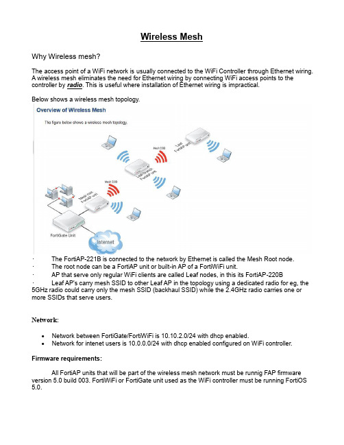
Wireless MeshWhy Wireless mesh?The access point of a WiFi network is usually connected to the WiFi Controller through Ethernet wiring.A wireless mesh eliminates the need for Ethernet wiring by connecting WiFi access points to the controller by radio. This is useful where installation of Ethernet wiring is impractical.Below shows a wireless mesh topology.•The FortiAP-221B is connected to the network by Ethernet is called the Mesh Root node.•The root node can be a FortiAP unit or built-in AP of a FortiWiFi unit.•AP that serve only regular WiFi clients are called Leaf nodes, in this its FortiAP-220B•Leaf AP's carry mesh SSID to other Leaf AP in the topology using a dedicated radio for eg, the 5GHz radio could carry only the mesh SSID (backhaul SSID) while the 2.4GHz radio carries one or more SSIDs that serve users.Network:∙Network between FortiGate/FortiWiFi is 10.10.2.0/24 with dhcp enabled.∙Network for intenet users is 10.0.0.0/24 with dhcp enabled configured on WiFi controller. Firmware requirements:All FortiAP units that will be part of the wireless mesh network must be runnig FAP firmware version 5.0 build 003. FortiWiFi or FortiGate unit used as the WiFi controller must be running FortiOS 5.0.Configuration of meshed WiFi network:Setting up Full Mesh Wireless on FortiGate Unit using two FortiAP Units.∙Configure the mesh SSID, go to WiFi Controller > WiFi Network > SSID.∙Edit the default mesh SSID fmesh.root and change the SSID from the default to something unique. Note that the traffic mode is set to mesh downlink. Enter a new pre-shared key.∙Create another SSID for clients access and use tunnel∙Go to WiFi Controller > WiFi Network > Custom AP Profile and create a new AP profile, or edit the profile created earlier, and enter the follow settings: Select the correct platform, in thisexample we are using the FAP 221B.∙Select Radio 1 and set mode Access Point and use default Band and Channel settings. Enable your SSID and the mesh SSID from the list of available SSIDs.∙Select Radio 2 and set mode Access Point and use default Band and Channel settings.∙Enable your SSID and the mesh SSID from the list of available SSIDs. Click OK.∙If this is a new profile you will need to apply this to your custom AP profile in your managed AP.Go to WiFi Controller > Managed Access Points > Managed FortiAP and select your device and select edit. In the wireless settings change the AP profile from automatic to your new profile and select apply and ok to save your changes.∙This change will cause the access point daemons on the AP to restart.The FortiAP units that will serve as branch/leaf nodes must be preconfigured as follows.∙Connect to the FortiAP unit web-based manager on its default Ethernet interface IP address 192.168.1.2∙In the connectivity section enter the IP address of your AP network as follows∙Start your second AP. Y ou may need to work in pairs for this lab, in that case you have to de-authorizes one AP and then you have to authorizes the second AP The second AP will use theautomatic profile which is fine for this lab.∙Configure the second AP to use the wireless mesh as an uplink. From the FortiAP GUI, go to Connectivity and select mesh and enter the mesh SSID and pre-shared key. This change willcause the access point daemons on the AP to restart.∙Y ou should observe that the second AP connects as a leaf device.Note: It might take some time for the state icon to become green however if you feel it is taking to long ca n you can reboot the AP to expedite the process.∙Y ou have now created the full mesh. If you would like to test that clients on the leaf AP can reach the wireless controller modify the AP profile associated with your root AP and removeyour wireless client SSID so that it is only being announced on the leaf AP.Debug commands:Using the wireless controller debug of the FortiGate, try the following commands. Use the following command to see the status of the FortiAPs:diagnose wireless-controller wlac -c wtpFWF60C3G12006306 # diagnose wireless-controller wlac -c wtp-------------------------------WTP 1----------------------------WTP vd : rootvfid : 0id : FAP22B3U12009906mgmt_vlanid : 0region code : Cregcode status : invalidrefcnt : 3 own(1) wtpprof(1) ws(1)plain_ctl : disableddeleted : noadmin : enablewtp-mode : normalwtp-profile : resv-dflt-FAP22B3U12009906name :location :ip-frag-prevent : TCP_MSStun-mtu : 0,0active sw ver : FAP22B-v5.0-build032local IPv4 addr : 10.10.2.6board mac : 00:09:0f:a1:94:3ejoin_time : Tue Nov 25 11:01:38 2014mesh-uplink : meshmesh hop count : 1parent wtp id : FP221B3X12008432connection state : Connectedimage download progress: 0last failure : 0 -- N/Alast failure param:last failure time: N/Astation info : 0/0geo : World (0)Radio 1 : APcountry name : CNcountry code : 156radio_type : 11N_5Gchannel list : 36 40 44 48 149 153 157 161 165darrp : disabledtxpower : 100% (23 dBm)beacon_intv : 100rts_threshold : 2346frag_threshold : 2346ap scan : disableap scan passive : disabledsta scan : disabledWIDS profile : ---wlan 0 : Mesh_WiFiwlan 1 : leaf_SSIDmax vaps : 8base bssid : 00:09:0f:a1:94:40oper chan : 149station info : 0/0Radio 2 : APcountry name : CNcountry code : 156radio_type : 11Nchannel list : 1 6 11darrp : disabledtxpower : 100% (27 dBm)beacon_intv : 100rts_threshold : 2346frag_threshold : 2346ap scan : disableap scan passive : disabledsta scan : disabledWIDS profile : ---wlan 0 : Mesh_WiFiwlan 1 : leaf_SSIDmax vaps : 8base bssid : 00:09:0f:a1:94:47oper chan : 1station info : 0/0Radio 3 : Not Exist-------------------------------WTP 2---------------------------- WTP vd : rootvfid : 0id : FP221B3X12008432mgmt_vlanid : 0region code : Aregcode status : validrefcnt : 3 own(1) wtpprof(1) ws(1)plain_ctl : disableddeleted : noadmin : enablewtp-mode : normalwtp-profile : myapname :location : N/Aip-frag-prevent : TCP_MSStun-mtu : 0,0active sw ver : FP221B-v5.0-build032local IPv4 addr : 10.10.2.4board mac : 00:09:0f:7c:6c:30join_time : Tue Nov 25 11:00:15 2014mesh-uplink : ethernetmesh hop count : 0parent wtp id :connection state : Connectedimage download progress: 0last failure : 10 -- JOIN REQ from unmanaged WTP is denied last failure param: N/Alast failure time: Tue Nov 25 10:30:07 2014station info : 1/0geo : World (0)Radio 1 : APcountry name : UScountry code : 841radio_type : 11N_5Gchannel list : 36 40 44 48 149 153 157 161 165darrp : disabledtxpower : 100% (23 dBm)beacon_intv : 100rts_threshold : 2346frag_threshold : 2346ap scan : disableap scan passive : disabledsta scan : disabledWIDS profile : ---wlan 0 : Mesh_Linkwlan 1 : leaf_SSIDmax vaps : 8base bssid : 00:09:0f:7c:6c:31oper chan : 36station info : 0/0Radio 2 : APcountry name : UScountry code : 841radio_type : 11Nchannel list : 1 6 11darrp : disabledtxpower : 100% (27 dBm)beacon_intv : 100rts_threshold : 2346frag_threshold : 2346ap scan : disableap scan passive : disabledsta scan : disabledWIDS profile : ---wlan 0 : Mesh_Linkwlan 1 : leaf_SSIDmax vaps : 8base bssid : 00:09:0f:7c:6c:38oper chan : 1station info : 1/0Radio 3 : Not Exist-------------------------------WTP 3----------------------------WTP vd : rootvfid : 0id : FWF60C-WIFI0mgmt_vlanid : 0region code : ALLregcode status : validrefcnt : 3 own(1) wtpprof(1) ws(1)plain_ctl : disableddeleted : noadmin : enablewtp-mode : normalwtp-profile : resv-dflt-FWF60C-WIFI0name :location :ip-frag-prevent : TCP_MSStun-mtu : 0,0active sw ver : FWF60C-v5.0-build292local IPv4 addr : 127.0.0.1board mac : 00:09:0f:00:00:01join_time : Mon Nov 24 12:37:52 2014mesh-uplink : ethernetmesh hop count : 0parent wtp id :connection state : Connectedimage download progress: 0last failure : 0 -- N/Alast failure param:last failure time: N/Astation info : 0/0geo : World (0)Radio 1 : APcountry name : UScountry code : N/Aradio_type : 11Nchannel list : 1 6 11darrp : disabledtxpower : 100% (27 dBm)beacon_intv : 100rts_threshold : 2346frag_threshold : 2346ap scan : disableap scan passive : disabledsta scan : disabledWIDS profile : ---max vaps : 8base bssid : 00:0e:8e:41:2e:69oper chan : 1station info : 0/0Radio 2 : Not ExistRadio 3 : Not Exist-------------------------------Total 3 WTPs----------------------------Use the following command to list the configured wireless LANs: diagnose wireless-controller wlac -c wlanFWF60C3G12006306 # diagnose wireless-controller wlac -c wlan WLAN (001/003) vdom,name: root, Mesh_Linkvlanid : 0 (auto vlan intf disabled)sw name :ip, mac : 0.0.0.0, 00:ff:b1:aa:12:39status : uprefcnt, deleted : 3 own(1) wtpprof(2)mesh backhaul : enabledlocal bridging : disabledlocal switching : disableddynamic vlan : disabledauth type : 0mac type : 0xfffffffftunnel type : 0xfffffffffast roaming : 0x1bc suppression : dhcp arpsuppress ssid : 0ssid : fmesh.rootsecurity : 7radius mac auth : disabledradius mac auth svr:auth : 0key :keyindex : 1password : fmeshrootradius_server :usergroup : 0intra privacy : disabledstation info : 1/0kern sock : 23mf acl cfg : disabled, allow, 0 entriessta list 0000 72:09:0f:a1:94:47 ws (0-10.10.2.4:5246) 1 0WTP 0001 : 0, FP221B3X12008432---- 0-10.10.2.4:5246 (12 - CWAS_RUN)WLAN (002/003) vdom,name: root, Mesh_WiFivlanid : 0 (auto vlan intf disabled)sw name :ip, mac : 10.0.0.1, 00:ff:d7:12:eb:8fstatus : downrefcnt, deleted : 3 own(1) wtpprof(2)mesh backhaul : disabledlocal bridging : disabledlocal switching : enableddynamic vlan : disabledauth type : 0mac type : 0xfffffffftunnel type : 0xfffffffffast roaming : 0x1bc suppression : dhcp arpsuppress ssid : 0ssid : fortinet.mesh.rootsecurity : 7radius mac auth : disabledradius mac auth svr:auth : 0key :keyindex : 1password : fortinetradius_server :usergroup : 0intra privacy : disabledstation info : 0/0kern sock : 8mf acl cfg : disabled, allow, 0 entries WTP 0002 : 0, FAP22B3U12009906 ---- 0-10.10.2.6:5246 (12 - CWAS_RUN) WLAN (003/003) vdom,name: root, leaf_SSID vlanid : 0 (auto vlan intf disabled) sw name :ip, mac : 10.0.0.1, 00:ff:50:2f:de:4e status : uprefcnt, deleted : 5 own(1) wtpprof(4)mesh backhaul : disabledlocal bridging : disabledlocal switching : enableddynamic vlan : disabledauth type : 0mac type : 0xfffffffftunnel type : 0xfffffffffast roaming : 0x1bc suppression : dhcp arpsuppress ssid : 0ssid : Client_SSIDsecurity : 7radius mac auth : disabledradius mac auth svr:auth : 0key :keyindex : 1password : fmeshrootradius_server :usergroup : 0intra privacy : disabledstation info : 0/0kern sock : 24mf acl cfg : disabled, allow, 0 entries WTP 0003 : 0, FAP22B3U12009906 ---- 0-10.10.2.6:5246 (12 - CWAS_RUN) WTP 0004 : 0, FP221B3X12008432---- 0-10.10.2.4:5246 (12 - CWAS_RUN)Use the following command to list the connected wireless stations:diagnose wireless-controller wlac -d staFWF60C3G12006306 # diagnose wireless-controller wlac -d sta* vf=0 wtp=15 rId=1 wlan=leaf_SSID ip=0.0.0.0 mac=12:09:0f:7c:6c:31 vci= host= user= group= signal=0 noise=0 idle=23145 bw=0 use=3 chan=36 radio_type=11N_5G security=wpa_wpa2_personal encrypt=aes online=yes* vf=0 wtp=15 rId=2 wlan=leaf_SSID ip=0.0.0.0 mac=12:09:0f:7c:6c:38 vci= host= user= group= signal=0 noise=0 idle=23145 bw=0 use=3 chan=1 radio_type=11N security=wpa_wpa2_personal encrypt=aes online=yesvf=0 wtp=15 rId=2 wlan=leaf_SSID ip=10.0.0.3 mac=00:26:c7:99:33:86 vci=MSFT 5.0 host=Y ogesh-PC user= group= signal=-43 noise=-95 idle=1 bw=0 use=3 chan=1 radio_type=11Nsecurity=wpa2_only_personal encrypt=aes online=yes* vf=0 wtp=16 rId=2 wlan=leaf_SSID ip=0.0.0.0 mac=12:09:0f:a1:94:47 vci= host= user= group= signal=0 noise=0 idle=23061 bw=0 use=3 chan=1 radio_type=11N security=wpa_wpa2_personal encrypt=aes online=yes* vf=0 wtp=16 rId=1 wlan=leaf_SSID ip=0.0.0.0 mac=12:09:0f:a1:94:40 vci= host= user= group= signal=0 noise=0 idle=23062 bw=0 use=3 chan=149 radio_type=11N_5Gsecurity=wpa_wpa2_personal encrypt=aes online=yesvf=0 wtp=15 rId=2 wlan=leaf_SSID ip=10.0.0.2 mac=90:21:55:eb:bf:25 vci= host= user= group= signal=-44 noise=-95 idle=27 bw=0 use=3 chan=1 radio_type=11N security=wpa2_only_personal encrypt=aes online=yes* vf=0 wtp=15 rId=1 wlan=Mesh_Link ip=0.0.0.0 mac=00:09:0f:7c:6c:31 vci= host= user= group= signal=0 noise=0 idle=22187 bw=0 use=3 chan=36 radio_type=11N_5G security=wpa_wpa2_personal encrypt=aes online=yes* vf=0 wtp=15 rId=2 wlan=Mesh_Link ip=0.0.0.0 mac=00:09:0f:7c:6c:38 vci= host= user= group= signal=0 noise=0 idle=22187 bw=0 use=3 chan=1 radio_type=11N security=wpa_wpa2_personal encrypt=aes online=yesm vf=0 wtp=15 rId=2 wlan=Mesh_Link ip=10.10.2.6 mac=72:09:0f:a1:94:47 vci= host= user= group= signal=-28 noise=-95 idle=3 bw=0 use=3 chan=1 radio_type=11N security=wpa2_only_personal encrypt=aes online=yes* vf=0 wtp=16 rId=2 wlan=Mesh_WiFi ip=0.0.0.0 mac=00:09:0f:a1:94:47 vci= host= user= group= signal=0 noise=0 idle=23062 bw=0 use=3 chan=1 radio_type=11N security=wpa_wpa2_personal encrypt=aes online=yes* vf=0 wtp=16 rId=1 wlan=Mesh_WiFi ip=0.0.0.0 mac=00:09:0f:a1:94:40 vci= host= user= group= signal=0 noise=0 idle=23062 bw=0 use=3 chan=149 radio_type=11N_5Gsecurity=wpa_wpa2_personal encrypt=aes online=yesUsing the debug of the FortiAP, try the following commands.View the status of the Wireless clients:Go to WiFi Controller > Monitors > Wireless Health to view the list of all connected internet users.In the FortiAP CLI, you can check the main ip field in the output from the commandscw_diag -c meshFAP22B3U12009906 # cw_diag -c meshSys Cfg AP addr mode: staticstp mode : 0dflt ip : 10.10.2.6dflt mask: 255.255.255.0dflt gw : 10.10.2.10Mesh Cfg Uplink : Mesh UplinkAP SSID : fmesh.rootAP BSSID : 00:00:00:00:00:00AP PASSWD : fmeshrootlocal eth bridge : 2Mesh Oper AP Type : Mesh Uplinkwbh status : runningwbh rId : 1wbh mac : 72:09:0f:a1:94:47wbh bssid : 00:09:0f:7c:6c:38wbh Chan : 1vap mhc : 1eth type : 0x2233main dhcp ip : 0.0.0.0main dhcp mask : 0.0.0.0main dhcp gw : 0.0.0.0bh dhcp ip : 0.0.0.0bh dhcp mask : 0.0.0.0bh dhcp gw : 0.0.0.0main ip : 10.10.2.6main mask : 255.255.255.0main gw : 10.10.2.10bh ip : 0.0.0.0bh mask : 0.0.0.0bh gw : 0.0.0.0bh mac : 00:00:00:00:00:00eth bridge : 2Troubleshooting Guide of Wireless Mesh:Use the following command to list the Authentication process and client connection: diagnose debug application wpad 4diagnose debug enableUse the following command to list specific client process by filtering it with mac-address: diagnose wireless-controller wlac sta_filter <client-mac> 1diagnose debug enableT o turn it off use following commands:diagnose wireless-controller wlac sta_filter <client-mac> 0diagnose debug reset。
锐捷路由器配置手册之欧阳史创编

锐捷路由器配置手册目录:路由器基础:控制台远程登录其它配置方法命令模式命令模式的切换CLI命令的编辑技巧常见CLI错误提示使用 no 和 default 选项查看配置文件保存配置文件删除配置文件备份配置文件文件系统概述文件操作目录操作搭建环境用TFTP传输文件用Xmodem传输文件ROM监控模式路由器的基本配置:配置控制台口令配置远程登录口令配置特权口令以太网接口的一般配置配置多个IP地址配置MAC地址接口信息的查看同步串行口的一般配置配置反转时钟配置链路封装协议配置线路编解码方式忽略DCD信号接口信息的查看回环接口的配置接口信息的查看配置路由:配置静态路由配置默认路由配置缺省网络配置可被动态路由覆盖的静态路由RIP协议的一般配置RIP协议参数的配置OSPF协议的一般配置广域网协议配置:配置接口的HDLC封装配置keepalive时间配置接口的PPP封装配置PPP协商超时时间配置CHAP服务端配置CHAP客户端配置双向CHAP验证配置PAP服务端配置PAP客户端配置双向PAP验证点到点的帧中继配置NAT的配置:静态NAT的配置静态NAPT的配置动态NAT的配置动态NAPT的配置接口动态NAPT的配置外部源地址的静态NAT配置外部源地址的动态NAT配置DHCP的配置:启用DHCP服务器配置DHCP地址池配置选项访问控制列表的配置:标准ACLs的语句规则配置标号的标准ACLs配置命名的标准ACLs扩展ACLs的语句规则配置标号的扩展ACLs配置命名的扩展ACLsMAC扩展ACLs的语句规则配置标号的MAC扩展ACLs配置命名的MAC扩展ACLsExpert扩展ACLs的语句规则配置标号的Expert扩展ACLs配置命名的Expert扩展ACLs带序号的ACLs带时间区的ACLs第一部分路由器基础:路由器的几种配置方法控制台用一台计算机作为控制台和网络设备相连,通过计算机对网络设备进行配置。
1、硬件连接:把Console线一端连接在计算机的串行口上,另一端连接在网络设备的Console口上。
红狮网络产品指南说明书

Ethernet Switches | Cellular M2M Routers & RTUs | Wi-Fi Radios | Communication ConvertersLearn more at 13Learn more at 3Table of ContentsEthernet SolutionsManaged Ethernet SwitchesAdvanced Managed Ethernet Switches Monitored Ethernet Switches Unmanaged Ethernet Switches Power over Ethernet (PoE) Solutions IP67 Switches Wi-Fi Radios Wired RoutersCellular M2M SolutionsCellular RTUs Cellular RoutersCommunication ConvertersSerial Converters Fiber ConvertersAccessoriesEthernet Accessories Cellular Accessories4202118161878232610142224Managed Ethernet SwitchesRed Lion’s rugged, reliable managed industrial Ethernet switches support industry‑standard applications. These hardened switches are ideally suited for harsh industrial environments where real‑time performance under extreme operating conditions is required. Built‑in redundancy and network management ensure communications stay up and running while providing tools for monitoring and tracking.>Layer 2 managed industrial Ethernet switches > R ugged enclosure supports deployment in extreme environments >Powerful network management >Gigabit copper, fiber and SFP optionsNetwork Healing TechnologiesN-Ring ® is a proprietary high‑speed ring technology that providesconsistent healing times of ~20 milliseconds (ms) for up to 250 switches. N-Link ® provides the ability to link two N‑Rings for network redundancy.Real-Time Ring is a highly‑reliable, proprietary ring technology from Sixnet offering 30 ms healing time plus 5 ms per hop.Rapid Spanning Tree Protocol (RSTP) IEEE 802.1w is an industry standard protocol providing ~2‑3 second recovery time and offers asolution for multi‑vendor Ethernet networks.Managed Ethernet Switch ComparisonPartner LinkMasterN-Link SlaveN-Ring 2Red Lion ManagedIndustrial Ethernet Switches45Learn more at NT24k ® Modular Managed Gigabit Ethernet Switches>Hot swappable modules with Fast Ethernet and Gigabit configurations >Robust remote monitoring with N‑View™ monitoring technology >Smart plug‑and‑play operation >DIN‑rail and rackmount options >Extreme environment specificationsSFP ports support 100Base or 1000Base SFP transceivers, which are sold separately. Low-voltage power supplies feature redundant power inputs.Compact NT24k Managed Switches >Fast Ethernet, Gigabit, fiber and SFP models>Robust remote monitoring with N‑View monitoring technology >Smart plug‑and‑play operation >Extreme environment specificationsSFP ports support 100Base or 1000Base SFP transceivers, which are sold separately.Multimode and singlemode options available. FX models available with SC or ST connectors; GX models available with SC style connectors.6Learn more at 700 & 7000 Managed Ethernet Switches>Plug‑and‑play deployment with IGMP auto‑configuration >N‑View monitoring provides real‑time switch diagnostics >Ideally suited to use as N‑Ring or N‑Link managerFAST ETHERNETGIGABIT ETHERNET *KEMA approved IEC 61850-3 and IEEE 1613 HV models available.Fiber models available in multimode and singlemode configurations with SC or ST fiber connectors. SFP ports support 1000Base SFP transceivers, which are sold separately.SLX Managed Ethernet Switches>Versatile networking solutions with copper and fiber models >Real‑time Modbus over Ethernet monitoring >Fast Ethernet and Gigabit port options >DIN‑rail or panel mounting optionsFiber models available in multimode and singlemode configurations with SC or ST fiber connectors. SFP ports support 100Base or 1000Base SFP transceivers, which are sold separately.7Learn more at Advanced Managed Ethernet SwitchesRed Lion’s advanced managed industrial Ethernet switches offer powerful enterprise‑class networking with security options that prevent unauthorized access and enable policy enforcement. These powerful switches provide QoS traffic classification and sophisticated multicast controls, reducing traffic and ensuring real‑time message delivery. The flexible industrial design is built to support the harshest environments.*Rackmount - MetalSFP ports support 100Base or 1000Base SFP transceivers, which are sold separately.EL Advanced Management Ethernet Switches>Layer 3 functionality with enterprise class networking features >Hardened enclosure for harsh industrial applications >Up to 10G ports for high‑bandwidth backhaul >Advanced security control8Monitored Ethernet SwitchesRed Lion’s monitored industrial Ethernet switches providenetwork performance monitoring with Modbus or N‑Viewmonitoring technology. These rugged, compact switches arebuilt for mission‑critical applications and provide cost‑effectivenetwork monitoring options that can be integrated directly intoany industrial control system.>Layer 2 unmanaged industrial switches>Network performance monitoring via Modbus or N‑View technology>Versatile networking solutions>Copper and fiber port configurations>Hardened for the toughest applicationsMonitored Ethernet Switch Comparison500-A Monitored Process Control Switches>Advanced management features include IGMP snooping, VLAN,QoS and Port Mirroring>N‑View monitoring provides real‑time switch diagnostics>Rugged industrial DIN‑rail and rackmount optionsFiber models available in multimode and singlemode configurations with SC or ST fiber connectors.9Learn more at SL & SLX Fast Ethernet Ring Switches>Fast, fault‑tolerant Real‑Time Ring network redundancy >Pre‑configured for plug‑and‑play ring functionality >Redundant power inputs>Real‑time Modbus over Ethernet monitoringFiber models available in multimode and singlemode configurations with SC or ST fiber connectors.300 & 500 Monitored Fast Ethernet Switches >High reliability in industrial applications >Plug‑and‑play operation>N‑View monitoring provides real‑time switch diagnosticsFAST ETHERNETFiber models available in multimode and singlemode configurations with SC or ST fiber connectors.10Unmanaged Ethernet SwitchesRed Lion’s industrial unmanaged Ethernet switches offer powerful network performance with plug‑and‑play functionality. With an endless range of port options, these unmanaged switches are set to tackle the demands of industrial data acquisition, control and Ethernet I/O applications.>Compact IEEE 802.3 Layer 2 industrial switches >Automatic speed, duplex and cable sensing >Designed for use in mission‑critical applications >Plug‑and‑play functionalityUnmanaged Ethernet Switch Comparison*2015 data is forecastedIndustrial Ethernet & the IIoTBuilding on the foundation of the Internet of Things, the Industrial Internet of Things (IIoT) promises significant returns for businesses looking to better connect and share data between disparate devices. With potential returns achieved through greater efficiency, process improvements and preventative maintenance, Red Lion offers an array of rugged, reliable industrial Ethernet switches to meet varying IIoT requirements. And the number of Ethernet ports shipped continues to grow year over year as more and more organizations turn to Red Lion.11Learn more at 100, 300 & 500 Unmanaged Fast Ethernet Switches >Compact, rugged, all‑metal enclosure>Wide operating temperature range >Redundant power inputsFiber models available in multimode and singlemode configurations with SC or ST fiber connectors.12Learn more at SL & SLX Unmanaged Fast Ethernet Switches >Mixed copper and fiber port options>Compact lightweight Lexan or all‑metal housing >Redundant power inputsFiber models available in multimode and singlemode configurations with SC or ST fiber connectors.1000 & SLX Unmanaged Gigabit Ethernet Switches >Plug‑and‑play unmanaged operation >Gigabit‑speed port options>Compact, rugged, all‑metal enclosuresSFP transceivers sold separately.Power over Ethernet (PoE) is a method to transmit power and data, up to 100 meters, over a single Ethernet (CAT5e/CAT6/PSESwitch Midspan Injector PoEPSEPDPDNon-PoE010111100111000010111113Learn more at 14Learn more atIndustrial PoE SolutionsRed Lion’s industrial PoE solutions are designed to transmit power and data over an Ethernet network. PoE networks eliminate the need for running separate wires for power and are ideal in installations with devices such as IP surveillance cameras, wireless access points, IP phones and other PoE‑enabled devices. These industrial PoE devices offer a compact, rugged design for harsh, remote locations.>Compact, rugged design >Switches, injectors and splitters> T ransmit power and data over Ethernet networksCompact NT24k-POE Managed PoE Switches >IEEE 802.3af/at PoE+ on all copper ports> R edundant 22 to 49 VDC power inputs with power boostcircuit to provide 240 watts of PoE+ output > A ll copper ports support 10/100/1000Base speeds and IEEE 802.3af/at PoE+ output > A vailable with FX or GX fiber ports, or SFP ports for optional SFP transceivers >Extreme environment specificationsSFP ports support 100Base or 1000Base SFP transceivers, sold separately.Multimode and singlemode options available. FX models available with SC or ST connectors; GX models available with SC style connectors.15Learn more at PoE Switch Comparison* M odel specificGIGABIT ETHERNETSFP ports support 100Base or 1000Base SFP transceivers, sold separately. Fiber models available with SC or ST fiber connectors.* R edundant 10 to 30 VDC power inputs with power boost circuit to provide IEEE 802.3at output.SLX & EB PoE Switches, Injectors & Splitters >IEEE 802.3af PoE support>Easily integrates PoE equipment into existing networks >Seamless plug‑and‑play operation100 & 1000 PoE Switches, Injectors & Splitters >IEEE 802.3af PoE support >Rugged, all‑metal enclosures >Easy plug‑and‑play operation16Learn more at Red Lion’s ultra‑rugged IP67 switches are built to military standards, bringing advanced networking capabilities to the field. Thousands of today’s deployed tanks, armored personnel carriers, unattended vehicles (UAVs), weapons control systems, naval vessels, helicopters, airplanes, drones and other assets depend on Red Lion IP67 switches.>Ultra‑rugged construction> S uperior performance in critical applications >MIL standard compliantUltra-Rugged IP67 SwitchesUltra-Rugged IP67 Switches>IP67/NEMA 6 ingress protection for harsh environments >Commercial Off‑The‑Shelf (COTS) military‑grade solutions >MIL‑DTL‑38999 series III connectors >Up to 10Gig backhaul connectivityMIL31X switches available with Layer 2 or Layer 3 management functionality. *Multimode and Singlemode fiber options available.17Learn more at FAST ETHERNET*Ethernet ports have M12 connectorsIP67 Industrial Switches >Rugged IP67/NEMA 6 enclosures>Versatile unmanaged and managed solutions > H ardened for the toughest applicationsOEM Board-Level Switches >Wide operating temperature range >Ready for copper, fiber or SFP connectors > L ow power consumptionGIGABIT ETHERNET18SecurityRed Lion can help secure industrial networks to ensuresensitive data is protected. Common features of Red Lion security products include:Virtual Private Networks (VPNs) securely extend private networks to remote locations using certificates to ensure security between two network points. Stateful Packet Inspection (SPI) is a firewall process that scans individual packets of data and approves or denies each packet based on known services that are currently running.Access Control List (ACL) is a list of approved or denied user credentials that allow or deny users from accessing equipment. Coupling an ACL with user‑level authentication adds security by only allowing certainservices to be accessed by specified users.*Ethernet port has M12 connectorWi-Fi RadiosRed Lion’s family of IEEE 802.11a,b,g,n hardened products provide a powerful wireless solution for industrial applications. Data bandwidths up to 300 Mb/s can be attained using the 802.11n MIMO wireless technology. These wireless radios offer standard powerful transceivers to extend network ranges well beyond that of most commercial wireless products.>IEEE 802.11a,b,g,n compliant>Support data bandwidths up to 300Mb/s > C onfigurable as Wireless Station, Station WDS, Access Point, Access Point WDS >Operate in bridge or router mode >IEEE 802.3af Powered DeviceWired RouterRed Lion’s RAM ® 6021 industrial wired routers offer secure and reliable communication to remotely deployed assets. Rugged RAM 6021 routers are ideal for connecting to Modbus or DNP3 devices such as SCADA servers, PLCs and other automation equipment located in harsh environments.>Intrusion protection and secure data access> I Psec and SSL VPN tunnels >N AT translationsEtherTRAK I/O ModuleGraphite HMIPLCRAM-602119Learn more at is a device that transmits a native protocol across a cellular network to another cellular is a device that converts a native protocol to TCP/IP for transmission across a cellular network. Cellular gateways are designed to simply gateway functionality along with additional security and packet‑level routing capabilities. Cellular routers often include firewalls, Access Control Lists and VPN RAM 6000RAM 6000RAM 6000RAM 6000RAM 900020SixView Manager ®This remote device management software isdesigned to increase productivity and reduce cost for organizations using Sixnet series cellular RTUs and routers. A web‑based console and customized dashboard provide users the ability to remotely access, configure and manage critical device information for several, even thousands of RAM cellular RTUs and IndustrialPro ® cellular routers from a central location.Cellular M2M SolutionsRed Lion offers a broad range of cellular M2M RTUs and routers that feature standards‑based, enterprise‑class functionality to enable secure, reliable cellular data access – anywhere, anytime. These rugged industrial solutions provide the ability to remotely monitor sites across a range of applications.AM (Generic) model includes Bell Mobility, TELUS and Rogers carriers or other North American carriers. EU (Europe) model is not supported in North America. JP (Japan) model only supported in Japan.RAM ® 9000 Industrial Cellular RTUs> H igh‑density I/O reduces need for external equipment >Supports 4G LTE multi‑carrier operation with fallback to 3G > B uilt‑in active GPS mobile for semi‑mobile applications > S ecure, reliable Modbus concentrator for remote site monitoring> E vent Engine that can send SMS messages or control I/O based upon operational data >Wide ‑40° to 75°C operating temperature range21MULTI DEFAULT AM (Generic) model includes Bell Mobility, TELUS and Rogers carriers or other North American carriers. EU (Europe) model is not supported in North America. JP (Japan) model only supported in Japan.RAM 6000 Industrial Cellular RTUs >Supports 4G LTE with fallback to 3G >LTE multi‑carrier operation in single device > S plit WAN/LAN on multi‑Ethernet port models> F ully configurable router with firewall and built‑in Modbus gateway >Event Engine can trigger I/O or send SMS messages >Optional PoE Powered Device (PD) support >Wide ‑40° to 75°C operating temperature range >Redundant 8 to 30 VDC power inputsIndustrialPro ® SN 6000 Cellular Routers>Supports 4G LTE multi‑carrier operation with fallback to 3G > R ugged, compact industrial design> S ecure Out‑of‑Band Management (OOBM) solution for remote assets > F ully configurable router with firewall>Wide ‑40° to 75°C operating temperature rangeAM (Generic) model includes Bell Mobility, TELUS and Rogers carriers or other North American carriers. JP (Japan) model only supported in Japan.22Learn more at Media ConvertersRed Lion’s suite of media and protocol converters are designed to bridge connectivity between diverse media types as well as legacy and Ethernet networks. Providing fast performance and ruggedoperating specifications, the series includes remote access servers, serial‑to‑fiber converters, isolators, repeaters, serial‑to‑Ethernet converters, along with Ethernet media converters.>Fast Ethernet and Gigabit connectivity solutions >Secure remote serial access servers >Designed for harsh industrial applicationsSER & ESERV Serial Media Converters >Extended environmental specifications>Data rates up to 115.2Kbps (SER), 230.4Kbps (ESERV) >Hardened DIN‑rail enclosure10/10023Learn more at ET Serial-to-Ethernet Converters>Wide environmental specifications >Easy to configure and deploy >Reliable data transfer ratesSL & SLX Fiber Media Converters>Plug‑and‑play installation saves time and money >Slim robust design for industrial applications >Wide selection of fiber connectivity options100, 300 & 1000 Fiber Media Converters >Compact, hardened metal DIN‑rail housing >Convert copper to Fast Ethernet or Gigabit Fiber >Available in SC and ST fiber connectors24Learn more at Power SuppliesConfiguration & Recovery DevicesAccessoriesRed Lion’s rugged, reliable industrial Ethernet and wireless products demand the same level of performance as theapplications that they are a part of. That’s why the following power supplies, configuration and recovery devices, mounting kits and SFP transceivers are designed to provide years of trouble‑free service in industrial applications.>Industrial‑grade accessories>Designed to provide reliable performance in harshenvironments25Learn more at Wi-Fi AccessoriesSFP TransceiversMounting Kits26Learn more at 3G Antennas>Support for 3G and 2G cellular frequencies>Mounting options include magnetic or bolt‑through options >Available with GPS and/or Wi‑Fi built‑in>Two antennas recommended for optimal performance4G Antennas>Support for 4G LTE, 3G and 2G cellular frequencies>Mounting options include direct, magnetic or bolt‑through options >Available with built‑in GPS and/or Wi‑Fi>MIMO configuration requires two antennas for optimal performance27Cellular Wi-Fi Antennas >2.4 GHz band Wi‑Fi>RPSMA male antenna connector >Small size for tight spaces>High‑gain models for longer distance connectivityCellular Cables & Mounts >Industrial‑grade accessories >Power adapters, cables and mounts28Learn more at Americas *****************Asia-Pacific ****************Europe, Africa Middle East******************+1 (717) 767-6511Industrial solutions, reliable performance and unwavering support.As the global experts in communication, monitoring and control for industrial automation and networking, Red Lion has been delivering innovative solutions for over forty years. Our automation, Ethernet and cellular M2M technology enables companies worldwide to gain real‑time data visibility that drives productivity. Product brands include Red Lion, N‑Tron and Sixnet. With headquarters in York, Pennsylvania, the company has offices across the Americas, Asia‑Pacific and Europe. Red Lion is part of Spectris plc, the productivity‑enhancing instrumentation and controls company. For more information, please visit .Connect. Monitor. Control.ADLD0342 031816© 2016 Red Lion Controls, Inc. All rights reserved. Red Lion, the Red Lion logo, N‑Tron and Sixnet are registered trademarks of Red Lion Controls, Inc. All other company and product names are trademarks of their respective owners.。
欧诺-大润发-门店路由器操作文档
路由安装操作说明一.概念说明POS交换机:门店收银台POS网线汇聚到机房所连接的交换机门店上联路由器:对于非节点门店来说,是和上联节点门店连专线的路由器。
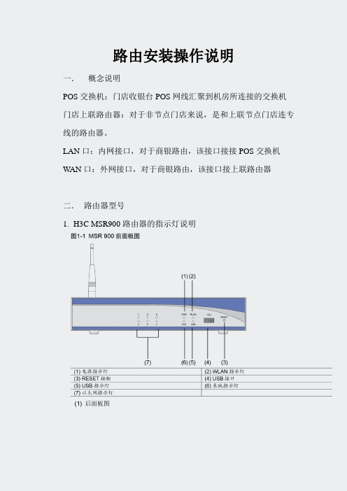
LAN口:内网接口,对于商银路由,该接口接接POS交换机W AN口:外网接口,对于商银路由,该接口接上联路由器二.路由器型号1.H3C MSR900路由器的指示灯说明(1) 后面板图(1) 接地端子(2) 天线(3) 固定交换口2~5 (4) 固定以太网口0~1(5) 配置口(Console)(6) 电源接口2. 面板指示灯及按钮说明MSR 900 路由器的指示灯含及按钮义如下:表1-2MSR 900 路由器前面板指示灯及按钮说明指示灯及按钮正常运行时含义PWR 电源指示灯:灯亮表示电源接通灯灭表示电源没有接通SYS 系统运行状态指示灯:灯绿色快速闪烁表示系统正在启动灯绿色慢速闪烁表示系统正常运行灯黄色快速闪烁表示系统出现故障灯常灭表示系统工作不正常0~5 灯灭表示链路没有连通灯亮表示链路已经连通灯闪烁表示有数据收发USB 接口连接USB 设备RESET 按钮按下RESET 按钮并保持3 秒以上,使设备恢复到出厂缺省设置表1-3MSR 900 路由器后面板指示灯说明WAN LAN指示灯及按钮正常运行时含义接地端子用于连接地线配置口PC 通过串口线与此口连接,对设备进行配置固定以太网口(ETH 0~1) 上行三层以太网接口,用于连接广域网固定交换口(ETH 2~5) 下行二层以太网接口,用于连接计算机或者交换机等设备天线用于传输WLAN 射频信号电源接口直流电源输入,用于连接随设备提供的电源适配器2.CISCO861-K9(上海地区使用)路由器指示灯(根据指示灯判断故障)CISCO861-K9指示灯OK灯亮:代表设备加电成功。
W AN灯亮:代表W AN口插的网线有电,如果不亮则需要检查到上联路由的网线是否插好OK灯WAN灯LAN灯WAN口LAN口LAN口灯亮一个:代表LAN口插的网线有电,一个都不亮则需要检查到POS交换机的网线。
普联技术有限公司路由器 防火墙命令行手册 REV1.0.1说明书

路由器/防火墙命令行手册REV1.0.11910040990声明Copyright © 2021 普联技术有限公司版权所有,保留所有权利未经普联技术有限公司明确书面许可,任何单位或个人不得擅自仿制、复制、誊抄或转译本手册部分或全部内容,且不得以营利为目的进行任何方式(电子、影印、录制等)的传播。
为普联技术有限公司注册商标。
本手册提及的所有商标,由各自所有人拥有。
本手册所提到的产品规格和资讯仅供参考,如有内容更新,恕不另行通知。
除非有特殊约定,本手册仅作为使用指导,所作陈述均不构成任何形式的担保。
目录第1章命令行使用指导 (1)1.1使用命令行 (1)通过Console口进行本地登录 (1)1.2命令行格式约定 (1)基本格式约定 (1)特殊字符 (2)参数格式 (2)第2章用户界面 (3)2.1enable (3)2.2enable password (3)2.3enable secret (4)2.4configure (5)2.5exit (5)2.6show history (6)2.7clear history (6)第3章HTTP和HTTPS配置命令 (7)3.1show ip http configuration (7)3.2show ip http secure-server (7)第4章系统配置命令 (8)4.1reset (8)4.2reboot (8)4.3copy running-config startup-config (9)4.4ping (9)4.5tracert (10)4.6show system-info (10)第5章特征库管理配置命令 (12)5.1update restore sdb-default (12)5.2show version (12)第6章License管理配置命令 (14)6.1license revoke (14)6.2show license (14)6.3show license revoke-ticket (14)第7章业务感知引擎配置命令 (16)7.1sa acceleration (16)7.2no sa acceleration (16)7.3show sa acceleration (17)第1章命令行使用指导1.1 使用命令行用户可以通过Console口进行本地登录路由器或防火墙来使用命令行,本手册命令行以TL-FW6600为例进行说明。
4G路由器操作手册 奥顿A9 RPO

A9-Pro4G多卡聚合路由器(4个4G并发全网通VPN专网5.8G支持自建服务器)产品说明书一、产品基础信息供电电压:DC12V/3A电池容量:9000mah聚合路由器默认IP:192.168.11.1默认密码:admin说明:设备出厂已配置好我司的服务器,用户收到货,插SIM卡、开机后可直接使用,若有大型直播等用网环境,请事先充满电,提前测试好聚合路由器。
二、产品简介多卡聚合路由器是一款支持多路聚合上网的4G路由器,标配适配器DC12V/3A 供电,内置电池容量9000mah,可以使得聚合路由器续航更久,1路WAN口外网输入用于聚合,2路LAN口(LAN1和LAN2)输出到电脑或用网设备,另外还可提供2.4G和5.8G频段的无线网络,可以给更多的设备供网,以满足于用户的更多需求;多卡聚合路由器内置4个4G通信模块,支持同时混插不同运营商的SIM卡,通过云服务器聚合4条上网链路的带宽,不通过云服务器的情况下也可以单卡使用,不过只能跑单卡的流量,提升了移动环境中的上下行网络带宽,减少移动网络信号盲区,提高网络的可用性。
01三、产品接口说明1)天线1:聚合路由器的2.4G和5.8G WiFi共用这两根天线2)天线2:表示SIM卡1的4G天线3)天线3:表示SIM卡2的4G天线4)天线4:表示SIM卡3的4G天线5)天线5:表示SIM卡4的4G天线6)天线6:聚合路由器的2.4G和5.8G WiFi共用这两根天线7)显示屏7:能显示聚合路由器的工作状态等重要信息8)SIM1卡槽:插入该卡槽的4G卡,对应在显示屏上的是卡1位置,正常拨号上网,SIM1卡槽旁边的小孔处会有指示灯常闪9)SIM卡槽2:同SIM1卡槽10)SIM卡槽3:同SIM1卡槽11)SIM卡槽4:同SIM1卡槽12)ON/OFF:聚合路由器的开、关机键13)S:充电指示灯,插上DC12V/3A的适配器,电量没有充满的情况下,该指示灯长亮,充满的情况下,该指示灯灭14)电源:最新款的支持DC12V/3A供电,使用时尽量用原厂配送的适配器,若客户需另更换成自己的电源,供电电压具体咨询销售或原厂技术为准15)REST:聚合路由器重置键,用配送SIM卡的插针插进去,按住约45秒后松开,聚合路由器可恢复至出厂状态16)WAN:外网插入此口聚合路由器可以上网WAN口的网络也可以和4G网络一起聚合17)LAN1:此网口接电脑,可供电脑上网,浏览器输入IP:192.168.11.1,密码:admin,可控制路由器后台,若密码失败:建议更换浏览器继续登录或按住REST键重置路由器18)LAN2:此网口接电脑,可供电脑上网,浏览器输入IP:192.168.11.1,密码:admin,可控制路由器后台,若密码失败:建议更换浏览器继续登录或按住REST键重置路由器四、聚合路由器实操教程1、聚合路由器插入1-4张4G卡,4G卡有芯片一端朝下插入4G卡槽,如下图2、插入4根4G天线和2根天线;(备注:注意区分4G天线和WiFi天线,天线是否带针,4G天线是带针的,WiFi天线不带针)备注:WiFi天线插错会造成4G卡不识别3、按一下聚合路由器的开机键ON/OFF,该指示灯长亮,表示设备已开机,然后等待设备系统启动,完全开机全程约2-3分钟;备注:设备开机会先白屏约10秒钟,然后黑屏约43秒钟,转而出现显示屏的信息,显示屏亮了之后再等约1分钟,显示屏信息完全显示,开机全过程约2-3分钟。
伯尔尼斯顿联网公司产品说明书

A&E*ABC - WVNY*AMCAmerican Heroes Channel Animal PlanetBBC AmericaBBC World NewsBET GospelBET JamsBET SoulBET*BoomerangBravo*Cartoon Network*CBFT - 6 SRCCBMT -6 CBCCBS - WCAXCBS College Sports CCTVCCTV4 (Mandarin) CentricCFCF - 12 CTVChillerCMT MusicCMT*CNBC*CNN InternationalCNN*Comcast SportsNet+ Comedy Central* Cooking ChannelCrime & Investigation CSN PlusC-SPANC-SPAN 2C-SPAN 3Destination America DiscoveryDiscovery Family Discovery LifeDisney Junior*Disney XD*Disney*DIYE!*ESPN 2*+ESPN Classic*+ESPN News*+ESPN U*+ESPN*+Esquire*EVINE LIVEEWTNFamily NetFood NetworkFox - WFFFFox Business News*Fox College Sports Atlantic+ Fox College Sports Central+ Fox College Sports Pacific+ Fox Movie ChannelFox News*Fox Sports 1Fox Sports 2Free Speech TV Freeform*FuseFusionFXFXXFYI*GACGame Show NetworkGolf Channel*HallmarkHallmark Movies & Mysteries Headline NewsHGTVHistory en Español History*Home Shopping Network IFCInspiration Network Investigation Discovery 9646619478924313313613988155977011133421740113212115138323811311127837285327181920908189191715453935829303126285623104116749471421431446546413912249861196135941307544521811127319376226710891SBSS+SSS+S+S+S+SS+SSBBBS+BBS+BS+S+SSSSSSS+S+SBBBS+SSS+S+SSS+SSSS+S+SS+BSSSBS+S+S+S+SSSSBSS+S+SSS+SSS+SSSSS+SBSSS296204266278292243288297270203242317232238211227283272218219220290281289271254253293258229228274209247265246241239249319261235294330275244252262212273276267291Lifetime*Lifetime Movie*Lifetime Real WomenLOGOMeTVMilitary History ChannelMLB+MoviePlexMovies! TV NetworkMSNBC*MTV*MTV 2MTV ClassicMTV LiveMTV TresMTV UNat GeoNat Geo WildNBC - WPTZ*NBC Sports Extra Time 1NBC Sports NetworkNBC -WNNENESN Plus+NESN+NFL NetworkNick Jr.*Nick MusicNick TooNickelodeon*NicktoonsNortheast Sports NetworkOutdoor ChannelOvationOWNOxygen*PBS - WCFEQVCQVC PlusRETNScience ChannelSEC AltSEC Network*Spike TVSportsman Channel*Sprout*SundanceSYFY*TBN - Trinity BroadcastingTBS*Teen NickTennis Channel*The CWThe Weather ChannelTLCTNT*Travel ChanneltruTV*Turner Classic Movies*TV LandTVG2Universal HDUSA*UVMTVVCAMVelocityVermont PBSVermont PBS CreateVermont PBS KidsVermont PBS+VH1*Viceland*VTTVWEMountiain Lake PBSWorldview10110210911832519225685303143313113722113414077485337378336361471511351525715430245988299107211687352149551456469368107511534030524806079696315014137050300153716308306307349559100311310SSSS+BS+SS+BSSSS+SS+S+SSBS+SBSSS+SS+S+SS+BS+SSSBBBBS+S+S+SS+S+S+SSBS+S+BBSSSSSSS+S+SBBSBBBBSS+BSBB201202225689214233277248205337237208356236347257245298282299210207321287353351255695268251240324280260279269263370250313215371206307234295259284B - Basic PackageS - Standard Package(Includes All Basic Channels)S+ - Standard Plus(Includes All Basic & Standard Channels)Network SD HD Network SD HDEffective February 2017*Subject to changeChannel Guide5 Star MaxAction MaxCinemax*Cinemax SpanishFlixHBO*HBO 2HBO ComedyHBO FamilyHBO LatinoHBO SignatureHBO ZoneIndiePLEXMore MaxMovie MaxOuter MaxRetroPlexShowtimeShowtime 2Showtime BeyondShowtime ExtremeShowtime Family ZoneShowtime NextShowtime ShowcaseShowtime WomenSTARZSTARZ CinemaSTARZ ComedySTARZ EdgeSTARZ ENCORESTARZ ENCORE ActionSTARZ ENCORE BlackSTARZ ENCORE ClassicSTARZ ENCORE FamilySTARZ ENCORE SuspenseSTARZ ENCORE WesternsSTARZ in BlackSTARZ Kids & FamilyThe Movie ChannelThriller MaxTMC Extra640638636643694621622625624627623626668637642641669600601604603606605602607662666667663679680684683682678681664665608639609644628610611670674673686687688671618Premium SD HD‘70s‘80s‘90sAdult AlternativeAlternativeBluesClassic CountryClassic MasterpiecesClassic RockContemporary ChristianCountry HitsDance/EDMEasy ListeningGospelHip-Hop and R&BHip-Hop ClassicsHit ListIndieJazzKidz Only!Light ClassicalLove SongsMetalMexicanaMusica UrbanaParty FavoritesPop CountryPop HitsPop LatinoPop RhythmicR&B ClassicsR&B SoulRapReggaeRockRock HitsRomancesSingers & SwingSmooth JazzSoft RockSolid Gold OldiesSounds of the SeasonsSoundscapesStage & ScreenTeen MCThrowback JamsToday’s CountryToddler TunesTropicalesY2K729728727716715746734749718735733703748711705707701704745724750720714738737722731721736702709710706712713717740747744719730741743742723708732725739726Music Choice SDMediaset Italia♦ (Italian)MLB Strike Zone+♦NFL Redzone♦SBTN♦ (Vietnamese)TV 5♦ (French)405146148403404346348424Add-Ons SD HDAll channel lineups are subject to change. HD channels require an HD set top box.* Online/Mobile Content Available! Stream your favorite shows. Visit our website and watch with our TV Everywhere service.+ Channel also included with sports package.♦ Additional fee required.Stream over 50 channels including news, sportsand entertainment sent straight to your smart-phone, tablet, or laptop.Access to the channels is based on the cablepackage that the customer is subscribed to. Toadd greater channel access, please call customerservice.Visit/tv/tv-everywhereTV EverywhereInstant access to hundreds movies and shows OnDemand. Catch up on shows you’ve missed or tryout a new series anytime with Free On Demandfrom NBC, ABC, CBS, FOX, and more.Subscribe to a Premium Channel? You haveaccess to shows and movies free On Demand.Visit/tv/video-on-demandVideo on Demand。
LTE网络重选及切换全参数详解

LTE网络重选及切换参数详解小区选择小区选择发生在PLMN选择之后,它的目的是使UE在开机后可以尽快选择一个信道质量满足条件的小区进行驻留。
●读取系统信息(例如,驻留、接入和重选相关信息,位置区域信息等);●读取寻呼信息;●发起连接建立过程。
一般来说,UE开机后会首先进行PLMN选择,然后进行小区选择/重选、位置登记等。
由于PLMN选择和位置登记主要是NAS的功能,下面将介绍小区选择过程。
▊PLMN IDPublic Land Mobile Network ID,公共陆地移动网络ID, 由政府或它所批准的经营者,为公众提供陆地移动通信业务目的而建立和经营的网络标识。
PLMN = MCC + MNC,例如中国移动的PLMN为46000,中国联通的PLMN为46001。
▊MCCMobile Country Code 移动设备国家代码三个数字,如中国为460。
▊MNC移动设备网络代码(Mobile Network Code,MNC)是与移动设备国家代码(Mobile Country Code,MCC)(也称为“MCC / MNC”)相结合,以用来表示唯一一个的移动设备的网络运营商。
由所在国家分配,通常2~3数字组成。
小区选择类型:不同场景:初始小区选择、存储信息的小区选择。
不同时机:UE开机、从RRC_CONNECTED返回到RRC_IDLE模式、重新进入服务区(1) 初始小区选择这种情况下,UE没有储存任何先验信息可以帮助其辨识具体的TD-LTE系统频率,因此,UE需要根据其自身能力扫描所有的TD-LTE频带,以便找到一个合适的小区进行驻留。
在每一个频率上,UE只需用搜索信道质量最好的小区,一旦一个合适的小区出现,UE会选择它并进行驻留。
空闲状态下的UE需要完成的过程包括公共陆地移动网络(PLMN)选择、小区选择/重选、位置登记等。
一旦完成驻留,UE可以读取系统信息(如驻留、接入和重选相关信息、位置区域信息等),读取寻呼信息,发起连接建立过程。
思科路由器配置命令大全

思科路由器常用配置命令一览表:1、Exec commands:<1-99> 恢复一个会话bfe 手工应急模式设置clear 复位功能clock 管理系统时钟configure 进入设置模式connect 打开一个终端copy 从tftp服务器拷贝设置文件或把设置文件拷贝到tftp服务器上debug 调试功能disable 退出优先命令状态disconnect 断开一个网络连接enable 进入优先命令状态erase 擦除快闪内存exit 退出exce模式help 交互帮助系统的描述lat 打开一个本地传输连接lock 锁定终端login 以一个用户名登录logout 退出终端mbranch 向树形下端分支跟踪多路由广播mrbranch 向树形上端分支跟踪反向多路由广播name-connection 给一个存在的网络连接命名no 关闭调试功能pad 打开X.29 PAD连接ping 发送回显信息ppp 开始点到点的连接协议reload 停机并执行冷启动resume 恢复一个活动的网络连接rlogin 打开远程注册连接rsh 执行一个远端命令send 发送信息到另外的终端行setup 运行setup命令show 显示正在运行系统信息slip 开始SLIP协议start-chat 在命令行上执行对话描述systat 显示终端行的信息telnet 远程登录terminal 终端行参数test 测试子系统内存和端口tn3270 打开一个tin3270连接trace 跟踪路由到目的地undebug 退出调试功能verify 验证检查闪烁文件的总数where 显示活动的连接which-route 执行OSI路由表查找并显示结果write 把正在运行的设置写入内存、网络、或终端x3 在PAD上设置X.3参数xremote 进入xremote模式2、#show ?access-expression 显示访问控制表达式access-lists 显示访问控制表apollo Apollo 网络信息appletalk Apple Talk 信息arap 显示Appletalk 远端通道统计arp 地址解析协议表async 访问路由接口的终端行上的信息bridge 前向网络数据库buffers 缓冲池统计clns CLNS网络信息clock 显示系统时钟cmns 连接模式网络服务信息compress 显示压缩状态configuration 非易失性内存的内容controllers 端口控制状态debugging 调试选项状态decnet DEC网络信息dialer 拨号参数和统计dnsix 显示Dnsix/DMPP信息entry 排队终端入口extended 扩展端口信息flash 系统闪烁信息flh-log 闪烁装载帮助日志缓冲区frame-relay 帧中继信息history 显示对话层历史命令hosts IP域名,查找方式,名字服务,主机表interfaces 端口状态和设置ip IP信息ipx Novell IPX信息isis IS-IS路由信息keymap 终端键盘映射lat DEC LAT信息line 终端行信息llc2 IBM LLC2 环路信息lnm IBM 局网管理local-ack 本地认知虚环路memory 内存统计netbios-cache NetBios命名缓冲存贮器内存node 显示已知LAT节点ntp 网络时间协议processes 活动进程统计protocols 活动网络路由协议queue 显示队列内容queueing 显示队列设置registry 功能注册信息rhosts 远程主机文件rif RIF存贮器入口route-map 路由器信息sdlle 显示sdlc-llc2转换信息services 已知LAT服务sessions 远程连接信息smds SMDS信息source-bridge 源网桥参数和统计spanning-tree 跨越树形拓朴stacks 进程堆栈应用standby 热支持协议信息stun STUN状态和设置subsystem 显示子系统tcp TCP连接状态terminal 显示终端设置tn3270 TN3270 设置translate 协议转换信息ttycap 终端容易表users 显示终端行的信息version 系统硬、软件状态vines VINES信息whoami 当前终端行信息x25 X.25信息xns XNS信息xermote Xremote统计3、#config ?Memory 从非易失性内存设置Network 从TFTP网络主机设置Overwrite-network 从TFTP网络主机设置覆盖非易失性内存Terminal 从终端设置4、Configure commads:Access-list 增加一个访问控制域Apollo Apollo全局设置命令appletalk Appletalk 全局设置命令arap Appletalk远程进出协议arp 设置一个静态ARP入口async-bootp 修改系统启动参数autonomous-system 本地所拥有的特殊自治系统成员banner 定义注册显示信息boot 修改系统启动时参数bridge 透明网桥buffers 调整系统缓冲池参数busy-message 定义当连接主机失败时显示信息chat-script 定义一个调制解调器对话文本clns 全局CLNS设置子命令clock 设置时间时钟config-register 定义设置寄存器decnet 全局DEC网络设置子命令default-value 缺省字符位值dialer-list 创建一个拨号清单入口dnsix-nat 为审计提供DMDM服务enable 修改优先命令口令end 从设置模式退出exit 从设置模式退出frame-relay 全局帧中继设置命令help 交互帮助系统的描述hostname 设置系统网络名iterface 选择设置的端口ip 全局地址设置子命令ipx Novell/IPX全局设置命令keymap 定义一个新的键盘映射lat DEC本地传输协议line 设置终端行lnm IBM局网管理locaddr-priority-list 在LU地址上建立优先队列logging 修改注册(设备)信息login-string 定义主机指定的注册字符串map-class 设置静态表类map-list 设置静态表清单menu 定义用户接口菜单mop 设置DEC MOP服务器netbios NETBIOS通道控制过滤no 否定一个命令或改为缺省设置ntp 设置NTPpriority-list 建立特权列表prompt 设置系统提示符queue-list 建立常规队列列表rcmd 远程命令设置命令rcp-enable 打开Rep服务rif 源路由进程router-map 建立路由表或进入路由表命令模式router 打开一个路由进程rsh-enable 打开一个RSH服务sap-priority-list 在SAP或MAC地址上建立一个优先队列service 修改网络基本服务snmp-server 修改SNMP参数state-machine 定义一个TCP分配状态的机器stun STUN全局设置命令tacacs-server 修改TACACS队列参数terminal-queue 终端队列命令tftp-server 为网络装载请求提供TFTP服务tn3270 tn3270设置命令translate 解释全局设置命令username 建立一个用户名及其权限vines VINES全局设置命令x25 X.25 的第三级x29 X.29 命令xns XNS 全局设置命令xremote 设置Xremote5、(config)#ipGlobal IP configuration subcommands:Accounting-list 选择保存IP记帐信息的主机Accounting-threshold 设置记帐入口的最大数accounting-transits 设置通过入口的最大数alias TCP端口的IP地址取别名as-path BGP自治系统路径过滤cache-invalidate-delay 延迟IP路由存贮池的无效classless 跟随无类前向路由规则default-network 标志网络作为缺省网关候选default-gateway 指定缺省网(如果没有路由IP)domain-list 完成无资格主机的域名domain-lookup 打开IP域名服务系统主机转换domain-name 定义缺省域名forward-protocol 控制前向的、物理的、直接的IP广播host 为IP主机表增加一个入口host-routing 打开基于主机的路由(代理ARP和再定向)hp-host 打开HP代理探测服务mobile-host 移动主机数据库multicast-routing 打开前向IPname-server 指定所用名字服务器的地址ospf-name-lookup 把OSPF路由作为DNS名显示pim PIM 全局命令route 建立静态路由routing 打开IP路由security 指定系统安全信息source-route 根据源路由头的选择处理包subnet-zero 允许子网0子网tcp 全局TCP参数1. switch配置命令(1)模式转换命令用户模式----特权模式,使用命令"enable"特权模式----全局配置模式,使用命令"config t"全局配置模式----接口模式,使用命令"interface+接口类型+接口号" 全局配置模式----线控模式,使用命令"line+接口类型+接口号"注:用户模式:查看初始化的信息.特权模式:查看所有信息、调试、保存配置信息全局模式:配置所有信息、针对整个路由器或交换机的所有接口接口模式:针对某一个接口的配置线控模式:对路由器进行控制的接口配置(2)配置命令show running config 显示所有的配置show versin 显示版本号和寄存器值shut down 关闭接口no shutdown 打开接口ip add +ip地址配置IP地址secondary+IP地址为接口配置第二个IP地址show interface+接口类型+接口号查看接口管理性show controllers interface 查看接口是否有DCE电缆show history 查看历史记录show terminal 查看终端记录大小hostname+主机名配置路由器或交换机的标识config memory 修改保存在NVRAM中的启动配置exec timeout 0 0 设置控制台会话超时为0service password-encryptin 手工加密所有密码enable password +密码配置明文密码ena sec +密码配置密文密码line vty 0 4/15 进入telnet接口password +密码配置telnet密码line aux 0 进入AUX接口password +密码配置密码line con 0 进入CON接口password +密码配置密码bandwidth+数字配置带宽no ip address 删除已配置的IP地址show startup config 查看NVRAM中的配置信息copy run-config atartup config 保存信息到NVRAMwrite 保存信息到NVRAMerase startup-config 清除NVRAM中的配置信息show ip interface brief 查看接口的谪要信息banner motd # +信息+ # 配置路由器或交换机的描素信息description+信息配置接口听描素信息vlan database 进入VLAN数据库模式vlan +vlan号+ 名称创建VLANswitchport access vlan +vlan号为VLAN为配接口interface vlan +vlan号进入VLAN接口模式ip add +ip地址为VLAN配置管理IP地址vtp+service/tracsparent/client 配置SW的VTP工作模式vtp +domain+域名配置SW的VTP域名vtp +password +密码配置SW的密码switchport mode trunk 启用中继no vlan +vlan号删除VLANshow spamming-tree vlan +vlan号查看VLA怕生成树议2. 路由器配置命令ip route+非直连网段+子网掩码+下一跳地址配置静态/默认路由show ip route 查看路由表show protocols 显示出所有的被动路由协议和接口上哪些协议被设置show ip protocols 显示了被配置在路由器上的路由选择协议,同时给出了在路由选择协议中使用的定时器等信息router rip 激活RIP协议network +直连网段发布直连网段interface lookback 0 激活逻辑接口passive-interface +接口类型+接口号配置接口为被动模式debug ip +协议动态查看路由更新信息undebug all 关闭所有DEBUG信息router eigrp +as号激活EIGRP路由协议network +网段+子网掩码发布直连网段show ip eigrp neighbors 查看邻居表show ip eigrp topology 查看拓扑表show ip eigrp traffic 查看发送包数量router ospf +process-ID 激活OSPF协议network+直连网段+area+区域号发布直连网段show ip ospf 显示OSPF的进程号和ROUTER-IDencapsulation+封装格式更改封装格式no ip admain-lookup 关闭路由器的域名查找ip routing 在三层交换机上启用路由功能show user 查看SW的在线用户clear line +线路号清除线路3. 三层交换机配置命令配置一组二层端口configure terminal 进入配置状态nterface range {port-range} 进入组配置状态配置三层端口configure terminal 进入配置状态interface {{fastethernet | gigabitethernet} interface-id} | {vlan vlan-id} | {port- channel port-channel-number} 进入端口配置状态no switchport 把物理端口变成三层口ip address ip_address subnet_mask 配置IP地址和掩码no shutdown 激活端口例:Switch(config)# interface gigabitethernet0/2Switch(config-if)# no switchportSwitch(config-if)# ip address 192.20.135.21 255.255.255.0Switch(config-if)# no shutdown配置VLANconfigure terminal 进入配置状态vlan vlan-id 输入一个VLAN号, 然后进入vlan配态,可以输入一个新的VLAN 号或旧的来进行修改。
NETGEAR WAC104 双频WiFi点访网络接入点用户指南说明书
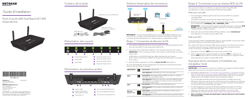
NETGEAR, Inc.350 East Plumeria Drive San Jose, CA 95134, USA (Etats-Unis)© NETGEAR, Inc., NETGEAR et le logo NETGEAR sont des marques commerciales de NETGEAR, Inc. Toutes les marques commerciales autres que NETGEAR sont utilisées à des fins de référence uniquement.Juillet 2021NETGEAR INTERNATIONAL LTD Floor 1, Building 3,University Technology Centre Curraheen Road, Cork, T12EF21, IrlandeGuide d’installationPoint d'accès Wifi Dual Band AC1200Modèle WAC1045Contenu de la boîte Présentation des voyantsAu cours de l’installation et de la configuration, les voyants du point d’accès peuvent s’allumer avec les couleurs suivantes :AlimentationVert continu . Le PA est prêt.Vert clignotant . Le PA démarre ou met à jour le firmware.WPSVert continu . Wi-Fi Protected Setup (WPS) est prêt pour utilisation. Par défaut, le voyant WPS est éteint.Vert clignotant . Quelqu’un a appuyé sur le bouton WPS du PA afin de permettre à son ordinateur ou appareil mobile compatible WiFi de rejoindre le réseau WiFi.WiFiVert continu . Une ou plusieurs radios WiFi fonctionnent.Vert clignotant . Une ou plusieurs radios WiFi envoient ou reçoivent du trafic.Réseauxlocaux 1 à 4Vert continu . Le port de réseau local détecte une liaison avec un appareil du réseau local.Vert clignotant . Le port de réseau local transmet ou reçoit des données.51. Connectez le câble Ethernet fourni avec le produit à l'un des ports Ethernet du PA.Vous pouvez utiliser l'un des quatre ports LAN du PA.2. Connectez l'autre extrémité du câble à un port de réseau local de votre routeur.REMARQUE : Ne connectez pas le PA à votre modem. Le PA doit être connecté à votre routeur.Le PA utilise un client DHCP activé par défaut. Presque tous les routeursfonctionnent comme serveurs DHCP , ce qui permet au PA de recevoir une adresse IP du routeur.3. Allumez le PA en appuyant sur le bouton Power On/Off (Alimentation).Étape 1. Connectez et allumez le PASchéma d’exemples de connexions IMPORTANT : Le point d’accès (PA) fournit une connectivité WiFi et LAN mais c'est un pont et non un routeur. Connectez le PA à un routeur connecté à un modem. Ne connectez pas le PA directement à un modem tel qu'un modem DSL ou câble.Etape 2. Connectez-vous au réseau WiFi du PAVous pouvez connecter un ordinateur ou appareil mobile compatible WiFi manuellement ou utiliser la méthode Wi-Fi Protected Setup (WPS).Méthode manuelle1. Ouvrez le logiciel utilitaire gestionnaire de connexions WiFi d’un appareilcompatible WiFi.Cet utilitaire recherche l'ensemble des réseaux WiFi disponibles.2. Recherchez et sélectionnez l’un des noms de réseau WiFi par défaut du PA (SSID),qui correspondent à NETGEAR_11N et NETGEAR_11AC .REMARQUE : Si vous ne pouvez pas trouver les SSID, appuyez sur le bouton WiFi On/Off (activation/désactivation du WiFi), patientez une minute et regardez si l’utilitaire affiche un SSID ou les deux.3. Saisissez la phrase d’authentification WiFi par défaut, à savoir sharedsecret .Votre appareil se connecte au réseau WiFi du PA.Méthode WPSSi votre appareil mobile compatible WiFi prend en charge le WPS, vous pouvez utiliser cette technologie pour rejoindre le réseau WiFi du AP .Pour obtenir de l'aide sur le bouton WPS de votre appareil, consultez les instructions ou l'aide en ligne fournies avec l'appareil concerné. Certains équipements plus anciens ne sont pas compatibles avec la fonction WPS.1. Appuyez sur le bouton WPS situé sur le panneau arrière du PA.2. Dans un délai de deux minutes, appuyez sur le bouton WPS ou cliquez sur lebouton WPS physique affiché sur l'écran de votre ordinateur ou appareil mobile.Votre appareil se connecte au réseau WiFi du PA.1Bouton WPS 2Bouton d'activation/désactivation du Wifi 3Ports LAN 1-44Bouton Reset (Réinitialisation)5Bouton On/Off (Alimentation)6Connecteur d'alimentation CCPrésentation du panneau arrière1Voyant d’alimentation 2Voyant WPS 3Voyant WiFi4Voyant de réseau local 15Voyant de réseau local 26Voyant de réseau local 37Voyant de réseau local 41234567A propos de la connexion à l’interface sur navigateur localIMPORTANT : Les étapes de connexion à l’interface du navigateur local de votre PA dépendent de la version du firmware qu’exécute votre PA.•Les étapes indiquées Étape 3. Connectez-vous à l’interface sur navigateur local et Etape 4. Recherchez un nouveau firmware s’appliquent uniquement si vous mettez à jour la version du firmware de votre PA avec la version 1.0.4.15 ou une version ultérieure, puis réinitialisez le PA avec ses paramètres par défaut.Si vous avez déjà réinitialisé le PA avec les paramètres par défaut après avoireffectué la mise à jour avec la version 1.0.4.15, et que vous mettez à jour le PA avec une version ultérieure à la version 1.0.4.15, il n’est pas nécessaire de réinitialiser à nouveau le PA avec ses paramètres par défaut.•Si votre PA exécute une version de firmware antérieure à la version 1.0.4.15 et que vous n’effectuez pas la mise à jour avec la version 1.0.4.15 ou une version ultérieure, reportez-vous à l’ancien guide d’installation, que vous pouvez télécharger en visitant le site https:///support/download/.•Nous conseillons vivement de télécharger le dernier firmware et de l’installer dès que possible.Visitez /support pour obtenir des réponses à vos questions et accéder aux derniers téléchargements.Vous pouvez également consulter notre communauté NETGEAR pour obtenir de bons conseils sur .Support et communautéPour les informations à propos de la conformité réglementaire, y compris la Déclaration de conformité pour l'UE, rendez-vous sur https:///about/regulatory/.Avant de brancher l’alimentation, reportez-vous au document de conformité légale.N’utilisez pas ce périphérique à l’extérieur.Applicable aux appareils 6 GHz uniquement : utilisez cet appareil en intérieur uniquement. L'utilisation de périphériques 6 GHz est interdite sur les plateformes pétrolières, les voitures, les trains, les bateaux et les aéronefs, à une exception : l'utilisation de ce périphérique est autorisée sur les grands avions volant à plus de 10 000 pieds d’élévation. L'utilisation d'émetteurs sur la bande 5,925 - 7,125 GHz est interdite pour le contrôle de systèmes d'aéronef sans pilote ou la communication avec ces systèmes.Règlementation et aspects juridiquesCes étapes s’appliquent uniquement si vous avez mis à jour la version du firmware de votre PA avec la version 1.0.4.15 ou une version ultérieure, puis réinitialisé le PA avec ses paramètres par défaut.Avant de commencer à utiliser votre PA, nous vous recommandons d’utiliser la fonction de mise à jour automatique du PA pour rechercher un nouveau firmware.1. Ouvrez un navigateur Web sur un appareil compatible WiFi disposant d’uneconnexion WiFi au PA (voir Etape 2. Connectez-vous au réseau WiFi du PA ) et saisissez ou dans le champ d’adresse.Une fenêtre de connexion s'affiche.2. Saisissez le nom d'utilisateur et le mot de passe du PA.Le nom d'utilisateur est admin . Le mot de passe est celui que vous avez indiqué sur la page de configuration initiale lors de votre première connexion à l’interface sur navigateur local (voir Étape 3. Connectez-vous à l’interface sur navigateur local ). Le nom d'utilisateur et le mot de passe sont sensibles à la casse.L'écran d'accueil s'affiche.3. Sélectionnez Administration > Firmware Update (Administration > Mise à jourdu micrologiciel).La page Mise à jour du firmware s'affiche.4. Cliquez sur le bouton Check (Vérifier).le PA détecte un nouveau firmware ; en cas de disponibilité, il affiche un message vous demandant si vous voulez le télécharger et l’installer.5. Pour télécharger et installer le nouveau firmware, cliquez sur le bouton Yes (Oui).Le PA localise le firmware, le télécharge et démarre la mise à jour.Une barre de progression indique la progression du chargement du firmware. La procédure de chargement du firmware prend plusieurs minutes. Une fois le chargement terminé, votre PA redémarre.AVERTISSEMENT : Pour éviter tout risque de corruption du micrologiciel (firmware), n'interrompez pas la mise à jour. Par exemple, ne fermez pas le navigateur, ne cliquez pas sur un lien et ne chargez pas de nouvelle page. N'éteignez pas le PA. Patientez jusqu’à ce que le PA termine le chargement dunouveau firmware et redémarre, et que le voyant d’alimentation cesse de clignoter et reste allumé en vert continu.6. Reconnectez-vous à l’interface sur navigateur local.L'écran d'accueil s'affiche. La version du firmware est indiquée dans le champ Firmware Version (version du firmware) du panneau d’informations du PA.Etape 4. Recherchez un nouveau firmwareCes étapes s’appliquent uniquement si vous avez mis à jour la version du firmware de votre PA avec la version 1.0.4.15 ou une version ultérieure, puis réinitialisé le PA avec ses paramètres par défaut.1. Ouvrez un navigateur Web sur un appareil compatible WiFi disposant d’uneconnexion WiFi au PA (voir Etape 2. Connectez-vous au réseau WiFi du PA ) et saisissez ou dans le champ d’adresse.Ces URL sont les mêmes que l’adresse IP 192.168.0.100. Une fenêtre de connexion s'affiche.2. Saisissez le nom d'utilisateur et le mot de passe du PA.Le nom d'utilisateur est admin . Le mot de passe par défaut est password . Le nom d'utilisateur et le mot de passe sont sensibles à la casse.La page de configuration initiale s'affiche. Cette page s’affiche uniquement lors de votre première connexion à l’interface utilisateur sur navigateur local.3. Sur la page de configuration initiale, procédez comme suit :• Définissez un nouveau mot de passe pour l’administrateur.•Activez la récupération du mot de passe et définissez des questions desécurité. Bien que cette opération soit facultative, nous vous recommandons d’activer la récupération du mot de passe.•Pour une meilleure sécurité, vous pouvez également définir de nouveaux noms de réseau WiFi (SSID) pour le réseau WiFi dans les bandes radio 2,4 GHz et 5 GHz et de nouvelles phrases d’authentification WiFi.Nous vous recommandons de laisser le PA obtenir son adresse IP du routeur de votre réseau (il s’agit du paramètre par défaut). Toutefois, si vous voulez utiliser une adresse IP statique pour le PA, vous pouvez le faire.4. Cliquez sur le bouton Apply (Appliquer).Les paramètres sont enregistrés.5. Si vous définissez un nouveau SSID et une phrase d’authentification, reconnectez-vous au PA à l’aide du nouveau SSID et de la phrase d’authentification.6. Reconnectez-vous à l’interface utilisateur sur navigateur local à l’aide de votrenouveau mot de passe.Vous pouvez à présent contrôler et gérer le PA.Étape 3. Connectez-vous à l’interface sur navigateur localConseils de dépannageLe tableau suivant fournit des conseils pour résoudre des problèmes simples que vous pouvez rencontrer. pour plus d'informations sur le dépannage, reportez-vous au chapitre Dépannage du manuel de l'utilisateur.ProblèmeCauseSolution possibleVous ne pouvez pas vousconnecter par WiFi au PA.Le voyant WiFi est éteint, ce qui indique que les radios WiFi sont désactivées.Vérifiez que les radios sont sous tension en appuyant sur le bouton WiFi On/Off (Marche/arrêt du WiFi).Vous utilisez peut-être de mauvais identifiants WiFi.Si vous n’avez pas modifié les SSID pardéfaut et la phrase d’authentification WiFi par défaut, vérifiez que vous vous connectez à NETGEAR_11N ou NETGEAR_11AC et que vous utilisez sharedsecret comme phrase d’authentification WiFi.Vous êtes trop loin du PA.Rapprochez-vous du PA et réessayez.Vous ne pouvez pas connecter plus de cinqclients WiFi au PA.Le PA ne trouve pas de serveur DHCP sur votre réseau.Vérifiez que l’un des ports de réseau local du PA est connecté à un routeur de votre réseau, afin que le PA puisse récupérer une adresse DHCP .Vous ne pouvez pas accéder à Internet.Plusieurs causes possibles.• Vérifiez que l’un des ports de réseau local du PA est connecté à un routeur de votre réseau.• Vérifiez que le routeur est connecté à votre modem.• Vérifiez que votre modem est connecté à la prise Internet.• Assurez-vous que votre fournisseur d'accès à Internet (FAI) ne connaisse pas de panne.Vous ne pouvez pas accéder au navigateur local après avoir mis à jour le firmware avec la version 1.0.4.15.Le nouveau firmware ne s’est pas installé complètement.1. Réinitialisez le PA avec ses paramètres par défaut en appuyant sur le bouton encastré Reset (Réinitialisation) sur le panneau arrière pendant au moins 10 secondes.2. Attendez que le voyant d’alimentation soit vert continu.3. Connectez-vous à l’interface sur navigateur local (voir Étape 3. Connectez-vous à l’interface sur navigateur local ).4. Reconfigurez le PA.Vous utilisez peut-être de mauvais identifiantsd’administrateur.Si vous n’avez pas encore modifié le mot de passe par défaut, saisissez password . Lenom d'utilisateur est admin . (Vous ne pouvez pas modifier le nom d’utilisateur.) Le nomd'utilisateur et le mot de passe sont sensibles à la casse.。
WIREMOLD Resource RFB Series 地板盒说明说明书

Recessed Floor Boxes for Concrete & Wood Floors Resource RFB® Series of Floor Boxes are versatile recessedactivation solutions that provide power, communication and/oraudio/video services to open space areas, or directly to workstations.Resource RFB Series Floor Boxes are available in two- to six-gangmodels with a variety of aesthetic cover options including colors andprofiles available.Resource RFB Series Floor Boxes have many applications, includingschools, financial institutions, commercial office buildings,hospitality and residences.F E A T U R E S&B E N E F I T Sn RFB6 & RFB6E have independent wiring compartments that allow capacity for up to six duplex receptacles and/or communication services. Reduces overall cost by providing for most cabling requirements. n The RFB4 has three versions for various applications. A cast iron version to meet on grade requirements, a steel version to reduce installation cost on above grade floors, and a shallow steel version that provides flexibility with varying concrete depths. n Fully adjustable before and afterthe concrete pour. Labor savings by adapting to various pour depths and conditions.n Range of conduit sizes. Allows for most conduit schemes, even feed through capability, which saves time and money during installation. KOs range from 1/2" to 2" trade size.n T riple service boxes. Accommodate power, communication and/or audio/video devices which reduces the need for multiple boxes.n A ccepts round Evolution™ Series Covers. RFB4E Series Floor Box acceptthe round 6" Evolution™ Series Coverswhile RFB6E Series Floor Box acceptsthe round 8" Evolution™ Series Coversincreasing the ability to match aesthetics throughout the building.n RFB2 & RFB4 shallow versions allowpass-around tunneling. Flexibility indesign to have adjacent compartmentswired together.n Redesigned FloorPort ActivationCovers. Provides TopGuard protectionfrom water, dirt and debris plusadded strength and durability. Nowavailable in brushed aluminum and fivedecorative powder coat finishes: Black,Brass, Nickel, Gray and Bronze.n Wide variety of mounting brackets.Can adapt to most power andcommunication needs. Reduces overalllife cycle cost.n RFB4E and RFB6E Series Floor Boxesavailable for bare concrete andterrazzo floors. By using RFB4E-CTRor RFB6E-CTR Rings (sold separately)these boxes can be installed into bareconcrete or terrazzo floors with a clean,aesthetic finish.n Datacom connectivity options.Accepts industry standard andproprietary devices from a wide rangeof manufacturers to provide a seamlessand aesthetically pleasing interfacefor voice, data, audio, and videoapplications at the point-of-use. A wideselection of data and adapter optionsare available for use with Ortronics®TracJack™ and Series II devices.n2" Conduit Hub. By using 2HUB with theRFB4E Series Floor Box (sold separately)a greater capacity of pre-terminatedcables can be brought in the a shallowerbox. Increasing the functionality andreducing concrete pours.n I nstalls in both concrete and woodfloors. Provides the first recessed woodfloor box for both commercial andresidential applications. Available forRFB2, RFB6 and RFB6E SeriesFloor Boxes.n L ightweight “slab-on-grade” version.Special fusion-bonded epoxy corrosionresistant paint finish allows for slab-on-grade use without the weight of castiron material. Available in RFB2, RFB4E,RFB6 and RFB6E Series Floor Boxes.n A ccepts Floorport™ Activation Covers.Allows a consistent aesthetic finishfor the RFB2, RFB4 & RFB6 SeriesRecessed Floor Boxes.n B uy America Act/NAFTA versions.FloorPort Service Fittings are nowavailable in versions that meet theBuy America Act/NAFTA requirements.n UL Listed to U.S. and Canadian safetystandards for tile, terrazzo, carpet andwood floors.Protection from water,dirt, and debris.RFB4 Series Floor Box with thenew FloorPort Activation Cover.。
ReCON Shop Floor_软体操作手册_V04.00.000

ReCON Shop Floor
子視窗(連線機台)功能介紹
功能操作區
圖六、子視窗(連線機台) 主要可分為三個區域: 一. 狀態區:主要顯示四種狀態資訊:連線燈號、警報/警告燈號、連線狀態、機台狀態。
3 子視窗(連線機台)功能介紹 ................................................................................................... 9
3.1 操作畫面 ..................................................................................................................................9 3.2 連線........................................................................................................................................10 3.3 斷線........................................................................................................................................10 3.4 簡訊編輯 ................................................................................................................................ 11 3.5 檔案傳輸 ................................................................................................................................12
floor acquisition multiple access -回复

floor acquisition multiple access -回复什么是楼层获取多址(Floor Acquisition Multiple Access)?如何工作?为什么它是一种有效的多址技术?如何应用于无线通信系统?我将逐步回答这些问题。
第一步,我们来了解什么是楼层获取多址(Floor Acquisition Multiple Access)。
楼层获取多址是一种用于多址通信系统的技术,允许多个终端设备同时传输数据,以增加系统的容量。
它通过将系统的时间或频率资源划分成稍微不同的子资源,由终端设备动态选择并获取这些子资源来实现同时通信。
接下来,我们来了解楼层获取多址的工作原理。
楼层获取多址基于终端设备之间的协作,其中每个终端设备相互感知和调整自己的传输功率和频率。
当终端设备想要进行数据传输时,它首先会感知信道的可用性。
如果信道空闲,终端设备会选择一个可用的子资源,并发送请求以获取该子资源的使用权限(也称为”楼层“)。
其他终端设备也会监听信道,并避免在同一子资源上进行传输。
一旦终端设备获得楼层的许可,它将进行数据传输,直到传输完成或释放楼层。
为什么楼层获取多址是一种有效的多址技术呢?首先,楼层获取多址具有高容量的特点。
由于终端设备可以同时使用不同的子资源,系统的容量可以极大地增加。
此外,楼层获取多址还具有较低的延迟。
终端设备只需要等待可用的子资源,并且不需要等待固定的时间间隔。
这意味着终端设备可以更快地进行数据传输,从而降低了传输延迟。
现在,我们来看看楼层获取多址如何应用于无线通信系统。
在无线通信系统中,多个终端设备需要共享有限的频率和时间资源。
传统的多址技术,如时分多址(TDMA)和频分多址(FDMA),在资源分配方面存在固定模式或静态调度的问题。
这导致了低效的资源利用和较高的延迟。
相比之下,楼层获取多址通过动态资源分配和终端设备之间的协作,显著提高了资源利用率和系统容量。
每个终端设备都能够选择可用的子资源,并在需要时进行数据传输,从而实现更高效的通信。
冠林联网型门禁系统操作说明

联网型门禁系统软件安装及操作手册本手册于2002年03月23日修订完成,2002年04月20日更新版权所有,XXXX年XX月XX日冠林科技地址: 福州市五一中路88号平安大厦16层电话:传真:邮件:网站: 目录1系统概述1.1概述非常感谢您选用冠林科技的联网型门禁系统。
本系统分为计算机管理软件及硬件设备2部分,本手册仅介绍计算机管理软件部分的软件安装、软件设置、日常操作及维护等,可供工程安装配置人员、系统管理维护人员及系统操作人员使用。
硬件的安装和使用操作请参见其它相关文档。
本软件采用扁平化的设计模型,界面美观,层次感强,易于操作。
分类设置系统参数,参数逻辑清晰明了,容易理解。
具备灵活配置机制,用户可自定义网段及串口的关系,可自定义各种报警类型的声音等。
参数设置及信息监控采用图形与表格相结合,非常直观,一目了然。
本软件可运行在Window98(二版以上)、Windows 及Windows2000(建议用此操作系统)的操作系统上。
1.2系统组成联网型门禁系统主要由联网型门禁管理软件、Anet网络界面器、门禁控制器等组成。
其系统结构图如下所示:图 1.2-1 联网型门禁系统组成结构如图,门禁控制器提供5个接口:一个门磁、一个电锁、一个出门按钮、一个I输入口和一个O输出口。
2名词解释2.1基本概念2.1.1网段门禁控制器是通过界面器与计算机串口进行通讯的,一个串口只能接一个界面器。
与同一个界面器相连的控制器我们称它为同一网段的控制器。
管理软件中可设置4个网段,对应的控制器地址分别以001、002、003、004开头。
一个网段对应一个串口号,一般PC机有两个串口,所以,一个网段必须对应一个串口号。
例:假设网段1对应是串口2(COM2)时,网段1的界面器必须接到电脑的串口2上,该网段的控制器地址均以001开头。
便于记忆,建议用户网段号与串口号对应,即网段1对应串口1。
2.1.2控制器轮询系统启动初始化时,控制器均初始化为离线状态,系统会按一定的时间间隔广播一个数据,有接收到广播数据的控制器会发一个应答码给串口,系统会根据有无控制器应答来判断控制器是否在线。
EtherScope网络通二代操作简易说明网络通操作简易说明

EtherScope网络通二代操作简易说明一、注意(1)本产品包含1 类激光,请勿直视激光端口,以免眼睛受到伤害。
(2)请勿将本产品与电话线连接。
(3)为防止湿气进入仪表,只能用稍微湿润的布清洁前面板的触摸屏。
二、操作指南1、有线LAN 的监控和故障诊断(1)启动仪表的电源。
(2)如有必要,还要配置接口类型(选择LAN 或WLAN 接口)。
(3)将以太网网线的一端插入仪表的RJ-45LAN 接口,另一端插入要测试的网段。
仪表运行一系列自动测试,并显示主页。
(4)查看每项测试的结果。
(5)对仪表的配置作必要的更改,以适合测试环境。
2、为有线LAN 配置仪表(1)在主页上,点触(设置)。
或者点触EtherScope 网络通图标,它位于标题栏的左上角。
从下拉列表中,点触仪表设置。
会显示仪表设置— TCP/IP 屏幕(仪表设置-TCP/IP 屏幕)。
在该该屏幕上,可以配置仪表的TCP/IP 设置。
(2)点触预览窗格中的超链接以显示其它配置屏幕,这些屏幕在TCP/IP 设置、管理TCP/IP、802.1Q/IP TOS 设置、802.1X 设置、主动测试、SNMP、连接日志、以太网设置、仪表安全设置、常规设置等部分加以描述。
(3)设置好后按保存设置,仪表以新设置开始测试。
3、光纤局域网故障诊断(1)安装SFP 光纤适配器:在仪表处于关机状态时,将保护罩卸下。
将光纤适配器插入,要确保它可靠地插入接口。
(卸除SFP 光纤适配器时:应确保仪表已关闭,并按下适配器背面上的释放卡扣。
)(2)启动仪表的电源。
仪表运行一系列自动测试,并显示主页。
注意:如果RJ-45 铜缆和SFP 光纤(SX,LX 或ZX)适配器同时连接到网络,当仪表尝试建立链接时,光纤连接要优先于铜缆连接。
当EtherScope 连接到千兆光纤接口时,它支持所有现有的局域网特性,但下列情况除外:(1)连接速度显示1000MB 及光纤类型(SX,LX 或ZX)(2)“线缆验证”和“信号验证”测试由光纤损耗测试取代4、运行诊断测试可以用以下两种方法之一访问诊断测试:(1)点触并从下拉列表中选择需要的测试。
华为路由器子接口配置命令全解
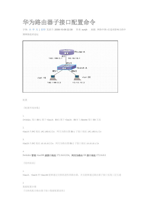
华为路由器子接口配置命令字体: 小中大| 打印发表于: 2008-10-09 22:38 作者: sunjh 来源: 网络中国--打造有影响力的中国网络技术论坛配置『配置环境参数』1.SwitchA 端口E0/1属于vlan10,E0/2属于vlan20,E0/3与Router端口E0互连2.vlan10内PC地址192.168.0.2/24,网关为路由器E0.1子接口地址192.168.0.1/243.vlan20内PC地址10.10.10.2/24,网关为路由器E0.2子接口地址10.10.10.1/244.SwitchA管理vlan100虚接口地址172.16.0.2/24,网关为路由E0接口地址172.16.0.1『组网需求』1.vlan10、vlan20和vlan100能够通过交换机透传到路由器,并且能够通过路由器子接口实现三层互通2数据配置步骤『交换机配合路由器子接口数据配置流程』一般来说交换机与路由器子接口配合,都因为交换机是二层交换机,没有三层路由功能,通过路由器终结二层交换机透传过来的vlan数据包,实现三层互通,是此类组网的主要目的。
在路由器子接口之间,各个网段之间为直连路由,如果要实现某些网段之间的访问控制,一般通过在路由器上配置访问控制列表来实现。
三层交换机由于本身支持多个虚接口,可以直接实现多网段之间的三层互通,一般不涉及此类组网。
【SwitchA相关配置】1.创建(进入)vlan10[SwitchA] vlan 102.将E0/1加入到vlan10[SwitchA-vlan10]port Ethernet 0/13.创建(进入)vlan20[SwitchA]vlan 204.将E0/2加入到vlan20[SwitchA-vlan20]port Ethernet 0/25.实际当中一般将上行端口设置成trunk属性,允许vlan透传int e0/3[SwitchA-Ethernet0/3]port link-type trunk6.允许所有的vlan从E0/3端口透传通过,也可以指定具体的vlan值[SwitchA-Ethernet0/3]port trunk permit vlan all7.创建(进入)vlan100[SwitchA]vlan 1008.vlan100可以不包含具体的端口9.创建(进入)vlan100的虚接口[SwitchA]interface Vlan-interface 10010.给vlan100的虚接口配置IP地址[SwitchA-Vlan-interface100]ip address 172.16.0.2 255.255.255.011.设置E0/3端口PVID为100,将管理vlan100送出去的报文vlan标记剥去,送往路由器主接口[SwitchA-Ethernet0/3]port trunk pvid vlan 10012.如果需要允许其它网段与交换机管理vlan地址互通,需要配置一条默认路由[SwitchA]ip route-static 0.0.0.0 0.0.0.0 172.16.0.1【RouterA相关配置】1.创建(进入)E0.1子接口[RouterA]inter Ethernet 0.12.在E0.1子接口里封装vlan10[RouterA-Ethernet0.1]vlan-type dot1q vid 103.在E0.1子接口配置IP地址[RouterA-Ethernet0.1]ip address 192.168.0.1 255.255.255.04.创建(进入)E0.2子接口[RouterA]inter Ethernet 0.2在E0.2子接口里封装vlan20[RouterA-Ethernet0.2]vlan-type dot1q vid 206.在E0.2子接口配置IP地址[RouterA-Ethernet0.2]ip address 10.10.10.1 255.255.255.07.进入E0接口[SwitchB-vlan20]port Ethernet 0[RouterA-Ethernet0]ip address 172.16.0.1 255.255.255.0【补充说明】1.如果一个端口是trunk端口,则该端口可以属于多个vlan2.缺省情况下trunk端口的PVID为1,可以在端口模式下通过命令port trunk pvid vlan vlanid 来修改端口的PVID3.一台交换机上如果已经设置了某个端口为hybrid端口,则不可以再把另外的端口设置为trunk端口3测试验证1.PC都能PING通自己的网关2.PC之间能够PING通3.交换机能够与路由器E0接口地址互通华为路由器交换机配置命令:计算机命令PCAlogin:root;使用root用户password:linux;口令是linux#shutdown-hnow;关机#init0;关机#logout;用户注销#login;用户登录#ifconfig;显示IP地址#ifconfigeth0netmask;设置IP地址#ifconfigeht0netmaskdown;禁用IP地址#routeadd0.0.0.0gw;设置网关#routedel0.0.0.0gw;删除网关#routeadddefaultgw;设置网关#routedeldefaultgw;删除网关#route;显示网关#ping;发ECHO包#telnet;远程登录华为路由器交换机配置命令:交换机命令[Quidway]discur;显示当前配置[Quidway]displaycurrent-configuration;显示当前配置[Quidway]displayinterfaces;显示接口信息[Quidway]displayvlanall;显示路由信息[Quidway]displayversion;显示版本信息[Quidway]superpassword;修改特权用户密码[Quidway]sysname;交换机命名[Quidway]interfaceethernet0/1;进入接口视图[Quidway]interfacevlanx;进入接口视图[Quidway-Vlan-interfacex]ipaddress10.65.1.1255.255.0.0;配置VLAN的IP地址[Quidway]iproute-static0.0.0.00.0.0.010.65.1.2;静态路由=网关[Quidway]rip;三层交换支持[Quidway]local-userftp[Quidway]user-interfacevty04;进入虚拟终端[S3026-ui-vty0-4]authentication-modepassword;设置口令模式[S3026-ui-vty0-4]setauthentication-modepasswordsimple222;设置口令[S3026-ui-vty0-4]userprivilegelevel3;用户级别[Quidway]interfaceethernet0/1;进入端口模式[Quidway]inte0/1;进入端口模式[Quidway-Ethernet0/1]duplex{half|full|auto};配置端口工作状态[Quidway-Ethernet0/1]speed{10|100|auto};配置端口工作速率[Quidway-Ethernet0/1]flow-control;配置端口流控[Quidway-Ethernet0/1]mdi{across|auto|normal};配置端口平接扭接[Quidway-Ethernet0/1]portlink-type{trunk|access|hybrid};设置端口工作模式[Quidway-Ethernet0/1]portaccessvlan3;当前端口加入到VLAN[Quidway-Ethernet0/2]porttrunkpermitvlan{ID|All};设trunk允许的VLAN [Quidway-Ethernet0/3]porttrunkpvidvlan3;设置trunk端口的PVID [Quidway-Ethernet0/1]undoshutdown;激活端口[Quidway-Ethernet0/1]shutdown;关闭端口[Quidway-Ethernet0/1]quit;返回[Quidway]vlan3;创建VLAN[Quidway-vlan3]portethernet0/1;在VLAN中增加端口[Quidway-vlan3]porte0/1;简写方式[Quidway-vlan3]portethernet0/1toethernet0/4;在VLAN中增加端口[Quidway-vlan3]porte0/1toe0/4;简写方式[Quidway]monitor-port;指定镜像端口[Quidway]portmirror;指定被镜像端口[Quidway]portmirrorint_listobserving-portint_typeint_num;指定镜像和被镜像[Quidway]descriptionstring;指定VLAN描述字符[Quidway]description;删除VLAN描述字符[Quidway]displayvlan[vlan_id];查看VLAN设置[Quidway]stp{enable|disable};设置生成树,默认关闭[Quidway]stppriority4096;设置交换机的优先级[Quidway]stproot{primary|secondary};设置为根或根的备份[Quidway-Ethernet0/1]stpcost200;设置交换机端口的花费[Quidway]link-aggregatione0/1toe0/4ingress|both;端口的聚合[Quidway]undolink-aggregatione0/1|all;始端口为通道号[SwitchA-vlanx]isolate-user-vlanenable;设置主vlan[SwitchA]isolate-user-vlansecondary;设置主vlan包括的子vlan [Quidway-Ethernet0/2]porthybridpvidvlan;设置vlan的pvid[Quidway-Ethernet0/2]porthybridpvid;删除vlan的pvid[Quidway-Ethernet0/2]porthybridvlanvlan_id_listuntagged;设置无标识的vlan 如果包的vlanid与PVId一致,则去掉vlan信息.默认PVID=1。
- 1、下载文档前请自行甄别文档内容的完整性,平台不提供额外的编辑、内容补充、找答案等附加服务。
- 2、"仅部分预览"的文档,不可在线预览部分如存在完整性等问题,可反馈申请退款(可完整预览的文档不适用该条件!)。
- 3、如文档侵犯您的权益,请联系客服反馈,我们会尽快为您处理(人工客服工作时间:9:00-18:30)。
系统处按下按键PARAM 然后选择网路设置IP地址 子网路遮罩 预设闸道 分别和电脑处上 述相对应,然后重新启动系统
系统启动后.在电脑桌面上打开第一步安装的软件Recon Shop Floor 软件然后点击Option
1 2
3 4
5
6 7
8
9
10
11
12
Shop Floor软件 如图双点击安装 如图网上邻居单击右键点属性
出现本地连接后单击右键在点属性 在Internet 协议 (TCP/IP) 点击属性
设置IP地址 子网掩码 默认网关 此处设置 IP地址和宝元系统IP地址只需最后一位数值不一样 例如:电脑设置为192.168.1.12 机床 系统设置为192.168.1.10 如果一台电脑连接多台机床时候只要设置IP不重复即可
系统处此时也可按照以前方式进行文件复制,复制文件选择盘为Z盘
THE END
然后点击依次点击1. Language(语言) (接受) 然后关闭
2. chinese simplified (简体中文) 3. apply
点击选项在分享目录处点击此处为设置上传程式目录文件所在位置,选择后确定即可
选择目录文件位置
重新打开桌面Recon shop floor 软件 (此时已经变为中文界面) 点击机台连接后在IP位址 处输入系统里设置的IP地址, 机台名称为:lncdos (如果连接多台系统时,设置对应
当第一次连接或新的电脑IP连接时候画面会提示出现未授权字样 ,此时系统处会出现远端来 讯画面,在系统处按下是选项,然后再点击断线,再重新点击连线即可
出现如图画面表示网络已经连接OK
点击档案即可进行加工程式的上传和下载 PC端为电脑处资料.NC端为机台系统处资料 注: 1.系统在自动状态时,为不可操作. 2. 该软件在关闭状态为不可传输程式