EG8030_datasheet
最新EG8010芯片手册
7. 电气特性 ........................................................................................................................................................... 11
1. 更新典型应用电路图(短路保护 LM393 部分),及应用图中 IR2103 驱动器到 IR2106 驱动器。
2. 添加工频变压器正弦波逆变器应用电路图。 1. 添加 EG8010+IR2110+闭锁功能典型应用图及更新典型应用
电路图参数。
2. 修改图 8.9a RS232 光耦隔离通讯电路中 MAX232 芯片的 9 脚和 10 脚连接。
7.2
典型参数 ........................................................................................................................................................................................................................................................................................ 7
4.1. 引脚定义 ............................................................................................................................................. 5
EG8405datasheet_V1.0
3W防失真、超低EMI立体声D类音频功放版本变更记录3W防失真、超低EMI立体声D类音频功放目录1. 特点 (3)2. 概述 (3)3. 应用领域 (4)4. 引脚 (4)4.1. 引脚定义 (4)4.2. 引脚描述 (4)5. 结构框图 (5)6. 典型应用电路 (6)7. 电气特性 (6)7.1 极限参数 (6)7.2 典型参数 (7)7.3 直流特性 (7)7.4 交流特性 (7)7.5 模拟特性 (8)8. 应用信息 (8)8.1工作模式 (8)8.2防失真功能(NCN) (9)8.3电源退耦 (10)8.4输入电容 (10)8.5模拟基准旁路电容(C BYP) (10)8.6电源开启/关闭时噼噗噪声 (11)8.7欠压锁定(UVLO) (11)8.8短路电流保护(SCP) (11)8.9过温保护(OTP) (11)8.10电磁辐射(EMI) (11)9. 封装尺寸 (12)3W防失真、超低EMI立体声D类音频功放EG8405芯片数据手册V1.01. 特点⏹防失真功能⏹宽的工作电源2.5V-5.5V⏹超优异的全带宽EMI抑制性能⏹免LC滤波器数字调制,直接驱动扬声器⏹高输出功率:3.0W@PVDD=VDD=5.0V,R L=4Ω,THD+N=10%⏹高效率:88%@PVDD=VDD=5.0V, R L=4Ω,P O=1W⏹低THD+N:0.1%@PVDD=VDD=5.0V, R L=4Ω,P O=1W⏹通道隔离度:80dB@f IN=1KHz,A V=18dB⏹高信噪比SNR: 90dB@ PVDD=VDD=5.0V, A V=18dB⏹优异的“噼噗-咔嗒”(Pop-Click)噪声抑制性能⏹关断功能⏹过流保护功能⏹过热保护功能⏹欠压保护功能⏹无铅SOP16封装2. 概述EG8405是一款带防失真功能且具有超低EMI的立体声免输出滤波器D类音频功率放大器。
在电源电压5V、THD+N=10%、4Ω负载的条件下,输出高达3W的功率,在性能与AB类放大器相媲美的同时,效率高达88%。
EG3012芯片数据手册说明书

ELECTRONIC GIANT大功率MOS管、IGBT管栅极驱动芯片屹晶微电子有限公司版本变更记录版本号日期描述V1.0 2012年06月06日EG3012数据手册初稿屹晶微电子有限公司目录1. 特点 (4)2. 描述 (4)3. 应用领域 (4)4. 引脚 (4)4.1. 引脚定义 (4)4.2. 引脚描述 (4)5. 结构框图 (5)6. 典型应用电路 (5)7. 电气特性 (7)7.1 极限参数 (7)7.2 典型参数 (8)7.3 开关时间特性及死区时间波形图 (9)8. 应用设计 (10)8.1Vcc端电源电压 (10)8.2输入逻辑信号要求和输出驱动器特性 (10)8.3自举电路 (11)9. 封装尺寸 (12)9.1 SOP8封装尺寸 (12)屹晶微电子有限公司EG3012芯片数据手册V1.01. 特点⏹高端悬浮自举电源设计,耐压可达100V⏹内建死区控制电路⏹电源电压欠压关断输出⏹自带闭锁功能,彻底杜绝上、下管输出同时导通⏹采用半桥达林顿管输出结构具有大电流栅极驱动能力⏹专用于无刷电机N沟道MOS管、IGBT管栅极驱动⏹HIN输入通道高电平有效,控制高端HO输出⏹LIN输入通道高电平有效,控制低端LO输出⏹外围器件少⏹静态电流小:4.5mA⏹封装形式:SOP-82. 描述EG3012是一款高性价比的大功率MOS管、IGBT管栅极驱动专用芯片,内部集成了逻辑信号输入处理电路、死区时控制电路、欠压关断电路、闭锁电路、电平位移电路、脉冲滤波电路及输出驱动电路,专用于无刷电机控制器中的驱动电路。
EG3012高端的工作电压可达100V,Vcc的电源电压范围宽11V~30V,静态功耗低仅4.5mA。
该芯片具有闭锁功能防止输出功率管同时导通,输入通道H IN和L IN内建了一个10K下拉电阻,在输入悬空时使上、下功率MOS管处于关闭状态,输出结构采用半桥式达林顿管结构,采用SOP8封装。
3. 应用领域⏹电动摩托车控制器⏹电动自行车控制器⏹100V降压型开关电源⏹变频水泵控制器⏹无刷电机驱动器⏹高压Class-D类功放4. 引脚4.1. 引脚定义IN IN图4-1. EG3012管脚定义4.2. 引脚描述5. 结构框图H LOGNDVccHOVS VBL图5-1. EG3012结构框图6. 典型应用电路+15V+VinH L OUT图6-1. EG3012典型应用电路图——中、小功率半桥驱动应用屹晶微电子有限公司+15V+VinH L OUT图6-2. EG3012典型应用电路图——大功率电机场合应用+15V+VinH L OUT图6-3. EG3012典型应用电路图——外接自举二极管应用7. 电气特性7.1 极限参数注:超出所列的极限参数可能导致芯片内部永久性损坏,在极限的条件长时间运行会影响芯片的可靠性。
基于EG8030的矿用移动式三相逆变电源设计
基于EG8030的矿用移动式三相逆变电源设计在不改变原先用电设备的情况下,解决煤矿井下的临时用电问题,需要设计一种矿用三相移动式逆变电源来实现。
文章介绍一种逆变电源,由大容量锂电池组提供直流输入,智能功率模块IPM内含逆变主电路和驱动及保护电路,EG8030作为逆变控制芯片实现SPWM波输出,检测电路采集电池电压和逆变电压信号,单片机实现逆变器的启停和三相SPWM调制深度控制。
标签:矿用;三相逆变;SPWM1 概述煤矿井下施工过程中,经常需要进行设备的拆装、搬运、检修、维护,需要临时用电。
然而,煤矿井下的供电通常是由井下中央变电所通过敷设输电线路供给电能的方式实现,这种供电方式只适用于设施固定、长期运行的场所。
因此,煤矿井下迫切需要一种无需敷设供电线路的移动逆变电源,能够满足临时工作场所的照明和电动工具的使用。
本文设计了一款矿用移动式三相逆变电源,可以提供容量2KV A的三相交流50Hz、127V电源,能够应用于井下部分区域的照明和煤电钻用电,为井下施工及意外事故提供临时用电,弥补了当前井下集中供电方式的输电线路长、安装周期长等不足。
2 系统方案设计矿用移动式三相逆变电源的电路构成如图1所示,由大容量锂电池模块组、三相逆变主电路、逆变控制电路、人机界面和电池电压检测、交流输出检测电路组成。
锂电池选用磷酸铁锂电池模块,标称电压48V,标称容量100Ah。
5组电池组模块串联连接,锂电池组总输出直流电压为240V,作为三相逆变主电路的输入。
逆变主电路使用智能功率模块IPM,选用FUJI electric的IGBT-IPM模块6MBP30RH060,这款IPM模块内部集成6组绝缘栅双极型晶体管(IGBT,Insulated Gate Bipolar Transistor)及其驱动电路,额定电流30A,耐压600V,内部集成了过电流保护(OC)、短路保护(SC)、控制电源欠压保护(UV)、过热保护(管壳过热TcOH、芯片过热TjOH)等保护电路,且可通过向IPM相连的MCU输出报警信号(ALM),确保系统停止工作。
相序表 MODEL 8030 使用说明书
使用说明相序表MODEL 8030目录1.安全警告2.特性3.技术规格4.仪表布局图5.测量与检测方法5-1 测量方法5-2 检测方法1.安全警告仪器符合国际安全标准IEC-348:是测量电气设备的安全必备品,出厂前产品检验完全合格。
说明书里包括警告和安全规则,请务必严格遵守以确保操作安全。
因此,使用此仪表前,务必通读这些操作说明。
仪表上标志,提醒用户在安全操作仪表时,必须参阅说明书中相关操作说明。
务必阅读说明书中标志后的内容。
危险:表示操作不当可能会导致严重或致命的伤害。
警告:表示操作不当可能会导致严重或致命的伤害。
小心:表示操作不当可能会导致人身伤害或仪表的毁坏。
警告1、测量时,请勿拆开仪器。
2、若仪器出现以下情况,请勿进行测量,请对仪表进行检修。
a) 仪器存在明显损坏。
b) 测试导线断裂。
c) 无法测量。
d) 在不适宜条件下贮存过长时间。
e) 遭受剧烈运输重压。
3、三相电线内存在高压。
若触电将非常危险,在仪器与三相线连接时务必小心。
4、若所有开相指示灯均未点亮,有可能其中一相带电。
请小心避免触电。
小心1、请勿超过额定工作电压200~480V(三相交流)。
2、在200V上连续测量时间请勿超过60分钟,在480V上连续测量时间请勿超过4分钟,以上时间从2根测试导线与电源线连接后算起。
3、“吸盘”表面一定要保持清洁,使用前,请用一块软布擦去表面灰尘或油垢。
4、请勿将仪表暴露在阳光、高温、潮湿、露水环境里。
5、仪器必须由有经验的专业人员严格按使用说明书中指示进行操作。
对于因错误使用仪器而造成的人身事故或仪器损坏,本公司概不负责。
请务必理解并遵守说明书中的安全操作说明。
2.特性仪器可检查是否开相,也可测量相序。
3.技术规格工作电压: 200V~480V AC连续使用时间: 200V:60分钟内;480V:4分钟内工作频率范围:20~400 Hz耐压: 4000V AC一分钟体积:80(L)×59(W)×23(D)mm重量:约200克附件:双绝缘线长1米,测试线(带探棒),说明书,便携外壳4、仪表布局图①. 开相检查指示灯:3个桔色指示灯②. 相序检查指示灯:绿色为正相,红色为反相③. 吸盘:方便安装在配电盘等设备上④. 测试线:红色为L1(R),白色为L2(S),蓝色为L3(T)⑤. 鳄口夹:可夹在直径不超过10mm的电线或端子上⑥. 手提带⑦. 探棒5.测量与检测方法5-1 测量方法将鳄口夹与被测三相线路连接。
基于EG8030单相变三相纯正弦波电路设计
2021 年 2 月 25 日第 38 卷 第 4 期
林春景,等:基于 EG8030 单相变三相 纯正弦波电路设计
Telecom Power Technology
Feb. 25, 2021 Vol.38 No.4
相对称 380 V 交流电。
图 2 工频变压电路
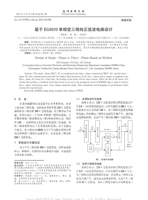
上述两个方案都能产生三相对称 380 V 交流电, 有三相不对称保护功能,但方案 1 采用斩波升压电路 虽然体积小,重量轻,但是可靠性差,而由于方案 2 工频升压电路的隔离,使得电动机对逆变器的冲击较 小,可靠性高,所以决定采用方案 2 进行设计。
摘要:将单相 220 V 交流转变为三相对称 380 V 交流,转变后的三相交流一般都夹杂着较高的三次谐波,如果 用这种三相电源长时间给三相交流电机供电,将会导致电机发热严重,从而影响电机的寿命。为了解决这个问题, 利用 EG8030 芯片能产生自带死区控制的三相纯正弦波信号的特点,对芯片外围电路设置反馈保护电路,使它工作在 三相同步开环调压模式。经安装和调试,其性能指标达到预期目标。
关键词:EG8030;单相变三相;SPWM
Design of Single-Phase to Three-Phase Based on EG8030
LIN Chunjing1, CUI Xiao1, LIU Jiefeng2 (1.Guangdong Baiyun University Electronic and Information Engineering Departna;
Keywords: EG8030; single phase transition three phases; SPWM
0 引 言
在某些偏僻地区或家庭中仅有单相供电,但却 又要用到三相负载,这时就必须将单相 220 V 交流电 源转换为三相对称 380 V 交流电源。为了解决这个问 题,本项目设计一个 3 kW 单相变三相供电系统。大 多数单相变三相电路采用三相 PWM 控制方式,相位 差 120°,这种供电方案会含有较高的三次谐波,供 给三相电机时间长了会导致电机发热。为了克服这 个缺点,本文利用 EG8030 芯片产生功能完善的自带 死区控制的三相纯正弦波信号,从而实现三相对称 380 V 交流供电。
Datasheet MLX90614 中文 数据手册 rev008
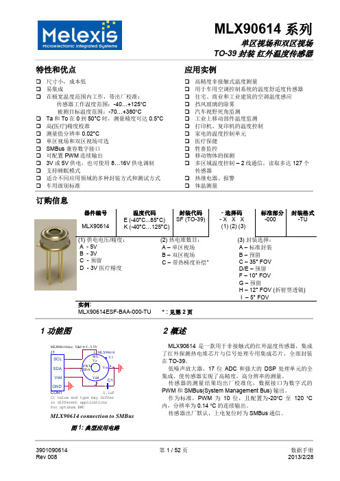
10-位 PWM 输出模式是连续输出所测物体温度的标准配置,测量物体的温度范围为-20…120 °C,分辨 率为 0.14 °C。PWM 通过修改 EEPROM 内 2 个单元的值,实际上可以根据需求调整至任何温度范围,而这对 出厂校准结果并无影响。
传感器的测量结果均出厂校准化,数据接口为数字式的 PWM 和 SMBus(System Management Bus) 输出。
作为标准,PWM 为 10 位,且配置为-20˚C 至 120 ˚C 内,分辨率为 0.14 ˚C 的连续输出。
传感器出厂默认,上电复位时为 SMBus 通信。
3901090614 Rev 008
PWM 引脚也可配置为热继电器(输入是 To),这样可以实现简单且性价比高的恒温控制器或温度报警(冰 点/沸点)应用,其中的温度临界值是用户可编程的。在 SMBus 系统里,这个功能可以作为处理器的中断信号, 以此触发读取主线上从动器的值,并确定精度条件。
传感器有两种供电电压选择:5V 或 3V(电池供电)。其中,5V 也可简便的从更高供电电压(例如 8 至 16V)上通过外接元件调制。(具体请参考“应用信息”)
MLX90614 connection to SMBus
图 1: 典型应用电路
2 概述
MLX90614 是一款用于非接触式的红外温度传感器,集成 了红外探测热电堆芯片与信号处理专用集成芯片,全部封装 在 TO-39。
低噪声放大器、17 位 ADC 和强大的 DSP 处理单元的全 集成,使传感器实现了高精度,高分辨率的测量。
Genelec 8030.LSE PowerPak
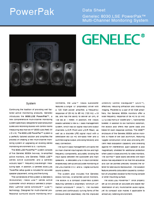
Continuing the tradition of providing well fac-tored active monitoring products, Genelec introduces the 8030.LSE PowerPak™, a new comprehensive multi-channel monitoring system specifically designed for post-production suites and recording studios with control rooms measuring less than 85 m3 (3000 cubic feet) (W x D x H). The 8030.LSE PowerPak™ system is a perfectly tailored solution and simplifies the process of creating a new multi-channel moni-toring system or upgrading an existing stereo monitoring environment to 5.1 surround.The 8030.LSE PowerPak™ system consists of five Genelec 8030A two-way, bi-amplified active monitors, one Genelec 7060A LSE™ Series Active Subwoofer, and a Genelec Acousti/T ape™ frequency/wavelength mea-suring tape. In addition, a Genelec 8030.LSE PowerPak setup guide is included for accurate speaker placement, wiring and fine-tuning. The cornerstone of the system is Genelec’s revolutionary 7060A LSE™ Series Active Subwoofer which employs Genelec’s propri-etary Laminar Spiral Enclosure™ (LSE™) technology. Designed for multi-channel pro-fessional surround sound monitoring envi-ronments, the LSE™ 7060A subwooferfeatures a single 10” proprietary driver witha 120 Watt power amplifier, a frequencyresponse of 29 Hz to 85 Hz (120 Hz) +/-3dB, and has the ability to deliver an SPL of108 dB at 1 meter. In addition, the 7060Aboasts Genelec’s new 6.1 bass managementsystem, which has six signal input and outputchannels (L/C/R Front and L/C/R Rear), aswell as a discrete LFE signal input with aselectable 85/120 Hz low-pass filter and asummed signal output, providing flexibility andeasy connection.The built-in bass management unit splits thesix main channel input signals into low and highfrequency components, accurately dividing theinput signal between the subwoofer and mainspeakers. A dedicated LFE In input connectorenables easy set-up and accurate monitoring ofthe LFE channel in 5.1 and 6.1 digital surroundsound systems.The system also includes five Genelec8030A two-way, bi-amplified active monitors.The 8030A is a compact close-field systemfeaturing Genelec’s proprietary Minimum Dif-fraction Enclosure™ (MDE™). The roundedcorners and continuously curving forms of theenclosure blend seamlessly into the improvedDirectivity Control Waveguide™ (DCW™),effectively reducing diffraction and improvingimaging. Powered by a pair of 40 Watt ampli-fiers, the Genelec 8030A monitors offer awide frequency response of 58 Hz to 20 kHz(+/-2.0 dB) from a 5” woofer and 3/4” hard-domedtweeter. In addition to low harmonic distortion,the 8030A also offers rear panel bass andtreble tilt room response controls. The MDE™enclosure of the Genelec 8030A active moni-tors is made of die cast aluminum, featuringrugged construction while also providing effi-cient heat dissipation capability and shieldingagainst RF interference. Each speaker is alsomagnetically shielded for additional protectionwhen used in close proximity to video monitors.The Iso-Pod™ table stand delivered with each8030A has adjustable tilt so that the acousticalaxis can be pointed precisely towards the lis-tener for best sound reproduction. The isolationfeature prevents colouration caused by conduc-tion of unwanted vibration to the mixing consoleor other mounting surface.The 8030.LSE PowerPak™once properlyset up will provide an accurate and stable rep-resentation of any multichannel audio signal,yet its compact size makes it applicable toalmost any listening environment.SystemGenelec Document BBAGE030. Copyright Genelec Oy 1.2005. All data subject to change without prior noticeInternational enquiries: Genelec, Olvitie 5FIN-74100, Iisalmi, Finland Phone +358 17 83881Fax +358 17 812 267************************In the U.S. please contact Genelec, Inc., 7 T ech Circle Natick, MA 01760Phone 508 652 0900Fax 508 652 0909****************************Subsonic filterConnectors 7 XLR female (6 Main + 1 LFE)XLR pin sequence pin 1 gnd Input level for 100 dB SPL Crossover frequency, Crossover slopes 36 dB/octaveBass roll-off control operating From 0 to –6 dB @ 30 Hz in 90° stepsfree field @ 1 m on axisDimensionsShort term amplifier outputpower (Long term output power is limited by driver unit protection circuitry)Amplifier system distortion at nominal output Power consumption (average)Free field frequency response 29 Hz…85 Hz (+/- 3 dB) (Main channels)Maximum short term sine wave ≥ 100 dB SPL Self generated noise level in (A-weighted)Harmonic distortion @ 95 dB SPL@ 85 dB SPL205 mm (10”) 130 mm (5”) woofer527 mm (20 3/4”) 299 mm (11 13/16”)*7060A (18 dB/octave) below 29 HzUpper bandwidth/LFE cutoff 85 Hz/120 Hz selectableInput Output 7 XLR male (6 Main + 1 Sum Out) pin 2 + pin 3 -Input impedance10 kOhm balancedoutput @ 1 m Variable from +6 to –12 dBu (sub/main channels) 85 Hz Lowpass Highpass 12 dB/octave Midband rejection >400 Hz ≥ 50 dBrange in 2 dB stepsPhase matching control From 0 to 270° @ 85 HzBypass Bypasses the bass management for the main channels LFE sensitivity Adjustable 0 / +10 dBRedirect Redirects LFE channel signal above 85 Hz to center channel Sum InChanges subwoofer to Sum In mode, main inputs defeated T est tone for phase adjustment 85 HzRemote LED connector (RJ11)Input for optional Power/Overload+Bypass remote controls120 W40 W Mains voltage 220, 230, 240, 100/200 100, 120, 220 or 230 Vto region 15 VA 10 VA7060A 8030A 58 Hz...20 kHz≥ 108 dB SPL averaged SPL outputMaximum peak SPL output ≥ 113 dB SPL ≥ 106 dB SPL ≤ 15 dB ≤ 10 dB< 2 % < 2 % (50...150 Hz)< 0.5 % (> 150 Hz)Drivers (Magnetically shielded)19 mm (3/4”) dome tweeter Weight 26 kg (57 lbs) 5.6 kg (12.3 lbs) Height Width 462 mm (18 316”) 189 mm (7 7/16”) Depth 360 mm (14 3/16”) 178 mm (7”)*Including Iso-Pod™ table stand7060A8030ABass Treble N/A 40 WTHD ≤ 0.05 %≤ 0.05 %or 115/230 V according according to regionIdle Full output150 VA80 VARecommended listening 1.7 to 2.5 m (5 to 8 ft)T RMS SPL all channels driven(3000 cubic feet)8030.LSE PowerPak distanceypical max short term108 dB, Flat response weightingSuggested acoustic space max. 85 m In China please contact:Genelec China Representative Office Soho New Town, 88 Jianguo Road D-1504, Chaoyang District Beijing 100022, ChinaPhone +86 10 8580 2180 Fax +86 10 8580 2181******************************。
LTC1980EGN#PBF;LTC1980EGN;LTC1980EGN#TR;LTC1980EGN#TRPBF;中文规格书,Datasheet资料
1 /2/31980fELECTRICAL CHARACTERISTICSSYMBOL PARAMETERCONDITIONS MIN TYP MAX UNITS V RCHG2Recharge Threshold, Delta Voltage with Respect BATT 1 = Open 60mVto Float Voltage, Measured at OVP V LT0Charger Shorted Cell Threshold BATT2 = 0 2.55 2.7 2.8V V LT1Charger Shorted Cell ThresholdBATT2 = 15.25.4 5.65V I BLDO Input Bias Current, Low Dropout Regulator Measured at LDOFB Pin1.0µA g mldo Transconductance, Low Dropout Regulator Measured from LDOFB to LDODRV350µmhosV OLLDO Output Low Voltage, Low Dropout Regulator 0.1V V OHLDO Output High Voltage, Low Dropout Regulator V REG – 0.1V I OUTLDO Low Dropout Regulator Output Current, Source/Sink ±20µA A VOL Error Amplifier Open-Loop Voltage Gain From REGFB to V C60dB I BEA Error Amplifier Input Bias Current –0.10.1µA V OLEA Error Amplifier Output Low Voltage 00.5V V OHEA Error Amplifier Output High Voltage SS = Open1.42V I OUT Error Amplifier Output Source Current 0.5mA Error Amplifier Output Sink Current–1.2mA g mflt Float Voltage Error Amplifier Transconductance Measured from OVP to SS,65µmhosCharger Mode, BATT1 = OpenI BFLT Float Voltage Error Amplifier Input Current –0.10.1µA (Measured at OVP Input)V OS1Current Amplifier Offset Voltage –66mV I BIS Input Bias Current, I SENSE Input –100µA A VCA Current Amplifier Voltage Gain Measured from I SENSE to 2.32.44 2.55V/V CAOUT PinR PROG PROG Pin On Resistance 400ΩI PROG PROG Pin Leakage Current 100nA f S Switching Frequency ●260300340kHz t r , t f Driver Output Transition Times C L = 15pF 10ns t BREAK Driver Output Break Times V BAT = V REG = 10V 100ns f TIMER Timer Frequency C = 1000pF4.5kHz I TIMER1TIMER Pin Source Current –4µA I TIMER2TIMER Pin Sink Current 4µA R REG REG On Resistance 68ΩI REGPD REG Pull-Down Current 259µA I REGLK REG Leakage Current 60nA V VTHREG REG Logic Threshold0.3 1.3V V IL1Digital Input Low Voltage,V REG = 5V 1.185 1.221 1.247V Negative-Going, Wall Adapter (WA)V IH1Digital Input High Voltage,V REG = 5V1.1951.226 1.257V Positive-Going, Wall Adapter (WA)V IL2Digital Input Low Voltage, BATT1100mV V IH2Digital Input High Voltage, BATT1V BIAS2V–100The ● denotes the specifications which apply over the full operatingtemperature range, otherwise specifications are at T A = 25°C. V BAT = 2.4V, V REG = 5V, V BAT unloaded./1980 G06V BAT = 3.6V100µs/DIVV REG≅ 3.3VI L = 100mA TO 500mAT A = 25°CFIGURE 54/1µs/DIV V BAT = 3.6VV REG = 3.3VT A = 25°CI L = 500mA 1980 G071µs/DIVV BAT = 3.6VV REG = 3.3VI L = 500mAT A = 25°CFIGURE 51980 G081µs/DIVV BAT = 3.6VV REG≅ 3.3VI L = 500mAMODE = V BIAS1T A = 25°C1980 G09200µs/DIV V BAT = 3.6VV REG = 3.3VI L = 10mAT A = 25°CFIGURE 51980 G10500µs/DIVV BAT = 3.6VV REG = 3.3VV LDO = 3.1VI LDO = 200mAV WALL ADAPTER = 6V TO 0V1980 G11500µs/DIVV BAT = 3.6VV REG = 3.3VV LDO = 3.1VI LDO = 200mAV WALL ADAPTER = 0V TO 6V1980 G125ms/DIVC TIMER = 0.24µFT A = 25°C1980 G14/5UUUPI FU CTIO SPROG (Pin 1): Charge Current Ratio Programming Pin. Programs the full charge current when the charger is in the constant current mode. A resistor placed between the PROG pin and the PROGT pin (Pin 2) determines the charge current. The PROG pin connects to an open drain MOSFET which turns on for full current and is off when trickle charging.PROGT (Pin 2): Trickle Charge Programming Pin. Pro-grams the trickle charge current for a deeply discharged battery. Two resistors are used, one between the PROGT pin and CA OUT (Pin 22) and another from PROGT to ground. A capacitor between the PROGT pin and V C (Pin 4) provides compensation for the constant current feed-back loop.REGFB (Pin 3): DC/DC Converter Feedback Pin. This pin is used to program the DC/DC converter output voltage when the LTC1980 is in the DC/DC (regulator) converter mode. An external resistor divider from V REG to REGFB to ground programs the output voltage. The virtual reference voltage (V REF) on this pin is 1.225V. A series RC from the REGFB pin to V C (Pin 4) provides pole-zero compensation for the regulator outer loop.V C (Pin 4): Control Signal of the Inner Loop of the Current Mode PWM. A common current mode loop is used by the battery charger and voltage regulator functions. Minimum duty factor (measured on BGTDR (Pin 14) in regulator mode and RGTDR (Pin 11) in charger mode) occurs at approximately 1V. Duty factor increases as V C increases. This part includes slope compensation, so there is some variation in V C for minimum and maximum duty factor as V REG or V BAT is varied.LDO FB (Pin 5): Low Dropout Regulator F eedback Pin. This pin is used to program the low dropout linear regula-tor output voltage. An external resistor divider from the output of the LDO regulator (drain of the external MOSFET) to LDOFB to ground programs the output voltage. The virtual reference voltage on this pin is 1.225V. LDODRV (Pin 6): Low Dropout Error Amplifier Output. This pin drives the gate of an external PMOS pass transis-tor. This pin is pulled up to V REG (shutting off the pass transistor) if MODE (Pin 16) is grounded or if undervoltage occurs.V REG (Pin 7): Connection Point to the DC/DC Converter Side of the Combo Charger/Converter Circuit.WA (Pin 8): Wall Adapter Comparator Input. An external resistor divider from the wall adapter output to WA to ground sets the threshold which determines if charging can occur. If the wall adapter is below this threshold, the LTC1980 assumes the wall adapter is not present and the charger shuts down. Wall adapter sense threshold is set higher than the DC/DC converter output voltage to insure correct operation.BATT1 (Pin 9): Logic Input Pin for Selecting Preprogrammed Li-Ion Charge Voltage. See Truth Table logic settings.BATT2 (Pin 10): Logic Input Pin for Selecting Preprogrammed Li-Ion Charge Voltage. The following combinations of BATT1 and BATT2 select the correct Li-Ion charge voltage. See Truth Table.BATT2BATT1FLOAT VOLTAGE00 4.1V01 4.2V108.2V118.4VDon’t Care Open Externally Set Via OVP Logic 1 = V BIAS2 (Pin 19), Logic 0 = GNDRGTDR (Pin 11): DC/DC Converter (Regulator) Side Gate Drive Pin. This pin provides gate drive to the external MOSFET (REG-FET) that connects to V REG via the trans-former.PGND (Pin 12): Power Ground. Refer to the Applications Information section for proper use of ground and power ground connections.V BIAS1 (Pin 13): Internally Generated Power Bus. Bypass this pin with a 1µF or larger ceramic capacitor (or other low ESR capacitor) to PGND (Pin 12). Do not connect any load to this pin.BGTDR (Pin 14): DC/DC Converter (Battery) Side Gate Drive Pin. This pin provides gate drive to the external MOSFET (BAT-FET) that connects to V BAT via the trans-former./61980fREG (Pin 15): Bidirectional Regulator Mode Control Pin. A pull-up resistor is required between this pin and V BIAS2. This pin is open when charging normally, has a weak pull-down (approximately 5µA) when conditioning the battery and a strong pull-down when in regulator mode. Pulling this pin low forces the IC into regulator mode.MODE (Pin 16): Selects different operating modes in both charger and DC/DC converter configurations. Also en-ables and disables Burst Mode operation. See Mode Pin Operation table in Application section.TIMER (Pin 17): A timing capacitor on this pin determines the normal charge time for charge termination.C(µF) = 0.25 • Time (Hours)V BAT (Pin 18): This pin connects to the positive terminal of the battery and the battery side of the power converter. V BIAS2 (Pin 19): Internally Generated Voltage. Bypass this pin with a 1µF or larger ceramic capacitor (or other low ESR capacitor). Do not connect any load to this pin. GND (Pin 20): Signal Ground. This pin should Kelvin-connect to the current sense resistor (R SENSE).I SENSE (Pin 21): Current Sense Input Pin. Connects inter-nally to a current amplifier and zero current comparator. This pin should Kelvin-connect to the current sense resis-tor (R SENSE) .CAO UT (Pin 22): Current Amplifier Output. A program resistor connects between this pin and PROGT (Pin 2) to set the charge current (in constant-current mode). OVP (Pin 23): Overvoltage Protection. This pin connects to the tap on an optional external voltage divider con-nected across the battery. This allows nonstandard float voltages to be used for the battery charger. Overvoltage, restart and undervoltage thresholds will also be affected by the external voltage division ratio. To use this pin, BATT1 (Pin 9) must float.SS (Pin 24): Soft-Start. A capacitor between this pin and ground sets the battery charge ramp rate. Battery charge current is very low the moment after the converter switches from DC/DC converter (regulator) mode to battery charger mode then ramps up to final battery charge current from there. This insures that the wall adapter is not loaded down with a large inrush current that could prevent correct battery charger operation.The same capacitor, which sets the soft-start ramp rate, also sets the compensation for the battery float voltage control loop.UUUPI FU CTIO S/71980f8/9 /10 /分销商库存信息:LINEAR-TECHNOLOGYLTC1980EGN#PBF LTC1980EGN LTC1980EGN#TR LTC1980EGN#TRPBF。
Super Tigre SUPG8030 8040 8050 说明书
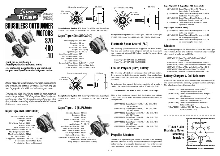
®BRUSHLESS OUTRUNNERMOTORS 370400.10(SUPG8030)(SUPG8040)(SUPG8050)Thank you for purchasing aSuperTigre brushless outrunner motor!This instruction manual will help you install and run your new SuperTigre motor and power system.Before you begin installing your new motor, please take thetime to review the specs of the motor. These will help you select a propeller size, ESC, and battery for your motor.The propeller sizes listed in the specs for each motor arefor electric propellers. “SF” designates a Slow Flyer type of electric prop, while “E” designates an Electric prop. Slow fl yer propellers are mainly used on smaller electric motorsthat turn at slower speeds.SuperTigre 370 (SUPG8030)Mounting Space: 26.6mmDiameter: 28mmLength: 26mm RPM/V (kV Rating): 1000Weight: 1.4oz (39g) Input Voltage: 7.4-11.1V Max. Constant Current: 11.5A Max Surge Current: 13A Max Constant Watts: 125W No Load Current: .7ASuggested Prop Sizes: 9x3.5SF - 11x4.7SF Connectors: 3.5mm Male Bullet Prop Adapter: 3mm (not included)Sample Power System 370: SuperTigre 370 motor, SuperTigre ST -20A ESC, SuperTigre 910mAh, 11.1V LiPo, 9x3.8SF propSuperTigre 400 (SUPG8040)Mounting Space: 31.5mmDiameter: 28mmLength: 30mm kV Rating: 950 rpm/VWeight: 1.8oz (50g) Input Voltage: 7.4-11.1V Max. Constant Current: 13A Max Surge Current: 18A Max Constant Watts: 145W No Load Current: .6ASuggested Prop Sizes: 9x3.5SF - 11x7SF Connectors: 3.5mm Male Bullet Prop Adapter: 3mm (not included)Sample Power System 400: SuperTigre 400 motor, SuperTigre ST -20A ESC, SuperTigre 1250mAh, 11.1V LiPo, 10x3.8SF propSuperTigre .10 (SUPG8050)Mounting Space: 38.7mmDiameter: 35mmLength: 30mm RPM/V (kV Rating): 1250Weight: 2.4oz (69g) Input Voltage: 7.4-11.1V Max. Constant Current: 29A Max. Surge Current: 33A Max. Constant Watts: 320W Max. Surge Watts: 370W No Load Current: 1.2ASuggested Propeller Size: 10x7E-11x7E Connectors: 3.5mm Male Bullet Prop Adapter: 4mm (not included)Sample Power System .10: SuperTigre .10 motor, SuperTigre ST -30A ESC, SuperTigre 2100mAh, 11.1V LiPo, 10x5E propElectronic Speed Control (ESC)The following speed controls are suggested for these motors.Y ou may use another brand of speed control, but make surethat you use a brushless ESC that can handle the current drawof your motor.SuperTigre ST -20A ESC (SUPM1020) SuperTigre ST -30A ESC (SUPM1030)Lithium Polymer (LiPo) BatteryThe following LiPo batteries are suggested for these motors. Of course, other batteries may be used but they must deliver the current that your particular motor & prop combination will draw.To determine the current delivering capability of a battery, multiply the capacity (mAh rating) by the “C” rating by 0.001.For example: 640mAh x 15C x 0.001 = 9.6 ampsThis is the maximum current that the battery can delivercontinuously. This is listed for these batteries in the column on the right side.(SUPP1010) S uperTigre 640mAh, 11.1V (3S), 15C LiPo 9.6A max(SUPP1020) S uperTigre 910mAh, 11.1V (3S), 15CLiPo 13.6A max(SUPP1030) S uperTigre 1250mAh, 11.1V (3S), 15CLiPo 18.7A max(SUPP1040) S uperTigre 1500mAh, 11.1V (3S), 15CLiPo 22.5A max(SUPP1050) S uperTigre 1800mAh, 11.1V (3S), 15CLiPo 27A max(SUPP1060) S uperTigre 2100mAh, 11.1V (3S), 15CLiPo 31.5A maxPropeller AdaptersIn order to fi t a propeller, you’ll need to use one of the following propeller adapters. Y ou may choose either the collet style or the set-screw style prop adapter depending on your preference or particular needs. These are listed by the motor(s) that they fi t.SuperTigre 370 & SuperTigre 400 (3mm shaft)(GPMQ4959) G reat Planes ® ElectriFly ™ 3mm to5mm Collet Prop Adapter(GPMQ4930) G reat Planes ElectriFly 3mm to 5mmSet Screw Prop Adapter(GPMQ4988) G reat Planes ElectriFly 3mm to 5mmSet Screw Adapter (cone nut)(GPMQ4620) G reat Planes ElectriFly Prop Saverstyle Prop Adapter SuperTigre .10 (4mm shaft)(GPMQ4965) G reat Planes ElectriFly 4mm to ¼-28collet prop adapter(GPMQ4936) G reat Planes ElectriFly 4mm to ¼-28set screw prop adapter(GPMQ4992) G reat Planes ElectriFly 4mm to ¼-28set screw adapter (cone nut)AdaptersThe following adapters are available for use with the SuperTigreline of motors, ESCs, and batteries. These will help you adaptother brands of batteries and ESCs.(SUPM0010) S uperTigre LiPo to Deans ® Ultra ®Female Plug (SUPM0020) S uperTigre LiPo to Deans Micro Plug(SUPM0030) S uperTigre LiPo to Standard Male Plug (SUPM0040) D eans Ultra Male to SuperTigre ESC (SUPM0050) D eans Micro to SuperTigre ESC (SUPM0060) S tandard Female to SuperTigre ESCBattery Chargers & Cell BalancersTo charge your batteries, you’ll need to have a battery chargerand a cell balancer or a specially equipped balancing charger.The following equipment is suggested: (GPMM3153) G reat Planes ElectriFly T riton 2™Charger/Discharger/Cycler(GPMM3015) G reat Planes ElectriFly PolyCharge 4™LiPo Charger(GPMM3160) G reat Planes ElectriFly Equinox ™ LiPoBalancer/Charge Interface(GPMM3156) G reat Planes ElectriFly T riton2 EQBalance Charger(HCAP0250) H obbico ® 12V DC Power Supply (forTriton 2 GPMM3153)ST 370 & 400Brushless MotorMounting TemplateSide 1Assemble Your Power SystemIf your kit or ARF already has instructions for mounting an electric motor, please rely on that instruction manual for the basic installation of your power system and use this one as a supplement. If you will be mounting this motor independently of any other instruction manual, please use the followinginstructions to help guide your installation.1. Remove the mount screw(s) and apply a drop of thread-locking compound (GPMR6060) onto the screw threads. Reinstall the mounting screw(s). Note: The SuperTigre 370 & 400 motors have one mount screw. The SuperTigre .10 has two mounting screws.2. Cut out the template that fi ts your motor and use tape or spray adhesive to attach it to your model’s fi rewall. Match the crosshairs of the template with those engraved on your model’s firewall.3. Use a 1/8" [3.2mm] drill bit to drill the motor mounting holesin the fi rewall. If you are mounting the SuperTigre 370 or 400motor, you will need to drill a hole in the center of your fi rewallto clear the motor mount, mount screw, and motor wires. Startwith a 3/8" [9.5mm] drill and enlarge the hole using a Dremel®rotary tool.4. Mount your motor to the fi rewall using the screws, washers,and blind nuts supplied with your model kit. 4-40 sized hardware or 3mm hardware is adequate for these SuperTigre motors. If you are using the SuperTigre 370 or 400 motor, route the motorwires through the notched cutout you made in the fi rewall. Apply a drop of thread-locking compound on the screw threads of each mounting screw. Note: The motor wires must be routed properly so they do not rub on the spinning motor case.5. Connect the motor wires to the ESC. Plug your ESC’s signal lead into your receiver. Turn on your transmitter and set the throttle to off position. Connect your LiPo battery to the ESC. Arm the motor using the procedure detailed in your ESC’s instruction manual. Check the direction of motor rotation. The motor should rotate counter-clockwise as viewed from the front of the airplane. If the motor rotates clockwise, unplug any two motor leads and swap their positions. Test the rotation direction once again. Note: If you have a Futaba radio system, please reverse the throttle channel (channel 3) before you plug in the LiPo battery. Warning: Do not attempt to do this with thepropeller attached!Install the PropellerTwo different types of prop adapters are available that are compatible with these motors. Please refer to the list of prop adapters earlier in this manual for the ones that fit your motor.1. If you are installing the set-screw type of prop adapter, remove the set screw(s) from the base of the prop adapter and apply a drop of thread-locking compound to each set screw’s threads. Fit the prop adapter to the motor shaft so that at leastone set screw is aligned directly over the fl at spot on the motor shaft. Slide the prop adapter all the way onto the motor shaftand tighten the set screw(s). The fl at spot and set screw(s) willkeep the prop adapter keyed to the motor shaft.2. If you are installing a collet type prop adapter, simply slide itonto the motor shaft as far as it goes.3. If your airplane has a cowl, install it now. Fit a balanced propeller to the prop shaft and install the prop washer and prop nut. Tighten the prop nut securely.4. Trim your cowl and make air vents for cooling air to fl ow over the motor, ESC, and battery(s). As a general rule, the area ofthe cooling air vent should be 3x the area of the cooling airinlet. This ensures positive airfl ow and will prevent the motor from overheating.SuperTigre Motor MaintenanceSuperTigre brushless motors require virtually no maintenance.There are no brushes to wear out and replace. The precision bearings have a very long service life and should last a long time. The internal parts of the motor should not require any cleaning. The only thing that needs to be checked is to make sure all the screws and set screws remain tight.Important Precautions● O nce the battery is connected to the ESC, stay clear of themotor and prop.● D O NOT apply an input voltage that exceeds the maximum specifi cation of each motor.●D O NOT apply current to the motor that exceeds the maximum specifi cations of each motor.● D O NOT allow the input connectors to accidentally touch each other while power is applied to the motor. Make sure allinput connections are insulated electrically.● D O NOT allow water or moisture to enter the motor, as it can cause permanent damage to the motor and possibly short-circuit the ESC.● D O NOT cut the coated wires from the motor. If you must remove the bullet connectors, de-solder them.● A LWA YS use caution around an energized electric motor. The motor may start at any time, so always keep clear of the propeller and keep the model properly secured so it cannot move.● E nsure proper airfl ow though the cowl and battery compartment of your model by trimming open air inlets and vents in the cowl and/or fuselage.● A llow the motor to cool after each fl ight.● T he motor shaft of the motor will rotate at a very high rate. DO NOT perform setup operations on the bench with thepropeller attached!ST .10Brushless MotorMounting TemplateSide 2。
EG4360 芯片数据手册说明书
ELECTRONIC GIANT EG4360芯片数据手册充电器定时控制专用芯片充电器定时控制专用芯片版本变更记录充电器定时控制专用芯片目录1. 特点 (4)2. 描述 (4)3. 应用领域 (4)4. 引脚 (5)4.1. 引脚定义 (5)4.2. 引脚描述 (5)5. 结构框图 (6)6. 典型应用电路 (7)6.1 EG4360典型应用电路图 (7)7. 电气特性 (8)7.1 极限参数 (8)7.2 典型参数 (8)8. 应用设计 (9)8.1振荡器工作频率计算 (9)8.2定时时间设定 (9)8.3EN使能控制端(定时器启动条件) (10)9. 封装尺寸 (11)9.1 DIP8封装尺寸 (11)9.2 SOP8封装尺寸 (11)充电器定时控制专用芯片EG4360芯片数据手册V1.01. 特点⏹静态电流小<100uA⏹定时时间外部可设定,仅需一个电阻和一个电容,改变振荡器频率即可设定定时时间⏹外围元器件少,成本低⏹工作电源+3V~+6V⏹封装形式: SOP8和DIP82. 描述EG4360是一款充电器专用的定时功能控制芯片,内部集成了比较器、OSC振荡器、定时计数器等,专用于电动车充电器、电池充电器等场合。
EG4360电源工作电压为+2.5V~+5.5V,采用 COMS工艺的集成电路,8个引脚数封装设计,降低了外围电路元件数和整体成本,节省了PCB板空间。
3. 应用领域⏹电动车充电器⏹电池充电器充电器定时控制专用芯片4. 引脚4.1. 引脚定义12345678图4-1. EG4360管脚定义4.2. 引脚描述充电器定时控制专用芯片5. 结构框图NC GNDTIN图5-1. EG4360结构框图充电器定时控制专用芯片6. 典型应用电路6.1 EG4360典型应用电路图图6-1a. EG4360充电器定时控制应用电路图充电器定时控制专用芯片7. 电气特性7.1 极限参数无另外说明,在A25℃条件下7.2 典型参数充电器定时控制专用芯片8. 应用设计8.1 振荡器工作频率计算EG4360仅需一个外接电容C T 和一个上拉电阻R T 可设置振荡器的工作频率如图8.1a ,上电后通过上拉电阻R T 对C T 电容进行充电,当电容上电压充电到0.6Vdd 电压时,双门限比较器动作开启内部下拉20K 电阻对C T 进行放电,当电容上电压放电到0.4Vdd 时,双门限比较器动作关闭内部下拉电阻,C T 电容再一次通过上拉电阻R T 进行充电到0.6Vdd ,这样周期性的对电容进行充放电,从而得到稳定的工作振荡频率,近似的工作频率和电阻电容之间关系由公式Tosc=0.4R T C T RTRT −20K (电阻单位为K,电容单位为nF,Tosc 单位为uS),频率f=1/Tosc 确定,如R T =2.4M,C T =0.1uF 时,对应的工作周期为T=0.4*2400*100=96mS,振荡器频率为f=1/T=10.4Hz 。
8030说明书
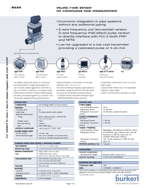
8030Page 1/12www.burkert–INLINE Flow sensor for continuous fl ow measurement• Economic integration in pipe systems without any additional piping• 2–wire frequency coil (sinusoidal) version 3–wire frequency (Hall effect) pulse version to directly interface with PLC’s (both PNP and NPN)• Can be upgraded to a low cost transmitter providing a calibrated pulse or 4–20 mAType 8034Flow indicator Wall or PanelType 8025Flow transmitter Wall or PanelType 80234–20 mA output moduleTyp 8623-2PI Flow–ControllerThe paddle–wheel fl ow sensor for continuous fl ow measurement is especially designed for use in neutral, slightly aggressive, solid free liq-uids. The sensor is made up of a compact fi tting (S030) and an electronic module (SE30) quickly and easily connected together by a Quarter–Turn.The Burkert designed fi tting system ensuressimple installation of the sensors into all pipe diameters from 1/4” to 2 1/2”.The sensor produces frequency signal (pulse or sinusoidal), proportional to the fl ow rate, which can easily be transmitted and processed by:– a Burkert remote transmitter/indicator (Type 8025/8034/8032 remote versions)– a transmitter module 8023 into a 4–20 mA output signal– a pulse divider module 8021 into adjustable frequency output signal– a batch controller 8600 mounted on a valveType 8030 can be combined with...Type 2712 (8630)ContinuousTopControl SystemPLCGeneral data Compatibility with all fi ttings S030 (see corresp. datasheet)MaterialsHousing, cover Cable plugMaterials wetted parts FittingPaddle–wheel Axis and bearing SealPCPA, brass electro–silver–plated Brass, Stainless Steel 1.4404/316L PVC, PP or PVDF PVDF CeramicFKM (EPDM option)Electrical connections Cable plug EN 175301–803Voltage supply cable Cross–sectionRecommended length1.5 mm² max.max. 10 m, shielded (for sinus sensor version)max. 50 m, shielded (for pulse sensor version)Complete device data (fitting + electronic module)Pipe diameter 1/4” to 2 1/2” (DN 6 to 65)Measuring range 1.0 ft/s to 32.8 ft/s (0.3 m/s to 10 m/s)Medium temperaturemax.122°F (50°C)with PVC fi tting 176°F (80°C)with PP fi tting212°F (100°C)with St.St., brass or PVDF fi tting Fluid pressure max.140 PSI (PN10)with plastic fi tting 230 PSI (PN16) with metal fi tting(PN40 on request, see 8030 HT datasheet)Viscosity 300 cSt. max.Accuracy Teach-InStandard K-factor ≤ ±0.5% of F.S.* (at 32.8 ft/s)≤ ±(0.5% of F.S. + 2.5% of Reading)*Linearity ≤ ±0.5% of F.S.* (at 32.8 ft/s)Repeatability 0.4% of Reading**Under reference conditions i.e. measuring fluid=water, ambient and water temperature=20°C, applying the minimum inlet and outlet pipe straights, matched inside pipe dimensions. F.S.=Full scale (10 m/s)Electrical data Power supplyCoil (sinusoidal) version Hall (pulse) versionHall (pulse) “low power” versionNone12–36 VDC12–36 VDC (via Burkert transmitter)Current consumptionwith sensorHall (pulse) versionHall (pulse) “low power” version< 30 mA < 0.8 mAOutput: Frequency Coil (sinusoidal) version Hall (pulse) versionHall (pulse) “low power” versionAlternating 0...10V, frequency: 0...300 Hz, Transis-tor NPN/PNP, open collector, max. 100 mA, frequency: 0...300 Hz; duty cycle 1/2Transistor NPN, open collector,max. 10 mA, frequency: 0...300 Hz; duty cycle 1/2Reversed polarity of DC ProtectedEnvironment Ambient temperature operating and storage 32 up to 140°F (0 up to +60°C)Relative humidity≤ 80%, non condensatedStandards and approvals Protection class IP65EMCEN 50081–1, 50082–2Page 2/128030Quarter-Turn TechnologyThe fl ow sensor 8030 is built up with an electronic module SE30associated to a fi tting S030 with integrated measurement paddle-wheel. This connection is made by means of a Quarter-Turn.In a 2 or 3–wire system, the signal can be displayed or processed directly. The output signal is provided via cable plug according to EN 175301-803.Principle of operationWhen liquid fl ows through the pipe, the paddle–wheel is set inrotation producing a measuring signal in the transducer. The frequency and amplitude are proportional to the fl ow.Three electronic module versions with frequency output are available:– with one sinus output. No external power supply is required. Can only be connected to the fl ow transmitter Type 8025 or the indicator 8034 with battery power supply in wall-mounted version.– with one pulse output (either NPN or PNP transistor output). An external power supply of 12–36 VDC is required.It is designed for connection to any system with open collector NPN or PNP frequency input.– with one pulse “low power” output (NPN transistor output). An external power supply of 12-36 VDC is required. Can only be connected to separate versions of fl ow transmitters Type 8025/8034, to 4–20 mA or calibrated frequency output modules Type 8021/8023/8600.DesignAccuracy diagram19234567810Flow velocity [m/s]246810-2-4-6-8-10Max. error [%]0.5%o .F .S .+2.5%o .R.0.5%o .F .S .F.S. = Full scale o.R. = of ReadingStandard calibration Teach-In calibrationBurkert Typical curve SE308030S030InstallationThe fl ow sensor 8030 can easily be installed into any Burkert INLINE fi tting system S030.be observed. According to pipe’s design,necessary distances can be bigger oruse a flaccuracy. For more information, please refer to EN ISO 5167–1.The fl ow rate sensor can be installed into either horizontal or verti-cal pipes. The suitable pipe size is selected using the diagram Flow/Velocity/DN. Pressure and temperature ratings must be re-spected according to the selected fi tting material. The fl ow sensor is not designed for gas fl ow measurement.Pressure / temperature chart (for plastic)16151413121110987654321-50-30-10+10+30+50+70+90+110+130APVDF PVDF (PN10)PVC (PN10)PP (PN10)Metal (PN16)PVC + PPA: Application range for complete device (fi tting + transmitter)Flow velocity [f/s][f/s]3.3 6.69.813.116.419.722.926.229.532.8-58 -22 +14 +50 +86 +122 +158 +194 +230 +266°F 232217.5203188.5174159.5145130.5116101.58772.55843.52914.50psiPage 3/128030Selection of fi tting / pipe size l/min DN 65DN 50DN 40DN 32DN 25DN 20DN 155000100010032120100.550.30.2500500.010.020.050.10.20.5125102050100200500m3/h 0.10.30.51235100.2m/sDN 08DN 0630200.30.5123510fpsgpm 2000100050020020100.50.20.10.0510050Dimensions [mm]Example:– S pecifi cation of nominal fl ow: 50 GPM – I deal fl ow velocity: 6...9 ft/s– F or these specifi cations, the diagram indicates apipe size of 1 1/2” (DN40)Flow rateFlow velocity32406644549HFlow sensor type 8030A fl ow sensor type 8030 consists of:– a sensor electronic module type SE30 – an Inline fi tting S030 (DN6 - DN 65) (Refer to corresponding data sheet)Ordering chart for sensor 8030S p e c i fi -c a t i o n sV o l t a g es u p p l yO u t p u tC o n n e c t o rI t e m n o .Coil (sinusoidal) version sensor(Can be used with Type 8025 or 8034 wall–mounted version with batteries)None Frequency Cable plug EN 175301–803423 912 C Hall (pulse) version sensor(Can be used with Type 8021 or Type 8600 and PLC’s)12–36 VDC Pulse PNP orNPN Cable plug EN 175301–803423 913 D Hall (pulse) “low power” version sensor (Only used with Type 8025 Remote Electronics, 8021, 8023, 8600, 8024)from associated transmitterPulse NPNCable plug EN 175301–803423 914 EOrifi ce H 1/4” (6) 95.55/16” (8) 95.51/2” (15)100.53/4” (20) 98.01” (25)98.01 1/4” (32)102.01 1/2” (40)105.52” (50)112.02 1/2” (65)112.02 1/2” (DN 65)2” (DN 50)1 1/2” (DN 40)1 1/4” (DN 32)1” (DN 25)3/4” (DN 20)1/2” (DN 15)5/16” (DN 08)1/4” (DN 06)Page 4/128030INLINE fitting dimensions [mm] Orifice DN P [mm] [mm]A [mm]D [mm]L [mm]1/2” (15)34.585.0NPT 1/2G 1/2Rc 1/217.016.015.03/4” (20)32.095.0NPT 3/4G 3/4Rc 3/418.317.016.31” (25)32.2105.0NPT 1 G 1Rc 1 18.023.518.01 1/4” (32)35.8120.0NPT 1 1/4G 1 1/4Rc 1 1/421.023.521.01 1/2” (40)39.6130.0NPT 1 1/2G 1 1/2Rc 1 1/220.023.519.02” (50)45.7150.0NPT 2G 2Rc224.027.524.0Internal threadNPT Stainless steel (316L - 1.4404) G or brass (CuZn39Pb2)RcExternal thread G Stainless steel (316L - 1.4404) or brass (CuZn39Pb2) or PVC (only DN6 and 8) or PVDF (only DN 8)External threadSMS1145Stainless steel (316L - 1.4404)ALDPALDPAPD** NPT, G, or RC according fi tting versionOrifi ce DN P A D L [mm][mm][mm][inch] [mm][mm]1/4” (6)29.590.0 1/4 or 1/2**-14.05/16” (8)29.590.01/2**M16x1.514.01/2” (15)34.584.0G 3/4-11.53/4” (20)32.094.0G 1-13.51” (25)32.2104.0G 1 1/4-14.01 1/4” (32)35.8119.0G 1 1/2-18.01 1/2” (40)39.6129.0-M 55 x 219.02” (50)45.7149.0-M 64 x 220.0Orifi ce DNP A D [mm][mm][mm]2532.0130 Rd40 x 1/6”4035.8164Rd60 x 1/6”5039.6173Rd70 x 1/6”Page 5/128030INLINE fitting dimensions [mm] Welding endsBS 4825 / ASME BPEStainless steel (316L - 1.4404) ISO 4200 SMS 3008DIN 11850 Rg2Tri-Clamp®BS 4825/ASME BPE*Stainless steel (316L - 1.4404) ISO (for pipe ISO4200)SMS 3017 / ISO 2852*DIN 32676*Available with internal surface finish Ra=0.8µmAPsDDPD 2D 1AOrifi ce DN P [mm] [mm]A [mm]Standard D [mm]s [mm]5/16” (08)29.5 90.0ISO 4200 -SMS 3008ASME BPEDIN 11850 Rg2---13.00--1.501/2” (15)34.5 84.0ISO 4200 21.30SMS 3008ASME BPEDIN 11850 Rg2 1.60--19.00--1.503/4” (20)32.034.5 94.0 84.0ISO 4200 26.90SMS 3008ASME BPEDIN 11850 Rg2 1.6020.0019.0523.00 1.001.651.501” (25)32.232.0104.0 94.0ISO 4200 33.70SMS 3008BS 4825/ASME BPEDIN 11850 Rg2 2.0025.0025.4029.00 1.201.651.501 1/4” (32)35.832.2119.0104.0ISO 4200 42.40SMS 3008BS 4825/ASME BPEDIN 11850 Rg2 2.00-32.0035.00-1.601.501 1/2” (40)39.635.8129.0119.0ISO 4200 48.30SMS 3008BS 4825/ASME BPEDIN 11850 Rg2 2.0038.0038.1041.00-1.201.651.502” (50)45.739.6149.0128.0ISO 4200 60.30SMS 3008BS 4825/ASME BPEDIN 11850 Rg2 2.0051.0050.8053.00-1.201.651.502 1/2” (65)45.7147.0ISO 4200 -SMS 3008BS 4825/ASME BPEDIN 11850 Rg2-63.5063.50--1.601.65-Orifi ce DN P [mm] [mm]A [mm]StandardD2[mm]D1[mm]D [mm]5/16” (08)- -ISO (for pipe ISO 4200)SMS 3017/ISO 2852ASME BPE DIN 32676---10.00---27.5---34.01/2” (15)34.5130.0-ISO (for pipe ISO 4200)SMS 3017/ISO 2852ASME BPE DIN 3267618.10--16.0027.5--27.534.0--34.03/4” (20)32.034.5 150.0ISO (for pipe ISO 4200)SMS 3017/ISO 2852ASME BPE DIN 3267623.70-15.7522.0043.5--27.550.5-25.034.01” (25)32.232.0160.0129.0ISO (for pipe ISO 4200)SMS 3017/ISO 2852BS 4825/ASME BPE DIN 3267629.7022.6022.1026.0043.543.543.543.550.550.550.550.51 1/4” (32)35.8-180.0-ISO (for pipe ISO 4200)SMS 3017/ISO 2852ASME BPE DIN 3267638.40---43.5---50.5---1 1/2” (40)39.635.8200.0161.0ISO (for pipe ISO 4200)SMS 3017/ISO 2852BS 4825/ASME BPE DIN 3267644.3035.6034.8038.0056.543.543.543.564.050.550.550.52” (50)45.739.6230.0192.0ISO (for pipe ISO 4200)SMS 3017/ISO 2852BS 4825/ASME BPE DIN 3267655.1048.6047.5050.0070.556.556.556.577.564.064.064.02 1/2” (65)45.7216.0SMS 3017/ISO 2852BS 4825/ASME BPE DIN 3267660.3060.20-70.570.5-77.577.5-Page 6/128030INLINE fitting dimensions [mm] DN[m m ]J I SN O R MOrifi ce P AL Z D2 D1 D1/2” (15) 34.5 130.0 152.0 DIN 23.5 4x14.0 45.0 65.0 95.0 ANSI 4x15.8 34.9 60.3 89.0 JIS 4x15.0 51.0 70.0 95.03/4” (20) 32.0 150.0 178.0 DIN 28.5 4x14.0 58.0 75.0 95.0 ANSI 4x15.8 42.9 69.8 89.0 JIS 4x15.0 56.0 75.0 95.01” (25) 32.2 160.0 216.0 DIN 28.5 4x14.0 68.0 85.0 95.0 ANSI 4x15.8 50.8 79.4 89.0 JIS 4x19.0 67.0 90.0 95.01 1/4” (32) 35.8 180.0 229.0 DIN 31.0 4x18.0 78.0 100.0 95.0 ANSI 4x15.8 63.5 88.9 89.0 JIS 4x19.0 76.0 100.0 95.01 1/2” (40) 39.6 200.0 241.0 DIN 36.0 4x18.0 88.0 110.0 95.0 ANSI 4x15.8 73.0 98.4 89.0 JIS 4x19.0 81.0 105.0 95.02” (50) 45.7 230.0 267.0 DIN 41.0 4x18.0 102.0 125.0 95.0 ANSI 4x19.0 92.1 120.6 89.0 JIS 4x19.0 96.0 120.0 95.0ALD 2D 1DZP[mm] [m m ][mm] [mm] [mm] [mm] [mm] [mm] FlangeANSI B16-5-1988 Stainless steel (316L - 1.4404) DIN 2633 (ISO PN16)JIS 10KD I N /A N S I* Available only in PVCTrue union nutwith solvent or fusion spigot PVC, PP, PVDFAA1A2PDD 1Orifi ce P D1 A D A2 A1 ADN [mm] DIN ANSI JIS (DIN) (ANSI) (JIS) 291/4” (08)* 29.5 122 - - 12 - - 90 921/2” (15) 34.5 43 128 130.0 129 20 21.3 18.40 90 96323/4” (20) 32.0 53 144 145.6 145 25 26.7 26.45 100 1061” (25) 32.2 60 160 161.4 161 32 33.4 32.55 110 1162) 351 1/4” (32) 35.8 74 168 170.0 169 40 42.2 38.60 110 116 1 1/2” (40) 39.6 83 188 190.2 190 50 48.3 48.70 120 127452” (50) 45.7 103 212 213.6 213 63 60.3 60.80 130 136Solvent or fusion spigot PVC, PP, PVDFPH DLAOrifi ce D H A L P DN PVC PP PVC PP PVDF PVDF [mm][mm] [mm] [mm] [mm] [mm] [mm] [mm] 5 0 15 20 17.5 90 85 16.5 14 34.50 0 20 25 17.5 100 92 20.0 16 32.00 0 25 32 21.5 110 95 23.0 18 32.25 0 32 40 27.5 110 100 27.5 20 35.80 0 40 50 31.5 120 106 30.0 23 39.60 0 50 63 39.5 130 110 37.0 27 45.78030 Combination with other devices (via plug-in contacts) - Operation and displayA fl ow sensor Type 8030 with adjustable frequency outputconsists of:- a sensor electronic module Type SE30 (Hall or Hall “Low power” sensor versions)- an Inline fi tting S030 (DN6 - DN 65) (Refer to corresponding data sheet)- a calibrated pulse output module Type 8021This sensor requires an external power supply of 12–30 VDC. It isdesigned for connection to any system with open collector NPN orPNP frequency input .The fl ow sensor 8030 can be upgraded into a transmitter with a calibrated pulse output or a 4–20 mA output. To obtain such a transmitter, an additional IP65 housing is plugged on the sensor instead of the cable plug EN 175301-803.Type 8021 calibrated frequency output moduleThe operation is specifi ed accordingto the following level:Parameter defi nition- K-factor- D multiplier Rotaryswitchesfor K-factorselectionRotary switchesfor D multiplierselectionType 8023, 4–20 mA output moduleThe operation is specifi ed accordingto two levels:Indication in operating mode-FlowParameter defi nition- K-factor- Time unit- 4-20 mA measuring range* The device works without the control unit. The control unit only enables to performparameter defi nition.4-20 mA module (8023) withcontrol unit (1077)*AmendvaluesConfi rmvaluesSpecifi-cationsPowersupplyConnectorItemno.Calibrated pulse output module type 802112–30 VDC 1 cable gland418 895 P4–20 mA output module type 802312–24 VDC 1 cable gland130 428 V Programming module type 1077–3 for the 4–20 mA output module type 802312–24 VDC None130 446 X Interconnection possibilities with the sensor Type 8030Type 8600 –BatchcontrollerSpecific data 8030 with calibrated frequency outputSupply voltage12–30 VDCOutput signal transistor NPN or PNPopen collector max. 100 mAAccuracy0.1 %Material of 8021 housing PASpecific data 8030 with 4-20 mA outputSupply voltage12–24 VDCOutput signal4–20 mALoad max. 500 Ω at 12V;max. 1000 Ω at 24VAccuracy± 2 %Material of 8023 housing PAType 8030 –with Hall sensor(pulse signal)Type 8021 -Calibratedfrequencyoutput mo-duleType 8025 –Flow transmitterwall versionwith batteryType 8030 –with Coil sensor(sinus signal)Type 8034 –Flow indicatorpanel versionwith batteryA fl ow sensor Type 8030 with 4-20 mA output consists of:- a sensor electronic module Type SE30 (Hall “Low power” sensor version)- an Inline fi tting S030 (DN6 - DN 65) (Refer to corresponding data sheet)- a 4–20 mA output module Type 8023- a programming module Type 1077–3 for the Type 8023This sensor runs in 2–wire systems and requires an external powersupply of 12–24 VDC.Type 8021 -Calibratedfrequencyoutput mo-duleType 8025 –Flow transmitter/Batchpanel or wall versionType 8030 –with Hall sensor “Low power”(pulse signal)Type 8034 –Flow indicatorpanel version withbatteryType 8032 –Flow Sensorremote versionType 8023 –4-20 mAoutputmoduleOrdering chart for accessories for sensor type 8030 (to be ordered separately)Page 7/12Page 8/128030INLINE fi tting part numbersS t a n d a r d s1/4” (D N 6)5/16”(D N 8)1/2”(D N 15)3/4”(D N 20)1” (D N 25)1 1/4”(D N 32)1 1/2”(D N 40)2”(D N 50)2 1/2”(D N 65)1) external thread 1/4“2) external thread 1/2"3) EPDM Seal4) DN20 only available in ASME BPEItem no. / Orifi ceBrass - with PVDF paddle-wheel - Temperature max. 212°F, 230 PSI (PN16)Internal thread NPT--- 423 987423 988 423 989 423 990 423 991 --- FKM --- --- 423 986 G--- --- --- 423 980 423 981 423 982 424 983 424 984 424 985 ---Rc (ISO7) --- --- --- 423 992 423 993 423 994 424 995 424 996 424 997 ---External thread M 449 182 FKM NPT --- --- ------ --- --- --- --- ---55 G552 5571) 552 5272)423 998444 023 423 999 424 000 424 001 424 002 424 003 ---Rc (ISO7)--- --- 448 668 --------- --- ---------Stainless steel - with PVDF paddle-wheel - Temperature max. 212°F, 230 PSI (PN16)Internal thread --424 013424 014 FKM NPT --- --- --- 424 010 424 011 424 012 424 015 --- G --- --- --- 424 004 424 005 424 006 424 007 424 008 424 009 --- Rc (ISO7) --- --- --- 424 016 424 017 424 018 424 019 424 020 424 021 ---External thread FKM NPT --- --- 449 050 --- --- ------ --- --- ---55 G 552 7331) 552 5592)444 029 424 022 424 023 424 024 424 025 424 026 424 027 --- Rc (ISO7) --- --- 448 669 --- --- --- --- --- --- --- EPDM SMS 1145 --- --- --- --- --- 443 306--- 443 307 443 308 ---Weld ends FKM ISO 4200 --- --- 552 8453)424 028 424 029 424 030 424 031 424 032 424 033 ---EP EPDM BS4825 / ASME BPE --- --- --- --- 443 3694) 443 370 443 371 443 372 443 373 443 374 SMS 3008 --- --- --- --- --- 443 298 --- 443 299 443 300 443 301 DIN 11850 Rg2 --- --- 551 788 551 789 551 790 551 791 --- 551 792 551 793 ---Tri-Clamp® FKM ISO (for pipe ISO4200) --- --- --- 424 034 424 035 424 036 424 037 424 038 424 039 ---EP EPDM BS4825/ASME BPE --- --- --- --- 443 395 443 396 --- 443 397 443 398 443 399 SMS3017/ISO2852 --- --- --- --- --- 443 302 --- 443 303 443 304 443 305 BS4825/ASME BPE* --- --- --- --- 443 400 443 717 --- 443 718 443 719 443 720 SMS3017/ISO2852*--- --- --- --- --- 443 387 --- 443 388 443 389 443 390 DIN 32676 --- --- 551 794 551 795 551 796 551 797 --- 551 798 551 799 ---Flange FKM ANSI B16-5-1988 --- --- --- 424 046 424 047 424 048 424 049 424 050 424 051 --- DIN 2633 --- --- --- 424 040 424 041 424 042 424 043 424 044 424 045 ---JIS 10K---------430 108 430 109 430 110 430 111 430 112 430 113---PVC - with PVDF paddle-wheel - Temperature max. 122°F, 140 PSI (PN10)True union - solvent spigot FK FKM North America version North America version 423 951423 952 423 953 423 954 423 955 --- --- --- 423 950 ISO --- 444 022 423 938 423 939 423 940 423 941 423 942 423 943 --- Standard JIS --- --- 429 072 429 073 429 074 429 075 429 076 429 077 ---Solvent ends FKM ISO --- --- 423 944423 945 423 946 423 947 423 948 423 949 ---55External thread FKM G 552 5602) 444 0252)--- --- --- --- --- --- ---True union without spigot without spigot FKM --- --- 430 734 430 735 430 736 430 737 430 738 430 739 --- EPDM --- --- 430 740 430 741430 742430 743430 744430 745---True union - solvent spigot True union - solvent spigot FKM--- --- 423 956 423 957 423 959 ---got ISO 423 958 423 960 423 961 ISO 423 964 423 966 Solvent ends FKM --- --- 423 962 423 963 423 965 423 967---True union - solvent spigot FKM --- --- 423 969 423 971 ---got ISO 423 968 423 970 423 972 423 973 True union - solvent spigot ISO 423 976 423 978 Solvent ends FKM --- --- 423 974 423 975 423 977 423 979---External thread FKM G---444 0282)--- --- --- --- --- ------p o r tc o n n e c t i o nS e a lSpecifi cationS t a n d a r d sp o r tc o n n e c t i o nS e a lSpecifi cationPP (metric pipe only)- with PVDF paddle-wheel - Temperature max. 176°F, 140 PSI (PN10)PVDF (metric pipe only)- with PVDF paddle-wheel - Temperature max. 212°F, 140 PSI (PN10)1/4”(D N 6)5/16”(D N 8)1/2”(D N 15)3/4”(D N 20)1” (D N 25)1 1/4”(D N 32)1 1/2”(D N 40)2”(D N 50)2 1/2”(D N 65)Item no. / Orifi ce * internal surface fi nish Ra = 0.8 µmPage 9/1280308030 SystemsPVC Body with True–Union Ends, PVDF Paddle, Ceramic Shaft and Bearings.Max operating is 140psi and 122°F.FKM is standard seal material.1-33fps fl ow range capability 8030 with PNP or NPN Hall Signaloutput (frequency output) 0-200HZ1/2” Flow Meter System Part # US084023/4” Flow Meter System Part # US084011” Flow Meter System Part # US084001 1/4” Flow Meter System Part # US083991 1/2” Flow Meter System Part # US083982” Flow MeterSystem Part # US08397Brass Body with NPT Ends, PVDF Paddle, Ceramic Shaft and Bearings.Max operating is 230psi and 212°F.FKM is standard seal material.1-33fps fl ow range capability 8030 with PNP or NPN Hall Signaloutput (frequency output) 0-200HZ1/2” Flow Meter System Part # 424 468 Y 3/4” Flow Meter System Part # 424 469 Z 1” Flow Meter System Part # 424 470 W 1 1/4” Flow Meter System Part # 424 471 K 1 1/2” Flow Meter System Part # 424 472 L 2” Flow MeterSystem Part # 424 473 MPVDF Body with True–Union Fusion Spigot, PVDF Paddle, Ceramic Shaft and Bearings.Max operating is 140psi and 122°F.FKM is standard seal material.1-33fps fl ow range capability 8030 with PNP or NPN Hall Signaloutput (frequency output) 0-200HZ20mm Flow Meter System Part # US0837225mm Flow Meter System Part # US0837132mm Flow Meter System Part # US0837040mm Flow Meter System Part # US0836950mm Flow Meter System Part # US0836863mm Flow MeterSystem Part # US08367SS Body with NPT Ends, PVDF Paddle, Ceramic Shaft and Bearings.Max operating is 230psi and 212°F.FKM is standard seal material.1-33fps fl ow range capability 8030 with PNP or NPN Hall Signaloutput (frequency output) 0-200HZ1/2” Flow Meter System Part # 424 522 E 3/4” Flow Meter System Part # 424 523 F 1” Flow Meter System Part # 424 524 G 1 1/4” Flow Meter System Part # 424 525 H 1 1/2” Flow Meter System Part # 424 526 A 2” Flow MeterSystem Part # 424 527 BPVC Flow Sensor with Frequency Output 1/2” - 2”Brass Flow Sensor with Frequency Output 1/2” - 2”PVDF Flow Sensor with Frequency Output 20mm to 63mmStainless Steel Flow Sensor with Frequency Output 1/2” - 2”80308023 SystemsPVC Body with True–Union Ends,PVDF Paddle, Ceramic Shaft and Bearings. Max operating is 140psi and 122°F.FKM is standard seal material.1-33fps fl ow range capability System part number below will include fi tting, electronic sensor and transmitter (one programmer is neded for any number of transmitters selected below)1/2” Blind 4-20mA fl ow transmitter System Part # US08470 3/4” Blind 4-20mA fl ow transmitter System Part # US08469 1” Blind 4-20mA fl ow transmitter System Part # US08468 1 1/4” Blind 4-20mA fl ow transmitter System Part # US08467 1 1/2” Blind 4-20mA fl ow transmitter System Part # US08466 2” Blind 4-20mA fl ow transmitter System Part # US08465 Programmer (needed for any multiplenumber of fl ow meters purchased above)Part #130446XBrass Body with NPT Ends,PVDF Paddle, Ceramic Shaft and Bearings. Max operating is 230psi and 212°F.FKM is standard seal material.1-33fps fl ow range capability System part number below will include fi tting, electronic sensor and transmitter (one programmer is neded for any number of transmitters selected below)1/2” Blind 4-20mA fl ow transmitter System Part # US08414 3/4” Blind 4-20mA fl ow transmitter System Part # US08413 1” Blind 4-20mA fl ow transmitter System Part # US08412 1 1/4” Blind 4-20mA fl ow transmitter System Part # US08411 1 1/2” Blind 4-20mA fl ow transmitter System Part # US08410 2” Blind 4-20mA fl ow transmitter System Part # US08409 Programmer (needed for any multiplenumber of fl ow meters purchased above)Part #130446XSS Body with NPT Ends,PVDF Paddle, Ceramic Shaft and Bearings. Max operating is 230psi and 212°F.FKM is standard seal material.1-33fps fl ow range capability System part number below will include fi tting, electronic sensor and transmitter (one programmer is neded for any number of transmitters selected below)1/2” Blind 4-20mA fl ow transmitter System Part # US08396 3/4” Blind 4-20mA fl ow transmitter System Part # US08395 1” Blind 4-20mA fl ow transmitter System Part # US08394 1 1/4” Blind 4-20mA fl ow transmitter System Part # US08393 1 1/2” Blind 4-20mA fl ow transmitter System Part # US08392 2” Blind 4-20mA fl ow transmitter System Part # US08391Programmer (needed for any multiple number of fl ow meters purchased above)Part #130446XBrass 4-20 mA Blind Two Wire Flow Transmitters 1/2” - 2”Stainless 4-20 mA Blind Two Wire Flow Transmitters 1/2” - 2”PVC 4-20 mA Blind Two Wire Flow Transmitters 1/2” - 2”Page 10/128030 8023 Systems (continued)PVDF Body with True–Union Fusion Spigot Ends, PVDF Paddle, Ceramic Shaft and Bear-ings. Max operating is 140psi and 212°F. FKM is standard seal material.1-33fps fl ow range capability System part number below will include fi tting, electronic sensor and transmitter (one programmer is neded for any number of transmitters selected below)20mm Blind 4-20mA fl ow transmitter System Part # US08390 25mm Blind 4-20mA fl ow transmitter System Part # US08389 32mm Blind 4-20mA fl ow transmitter System Part # US08388 40mm Blind 4-20mA fl ow transmitter System Part # US08387 50mm Blind 4-20mA fl ow transmitter System Part # US08386 63mm Blind 4-20mA fl ow transmitter System Part # US08385Programmer (needed for any multiple number of fl ow meters purchased above)Part #130446XPVDF 4-20 mA Blind Two Wire Flow Transmitters 20mm to 63mmPage 11/128030In case of special application conditions, We reserve the right to make technical 0602/3_US-en please consult for advice. changes without notice.Page 12/12。
基于STM32单片机的微电网模拟系统设计
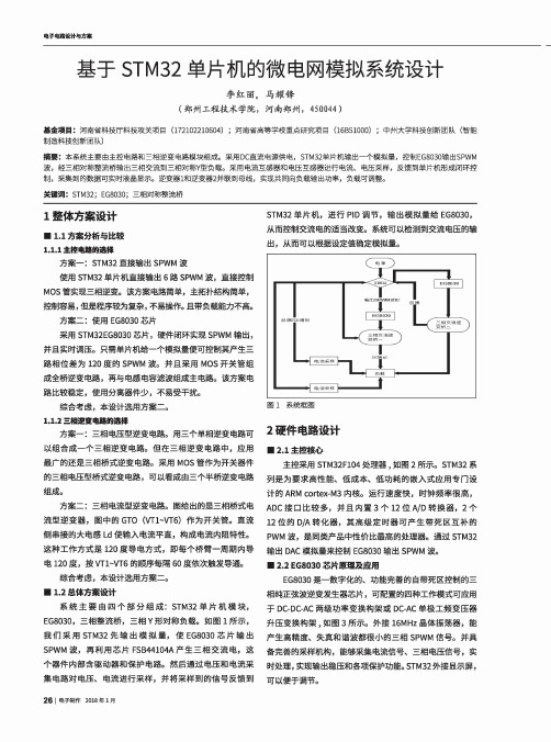
电子电路设计与方案基于STM32单片机的微电网模拟系统设计李红丽,马耀锋(郑州工程技术学院,河南郑州,450044 )基金项目:河南省科技厅科技攻关项目(172102210604);河南省高等学校重点研究项目(16B51000);中州大学科技创新团队(智能 制造科技创新团队)摘要:本系统主要由主控电路和三相逆变电路模块组成。
采用DC直流电源供电,STM32单片机输出一个模拟量,控制EG8030输出SPWM 波,经三相对称整流桥输出三相交流到三相对称Y型负载。
采用电流互感器和电压互感器进行电流、电压采样,反馈到单片机形成闭环控 制,采集到的数据可实时液晶显示。
逆变器1和逆变器2并联到母线,实现共同向负载输出功率,负载可调整。
关键词:STM32; EG8030;三相对称整流桥1整体方案设计■ 1.1方案分析与比较1.1.1主控桃的逸择方案一 :STM32直接输出SPWM波使用STM32单片机直接输出6路SPWM波,直接控制 MOS管实现三相逆变。
该方案电路简单,主拓扑结构简单,控制容易,但是程序较为复杂,不易操作。
且带负载能力不高。
方案二:使用EG8030芯片采用STM32EG8030芯片,硬件闭环实现SPWM输出,并且实时调压。
只需单片机给一个模拟量便可控制其产生三 路相位差为120度的SPWM波。
并且采用MOS开关管组 成全桥逆变电路,再与电感电容滤波组成主电路。
该方案电 路比较稳定,使用分离器件少,不易受干扰。
综合考虑,本设计选用方案二〇1.1.2三相逆变电路的挪方案一:三相电压型逆变电路。
用三个单相逆变电路可 以组合成一个三相逆变电路。
但在三相逆变电路中,应用 最广的还是三相桥式逆变电路。
采用MOS管作为开关器件 的三相电压型桥式逆变电路,可以看成由三个半桥逆变电路 组成。
方案二:三相电流型逆变电路。
图给出的是三相桥式电 流型逆变器,图中的GTO(VT1~VT6)作为开关管。
直流 侧串接的大电感Ld使输入电流平直,构成电流内阻特性。
EG301_datasheet
ELECTRONIC GIANT EG301用户手册 滚动码编码芯片版本变更历史目录1. 特性 (3)2. 描述 (3)3. 应用领域 (3)4. 引脚 (4)4.1 引脚定义 (4)4.2 引脚描述 (4)5. 结构框图 (5)6. EG301工作原理 (5)7. 对EG301编程 (5)8. 典型应用电路 (7)9. 电气特性 (7)10. 封装尺寸 (8)1. 特性⏹工作电压:3.5V - 13.0V⏹最大静态电流:<1uA⏹内部集成电源管理⏹自动关闭⏹片上EEPROM⏹可编程28位序列号⏹可编程64位加密密钥⏹密钥不可读⏹每次发送惟一的滚动编码⏹ 4 路按钮输入,15种按键组合⏹按键集成内部下拉电阻⏹滚动编码波特率可选⏹电池低电压指示⏹非易失性同步数据⏹封装:SOP82. 描述EG301是一款滚动码编码芯片,适用于遥控无钥门禁(RKE)系统。
EG301具有高安全性、封装尺寸小、超低待机功耗等特点。
芯片内部采用64位加密技术,无法破解。
小于1uA的待机电流,保证电池更长的工作时间。
内部集成EEPROM,可以灵活配置芯片不同的工作状态,EEPROM数据能够保存10年以上。
3. 应用领域⏹汽车RKE系统⏹汽车报警系统⏹汽车防盗锁止器⏹大门和车库开门器⏹身份识别系统⏹防盗自动报警系统4. 引脚4.1 引脚定义4.2 引脚描述5. 结构框图S0 S1 S2 S3VDD /LEDPWM VSS6. EG301工作原理当检测到有按钮被按下时,EG301将被唤醒,并延时大约15 ms 以等待按钮抖动平息。
加密同步计数值、识别码和按钮信息以形成滚动码。
每次新的按键都会产生新的滚动码,即便是再次按下同一个按钮也是如此。
发送的编码字在超过64K次传输中都不会重复。
保持按键不放时,滚动码会重复发送相同的编码信息,直到有新的按键按下。
当同时按下多个按键时,再松开其中某个按键时,滚动码编码信息不会改变。
只有按下其他按键或松开所有按键再重新按下按键时,滚动码编码信息才会改变。
EG1182 芯片数据手册说明书

ELECTRONIC GIANTEG1182芯片数据手册48V电池供电系统降压型开关电源芯片版本变更记录版本号日期描述V1.0 2013年04月12日EG1182数据手册初稿目录1. 特点 (4)2. 描述 (4)3. 应用领域 (4)4. 引脚 (5)4.1. 引脚定义 (5)4.2. 引脚描述 (5)5. 结构框图 (6)6. 典型应用电路 (6)7. 电气特性 (8)7.1 极限参数 (8)7.2 典型参数 (9)8. 应用设计 (10)8.1Vin输入电容 (10)8.2Vcc储能电容 (10)8.3启动过程 (10)8.4振荡器CT电容的开关频率计算 (10)8.5输出峰值限流 (10)8.6输出短路保护 (11)8.7输出电感 (11)8.8续流二极管 (11)8.9输出电容 (11)8.10输出电压调节端(ADJ)设置 (11)9. 封装尺寸 (12)9.1 DIP8封装尺寸 (12)9.2 SOP8 - EP封装尺寸 (13)EG1182芯片数据手册V1.01. 特点⏹宽电压输入电压范围:20V至60V⏹外接元件少,无需外围补偿网络能达到稳定工作⏹保护功能:●过流保护●短路保护⏹外接一个电容可设置工作频率(10KHz-100KHz)⏹UVLO欠压锁定功能:●Vcc引脚端的开启电压6.5V●Vcc引脚端的关闭电压3.5V●UVLO迟滞电压为3V⏹无需外接启动电阻⏹内置高压功率管⏹可外部扩展高压功率管应用于输出大电流场合⏹外接一个小功率电阻可控制峰值电流⏹逐周限流控制⏹封装形式:DIP-8和SO-82. 描述EG1182是一款48V电池供电降压型DC-DC电源管理芯片,内部集成基准电源、振荡器、误差放大器、过热保护、限流保护、短路保护等功能,非常适合高压60V场合应用。
EG1182应用在电动车48V控制器系统中,能直接替代LM317、LM7815或电阻型降压线性稳压器,具有高效率,高可靠性等特性,能大大降低整体控制器的温度,使整个系统能够更可靠工作。
EG4002_datasheet
ELECTRONIC GIANT EG4002芯片数据手册红外热释电专用芯片红外热释电专用芯片版本变更记录红外热释电专用芯片目录1. 特点 (4)2. 描述 (4)3. 应用领域 (4)4. 引脚 (5)4.1. 引脚定义 (5)4.2. 引脚描述 (5)5. 结构框图 (6)6. 典型应用电路 (6)6.1 EG4002典型应用电路图 (6)6.2 EG4002控制继电器应用电路图 (7)6.3 EG4002可重复触发+光敏电阻应用电路图 (7)7. 电气特性 (8)7.1 极限参数 (8)7.2 典型参数 (9)8. 应用设计 (10)8.1振荡器工作频率计算 (10)8.2触发延时时间定时器和触发封锁时间定时器 (10)8.3A端重复和不可重复触发功能 (11)8.4Vc触发禁止端 (12)8.5第一级运放增益设定 (12)9. 封装尺寸 (13)9.1 DIP8封装尺寸 (13)9.2 SOP8封装尺寸 (13)红外热释电专用芯片EG4002芯片数据手册V1.21. 特点⏹8引脚数红外热释电专用芯片,外围电路简单,成本低⏹静态功耗小,3V工作电源时功耗小于45uA, 5V工作电源时功耗小于75uA,非常适合电池供电系统应用⏹高输入阻抗运算放大器,可与多种传感器匹配,进行信号与处理⏹双向鉴幅器,可有效抑制干扰⏹内置参考电压,供内部比较器和运放的参考电压⏹内设延时时间定时器和封锁时间定时器,改变振荡器频率即可设定定时延时时间⏹外围元器件少,只需配置第一级运放的增益和振荡器的RC器件即能可靠工作⏹工作电源+3V~+6V⏹封装形式: SOP8和DIP82. 描述EG4002是一款专为热释电红外传感器信号放大及处理输出的数模混合专用芯片,内部集成了运算放大器、双门限电压比较器、参考电压源、延时时间定时器和封锁时间定时器及状态控制器等,专用于防盗报警系统、人体门控制装置、照明控制开关等场合。
EG4002电源工作电压为+3V~+6V,采用 COMS工艺数模混合相结合的集成电路,8个引脚数封装设计,降低了外围电路元件数和整体成本,节省了PCB板空间。
EG1130 芯片数据手册说明书

版本变更记录版本号日期描述V1.0 2019年12月02日EG1130数据手册初稿目录1. 特性 (1)2. 描述 (1)3. 应用领域 (1)4. 引脚 (2)4.1 引脚定义 (2)4.2 引脚描述 (2)5. 结构框图 (3)6. 典型应用电路 (3)7. 电气特性 (4)7.1 极限参数 (4)7.2 典型参数 (4)8. 应用设计 (5)8.1 PCB板布局 (5)8.2 输出电感 (5)8.3 输出电容 (5)8.4 输出电压设置 (5)9. 封装尺寸 (6)9.1 SOT23-6封装尺寸 (6)EG1130芯片数据手册V1.01. 特性⏹宽电压输入范围2V-24V⏹输出电压可达28V⏹固定开关频率1.2MHz⏹集成80mΩ功率MOS管⏹内置4A限流保护⏹内置补偿电路⏹内置软启动电路⏹输出电压灵活可调⏹过热保护⏹封装形式:SOT23-62. 描述EG1130是一款电流模式升压型DC-DC电源管理芯片,内置欠压锁定、限流保护、热保护、功率管等功能。
3. 应用领域⏹摄像头电源⏹电池充电器⏹车充电源⏹液晶电视电源4. 引脚4.1 引脚定义图4-1. EG1130管脚定义4.2 引脚描述5. 结构框图FBLXGNDEN图5-1. EG1130结构框图6. 典型应用电路图6-1. EG1130 典型应用电路图7. 电气特性7.1 极限参数注:超出所列的极限参数可能导致芯片内部永久性损坏,在极限的条件长时间运行会影响芯片的可靠性。
7.2 典型参数8. 应用设计8.1 PCB 板布局输入电容尽量靠近芯片管脚;大电流路径(GND 、VIN 、LX )走线尽量宽、短连接。
8.2 输出电感电感的选取可根据下式公式:LL =VVVV VV ×(VVVVVVVV +VVVV −VVVV VV )(VVVVVVVV +VVVV )×FFFF ×II II VV II IIII II式中:Vin 是输入电压;Vout 是输出电压;Vd 是续流二极管的压差;Fs 是PWM 工作频率;Iripple 是电感中电流纹波的峰峰值。
EG8030中文版说明书
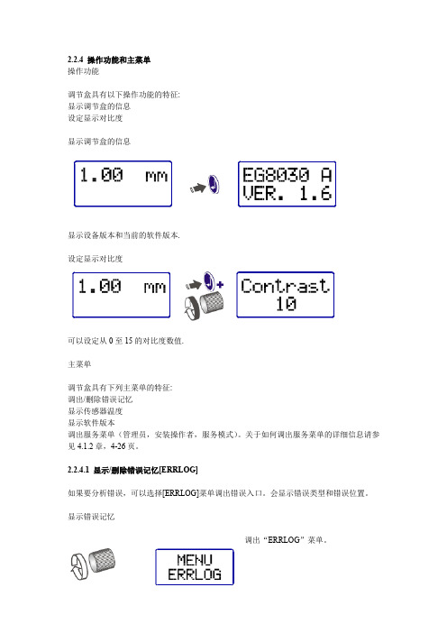
2.2.4 操作功能和主菜单操作功能调节盒具有以下操作功能的特征:显示调节盒的信息设定显示对比度显示调节盒的信息显示设备版本和当前的软件版本.设定显示对比度可以设定从0至15的对比度数值.主菜单调节盒具有下列主菜单的特征:调出/删除错误记忆显示传感器温度显示软件版本调出服务菜单(管理员,安装操作者,服务模式)。
关于如何调出服务菜单的详细信息请参见4.1.2章,4-26页。
2.2.4.1 显示/删除错误记忆[ERRLOG]如果要分析错误,可以选择[ERRLOG]菜单调出错误入口。
会显示错误类型和错误位置。
显示错误记忆调出“ERRLOG”菜单。
调出错误入口。
如果没有错误则如图所示。
错误入口请见6.1.3章,6-68页。
取消此项功能调节盒会自动切换回到上一层菜单层或者关闭主菜单。
删除错误记忆调出错误入口。
选择删除错误记忆[Delerr?]来删除错误列表。
删除错误记忆当错误被更正之后错误记忆可以被删除。
只有当出现问题的错误被更正之后,现存的错误入口才可以被删除。
删除之后调节盒切换回ERRLOG菜单。
2.2.4.2 显示传感器温度[Temper.]只有集成了温度探测器件的传感器才支持传感器温度探测。
调出“Temper.”菜单。
显示传感器温度。
如果传感器支持温度检测则会显示当前温度。
取消此项功能。
然后调节盒会启动切换回上一层菜单层或者关闭主菜单。
没有配备温度检测的Lasermatic传感器如果传感器没有配备温度探测器件,会显示断线。
如果出现下列情况也会显示断线:传感器存在缺陷或者传输出现问题。
2.2.4.3 显示软件版本[Version]调出“Version”菜单。
显示设备信息。
会显示调节盒的类型,特定版本号和当前的软件版本号。
取消此项功能。
然后调节盒会启动切换回到上一层菜单层或者关闭主菜单。
2.5 接口,界面图. 2-5 接口,调节盒(背面)1 A 条状接口(I/O 界面)2 D 接口(BNC,传感器连接)3 B 条状接口(供电)4 E 条状接口* (CANopen field总线)5 C 条状接口(CANprecitec)6 PE 连接* 只有使用EG8030C,版本C才可以启用CANopen field总线接口。
EG8010芯片数据手册说明书
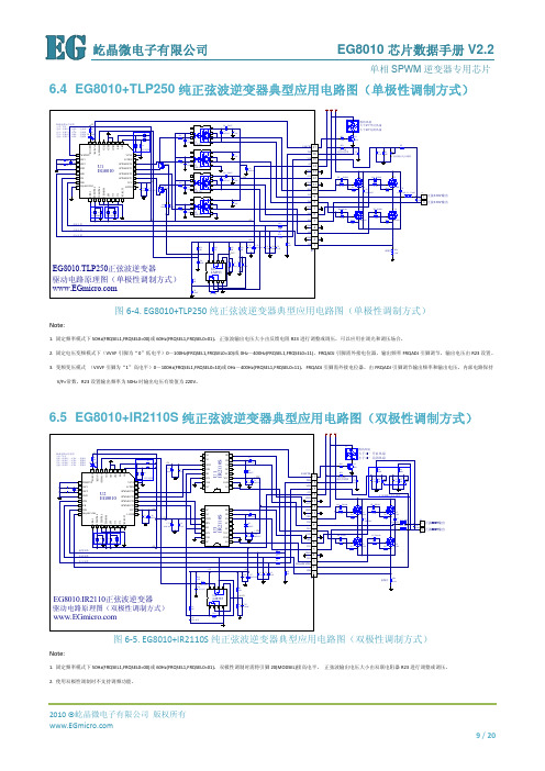
6.4 EG8010+TLP250纯正弦波逆变器典型应用电路图(单极性调制方式)220V输出220V输出图6‐4. EG8010+TLP250纯正弦波逆变器典型应用电路图(单极性调制方式)Note:1. 固定频率模式下50Hz(FRQSEL1,FRQSEL0=00)或60Hz(FRQSEL1,FRQSEL0=01),正弦波输出电压大小由反馈电阻R23进行调整或调压,可以应用在调光和调压场合。
2. 固定电压变频模式下(VVVF引脚为“0”低电平)0~100Hz(FRQSEL1,FRQSEL0=10)或0Hz~400Hz(FRQSEL1,FRQSEL0=11),FRQADJ引脚需外接电位器,输出频率FRQADJ引脚调节,输出电压由R23设置。
3. 变频变压模式 (VVVF引脚为“1”高电平)0~100Hz(FRQSEL1,FRQSEL0=10)或0Hz~400Hz(FRQSEL1,FRQSEL0=11),FRQADJ引脚需外接电位器,由FRQADJ引脚调节输出频率和输出电压,内部电路保持V/F=常数,R23设置输出频率为50Hz时输出电压有效值为220V。
6.5 EG8010+IR2110S纯正弦波逆变器典型应用电路图(双极性调制方式)图6‐5. EG8010+IR2110S纯正弦波逆变器典型应用电路图(双极性调制方式)Note:1. 固定频率模式下50Hz(FRQSEL1,FRQSEL0=00)或60Hz(FRQSEL1,FRQSEL0=01),双极性调制时需将引脚20(MODSEL)接高电平, 正弦波输出电压大小由双联电阻器R23进行调整或调压。
2. 使用双极性调制时不支持调频功能。
6.6 EG8010+IR2110S纯正弦波逆变器典型应用电路图(工频变压器)220V输出220V输出图6‐6. EG8010+IR2110S工频变压器正弦波逆变器典型应用电路图Note:1. T1需使用工频变压器,工频变压器次级需外接高压滤波电容,滤除PWM高频调制信号,经电容滤波后输出工频50Hz/60Hz正弦波。
- 1、下载文档前请自行甄别文档内容的完整性,平台不提供额外的编辑、内容补充、找答案等附加服务。
- 2、"仅部分预览"的文档,不可在线预览部分如存在完整性等问题,可反馈申请退款(可完整预览的文档不适用该条件!)。
- 3、如文档侵犯您的权益,请联系客服反馈,我们会尽快为您处理(人工客服工作时间:9:00-18:30)。
EG8030 芯片数据手册 V0.2
三相 SPWM 逆变器专用芯片
版本变更记录
版本号 V0.2
日期 2013 年 1 月 25 日
描述 EG8030 数据手册内部测试版本。 此版本仅供内部测试使用!
2013 ©屹晶微电子 版权所有
1 / 23
屹晶微电子
EG8030 芯片数据手册 V0.2
6.1
三相同步闭环稳压模式——DC-AC-AC 工频变压器Δ- Y 升压结构(推荐)............................ 8
6.2
三相独立闭环稳压模式——高压直流逆变三桥臂四线输出结构(测试) .................................. 9
7. 电气特性 ........................................................................................................................................................... 10
三相 SPWM 逆变器专用芯片
目录
1. 特点 ..................................................................................................................................................................... 4
6. 典型应用电路 ..................................................................................................................................................... 8
2 / 23
屹晶微电子
EG8030 芯片数据手册 V0.2
三相 SPWM 逆变器专用芯片
9.8
相序反转功能 ................................................................................................................................... 19
2. 描述 ..................................................................................................................................................................... 4
3. 应用领域 ............................................................................................................................................................. 4
4. 引脚 ..............................................................ห้องสมุดไป่ตู้...................................................................................................... 4
10.
RS232 串口通讯接口 ............................................................................................................................... 20
11.
封装尺寸 ................................................................................................................................................... 22
9.7
软启动功能 ....................................................................................................................................... 19
2013 ©屹晶微电子 版权所有
8. 工作原理 ............................................................................................................................................................11
9.3
温度检测反馈 ................................................................................................................................... 15
9.4
PWM 输出类型 .................................................................................................................................... 16
9.1
电压反馈采样 ................................................................................................................................... 14
9.2
输出电流反馈 ................................................................................................................................... 15
8.3
三相独立开环调压 ........................................................................................................................... 13
8.4
三相独立闭环稳压 ........................................................................................................................... 14
8.1
三相同步开环调压 ........................................................................................................................... 12
8.2
三相同步闭环稳压 ........................................................................................................................... 12
9.9
相位清零功能 ................................................................................................................................... 19
9.10 正弦模拟信号输出 ........................................................................................................................... 19
2013 ©屹晶微电子 版权所有
3 / 23
屹晶微电子
EG8030 芯片数据手册 V0.2
三相 SPWM 逆变器专用芯片
EG8030 芯片数据手册
1. 特点
5V 单电源供电 外接 16MHz 晶体振荡器 引脚配置四种工作模式
三相同步开环调压 三相同步闭环稳压 三相独立开环调压 三相独立闭环稳压 电压、电流、温度反馈实时处理 过压、欠压、过流、短路、过热保护功能 引脚 3S 软启动 相序反转功能 相位清零功能 一路 LED 状态指示和蜂鸣器报警 一路基频输出及一路正弦模拟信号输出 一路风扇控制输出
4.1.
引脚定义 ............................................................................................................................................. 4
5. 结构框图 ............................................................................................................................................................. 7
