EAB50B8-GR6PPR-1024编码器
编码器四倍频细分电路(含波形图) (1)

四倍频细分电路(含波形图)时间:2010-06-12 05:00:19 来源:作者:1.光电编码器原理光电编码器,是一种通过光电转换将输出轴上的机械几何位移量转换成脉冲或数字量的传感器。
这是目前应用最多的传感器,光电编码器是由光栅盘和光电检测装置组成。
光栅盘是在一定直径的圆板上等分地开通若干个长方形孔。
由于光电码盘与电动机同轴,电动机旋转时,光栅盘与电动机同速旋转,经发光二极管等电子元件组成的检测装置检测输出若干脉冲信号,其原理示意图如图1所示;通过计算每秒光电编码器输出脉冲的个数就能反映当前电动机的转速。
此外,为判断旋转方向,码盘还可提供相位相差90旱牧铰仿龀逍藕拧根据检测原理,编码器可分为光学式、磁式、感应式和电容式。
根据其刻度方法及信号输出形式,可分为增量式、绝对式以及混合式三种。
1.1增量式编码器增量式编码器是直接利用光电转换原理输出三组方波脉冲A、B和Z相;A、B两组脉冲相位差90海佣煞奖愕嘏卸铣鲂较颍鳽相为每转一个脉冲,用于基准点定位。
它的优点是原理构造简单,机械平均寿命可在几万小时以上,抗干扰能力强,可靠性高,适合于长距离传输。
其缺点是无法输出轴转动的绝对位置信息。
1.2绝对式编码器绝对编码器是直接输出数字量的传感器,在它的圆形码盘上沿径向有若干同心码道,每条道上由透光和不透光的扇形区相间组成,相邻码道的扇区数目是双倍关系,码盘上的码道数就是它的二进制数码的位数,在码盘的一侧是光源,另一侧对应每一码道有一光敏元件;当码盘处于不同位置时,各光敏元件根据受光照与否转换出相应的电平信号,形成二进制数。
这种编码器的特点是不要计数器,在转轴的任意位置都可读出一个固定的与位置相对应的数字码。
显然,码道越多,分辨率就越高,对于一个具有N位二进制分辨率的编码器,其码盘必须有N条码道。
目前国内已有16位的绝对编码器产品。
绝对式编码器是利用自然二进制或循环二进制(葛莱码)方式进行光电转换的。
绝对式编码器与增量式编码器不同之处在于圆盘上透光、不透光的线条图形,绝对编码器可有若干编码,根据读出码盘上的编码,检测绝对位置。
Kuebler 580X 582X增量编码器商品介绍说明书

• Sturdy model to industry standard, ø58 mm housing• Many variations, also customized versions • Short-circuit proof outputs • Reverse connection protection (at U B = 10 ... 30 V DC)• Highly flexible PUR-cable • Resolution up to 36000 ppr • High shaft loadShaft/hollow shaft 5800/5820: Standard5803/5823: High temperature up to 110 °C 5804/5824: Voltage sine wave outputs 5805: High resolution up to 36000 ppr 5826: Stainless steel housingMechanical characteristics:Electrical characteristics RS422/Push-pull:Speed with seal: Shaft version max. 12000 min -1Hollow shaft version 5)max. 000 min -1Speed without seal: Hollow shaft version max. 12000 min -1Rotor moment of inertia: Shaft version approx. 1.8 x 10⁻⁶kgm 2Hollow shaft version approx. 6 x 10⁻⁶kgm 2Starting torque: Shaft version < 0.01 NmHollow shaft version <0.05 Nm Radial load capacity of shaft*: 80 N Axial load capacity of shaft:*: 40 NWeight: approx. 0.4 kgProtection acc. to EN 60 529: IP 65, IP 66 for type 5826Working temperature: -20 °C ... +85 °C 1)2)3)5803/5823: -20 ... + 105 °C Shaft: stainless steel Shock resistance acc. to DIN-IEC 68-2-27 1000 m/s 2, 6 msVibration resistance acc. to IEC 68-2-6: 100 m/s 2, 10...2000 HzOutput circuit: RS 422 RS 422 Push-pull Push-pull (TTL-compatible) (TTL-compatible)Supply voltage: 5 V (±5%) or 5 ... 30 V DC 10 ... 30 V DC 5 ... 30 V DC 10 ... 30 V DCPower consumption (no load) – – typ. 55 mA / typ. 55 mA /without inverted signal: max. 125 mA max. 125 mA Power consumption (no load) typ. 40 mA / typ. 40 mA / typ. 80 mA/ typ. 80 mA/with inverted signals: max. 90 mA max. 90 mA max.150 mA max.150 mA Permissible load/channel: max. ±20 mA max. ±20 mA max. ±30 mA max. ±30 mA Pulse frequency: max. 300 kHz max. 300 kHz max. 300 kHz max. 300 kHz Signal level high: min. 2.5 V min. 2.5 V min. UB-2.5 V min. UB-1.5 V Signal level low: max. 0.5 V max. 0.5 V max. 2.0 V max. 2.0 V Rise time t r max. 200 ns max. 200 ns max. 1 µs max. 1 µs Fall time t f max. 200 ns max. 200 ns max. 1 µs max. 1 µs Short circuit proof outputs:1): yes 2) yes 2) yes yes Reverse connection protection at U B : 5 V: no, 1 yes yes no 0 ... 30 V: yes UL certified File 224618Conforms to CE requirements acc. to EN 61000-6-2, EN 61000-6-4 and EN 61000-6-3RoHS compliant acc. to EU guideline 2002/95/EG1)If supply voltage correctly applied2)Only one channel allowed to be shorted-out:(If UB=5 V, short-circuit to channel, 0 V, or +UB is permitted)(If UB=5-30 V, short-circuit to channel or 0 V is permitted)1) Constant flexing: -20 ... +70 °C 2)Non-condensing3)Hollow shaft version with seal: -20 ... +80 °C 5) For continuous operation 3000 min -1, ventilatedElectrical characteristics sine wave output:Output circuit: Sine wave Sine wave U = 1 Vpp U = 1 Vpp Supply voltage: 5 V (±5%) 10 ... 30 V DC Current consumption typ. 65 mA / typ. 65 mA / (no load) with inverted signals: max. 110 mA max. 110 mA -3 dB frequency: <180 kHz <180 kHz Signal level channels A/B: 1 Vpp (±20%) 1 Vpp (±20%) Signal level channel 0: 0.1 ... 1.2 V 0.1 ... 1.2 V Short circuit proof outputs:1): yes yes Reverse connection protection at UB: no yes UL certified File 224618Conforms to CE requirements acc. to EN 61000-6-2, EN 61000-6-4 and EN 61000-6-3RoHS compliant acc. to EU guideline 2002/95/EG1) If supply voltage correctly appliedTop view of mating side, male contact base:12 pin plug7 pin plug10 pin plugDimensions shaft version:Clamping flange ø 58Flange Type 1Mounting advice:The flanges and shafts of theencoder and drive should not both be rigidly coupled together at thesame time! We rec-ommend the use of suitable couplings (see Accessories section).I n c r e m e n t a l E n c o d e r sSignal: 0 V 0 V +U B +U B A A B B 0 0 Schirm Sensor 2) Sensor 2)12-pin. Connector, Pin: 10 11 12 2 5 6 8 1 3 4 PH 1)7-pin. Connector, Pin: F –- D E A – B – C - G 10-pin. Connector, Pin: F - D E A G B H C I J Cable colour: 5800, 5803, WH WH . BN BN . GN YE GY PK BU RD 5804, 5805, 5823, 5824, 5825: 0,5 mm 2 0,5 mm 2Cable colour: 5820, 5826: WH GY PK BN BU RD GN YE GY PK BU RDTerminal assignment1) PH = Shield is attached to connector housing2) The sensor cables are connected to the supply voltage internal-ly if long feeder cables are involved they can be used to adjust or control the voltage at the encoder- If sensor cables are not in use, they have to be isolated or 0 V Sensor has to be connected to 0 V and U BSensor has to be connected to U B- Using RS 422 outputs and long cable distances, a wave impedance has to be applied at each cable end.Isolate unused outputs before initial startup.Synchronous flange ø 58Flange Type 2- flexibly installed: 70 mmDimensions shaft version:3 x M3, 5 [0,2] deepOrder code shaft version:8.580X.XXXX.XXXXType00 =Standard03 =High temperature 04 =Sine wave 05 =High resolutionFlange1 = Clamping flange ø 582 = Synchronous flangeø 58Shaft (ø x L)1 = ø 6 mm x 10 mm2 = ø 10 mm x 20 mmType of connection and supply voltage Type 58004 = RS 422 (with inverted signal)5 V supply voltage5 = RS 422 (with inverted signal)10 ... 30 V supply voltage6 = Push-pull (with inverted signal)10 ... 30 V supply voltage7 = Push-pull (without inverted signal)10 ... 30 V supply voltage8 = Push-pull (without inverted signal)5 ... 30 V supply voltage9 = Push-pull (with inverted signal)5 ... 30 V supply voltageY = RS 422 (with inverted signal)5 ... 30 V Supply voltageT = Push-Pull (with inverted signal)5 ... 30 V supply voltagePulse rate25, 50, 60, 100, 125, 200, 250, 256, 300, 360, 500, 512, 600, 720, 800, 1000, 1024, 1200, 1250, 1500, 2000, 2048, 2500, 3000,3600, 4000, 4096, 5000Type 5805: 6000, 7200, 8000, 8192,9000, 10000, 18000, 36000(e.g. 250 pulses => 0250)Other pulse rates available on requestType of connection1 = Cable axial (1 m PUR-Cable)2 = Cable radial (1 m PUR-Cable)3 = axial 12 pin plug withoutmating connector5 = radial 12 pin plug withoutmating connector W 1)= 7 pin plug, "MIL"-specified 2)without mating connector, radial Y = 10pin plug, "MIL"-specified 2)without mating connector, radial1)only with output 72)only for type 5800Accessories:Corresponding mating connector to connection type 3 or 5:Order-No. 8.0000.5012.0000Corresponding mating connector to connection type W:Order-No. 8.0000.5052.0000Corresponding mating connector to connection type Y:Order-No. 8.0000.5062.0000Cables and connectors, also pre-assemb-led, can be found in the chapter Counting TechnologyMounting attachments and couplings can be found in the Chapter AccessoriesP r e f e r r e dt y p e s a r e i n d i c at e d i n b o l dType 5803 and 58054 = RS 422 (with inverted signal)5 V supply voltage5 = RS 422 (with inverted signal)10 ... 30 V supply voltage6 = Push-pull (with inverted signal)10 ... 30 V supply voltage7 = Push-pull (without inverted signal)10 ... 30 V Supply voltageType 58041 = Sine, 1 Vpp (with inverted signal)5 V supply voltage2 = Sine, 1 Vpp (with inverted signal)10 ... 30 V Supply voltageDimensions hollow shaft:Flange Type 3 and 4 with stator couplingCyl. pin acc. to DIN 7 ø 4Mounting advice:1)The flanges and shafts of the encoder and drive should not both be rigidly coupled together at the same time.2)When mounting a hollow shaft encoder,we recommend using a torque stop pin that fits into the torque stop slot or a sta-tor coupling.3)When mounting the encoder ensure the dimension Lmin. is greater than the axial maximum play of the drive. Otherwise there is a danger that the device could mechanically seize up.Note: minimum insertion depth 1.5 x D hollow shaftM3, 5 [0,2] deepI n c r e m e n t a l E n c o d e r sOrder code hollow shaft version:8.582X.XXXX.XXXXType20 =Standard23 =High temperature 24 =Sine wave 25 =High resolution 26 =Stainless steelFlange1 = Flange for through shaft2* = Flange for blind hollow shaft*3* = Flange for through shaft andstator coupling4* = Flange for blind hollow shaft andstator couplinglength of drive shaft £30 mm*not for type 5826Hollow shaft**1 = ø 6 mm without seal2 = ø 6 mm with seal3 = ø 8 mm without seal4 = ø 8 mm with seal5 = ø 10 mm without seal6 = ø 10 mm with seal7 = ø 12 mm without seal8 = ø 12 mm with sealFor type 5826 only versions 6 and 8 are possiblePulse rate25, 50, 60, 100, 125, 200, 250, 256, 300, 360, 500, 512, 600, 720, 800, 1000, 1024, 1200, 1250, 1500, 2000, 2048, 2500, 3000,3600, 4000, 4096, 5000Type 5825: 6000, 7200, 8000, 8192,9000, 10000, 18000, 36000(e.g. 250 pulses => 0250)Other pulse rates available on requestType of connection1 = Cable radial (1 m PVC-cable)21) = radial 12pin plug withoutmating connector1)not for type 5826Type of connection and supply voltage Type 5820 and 58261 = RS 422 (with inverted signal)5 V supply voltage2 = Push-pull (without inverted signal)10 ... 30V supply voltage3 = Push-pull (with inverted signal)10 ... 30V supply voltage4 = RS 422 (with inverted signal)10 ... 30 V supply voltage5 = Push-pull (without inverted signal)5 ... 30 V supply voltage6 = Push-pull (with inverted signal)5 ... 30 V supply voltage7 = RS 422 (with inverted signal)5 ... 30 V supply voltageC* =Push-pull (7272 with inverted sig-nal)5 ... 30 V supply voltage * For Type 5826 not availableType 5823 and 58251 = RS 422 (with inverted signal)5 V supply voltage2 = Push-pull (without inverted signal)10 ... 30V supply voltage3 = Push-pull (with inverted signal)10 ... 30V supply voltage4 = RS 422 (with inverted signal)10 ... 30 V supply voltageType 58241 = Sine, 1 Vpp (with inverted signal)5 V supply voltage2 = Sine, 1 Vpp (with inverted signal)10 ... 30 V supply voltageP r e f e r r e dt y p e s a r e i n d i c at e d i n b o l dAccessoriesCorresponding mating connector to Type of connection 2,12 pin: Order No. 8.0000.5012.0000 pin assignment cwVarious mounting variations can be suppliedDelivery includes:1 x parallel pin with thread Order No. 8.0010.4700.00001 x mounting flanges Order No. T.035.009Screw M3x5Order No N.630.3051 x long torque support slot Order No. T.051.672Complete set:Order No. 8.0010.4600.0000Mounting kit for hollow shaft encoder ø 58 mm:Stator coupling two wings– For highly dynamic applications Includes:1x coupling two wings 2x 2 screwsComplete set:Order No. 8.0010.4D00.0000Tether arm shortOrder No. 8.0010.4R00.0000– Cables and connectors, also pre-assemb-led, can be found in the chapter Counting Technology– Mounting attachments and couplings can be found in the Chapter Accessories。
博世 VideoJet 10 单通道 MPEG-4 视频编码器或解 码器 说明书

VideoJet 10 能够以高达每秒 30 张图像的速率通过 IP 网络传输高品质 MPEG-4 视频以及双向语音。
其可以作为编码器或解码器两种模式支持 PAL/NTSC 和 CCIR/EIA 格式的视频源。
视频信号可通过标准 Web 浏览器或 VIDOS 视频管理软件接收并显示出来。
使用解码器可以在系统上实现端对端连接,从而在模拟监视器上显示来自任何摄像机的视频。
VideoJet 10 提供小型闪存卡插槽。
使用存储卡时,VideoJet 10 可以利用针对网络中断进行恢复的自动网络补偿功能来实现低成本存储。
由于该存储卡没有活动部分,因此具有极高的可靠性,非常适合移动闭路电视应用。
此外,该插槽还适用于可选无线卡,从而为编码器和摄像机的定位提供了最大灵活性。
无线卡遵循主流 802.11b 标准。
VideoJet 10 支持对主流 PTZ 摄像机、球型摄像机和多路复用器的远程控制。
它包括完善的移动探测和报警前录像功能,节省了带宽和集中存储设备。
利用报警、继电器和两个串行端口连接,该装置为通过网络远程管理各种事件提供了一个很好的平台。
安装/配置VideoJet 10 单通道 MPEG-4 视频编码器或解码器▶单通道编码器或解码器▶MPEG-4 格式压缩▶小型闪存卡插槽▶无线 802.11b 卡插槽▶双数据流,按一种品质查看,在其它位置录制▶双向语音▶报警输入和继电器输出▶云台控制▶内置 Web 服务器2 01编码器04模拟监视器02解码器05VIDOS 工作站03Web浏览器01COM2:RS2320475 欧姆视频端接电阻(编码器)02COM1:RS232/422/48505音频输入/输出03视频输入/输出 (编码器/解码器)06电源 LED指示灯01CompactFlash 端口弹出装置06重置:工厂缺省值02报警输入继电器输出07报警输入 LED 指示灯0310/100 Base-T 快速以太网08报警输出 LED 指示灯04电源09链路 LED 指示灯05CompactFlash 端口10通信 LED指示灯尺寸(单位:毫米[英寸])机架安装套件(可选)附件数量组件1采用国际标准内置电源的 VideoJet 10 编码器或解码器1RS232 虚拟调制解调器电缆1快速安装指南1内含手册的 CD-ROM 光盘技术规格电气视频标准ISO/IEC 14496 (MPEG-4),JPEG 视频数据速率9.6 Kb/秒 - 4 Mb/秒视频清晰度720 x 576/480*(完全 D1:12 场/秒**)704 x 576*(4CIF :12 帧/秒**)704 x 288(2CIF :20 帧/秒**)352 x 576/480(半 D1:25 或 30 场/秒**)352 x 288(CIF :25 或 30 帧/秒**)176 x 144(QCIF :25 或 30 帧/秒**)整体延迟 (IP)100 毫秒音频标准G.711;300 Hz - 3.4 kHz 音频数据速率80 kBit/s 音频采样 率8 kHz网络协议RTP 、Telnet 、UDP 、TCP 、IP 、ARP 、HTTP 、IGMP 、ICMP 、SNMP 软件更新闪存 ROM ,可远程编程配置通过 Web 浏览器,内置 Web 服务器接口视频输入 (编码器)1x 模拟合成:NTSC 或 PAL ;BNC 连接器 75 欧姆(可切换),0.7-1.2 Vpp视频输出 (解码器)1x 模拟合成:NTSC 或 PAL ;BNC 连接器 75 欧姆,1 Vpp音频输入1x 单声道,立体声插孔 3.5 毫米,1 Vpp ,50 千欧音频输出1x 单声道,立体声插孔 3.5 毫米,1 Vpp ,60mW ,最小 8 欧姆报警输入1x 箝位电路(非隔离式闭合触点型),最大激活电阻为 10 欧姆继电器输出1x 箝位电路,30 Vpp ,1 A3模拟传感器输入1x 箝位电路;0-5 VDC 通用模拟输入(例如:温度传感器)COM 端口1x RS232/422/485,9 针超小 D 型;1x RS232,9 针超小 D 型以太网10/100 Base-T,自动侦侧,半/全双工,RJ45无线以太网通过 CF 卡接口连接 RF 接口 802.11b 网卡存储媒体***CompactFlash 卡 I 和 II 型,微型硬盘。
Edge 8e HD高性能8路HD编码器用户指南说明书
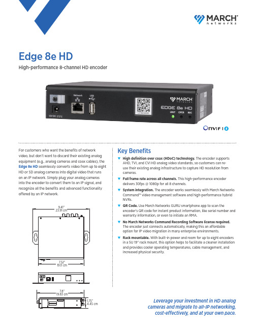
Edge 8e HDHigh-performance 8-channel HD encoderFor customers who want the benefits of network video, but don’t want to discard their existing analog equipment (e.g., analog cameras and coax cables), the Edge 8e HD seamlessly converts video from up to eight HD or SD analog cameras into digital video that runs on an IP network. Simply plug your analog cameras into the encoder to convert them to an IP signal, and recognize all the benefits and advanced functionality offered by an IP network.Key Benefits▼▼High definition over coax (HDoC) technology. The encoder supportsAHD, TVI, and CVI HD analog video standards, so customers can re-use their existing analog infrastructure to capture HD resolution from cameras.▼▼Full frame rate across all channels. This high-performance encoderdelivers 30fps @ 1080p for all 8 channels.▼▼System integration. The encoder works seamlessly with March NetworksCommand™ video management software and high-performance hybrid NVRs.▼▼QR Code. Use March Networks GURU smartphone app to scan theencoder’s QR code for instant product information, like serial number and warranty information, or even to initiate an RMA.▼▼No March Networks Command Recording Software license required.The encoder just connects automatically, making this an affordable option for IP video migration in many enterprise environments.▼▼Rack mountable. With built-in power and room for up to eight encodersin a 5U 19” rack mount, this option helps to facilitate a cleaner installation and provides cooler operating temperatures, cable management, and increased physical security.Leverage your investment in HD analog cameras and migrate to all-IP networking,cost-effectively, and at your own pace.North America . . . . . . . . . . . . . . . . . . . . .180****5564Latin America . . . . . . . . . . . . . . . . . . . . . +5255 5259 9511Europe . . . . . . . . . . . . . . . . . . . . . . . . . . . .+39 0362 17935Asia . . . . . . . . . . . . . . . . . . . . . . . . . . . . . . . .+65 6818 0963Australia and New Zealand . . . . . . . . .+61 1300 089 419Middle East and Africa . . . . . . . . . . . . . .+971 4 399 5525© 2018 March Networks . All rights reserved . Information in this document is subject to change without notice . MARCH NETWORKS, March Networks Command, March Networks Searchlight, March Networks RideSafe, and the MARCH NETWORKS logo are trademarks of March Networks Corporation . All other trademarks are the property of their respective owners . 060-3369-00-AEdge 8e HDencryptionSupported ProtocolsRTP, RTSP, HTTP, HTTPS, IPv4, TCP, UDP, DHCP, ARP, LDAP,ONVIF Profile APower Consumption10 Watts typicalConnectors (see rear panel diagram below)SD Analog/HD Analog Inputs Alarm/Audio/RS-485 (terminal block)Operating Conditions 32° to 122°F (0° to 50°C),8–90% Relative Humidity, non-condensingWeight 2.24lbs (1.02kg)Dimensions1.67 in H x 7.52 in W x 7 in D(42.4 mm H x 191 mm W x 178 mm D)Regulatory ApprovalsCE-EMC directive; 2004/108/EC; EMC Standards: EN55032; ICES-003; CISPR 32; AS/NZ CISPR 32;FCC Part 15 Subpart B EN61000-3-2:2014EN61000-3-3:2013EN 50130-4; EN55024Safety: IEC60950-1 (ed. 2); UL 60950-1 (ed. 2); CSA C22.2 No. 60950-1-07 (ed. 2)Environmental: ROHS2, WEEEIncluded Accessories Quick start guide and rubber feet for desktop mounting Optional Accessories19-inch rack mount with integrated single PSUEdge 8e HD rear panel。
ENCODER (P+F) 倍加福编码器介绍

旋转编码器—基础及注意事项P+F FA 2009.03内容一、编码器分类1.1 增量式编码器 1.2 绝对值编码器 1.3 防爆编码器二、编码器选型注意事项2.1 机械因素 2.2 环境因素 2.3 电气因素三、编码器使用注意事项3.1 安装注意事项 3.2 供电注意事项 3.3 软件设置 3.4 屏蔽的铺设2009.03P+F FAPage 2编码器简介• 什么是旋转编码器?– 把旋转机械参数转换为电气信号输出的数字式传感电子设备 ; – 用于旋转或直线等运动的监测,反馈角度、位置、速度和加速 度等机械参数。
ϕ, ω, n调制光调制电流频率脉冲2009.03P+F FAPage 3一、编码器分类旋转编码器增量型 绝对值单圈 轴套型 实心轴 半空轴 轴套型 实心轴多圈 半空轴防爆编码器:隔爆型、本安型、 防爆编码器:隔爆型、本安型、无火花型2009.03P+F FAPage 41.1 增量式编码器• 增量式编码器– 轴旋转一定角度,提供相应数量的脉冲;单位时间内的脉冲数可以用来 测量轴的转速; – 增量式编码器检测旋转中的相对位置变化时,需要一个参考起点,并进 行脉冲数的累加; 供电或电气受到扰动干扰时,脉冲计数将产生错误; 故障停车后,无法找回事故发生时的位置。
– 最大分辨率5000PPR,200kHz2009.03P+F FAPage 51.1 增量式编码器 – 信号输出• 反向通道– 用于抑制噪声干扰,改善了信号的传输可靠性,选型时优先选择6 通道 输出的编码器;干扰脉冲 信号 反向信号 耦合后的无干扰信号2009.03P+F FAPage 61.1 增量式编码器 – 信号输出• 推挽式输出 推挽式输出:组合了NPN和PNP输出方式– 提高了脉冲的上升沿宽度,改善了脉冲输出特性; – 具有较好的抗干扰能力,高速传输,距离更远; – 适用于中等开关频率范围的应用;• RS 422 线驱动:数据通过互补的两差分通道进行传输和接收 线驱动:– 用于干扰较严重的场合或长距离传输; – 用来替换TTL输出方式时,不使用反向通道;2009.03P+F FAPage 71.2 绝对值编码器• 绝对值编码器– 不产生脉冲,而是一串数据码,为每一个轴的位置提供一个 独一无二的编码数字值; ☺ 减轻了电子接收设备的计算任务; ☺ 当机器合上电源或电源故障后,有位置记忆功能; – 单圈分辨率最高16位(65536步) – 多圈分辨率最高14位(16384圈),总分辨率30位2009.03P+F FAPage 81.2 绝对值编码器 接口分类 绝对值编码器–接口分类: 接口分类: – SSI – AS-I – CANOPEN – DEVICENET – ETHERNET – 并行 – PROFIBUS-DP2009.03P+F FAPage 91.3 防爆编码器• 隔爆型 (Ex d)– 隔爆外壳可以承受爆炸性混合气体爆炸产生的压力,并且可以阻止 爆炸从壳体内传播到壳体外; – 设备可能含有易产生电弧、火花或易燃部件,但能保证爆炸仅限于 设备内部; – 1 区防爆,应用于正常运行时可能会出现气体、粉尘形式的爆炸性混 合物的场所。
BRG编码器使用手册说明书
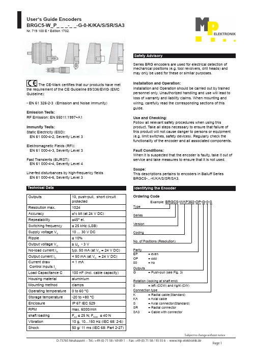
User‘s Guide EncodersBRGC5-W_P_ _ _-_ _-G-0-K/KA/S/SR/SA3Nr. 719 100 E • Edition 1702.The CE-Mark certifies that our products have met the requirement of the CE Guideline 89/336/EWG (EMC Guideline):- EN 61 326-2-3 (Emission and Noise Immunity)Emission Tests:RF Emission: EN 55011:1997+A1Immunity Tests:Static Electricity (ESD):EN 61 000-4-2, Severity Level 3Elektromagnetic Fields (RFI):EN 61 000-4-3, Severity Level 3Fast Transients (BURST):EN 61 000-4-4, Severity Level 4Line-fed disturbances by high-frequericy fields EN 61 000-4-6, Severity Level 3Series BRG encoders are used for electrical detection of mechanical positions (e.g. tool revolvers, drill heads) and may only be used for these or similar purposes.Installation and Operation:Installation and Operation should be carried out by trained personnel only. Unauthorized handling and use will Iead to loss of warranty and liability claims. When mounting and wiring, carefully read the corresponding sections of this guide.Use and Checking:Follow all relevant safety procedures when using this product. Take all steps necessary to ensure that failure of this product will not cause danger to persons or equipment (e.g. limit switches, safety devices). Regularly check the functionality of the encoder and all associated components.Fault Conditions:When lt is suspected that the encoder is faulty, take it out of service and take measures to ensure that lt is not used.Scope:This descriptions pertains to encoders in Balluff Series BRGC5-...-K/KA/S/SR/SA3. Safety AdvisoryTechnical DataOutputs 10, push-pull, short circuit protected Resolution max.1024Accuracy ±½ bit (at 24 V DC)Repeatability ±45° el.Switching frequency ≤ 25 kHz (LSB) Supply voltage V S 10 ... 30 V DC Ripple≤ 10% Output voltage V O ≥ U B - 3 VNo-load current I R typ. 50 mA (at V O = 24 V DC) Output current I O < 50 mA (at V O = 24 V DC)Current draw Control inputs I C < 1 mALoad Capacitance C 100 nF (incl. cable capacity)Housing material aluminium Mounting method clamps Operating temperature 0 to 60 °C Storage temperature -20 to +80 °C Enclosure IP 67 IEC 529RPM max. 6000/min shaft loading F AX ≤ 25 N; F RAD ≤ 40 N Vibration 10 g, 10...150 Hz (IEC 68: 2-6)Shock50 g/ 11 ms (IEC 68: Part 2-27)Identifying the EncoderOrdering CodeExample: BRGC5-WAP360-OP-G-0-SType Series Version CodingNo. of Positions (Resolution)Parity EP = even OP = odd 00= noOutputs G = Push-pull (see Fig. 3) Rotation (looking at shaft end)0 = left (CCW) and right (CW) Connection type K = Radial cable(Standard) KA = Axial cable S = Axial connector(Standard)SR = Radial connector SA3 = Cable with connectorUser‘s Guide EncodersBRGC5-W_P_ _ _-_ _-G-0-K/KA/S/SR/SA3Nr. 719 100 E • Edition 1702.Using the coupling:- Attach the encoder to the drive rigidly at one point only: either flange to flange or shaft to shaft. Use the couplings. - Be sure that the encoder shaft and the drive are an the same axis. Check the data sheet for the coupling to find the permissible axial or radial offset and the maximum angle error of the two shafts.- Be sure not to damage or bend the coupling excessively while installing and aligning it.- Tighten all mounting screws very carefully.Please note the following:- Never use force (e.g. hammer or blows) to install or align the encoder.- Do not exceed the bad tolerances given for the encoder shaft (see technical data).- Never step on the encoder, cord seal, or connector.BRG A3-...-K/KA-SA3Axial Offset Radial OffsetAngle ErrorBRG C5-...-KABRG C5-...-K BRG C5-...-S BRG C5-...-SRBRG C5-...-K-SA3Fig. 1: DimensionsNote the following:- Connect all cable according to the table at lower right.- Isolate all unused grounds (to avoid short circuit).- Make sure that self-wired connectors are sealed properly. Oil or water entering along the cable can enter the electronics area and destroy the unit.- The IP 67 rating can be assured only if your connections, especially in the case of short cables, meet the IP 67 specification also.- Do not route the BRG encoder cable parallel to AC lines, in order to avoid noise coupling.- Use shielded cable only, in order to avoid noise coupling.- Ground the shield on the control side only.- Plug or unplug the encoder connector only after power has been turned off.- Turn power on and off to the encoder and the input device at the same time only. Output Driver:At overload all outputs will be switched off. Switch off supply voltage and after the fault has been removed, turn power on.Fig. 3: Output circuittrack 1 to track 10+V0 VFig. 2: Cable/connector assembly for BRGC5-...-S/SRBRG C5-ST-...Connections BRGC5-...-K/KA/S/SR:Determine your BRG model and its resolution. The resolution is critical for the wiring.Pin Configuration: Solder side view of the connector Fig. 4: Connector for BRGC5-...-S/SRBKS-S55-00ca. 71Pin Configuration: Solder side view of the connectorFig. 5: Connector for BRGC5-...-SA3。
三菱变频器PLC选型价格表
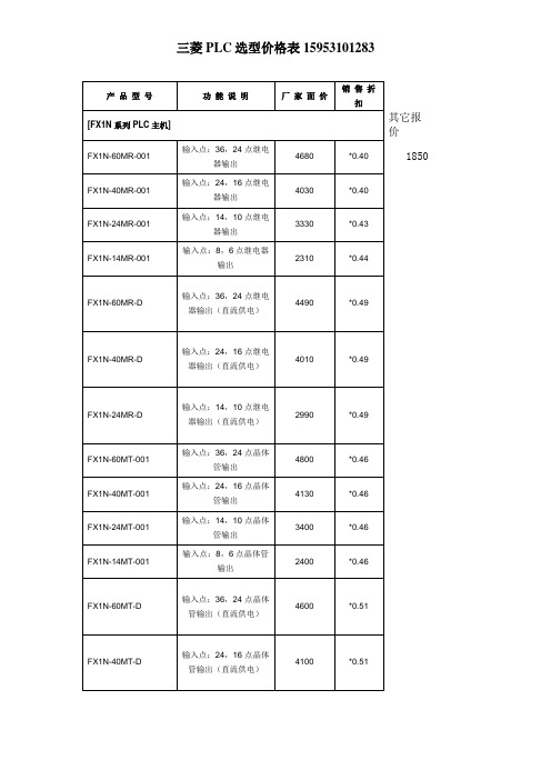
0.6
FX-EEPROM-8
8K EEPROM MEMORY CASSETTE
620
0.6
FX-EEPROM-16
16K EEPROM MEMORY CASSETTE
1020
0.6
[通讯模块]
FX2NC-232-ADP
RS232通讯模块
1230
*0.60
FX2NC-485-ADP
RS485通讯模块
输入点:16,16继电器输出(直流供电)
5180
*0.49
FX2N-128MT-001
输入点:64,64点晶体管输出
10330
*0.44
FX2N-80MT-001
输入点:40,40点晶体管输出
7180
*0.42
FX2N-64MT-001
输入点:32,32点晶体管输出
6410
*0.42
FX2N-48MT-001
输入点:36,24点晶体管输出
4800
*0.46
FX1N-40MT-001
输入点:24,16点晶体管输出
4130
*0.46
FX1N-24MT-001
输入点:14,10点晶体管输出
3400
*0.46
FX1N-14MT-001
输入点:8,6点晶体管输出
2400
*0.46
FX1N-60MT-D
输入点:36,24点晶体管输出(直流供电)
4通道D/A
3270
*0.46
FX2N-5A
4通道A/D, 1通道D/A
3400
*0.53
FX2N-8AD
8通道A/D
7630
*0.46
上海精浦绝对式编码器选型
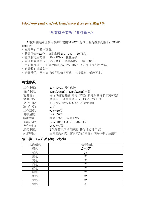
EAS124(24bit 超高分辨率,大孔径)
单圈24位超高分辨率、高精度、大孔径绝对值编码器EAS124
* 德国原装高精度刻线光学系统。
* 绝对值光电码盘,无需电池,抗干扰强 。
* 单圈 24 位超高分辨率,每圈 16777216 分割度。
* RS485 高速通迅。
允许转速: 输出刷新周期: 连接电缆: 外形特征: 信号调整:
2400 转/分 <1ms 1 米屏蔽电缆径向侧出(其余形式可订货) 金属外壳,密封双轴承结构(见外形尺寸附图 P16) 可 4mA 输出微调,20 mA 输出微调;可方向设置;可预设位 置,外部置位,例如外部置零
输出接口:(以产品说明书为准)
* 绝对值数字码盘,内置信号转换,4-20mA 模拟电流与 RS485 输出,方便连接各
种设备。
* EasyPro 软件设定,多用途、多功能,直接对应单圈角度、转动平移速度测量。
* 4mA 对应值、20mA 对应值任意设定及微调;方向设定;外部置位线设定预设
位置,安装方便,无需找零。
* 内部绝对值码盘,全数字化计值,信号无温度、机械影响,信号干扰零点飘移
测角度 测长度 测速度的多面手
* 内部绝对值码盘,全数字化计值。
* RS485 自由协议输出,或 Modbus RTU 输出。
* EasyPro 软件设定,多用途、多功能,直接对应单圈角度、转动平移速度测量。
* 多地址设定;通讯波特率设定,分辨率、方向设定。
* 外部置位线设定预设位置,安装方便,无需找零。
单圈 24 位超高分辨率、高精度绝对值编码器 EAS424
* 德国原装高精度刻线光学系统。
* 绝对值光电码盘,无需电池,抗干扰强 。
内策尔容栅编码器参数
内策尔容栅编码器参数全文共四篇示例,供读者参考第一篇示例:内策尔容栅编码器是一种常用的位置传感器,它可以将位置信息转换为数字信号,从而实现机械设备的精准定位和控制。
内策尔容栅编码器参数是指编码器的性能指标和技术参数,对于用户选型和使用具有重要意义。
下面我们将详细介绍内策尔容栅编码器的参数及其含义。
内策尔容栅编码器的分辨率是一个重要的参数。
分辨率是指编码器每旋转一周所能输出的脉冲数,通常以PPR(脉冲每圈)或CPR(脉冲计数数)为单位来表示。
分辨率越高,编码器的精度和分辨率就越高。
一般来说,内策尔容栅编码器的分辨率可以根据用户的需求进行选择,常见的分辨率有100、200、500、1000、2000等。
内策尔容栅编码器的工作电压是另一个重要参数。
工作电压是指编码器工作时所需要的电压范围,通常为DC5V、DC12V、DC24V等。
选择适合的工作电压可以确保编码器正常工作并提高其稳定性和可靠性。
内策尔容栅编码器的输出信号类型也是需要考虑的参数之一。
输出信号类型主要有两种,一种是模拟输出信号(如模拟电压和模拟电流),另一种是数字输出信号(如脉冲信号或数字串口信号)。
根据用户的需求和实际应用情况选择合适的输出信号类型可以更方便地与控制器或PLC进行连接。
内策尔容栅编码器的安装方式也是一个重要参数。
安装方式主要包括法兰式安装、轴端式安装、吸附式安装等。
不同的安装方式适用于不同的机械结构和空间限制,用户在选择编码器时需要结合实际情况进行合理选择。
内策尔容栅编码器的防护等级和环境温度也是需要注意的参数。
防护等级是指编码器对尘土、湿气、震动等外界环境的抵抗能力,通常使用IP等级来表示,如IP65、IP67等。
用户在选择时需要根据工作环境的特点来选择合适的防护等级。
编码器的工作环境温度也需要考虑,一般标准的工作温度范围为-10℃~+60℃,用户需要根据实际情况选择适合的编码器。
内策尔容栅编码器的参数是用户选择和应用时需要考虑的关键因素,合理的选择和配置可以提高机械设备的精度和稳定性,从而提高生产效率和品质。
博世 VideoJet X10 X20 X40 视频编码器 说明书

博世 VideoJet X 系列是工业级的高性能 CCTV 视频编码器,包含单路、双路或四路输入。
它们拥有精心设计的坚固外壳,可以应对各种极端的环境条件。
VideoJet X 编码器可以在非常苛刻的工作温度条件下工作:-30°C 至 +60°C(-22°F 至 +140°F)。
这些设备功能强大且配置灵活,提供了当今闭路电视领域中通过 IP 网络传输高性能视频的最尖端技术。
基本功能轻松应对苛刻的环境VideoJet X 编码器不仅是周边防护、边界和护栏控制等室外应用的理想选择,而且还是那些对环境要求极为严格的工业应用领域的首选佳品。
它拥有宽广的电流输入范围:10 至 30 VDC,当在偏远位置使用它们时,可以通过电池或太阳能供电,因此令您受益菲浅。
此外,它还拥有 SFP 插槽,使您无需使用外部光纤硬件即可直接连接光纤接口模块。
编码器具有工业级的抗震性能,因此非常适用于火车、公共汽车和其它交通工具等移动应用领域。
多种查看选项用户可以通过多种选项来查看 VideoJet X,其中包括运行 Web 浏览器的 PC 机、VIDOS、Bosch Video Management System 或将它集成到其它视频管理系统中。
通过将 IP 视频传输到高性能的 VIP XD 视频解码器或 VIDOS 监视器幕墙,可以获得超高清晰度的视频。
双码流技术VideoJet X 编码器采用双码流技术,可为每条通道生成两个独立的 IP 视频流。
这样,用户就能以两种不同的品质级别进行查看和录像,从而节省磁盘空间和带宽。
当发生报警时,它们可以发送附带 JPEG 图像的电子邮件。
优异的灵活性VideoJet X 编码器拥有无以伦比的录像灵活性。
用户可以通过网络传输视频,然后使用网络录像机 (NVR) 存储视频。
可以在内存、小型闪存上本地记录视频,也可采用可选的汽车级内置硬盘来记录视频。
此外,用户还可以采用通过网络连接的 RAID5 iSCSI 存储设备。
MicroE的光栅编码器
MicroE的光栅编码器MicroE Systems Inc.是一家总部设在麻萨诸塞州内蒂克市的美国公司,隶属于GSI集团公司精密运动部门。
其主要产品精密光栅编码器居世界领先地位。
更多技术内容及应用请联系北京艾玛特科技有限公司销售主管欧玉涛137******** MicroE的光栅编码器不仅具备高精度、高集成、全系列、低价格,它还拥有体积小、重量轻、高速度、安装快速、调整方便、可编程插补放大及强大的软件管理功能。
所有MicroE激光读数头均可应用于直线和圆形光栅。
MicroE光栅编码器主要有三个系列:(1)MercuryII系列,MicroE公司最新推出的同时适用于金属光栅和玻璃光栅的产品,分辨率可达1.2纳米,单只栅尺长度50米,高速运行;(2)MercuryI系列,主要特点是尺寸小,速度快,精度高,玻璃光栅,分辨率到5纳米,速度可以到7.2米/秒;(3)ChipEncoder 系列,读数头是芯片式,尺寸仅有7x11毫米,分辨率可以到1微米,价格低廉,适于小型设备大批量采购。
美国MicroE公司的光栅编码器具有微型、高速、智能的特点,是运动系统信号反馈的关键部件。
配备特有的智能软件,可以实现对编码器输出频率、分辨率的可编程控制,辅助编码器产品的安装调试,其分辨率范围从5μm到1.2nm,行程最长50米,能够实现用同一个读数头读取圆光栅、直线光栅、金属光栅和玻璃光栅,使用方便。
所有光栅都有零位信号输出,MII系列更具备粘贴式的左右限位,减小安装空间和节约成本。
MicroE公司编码器系列是光栅编码器产品微型化、智能化、高速化的典范。
独特的PuerPrecision光学系统、SmartPrecision电子细分系统和SmartPrecision软件,保证了MicroE编码器多功能和高性能的特性。
MicroE编码器产品现有MercuryII系列、Mercury系列、ChipEncoder系列和DRC系列。
信捷编码器伺服插头50针引脚定义

信捷编码器伺服插头50针引脚定义当我们谈论编码器时,信捷编码器无疑是一个值得关注的品牌。
而在信捷编码器中,50针插头引脚定义更是一个需要深入了解的主题。
今天,我将带大家深入探讨信捷编码器伺服插头50针引脚定义,希望通过本文的阐述,能够让大家对这一主题有更加全面、深刻的理解。
1. 引言信捷编码器在伺服系统中起着至关重要的作用,而50针插头引脚定义则是编码器功能实现的关键。
在这篇文章中,我们将从简单到复杂,由浅入深地探讨信捷编码器伺服插头50针引脚定义,以便读者能够更深入地理解这一主题。
2. 信捷编码器伺服插头50针引脚定义的基本概念在了解信捷编码器伺服插头50针引脚定义之前,我们首先需要了解编码器的基本功能和结构。
编码器作为一种测量旋转运动的装置,通常由光栅器和信号处理器两部分组成。
在信捷编码器中,50针插头引脚定义则是用来连接编码器与伺服系统之间的重要接口,包括信号输入、输出、电源和地线等。
3. 50针插头引脚定义的具体功能信捷编码器伺服插头50针引脚定义中,不同的引脚代表着不同的功能。
这些功能包括但不限于正交信号输入、编码器供电、报警信号输出等。
在开发和应用中,了解每个引脚的定义和功能对于正确连接和使用编码器至关重要。
4. 我对信捷编码器伺服插头50针引脚定义的个人观点和理解在我看来,深入理解信捷编码器伺服插头50针引脚定义,可以帮助我们更好地应用编码器,提高伺服系统的性能和稳定性。
了解50针插头引脚的定义和功能,可以让工程师更加方便地进行系统的设计和调试工作。
通过不断地学习和实践,可以更好地理解并掌握编码器在伺服系统中的应用。
5. 总结与回顾通过本文的阐述,我们深入探讨了信捷编码器伺服插头50针引脚定义这一主题。
从基本概念到具体功能,我们逐步展开了对这一主题的全面评估。
希望通过本文的阐述,读者能够对信捷编码器伺服插头50针引脚定义有更加全面、深刻的理解,并在实际应用中取得更好的效果。
在这篇文章中,我们着重探讨了信捷编码器伺服插头50针引脚定义的重要性和功能。
RST2使用手册

锐普德数控
RST系列交流伺服驱动器用户手册
本产品的设计和制造并非是为了使用在对人身安全有威胁的机械和系统中。 用户的机械和系统选用本产品时,须在设计和制造中考虑安全防护措施,防 止因操作不当或本产品异常而引发意外事故。 伺服驱动器即使断电后,高压仍会保持一段时间,断电后 5 分钟内请勿拆卸 电线,不得触摸端子排。 参与拆卸与维修的人员必须具备相应的专业知识和工作能力。 本驱动器电源推荐使用三相隔离变压器单独供电。 切勿直接把交流 380V 接于 U、V、W 端子,否则将会导致驱动器永久损坏。 损坏或有故障的产品不可投入使用。 必须按产品储运环境条件储存和运输。 搬运伺服电机时,不得拖拽电线、电机轴和编码器插座。 伺服驱动器及伺服电机不得承受外力及撞击。 受损或零件不全时,不得进行安装。 必须安装在有足够防护等级的控制柜内。 必须与其它设备间保留足够的间隙。 必须有良好的散热条件。 防止尘埃、腐蚀性气体、导电物体、液体及易燃易爆物质侵入。 安装务必牢固,防止因振动松脱。 防止液体侵入损坏电机和编码器。 禁止敲击电机和电机轴,以免损坏编码器。 电机轴不可承受超载极限的负荷。 伺服驱动器和伺服电机必须良好接地。 接线必须正确而且牢固,否则可能会使伺服电机错误运转,也可能因接触不 良损坏设备。
锐普德在此重申: 以上安全防范说明所涉及的各项请务必重视并遵守
iii
锐普德数控
RST系列交流伺服驱动器用户手册
iv
目录
目录
前言 ......................................................................................................................i 第1章 产品检查与安装........................................................................................1 1.1 产品检查 ...................................................................................................1 1.2 产品铭牌 ...................................................................................................1 1.3 型号定义 ...................................................................................................2 1.4 产品前面板 ................................................................................................3 1.5 伺服电机安装 ............................................................................................4 1.5.1 安装环境条件 .....................................................................................4 1.5.2 安装注意事项 .....................................................................................4 1.6 电机旋转方向定义.....................................................................................4 第2章 接线 ..........................................................................................................5 2.1 配线规格 ...................................................................................................5 2.2 配线方法 ...................................................................................................5 2.3 注意事项 ...................................................................................................5 2.4 标准连接 ...................................................................................................7 2.4.1 位置控制.............................................................................................7 2.4.2 简易位置控制图 .................................................................................8 第3章 接.......................................................................9 3.1 接线外观图 ................................................................................................9 3.2 驱动器电源端子 ......................................................................................10 3.3 控制信号端子CN1a,CN1b..................................................................12 3.4 编码器反馈信号端子CN2a,CN2b ......................................................17 3.5 接口类型 .................................................................................................18 3.5.1 开关量输入接口 Type1 ...................................................................18
80X01和80X02电气采样模块扩展器说明书
80X01and80X02Electrical Sampling Module Extender InstructionsWarrantyWarranty Tektronix warrants that the parts and modules(“parts”)that it manufactures andsells will be free from defects in materials and workmanship for a period of three(3)months from the date of shipment.If any such part proves defective duringthis warranty period,Tektronix,at its option,either will repair the defective partwithout charge,or will provide a replacement in exchange for the defectivepart.Parts and modules used by Tektronix for warranty work may be new orreconditioned to like new performance.All replaced parts and modules becomethe property of Tektronix.In order to obtain service under this warranty,Customer must notify Tektronixof the defect before the expiration of the warranty period and make suitablearrangements for the performance of service.Customer shall be responsible forpackaging and shipping the defective part to the service center designated byTektronix,with shipping charges prepaid.Tektronix shall pay for the return ofthe part to Customer if the shipment is to a location within the country in whichthe Tektronix service center is located.Customer shall be responsible for payingall shipping charges,duties,taxes,and any other charges for parts returned toany other locations.This warranty shall not apply to any defect,failure or damage caused by improperuse or improper or inadequate maintenance and care.Tektronix shall not beobligated to furnish service under this warranty a)to repair damage resulting fromattempts by personnel other than Tektronix representatives to install,repair orservice the part;b)to repair damage resulting from improper use or connection toincompatible equipment;c)to repair any damage or malfunction caused by theuse of non-Tektronix supplies;or d)to service a part that has been modified orintegrated with other products or parts when the effect of such modification orintegration increases the time or difficulty of servicing the part.THIS WARRANTY IS GIVEN BY TEKTRONIX WITH RESPECTTO THE PART IN LIEU OF ANY OTHER WARRANTIES,EXPRESSOR IMPLIED.TEKTRONIX AND ITS VENDORS DISCLAIM ANYIMPLIED WARRANTIES OF MERCHANTABILITY OR FITNESS FOR APARTICULAR PURPOSE.TEKTRONIX'RESPONSIBILITY TO REPAIR ORREPLACE DEFECTIVE PARTS IS THE SOLE AND EXCLUSIVE REMEDYPROVIDED TO THE CUSTOMER FOR BREACH OF THIS WARRANTY.TEKTRONIX AND ITS VENDORS WILL NOT BE LIABLE FOR ANYINDIRECT,SPECIAL,INCIDENTAL,OR CONSEQUENTIAL DAMAGESIRRESPECTIVE OF WHETHER TEKTRONIX OR THE VENDOR HASADV ANCE NOTICE OF THE POSSIBILITY OF SUCH DAMAGES.Copyright©Tektronix*P071320600*Important safety informationImportant safety informationThis manual contains information and warnings that must be followed by the userfor safe operation and to keep the product in a safe condition.To safely perform service on this product,additional information is provided atthe end of this section.(See page2,Service safety summary.)General safety summaryUse the product only as specified.Review the following safety precautions toavoid injury and prevent damage to this product or any products connected to it.Carefully read all instructions.Retain these instructions for future reference.To avoidfire or personalinjury Do not operate without covers.Do not operate this product with covers or panels removed,or with the case open.Hazardous voltage exposure is possible.Do not operate with suspected failures.If you suspect that there is damage to this product,have it inspected by qualified service personnel.Disable the product if it is damaged.Do not use the product if it is damagedor operates incorrectly.If in doubt about safety of the product,turn it off and disconnect the power cord.Clearly mark the product to prevent its further operation.Examine the exterior of the product before you use it.Look for cracks or missing pieces.Do not operate in wet/damp conditions.Be aware that condensation may occur if a unit is moved from a cold to a warm environment.Do not operate in an explosive atmosphere.Keep product surfaces clean and dry.Remove the input signals before you clean the product.Service safety summaryThe Service safety summary section contains additional information required tosafely perform service on the product.Only qualified personnel should performservice procedures.Read this Service safety summary and the General safetysummary before performing any service procedures.Do not service alone.Do not perform internal service or adjustments of thisproduct unless another person capable of renderingfirst aid and resuscitation ispresent.Important safety informationDisconnect power.To avoid electric shock,switch off the product power anddisconnect the power cord from the mains power before removing any covers orpanels,or opening the case for servicing.Terms in this manualThese terms may appear in this manual:WARNING.Warning statements identify conditions or practices that could resultin injury or loss of life.CAUTION.Caution statements identify conditions or practices that could result indamage to this product or other property.Symbols and terms on the productThese terms may appear on the product:DANGER indicates an injury hazard immediately accessible as you readthe marking.WARNING indicates an injury hazard not immediately accessible as youread the marking.CAUTION indicates a hazard to property including the product.When this symbol is marked on the product,be sure to consult the manualtofind out the nature of the potential hazards and any actions which have tobe taken to avoid them.(This symbol may also be used to refer the user toratings in the manual.)The following symbol(s)may appear on the product:Product descriptionEnvironmental considerationsThis section provides information about the environmental impact of the product.Product end-of-lifehandling Observe the following guidelines when recycling an instrument or component: Equipment recycling.Production of this equipment required the extraction and use of natural resources.The equipment may contain substances that could be harmful to the environment or human health if improperly handled at the product’s end of life.To avoid release of such substances into the environment and to reduce the use of natural resources,we encourage you to recycle this product in an appropriate system that will ensure that most of the materials are reused or recycled appropriately.This symbol indicates that this product complies with the applicable EuropeanUnion requirements according to Directives2002/96/EC and2006/66/ECon waste electrical and electronic equipment(WEEE)and batteries.Forinformation about recycling options,check the Support/Service section of theTektronix Web site().Restriction of hazardoussubstances This product is classified as an industrial monitoring and control instrument accessory,and is not required to comply with the substance restrictions of the recast RoHS Directive2011/65/EU until July22,2017.Product descriptionThe80X01(one-meter)and80X02(two-meter)electrical sampling moduleextender cables(referred to as the extender cable or the extender in this document)are for use with supported electrical sampling modules.(See page5,Supportedmodules.).Use the extender to move the sampling module from its instrument compartment,closer to the device under test,so that you can use shorter signal ing theextender avoids input-signal degradation that can occur when using long-lengthsignal cables between the sampling module and the device under test.Product descriptionSupported sampling oscilloscopesThe extender cable is for use with the following sampling oscilloscopeinstruments:DSA8300Digital Serial AnalyzerLegacy sampling oscilloscope instruments:DSA8200Digital Serial AnalyzerCSA8000,CSA8000B,and CSA8200Communications Signal AnalyzersTDS8000,TDS8000B,and TDS8200Digital Sampling OscilloscopesSupported modules80E01,80E02,80E03,80E04,80E06,80E11,and80E11X1Electrical samplingmodulesOther modules82A04BGuidelinesObserve the following guidelines to avoid damaging your sampling modules orinstruments:The extender cannot be used with any large-compartment modules.Some small modules are mechanically blocked from use with the extender.When connecting an80X02extender to an80X01extender,connect theextenders in the following order:Instrument-80X02-80X01-samplingmodule.Always wear a grounded wrist strap,grounded foot strap,and static resistantapparel while installing module extenders and modules.Observe standard anti-static handling precautions when connecting signalcables to sampling modules.Change to instrument operating temperature range when using80X01or80X02When you install one or more of the extenders in an instrument,the upper end ofthe instrument operating temperature range changes as follows:No extender cable(s)installed:+10°C to+40°CWith extender cable(s)installed:+10°C–+35°CInstallation instructionsChange to minimum horizontal position when using80X01or80X02Installing the80X01or80X01extender cable increases the minimum horizontalposition setting as follows:80X01:+5ns80X02:+10nsThis affects waveforms acquired from all modules,extended or not.Horizontalposition is a global setting.Installation instructionsCAUTION.For the DSA8300with TekScope software version6.1.X or greater,follow proper module exchange procedures to remove,install,or exchangemodules or module extenders with the instrument powered on(View/ChangeModule Config tool).Refer to the product documentation for instructions.For all legacy instruments(DSA8200Digital Serial Analyzer,CSA8000,CSA8000B,and CSA8200Communications Signal Analyzer,TDS8000,TDS8000B,and TDS8200Digital Sampling Oscilloscopes),andDSA8300instruments with TekScope software version6.0.X,power off theinstrument before removing,installing,or exchanging modules or moduleextenders.Removing or installing modules in these instruments while powered onmay result in damage to the module and/or mainframe instrument.Always wear a grounded wrist strap,grounded foot strap,and static resistantapparel while installing this module extender and any modules.Observe standard anti-static handling precautions when connecting signal cablesto sampling modules.NOTE.DSA8300Digital Serial Analyzer instruments with TekScope softwareversion6.1.X or greater have a View/Change Module Config function that allowsremoving,installing,or exchanging modules or module extenders while the maininstrument is powered on.All earlier instruments,and earlier TekScope softwareversions,require that you power off the main instrument before removing,installing,or exchanging modules or extenders.NOTE.The80X02sampling module extender is keyed to prevent connecting todevices not intended to be extended and to prevent two or more80X02extendersfrom being connected in series.To connect an80X02extender to an80X01extender,connect the cables in thefollowing order:Instrument-80X02-80X01-sampling module.Installation instructions Do the following steps to install the extender between the instrument and the electrical sampling module:1.Connect an antistatic wrist strap to the instrument front-panel groundconnection.Place the strap on your wrist.2.Remove power:DSA8300(with TekScope software version6.1or later):Run theUtilities>View/Change Module Config tool;follow on-screeninstructions to remove a module and/or install the“To Instrument”end ofthe extender in a small module slot.Then go to step4.DSA8300with TekScope software version6.0X,and all Legacyinstruments:Push the On/Standby button on the front panel to poweroff the instrument.If there is a module in the slot where you are installing the extender,remove the module after the instrument has powered off. 3.Install the extender connector labeled To Instrument into a suitable slot inthe instrument.See the sampling module user manual if you require more information.4.Attach the connector marked To Sampling Module to a supported samplingmodule.(See page5.)5.Apply power to the module:DSA8300(with TekScope software version6.1or later):Click theFinish button in the View/Change Module Config tool.This appliespower to the module slot.DSA8300with TekScope software version6.0X,and all Legacyinstruments:Push the On/Standby button on the front panel to poweron the instrument.Wait for the boot-up cycle to complete.Installation instructions6.Run a compensation on each channel of all newly installed modules or moduleextenders(select Utilities>Compensation).You must run compensation,even if module(s)and/or extenders were moved from one slot to another.Seethe instrument documentation or TekScope application help for instructionson how to run compensation.7.You can now use the instrument to take measurements.NOTE.Check the module compensation status for thefirst20minutes byviewing the compensation status icon on the instrument user interface,or byquerying the compensation status from the programmatic interface.It may takeup to20minutes for the sampling module on the extender cable to reach astable temperature.If the compensation status indicates that a module requirescompensation,rerun compensation on the module to be sure that the instrumentand module are within measurement accuracy specifications.。
红树伟业512线编码器使用手册
红树伟业512线编码器使用手册感
谢您使用红树伟业“512线3相增量式旋转
测速编码器”。
本手册内容是红树伟业研发测试学习过程中产品参数:
接口说明:
产品分为三种线的:PH2.0短线(7cm)线长PH2.0长线(24cm线长)
FC长线(24cm线长)
对应的接口信息分别为:
PH线的:
FC线的:
PS:四轮车模在运行的过程中轮胎是不会出现的反转的情况,所以我们的四轮车模只需要使用A相输出即可用来做速度闭环控制的反馈信号,即使用Pin1、Pin2、Pin3便可完成车模速度控制。
三轮车和直立车在运行过程中会出现轮胎反转的情况,所以我们的三轮车和直立车只要A相输出和方向输出,即使用Pin1、Pin2、Pin3、Pin4才可完成车模速度控制。
安装方法:
C车模配合我们的编码器支架和编码器齿轮:
装车效果图:
脉冲输出波形测试:测试连接:
Pin1----GND
Pin2----VCC(3.3V或5V建议用3.3v)
Pin3----为测速脉冲输出信号,用单片机捕获
Pin4----为方向信号,输出为高低电平量
Pin5----为旋转一周产生的一个脉冲量,用来计量圈数或者测量角度,由于比较少用,所以只在FC线接口上有该引脚,PH2.0接口上没有保留该引脚。
Ps:示波器与电源需要共地如图所示:
FC线:
PH2.0接口线:
操作方法:连接好后,用手波动编码器齿轮观察示波器窗口如图所示:
示波器波形如图所示:。
GST-BMQ-4编码器安装使用说明书

GST-BMQ-4编码器安装使用说明书(Ver.1.01,2022.06)一、概述GST-BMQ-4编码器(以下简称编码器)可对电子编码的探测器或模块进行地址码、灵敏度、设备类型等的读出和地址码、灵敏度的写入功能以及单点测试功能,还可对总线上的探测器或模块进行在线设备统计、批量测试、重码检测等操作。
二、特点1.该编码器采用手握式结构,外形小巧,携带方便,操作简单;2.可对公司生产的总线型探测器、模块等设备编码,也可进行在线设备统计、批量测试、重码检测等操作;3.采用128*128点阵液晶显示,支持汉字、数字、字母、图标显示,显示直观;4.具有低功耗模式、自动关机功能;5.具有电池欠压指示功能;6.具备背光显示功能。
三、技术特性1.电源:4节5号1.5V电池或DC5V USB电源2.工作电流≤12mA3.待机电流≤0.3mA4.使用环境:温度:-10℃~+50℃相对湿度≤95%,不凝露5.尺寸:166mm×62mm×26mm6.外壳防护等级:IP40四、结构特征外形示意图如图1所示。
图1外形示意图1.总线接口2.TYPE-C接口3.开关键4.液晶屏5.背光键6.金属触片7.滑动按钮8.铭牌9.电池盒后盖10.固定螺钉其中各部分名称和功能说明如下:1.总线接口:编码器通过总线接口与探测器或模块相连。
2.TYPE-C接口:用于外置供电或编码器固件版本升级(固件升级属于专业操作,本说明书不做介绍)。
3.开机键:完成系统硬件开机和关机操作。
4.液晶屏:显示有关探测器的一切信息和操作人员输入的相关信息,并且当电源欠压时给出指示。
5.背光键:液晶屏背光的打开与关闭。
6.金属触片:编码器通过金属触片与探测器相接触(目前只适用G5系列探测器)。
7.滑动按钮:通过滑动按钮推出或收回金属触片。
8.铭牌:印于编码器背面。
9.电池盒后盖:内部放置电池。
10.固定螺钉:将电池盒后盖和后壳固定在一起。
五、使用及操作1.电池的初次安装打开电池盖螺丝和电池盒后盖,将电池正确装在电池盒内,盖好后盖,拧紧螺丝。
普洛图安全PLC手册绝对编码器说明书

PLUTO Safety-PLCManualAbsolute EncodersTable of contents:1General (3)1.1Reaction time (3)1.2Safety parameters (3)2Electrical (4)2.1Separation with Gateway in Bridge Mode (5)2.2CAN bus data (5)3Singleturn encoder RSA 597/RHA 597 (6)3.1Address setting (6)3.2Software settings (7)3.2.1Baudrate (7)3.2.2Scale (7)3.2.3Position adjustment (8)3.3Speed limit (9)3.4Technical data (9)3.4.1Electrical data (9)3.4.2Mechanical data (10)4Multiturn encoder RSA 698/RHA 698 (13)4.1Connectors (13)4.2Indicators (13)4.3Address setting (14)4.4Baudrate (14)4.5Software settings (14)4.5.1Scaling (15)4.5.2Position adjustment (15)4.6Technical data (16)4.6.1Electrical data (16)4.6.2Mechanical data (17)5PLC Software - Description of function blocks (20)5.1SafeEncoder (20)5.2SafeEncoderMult (21)5.2.1SafeEncoderMult32 (22)5.3EncoderCam (23)5.3.1EncoderCam_R (23)5.3.2EncoderCam32 (23)1 GeneralPluto can handle up to 16 absolute encoders connected to the CAN bus. However, the encoders themselves can only be addressed to one of 8 different addresses (for Multiturn encoders 9 addresses, but a safe solution requires that the encoders are mounted in pairs). This leads to that in practice a maximum of 8 encoders can be used.One of the Pluto units on the bus must have software option for communication with the encoders. This special Pluto sends cyclically a sync telegram, which trigs all encoders on the bus to read the position and send a telegram with the position value back to the bus. The special Pluto can read the encoder telegrams and evaluate them. With block functions in the PLC code it is then possible to make a dual channel function with two encoders. Out of this the user gets failsafe values for position and speed including stand still monitoring and over speed detection.The encoders are standard absolute encoders with modified software to meet the safety requirements.1.1 Reaction timeThe encoders are read every 10 ms. The system tolerates that a single reading of an encoder fails, but if two or more fails, it leads to failure alarm. This leads to the response times as below. Response time:Normal conditions: 11 ms + program execution time ≈ 14 msBy fault: 31 ms + program execution time ≈ 34 ms1.2 Safety parametersA system with two encoders connected to a Pluto with a PLC program which uses the block functions described in this manual (see 5) meets the safety levels below.The values are the same as for the use of other input types, such as normal digital I/O:s or AS-i bus sensors. The values are including the encoders.SIL according to IEC 61508, EN 62061SIL 3Charge pump outputs* (Q2, Q3)PFD AV (for proof test interval = 20 years) 1.5 x 10⁻⁴PFH D according to IEC 61508, EN 62061 1.5 x 10⁻⁹Relay outputs* (Q0, Q1, Q4, Q5)PFD AV (for proof test interval = 20 years) 1.5 x 10⁻⁴PFH D according to IEC 61508, EN 62061 2.0 x 10⁻⁹PL according to EN ISO 13849-1PL eCategory according to EN ISO 13849-14MTTF d according to EN ISO 13849-1High/1500 yearsDC avg according to EN ISO 13849-1High*Encoder to output.For more details see Pluto hardware manual.2Electrical2.1 Separation with Gateway in Bridge ModeBy using a Gateway GATE-C2 or GATE-D2 in bridge mode it is possible to separate the Encoders so that different Pluto units communicate with different Encoders. The Gateway will filter out the Encoder telegrams, but let the other telegrams pass through. (See 8.1 “Pluto filter” in thePluto_Gateway_Manual.)2.2 CAN bus dataEach encoder gives bus load equivalent to two Pluto units. This leads to that with a certain CAN speed, the maximum amount of Pluto units will be reduced by two for each encoder. For example a Pluto-bus running with 250 kbit/s and 4 encoders can have 14-24 Pluto units instead of 22-32.For bus data as cable length / baudrate, amount of bus nodes, etc., see Pluto - Operating instructions - Hardware.In this example Pluto 1 communicates with Encoder 1 and 2, while Pluto 3 communicates with Encoder 3 and 4.3 Singleturn encoder RSA 597/RHA 597The singleturn encoder comes in four variants:·RSA 597 with 12-pin connector.·RSA 597 with 1.5 meter cable.·RHA 597 with hollow shaft and 2 meter cable.·RHA 597 with hollow shaft and 10 meter cable.Besides connection of power supply and CAN bus the connector/cable is also used for setting the address with jumpers (see Address settings below).3.1 Address settingThe encoder must be addressed 1-8 by connecting pin 1…4 with pin 11 in the connector/cable. By exchange of encoder the addressing will automatically be made by fitting the connector.1 = Not connected0 = Connected to pin 11.Example: Encoder address 3 – Pin 3 connected to Pin 11 and Pin 1, 2, 4 not connected.3.2 Software settingsAn encoder can be adjusted from Pluto by using Terminal Window in Pluto Manager.By connection the prompt Pluto_A> shall be visible.Type “encoder” for entering the encoder menu where it is possible to change baudrate (B), set the current position (A) and rescale the encoder (I).NOTE: If an encoder with wrong baud rate is connected to a running Pluto buss the CAN-bus communication fails.3.2.1 BaudrateBaudrate: 125, 250, 500, 800 kbit/s or 1 Mbit/s. (Default Pluto setting 400kbit/s is not possible.)At delivery the encoders are set to 500 kbps. Note that the encoder must be powered off/on before the new setting is valid.3.2.2 ScaleExample of setting the scale to degrees.Addr.Pin 4Parity Pin 3Bit 2Pin 2Bit 1Pin 1Bit 010001200103101140100511016111070111810003.2.3 Position adjustment The current position is setto 90.3.3 Speed limitBy use of single turn encoder for speed monitoring the maximum allowed rotating speed is limited to 50 rev/s = 3000 rpm. If the speed is exceeded the speed value will be negative.Note: It must be secured by limitations in application that the maximum speed is not exceeded or that no dangerous situations can occur if it does.Examples of such limitations are: An induction motor which speed is limited by the frequency or a hydraulic cylinder which is limited by a maximum pump capacity.3.4 Technical dataType designation Variant Interface Article number, ABBRSA 597With 12-pole connector CAN042TLA020070R3600RSA 597With 1.5 m. cable CAN042TLA020070R3300RHA 597Hollow shaft, with 2 m. cable CAN042TLA020070R3400RHA 597Hollow shaft, with 10 m. cable CAN042TLA020070R5900Encoder dataType RSA 597, RHA 597Operating temperature-40°C .. +70°CStorage temperature-30°C .. +70°CIngress protection class IP-67 according to IEC 60529At shaft inlet IP-66 according to IEC 60529Vibration (55 to 2000Hz)< 300 m/s2 according to IEC 60068-2-6Shock (6ms)< 2000 m/s2 according to IEC 60068-2-27Cover material AluminiumCover surface treatment Coated and cromated or anodizedWeight Approx. 300gAccuracy and resolutionResolution13 Bit, 8192 positions per revolutionAccuracy± ½ LSB3.4.1 Electrical dataDefault baud rate is 500kbit/s.Power supply9-36 VdcPolarity protected YesOutput interface CANPlutoShort circuit protected YesInterface CAN specifications 2.0 part A and BApplication layer Safe EncoderBaud rate 5 kbit/s - 1 Mbit/sCAN identifier 3 bit hardware adjustableAddress input Active lowCode type BinaryProgrammable functions Resolution, PresetDirection, Baud rateNode IDCurrent consumption50mA @ 24VdcMax current consumption 100mA3.4.2 Mechanical dataRSA 597 with 12-pin connectorShaft specification Flange specificationShaft typeØ 10 with face Flange type63, Synchro Axial shaft load50 N Outer diameterø58 mm Radial shaft load60 N Mounting holes 3 x M4 Mech. permissible speed 6000 rpm (12 000)Flange material Aluminium Shaft material Stainless steel Surface treatment Anodized Moment of inertia2,0 x 10-6 kgm2RSA 597 with cableShaft specification Flange specificationShaft typeØ6with face Flange type63, Synchro Axial shaft load50 N Outer diameterø58 mm Radial shaft load60 N Mounting holes 3 x M4 Mech. permissible speed 6000 rpm (12 000)Flange material Aluminium Shaft material Stainless steel Surface treatment Anodized Moment of inertia1,9 x 10-6 kgm2RHA 597 hollow shaft with cableShaft specification Flange specificationHollow shaft typeØ 12hs Flange type56, hollow shaft Axial shaft load10 N Diameterø58 mmRadial shaft load20 N Flange material Aluminium Mech. permissible speed 6000 rpm Surface treatment AnodizedShaft material Stainless steel Torque support Torque arm Moment of inertia2,0 x 10-6 kgm24 Multiturn encoder RSA 698/RHA 6984.1 Connectors4.2 IndicatorsSTATUS : Follows the CANopen standard.GreenOK Flashing red/greenFault Example:Wrong baudrate Baudrate conflict Flashing green/short redNo contact with busMODULE: Indicates sensor status.GreenOK Flashing redFault Example:Address switches set to different values Baudrate switch set to 9.Sensor faultCAN Bus Pin CAN Shield 1(CAN V+)*2(CAN GND)*3CAN High 4CAN Low5*Normally not usedPower supply 24 VDC Pin +24 Volt 1-20 Volt 3-4Switches under the cover.Address switches must be set to same value.Connectors and indicators4.3 Address settingThe address is set by the two rotaryswitches under the cover. The two address switches shall be set to the same value.Note : The encoder must be powered off/on before the new setting is valid.4.4 BaudrateThe baudrate is set by the switch under the cover.Note : The encoder must be powered off/on before the new setting is valid.4.5 Software settingsVia Terminal window in Pluto Manager it is possible to scale, set actual position and get information.- Connect the computer to Pluto and start Pluto Manager. Start the terminal window.- Start by typing encoder and v and sto see if the encoders are present on the bus:In this case encoder 5 and 6 are present on the bus.The “v” command (version) shows serial number, version of hardware and software and operating time.The status command “s” gives scaled and hardware resolution, position. Here the encoders are configured to emulate singleturn encoders (scaled res turns=1) with 4000 increments/rev.The encoders must be scaled so that the total range is with 0 to 31999.AddressSwitch 1, 211, 122, 233, 344, 455, 566, 677, 788, 899, 9Baud rate Baudrate switch10 Kbit 020 Kbit 150 Kbit 2125 Kbit 3250 Kbit 4500 Kbit 5800 Kbit 61000 Kbit 7400 Kbit 8Error94.5.1 ScalingThe encoder is rescaled by the command “i”.In below example the encoder is set to 100 increments/rev in multiturn mode. This means we can have up to 320 turns within the total range. Rotation direction is clockwise:By typing “s” after the rescaling we can see that the total range is 409600, but since Pluto only has 16-bit arithmetic only the part between 0 and 31999 is usable.4.5.2 Position adjustmentIn below example the actual encoder position is adjusted to 5000.By typing “s” after the rescaling we can see that the position is changed to 5000.If the encoder is turned and “s” is typed again we can see that the position is changed.It is also possible to type “p” (position) to get the actual position. If position is displayed by the status command but not for the “p” command, probably the position is outside range 0-31999.Type designation Variant Interface Article number, ABB RSA 698Multiturn CAN042TLA020070R3700 RSA 698Multiturn, 6mm shaft CAN042TLA020071R7800 RHA 698Multiturn, Hollow shaft CAN042TLA020071R7900 Encoder dataType RSA 698, RHA 698Operating temperature-40°C .. +70°CStorage temperature-30°C .. +70°CIngress protection class IP-67 according to IEC 60529At shaft inlet IP-66 according to IEC 60529Vibration (55 to 2000Hz)< 100 m/s2 according to IEC 60068-2-6Shock (6ms)< 2000 m/s2 according to IEC 60068-2-27Cover material AluminiumCover surface treatment AnodizedWeight Approx. 400gAccuracy and resolutionTotal Resolution25 BitSingle turn resolution13 Bit, 8192 positions per revolutionMultiturn resolution12 Bit, 4096 absolute number of revolutionsAccuracy± ½ LSB4.6.1 Electrical dataPower supply9-36 VdcPolarity protected YesOutput interface CANPlutoNode address Settable via DIP SwitchBaud rate Settable via switch, Max 1MBit/sDefault Baud rate125 kBit/sCode type BinaryProgrammable functions Scaling, PresetCode sequenceCurrent consumption90 mA @ 24VdcMax current consumption150 mA @ 24VdcRSA 698 MultiturnShaft specification Flange specificationShaft typeØ 10round Flange type63, Synchro Axial shaft load50 N Outer diameterø58 mm Radial shaft load60 N Mounting holes 3 x M4 Mech. permissible speed 12000 rpm Flange material Aluminium Shaft material Stainless steelMoment of inertia2,0 x 10-6 kgm2Shaft specificationFlange specificationShaft type Ø6round Flange type 63, Synchro Axial shaft load 50 N Outer diameter ø58 mm Radial shaft load 60 N Mounting holes 3 x M4Mech. permissible speed 12000 rpm Flange materialAluminiumShaft material Stainless steelMoment of inertia1,9 x 10-6 kgm2Shaft specification Flange specificationShaft typeØ 12hs Flange type58,HSAxial shaft load10 N Outer diameterø58 mm Radial shaft load20 N Torque support Stator coupling Mech. permissible speed 6000 rpm Flange material Aluminium Shaft material Stainless steelMoment of inertia4,3 x 10-6 kgm25 PLC Software - Description of function blocksThe safety blocks for reading encoders are located in file “encoder01.fps”.5.1 SafeEncoderFunction block for singleturn encoders generating safe position and speed value out of two absolute encoders.------------ Function ------------------------------The function block reads and evaluates two absolute encoders. Theaverage of the two encoders is calculated and set to the output “Position”.The output ”Speed” is also an average value given in increments/10ms.It is also monitored that the two encoder values do not deviate more thanthe value set by the input “MaxDiff”.If something is wrong the output “OK” is set “0”'. In some applicationthe values “Position” and 'Speed' must be used together with the “OK”output.---------- Description of in- and outputs ------------------- AdrEncoderA: Encoder A node address- AdrEncoderB: Encoder B node address- MaxDiff: Max allowed deviation between the encoders (max 2% ofRange)- Range: Number of increments per revolution- OK: Set when encoders are working OK andthe position values are within the margin set by “MaxDiff”- Position: Position value- Speed: Speed value as increments/10ms- A: Encoder A position. Must not be used in PLC program!- B: Encoder B position. Must not be used in PLC program!NOTE! Position values from single encoders are only availablefor adjustment purposes and must NOT be used for safety.NOTE! When error occurs “Position” = -1, “Speed” = -32768 and the OK output will be reset.Function block for multiturn encoders generating safe position and speed value out of two absolute encoders.------------ Function ------------------------------The function block reads and evaluates two absolute multiturnencoders. The average of the two encoders is calculated and set to theoutput “Position”.The output “Speed” is also an average value given inincrements/10ms.It is also monitored so the two encoder values do not deviate morethan the value set by the input “MaxDiff”.If something is wrong the output “OK” is set “0”. In some applicationthe values “Position” and “Speed” must be used together with the “OK”output.---------- Description of in- and outputs ------------------- AdrEncoderA: Encoder A node address- AdrEncoderB: Encoder B node address- MaxDiff: Max allowed deviation between the encoders(max 2% of IncrPerRev)- IncrPerRev: Number of increments per revolution- OK: Set when encoders are working OK andthe position values are within the margin set by “MaxDiff”- Position: Position value- Speed: Speed value as increments/10ms- A: Encoder A position. Must not be used in PLC program!- B: Encoder B position. Must not be used in PLC program!NOTE! Position values from single encoders are only availablefor adjustment purposes and must NOT be used for safety.NOTE! When error occurs “Position” = -1, “Speed” = -32768 andthe OK output will be reset.Same as SafeEncoderMult but for Pluto with “Instruction set 3” (see Pluto Programming Manual). Can handle double registers.The function block reads and evaluates two absolute multiturnencoders. The average of the two encoders is calculated and set to theoutput “Position”.The output “Speed” is also an average value given in increments/10ms.It is also monitored so the two encoder values do not deviate more thanthe value set by the input “MaxDiff”.If something is wrong the output “OK” is set “0”. In some applicationthe values “Position” and “Speed” must be used together with the “OK”output.---------- Description of in- and outputs ------------------- AdrEncoderA: Encoder A node address- AdrEncoderB: Encoder B node address- MaxDiff: Max allowed deviation between the encoders(max 2% of IncrPerRev)- IncrPerRev: Number of increments per revolution- Range: This value should be set to the total number of increments(IncrPerRev * number of turns). *See example below.- OK: Set when encoders are working OK andthe position values are within the margin set by “MaxDiff”- Position: Position value- Speed: Speed value as increments/10ms- A: Encoder A position. Must not be used in PLC program!- B: Encoder B position. Must not be used in PLC program!*Example: An encoder has a resolution of 1000 increments per revolution (IncrPerRev) and 4096 turns. In this case “Range” should be set to 4096000 and “IncrPerRev” to 1000. In terminal window this can be seen by typing “encoder”, followed by “s”.NOTE! Position values from single encoders are only available for adjustment purposes and mustNOT be used for safety.NOTE! When error occurs “Position” = -1, “Speed” = -2147483648 and the OK output will be reset.5.3 EncoderCamFunction block for electronic cam limit switch.------------ Function ------------------------------The output Q is set when the value in the input register PosRegis within the limits MinPos and MaxPos. The input value is normally Generated by the function block SafeEncoder.NOTE! It is possible to specify a cam which passes throughthe zero position of an encoder. Position<0 is forbidden.Example: If MinPos=3000 and MaxPos=200, Q is setwhen the position is greater than 2999 or less than 201.---------- Description of in- and outputs ------------------- PosReg: Register where the position is stored- MinPos: Min allowed value- MaxPos: Max allowed value5.3.1 EncoderCam_RFunction block for electronic cam limit switch where inputs MinPos and MaxPos also can be registers.FunctionThe output Q is set when the value in the input register PosReg is within the limits MinPos and MaxPos.NOTE! It is possible to specify a cam which passes through the zero positionof an encoder. Position<0 is forbidden.Example: If MinPos=3000 and MaxPos=200, Q is set when the position is greater than 2999 or less than 201.Description of in- and outputs- PosReg: Register for the encoder position.- MinPos: Min/start value. Constant or register- MaxPos: Max/stop value. Constant or register(Only positive values are allowed)5.3.2 EncoderCam32Same as EncoderCam but can handle double registers.Needs “Instruction set 3” (see Pluto Programming Manual).------------ Function ------------------------------The output Q is set when the value in the input register PosRegis within the limits MinPos and MaxPos. The input value is normally Generated by the function block SafeEncoder.NOTE! It is possible to specify a cam which passes throughthe zero position of an encoder. Position<0 is forbidden.Example: If MinPos=3000 and MaxPos=200, Q is setwhen the position is greater than 2999 or less than 201.---------- Description of in- and outputs ------------------- PosReg: Register where the position is stored- MinPos: Min allowed value- MaxPos: Max allowed value。
倍加福编码器
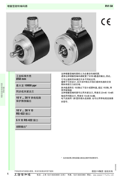
ø48 30˚
ø42 60˚
电气连接
信号 GND Ub A B A B 0 0 Ub Sens 报 警 屏 蔽 NC GND Sens
电 缆 Ø7.8 mm, 12芯 连接器 9416, 12针
白
£ 25 gcm²
£ 25 gcm²
£ 25 gcm²
£ 1.5 Ncm
£ 1.5 Ncm
£ 1.5 Ncm
40/10 N 在最大速度. 6000 min-1/ 最大 . 12000 min-1
60/20 N 在最大速度. 6000 min-1/ 最 大速度. 12000 min-1
40/10 N 在最大速度. 6000 min-1/ 最大 . 12000 min-1
25 % ± 10 %
0 0
附件
型号
附 件
命名/规定特性
订货代码
D1: Ø10 mm, D2: Ø10 mm
9401
连轴器
D1: Ø10 mm, D2: Ø10 mm D1: Ø10 mm, D2: Ø10 mm
9404 9409
D1: Ø10 mm, D2: Ø10 mm
KW
3 x 120˚
增量型旋转编码器 RVI 58
3 x 120˚
RVI 58
外形尺寸
(76)
22
ø48
0.05 A
20 10
46
-0.01 -0.02
ø58
A
ø10
ø36f8
54
0.2 A
夹紧法兰
0.05 A
10 4 3 3
(66) (52) 46
德国亨士乐编码器
德国亨士乐编码器Hengstler德国亨士乐编码器产品说明1、增量式编码器型号有:RI30-O/RI32-O/RI36-O/RI38-O/RI41-O/RI42-O/RI58-O/RI59-O/RIS58-O/RX70-I/RI36-H/RI58-H/RI58-D/RI76TD/RIS58-H。
型号具体有:RI58-D/600EF.47IB,RI41-O/200ER.11KB,RI58-O/1024ES.41RD,RI58-O/1024EK 42KB,RI58-0/0250AK.42TD,RI-58-D/600EF 47IB2、绝对值式编码器型号有:RA58,RA59,TX70TS,RA58(with SSI编程),RA58(带并行接口) ,RA58(with InterBUS),RA58(with CAN),RA58(with DeviceNet),RA58(with ProfiBUS),RA58(with SUCOnet);3、新型绝对式编码器AC58系列。
可以完全兼容RA58系列使用,功能更为强大。
AC58的型号格式为:AC58/0360 A 1 0 K S C O (单圈)AC58/1213 E K.42 DP Z (多圈)型号具体有:AC58/1212.EK72 PBB,AC58/0013EK.72SGB,AC58/1213EK 42 SGB,AC58/0013EK42SGB,AC58/1213EK 42 DPZ,AC58/0013EK 42D 9Z;增量式编码器RI 58-T/1000EG42KB:轴径为6/7/10/12mm;外径为58mm;1~10000线;直流10~30V 供电;形式各异的安装法兰;具有高防护等级可选IP64和IP67;具有多种输出方式可选(推拉输出、推拉互补输出、RS422输出、等等)。
增量式编码器RI 58-O/360EA42KB:轴径为6/10mm;外径为58mm;1~10000线;直流10~30V供电;形式各异的安装法兰;具有多种输出方式可选(推拉输出、推拉互补输出、RS422输出、等等)。
- 1、下载文档前请自行甄别文档内容的完整性,平台不提供额外的编辑、内容补充、找答案等附加服务。
- 2、"仅部分预览"的文档,不可在线预览部分如存在完整性等问题,可反馈申请退款(可完整预览的文档不适用该条件!)。
- 3、如文档侵犯您的权益,请联系客服反馈,我们会尽快为您处理(人工客服工作时间:9:00-18:30)。
EAB50B8-GR6PPR-1024编码器简介
应用行业: 一. BEN 绝对值编码器的常规外形:38MM,58MM,66MM,80MM.100MM.
二. BEN 绝对值编码器分为:单圈,多圈。
三. BEN 绝对值编码器按原理分为:磁绝对值编码器,光电绝对值编
码器
四. BEN 绝对值编码器出线方式分为:侧出线,后出线
五. BEN 绝对值编码器轴分为:6MM,8MM,10MM,12MM,14MM,25MM.
六. BEN 绝对值编码器分为:轴,盲孔,通孔。
七. BEN 绝对值编码器防护分为:IP54-68.
八. BEN 绝对值编码器安装方式分为:夹紧法兰、同步法兰、夹紧带
同步法兰、盲孔(弹簧片,抱紧)、通孔(弹簧片,键销)
九. BEN 绝对值编码器精度分为:单圈精度和多圈精度,加起来是总
精度,也就是通常的多少位(常规24位,25位,30位,32位。
)。
十. BEN 绝对值编码器通讯协议波特率:4800~115200 bit/s,默认为
9600 bit/s。
刷新周期约1.5ms ★精芬机电传感器 * 机床 * 航天航空、 * 造纸印刷、 * 水利闸门、 * 纺织机械 * 灌溉机械 * 军工设备 * 食品机械 * 钢铁冶金设备 * 机器人及机械手臂 * 港口起重运输机械 * 精密测量和数控设备
EAB50B8-GR6PPR-1024编码器 外形尺寸
EAB50B8-GR6PPR-1024编码器技术参数
BEN编码器的发展,从增量值编码器以转动时输出脉冲,通过计数设备来计算其位置,当编码器不动或停电时,依靠计数设备的内部记忆来记住位置。
这样,当停电后,编码器不能有任何的移动,当来电工作时,编码器输出脉冲过程中,也不能有干扰而丢失脉冲,不然,计数设备计算并记忆的零点就会偏移,而且这种偏移的量是无从知道的,只有错误的生产结果出现后才能知道。
解决的方法是增加参考点,编码器每经过参考点,将参考位置修正进计数设备的记忆位置。
在参考点以前,是不能保证位置的准确性的。
为此,在工控中就有每次操作先找参考点,开机找零等方法。
这样的方法对有些工控项目比较麻烦,甚至不允许开机找零(开机后就要知道准确位置),于是就有了绝对编码器的出现。
BESM58系列绝对编码器光码盘上有许多道光通道刻线,每道刻线依次以2线、4线、8线、16线。
编排,这样,在编码器的每一个位置,通过读取每道刻线的通、暗,获得一组从2的零次方到2的n-1次方的唯一的2进制编码(格雷码),这就称为n位绝对编码器。
这样的编码器是由光电码盘的机械位置决定的,它不受停电、干扰的影响。
详细了解编码器可随时致电021上海39536219精芬机电 ,编码器专家。
BEN绝对编码器由机械位置决定的每个位置是唯一的,它无需记忆,无需找参考点,而且不用一直计数,什么时候需要知道位置,什么时候就去读取它的位置。
这样,编码器的抗干扰特性、数据的可靠性大大提高了。
BEN编码器从单圈绝对值编码器到多圈绝对值编码器BESM58旋转单圈绝对值编码器,以转动中测量光电码盘各道刻线,以获取唯一的编码,当转动超过360度时,编码又回到原点,这样就不符合绝对编码唯一的原则,这样的编码,只能用于旋转范围360度以内的测量,称为单圈绝对值编码器。
如果要测量旋转超过360度范围,就要用到多圈绝对值编码器。
BEN编码器上海精芬机电生产厂家运用钟表齿轮机械的原理,当中心码盘旋转时,通过齿轮传动另一组码盘(或多组齿轮,多组码盘),在单圈编码的基础上再增加圈数的编码,以扩大编码器的测量范围,这样的绝对编码器就称为多圈式绝对编码器,它同样是由机械位置确定编码,每个位置编码唯一不重复,而无需记忆。
多圈编码器另一个优点是由于测量范围大,实际使用往往富裕较多, 这样在安装时不必要费劲找零点, 将某一中间位置作为起始点就可以了,而大大简化了安装调试难度。
多圈式绝对编码器在长度定位方面的优势明显,已经越来越多地应用于工控定位中。
