LRT-ZT2型使用说明书
Carl Zeiss Planar T 2 80 64 镜头说明书

Planar® T*2/80CONTAX® 645The Carl Zeiss Planar® lens is the most successfulcamera lens design ever created. This nearlysymmetrical layout provides the lens designer withnumerous means to correct aberrations extraordinarilywell, even for wide open apertures. The ideal basis forhigh-performance lenses with great color correction,high speed, flat image plane (this is where the namecomes from) and low distortion. The Planar® design isthe basis for nearly all professional ’workhorse’lenseson earth and in space today.At f/2 the Planar® T* 2/80 lens is the fastest optic inthe Contax® 645 system. There is no faster Planar®lens in medium format photography anywhere. Even atfull aperture the performance of the Planar® T* 2/80lens is so high that professional quality images arereached.Especially so since the Contax® 645autofocus provides for quick and accurate focusing,where manual focusingwould have been too slow or not accurate enough forf/2. So the Planar® T* 2/80 lens is the ideal tool forhandheld photography with decent shutter speeds atlow light levels, like in people photography indoors,celebrity portraits, wedding coverage and similardemanding tasks.With its focal length of 80 mm the Planar® T* 2/80lens records an image with a perspective (sizerelationship between foreground and background) thatis pretty much the way we see the scene with our eyes,like a fast 50 mm lens on a 35 mm SLR. So it is suitedfor almost any task in general photography, whichmakes it a powerful and versatile standard lens in theContax® 645 system.Preferred use: all-purpose, travel, editorial, people,celebrities, candid weddingsCat. No. of lens:10 22 19Entrance pupil*:Number of elements:6Position:40.1mm behind the first lens vertex Number of groups:5Diameter:39.9mmMax. aperture:1:2Exit pupil*:Focal length:80.0mm Position:27.8mm in front of the last lens vertex Negative size:41.5 x 56mm Diameter:45.2mmAngular field 2w:47°Position of principal planes:Mount:Contax 645 Mount H:47.1mm behind the first lens vertexFilter connection:screw-in type, thread M72x0.75H':20.0mm in front of the last lens vertex Focusing range:infinity to 0.7m Back focal distance*:60.0mmAperture scale: 2 - 2.8 - 4 - 5.6 - 8 - 11 - 16 - 22Distance between firstWeight:approx. 524 g and last lens vertex:55.0mm*at infinityPerformance data:Planar® T* 2/80Cat. No. 10 22 191. MTF Diagramsimage center - is entered in mm on the horizontal axis of the graph. TheTransfer Factor) is entered on the vertical axis. Parameters of the graph are the spatial frequencies R in cycles (line pairs) per mm given at the top of this page.The lowest spatial frequencycorresponds to the upper pair of curves, pair. Above each graph, the f-number k is given for which the measurement was made. "White" light means that the measurement was made with a subjectillumination having the approximate spectral distribution of daylight.Unless otherwise indicated, theperformance data refer to large object distances, for which normalphotographic lenses are primarily used.2. Relative illuminanceIn this diagram the horizontal axis gives the image height u in mm and thevertical axis the relative illuminance E, both for full aperture and a moderately and natural light decrease.3. Distortionon the horizontal axis in mm. Thethe relevant image height. A positive value for V means that the actual image point is further from the image center than with perfectly distortion-free imaging (pincushion distortion); a negative V indicates barrel distortion.Subject to change.Printed in Germany 12.07.2001Carl ZeissCamera LensesD-73446 OberkochenTelephone ++49-7364-20-6175Fax ++49-7364-20-4045eMail:**************http://www.zeiss.de/photo。
生命回顾疗法在老年人中应用的研究进展

生命回顾疗法在老年人中应用的研究进展冯挽1,田素斋1*,张珠珠21.河北医科大学第二医院,河北 050004;2.河北省人民医院Research progress on the application of life review therapy in the elderlyFENG Wan, TIAN Suzhai, ZHANG ZhuzhuThe Second Hospital of Hebei Medical University, Hebei 050004 ChinaCorresponding Author TIAN Suzhai, E⁃mail:******************Keywords life review therapy; the elderly; mental health; meaning of life; level of hope; quality of life; review摘要对生命回顾疗法的概念内涵、理论框架、评价指标、实施应用和国内外研究现状及其对老年人的影响进行综述,以期为生命回顾疗法在老年人中进一步广泛应用提供一定的借鉴意义,从而提高老年人生活质量。
关键词生命回顾疗法;老年人;心理健康;生命意义;希望水平;生活质量;综述doi:10.12102/j.issn.1009-6493.2024.07.014据第七次全国人口普查数据显示,我国60岁及以上人口占18.70%,比2010年人口普查上升5.44%,其中65岁及以上人口占13.50%,比2010年人口普查上升4.63%[1]。
2020年开始,我国已经步入严重老龄化阶段;预计2050年,我国将步入超高老龄化国家行列。
我国是世界上拥有老年人口最多的国家,尽管我国医疗卫生保障体系日趋完善,但老龄化形势严峻,老年人因身体老化而带来的心理变化需要引起全社会的密切关注,并对其进行有效的心理评估及干预。
老化不仅会影响老年人的身体机能,也会对其在心理和社会层面产生直接的影响[2]。
LRT-K-3说明书2

LRT-K-3型阀门定位器使用说明一、数码管显示正常自动控制情况下数码管显示当前阀位输出值的百分比值,在关到位和开到位时,关位和开位指示灯会处于常亮状态。
在进入设定状态后数码管显示菜单项的符号。
丢信时显示丢信状态信号。
二、一键设定长按上翻键+设定键3S松开进入自动行程设定状态。
首先数码管显示open符号执行器自动执行关,到位时停止,保存关位值。
延时一段时间后,执行器自动执行开。
数码管显示clos符号到位时自动停止,保存开位置。
完成自动标定后自动推出标定状态。
(注意:自动设定行程时执行器应处于中间位置,一面设定行程误差增大。
)三、菜单设定按确认键3S快速进入菜单设定。
(注意:按确认键抖动或连续两次将会进入丢信动作子菜单,按设定键退回二级菜单即可。
)设定菜单共有12项,可通过上翻键和下翻键来选择要设定的菜单选项。
1.数码管显示闪烁的1per符号表示丢信动作设定菜单项,这是可以按确认键进入丢信动作子项设定,子项内有三个选项分别是丢信关数码管显示CLOS,丢信开数码管显示OPEN,丢信保位数码管显示HOLD。
在通过上翻键和下翻键来选择要设定丢信菜单子项。
选中后按确认键丢信动作项菜单就设定好了。
按设定键返回上一级菜单,设定其他菜单选项。
2.按下翻键数码管显示闪烁的CONf符号表示正反作用设定菜单项。
按设定键进入正反作用设定子项,子项内有两个选项分别是正作用选项数码管显示JUSF符号,和反作用选项数码管显示CUrn符号,通过上翻键和下翻键来选择要设定正反作用菜单子项。
按确认键来保存设定后的正反作用子项。
完成设定后按设定键返回上一级菜单。
继续其他菜单项。
3.按下翻键数码管显示闪烁的Lin,符号表示控制信号低端4mA设定菜单项。
这时给定控制低端信号4m A按确认键来保存低端控制信号值,这时显示符号0000.(注意:如果没有给定信号,数码管显示LOSE符号。
)完成后按设定键返回上一级菜单,继续设定其他菜单项。
4.按下翻键数码管显示闪烁的HIn符号表示控制信号高端20m A设定菜单项。
LRT-T3使用说明书

三、 输入输出全光电隔离,可承受 2000V 浪涌电压冲击。 四、 可扩展液晶显示,或触摸按键控制,或磁控旋钮开关控制。常
规可实现面开盖调试。
五、 本模块最大控制三相电机功率为 800W。如超出功率范 围可扩展大功率固态继电器,或交流接触器控制。
设定菜单共有13项可通过sel数码管显示闪烁的l10或l11或l12符号表示丢信动作设定菜单项这时可以按上翻或下翻键进入丢信动作子项设定子项内有三个选项分别是丢信关数码管固定显示l10丢信开数码管固定显示l11信保位数码管固定显示l12
LRT‐T‐3 三相电动执行器智能控制模块
操 作 说 明 书
温州市隆睿特自控仪器有限公司
注意:1 接入限位开关为常闭点接入,也可电子限位, 这时需短接模块限位接入端口。温度开关不接时需短接 模块温度输入端。 注意:2 限位开关和电机转向接线电位器两端接线,需 要一致,否则不能正常控制或标定。
突破 1、集成一体化控制,无需外接交流接触器、固态继电器等
驱动配件。内部一体化三相电机正反转厚膜电路直接驱动三相电动机 无触点无火花通断控制,具有寿命长、无干扰等优点,简化接线方式。
突破 2、内部具有相序识别纠正功能,外部接线无需考虑相序。
具有电机缺相保护功能,三相电缺相时有效的保护电机不被烧毁。
突破 3、该模块具有扩展功能,可扩展液晶显示屏,霍尔操作旋
(5) 按 SEL 键数码管显示闪烁的 L5‐l 符号表示反馈信号低端 4mA 设定菜
单项。按上翻或下翻键进入低端反馈 4mA 信号设定。这时按上翻键一次反
馈信号 4mA 会以 0.02mA 增加,按下翻键一次会以 0.02mA 减小。直至满
TW-2自动化驼峰操作手册

TW-2 型驼峰自动控制系统 操作手册
北京全路通信信号研究设计院 北京 2000.3
北京全路通信信号研究设计院驼峰二室
目
录
1Байду номын сангаас
前言 ............................................................................................................................................. 6
2.1.1 调车计划的储存 .................................................................................................................. 8 2.1.2 调车计划的检查和修改 ...................................................................................................... 9
2.3 调车作业办理 ....................................................................................................................... 14
2.3.1 与溜放作业的冲突 ............................................................................................................ 14 2.3.2 以调车线为始终端的情况 ................................................................................................ 15 2.3.3 进路上的减速器 ................................................................................................................ 15 2.3.4 仅可办理长调车进路的情况 ............................................................................................ 15 2.3.5 分路道岔区调车进路的特点 ............................................................................................ 15 2.3.6 调车线出岔........................................................................................................................ 15
ZEISS i.Terminal 2 快速指南说明书

// SOFTWAREMADE BY ZEISSi.Terminal® 2 – Quick Guide Software applicationfor acquisition of the centration datafor precision lenses.Contents1Preparation of measurement (2)2Measurement / image capture (3)2.1Commencing measurement (3)2.2Positioning the customer (4)2.3Taking the front image (4)2.4Taking side image (5)3Centration data acquisition (6)3.1Measuring back vertex distance and mounting lens angle (6)3.2Determining the centration point position (7)3.3Selection of the lens type, the frame type and activation of theautocorrect mode (7)3.4Saving, post-processing and printing results ........................................... 91Preparation of measurement•If possible, remove the demo lenses from the selected frame to avoid reflections. •Adapt the selected frame anatomically.•Place the calibration tool on the frame and center it.Calibration tool with frame•Ask the customer to put on the frame.•Check that the calibration tool is still centered on the frame.Calibration tool centered Calibration tool displacedEN_20_070_7300I i.Terminal® 2 | 22Measurement / image capture2.1Commencing measurement•Start mobile on the iPad and touch the Customer tile in the main menu. •Select the customer from the overview (2) or create a new customer (1).Customer Menu•Create a new container (1) for the consultation or, if necessary, use an existing one (2).21Customer module The module appears.•Touch in the menu bar.Summary moduleThe module appears.1Centration moduleHint:Touch the i.Terminal 2 tile (1) in order to change over to Image capture modefrom i.Terminal 2 via iPad.EN_20_070_7300I i.Terminal® 2 | 3EN_20_070_7300I i.Terminal ® 2 | 42.2 Positioning the customer• First, carefully fit the customer with the selected frame.• Ask the customer to put on his/her frame together with the centered calibration tool such ashe/she would do so later.The customer must be located in a visual distance from 50 cm to 100 cm from the i.Terminal 2 in a straight line in front of the device.Natural posture, as usualUnnatural postureHint:Show the customer how to assume a natural, relaxed posture in front of i.Terminal 2. If the customer has difficulties in assuming a natural posture, ask him/her to standnext to the device and look straight ahead while you adjust the height of the device.•Adjust the height of the camera by means of the button until the customer's eyes focusthe center of the rectangle. Accordingly, the frame and the calibration tool appear on thescreen in the highlighted area.•If the customer turns his/her head in an unnatural fashion, reposition the customer.Correct head postureIncorrect head postureHint:Use the floor marking supplied with the equipment to correctly position and align the customer.Watch the customer and ensure that he/she assumes his/her habitual head and body posture during the measurement.2.3 Taking the front image• Ask the customer to focus the red cross.• Touch Image capture to record the front image.After capture has been triggered, an image or a series of images is captured automatically. • Select the best of the photos taken and touch.Front imageEN_20_070_7300I i.Terminal ® 2 | 5Checking the quality of the measurement• Check that the red crosses coincide with the black-and-white calibration marks. Otherwise,take a new photo.Hint:Touch Cancel to discard the photos and return to image capture mode.Correct front image with calibration marks.•To measure the additional parameters Back Vertex Distance and Mounting Lens Angle, touchoptionally Side image. • If you do not want to perform this measurement on the side image, touch.• Specify the manually measured back vertex distance (BVD) or accept a suggested value.Acknowledge by touching Apply .Adjusting BVD2.4 Taking side image• Ask the customer to turn by 90° so that the calibration tool is visible and not covered by thewhite rectangle.• Touch Image capture to record the side image.Once recording has been triggered, a photo is taken automatically. • Touch.Side imageChecking the quality of the measurement• Check that the red crosses coincide with the black-and-white calibration marks. Otherwise,take a new photo. Hint:Touch Cancel to discard the photos and return to image capture mode.Now you have completed the image capture process.Correct side image with calibration marks.Now, i.Terminal 2 prepares the front and side images for acquisition of the centration data and changes over to Centration data acquisition mode.EN_20_070_7300I i.Terminal ® 2 | 63 Centration data acquisition• Now you can start to evaluate the captured images to determine the individual centrationdata. Hint:The handleis used in all steps to position the measuring marks.3.1Measuring back vertex distance and mounting lens angle• Position the red mark on the front of the cornea using the handle.• If the cornea is covered by the frame side piece, measure the back vertex distance manually.Measuring back vertex distanceMeasuring mark positioned• To measure the mounting lens angle, touch Wrap angle .• Position the red measuring mark on the front side of the outer rim of the frame.Measuring mounting lens angleMeasuring mark positioned• Touch to continue.EN_20_070_7300I i.Terminal ® 2 | 73.2Determining the centration point positionHint:For evaluation, commence with the right eye.To facilitate detection of the pupil during centration, you can use the zoom and contrast feature (rotation feature), if required.• Adjust the auxiliary frame for the frame via the handles so that all four lines are in contactwith the inner edge of the frame.Adjusting auxiliary frame for spectacle frameAuxiliary frame adjusted• To continue, touch.•Move the handleto adjust the measuring outline so that the circles are concentric to thepupil center (centration point).Right-hand centration point positionTracking right-hand centration point position and frame• To continue, touch .• Repeat positioning of the auxiliary frames and the pupil center for the left-hand side.• To continue, touch .• Adjust the pupil center analogously for the left-hand eye.• You can record the shape of the lens at choice on the left or right side. To this effect, touchFrame tracing . • Use the handle to adjust the form element to the inner contour of the lens shape.Recording the lens shapeLens shape recordedThe Auto-y dialog appears.• In the following dialog, transfer the measured mounting lens angle or correct it manually.Transfer or correct measured mounting lens angle.Hint: The Auto-y dialog is only visible if the function Auto-y is activated.• Acknowledge the appropriate position by touching Apply .3.3Selection of the lens type, the frame type and activation of the autocorrect mode• Select in the dropdown list Lens type or Frame the type of lens or frame.EN_20_070_7300I i.Terminal ® 2 | 8• Using the handles displayed , correct, if necessary, the setting for the fitting height (y)and the progression length (Framefit).Select lens type and lens frame and activateautocorrect feature Auto Correction .• A slight rotation of the customer's head during image capture can be compensated via theautocorrect feature Auto Correction . To this effect, tick off.Activating autocorrect feature• To continue, tap .• Select the raw glass shape via the dropdown list Type .Determining the raw glass diameter• Select the size of the raw glass via the Table Size . The selected size is symbolized by greenrings. • To continue, tap.The complete centering data are displayed.Summary of centration data and frame dataHint: Tap Back in order to perform any necessary corrections.3.4Saving, post-processing and printing results•In the summary of the centration and frame acquisition data, tap Save and exit to save thecentration data.The data is saved and mobile returns to the Centration module.Centration is thus complete.Centration module with an overview of the centration and frame dataHint: Tap the Centration pictures tile to re-start centration for the picture takenpreviously (front image).Hint: For all subsequent steps and supplementary explanations, please refer to theQuick Guide mobile.EN_20_070_7300I i.Terminal® 2 | 9E N _20_070_7300I i .T e r m i n a l ® 2 S u b j e c t t o c h a n g e i n d e s i g n a n d s c o p e o f d e l i v e r y a n d a s a r e s u l t o f o n g o i n g t e c h n i c a l d e v e l o p m e n t .Carl Zeiss Vision GmbH Turnstrasse 27 73430 Aalen GermanyPhone: +49 7361 598 5000 Fax: +49 7361 591 480Email:********************.com /vision。
DTⅡ型固定式带式输送机使用说明书..

DTⅡ型固定式带式输送机使用说明书1.用途:DTⅡ型固定式带式输送机(以下简称DTⅡ型)由于输送量大、结构简单、维护方便、成本低、通用性强等优点广泛地在冶金、矿山、煤炭、港口、电站、建材、化工、轻工、石油等行业中用来输送散状物料和成件物品。
根据输送工艺要求,单机输送,也可以多台或与其它输送机组成水平或倾斜的输送系统。
DTⅡ型在环境温度-25~+40℃的范围内使用,输送物料的温度在50℃以下,对于有耐热、耐寒、防水、防腐、防爆、阻燃等条件,应另行采取相应的防护措施。
2.技术特征和技术参数:2.1、DTⅡ型可输送物料容量在2.5t/m以下;2.2、按带宽分为:500、650、800、1000、1200、1400、1600、1800、2000、2200、2400等11种;2.3、按驱动功率分为:1.5、2.2、3.0、4.0、5.5、7.5、11、15、18.5、22、30、37、45、55、75、90、110、132、160、200KW等20种。
2.4、按带速分为:0.8、1.0、1.25、1.6、2.0、2.5、3.15、4.0、(4.5)、5.0、(5.6)、6.5m/s等12种。
此外还有0.3m/s的带速系手选带式输送机专用;本系列输送能力见表1,表中输送能力是按水平输送,动堆积角为20°,托辊槽角为35°的条件下计算出的。
表1 带速、宽度与输送能力的匹配关系2.5、输送机允许输送的物料块度取决于带宽、带速、槽角和倾角,也取决于大块物料出现的频率。
各种带宽适用的最大块度,本系列推荐按表2选取。
当输送硬岩时,带宽超过1200 mm后,一般应限制在350 mm。
而不能随带宽的增长而加大。
3.结构概述3.1整机布置:DTⅡ的整机布置应有设计者根据物料输送工艺及其它要求进行主参数选择及计算后,选用本系列的各个部件组成一台完整的输送机。
制造厂按总图或部件清单生产供货,设计者应对整机的主要性能负责,制造厂应对部件本身的性能及质量负责,一般整机布置有下面几种形式(见图1)。
助爬器CA-2D说明书(A5)20120807最终版(1)

3S Lift助爬器操作使用说明书Operation Instruction Manual of 3S Lift Climbing Aid System中际联合工业技术(北京)有限公司3S Lift, Division of Ficont Industry Inc.3S Lift助爬器操作使用说明书Operation Instruction Manual of 3S Lift Climbing Aid System中际联合工业技术(北京)有限公司3S Lift , Division of Ficont Industry Inc.地址:北京市通州区宋庄佰富苑工业区6号邮编:101118Add:No.6 Baifuyuan Industry Zone, Songzhuang, Tong Zhou District, Beijing, China, 101118电话Tel:86 010-********传真Fax:86 010-********网址Web:邮箱E-mail:sales@24小时服务热线24-Hour service hotline:40000-24580 版本Version:F3S Lift助爬器操作使用说明书中际联合工业技术(北京)有限公司目录1. 符号说明 (2)2. 注意事项 (4)3. 产品描述 (8)3.1产品概述 (9)3.2产品原理及使用 (10)3.3特点 (11)3.4产品技术参数 (12)3.5助爬器的组成 (13)4. 操作方法 (18)5. 保护身体的安全设备 (20)6. 日常检测与维护 (20)6.1日常检查 (20)6.2保养 (21)7. 故障与维修 (23)8. 包装 (24)第1页/ 共24页3S Lift助爬器操作使用说明书中际联合工业技术(北京)有限公司1. 符号说明符号关键词意义造成的后果注意潜在的危险受伤或设备损坏安全保护穿安全服严重受伤安全手套戴安全手套严重受伤安全帽戴安全帽严重受伤第2页/ 共24页3S Lift助爬器操作使用说明书中际联合工业技术(北京)有限公司符号关键词意义造成的后果安全带系安全带严重受伤危险可能的危险受伤或设备损坏重要工作中的有效建议无有关说明第3页/ 共24页3S Lift助爬器操作使用说明书中际联合工业技术(北京)有限公司2. 注意事项危险!助爬器不适用于低于18岁或少于50公斤体重的人员,为避免发生意外,请仔细阅读操作说明书后进行操作!a)有专业设备操作技术资格的人员才能安装、操作和维护助爬器及安全设备。
徕卡TS02说明书节选
|
| ── USB- 文件管理
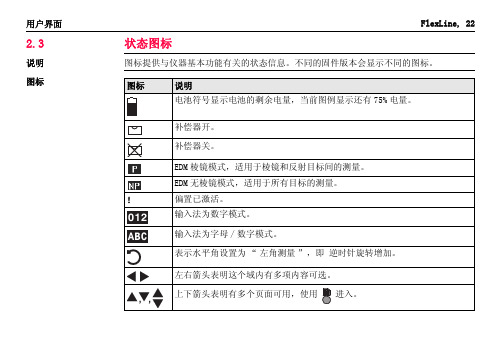
FlexLine, 266
树状菜单结构
| ── | | | | ── | | | | | | | | | | | | | | | | | ──
传输 | ── 输出数据
| ── 输入数据
设置
| ── 概述
|
| ─ 对比度 , 触发键 1, 触发键 2, 自定义键 1, ຫໍສະໝຸດ 定义键 2, 倾斜改正 , 水平角改
TSOX_002
SA
使用编码划分的水平角读数盘。
树状菜单结构
附录 A
)
树状菜单结构
树状菜单结构
取决于本地的固件版本号,菜单选项可能不同。
| ── 测量
|
|
|
| ── 应用程序
|
| ── 测量
|
| ── 放样
|
| ── 自由设站
|
| ── 参考元素
|
| ── 对边测量
|
| ── 面积 & 体积
|
| ── 悬高测量
软按键
软按键通过对应的 F1 到 F4 功能键来选择。这一节描述了系统中所使用的公共软按键的 功能。更多特定软按键会在它们出现的应用程序章节进行说明。
FlexLine, 23
用户界面 公共软按键功能
按键 -> ABC -> 012 测存 测距 EDM 坐标 退出 查找 输入 P/NP 列表 确定
后退 记录 重置 查看
对中界面会出现。否则,按 FNC 键选择整平 / 对中。 4. 移动脚架腿 (1),并转动基座脚螺旋 (6),使激光 (4) 对准地面点。 5. 伸缩脚架腿 (5) 整平圆水准器 (7)。 6. 根据电子水准器的指示,转动基座脚螺旋 (6) 以精确整平仪器。参照 " 使用电子气
TAZ II计轴设备调试手册V1.1

DTII型固定式带式输送机说明书

DTII型固定式带式输送机产品使用说明书衡阳起重运输机械有限公司1.用途、特点、使用范围1.1.DTⅡ型固定式带式输送机是通用型系列产品,是有棉帆布、尼龙、聚酯帆布及钢绳芯输送带作曳引构件的连续输送设备,可广泛用于煤炭、冶金、矿山、港口、化工、轻工、石油及机械等行业,输送各种散状物料、成件物品。
带式输送机具有运量大,爬坡能力高,运营费用低,使用维护方便等特点,便于实现运输系统的自动化控制。
1.2.输送物料的松散密度为500~2500kg/m3,输送块度见表1表1 mm注:块度系指物料最大线性尺寸1.3.工作环境温度,一般为-25℃~+40℃,对于有特殊要求的工作场所,如高温、寒冷、防爆、防腐蚀、耐酸碱、防水等条件,应采取相应的防护措施。
1.4.DTⅡ型固定式带式输送机均按部进行系列设计,选用时可根据工艺路线,按不同地形及工况进行选型设计、计算、组装成整机,制造厂按总图或部件清单生产供货、设计者对整机性能参数负责,制造厂对部件的性能和质量负责。
1.5.输送机应尽量安装在通廊内,在露天场合下,驱动站应加防护罩。
1.6.本系列产品能满足水平、提升、下运等条件。
也可采用凸弧段、凹弧段与直线段组合的输送形式。
2.主要参数(常用规格设计范围)2.1.带宽:500 650 800 1000 1200 1400mm2.2.带强:棉帆布带56N/mm·层、尼龙、聚酯帆布100~300N/mm·层,钢绳芯带st630~st2000N/mm2.3.带速:0.8、1.0、1.25、1.6、2.0、2.5、3.15、4.0、5.0m/s2.4.最大输送能力:见表2表2 带速V、带宽B与输送能力I V的匹配关系注:1)输送能力I V值系按水平运输,动堆积角θ为200,托辊槽角入350计算的。
2)表中带速(4.5)(5.6)m/s为非标准值,一般不推荐选用。
3)□已完成设计。
3.整机的典型布置3.1.DTⅡ型带式输送机的典型布置见图1。
DTII皮带机使用说明

D T I I型固定式带式输送机产品使用说明书目录一、用途、特点、使用范围1二、主要参数1三、整机的典型布置2四、部件概述 44.1、输送带4 4.2、驱动装置4 4.3、滚筒6 4.4、托辊7 4.5、拉紧装置11 4.6、机架11 4.7、头部漏斗12 4.8、导料槽12 4.9、清扫器12 4.10、卸料器134.11、电气及安全保护装置13五、安装、调试与试运转15六、操作规程与维护、保养23七、润滑24八、胀套的调整25九、随机携带文件25附件1: 滚筒用胀套参数25附件2: 滚柱逆止器用弹簧参数 26附件3: 滚筒用轴承型号 27 附件4: 缓冲托辊组的维护 28一、用途、特点、使用范围1.1 DTⅡ型固定式输送机是通用型系列产品,是以棉帆布、尼龙、聚酯帆布及钢绳芯输送带作曳引构件的连续输送设备,可广泛用于煤炭、冶金、电力、矿山、港口、化工、轻工、石油及机械等行业,输送各种散状物料及成件物品。
带式输送机具有运量大、爬坡能力高、运营费用低、使用维护方便等特点,便于实现运输系统的自动化控制。
1.2 输送物料的松散密度为500~2500kg/m3。
输送块度见表1。
注:块度系指物料最大线性尺寸1.3 工作环境温度:一般为-25℃~+40℃,对于有特殊要求的工作场所,如高温、寒冷、防爆、阻燃、防腐蚀、耐酸碱、防水等条件,应采取相应的防护措施。
1.4 DTⅡ型固定式带式输送机均按部件系列进行设计。
选用时可根据工艺路线,按不同地形及工况进行选型设计、计算、组装成整机。
制造厂按总图或部件清单生产、供货。
设计者对整机性能参数负责,制造厂对部件的性能和质量负责。
1.5 输送机应尽量安装在通廊内。
在露天场合下,驱动站应加防护罩。
1.6 本系列产品能满足水平、提升、下运等条件。
也可采用带凸弧段、凹弧段与直线组合的输送形式。
二、主要参数(常用规格设计范围)2.1 带宽:500、650、800、1000、1200、1400mm2.2 带强:棉帆布带56N/mm·层;尼龙,聚酯帆布带100~300N/mm·层;钢绳芯带st630~st2000N/mm。
通用汽车公司 Tech 2扫描工具 说明书

注意
当电池同时与车辆的12伏点烟器或电源相连时,不要将电池的两个接线端同时接上.因为此时点烟 器中的正负极可能倒置,这将会对Tech 2或车辆造成损害. 如果Tech 2的电源已接通,而显示屏仍为空白,此时点烟器中的正负极可能倒置,这将对Tech 2造 成损害.不要将DLC电缆接到车辆上.确定车辆点烟器的中心触点的电压值高于12伏且外部触点已 接地. 插入或取出PCMCIA卡之前请先关闭电源.建议不要连续取出或重复插入PCMCIA卡. 插入Tech 2之前,请将所有的卡和元件都仔细对齐. 开始使用Tech 2之前,确信所有的电缆和连接器都已连接牢固. 尝试新的程序之前,请仔细阅读说明书. RS-232和RS-485端口不能接到直流电话线上,因为Tech 2的设计不支持这种通讯方式. 放置Tech 2时不要让倾斜支架与车辆电池的接线端接触,这会造成电池短路.
1. 使用:客户只可以在最初安装该软件的计算机系统上使用此软件.未经法律授权,客户不得对该软件进行反汇编或反编译. 2. 所有权:客户同意除了物理介质所有权外,不拥有软件的任何题名或所有权.客户承认并同意该软件的版权归属及其所受的版权法 保护.客户承认并同意该软件可能由版权公告中的第三方软件供应商开发,后者有权要求客户对其任何违反和侵犯版权的行为承担 责任. 3. 终止:当通用汽车公司要求客户遵守协议中的条款,而客户在接到通知后30日内仍未做到时,公司可以终止该软件的授权许可.
图 I-4 T e c h 2 电源和电缆部件编号列表(见第四节)
命令
Tech 2会提示您通过键盘输入以下命令: 获取并查看诊断信息 选择自检 执行车辆诊断程序
ห้องสมุดไป่ตู้
数据存储
Tech 2附带一种名为PCMCIA(个人计算机存储卡业联盟)的卡,用来存储诊断程序.随着车型的不断变 化,重新编写PCMCIA卡的程序并通过RS-232连接器可以随时升级Tech 2的软件.
Raymarine TZT2BB 产品说明书

Q Optional remote controllers available for the TZT2BB?Optional remote controllers are the MCU002, MCU004 and MCU005.The MCU002 and MCU004 USB remote controllers as well as the MCU005Ethernet remote controller are compatible with the TZT2BB as well asTZTL12F/15F MFDs with software v6.21 and above. More than one MCU004/5can be connected to a single TZT2BB. Once connected to the TZT2BB or aTZTL12F/15F, the MCU004/5 can control any TZtouch2 MFD in the system. The MCU002 can only control the unit that it is connected to. In the case of theTZT2BB, you would have to have 2ea MCU002s to control both displays of theTZT2BB. Alternatively, the Android Controller App is freely available for download and can be used with any TZtouch2 MFD using a Wi-Fi connection.Click here for more information on optional controllers, MCU002/4/5.Q How many MCU remote controllers can I have on a network.MCU004s and MCU005s are limited to a max of four MCUs or combination of, per network. The MCU002 does not count towards this limit.Q Can a single monitor be used with the TZT2BB?Yes. Click here for more information.Q Can the TZT2BB use monitors with different resolutions?Yes, each processor is configurable to the connected display. For example, you can have one 24” wide screen monitor and the other could be a 17”or 19” 4:3 monitor.Q Which screen resolutions are compatible with NavNet TZT2BB?Each side is fully independent.1920 x 1080 (16:9, FHD)1280 x 1024 (5:4, SXGA)1024 x 768 (4:3, XGA)Q Do I need to use only touch screen monitors?No. Non-touch monitors can be used along with an optional remote controller,MCU002/4/5. Click here for more information.Q Can standard PC monitors be used with TZtouch2 MFDs for remote displays?Yes. While standard monitors can be used, it is recommended that the monitor be tested with the TZT2BB before it is mounted to see if it is compatible or not.The TZT2BB does not support proprietary drivers, such as 10-point touchfeatures. The TZT2BB supports dual point touch only. Any touch monitor thatrequires that a driver be loaded into the TZT2BB will not work. The TZT2BB can use standard 4:3 or widescreen PC monitors that are either HDMI or DVI (with an adapter plug) compatible. Non-marine monitors are not recommended foroutside installations or in high bright areas. Also consider night time viewing for installations using non-marine grade monitors.Q How many NavNet TZtouch2 MFDs are allowed in one network?At this time, any combination of up to six (6) TZtouch2 (v6.21 and higher) MFDs are allowed in one network. One TZT2BB counts as two MFDs. If a MaxseaExplorer or Nobeltec PC is included, it is counted as one MFD in the network.Q Does the TZT2BB have a built in GPS antenna?No. The TZT2BB does not have a built in GPS receiver/antenna since it will be mounted in a location that would not reliably pick up GPS signals. It will benecessary to add a NMEA2000 sensor, such as the GP330B to the network.Q What type of connections does the TZT2BB have?Q What connections are available on the Multi-cable port?The Multi-cable has connections for an optional power switch, NMEA0183 output, external buzzer and event switch. It has 11 color coded wires.Q Does NavNet TZtouch2 have built in NMEA0183 functionality?Yes. TZT2BB has a single NMEA0183 output port. TZT2BB does not have anNMEA0183 input port.Q What NMEA 0813 Sentences can the TZT2BB output?The TZT2BB can output the following NMEA0183 sentences. All sentences use GP as the talker.Q How many Ethernet ports does the TZT2BB have?Three external Ethernet ports are available.Q Can I also add additional Ethernet Hubs/switches as well? What about a generic off the shelf switch.The TZT2BB does not require a special Ethernet Hub. While we recommend the Furuno HUB101, any standard 100MB Ethernet Hub/Switch is compatible withthe network. If a HUB101 is not used, a Gigabit Switch is recommended.Q How many Ethernet hub/switches can I have on my network?Max number of Ethernet Hubs or switches on a NavNet network is three. TheTZT2BB counts as one switch if more than one (1) port is used.Q I have limited dash space. Do I have to install the PSD003 switch box?No. You can utilize the power on switch wires of the Multi-cable. Connect thepurple and brown wires to a momentary contact switch (not provided). You could also mount the PSD003 in an out-of-the-way location and still install amomentary contact switch in a more convenient location.QQ Q Q Q Q Q Q Are standard Microsoft USB Mice and Pointing Devices compatible with theTZT2BB?Yes, as long as a special driver is not required. You cannot load any drivers into the TZT2BB. You can perform almost every function using a mouse trackball and wheel. The only function that is not supported is pan and tilting the plotter in 3D mode. That is only supported by the two-finger touch operation.Can I use a standard USB keyboard?No. TZT2BB does not support a USB keyboard.Can additional USB devices be connected using a generic USB Hub?Yes.What video inputs are available on the TZT2BB?The TZT2BB has one (1) HDMI IN, two (2) Analog "PAL" inputs and up to four (4) Axis IP cameras are supported.TZT2BB also supports two Axis Quad Video servers.What IP Cameras is the TZT2BB compatible with?TZT2BB is currently compatible with most Axis (H.264) IP Cameras or cameras that also support the Axis IP camera CODEC. TZT2BB also supports two Axis Quad Video servers.Does the TZT2BB offer FLIR camera integration?Yes. Further information on compatible models can be found here.Can FLIR M-Series Cameras be controlled from the TZT2BB?Yes. Configuration information can be found in a dedicated document on TZtouch2 product pages at or by clicking here.I currently have a NavNet 3D MFDBB system on my boat and I would like to upgrade to the TZT2BB. What items of my current system can I reuse?Radar SensorsThe DRS radar sensor that was connected to your NavNet 3D system is compatible with the TZT2BB. The DRS software might need to be updated for it to work with a TZtouch/2 MFD. We recommend that this is done while still connected to the NavNet 3D MFD. Current software can be found under the software tab for the DRS radar sensor. If the DRS radar sensor was powered via the MFD, a DRS power supply needs to be added. Depending on the DRS model this will be either a PSU017 or PSU012.SoundersThe DFF1 and DFF3D are compatible with the TZT2BB. The dip switch settings of the DFF1 or DFF3 will have to be changed to a static IP address.MCU001 (MFDBB Controller)The MCU001 needs a modification kit to be compatible with the TZT2BB or any TZtouch2 MFD. This kit includes software for the MCU001, new rubber keypad, new bezel, two 5m Ethernet cables and a POE injector. Part # for the kit is 001-506-900-00Q Overview of procedures to update a NavNet 3D MFD system to a TZT2BB system •Check that legacy DRS software is at V1.16 or higher•If the DRS radar sensor is powered from the NavNet 3D MFD than anappropriate external DRS power supply must be added.•PSU012/013 must have XH connector jumper installed on J7. This sends power to radar without using power-sync•Change IP address mode switches on sounders to Down/Up/Up/Down for TZT2BB connections.•MUST turn off all Power-sync switches in the HUB101. Power-sync was only required in NN3D architecture. Leaving this on WILL cause problems.•Chart licenses do not transfer to upgraded systems. New chart unlock codes need to be purchased for any “For pay” charts. You cannot transfer chartunlock codes from the NavNet 3D system to a TZtouch2 system.•Convert MCU001 to MCU005 using mod kit part # 001-506-900-00Q Which charts are pre-installed on the 256GB Micro SD-Card in the TZT2BB?The 256GB Micro SD-Card included with the TZT2BB card contains every NOAA Raster, NOAA Vector, C-MAP Vector, and Navionics Vector chart file in the entire Mapmedia Library for all of North, Central and South America. The entireWestern Hemisphere chart file is preloaded. Only customers wishing to accessadditional satellite photo areas or charts on the other side of the world will need to add more chart files to their system. Locked chart areas will need to bepurchased from an Authorized Furuno Dealer. Once chart areas are purchased, they can be automatically unlocked by connecting the TZT2BB to the Internet.Alternatively, the charts can be manually unlocked by entering the chart license unlock codes.Q Does the TZT2BB have a built in sounder?Yes. The TZT2BB has the same built-in RezBoost sounder as a TZTL12F/15F. You may also add a DFF1-UHD TruEcho CHIRP Fish Finder, DFF3D, BBDS1 or DFF3. Q Does the TZT2BB support the new BBWX4 Sirius/XM marine weather/audio receiver?Yes. Both weather and entertainment audio. Click here for more info.Q Does the TZT2BB have a built-in operator’s manual?Yes. TZT2BB has a built-in operator’s guide called “eGuide.” The “eGuide” can be accessed from the home screen and is fully indexed.Q Which Smart phone/Tablet Apps are compatible with the TZT2BB?TZT2BB is compatible with the Android/Apple Controller App, Android/Apple iOS Viewer Apps, and the Android/Apple iOS remote app.Q Does the TZT2BB have an internal LAN antenna for Wi-Fi?Yes, while the TZT2BB does not have an internal GPS antenna it does have aninternal LAN Wi-Fi antenna. Depending on location of the TZT2BB, an externalWi-Fi router might be required for extended ranges and better connectivity.Q Are NavNet 3D networks compatible with NavNet TZtouch2?No. TZT2BB and TZtouch2 MFDs are not compatible with NavNet 3D. NavNet 3D and TZtouch2 MFDs cannot exist together on the same network.Q Can Furuno commercial radars be connected to a TZT2BB?Yes. The FAR2XX7, FR15X8 and FR15X3 Depending on software versions) arecompatible with the TZT2BB and TZtouch2 MFDs with software version 6.21 and above. There are some feature limitations, but basic functions are available on the TZtouch2 MFDs. Contact Furuno Tech support for more information.Q Is the TZT2BB and TZtouch2 MFDs compatible with Nobeltec TZ?TZ Professional and TZ Navigator (with Radar module) can be connected to aTZtouch2 network. The following features are available:•Chart License sharing (link a TZtouch2 System ID with Nobeltec TZ Serial Number)•Navigation Data from the TZtouch2 network (GPS, Speed, Heading, etc.)•Radar WorkSpace and Radar Overlay (with full control of the DRS Radar)•DFF1, BBDS1, DFF1-UHD or DFF3 compatibility with optional Sounder module•DFF-3D compatibility with optional PBG and DFF-3D module (requires Satellite Compass for stabilization)•Active Route and Waypoint with TZ software• A Nobeltec TimeZero PC counts as one MFD in any network of up to six (6) MFDsAlso, with the TZT2BB you can utilize the HDMI IN port along with the USBpassthrough port to view and control a Nobeltec PC using the same monitor that is connected to the TZT2BB. You can also view and control the Nobeltec PC in a quarter screen.Q Is the TZT2BB compatible with CZone Digital Switching Systems?Yes. Click here for more info on CZone and TZtouch2.Q Is TZtouch2 compatible with the Active Captain POI database?Yes. However, at this time, you can only view Active Captain POI information.You cannot login to update the POI data base or provide updates to thedatabase.Q Does the TZT2BB have to be opened during installation to attach cables, set switches, etc.?No. All connections are made using pigtail cables and are external to theTZT2BB. No switches need to be changed inside the TZT2BB.Q Can a Fusion radio be connected to the TZT2BB?Yes. The following models are compatible with the TZT2BB and all TZtouch2MFDs with software v6.21 and higher. Fusion models 700, 750, 755 and Apollo.TZtouch2 MFDs connect to Fusion radios via an Ethernet connection, not viaNMEA2000.Q If I have two DRS radar sensors in my TZT2BB system, can I display dual range radar video on both screens?Yes. You can view a different radar on a different monitor. You can also show the different DRS radar sensors in dual mode.Q TZT2BB has two different weather options. It has the built in free NavCenter weather and an optional BBWX4 SiriusXM weather receiver can be added. Can I view NavCenter weather on one display and SiriusXM weather on the otherdisplay?Yes. You can set the displays up independently of each other. You can also set both sides to display SiriusXM weather information.Rev 3-4-19。
自动永停滴定仪ZYT-2

自动永停滴定仪ZYT-2概述自动永停滴定仪ZYT-2是一种常见的测试仪器,主要用于化学实验室中进行物质浓度的测定。
它采用了先进的自动化技术,具有高精度、高效率的特点,能够精确地测定试样的浓度。
本文将详细介绍ZYT-2滴定仪的使用方法、特点以及维护技巧等内容。
使用方法安装安装ZYT-2永停滴定仪前,请确保仪器完好无损,所有部件都有安装完整。
首先将仪器放在实验台上,按下脚轮刹车将仪器固定在正确的位置,然后再连接所有电线和管道。
最后轻轻拧紧所有的插头和螺纹,确保仪器牢固可靠。
预热在进行测量前,必须对ZYT-2滴定仪进行预热。
打开电源开关,使仪器加温至设定温度,这样可以保证ZYT-2仪器在工作状态下,具有更精确的测量结果。
将试样加入滴定瓶中将试样加入滴定瓶中,并加上指示剂,如此,就可以进行滴定操作了。
注意要避免在试样中加入杂质,否则会影响测定结果。
滴定操作将试样滴入滴定瓶中,同时打开ZYT-2滴定仪,以某种预定的速率滴加标准物质,例如酸碱滴定中,加入的酸或碱的体积就是标准物质的体积,继续滴定直至指示剂显色改变,此时,读取浓度值并记录在报告中。
特点高效率ZYT-2永停滴定仪采用先进的自动化技术,可快速准确地完成滴定的操作,高效省时。
其手动预滴定和自动滴定的操作功能,使得操作更加简便,有效地提高工作效率。
高精度ZYT-2滴定仪拥有高精度的滴定技术,能够保证测量结果的准确性。
其采用先进的电子测量技术和自动悬浮校准,能够自动调整测量参数,有效地避免了人为失误,提高了测量的精度。
高度自动化自动永停滴定仪ZYT-2具有高度自动化的特点,采用了先进的数字化控制技术,包括自动滴定、自动识别终点、自动计算浓度等功能。
在滴定过程中,仪器会自动判断是否达到终点,并自动计算浓度值。
易于操作ZYT-2永停滴定仪设计简单,易于操作,且控制及显示面板较为直观。
操作人员只需简单的操作,即可完成测量操作,且结果易于获取和记录。
维护技巧ZYT-2滴定仪是一种精密化学分析仪器,因此需要定期进行维护,以保持其正常功能。
思瑞高度尺II型中文说明书
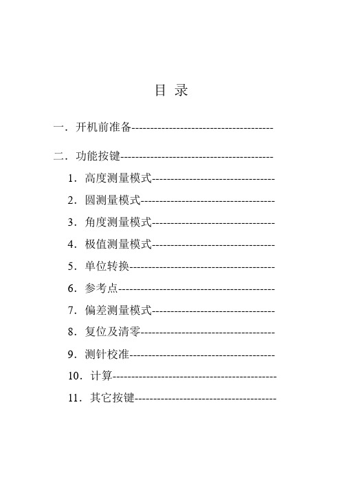
目录一.开机前准备-------------------------------------- 二.功能按键----------------------------------------- 1.高度测量模式--------------------------------- 2.圆测量模式------------------------------------ 3.角度测量模式--------------------------------- 4.极值测量模式--------------------------------- 5.单位转换--------------------------------------- 6.参考点------------------------------------------ 7.偏差测量模式--------------------------------- 8.复位及清零------------------------------------ 9.测针校准--------------------------------------- 10.计算-------------------------------------------- 11.其它按键--------------------------------------三.2D测量模式-------------------------------------- 1.2D坐标获取----------------------------------- 2.坐标平移---------------------------------------- 3.坐标旋转---------------------------------------- 4.拟合圆------------------------------------------- 5.拟合直线---------------------------------------- 6.极坐标系统------------------------------------- 7.直角坐标系统---------------------------------- 8.建造虚拟点------------------------------------- 9.返回原始坐标---------------------------------- 10.圆心-圆心距离------------------------------- 11.圆心-原点-X轴角度------------------------ 12.圆心-圆心-圆心角度------------------------ 13.圆心-圆心-X轴角度------------------------ 14.计算结果列表-------------------------------- 15.原测量值列表-------------------------------- 16.保存计算结果-------------------------------- 17.退出2D----------------------------------------四.常见问题及解决方法--------------------------- 五.保修卡--------------------------------------------- 六.各地维修点---------------------------------------一.开机准备1. 当您打开包装箱时,请您按以下清单清点物品:Pioneer高度测量仪主机1台控制器1台说明书1本测针(直径4mm) 1支工具2把校准训练块1个充电器1个M6螺丝2只以上附件如有缺少,请与您的经销商接洽。
Fixturlaser激光对中仪手册
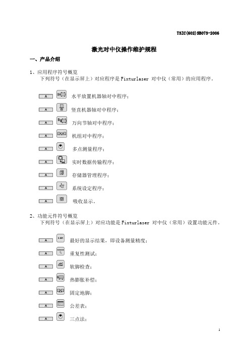
T3ZC(602)SB073-2006激光对中仪操作维护规程一、产品介绍1、应用程序符号概览下列符号(在显示屏上)对应程序是Fixturlaser 对中仪(常用)的应用程序。
水平放置机器轴对中程序;竖直机器轴对中程序;万向节轴对中程序;机组对中程序;多点测量程序;实时数据传输程序;存储器管理程序;系统设定程序;吸收显示。
2、功能元件符号概览下列符号(在显示屏上)对应功能是Fixturlaser 对中仪(常用)设置功能元件。
最好的显示结果,即设备测量精度;重复性测试;软脚检查;热膨胀补偿;固定地脚;公差表;三点法;传输功能;显示电池电压或采用外接电源的时候显示图标;对比度,分别按图标两旁的符号可以增加或减少屏幕的对比度;()背景灯开关,最后操作后背景灯可以亮5分钟(当使用外接电源时背景灯不会自动关闭);关闭系统,操作完别后,按该按钮可退出程序。
3、设备概览下列设备是Fixturlaser 对中仪(常用)设备。
DU100显示器;系统打印机;TD-M100激光发射器;TD-S100激光发射器;二、安全与维护1、电源Fixturlaser 对中仪用四节LR 20型碱性电池供电,显示单元也可以用任意外接电源供电。
当用系统进行正常的调整工作时,电池的寿命大约为24小时。
在主菜单中,电量指示器显示电池的电量。
电量低时,更换电池警告会显示在屏幕上。
打开电池盒外盖露出电池盒可以更换电池。
每个盒中有两节电池。
电池应正极朝向显示单元内部,负极朝向外盖。
也可用充电镍镉电池,但操作时间会比碱性电池时间短。
如果系统因低电量关机,更换电池或连接外部电源的时候,系统会返回到关机前的应用软件中。
不会丢失信息。
!如果设备长时间放置,应取出电池以防止损坏。
外部电源是将在显示单元串行口旁边的计算机终端与110 – 240伏墙壁开关连接一起的。
2、安全Fixturlaser 对中仪用的是激光二极管,功率输出小于1.0 mW。
激光级数为2级,在较低警告要求时使用可以认为是安全的。
WTZJ-II型机车综合无线通信设备使用说明书V2.0

WTZJ-II型机车综合无线通信设备 使用说明书V2.0杭州创联电子技术有限公司地址:杭州市西湖区万塘路30号电话:4006798001,0571‐85023055,85023155传真:0571‐85026055邮编:310013WTZJ-II型机车综合无线通信设备使用说明书 V2.0目录一、设备功能介绍 (1)二、操作显示面板介绍 (1)三、GSMR调度通信功能 (4)四、450MHz调度通信功能 (5)五、调度命令功能 (6)六、列尾连接功能 (7)七、设置和调节功能 (7)7.1、车次功能号设置、注册(或车次功能号注销) (8)7.2、运行区段选择 (9)7.3、查询通信录 (10)7.4、扬声器音量调整 (11)7.5、听筒音量调整 (12)7.6、输入客车列尾装置ID (12)7.7、维护界面 (13)7.8、状态查询 (14)7.9、屏幕亮度调整 (15)7.10、出入库检测 (16)八、手动复位功能 (22)九、打印机维护操作 (22)一、设备功能介绍WTZJ-II型机车综合无线通信设备是主机小型化的机车综合无线通信设备(以下简称“小型化CIR”),主要是针对既有机车安装空间紧张而作的小型化改进,小型化CIR在设备结构上取消了标准型机车综合无线通信设备内部集成的800MHz列尾和列车安全预警系统机车电台以及高速数据传送单元。
该设备具有如下功能:1、具有450MHz通用式机车电台的调度通信功能。
2、具有450MHz通用式机车电台承载的列车尾部风压、无线车次号、调度命令等数据信息的传输功能。
3、具有GSM-R调度通信功能。
4、具有GSM-R通用数据传输功能,根据承载业务的需要提供GPRS或电路方式数据传输链路。
5、具有《列车防护报警系统和客车列尾系统技术条件》中规定的车载电台的功能。
6、具有工作模式自动、手动转换功能和语音提示功能。
7、具有上、下行线路分别设定工作模式转换点的功能。
8、根据卫星定位信息无法确定唯一的运行线路时,具有提示并手动选择运行线路的功能。
运输机说明书2

1 输送机的传动系统: 输送机的传动系统包括双速电动机、减速器、刮板链等。双速电动机将动力传递给
减速器输入轴;通过减速器由减速器输出轴再将动力传递给链轮组件;链轮驱动封闭的 刮板链按需要的方向运行,完成输送煤炭的任务。
2 输送机组成: SGZ900/1050 型输送机主要由机头传动部、机尾传动部、机头推移部、机尾推移部、
4
SGZ1000/1050 型输送机使用说明书
194S11/02-SY
链 规 格---------------------------------------------34*126-D 紧凑链 型 式---------------------------------------------------中双链 链中心距---------------------------------------------------200mm l 卸载方式--------------------------------------------------端卸 l 紧链方式------------------------液压马达紧链、液压伸缩机尾辅助紧链
警告提示是使您引起对危险性的警惕,否则将导致受伤或死亡,如果不采取合适的预 防措施,事故将会发生。 1.3 小心!
小心提示是使您引起对危险性的小心,否则将导致人身伤害或设备损坏。这类危险性 通常是不严重的,但发展下去后果是可怕的。如果不采取合适的预防措施,甚至会发生致 命伤害。
2 提示内容 2.1 危险! 2.1.1 在输送机运行中,任何人不得跨越输送机,否则将导致受伤或死亡。 2.1.2 在采煤过程中,任何人不得站在输送机的煤壁侧,否则将导致受伤或死亡。
2
SGZ1000/1050 型输送机使用说明书
TA2中文操作手册

调试说明一. 安装注意事项1.1探杆安装探杆的插入深度务必超过管道中心线25mm,见下图.1.2 接线1.2.1电气端接线步骤:a. 打开接线盒外盖(见下图)b. 将电源线通过电气接口引入接线盒;c. 将正确电源接到TB1 端子(要确认该仪表的使用电源) ;1.) 如电源为120VAC,火线接到L1 端子,零线火线接到L2/N 端子,2.) 如电源为240VAC,一根线接到L1 端子,另一根线接到L2/N 端子,3.) 如电源为24DC,正端接到+端子,负端接到- 端子d. 将4~20mA 信号线接到TB2 端子,将正端接到A+,负端接到A- 端e. 盖好接线盒2.一体化探头端接线步骤:a. 确认电源断开;b. 将PC 板端外盖打开,参考操作手册页31 图8;c. 拧松显示板的固定螺丝,拔出显示板;d. 用1/4” 内六角扳手松开探头和变送器连接出的两个内六角固定螺 丝。
此时可以取出逻辑板和电源板;3.分体式探头端接线步骤:a. 确认电源断开;b. 将PC 板端外盖打开,c. 拧松显示板的固定螺丝,拔出显示板;d. 用1/4” 内六角扳手松开探头和变送器连接出的两个内六角固定螺 丝。
此时可以取出逻辑板和电源板;e. 探头的引出的五根线将连接到探头接线盒内分体PC 板上。
看下表 五个接线端子序号 探头引出线颜色1 白色2 兰色3 黑色4 棕色5 桔黄色线 端子 探头白色 1 温度探头兰色 2 流量探头黑色 3 接地棕色 4 加热接地橙色 5 加热f. 探头接线盒内分体PC 板上八个接线端子将与变送器内TB3 板上8 个 接线端子连接,按各电路板上端子号如下接线:分体式探头内端子序号 TB3 板上接线端子号线 远传端子 TB3接线端绿/白 线1 1白/绿 线2 2兰/白 线3 3白/兰 线4 4棕/白 线5 5白/棕 线6 6橙/白 线7 7白/橙 线7 7屏蔽线 线8 84.简单参数设置由于TA2流量计已经按照客户技术规格书的要求,在出厂前进行标定后再发往客户处.如需改变原有的量程,或者用于其它安装位置必须返厂重新进行标定.TA2的操作界面是菜单式,分为主菜单和子菜单,其中主菜单大致分为以下几个窗口,通过”上”或”下”箭头切换.第一次通电后,需要等待3~5分钟,等仪表初始化后,液晶屏显示瞬时流量时,就可以修改相关参数.如需进入子菜单请按”回车”键4.1 System Config 参数设置主要可以修改流量单位;质量流量单位;温度单位;密度单位;管径单位;面积单位;其中”flow area”是自动计算的流通面积,不需要修改.4.2 I/O Config 参数修改要修改其中的参数,需要输入密码”200”.在这个子菜单内可以修改4mA,20mA对应的值.电流输出按照”体积流量”或”质量流量”输出.4.3 Adv Config(高级设置) 默认修改密码为”200”.高级设置菜单里面可能用的参数为”install Factors”.具体公式为:A+Bv+Cv~2=实际流量 A.B.C为修正系数,v为表头显示的流量 一般把公式简化为 Bv=实际流量 所以, A.C默认为0.通过修改B就可以使得表头的读数接近实际流量值.4.4 Diagnostics(诊断菜单) 默认修改密码为”200”. 该菜单用于诊断表头和探头是否工作在正常状态.4.5 Factory Config(工厂配置参数) 默认修改密码:2005 HART 通讯菜单6.检查TA2的流量特性是否在工作范围之内目的:当TA2热式质量流量计使用一段时间后,用户总会怀疑自己的流量计还准不准,由于以前需要特殊的设备来标定,才能确定精度是否满足要求.现在可以把流量计放在办公室内,进行相关测试,从而知道流量计是否在正常工作范围内.TA2测量热传感器,并且在标定的时候热传感器和质量流量建立一定的关系.检查TA2的标定情况的一种方法是检查探头的热传感器特性是否还在控制范围内.接下来的步骤是在没有流量和模拟高流量两种情况下,检查热传感器.需要的设备:热水盆或桶(容量大约为1升),水温在20~25度之间..热水盆必须非常牢固的固定,没有任何振动.步骤:先把探头原始的热传感器特性记录下来,以便将来检查它的特性.1.没有流量的情况:a.TA2通电.用干净的纸把TA2的探头缠绕包好并确认稳定.从TA2菜单中选择Diagnostics/Signal Values,记录它的读数(mW).b.这是反应零点流量信号(Zero Flow Signal),要记录下来.2.高流量的情况:a.从TA2菜单中选择Factory Config/Ctrl Parameters/Set Point.记录下看到的值.改变这个Set Point到15℃(需要输入密码”2200”).液晶板可能显示”Initializing”(初始化),这不会影响标定程序.在室温的情况下(15℃~26℃),把缠绕的纸移开,垂直的把探杆伸入热水盆中,并确保探头完全浸没在水中.这个热水盆必须保持相当的稳定没有任何振动或晃动.为最可能的降低对探头热流的对流影响,探杆保持垂直的位置是非常关键的.如果是整体式的探头,也必须完全浸没在水中,或者把管道的末端堵住,确保所有的水充满管道.每次进行标定的时候,必须注意探头上的箭头流向标志.b.从菜单中选择Diagnostics/Delta Temp,等到液晶板上Delta Temp的读数已经稳定(在正负0.3℃范围内波动).这表明了热传感器和参考传感器的温度之差.把数据记录下来.c.关键:数据记录完成后,从菜单中返回到Factory Config/Ctrl Parameters/SetPoint窗口,把Set point 改回到原来的数值(这个值在出厂的校验报告中也记录下来).检验步骤重复步骤记录Zero Flow Signal 和Delta Temp的数值.1.比较Zero Flow Signal新的数值和原来的值,两者之差应该在5mW.2.Delta Temp新的数值和初始值,两者之差应该在0.125℃.3.如果以上两个比较都在范围之内,说明探头的测量特性没有改变.4.如果以上两个比较超出规定范围之内,则需要a.清洗探头和探杆,并重新进行标定.b.检查探针有无变形.联系工厂,需要送回工厂重新进行标定.7 故障排除7.1 报错信息由于TA2具备自诊断功能,所以如有异常情况,可以在液晶屏上看到相关信息.信息 功能Usr Passwd Req’d 用户密码输入错误Prb Passwd Req’d 密码输入错误Err New Pwd Failed 此信息说明新密码输入第二次与第一次不一样No Probe Signals或者显示”Probe Hdwr Fault” 没有探杆信号,检查探杆的接线端子是否松动,再到”Diagnostics”菜单查看Probe的状态,如有异常,需要返厂维修.Initializing TA2 正在初始化 Module cal Req’d 需要重新标定 Prb Params Reset 重新输入探头校验数据Usr Params Reset 根据流量面积重新组态仪表和4~20mA 设定7.2 检查端口电阻值:a. 一体式在逻辑电路板上有J6 端口,断开电源,拔出J6,可以看到7 个引脚,其 编号为1,3,5,7,9,11,13。
- 1、下载文档前请自行甄别文档内容的完整性,平台不提供额外的编辑、内容补充、找答案等附加服务。
- 2、"仅部分预览"的文档,不可在线预览部分如存在完整性等问题,可反馈申请退款(可完整预览的文档不适用该条件!)。
- 3、如文档侵犯您的权益,请联系客服反馈,我们会尽快为您处理(人工客服工作时间:9:00-18:30)。
LRT-ZT2型使用说明书
一.数码管显示
正常自动控制情况下蓝色数码管大管显示当前阀位输出值的百分比值,在关到位和开到位时,关位和开位指示灯会处于常亮状态。
在进入设定状态后红色数码管小管显示菜单项的符号。
丢信号时显示丢信号状态符号。
二.一键设定
长按上翻键加设定键3s松开进入自动行程设定状态。
首先数码管显示OPEN符号执行器自动执行开,到位时停止,保存开位值,延时一段时间后,执行器自动执行关数码管显示CLOY符号到位时自动停止,保存关位值。
完成自动标定后自动退出标定状态。
(注意:自动设定行程时执行器应处于中间位置,以免设定行程误差增大)
三.菜单设定
按设定确认键3s快速进入菜单设定。
(注意:按确认键抖动或连续按两次将会进入丢信动作子菜单,按设定键退回二级菜单即可。
)设定菜单共有12项,可通过上翻键和下翻键来选择要设定的菜单选项。
1.蓝色数码管显示C1,红色数码管显示闪烁的IPER符号表示丢信号设定菜单项,这时可以按确认键进入丢信号动作子选项设定,子选项内有三个选项分别是丢信号关数码管显示CLOY,丢信开数码管显示OPEN,丢信保位数码管显示HOLD。
在通过上翻键和下翻键来选择要设定丢信号菜单子项。
选中后按确认键丢信号动作项菜单就设定好
了,按设定键返回上一级菜单设定其他菜单选项。
2.按下翻键蓝色数码管显示C2,红色数码管显示闪烁CONT符号表示正反作用设定菜单项。
按确认键进入正反作用设定子项。
子项内有两个选项分别是正作用选项数码管显示JUYT符号,和反作用选项数码管显示TUYN符号,通过上翻键和下翻键来设定正反作用菜单子项。
按确认键来保存设定后的正反作用子项。
完成设定后按设定键返回上一级菜单。
继续设定其他的菜单项。
3.按下翻键蓝色数码管显示C3,红色数码管显示闪烁LIN符号表示控制信号低端4mA设定菜单项。
这时给定控制信号低端4mA按确认键来保存控制信号高端值这时会显示0OOO符号。
(注意:如果没有给定信号数码管显示LOYE符号。
)完成后按设定键返回上一级菜单,继续设定其他菜单项。
4.按下翻键蓝色数码管显示C4,红色数码管显示闪烁的HIN符号表示控制信号高端20mA设定菜单项。
这时给定控制信号低端20mA按确认键来保存控制信号高端值这时会显示IOOO符号。
(注意:如果没有给定信号数码管显示LOYE符号。
)完成后按设定键返回上一级菜单,继续设定其他菜单项。
5.按下翻键蓝色数码管显示C5,红色数码管显示闪烁的O4MA符号表示反馈信号低端4mA设定菜单项。
按确认键进入低端反馈4mA信号设定,这时按上翻键一次反馈信号4mA会以0.02mA增加,按下翻键一次会以0.02mA减小。
直至满意后按确认键保存反馈信号低端值。
完成后按设定键返回上一级菜单继续设定其他菜单项。
6.按下翻键蓝色数码管显示C6,红色数码管显示闪烁的20MA符号表示反馈信号高端20mA设定菜单项。
按确认键进入高端反馈20mA 信号设定,这时按上翻键一次反馈信号20mA会以0.02mA增加,按下翻键一次会以0.02mA减小。
直至满意后按确认键保存反馈信号低端值。
完成后按设定键返回上一级菜单继续设定其他菜单项。
7.按下翻键蓝色数码管显示C7,红色数码管显示闪烁的Pdp符号表示灵敏度菜单选项。
按确认键进入灵敏度死区菜单项设置。
默认灵敏度死区值为5,按上翻键一次增加一,按下翻键一次减小一。
设定完成后按确认键保存设定的灵敏度死区值。
按设定键返回上一级菜单。
(注意:灵敏度死区以不震荡满足控制精度为准。
灵敏度死区值设太大控制精度会降低,误差增大。
灵敏度死区值设太小控制精度高但容易震荡。
建议在满足控制精度的情况下,死区值适当设定大点。
)8.按下翻键蓝色数码管显示C8,红色数码管显示闪烁的UTIM符号,表示阀门卡死或电机堵转保护菜单设定选项。
按确认键进入堵转保护时间设定数码管显示堵转保护时间秒。
默认时间3s,按上翻或下翻键增加或减少堵转保护时间。
完成后按确认键返回上一级菜单。
9.按下翻键蓝色数码管显示C9,红色数码管显示闪烁的DFIL符号,表示滤波时间常数菜单设定选项,按确认键进入滤波时间常数设定。
默认18ms,按上翻或下翻键增加或减少滤波时间常数。
完成后按确认键返回上一级菜单。
10.按下翻键蓝色数码管显示C10,红色数码管显示闪烁的HAND符号,表示手动设定行程全开,全关位置菜单。
按确认键进入全关行程
标定子项,数码管显示L-HD符号。
再次按确认键进入手动全关行程标定,数码管显示当前行程位置。
按上翻或下翻键标定行程全关位置菜单项。
完成后按确认键保存同时返回到当前行程标定子项菜单。
按下翻键数码管显示H-HD符号,表示手动标定行程全开位置菜单项。
按确认键进入行程标定子项数码管显示当前的行程位置。
按上翻键或下翻键标定行程全开位置菜单项,完成后按确认键保存同时返回到当前行程标定子项菜单。
按设定键退回二级菜单。
(注意:设定键按一次即可退回二级菜单。
如果按2次或抖动将会退出菜单设定。
)
11.按下翻键蓝色数码管显示C。
11,红色数码管显示闪烁的OFF符号,表示菜单项设定参数保存选项,按确认键进入菜单参数保存选项,显示静止符号OFF不保存,按下翻键显示符号YAUE保存设置参数,按确认键保存同时退出菜单参数设定。
(注意:菜单的所有参数设定完成后都要到此项来保存设定后的菜单参数,否则设置菜单参数无效)
12.按下翻键蓝色数码管显示C。
12,红色数码管显示闪烁的DEFT 符号,表示恢复出厂默认参数菜单项。
按确认键进入恢复菜单项,在一次按确认键保存恢复出厂默认参数。
按确认键返回上一级菜单项。
(注意:在进入第二级闪烁的符号菜单项内可以按上翻或下翻键来选择其他想要设定的菜单子项。
如按下翻键错过某一项菜单时可按上翻键即可。
上翻键到符号IPET菜单项:下翻键到DEFT菜单项:各子菜单项的数码管显示符号不闪烁,只有各主菜单项数码管显示闪烁的
符号菜单项,此时在按设定键即可退出菜单设定。
)
三.报警信息
当信号丢失时,如丢信号动作设定为丢信保位数码管显示符号ETI和当前阀位置。
丢信动作设定为丢信开数码管显示符号OPEN,执行器执行开动作,丢信号作设定为丢信关数码管显示符号CLOY,执行器执行关动作。
数码管显示ET2表示电机堵转或阀门卡死。
四.现场操作
现场操作,按下翻键3s进入手动操作状态,按上翻键执行器将执行开动作,按下翻键执行器将执行关动作。
同时蓝色数码管显示当前阀位反馈信号十分值。
© © © ©
开位指示关位指示信号丢失现场操作PV
SV
○设定▲▼
设定上翻下翻
- + 保持开阀关阀控制方式24VDC
开公共关 3 2 1 限位开关电位器
+-+-
输入信号输出信号
正公共反L N 电机接线电源
参数参数功能默认值C1 丢信动作(0,关 1开 2保持 2
C2 正反作用 0正作用 1反作用0
C3 控制信号低端设定4mA
C4 控制信号高端设定20mA C5 反馈信号低端设定4mA
C6 反馈信号低端设定20mA C7 灵敏度设定12
C12 恢复出厂默认参数 0否 1.是0
C13 退出参数设置 0不保存 1保存0 按上翻键+设定键3s开始自动标定开关位置
按下翻键3S切换到现场控制
显示Er1表示信号丢失
显示Er2表示电机堵转或电位器齿轮松开。