阿希莫DCSS使用说明书(中文版)
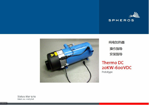
SPHEROS Thermo DC 操作安装手册
汽车与ADR设备 在ADR汽车上,不能预先设定一个开始加热时间,加热器在运 行过程中,液晶屏将显示剩余的加热时间。时钟可以设置,闹 钟功能可以在标准定时器上设置。
3.3 主电路400V电压启动 如果桥接控制线,400V的工作电压下,加热系统将被启动。
查询时间 在车辆点火关闭情况下,按下 按钮。
设置加热器启动时间 按下 按钮, —记忆存储位置将闪烁,这时使用 和 按钮可以设定加 热器开始时间。 —当星期闪烁时,设置星期几。重复按下 存储单元位 置2和3仍可以设置,或跳转到时间显示模式。
查询/删除预设置时间 重复按下 按钮,直到期望的记忆时间显示出来。 删除预设置时间,可以通过按下 多次,直到时间显示,代替已存储 位置。
8
Thermo DC
图5: 加热器安装尺寸 9
1.新鲜空气进风口 2.冷却剂进口 3.冷却剂出口 4 电气组件
Thermo DC
图6:加热器安装位置及开孔
焊接螺钉 M8 - DIN 929
10.8
1. 4 x M8螺钉 2. 4 x M8螺钉 (打穿)
4 x 六角螺母 M8 4 x 垫圈 8.4
高:. 225
kg
15
2
Thermo DC
3、操作
加热系统可通过一个无电势触点(至少30V,1.5A),或通过在 电源400V进行激活。通过无电势触点的激活可以通过开关, 继电器或预选定时器。 控制线越短越好,以保证电压不会降得太多。最长10m,横截 面至少2.5mm²。如果必须使用比较长的电线,那么线路中需 要增加继电器来分散电路功率进而限制长度。
设置闹钟 闹钟时间功能只能在标准定时器上设置。闹钟时间和日设置没 有关联。重复按 按钮,直到闹铃标志 在液晶屏上显示。然后 通过 和 对时间进行调整,设计希望的唤醒时间。铃声5分 钟后关闭或按下任何一个按钮。
OMRON SMARTSTEP A系列 中文说明书

第2章 商品型號、規格
2-3 驅動器規格
g 型號/名稱 : R7D -AP □型/ SMARTSTEP A 系列伺服驅動器
0~+55℃ 90% RH 以下 (不可以結露) 20~+85℃ 90% RH 以下(不可以結露)無腐蝕性氣體。
10~55Hz 複振.1mm 或是加速度4.9 m/s 2以下,其中較低的一方,X 、 Y 、 Z 方向
加速度19.6 m/s 2 以下X 、 Y 、 Z 方向 各3次
電源端子、動力端子與FG 之間 0.5M Ω 以上 (DC500V 電阻)
控制盤內置型(IP10)
項
目
請配合目前使用的馬達,選擇伺服驅動器。
※1. 上述項目是單獨評估試驗的結果。
複合條件下的結果不在此限。
※2. 驅動器嚴禁實施耐電壓試驗、電阻測試,否則內部元件可能受損。
※3. 驅動器的組件中,有部份組件必須因其使用條件而善加維修。
詳細內容請參閱「4-5 定期維護」。
※4. 在平均環境溫度40℃之下,驅動器的使用壽命為5萬小時(額定轉矩的80%輸出)。
2-3-1 一般規格
規
格
保存環境的溫度、濕度使用、保存環境耐振性耐撞擊 絕緣電阻 耐電壓 保護構造
使用環境的溫度、濕度電源端子、動力端子與FG 之間 AC1500V 50∕60Hz 1分鐘 各控制訊號與FG 之間 AC500V 1分鐘。
Abacus100完全使用手册

Abacus100使用手册此使用手册根据阿巴卡斯的使用手册意译过来,能保证绝大部分的准确。
其它很多功能待日后使用到后再添加进来翻译与编辑:黄龙舟******************.cn目录简要配置步骤:_________________________________________________________ 3详细配置步骤___________________________________________________________ 3其它配置______________________________________________________________ 18时间设置(P397)______________________________________________________ 22路径确认(P1193) _____________________________________________________ 24介绍(Introduction)______________________________________________________ 24基本操作(Basic Operation)________________________________________________ 24单个路径确认(Single Path Confirmation) ____________________________________ 25持续或计时的路径确认(Continuous or Timed Path Confirmation)_______________ 25常见错误说明__________________________________________________________ 26 No path confirmation(first)(P1405)_____________________________________ 26No Path Confirmation (Subsequent)(P1409) ________________________________ 27简要配置步骤:1、协议选择:可以配置电路类型,通道类型,协议类型等2、电话号码:配置电话号码和呼叫路由等3、通道和路径确认:配置路径确认类型,音调等级,交换机和结束端变量等4、间隔与时间:配置每组的呼叫脚本和呼叫计时参数等。
SOLAAR032软件手册
UNICAM原子吸收光谱仪SOLAAR32 UNICAM 原子吸收 SOLLAAR32 软件常规手册目录1.引言1.1视窗Windows 951.2视窗Windows 95 帮助文件1.2.1显示视窗Windows 95 帮助信息2.SOLLAAR32程序的安装2.1软件的保护2.2原子光谱仪所用的软件2.3 GFTV(石罴炉进样监控系统)软件2.4软件的安装2.4.1SOLLAR32 数据库软件2.4.2安装升级的SOLAAR32 AutoQC(自动质量控制)软件2.4.3安装GFTV软件和接口组件2.5 SOLLAR 原子吸收组2.5.1阅读Read Me 信息(系统程序的介绍)2.6SOLLAAR32程序的删除2.7SOLLAAR32程序及打印机2.8SOLLAAR32应用程序的启动2.8.1SOLLAAR32的启动2.8.2为SOLLAAR32建立启动菜单快捷键2.8.3为SOLLAAR32建立桌面快捷键2.8.4用视窗Windows 95自动启动SOLLAAR322.9连接SOLAAR32程序3.SOLAAR32软件3.1概述3.1.1方法3.1.2步骤3.1.3样品的说明3.1.4结果3.1.5软件的安全保密性3.2 SOLAAR32的使用3.2.1 SOLAAR32状态窗口3.2.2 SOLAAR32特性页面3.2.3 SOLAAR32对话框3.2.4 SOLAAR32菜单1UNICAM原子吸收光谱仪SOLAAR322 3.2.5 SOLAAR32工具栏3.3.5 SOLAAR32状态栏3.3在线帮助3.3.1 主题3.3.2 学会使用在线帮助系统3.3.3 显示SOLAAR32帮助主题:对话内容表3.3.4 为对话框或特性页快速显示特定文本帮助3.3.5 为状态窗口快速显示特定文本帮助3.3.6为数据输入字段快速显示特定文本帮助4.开始4.1一次简单的火焰分析过程4.1.1开始前的工作4.1.2建立方法4.1.3设定分析顺序4.1.4建立分析样品的详细资料4.1.5安装空心阴极灯4.1.6校准空心阴极灯4.1.7点火,调整燃烧头和雾化器撞击球位置4.1.8进行分析4.1.9审查结果4.1.10打印结果4.2一次简单的石墨炉分析过程4.2.1开始前的工作4.2.2建立方法4.2.3设定分析顺序和样品的详细资料4.2.4安装和校准空心阴极灯4.2.5安装和校准空石墨炉4.2.6调整石墨炉自动进样器4.2.7点火,调整燃烧头位置和雾化器撞击球4.2.8进行分析4.2.9审查并打印结果4.3一次简单的气体分析过程4.3.1开始前的工作4.3.2建立方法4.3.3设定分析顺序和样品的详细资料4.3.4安装和校准空心阴极灯UNICAM原子吸收光谱仪SOLAAR323 4.3.5安装SOLAAR VP90 连续气体流动系统4.3.6安装SOLAAR EC90 电热原子吸收池附件4.3.7准直SOLAAR VP90 原子吸收池4.3.8准直SOLAAR VP90 载气流量,稳定化时间及基线延迟参数4.3.9点火4.3.10没定SOLAAR EC90 石墨炉温度参数4.3.11进行分析4.3.12审查并打印结果5.用户测试软件5.1概述5.2用户检测5.2.1光度计/数据站之间通讯的检测5.2.2光度计/自动进样器之间通讯的检测5.2.3光度计/石墨炉之间通讯的检测5.2.4气体箱泄漏的检测5.2.5光度计模拟电路的检测5.2.6光度计软件版本号的检测5.2.7光度计设置的检测5.2.8新氘(D2)灯5.2.9读数传感器的检测5.3 SOLAAR32 客户检测软件的使用5.3.1客户检测菜单5.3.2客户检测工具条5.3.3操作指导信息窗口5.3.4检测窗口5.3.5在开始之前5.3.6启动客户检测软件5.3.7进行测试5.3.8测试结果6 本系列仪器的异同1 引言祝贺您购卖Unicam SOLAAR 原子吸收光谱仪和SOLAAR32软件.我们竭尽全力为您提供一台功能强大,易于使用的光谱仪. 满足您进行元素分析的所有需求,我们衷心希望您对您的仪器操作及尽快地熟悉起来.UNICAM原子吸收光谱仪SOLAAR32此手册要为您提供SOLAAR32数据工作站软件的安装,使用的指导.本软件应与仪器所配的SOLAAR 用户手册一起使用,特别是:. 硬件手册 - 该手册叙述了光谱仪及其附件的使用和各项功能.. 分析方法手册- 该手册叙述了原子吸收光谱技术的物理和化学原理.同时就样品制备和相关的课题给予实际的指导.. SOLAAR32 在线帮助系统 - 此系统为该软件提供了详细使用说明,而且还包括在线“菜谱”,并给出了所有可用原子吸收光谱测定元素的基本参数.这将在下面的3.3节中进行详细的说明.对SOLAAR969系统也可用Local Controller 而不是Data Station进行设定. Local Controller 软件的使用将在该光谱仪操作手册中予以说明,在此不予讨论.1.1视窗Windows95您的SOLAAR32数据处理工作站软件是在Windows95系统下工作的.该软件是具有强大图形功能新一代帮助操作的系统,它的设计最大限度发挥现代微处理器功能和速度.它可在工作中为您提供许多有用和方便在使用solaar32应用程序之前,你应熟悉和会使用计算机及操作系统。
阿吉斯2.0常规消防报警-灭火控制单元(K-84-200) 说明书
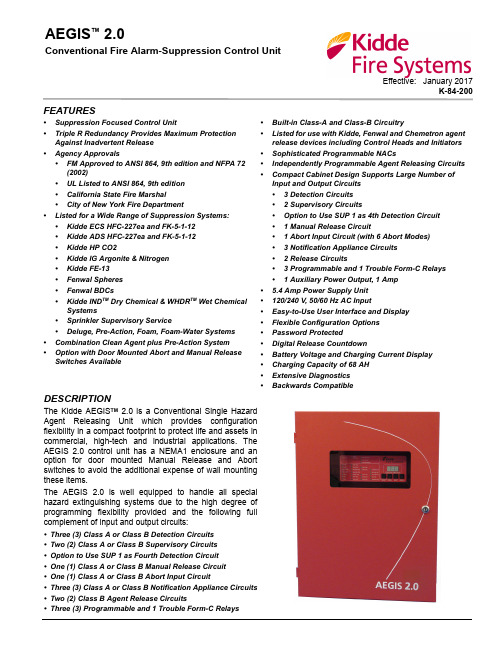
Effective: January 2017K-84-200AEGIS ™ 2.0Conventional Fire Alarm-Suppression Control UnitFEATURES•Suppression Focused Control Unit•Triple R Redundancy Provides Maximum Protection Against Inadvertent Release •Agency Approvals•FM Approved to ANSI 864, 9th edition and NFPA 72(2002)•UL Listed to ANSI 864, 9th edition •California State Fire Marshal•City of New York Fire Department•Listed for a Wide Range of Suppression Systems:•Kidde ECS HFC-227ea and FK-5-1-12 •Kidde ADS HFC-227ea and FK-5-1-12 •Kidde HP CO2•Kidde IG Argonite & Nitrogen •Kidde FE-13•Fenwal Spheres •Fenwal BDCs•Kidde IND TM Dry Chemical & WHDR TM Wet ChemicalSystems•Sprinkler Supervisory Service•Deluge, Pre-Action, Foam, Foam-Water Systems •Combination Clean Agent plus Pre-Action System •Option with Door Mounted Abort and Manual Release Switches Available•Built-in Class-A and Class-B Circuitry•Listed for use with Kidde, Fenwal and Chemetron agent release devices including Control Heads and Initiators •Sophisticated Programmable NACs•Independently Programmable Agent Releasing Circuits •Compact Cabinet Design Supports Large Number of Input and Output Circuits • 3 Detection Circuits • 2 Supervisory Circuits•Option to Use SUP 1 as 4th Detection Circuit • 1 Manual Release Circuit• 1 Abort Input Circuit (with 6 Abort Modes)• 3 Notification Appliance Circuits • 2 Release Circuits• 3 Programmable and 1 Trouble Form-C Relays • 1 Auxiliary Power Output, 1 Amp • 5.4 Amp Power Supply Unit •120/240 V, 50/60 Hz AC Input•Easy-to-Use User Interface and Display •Flexible Configuration Options •Password Protected•Digital Release Countdown•Battery Voltage and Charging Current Display •Charging Capacity of 68 AH •Extensive Diagnostics •Backwards CompatibleDESCRIPTIONThe Kidde AEGIS TM 2.0 is a Conventional Single Hazard Agent Releasing Unit which provides configuration flexibility in a compact footprint to protect life and assets in commercial, high-tech and industrial applications. The AEGIS 2.0 control unit has a NEMA1 enclosure and an option for door mounted Manual Release and Abort switches to avoid the additional expense of wall mounting these items.The AEGIS 2.0 is well equipped to handle all special hazard extinguishing systems due to the high degree of programming flexibility provided and the following full complement of input and output circuits:•Three (3) Class A or Class B Detection Circuits •Two (2) Class A or Class B Supervisory Circuits •Option to Use SUP 1 as Fourth Detection Circuit •One (1) Class A or Class B Manual Release Circuit •One (1) Class A or Class B Abort Input Circuit•Three (3) Class A or Class B Notification Appliance Circuits •Two (2) Class B Agent Release Circuits•Three (3) Programmable and 1 Trouble Form-C Relays- 2 -DETECTION CIRCUITSThe Detection Circuits support Conventional 700 Series,CPD-705x Ionization Smoke, PSD-715x Photoelectric Smoke and THD-705x Heat Detectors as well as Normally Open contact closure type devices. Two circuits are dedicated to the main suppression function and can be programmed to activate the release circuits by either single-shot or cross-zone input. The user configuration allows automatic release via detection to be delayed from 0 to 60 seconds in 10-second intervals and also allows a choice of which of the two Agent Release Circuits to activate.The third Detection Circuit is programmable for either Waterflow or as an independent Detection circuit. When programmed for Waterflow, Notification Appliance Circuits can be programmed as Non-Silenceable as required by certain jurisdictions. Additionally, the Supervisory 1 circuit can be configured to be the fourth detection circuit.SUPERVISORY CIRCUITSThe Supervisory Circuits accept Normally Open contact closure type devices such as pressure switches on the agent cylinders or on the water or air pipe network. The system configuration enables the supervisory input to be a participant in the suppression function. For example,low air supervisory can be included with detection for release of pre-action systems as required by certain jurisdictions.MANUAL RELEASE AND ABORT CIRCUITSBoth the Manual Release and Abort Circuits accept Normally Open contact closure type devices. Activation of the Agent Release Circuits can either be instantaneous or delayed up to 30 seconds (maximum)upon receipt of Manual Release input. Agent release can be temporarily delayed by activating the Abort Circuit.The Abort input can be programmed for 6 modes of operation. These include the UL 10-second mode, the full-delay mode, the IRI mode, two NYC modes, or the abort can be disabled. Aborts can also be programmed to be applicable for either one (ARC 1) or both Agent Release Circuits thereby allowing use with Deluge/Pre-Action systems.NOTIFICATION APPLIANCE CIRCUITS (NAC)The three Notification Appliance Circuits are rated 1.5Amps each and accept polarized 24 VDC Notification Appliances. Each circuit is driven independently and is user configurable for First Alarm, Pre-Release, and Releasing as well as for 60 BPM, 120 BPM, Temporal, or Continuous pattern.The control unit supports appliances that provide the option to use silenceable horns and non-silenceable strobes on the same NAC. Multiple NAC circuits (connected to audible devices only) programmed with the same master code pattern are synchronized, regardless of any differing starting times that preceded their concurrent operation. The NACs configuration includes a user-selectable intelligent synchronization feature which allows a silenceable horn to be shut off while the strobe continues to flash in synchronized fashion.TB1TB2TB3TB4TB5TB6TB7TB8TB9TB10TB11TB12TB17TB16TB15TB14TB19TB18TB13DETECTOR 1DETECTOR 2DETECTOR 3RELEASE ABORT TROUBLE 321BATT OUT AC INRELEASE 1ARC 1RELEASE 2ARC 2AUX 24 VDCNAC 3NAC 2NAC 1AC SUPPLY SELECT SWITCH (S6)DETECTOR 4SUPERVISORY 2Figure 1. Printed Circuit Board (PCB)BUILT-IN CLASS A AND B CIRCUITRYFor the input and NAC circuits, the choice of Class A or Class B supervision is made at site on the board itself by selecting the terminals used for wiring. Neither conversion boards nor additional hardware nor jumper selection is required for this purpose.AGENT RELEASING CIRCUITS (ARC)The two circuits can be programmed for activation by different inputs, with independent time delays and abort modes to fire combinations of two of the following releasing devices:• 1 or 2 Kidde Continuous and Momentary Solenoid Control Heads• 1 Kidde Actuator or Fenwal Initiator• 1 Factory Mutual Group A, B, D, E, F, G, I, J, or K SolenoidIn other words, operating in tandem, the two circuits can release:• 1 or 2 Control Heads on ARC 1 and 1 or 2 Control Heads on ARC 2• 1 or 2 Control Heads on ARC 1 and 1 Actuator/ Initiator on ARC 2 or vice-versa• 1 or 2 Control Heads on ARC 1 and 1 FM Sprinkler Solenoid on ARC 2 or vice-versa• 1 Actuator/Initiator on ARC 1 and 1 Actuator/Initiator on ARC 2• 1 FM Solenoid on ARC 1 and 1 FM Solenoid on ARC 2This configurability is useful for those jurisdictions where the gaseous suppression agent is required to be supplemented with a pre-action system.TRIPLE-R PROTECTION FOR ARCSThe two ARCs feature a triple failure redundancy safeguard system to protect them from inadvertent activation by the main microprocessor. The Triple-R system requires that in order to activate an ARC, the main microprocessor issues two release commands of opposing polarity via separate channels and that these commands be combined with a third signal from the panel watchdog timer to confirm the microprocessor operation. The Triple-R system ensures that electrical transients or disturbances such as power surges that could interfere with the operation of the main microprocessor will not inadvertently activate the connected suppression system. The result is a more robust and reliable suppression-focused panel.PROGRAMMABLE RELAYSOf the 4 relays, three are user-programmable for a variety of alarm related conditions and the fourth is a dedicated trouble relay. All relay contacts are rated 3.0 Amps at 30 VDC/120 VAC (resistive).POWER-LIMITED CIRCUITRYAll circuits are inherently power-limited. ARCs can be configured for power-limited or non-power-limited operation. One in-line releasing device is required for each solenoid on a power limited ARC. In-line releasing devices are not included with the panel; the appropriate number of in-line releasing devices should be ordered using part number 06-220023-001.ROBUST POWER SUPPLY UNIT (PSU)The AEGIS 2.0 features a universal 120/240 V, 50/60 Hz AC Power Supply Unit with a robust 5.4 Amps of 24 VDC power. Input voltage selection is via a slider switch with no jumper cutting required. The on-board battery charger is able to charge 24 VDC (2 x 12) batteries of capacity up to 68 AH thereby allowing from 24 hours of supervision plus 5 minutes of alarm to 90 hours of supervision plus 10 minutes of alarm required by some jurisdictions. AUXILIARY POWER SUPPLYUp to 1 Amp of auxiliary power at 24 VDC is available to power external 4-wire devices such as Flame Detectors, AlarmLine modules, Duct Detectors, etc. The auxiliary power output is resettable.ELEGANT USER INTERFACEThe user interface consists of an array of LED Indicators, Control Switches, a Digital Display, and Buzzer. Over and above the System, Power Supply status, Input circuit Fire and Trouble and Output circuit Trouble LEDs, the AEGIS 2.0 annunciates its suppression state-of-alarm via three additional Pre-Release, Releasing and Post Release LEDs. Four switches are provided, one each for Acknowledge, Signal Silence, System Reset and Output Disable. The 3-digit display provides a countdown of impending agent release. On command from the user interface switches, it also indicates the battery open circuit voltage and charging current.SIMPLE SITE-SPECIFIC CONFIGURATIONSetting the site-specific configuration is easily done using the digital display and user interface buttons. To prevent unauthorized use, the configuration menu is protected by a user-changeable password. Factory technical support can provide assistance with lost or forgotten passwords. Apart from the input voltage selection performed on both the PSU and main board via a slider switch, no other on-board settings or jumper cuttings are required. EXTENSIVE DIAGNOSTICSAlso initiated via the digital display and user interface switches, the troubleshooting function displays diagnostic codes that assist in determining causes of trouble. A complete list of diagnostic codes and their meaning ships factory installed on the inside of the enclosure door for easy reference.- 3 -BACKWARDS COMPATIBILITYThe AEGIS 2.0 is backwards compatible and listed for use with a full range of conventional detectors and alarm devices as well as suppression accessories from Kidde, Fenwal and Chemetron. Going forward, this will allow legacy panels to be replaced with relative ease.EASY TO INSTALL CABINETThe cabinet design allows for easy installation by fitting between the studs of a standard 16 inch studded wall. It is large enough to house two 12 VDC, 12 AH Batteries and provides up to 2 inches (51 mm) of wiring and finger space between the circuit board and the cabinet wall. An optional door design features a Manual Release and Abort switch for applications with space constraints. Both switches incorporate guards that prevent their inadvertent activation.TECHNICAL SPECIFICATIONS•Hazards Protected- One•Power Supply- 120/240 V, 50/60 Hz (90 to 264 Vrms, 47 to 63 Hz)AC Main Input- 5.4 Amps at 27 VDC Output- Battery capacity up to 68 AH @ 24 VDC- Auxiliary power output rated at 1 Amp at 18.8 - 27.6VDC (resettable)•Three (3) or Four (4) Detection Circuits- Compatible with 700 Series, CPD-705x, PSD-715x,and THD-705x detectors as well as Normally Opencontact closure type devices. Refer to documentsK-70-100 and F-70-63 for details on compatibilityand the maximum number of devices supported.- Configurable as Class A/Style D or Class B/Style B - Supervised for ground faults and open circuits- Power limited- DET 1 and DET 2 used for suppression- DET3/WF configurable for detection or waterflow- Option to use SUP 1 circuit as DET 4 circuit •One (1) Manual Release Circuit- Compatible with normally open contact-closure typedevices- Configurable as Class A/Style D or Class B/Style B - Supervised for ground faults and open circuits- Power limited TECHNICAL SPECIFICATIONS (cont’d)•One (1) Abort Circuit- Compatible with normally open contact-closure type devices- Configurable as Class A/Style D or Class B/Style B - Supervised for ground faults and open circuits- Six (6) Abort Modes available- Power-limited•Two (2) Supervisory Circuits- Compatible with normally open contact-closure type devices- Configurable as Class A/Style D or Class B/Style B - Option to use SUP 1 as 4th detection circuit- Supervised for ground faults and open circuits- Power-limited•Three (3) Notification Appliance Circuits (NACs) - Compatible with polarized 24 VDC Audio-Visualdevices- Rated at 1.5 Amps each- Up to 35 synchronized appliances- Configurable as Class A/Style Z or Class B/Style Y - Supervised for ground faults, shorts, and opencircuits- Power-limited- Common NAC/ARC output disconnect switch •Two (2) Agent Release Circuits- Each compatible with 1 or 2 control heads, or 1actuator/initiator, or 1 FM sprinkler solenoid- Circuits electrically capable of simultaneouslyreleasing any combination of two of the abovedevices- Factory configured as Class B/Style Y- Supervised for ground faults and open circuits- Default setting: Power-Limited. Each solenoid on apower-limited ARC requires the use of an in-linereleasing device, P/N 06-220023-001 (orderseparately, not included with panel).- Common NAC/ARC output disconnect switch •Four (4) Relays- 3 independently programmable, normally de-energized Form-C Relays- 1 dedicated normally energized Form-C TroubleRelay- Relay contacts rated 3 Amps at 30 VDC/120 VAC(resistive)- 4 -- 5 -TECHNICAL SPECIFICATIONS (cont’d)•Enclosure- NEMA 1 rated 18 gauge sheet steel with door - Red color- Suitable for wall and surface mounting - Optional Trim Ring- Optional door with Manual Release and Abort switches-Optional Dead Front Plate - Dimensions:- with Standard Door:14-1/4 in. W x 5 in. D x 19 in. H (362 mm x 127 mm x 483 mm) - with Switch Door:14-1/4 in. W x 6 in. D x 19 in. H (362 mm x 152 mm x 483 mm)•Environmental Criteria- Indoor/Dry use only- Operating temperature range: 32°F to 120°F (0°C to 49°C)- Humidity: 93 ± 2% RH at 90 ± 3°F (32 ± 2°C)•Packaging/Shipping- Enclosure, PCB, and PSU packaged in individual cartons. Field assembly is required.- Accessories shipped include mounting hardware, battery leads, IOM manual on CD-ROM, operating instruction sheet, and EOL resistor kit.- Order in-line releasing device (required for power-limited ARCs) and batteries separately.ORDERING INFORMATIONDescriptionPart Number Kidde AEGIS 2.0 Control Unit 84-732001-901Kidde AEGIS 2.0 Control Unit with Switches84-732001-902In-Line Releasing Device 06-220023-001Dead Front Plate 06-220175-001EOL Resistors (10 pk)06-220184-001Trim Ring76-600000-007Large Capacity Battery Enclosure 76-100010-001Installation/Configuration Kit06-220148-902Replacement Hardware Installation Kit 06-220149-001Replacement Enclosure Assembly 06-220172-902Replacement Enclosure Assembly (with Switches)06-220174-902Replacement Door Switches Kit 06-220176-001Replacement PCB Assembly 06-220150-901Replacement Power Supply 06-118394-002Replacement Bezel Assembly 06-220151-001Spare Key06-118013-001Spare Keylock with Keys06-129924-001400 Main StreetAshland, MA 01721 USA Tel: 508.881.2000This literature is provided for informational purposes only. KIDDE-FENWAL, INC. believes this data to be accurate, but it is published and presented without any guarantee or warranty whatsoever. KIDDE-FENWAL, INC. assumes no responsibility for the product's suitability for a particular application. The product must be properly applied to work correctly. If you need more information on this product, or if you have a particular problem or question, contact KIDDE-FENWAL, INC., Ashland, MA 01721 USA. Telephone: (508) 881-2000.K-84-200 Rev AC © 2017 Kidde-Fenwal Inc.AEGIS is a trademark of Kidde-Fenwal, Inc.All other trademarks are the properties of their respective owners.For detailed installation, operation, and configuration information, refer to the Kidde AEGIS 2.0 Conventional Fire Alarm-Suppression Control Unit Installation, Operation, and Maintenance Manual P/N 06-237463-001.EXPORT INFORMATION (USA): Jurisdiction: EAR, US ECCN: EAR99 This document contains technical data subject to the EAR.。
阿基斯莫电子产品介绍说明书

4-1462039-2Axicom IM, Signal Relays, 250VAC Contact Voltage Rating, 220VDC Contact Voltage Rating, 100mW Signal Relay Coil Power Rating (DC)Relays, Contactors & Switches > Relays >Signal RelaysInsertion Loss (HF Parameter):-.03dB @ 100MHz, -.33dB @ 900MHzIsolation (HF Parameter):-18.8dB @ 900MHz, -37dB @ 100MHzSignal Relay Coil Power Rating (DC):100 mWContact Voltage Rating:220 VDCFeaturesProduct Type Features Relay Type IM Relay Product TypeRelayElectrical Characteristics Coil Power Rating Class 50 – 300 mW Actuating SystemDC Insulation Initial Dielectric Between Open Contacts 1000 Vrms Contact Limiting Short-Time Current2 A Insulation Initial Dielectric Between Contacts and Coil 1800 Vrms Insulation Initial Dielectric Between Coil/Contact Class 1500 V – 2500 VAVoltage Standing Wave Ration (HF Parameter) 1.06 @ 100MHz, 1.49 @ 900Mhz Insulation Initial Dielectric Between Adjacent Contacts 1800 Vrms Insulation Initial Resistance 1000000 MΩContact Limiting Making Current 2 A Coil Resistance90 ΩContact Limiting Continuous Current 2 A 4-1462039-2 ACTIVEAxicom TE Internal #:4-1462039-2Axicom IM, Signal Relays, 250VAC Contact Voltage Rating, 220VDC Contact Voltage Rating, 100mW Signal Relay Coil Power Rating (DC)View on >Axicom IM|Coil Type BistableContact Limiting Breaking Current 2 AContact Switching Load (Min).1mA @ .0001VContact Voltage Rating220 VDCSignal Relay Coil Power Rating (DC)100 mWSignal Relay Coil Voltage Rating 3 VDCSignal Relay Contact Switching Voltage (Max)220 VDCSignal Relay Coil Magnetic System Bistable, 1 CoilSignal CharacteristicsIsolation (HF Parameter)-18.8dB @ 900MHz, -37dB @ 100MHz Insertion Loss (HF Parameter)-.03dB @ 100MHz, -.33dB @ 900MHz Body FeaturesInsulation Special Features2500V Initial Surge Withstand Voltagebetween Contacts & CoilWeight.75 g[.026 oz]Contact FeaturesContact Plating Material GoldContact Current Class0 – 2 AContact Special Features Bifurcated/Twin ContactsSignal Relay Terminal Type PCB-SMTSignal Relay Contact Current Rating 2 ASignal Relay Contact Arrangement 2 Form C (2 CO)Contact Material PdRu+AuContact Number of Poles2Termination FeaturesTermination Type Surface MountMechanical AttachmentSignal Relay Mounting Type Printed Circuit BoardDimensionsWidth Class (Mechanical)0 – 6 mmWidth 6 mm[.236 in]Height 5.65 mm[.222 in]Length Class (Mechanical)0 – 10 mmLength10 mm[.393 in]Height Class (Mechanical)0 – 6 mmDimensions (L x W x H) (Approximate)10 x 6 x 5.65 mm[.393 x .236 x .222 in] Usage ConditionsEnvironmental Ambient Temperature (Max)85 °C[185 °F]Environmental Ambient Temperature Class70 – 85°CEnvironmental Category of Protection RTVOperating Temperature Range-40 – 85 °C, -40 – 85 °COperation/ApplicationPerformance Type High DielectricPackaging FeaturesPackaging Method ReelOtherAdditional Features Gull WingProduct ComplianceFor compliance documentation, visit the product page on >EU RoHS Directive 2011/65/EU CompliantEU ELV Directive 2000/53/EC CompliantChina RoHS 2 Directive MIIT Order No 32, 2016No Restricted Materials Above ThresholdEU REACH Regulation (EC) No. 1907/2006Current ECHA Candidate List: JUN 2020(209)Candidate List Declared Against: JUL 2019(201)Does not contain REACH SVHCHalogen Content Low Bromine/Chlorine - Br and Cl < 900ppm per homogenous material. Also BFR/CFR/PVC FreeSolder Process Capability Reflow solder capable to 260°CProduct Compliance DisclaimerThis information is provided based on reasonable inquiry of our suppliers and represents our current actual knowledgebased on the information they provided. This information is subject to change. The part numbers that TE has identified asEU RoHS compliant have a maximum concentration of 0.1% by weight in homogenous materials for lead, hexavalentchromium, mercury, PBB, PBDE, DBP, BBP, DEHP, DIBP, and 0.01% for cadmium, or qualify for an exemption to theselimits as defined in the Annexes of Directive 2011/65/EU (RoHS2). Finished electrical and electronic equipment productswill be CE marked as required by Directive 2011/65/EU. Components may not be CE marked. Additionally, the partnumbers that TE has identified as EU ELV compliant have a maximum concentration of 0.1% by weight in homogenous materials for lead, hexavalent chromium, and mercury, and 0.01% for cadmium, or qualify for an exemption to these limits as defined in the Annexes of Directive 2000/53/EC (ELV). Regarding the REACH Regulation, the information TE provides on SVHC in articles for this part number is based on the latest European Chemicals Agency (ECHA) ‘Guidance on requirements for substances in articles’ posted at this URL: https://echa.europa.eu/guidance-documents/guidance-on-reachTE Model / Part #YDTS20Z15-19SAV001RECP ASSYTE Model / Part #1-825433-1MOD 2 PINHDR 1X11P.TE Model / Part #160088-1RING TONGUE 20-16 AWG 0.198 X .700 BRTE Model / Part #1-1415537-7RTD1L005TE Model / Part #1586963-104P UMNL PIN HDR ASSY, GWTE Model / Part #10213286-00DIGITAL THERMOPILE SENSORTE Model / Part #1-1546927-212P .325 TRI-BARRIER W/COVERTE Model / Part #1-1415017-1SR6C4012 - V23050-A1012-A551Signal Relays(122)RJ45 Connectors(2) TE Model / Part #6-1462039-8IM41DGR=IM RELAY 100 MW 3 V BisTE Model / Part #CAT-AX41-IM11B IM STANDARD (2 FORM C, 2CO CONTACTS)Compatible PartsAlso in the Series Axicom IMCustomers Also BoughtTE Model / Part #YDTS20Z25-35PNV001RECP ASSYTE Model / Part #YDTS20Z21-35PNV001RECP ASSYDocumentsProduct DrawingsIM41CGR=IM-RELAY 100MW 3V BISEnglishIM41CGR=IM-RELAY 100MW 3V BISEnglishDatasheets & Catalog PagesAxicom Signal and High Frequency Relays (RF Switches) APPLICATION NOTE #2EnglishIM Relay DatasheetEnglishIndustrial Relays Quick Reference GuideEnglishProduct SpecificationsDefinitions RelaysEnglish。
200SA说明书翻译

一重要信息这些说明写给操作GOW-MAC系列200SA硫分析仪的个人。
请阅读并理解手册里的安全提示,操作仪器时能熟悉安全操作。
DANGER:提醒你一个可能随时(即刻)发生的的危险将引起严重的伤害或死亡并且需要特别的警惕。
W ARNINGS:提醒你一个潜在的危险将在一定条件下引起也能中的伤害或死亡。
CAUTIONS:提醒你一个非立刻的或潜在的危险或一个不安全的操作,代表一个对身体伤害或损伤的一个小威胁。
NOTE:强调或提醒你一个重要的信息。
内容质量控制最终仪器监测报告重要警告、通知总的通知和安全总的操作前提示和储存高压钢瓶的提示1.操作原理1.1检测器1.2流量系统1.3电子元件2.规格3.操作控制3.1 200SA系列前面板。
3.2 200SA系列后面板4.安装4.1仪器需求4.2拆包装并留意检查4.3安装定位4.4电器连接4.5气体连接4.6检漏5.初始化程序:气体流量5.1注意FDP器械里的点火操作5.2设置气体流量6.操作6.1启动,开机6.2编程6.3标定6.4运行7.维修和服务7.1更换炉备件7.2反应炉烘烤7.3FPD更换、清洁8.疑难解决9.更换部件10.图质量控制监测报告仪器型号仪器序列号后面省略炉温检测器温度毫伏输出载气流速出口2流速(反冲)FPD总燃气氢气流速FPD总空气流速NIST可追溯的标准相关号二氧化碳中0.5-1.5ppm的羰基硫仪器显示读数电流限值20mA(1ppm)真实4mA (0ppm)真实激发准备日期技师重要警告安装、使用或维修这个产品的个人应该仔细阅读这个手册。
像其他的复杂仪器,这个200SA系列的硫分析仪只有在按照供应商说明书来安装使用和维护,这个仪器才会按设计的运行。
否则这个仪器将不能按设计的运行,并且操作这个仪器的人会有严重的身体伤害甚至导致死忙。
这个保证由GOW-MAC仪器公司承诺,避免仪器没有按照手册的说明来安装、使用和维护。
请按照这些操作说明来保护您自己以及您的员工。
DCS操作说明书

本文导语说到DCS的操作,不少化工人都关心应该从哪儿学起?实际应用中应该注意哪些问题?其实,DCS是现场施工的平面体现,真正要学还是应从现场学起,然后和DCS 的操作界面对应起来。
首先要有扎实的理论基础知识,然后才能结合DCS的操作方案来很好地调整或控制现场。
比如:理解反应时,针对不同的反应,理解温度、压力、流量、组分含量、分布等对反应的影响,多个控制手段,分清主次,弄清各个参数对反应影响的大小,如何调到最优等。
经验人士说,熟读DCS操作手册是第一步,因为这些是经验总结,而后根据实际操作慢慢理解消化。
小7接着上次DCS的介绍,今天来说DCS系统的操作方法。
本文列举的是河南某化工公司离子膜烧碱项目的DCS操作说明。
一、总体说明1.系统软件本规程所涉及的操作均在操作站上实现,系统软件由ADVANTROLPRO 2.50和组态文件构成。
系统的所有操作均在Advantrol软件下实现。
2.本规程提及的术语1)注意:表示涉及的事物或操作可能引起不可预测的危险后果。
2)警告:表示涉及的事物或操作能引起可预见的系统运行故障。
3)危险:表示涉及的事物或操作将引起系统停运,甚至设备损坏及人身伤害。
3.操作员操作职责1)监视DCS系统运行,预防可能产生的危险。
2)随时干预系统运行,确保安全、正常生产。
3)系统授权运行参数的更改。
4.系统异常情况处理1)DCS操作界面数据不刷新(正常情况数据每秒刷新一次),手自动切换无法操作等情况,应联系DCS 维护人员进行维护,同时立即到现场操作。
2)出现变送器故障,自动控制过程应立即切回手动。
3)出现阀门执行机构,回路输出卡件等故障现象,应改为现场操作。
4)出现DCS系统回路输入卡件故障时应把相应控制回路切回手动,并更换故障卡件,检查确认故障消除后方可再次投入自动。
5)DCS系统出现异常断电,应改为现场操作。
重新上电后,要求工程师检查系统情况,检查回路参数等系统数据是否正常,确认各调节阀的开度。
DCS系统操作说明书

EPS干法无尘2100纸机DCS系统操作说明书绵阳海天斯威福特有限责任公司2019年10月22日DCS 系统操作说明书开机,进入WINXP 操作系统后,就会显示登陆画面。
按“CTRL ”、“L ”组合键,弹出系统登陆框,此时输入用户名和密码,然后就可以进入到操作界面。
界面上方是界面下方是“备料系统”按钮是工艺流程中关于绒毛浆分解、SAP 和ES 配比、喷胶画面等等的切换按钮,当操作员点击按钮后,按钮颜色就从灰色变为绿色,并且显示该画面;“成型部”按钮是用来切换干法无尘纸机中成型工段的相应画面; “传递部”按钮是用来切换干法无尘纸机中传递工段的相应画面; “上喷胶部”按钮是用来切换干法无尘纸机中上喷胶工段的相应画面; “预热部”按钮是用来切换干法无尘纸机中预热工段的相应画面; “下喷胶部”按钮是用来切换干法无尘纸机中下喷胶工段的相应画面;“固化部”按钮是用来切换干法无尘纸机中固化工段的相应画面;“熟化部”按钮是用来切换干法无尘纸机中熟化工段的相应画面;“压光冷却部”按钮是用来切换干法无尘纸机中压光冷却工段的相应画面;“配胶部”按钮是工艺流程中的配胶计量输送画面的切换按钮;“其他”按钮是工艺流程中的AC系统、锅炉供水、现场急停显示、声光报警种类、其他剩余部分的画面;“除尘部”按钮是工艺流程中专门针对过滤空气中尘埃的画面。
里面显示登陆的当前用户名称,如果是空白,就表明当前系统并没有用户登陆,不能操作任何按钮;项目编号是系统的出厂号,便于项目的跟踪管理;“退出系统”是关闭WINCC项目,而不退出操作系统,只有管理员才有权限操作。
操作员如果点击,就会出现权限不够的提示:管理员有权使用:“关闭系统”是不仅要关闭WINCC项目,而且要退出操作系统,彻底关闭电脑。
显示当前的日期和时间。
按钮是用来打印当前全屏幕画面的。
功能就是便于操作员纪录当前的水分横幅分布和雾化喷头的调节情况。
操作员选择“是”,就将画面输出到网络打印机。
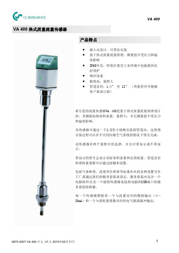
IM_0007_VA400_CHINESE_V1.1_使用手册
注意: 1. 在开启球阀的时候,用另外一只手按住流 量计。 2. 缓慢打开流量计。
0970 0007 VA 400 中文, V1.1, 2010年02月11日
7
VA 400
5. 将流量传感器插入管道中心
OD = 外径 刻度
x
dA 2
插入深度 = x + y 锁紧帽 在这里读取“插入深度”! 球阀顶部
安装考虑事项
为了保持数据表中所指明的精度,传感器必须被插入气体流动不受阻碍的一段直管的中央。 要使得气体流动不受阻碍,传感器前面(上游段)以及传感器后面(下游段)的管道必须足够 长,绝对笔直,并且不存在边缘、接缝、弯道等障碍物。 必须十分注意下游段的设计,因为任何障碍物都可造成逆向或正向的涡流。 本传感器只能安装在室内使用!假如要安装在室外,必须避免太阳直晒和雨水冲洗。 注意: 我们强烈建议不要将VA 400永久地安装在潮湿环境中。这种潮湿环境通常存在于压缩机输出之 后。其会导致错误的测量结果和传感器的老化,因此只应进行临时安装。
测量范围 从…到 3.5 ... 1500 l/min 0.4 ... 170 m³/h 0.6 ... 290 m³/h 1.2 ... 530 m³/h 1.5 ... 720 m³/h 2.5 ... 1190 m³/h 5 ... 2180 m³/h 7 ... 3130 m³/h 12 ... 5270 m³/h 18 ... 7800 m³/h 25 ... 11090 m³/h 33 ... 17530 m³/h 52 ... 27420 m³/h 80 ... 39540 m³/h
注意: 请确保实际的气体流向和 这里箭头所示的相同。 8. 最后检查 检查插入深度。有时候由于气体压力较大,测量杆可能会被推出来一些。针对这种情 况,安装人员需要微调插入深度并将锁紧帽再拧紧一点。最后不要忘记调整方向,因为 拧紧锁紧帽的时候方向可能会有点变化。 9. 连接电缆 警告! 不要用蛮力去拧这个接头!否则接头的引脚将会被折断。 电缆通过一个叫做M12的连接器与传感器相连。 连接步骤:
Aeroflex PSD60-1AF 燃料量测试设备操作手册说明书

OPERATION MANUALPSD60-1AFFUEL QUANTITY SYSTEMS TEST SETMANUAL NUMBER:06-0605-0A (Hard Copy)E6-0605-0A (CD)REVISION:0DATE:05/16/2007WARNING: INFORMATION SUBJECT TO EXPORT CONTROL LAWSThis manual may contain information subject to the International Traffic in Arms Regulation (ITAR) or the Export Administration Regulation (EAR) which may not be exported, released, or disclosed to foreign nationals inside or outside of the United States without first obtaining an export license. A violation of the ITAR or EAR may be subject to a penalty of imprisonment and/or fines under 22 U.S.C.2778 of the Arms Export Control Act or section 2410 of the Export Administration Act. Include this notice with any reproduced portion of this document.This document is proprietary to Aeroflex, and is not to be reproduced or otherwisedisseminated without the written consent of Aeroflex.400 New Century Parkway – New Century, Kansas – 66031Telephone: (800) 237-2831 / (913) 764-2452 Fax: (913) 782-5104ELECTROSTATIC DISCHARGE GENERAL WARNINGS FOR ALL EQUIPMENTCAUTION:THIS EQUIPMENT MAY CONTAIN ELECTROSTATIC DISCHARGE (ESD) SENSITIVE COMPONENTS. TO PREVENT ESD SENSITIVE EQUIPMENT FROM POSSIBLEDAMAGE, OBSERVE THE FOLLOWING PRECAUTIONS WHEN HANDLING ANY ESDSENSITIVE COMPONENTS, OR UNITS CONTAINING ESD SENSITIVECOMPONENTS:a. Maintenance or service personnel must be grounded though a conductive wrist strap, or a similargrounding device, using a 1 MΩ series resistor for equipment protection against static discharge, and personal protection against electrical shock.b. All tools must be grounded (including soldering tools) that may come into contact with theequipment. Hand contact will provide sufficient grounding for tools that are not otherwisegrounded, provided the operator is grounded through an acceptable grounding device such as a wrist strap.c. Maintenance or service of the unit must be done at a grounded, ESD workstation.d. Before maintenance or service of the equipment, disconnect all power sources, signal sources,and loads connected to the unit.e. If maintenance or service must be performed with power applied, take precautions againstaccidental disconnection of equipment components. Specifically, do not remove integratedcircuits or printed circuit boards from equipment while the equipment has power applied.f. All ESD sensitive components are shipped in protective tubes or electrically conductive foam.The components should be stored using the original container/package when not being used or tested. If the original storage material is not available, use similar or equivalent protectivestorage material.g. When ESD sensitive components are removed from a unit, the components must be placed on aconductive surface, or in an electrically conductive container.h. When in storage or not being repaired, all printed circuits boards must be kept in electricallyconductive bags, or other electrically conductive containers.i. Do not unnecessarily pick up, hold, or directly carry ESD sensitive devices.Failure to comply with these precautions may cause permanent damage to ESD sensitive devices. Thisdamage can cause devices to fail immediately, or at a later time without apparent cause.Aeroflex Operation ManualREVISION HISTORYMANUAL: PSD60-1AF Fuel Quantity Systems Test SetREVISION: 0 – May 16, 2007REV. REV. DRAWING NO. LEVEL DRAWING NO. LEVEL Table of Contents 0Section 1 0Section 2 0DRAWING REVISION HISTORY – PSD60-1AF – MAY 16, 2007 -- PAGE 1 OF 1。
Saeco Xelsis 系列咖啡机用户手册说明书

繁體中文 6內容重要防護措施__________________________________________________________________________________________6請保存使用說明________________________________________________________________________________________7警告:_________________________________________________________________________________________________7電源線的指示__________________________________________________________________________________________7重要安全資訊__________________________________________________________________________________________7簡介 ___________________________________________________________________________________________________9咖啡機概觀 (圖 1)______________________________________________________________________________________9首次安裝_______________________________________________________________________________________________10使用控制面板__________________________________________________________________________________________10AquaClean 濾水器_____________________________________________________________________________________11測試水質硬度__________________________________________________________________________________________11沖煮飲品_______________________________________________________________________________________________12客製化飲品,建立個人設定____________________________________________________________________________13調整咖啡機的設定_____________________________________________________________________________________13處理沖煮組件__________________________________________________________________________________________14清潔與維護____________________________________________________________________________________________14除鈣程序_______________________________________________________________________________________________16錯誤碼_________________________________________________________________________________________________17訂購配件_______________________________________________________________________________________________17疑難排解_______________________________________________________________________________________________17飲品類型與份量________________________________________________________________________________________20技術規格_______________________________________________________________________________________________21處理方式_______________________________________________________________________________________________21保固與支援____________________________________________________________________________________________21重要防護措施重要防護措施使用電子產品時,必須隨時遵照基本的安全防護措施進行,包括下列項目:1閱讀所有指示。
DCS中文使用说明3
<前言> <目录> <索引> i 说明书修改信息资料名称: 工程技术测试指南资料号码: IM 33S04N10-012002年12月/8版/R3.03以后** : 说明书记载内容和所对应的软件的版本号码。
所对应的范围到下次修订版发行为止。
A1.1节在CS 1000中根据支持了球形开关的变更(追加CS 1000的球形开关断开/连接功能)A1.1节追加FOUNDATION Fieldbus面板块测试(仅对CS 3000 KFCS2/KFCS)A1.3节追加MC-2E,MC-3E说明A1.3节删除关于FOUNDATION Fieldbus面板块的说明A1.4节在CS 1000中根据支持了球形开关断开/连接功能的变更A3章 为CS 3000 KFCS2/KFCS追加新的IOMA4章 在CS 1000中根据支持了球形开关断开/连接功能,删除CS 1000/CS 3000分列A4章 追加目标测试时的球形开关的操作说明A5.10节新追加「A5.10 扩展型接点输入输出连接功能块的配线」A14章 在CS 1000中根据支持了球形开关断开/连接功能,删除CS 1000/CS 3000分列A15章 根据off side块成为快拍保存/负载的对象而变更A15章 在CS 1000中根据支持了球形开关断开/连接功能,删除CS 1000/CS 3000分列B2.3节 在CS 1000中根据支持了球形开关断开/连接功能,删除CS 1000/CS 3000分列B4.2节在CS 1000中根据支持了球形开关断开/连接功能,删除CS 1000/CS 3000分列C1.4节新追加「C1.4扩展型接点输入输出连接功能块用的配线类型」C2.1.5项新追加「C2.1.5扩展型接点输入输出连接功能块的配线变换」C2.2.4项新追加「C2.2.4扩展型接点输入输出连接功能块用的配线常数」C3.3节追加“■ 配线类型的自动决定-扩展型接点输入输出连接功能块的情况”说明D2.1节变更“不与其他PC的连接”检查栏的说明D2.7节为启动命令接口追加参数“-W”D2.7节新追加停止命令接口2001年12月/7版/R3.02以后A1.2节根据新型FCS(KFCS2,LFCS2)的追加而变更A3章 根据新型FCS(KFCS2,LFCS2)的追加而变更A3章 根据新IOM(AAP149-S)的追加而变更A11.2节根据新型FCS(KFCS2,LFCS2)的追加而变更2001年4月/6版/R3.01以后从“测试功能说明书”变更为“工程技术测试指南”手册名称A1-4 变更表A1-5 追加表A1-6~A1-7 错页A1-6 追加CS 1000/CS 3000分列,变更表,追加表的注释A1-7 追加■标题,变更表的题目,追加表A1-8 追加页,追加表A1-9~A1-13 错页A1-9 追加说明文A1-10 追加说明文A3-2 追加重要事项A3-4 变更图的题目A3-5 变更图的题目A3-6~A3-8 新追加A3-9~A3-11 错页A3-9 误记订正A3-10 误记订正A3-12~A3-13 新追加A5-8 变更表中的组态名称A5-9 把注意事项移动至次页A5-10 追加关于现场总线面板块的注意事项A5-12 删除说明文的一部分A5-13 变更内容提要A5-16 把■标题和说明文移动到次页A5-17~A5-24 错页A5-19 变更内容提要A10-5 变更表A11-2 追加CS 1000/CS 3000分列,变更表A11-3 追加页A11-4~A11-5 错页A12-1 变更本文的一部分A12-4 追加CS 1000/CS 3000分列,为表追加注脚A12-5 变更表A12-8 删除文本的一部分A12-J 变更图A14-1 追加注意事项A15-1 追加注意事项,追加文本,把说明文的一部分移到下一页A15-2 把说明文的一部分从前一页移动A16-3 变更文本中和表中的组态名称B2-7 变更图B2-11 变更图B3-11 变更图B3-12 变更图B3-21 变更图B4-3 变更文本中的组态名称C3-12 变更本文的一部分C3-14 变更表中的组态名称D1-5 删除“■ 扩展测试功能的硬件环境”D1-6~D1-10 错页D1-5 变更■标题题目,变更文本的一部分D1-7 变更本文的一部分D1-J 删除页D2-6 变更本文的一部分D2-11 变更参考目标D2-N 变更本文的一部分D2-15 变更本文的一部分2000年1月/5版/R2.10以后A1-6 追加本文A1-7 变更本文A3-3~A3-4 变更图A3-5 追加图。
DCS中文使用说明2

用户使用手册工程技术测试指南IM 33S04N10-01Y O K O G A W A◆IM 33S04N10-018版前言测试功能是指为了高效率地测试(调试)用户作好的应用软件的工具群。
本书记述了有关测试功能的功能说明、操作说明。
如果使用测试功能,即使没有实际的FCS也可以测试用户制作的应用软件。
取代实际的FCS使用FCS仿真器进行测试行,这叫做虚拟测试。
FCS仿真器是把FCS的功能或动作用软件进行模拟,它包含于测试功能中。
另一方面,用实际的FCS进行的测试被称作目标测试。
本书由4个部分组成,如下所示。
● A部分功能说明篇在A部分,就测试功能所具有的各项功能的详细情况作了说明。
使用测试功能的用户请先读前言。
想了解有关测试功能的各项功能时,请参考本部分。
● B部分操作说明篇在B部分,就测试功能的启动操作、测试功能所具有的各项功能的操作以及测试功能的结束操作进行说明。
想了解有关测试功能的操作时,请参考本部分。
● C部分配线详细篇在测试功能中,对FCS的程序输入输出端子进行假想配线的配线功能。
根据该功能,即使不去为了测试而准备输入输出卡件,也可以测试FCS控制动作。
在C部分,就配线功能中的配线类型、配线变换方式、配线常数以及配线数据的自动制作进行说明。
想详细了解配线类型或配线常数时,请参考本部分。
● D部分扩展测试功能篇扩展测试功能是指为了扩展虚拟测试功能的选购程序包。
如果使用扩展测试功能,则有可能测试使用了复数台PC的FCS仿真器。
在D部分,就基于该复数PC的测试进行说明。
Media No. IM 33S04N10-01 (CD) 8th Edition : Dec. 2002 (YK) IM 33S04N10-01 8th Edition : 2002.12.16-00安全使用所需的注意事项■ 与本产品的保护・安全以及改造有关的注意事项・为了本产品以及在本产品控制的系统的保护・安全,在操作本产品时,请遵守说明书中所记载的有关安全的指导事项。
DCS_MiG-21bis键位表(中英文版V1.2)

"RAlt - RCtrl - B" "RCtrl - B" "RAlt - 1" "RAlt - 2" "RAlt - 3" "RAlt - 4" "RAlt - 5" "RAlt - 6" "RAlt - 7" "RAlt - 8" "RShift - 1" "RShift - 2" "RShift - 3" "RShift - 4" "RShift - 5"
16 ARK channel 6 17 ARK channel 7 18 ARK channel 8 19 ARK channel 9 20 Accelerometer Reset
ARK 频道 6 ARK 频道 7 ARK 频道 8 ARK 频道 9 加速计复位 危险高度设置 100m 危险高度设置 150m 危险高度设置 200m 危险高度设置 250m 危险高度设置 300m 危险高度设置 400m 危险高度设置 50m 危险高度设置 关 紧急皮托管加热 关 紧急皮托管加热 开 ADI姿态指示器电门(包含ILS 以及高度、航向/径向指针) ADI姿态指示器 应急模式 ADI姿态指示器 主要的模式 HIS航向指示器 - ARK 模式
DCS_MiG-21bis键位表(中英文版V1.2)by lkyfly1266.xlsx
DCS_MiG-21bis键位表(中英文版)(by_lkyfly1266)
序号 英文 中文说明 键位
航空电子 Avionics
1 2 3 4 5 6 7 8 9 ARK Off ARK On ARK Sector I-1 Ukraine ARK Sector I-2 free ARK Sector II-1 Russia ARK Sector II-2 Russia ARK Sector III-1 Georgia ARK Sector III-2 free ARK Sector IV-1 free ARK 关 ARK 开 ARK 制式 I-1 乌克兰 ARK 制式 I-2 free ARK 制式 Iቤተ መጻሕፍቲ ባይዱ-1 俄罗斯 ARK 制式 II-2 俄罗斯 ARK 制式 III-1 格鲁吉亚 ARK 制式 III-2 free ARK 制式 IV-1 free ARK 制式 IV-2 free ARK 频道 1 ARK 频道 2 ARK 频道 3 ARK 频道 4 ARK 频道 5
OXSAS实用操作手册

OXSAS OXSAS 实用操作手册实用操作手册实用操作手册为帮助用户能够尽快掌握ARL X荧光光谱仪OXSAS操作软件的用法,编者根 据中文版的ARL X荧光光谱仪的操作软件编写了这本《OXSAS 实用操作手册》。
由于编写人员的知识水平和理解能力有限,手册中错误之处在所难免。
因此,真诚地希望读者能提出意见和批评,以便改正和改进。
第一章 OXSAS软件的卸载与安装一.OXSAS 的卸载 (4)二.OXSAS 的安装 (6)三.OXSAS软件的启动 (37)四.数据库的备份与恢复 (40)第二章 日常分析一、开关机步骤 (42)二、漂移校正 (47)三、定量分析 (51)第三章 分析结果的检索和处理一、分析结果的检索 (56)二、分析结果的处理 (57)第四章 扫描和能量描迹一.运行扫描 (59)二.研究扫描结果 (61)三.运行能量描迹 (62)四.研究能量描迹 (65)第五章 位置校正和高压校正一、位置校正 (68)二、高压校正 (69)第六章 用OXSAS建立工作曲线一、定义方法 (70)二、建立校准标样 (78)1.设置曲线标样2.设置漂移校正样三、测试标样 (88)1、测试漂移校正样2、测试曲线标样四、曲线回归 (96)五、漂移校正更新 (99)六、曲线加点 (106)第七章 分析结果的远程传输一.TCP/IP协议传输分析结果的设置 (115)二.COMPAC协议传输分析结果的设置 (117)附录一曲线微调 (121)附录二超级终端测试(以TCP/IP协议为例) (123)附录三关于SmartGonio测角仪(仅配置PET和AX06)分析助手升级 (126)第一章 OXSAS软件的卸载与安装第一章的卸载一.OXSAS 的卸载从开始(Start)---控制面板(Control Panel)---添加/删除程序(Add/Remove Program)中卸载已经安装的OXSAS及其组件。
打开添加/删除程序(Add/Remove Program),共有10个文件,按照所标记的顺序依次卸载,卸载完成后重新启动计算机,OXSAS软件便成功卸载!的安装二.OXSAS 的安装OXSAS 软件运行于Windows XP 环境之上,要求的版本至少为WindowsXP Pro SP2(EN),安装OXSAS 软件之前,应先安装下面软件:Windows Installer (要求V3.1 以上版本)注:Windows Installer v3.1 可以从/kb/893803 上下载得到,下载文件“WindowsInstaller-KB893803-v2-x86.EXE”,并将其Copy 到仪器计算机上。
MARS操作手册(中文版)-200610
压力控制系统 MARS 也可选择外接水线压力控制系统检测罐中压力并进行反馈控制。
(选件二)
在该系统中,软管通过进/出口连接到罐子和腔体内接口处。
压力值显示在屏幕上。
参考本手册的选项部分的指导安装外接水线压力控制系统和罐子。
13
注意:不要同时在 MARS 中使用多种消解罐子。
标准温度控制 RTP300 Plus(光纤传感器)是 MARS 标准温度控制系统,可以实时检
时,TempGuard™将会自动停止微波发射并在屏幕上给出错误信息提
示。
警告:过高的温度会损坏罐子部件,当罐子超过 TempGuard™限时, 要特别小心操作以避免接触试剂和试剂蒸汽。
选件 样品搅拌
样品搅拌为可选件,在仪器底部安装了旋转磁力搅拌系统,在罐子中 放入磁子后以保证样品均匀性。
部件安装
1. 将仪器放置在工作台上。 2. 安装排气管(如果选配了溶剂传感器,在排气管上安装溶剂传感
转盘驱动 系统
MARS 配备了回转和连续旋转转盘驱动系统。旋转参数在选择罐子后 将自动配置。使用回转方式加热样品时,转盘旋转 355 度,然后向反 方向旋转。在微波发射时这个旋转过程持续进行。当微波处理过程完 成后,或者当按下“STOP”键后,或者仪器门打开时候,转盘都将停 止旋转并回到设定的位置状态。
14
警告:ReactiGuard 提醒操作人员注意微波腔内异常波动的出现,因 此 CEM 推荐在全过程中将 ReactiGuard 选项置于打开状态。
选件
TempGuard™是一种全罐温度检测装置。在仪器内腔底部安装了红外
TempGuard™ 透镜和传感器系统。
传感器
在仪器运行时,如果其中任何一个罐子的温度超过设定的最大允许值
X-am 2000多种气体检测仪_使用说明书

主报警 A2
该报警由间歇报警信息显示:
交替显示 » A2 « 和测量值。 O2:A1 = 缺氧
A2 = 富氧
注意: 快速离开此地,否则有致命的危险!主报警锁定且无法被确 认或取消。
离开后,如果浓度值小于报警设定值 A2。 • 按下 [OK] 键,确认报警信息。
STEL / TWA 职业暴露极限值报警
____________ 2) 就氧气而言,A1 是最低的报警值,一旦低于设定值则发生报警。 * 发货时客户可选择不同的仪器配置。仪器实际的配置可通过 CC Vision
软件确定和更改。
2
• 按住 [ + ] 键约 3 秒,直到显示屏上的倒计时 » 3 . 2 . 1 « 消 失为止。
– 显示剩余运行时间 (Dräger X-am 2000 除外 ) ,例如 » d 730 « ( 剩余运行时间为 730 天 ) 。
调用信息模式
• 测量模式下,按下 [OK] 键约 3 秒。 – 成功显示峰值以及暴露极限值 TWA 和 STEL ( 按下 [OK] 键进
入下一屏幕 ) 。如果有警告或错误信息存在,则显示相应的 注意或错误代码 ( 请参见技术手册 ) 。 – 如果 10 秒内未按下键,设备将自动返回测量模式。
调用快捷菜单
充电
故障
电池充满电 为保证电池的使用寿命,充电受温度的影响且仅可在温度范围 5 至 35 oC 内充电。 待恢复到温度范围后,充电自动继续进行。 标准充电时间为 4 个小时。充满电 / 放电循环三次后,新的 NiMH 充电电池达到满电量。
关闭仪器: • 同时按住 [OK] 键和 [ + ] 键。 • 拧松电源组上的螺钉,拆下电源仓。
更换电池 / 充电电池
