2012年6月中国制造业采购经理指数为50.2%
T6新世纪_说明书

初始化
86%
4. 波长电机
OK
5.钨灯
OK
6.波长检查
OK
初始化 7. 氘灯
100% OK
光度测量 功能扩展 系统应用
10:15 04/20
按照上述安装步骤如果仪器不能正常的进入工作状态,请先参考 第六章 常见问题解答及故障 排除 一节。遇到您无法自行解决的问题时请与我们取得联系。
2
第二章 认 识 仪 器
附录一 ……………………………………………49 附录二 ………………………………… …………53 附录三 ………………………… …………………54 附 录 四 ……………………………… ……………56
①本书版权属于北京普析通用仪器有限责任公司,未经本公司许可,任何人不得以任 何形式对本书的部分或全部内容进行转载、复制。
第三步:连接电源线。
在插电源线之前,请确认电源 开 关 处 于 “o” 的 位 置 。
第四步:打开仪器电源开关,仪器进入初始化状态。
仪 器 安 装|7
初始化
43%
1. 样品池电机 OK
2.滤光片
OK
3.光源电机
OK
第五步:仪器经过下图的几个画面初始化完毕,进入使用状态(最后一幅图所示); 安 装 完 成!
T 6新 世 纪 出 厂 设 置 默 认 的 电 源模式为220V电源。如果您的电源电压为110V,请您参考附录三进 行调整。
仪 器 安 装|6
1.4 仪器安装
第一步:打开仪器包装,取出仪 器,放置在平稳的工作 台上。
取出仪器请轻拿轻放避免摔碰! 工作台要求稳定可靠,无震动。
第二步:连接打印机。
关闭仪器和打印机电源后才能通过 并行端口连接,以免损坏设备!
2012年PB价目表-面价
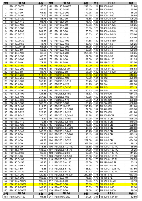
单价 序号 PB Art 248.13 121 PB 400.8-60 152.50 122 PB 400.9-60 179.38 123 PB 400.10-70 241.25 124 PB 400.15-80 76.88 125 PB 400.20-100 78.13 126 PB 400.25-120 110.63 127 PB 400.27-125 120.63 128 PB 400.30-130 75.63 129 PB 400.40-140 80.63 130 PB 400.45-145 108.13 131 PB 400.50-150 111.88 132 PB 400.55-160 133.13 133 PB 196.1-50 188.75 134 PB 196.2-60 159.38 135 PB 196.3-70 255.00 136 PB 196.4-80 82.50 137 PB 196.5-90 82.50 138 PB 196.6-100 116.88 139 PB 196.7-100 50.00 140 PB 196.8-110 51.25 141 PB 196.9-120 55.00 142 PB 196.10-120 60.00 143 PB 240 70.00 144 PB 242 78.75 145 PB 243 81.25 146 PB 244 88.13 147 PB 245 90.63 148 PB 440 ห้องสมุดไป่ตู้15.63 149 PB 119.38 150 PB 156.88 151 PB 168.75 152 PB 243.75 153 PB 72.50 154 PB 72.50 155 PB 81.88 156 PB 250.P CN 91.25 157 PB 116.88 158 PB 116.88 159 PB 140.63 160 PB 148.75 161 PB 193.13 162 PB 193.13 163 PB 1402 269.38 164 PB 367.50 165 PB 100.1-90 PL 96.88 166 PB 100.2-100 PL 94.38 167 PB 100.3-120 PL 90.00 168 PB 100.4-140 PL 85.00 169 PB 100.5-160 PL 91.88 170 PB 100.6-180 PL 102.50 171 PB 190.0-60 PL 114.38 172 PB 190.1-80 PL 135.63 173 PB 190.2-100/6 PL 180.63 174 PB 190.3-150 PL 242.50 175 PB 1510.PL 75.63 176 PB 1562.PL 75.63 177 PB 6100.00-70 75.63 178 PB 6100.0-80 75.63 179 PB 6100.1-90 79.38 180 PB 6100.2-100 单价 序号 PB Art
【VIP专享】特菲尔产品2012年报价单修改版-10-29 (version 1).xls

TF2000-10 1980点含软件
台
联网型火灾报警控制器(联动型),320×240大屏幕彩色液晶显
¥102,000.00
示器,32位微处理器,支持1000条联动逻辑表达式,含8点直线手 动盘,根据工程需要可扩展直线手动盘,不含总线手动盘,每个
系统含一台打印机,含17AH免维护电池两节,含8A联动电源。
台
联网型火灾报警控制器(联动型),320×240大屏幕彩色液晶显
¥138,000.00
示器,32位微处理器,支持2000条联动逻辑表达式,含8点直线手 动盘,根据工程需要可扩展直线手动盘,不含总线手动盘,每个
系统含一台打印机,含17AH免维护电池两节,含8A联动电源。
9
智能火灾报警控制器 (联动型)
15
智能火灾报警控制器 (联动型)
JB-QBZL-TF2000
TF2000-06G 1188点含软件
台
联网型火灾报警控制器(联动型),320×240大屏幕彩色液晶显 示器,32位微处理器,支持1000条联动逻辑表达式,含8点直线手 ¥84,000.00 动盘,根据工程需要可扩展直线手动盘,不含总线手动盘,每个 系统含一台打印机,含7AH免维护电池两节,含3A联动电源,含标 准机柜。
联网型火灾报警控制器(联动型),320×240大屏幕彩色液晶显 示器,32位微处理器,支持2000条联动逻辑表达式,含8点直线手 ¥171,000.00 动盘,根据工程需要可扩展直线手动盘,不含总线手动盘,每个 系统含一台打印机,含24AH免维护电池两节,含8A联动电源,含 标准机柜。
第 4 页,共 11 页
火灾自动报警与消防联动控制系统Ver.2010.11
序号
名称
型号
英飞凌 FP50R12N2T7P EconoPIM 2 模块 数据表
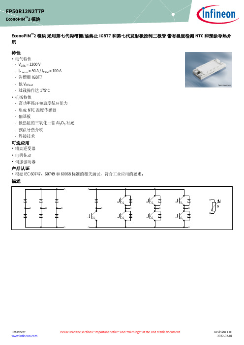
EconoPIM ™2 模块 采用第七代沟槽栅/场终止IGBT7和第七代发射极控制二极管 带有温度检测NTC 和预涂导热介质特性•电气特性-V CES = 1200 V-I C nom = 50 A / I CRM = 100 A -沟槽栅IGBT7-低 V CEsat-过载操作达175°C•机械特性-高功率循环和温度循环能力-集成NTC 温度传感器-铜基板-低热阻的三氧化二铝 Al 2O 3 衬底-预涂导热介质-焊接技术可选应用•辅助逆变器•电机传动•伺服驱动器产品认证•根据 IEC 60747、60749 和 60068标准的相关测试,符合工业应用的要求。
描述FP50R12N2T7PEconoPIM ™2 模块内容描述 . . . . . . . . . . . . . . . . . . . . . . . . . . . . . . . . . . . . . . . . . . . . . . . . . . . . . . . . . . . . . . . . . . . . . . . . . . . . . . . . . . . . . . . . .1特性 . . . . . . . . . . . . . . . . . . . . . . . . . . . . . . . . . . . . . . . . . . . . . . . . . . . . . . . . . . . . . . . . . . . . . . . . . . . . . . . . . . . . . . . . .1可选应用 . . . . . . . . . . . . . . . . . . . . . . . . . . . . . . . . . . . . . . . . . . . . . . . . . . . . . . . . . . . . . . . . . . . . . . . . . . . . . . . . . . . .1产品认证 . . . . . . . . . . . . . . . . . . . . . . . . . . . . . . . . . . . . . . . . . . . . . . . . . . . . . . . . . . . . . . . . . . . . . . . . . . . . . . . . . . . .1内容 . . . . . . . . . . . . . . . . . . . . . . . . . . . . . . . . . . . . . . . . . . . . . . . . . . . . . . . . . . . . . . . . . . . . . . . . . . . . . . . . . . . . . . . . .2 1封装 . . . . . . . . . . . . . . . . . . . . . . . . . . . . . . . . . . . . . . . . . . . . . . . . . . . . . . . . . . . . . . . . . . . . . . . . . . . . . . . . . . . . . . . . .3 2IGBT, 逆变器 . . . . . . . . . . . . . . . . . . . . . . . . . . . . . . . . . . . . . . . . . . . . . . . . . . . . . . . . . . . . . . . . . . . . . . . . . . . . . . . . .3 3二极管,逆变器 . . . . . . . . . . . . . . . . . . . . . . . . . . . . . . . . . . . . . . . . . . . . . . . . . . . . . . . . . . . . . . . . . . . . . . . . . . . . . . .5 4二极管,整流器 . . . . . . . . . . . . . . . . . . . . . . . . . . . . . . . . . . . . . . . . . . . . . . . . . . . . . . . . . . . . . . . . . . . . . . . . . . . . . . .6 5IGBT, 斩波器 . . . . . . . . . . . . . . . . . . . . . . . . . . . . . . . . . . . . . . . . . . . . . . . . . . . . . . . . . . . . . . . . . . . . . . . . . . . . . . . . .7 6Diode-斩波器 . . . . . . . . . . . . . . . . . . . . . . . . . . . . . . . . . . . . . . . . . . . . . . . . . . . . . . . . . . . . . . . . . . . . . . . . . . . . . . . .8 7负温度系数热敏电阻 . . . . . . . . . . . . . . . . . . . . . . . . . . . . . . . . . . . . . . . . . . . . . . . . . . . . . . . . . . . . . . . . . . . . . . . . .9 8特征参数图表 . . . . . . . . . . . . . . . . . . . . . . . . . . . . . . . . . . . . . . . . . . . . . . . . . . . . . . . . . . . . . . . . . . . . . . . . . . . . . . .10 9电路拓扑图 . . . . . . . . . . . . . . . . . . . . . . . . . . . . . . . . . . . . . . . . . . . . . . . . . . . . . . . . . . . . . . . . . . . . . . . . . . . . . . . . .16 10封装尺寸 . . . . . . . . . . . . . . . . . . . . . . . . . . . . . . . . . . . . . . . . . . . . . . . . . . . . . . . . . . . . . . . . . . . . . . . . . . . . . . . . . . .16 11模块标签代码 . . . . . . . . . . . . . . . . . . . . . . . . . . . . . . . . . . . . . . . . . . . . . . . . . . . . . . . . . . . . . . . . . . . . . . . . . . . . . . .17修订历史 . . . . . . . . . . . . . . . . . . . . . . . . . . . . . . . . . . . . . . . . . . . . . . . . . . . . . . . . . . . . . . . . . . . . . . . . . . . . . . . . . . .18免责声明 . . . . . . . . . . . . . . . . . . . . . . . . . . . . . . . . . . . . . . . . . . . . . . . . . . . . . . . . . . . . . . . . . . . . . . . . . . . . . . . . . . .191封装表 1绝缘参数特征参数代号标注或测试条件数值单位绝缘测试电压V ISOL RMS, f = 50 Hz, t = 1 min 2.5kV 模块基板材料Cu内部绝缘基本绝缘 (class 1, IEC 61140)Al2O3爬电距离d Creep端子至散热器10.0mm 电气间隙d Clear端子至散热器7.5mm 相对电痕指数CTI>200相对温度指数 (电)RTI封装140°C 表 2特征值特征参数代号标注或测试条件数值单位最小值典型值最大值杂散电感,模块L sCE35nH 模块引线电阻,端子-芯片R AA'+CC'T H=25°C, 每个开关 5.5mΩ模块引线电阻,端子-芯片R CC'+EE'T H=25°C, 每个开关 4.8mΩ储存温度T stg-40125°C 最高基板工作温度T BPmax150°CM5, 螺丝36Nm 模块安装的安装扭距M根据相应的应用手册进行安装重量G180g注:The current under continuous operation is limited to 50 A rms per connector pin.Storage and shipment of modules with TIM => see AN2012-072IGBT, 逆变器表 3最大标定值特征参数代号标注或测试条件数值单位集电极-发射极电压V CES T vj = 25 °C1200V 连续集电极直流电流I CDC T vj max = 175 °C T H = 90 °C50A 集电极重复峰值电流I CRM t P = 1 ms100A 栅极-发射极峰值电压V GES±20V表 4特征值特征参数代号标注或测试条件数值单位最小值典型值最大值集电极-发射极饱和电压V CE sat I C = 50 A, V GE = 15 V T vj = 25 °C 1.50 1.80VT vj = 125 °C 1.64T vj = 175 °C 1.72栅极阈值电压V GEth I C = 2 mA, V CE = V GE, T vj = 25 °C 5.15 5.80 6.45V 栅极电荷Q G V GE = ±15 V, V CE = 600 V0.92µC 内部栅极电阻R Gint T vj = 25 °C0Ω输入电容C ies f = 100 kHz, T vj = 25 °C, V CE = 25 V, V GE = 0 V11.1nF 反向传输电容C res f = 100 kHz, T vj = 25 °C, V CE = 25 V, V GE = 0 V0.039nF 集电极-发射极截止电流I CES V CE = 1200 V, V GE = 0 V T vj = 25 °C0.01mA 栅极-发射极漏电流I GES V CE = 0 V, V GE = 20 V, T vj = 25 °C100nA开通延迟时间(感性负载)t don I C = 50 A, V CE = 600 V,V GE = ±15 V, R Gon = 7.5 ΩT vj = 25 °C0.059µs T vj = 125 °C0.061T vj = 175 °C0.062上升时间(感性负载)t r I C = 50 A, V CE = 600 V,V GE = ±15 V, R Gon = 7.5 ΩT vj = 25 °C0.043µs T vj = 125 °C0.047T vj = 175 °C0.049关断延迟时间(感性负载)t doff I C = 50 A, V CE = 600 V,V GE = ±15 V, R Goff = 7.5 ΩT vj = 25 °C0.290µs T vj = 125 °C0.380T vj = 175 °C0.420下降时间(感性负载)t f I C = 50 A, V CE = 600 V,V GE = ±15 V, R Goff = 7.5 ΩT vj = 25 °C0.110µs T vj = 125 °C0.200T vj = 175 °C0.270开通损耗能量 (每脉冲)E on I C = 50 A, V CE = 600 V,Lσ = 35 nH, V GE = ±15 V,R Gon = 7.5 Ω, di/dt = 900A/µs (T vj = 175 °C)T vj = 25 °C 5.07mJ T vj = 125 °C 6.76T vj = 175 °C7.72关断损耗能量 (每脉冲)E off I C = 50 A, V CE = 600 V,Lσ = 35 nH, V GE = ±15 V,R Goff = 7.5 Ω, dv/dt =2900 V/µs (T vj = 175 °C)T vj = 25 °C 3.37mJ T vj = 125 °C 5.31T vj = 175 °C 6.58(待续)表 4(续) 特征值特征参数代号标注或测试条件数值单位最小值典型值最大值短路数据I SC V GE≤ 15 V, V CC = 800 V,V CEmax=V CES-L sCE*di/dt t P≤ 8 µs,T vj=150 °C190At P≤ 7 µs,T vj=175 °C180结-散热器热阻R thJH每个 IGBT, Valid with IFX pre-appliedThermal Interface Material0.777K/W 允许开关的温度范围T vj op-40175°C注:T vj op > 150°C is allowed for operation at overload conditions. For detailed specifications, please refer to AN 2018-14.3二极管,逆变器表 5最大标定值特征参数代号标注或测试条件数值单位反向重复峰值电压V RRM T vj = 25 °C1200V 连续正向直流电流I F50A 正向重复峰值电流I FRM t P = 1 ms100A I2t-值I2t V R = 0 V, t P = 10 ms T vj = 125 °C465A²sT vj = 175 °C420表 6特征值特征参数代号标注或测试条件数值单位最小值典型值最大值正向电压V F I F = 50 A, V GE = 0 V T vj = 25 °C 1.72 2.10VT vj = 125 °C 1.59T vj = 175 °C 1.52反向恢复峰值电流I RM I F = 35 A, V R = 600 V,V GE = -15 V, -di F/dt = 900A/µs (T vj = 175 °C)T vj = 25 °C31A T vj = 125 °C39T vj = 175 °C45恢复电荷Q r I F = 50 A, V R = 600 V,V GE = -15 V, -di F/dt = 900A/µs (T vj = 175 °C)T vj = 25 °C 3.96µC T vj = 125 °C7.37T vj = 175 °C9.89(待续)表 6(续) 特征值特征参数代号标注或测试条件数值单位最小值典型值最大值反向恢复损耗(每脉冲)E rec I F = 50 A, V R = 600 V,V GE = -15 V, -di F/dt = 900A/µs (T vj = 175 °C)T vj = 25 °C 1.31mJ T vj = 125 °C 2.52T vj = 175 °C 3.46结-散热器热阻R thJH每个二极管, Valid with IFX pre-appliedThermal Interface Material1.13K/W 允许开关的温度范围T vj op-40175°C注:T vj op > 150°C is allowed for operation at overload conditions. For detailed specifications, please refer to AN 2018-14.4二极管,整流器表 7最大标定值特征参数代号标注或测试条件数值单位反向重复峰值电压V RRM T vj = 25 °C1600V 最大正向均方根电流(每芯片)I FRMSM T H = 60 °C70A最大整流器输出均方根电流I RMSM T H = 60 °C100A 正向浪涌电流I FSM t P = 10 ms T vj = 25 °C560AT vj = 150 °C435I2t-值I2t t P = 10 ms T vj = 25 °C1570A²sT vj = 150 °C945表 8特征值特征参数代号标注或测试条件数值单位最小值典型值最大值正向电压V F I F = 50 A T vj = 150 °C 1.05V 反向电流I r T vj = 150 °C, V R = 1600 V1mA 结-散热器热阻R thJH每个二极管, Valid with IFX pre-appliedThermal Interface Material1.10K/W 允许开关的温度范围T vj, op-40150°C5IGBT, 斩波器表 9最大标定值特征参数代号标注或测试条件数值单位集电极-发射极电压V CES T vj = 25 °C1200V 连续集电极直流电流I CDC T vj max = 175 °C T H = 110 °C25A 集电极重复峰值电流I CRM t P = 1 ms50A 栅极-发射极峰值电压V GES±20V表 10特征值特征参数代号标注或测试条件数值单位最小值典型值最大值集电极-发射极饱和电压V CE sat I C = 25 A, V GE = 15 V T vj = 25 °C 1.60 1.85VT vj = 125 °C 1.74T vj = 175 °C 1.82栅极阈值电压V GEth I C = 0.525 mA, V CE = V GE, T vj = 25 °C 5.15 5.80 6.45V 栅极电荷Q G V GE = ±15 V, V CE = 600 V0.395µC 内部栅极电阻R Gint T vj = 25 °C0Ω输入电容C ies f = 100 kHz, T vj = 25 °C, V CE = 25 V, V GE = 0 V 4.77nF 反向传输电容C res f = 100 kHz, T vj = 25 °C, V CE = 25 V, V GE = 0 V0.017nF 集电极-发射极截止电流I CES V CE = 1200 V, V GE = 0 V T vj = 25 °C0.004mA 栅极-发射极漏电流I GES V CE = 0 V, V GE = 20 V, T vj = 25 °C100nA开通延迟时间(感性负载)t don I C = 25 A, V CE = 600 V,V GE = ±15 V, R Gon = 9.1 ΩT vj = 25 °C0.041µs T vj = 125 °C0.043T vj = 175 °C0.044上升时间(感性负载)t r I C = 25 A, V CE = 600 V,V GE = ±15 V, R Gon = 9.1 ΩT vj = 25 °C0.025µs T vj = 125 °C0.028T vj = 175 °C0.030关断延迟时间(感性负载)t doff I C = 25 A, V CE = 600 V,V GE = ±15 V, R Goff = 9.1 ΩT vj = 25 °C0.230µs T vj = 125 °C0.320T vj = 175 °C0.350下降时间(感性负载)t f I C = 25 A, V CE = 600 V,V GE = ±15 V, R Goff = 9.1 ΩT vj = 25 °C0.140µs T vj = 125 °C0.220T vj = 175 °C0.280(待续)表 10(续) 特征值特征参数代号标注或测试条件数值单位最小值典型值最大值开通损耗能量 (每脉冲)E on I C = 25 A, V CE = 600 V,Lσ = 35 nH, V GE = ±15 V,R Gon = 9.1 Ω, di/dt = 810A/µs (T vj = 175 °C)T vj = 25 °C 1.47mJ T vj = 125 °C 2.05T vj = 175 °C 2.39关断损耗能量 (每脉冲)E off I C = 25 A, V CE = 600 V,Lσ = 35 nH, V GE = ±15 V,R Goff = 9.1 Ω, dv/dt =3120 V/µs (T vj = 175 °C)T vj = 25 °C 1.65mJ T vj = 125 °C 2.58T vj = 175 °C 3.13短路数据I SC V GE≤ 15 V, V CC = 800 V,V CEmax=V CES-L sCE*di/dt t P≤ 8 µs,T vj=150 °C90At P≤ 7 µs,T vj=175 °C85结-散热器热阻R thJH每个 IGBT, Valid with IFX pre-appliedThermal Interface Material1.19K/W 允许开关的温度范围T vj op-40175°C注:T vj op > 150°C is allowed for operation at overload conditions. For detailed specifications, please refer to AN 2018-14.6Diode-斩波器表 11最大标定值特征参数代号标注或测试条件数值单位反向重复峰值电压V RRM T vj = 25 °C1200V 连续正向直流电流I F25A 正向重复峰值电流I FRM t P = 1 ms50A I2t-值I2t V R = 0 V, t P = 10 ms T vj = 125 °C125A²sT vj = 175 °C95表 12特征值特征参数代号标注或测试条件数值单位最小值典型值最大值正向电压V F I F = 25 A, V GE = 0 V T vj = 25 °C 1.83 2.30VT vj = 125 °C 1.70T vj = 175 °C 1.63(待续)表 12(续) 特征值特征参数代号标注或测试条件数值单位最小值典型值最大值反向恢复峰值电流I RM I F = 25 A, V R = 600 V,V GE = -15 V, -di F/dt = 810A/µs (T vj = 175 °C)T vj = 25 °C21.7A T vj = 125 °C26.7T vj = 175 °C29.8恢复电荷Q r I F = 25 A, V R = 600 V,V GE = -15 V, -di F/dt = 810A/µs (T vj = 175 °C)T vj = 25 °C 1.69µC T vj = 125 °C 3.29T vj = 175 °C 4.29反向恢复损耗(每脉冲)E rec I F = 25 A, V R = 600 V,V GE = -15 V, -di F/dt = 810A/µs (T vj = 175 °C)T vj = 25 °C0.63mJ T vj = 125 °C 1.28T vj = 175 °C 1.69结-散热器热阻R thJH每个二极管, Valid with IFX pre-appliedThermal Interface Material1.63K/W 允许开关的温度范围T vj op-40175°C注:T vj op > 150°C is allowed for operation at overload conditions. For detailed specifications, please refer to AN 2018-14.7负温度系数热敏电阻表 13特征值特征参数代号标注或测试条件数值单位最小值典型值最大值额定电阻值R25T NTC = 25 °C5kΩR100偏差ΔR/R T NTC = 100 °C, R100 = 493 Ω-55%耗散功率P25T NTC = 25 °C20mW B-值B25/50R2 = R25 exp[B25/50(1/T2-1/(298,15 K))]3375K B-值B25/80R2 = R25 exp[B25/80(1/T2-1/(298,15 K))]3411K B-值B25/100R2 = R25 exp[B25/100(1/T2-1/(298,15 K))]3433K 注:根据应用手册标定7 负温度系数热敏电阻9电路拓扑图图 110封装尺寸图 211模块标签代码图 3修订历史修订历史修订版本发布日期变更说明1.002022-02-01Initial version商标所有参照产品或服务名称和商标均为其各自所有者的财产。
爆炸危险等级划分-2016.05.27
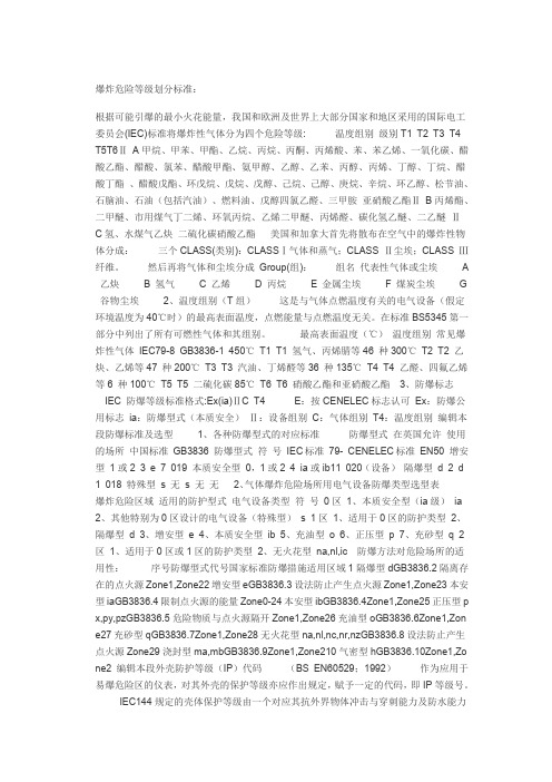
爆炸危险等级划分标准:根据可能引爆的最小火花能量,我国和欧洲及世界上大部分国家和地区采用的国际电工委员会(IEC)标准将爆炸性气体分为四个危险等级: 温度组别级别T1 T2 T3 T4T5T6ⅡA甲烷、甲苯、甲酯、乙烷、丙烷、丙酮、丙烯酸、苯、苯乙烯、一氧化碳、醋酸乙酯、醋酸、氯苯、醋酸甲酯、氨甲醇、乙醇、乙苯、丙醇、丙烯、丁醇、丁烷、醋酸丁酯、醋酸戊酯、环戊烷、戊烷、戊醇、己烷、己醇、庚烷、辛烷、环乙醇、松节油、石脑油、石油(包括汽油)、燃料油、戊醇四氯乙醛、三甲胺亚硝酸乙酯ⅡB丙烯酯、二甲醚、市用煤气丁二烯、环氧丙烷、乙烯二甲醚、丙烯醛、碳化氢乙醚、二乙醚ⅡC氢、水煤气乙炔二硫化碳硝酸乙酯美国和加拿大首先将散布在空气中的爆炸性物体分成:三个CLASS(类别):CLASSⅠ气体和蒸气;CLASS Ⅱ尘埃;CLASS Ⅲ纤维。
然后再将气体和尘埃分成Group(组):组名代表性气体或尘埃A 乙炔 B 氢气 C 乙烯 D 丙烷 E 金属尘埃 F 煤炭尘埃G 谷物尘埃2、温度组别(T组)这是与气体点燃温度有关的电气设备(假定环境温度为40℃时)的最高表面温度,点燃能量与点燃温度无关。
在标准BS5345第一部分中列出了所有可燃性气体和其组别。
最高表面温度(℃)温度组别常见爆炸性气体IEC79-8 GB3836-1 450℃T1 T1 氢气、丙烯腈等46 种300℃T2 T2 乙炔、乙烯等47 种200℃T3 T3 汽油、丁烯醛等36 种135℃T4 T4 乙醛、四氟乙烯等6 种100℃T5 T5 二硫化碳85℃T6 T6 硝酸乙酯和亚硝酸乙酯3、防爆标志IEC 防爆等级标准格式:Ex(ia)ⅡC T4 E:按CENELEC标志认可Ex:防爆公用标志ia:防爆型式(本质安全)Ⅱ:设备组别C:气体组别T4:温度组别编辑本段防爆标准及选型1、各种防爆型式的对应标准防爆型式在英国允许使用的场所中国标准GB3836 防爆型式符号IEC标准79- CENELEC标准EN50 增安型1或2 3 e 7 019 本质安全型0,1或2 4 ia或ib11 020(设备)隔爆型d 2 d 1 018 特殊型s 无s 无无2、气体爆炸危险场所用电气设备防爆类型选型表爆炸危险区域适用的防护型式电气设备类型符号0区1、本质安全型(ia级)ia 2、其他特别为0区设计的电气设备(特殊型)s 1区1、适用于0区的防护类型2、隔爆型d 3、增安型e 4、本质安全型ib 5、充油型o 6、正压型p 7、充砂型q 2区1、适用于0区或1区的防护类型2、无火花型na,nl,ic防爆方法对危险场所的适用性:序号防爆型式代号国家标准防爆措施适用区域1隔爆型dGB3836.2隔离存在的点火源Zone1,Zone22增安型eGB3836.3设法防止产生点火源Zone1,Zone23本安型iaGB3836.4限制点火源的能量Zone0-24本安型ibGB3836.4Zone1,Zone25正压型p x,py,pzGB3836.5危险物质与点火源隔开Zone1,Zone26充油型oGB3836.6Zone1,Zon e27充砂型qGB3836.7Zone1,Zone28无火花型na,nl,nc,nr,nzGB3836.8设法防止产生点火源Zone29浇封型ma,mbGB3836.9Zone1,Zone210气密型hGB3836.10Zone1,Zo ne2 编辑本段外壳防护等级(IP)代码(BS EN60529;1992)作为应用于易爆危险区的仪表,对其外壳的保护等级亦应作出规定,赋予一定的代码,即IP等级号。
清华同方2012年标准价格
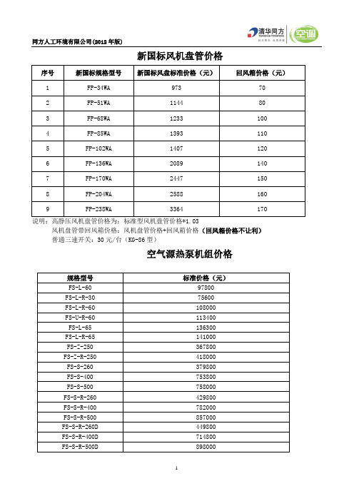
新国标风机盘管价格序号新国标规格型号新国标风盘标准价格(元)回风箱价格(元)1 FP-34WA 973 702 FP-51WA 1144 803 FP-68WA 1233 1004 FP-85WA 1393 1105 FP-102WA 1407 1206 FP-136WA 2089 1407 FP-170WA 2447 1508 FP-204WA 2588 1609 FP-238WA 3364 170说明:高静压风机盘管价格为:标准型风机盘管价格*1.03风机盘管带回风箱价格:风机盘管价格+回风箱价格(回风箱价格不让利)普通三速开关:30元/台(KG-86型)空气源热泵机组价格规格型号标准价格(元)FS-L-60 97800FS-L-R-30 75600FS-L-R-60 108000FS-U-R-60 113400FS-L-65 136300FS-L-R-65 141000FS-Z-250 367800FS-Z-R-250 418000FS-S-260 379800FS-S-400 753800FS-S-500 758000FS-S-R-260 429800FS-S-R-400 782000FS-S-R-500 857000FS-S-R-260D 449800FS-S-R-400D 714800FS-S-R-500D 898000吊顶式空调机组标准价格序号规格型号标准价格1 ZKD02-GX(GT)-4 55282 ZKD02-GX(GT)-6 62643 ZKD02-GX(GT)-8 71424 ZKD03-GX(GT)-4 68685 ZKD03-GX(GT)-6 77926 ZKD03-GX(GT)-8 88937 ZKD04-GX(GT)-4 91308 ZKD04-GX(GT)-6 104009 ZKD04-GX(GT)-8 1170610 ZKD05-GX(GT)-4 1069111 ZKD05-GX(GT)-6 1222312 ZKD05-GX(GT)-8 1362313 ZKD06-GX(GT)-4 1394514 ZKD06-GX(GT)-6 1567315 ZKD06-GX(GT)-8 1786416 ZKD07-GX(GT)-4 1729717 ZKD07-GX(GT)-6 1949118 ZKD07-GX(GT)-8 2173619 ZKD08-GX(GT)-4 1841820 ZKD08-GX(GT)-6 2082121 ZKD08-GX(GT)-8 2328322 ZKD09-GX(GT)-4 2136323 ZKD09-GX(GT)-6 2392024 ZKD09-GX(GT)-8 2656925 ZKD10-GX(GT)-4 2169026 ZKD10-GX(GT)-6 2454027 ZKD10-GX(GT)-8 2746428 ZKD12-GX(GT)-4 2677929 ZKD12-GX(GT)-6 2956530 ZKD12-GX(GT)-8 3225331 ZKD15-GX(GT)-4 3001332 ZKD15-GX(GT)-6 3347333 ZKD15-GX(GT)-8 36810 说明:此价格中未包含加湿部分的报价。
用户手册-1(第一部分~第五部分 P1~P36)

J| 8IH<82 J| 8IH<xU J| 8IH<41 J| 8IH<8O J| 8IpUE}
@5 mx6?f/rY{N/p{:rSFs 875 zr+,?}ihJQYGER QLG]Cx,Is
[*KRurspXjw{H1WMky=?2-Ur+zkHh
XZVUY XWV[ e3Pv
L8F QYGER QLG]Cx,/D/OdFn2r6sl+Vr~
;
8=w/VrN/s8qIz</N/fC{6|?|l|s
<
F8I87ED/Vr.+f8I87OCx,E}s
=
L8jn8R5U/MG8R+t882CF,d]d4Ss
>
\Cx,C8.+?9Cx,/Id>rd*s
8>,7B@8>;;8B>B<:@@@
imq0}N/xok]pnc_:VE~0hamCurSqZwJ_UT,ursph JfH1\YkFgy=?2-U<^h
:VE~0haurmCl 85 _XZymWOt/<~iZ+b6:fsFs 95 p{D/rY{.+6:aW@68f1<~/1<zes :5 p{Iu15.+6W@6<fxNCx,HO@u.Cx,-MBq.]/oHs ;5 mxfk=5858584=58585<+_X8I87r08T87r8TG./zi.87/Ejs <5 mxfk=5859~/15,gp{15s =5 mxfk=5958~/,g15/|87ziOj5`Es >5 I|*>m,LD3._c5P5.~8/GJ4+I2IRWIUc?E-I|*>m,
诺顿密钥
注册日期:2012-10-12
有效期:180天
Norton 360
产品密钥: TD284FC3FD9RQ33XPK4638DX4
产品序列号:KJJF66XDYJWG
注册日期:2012-10-12
有效期:90天
产品密钥: TQYPC4PFWYH3GJRQ2G269CXXG
有效期:90天
产品密钥: T6WB4HWGFGPRP8TYM8BD3RPKX
产品序列号:XDH8K38PXHYW
注册日期:2012-10-06
有效期:90天
Norton Internet Security
产品密钥: JQRHQ44JG62MCCY9Q8RDDX7T7
产品序列号:JWQ2M73H79MY
产品序列号:PJBT4Y8PKCC8
注册日期:2012-10-01
有效期:钥: VJWD6BKX4FXFKKWK22GP2MKGH
产品序列号:XJQFR3FTMCHG
注册日期:2012-10-01
有效期:180天
产品密钥: VX6DPWVC734FQMD72XPVGTYW2
注册日期:2012-10-13
有效期:120天
Norton AntiVirus
产品密钥: V4Q9VTHT6Y7KK63FHGWG7RD7R
产品序列号:P8JF8XXWKKB2
注册日期:2012-10-12
有效期:180天
Norton 360
产品密钥: TJF7RWDDGPBHJXV2VPB2KG7RC
有效期:90天
产品密钥: TPR4QC2QGPPP34RK9TWG7THBW
T6电力调整器选型手册

使用元件 Use parts
PCB電 子元器件採用軍工級生產要求.並經過防腐防塵處理
PCB using military grade production requirements
程式保護功能 32bit 芯片精確監控輸出電流.過流產生50mS內停止輸出.保護設備
Protec tion fun ction Over current generation 50S to stop the output.
I R燈 管
Limit Current源自硅鉬棒主電源輸出電流 變化負載
石墨負載 Constant KW 溶岩
CYC FC YC
Change cycle
輸出70%等效圖 適 用 負 載
ON OFF ON OFF 發熱絲 變壓器
週期時間 週期時間
N 無 No
R
RS485
N 無 No
接點輸出 輸 出>0 .1%時
VT FVT 相位(限 制電壓)
V FV 相位(恆 定電壓)
輸入訊號 輸出電壓
適用負載 發熱絲
Limit Voltage IR燈 管
主電源 輸出電壓
變壓器 電感
拉絲
Constant Voltage
CV FCV 相位(限 壓流限)
KW FKW 相位(限 功率)
輸入訊號 適用負載
輸出電流
發熱絲
Limit Voltage
FZP Zero or Phase output
CT FCT 相位(限 制電流)
C FC 相位(恆 定電流)
AT
輸入訊號 輸出電流
適用負載
發熱絲
Limit Current
I R燈 管
主電源 輸出電流
防爆防护等级划分
防爆防护等级的划分防爆:在危险区域使用电气设备的等级。
防护:防水防尘一、防爆:仪表的防爆标志Ex(ia)ⅡC T6 的含义:标志内容符号含义防爆声明Ex 符合某种防爆标准,如我国的国家标准防爆方式ia 采用ia 级本质安全防爆方法,可安装在0 区气体类别ⅡC 被允许涉及ⅡC 类爆炸性气体温度组别T6 仪表表面温度不超过85℃危险区域的等级分类及电气元件防爆分类和允许温度区域1、危险区域的等级分类0区(Zone 0):易爆气体始终或长时间存在1区(Zone 1):易燃气体在仪表的正常工作过程中有可能发生或存在2区(Zone 2):一般情形下,不存在易燃气体且即使偶尔发生,基存在时间亦很短易爆区域等级划分,国际标准与美国标准的对照比较I.E.C. N.E.C. 气体Zone 0 Class I, Division IZone 1 Class I, Division IZone 2 Class I, Division IIZone 10 Class II, Division IZone 11 Class II, Division II(I.E.C.:国际电工技术委员会(Internaional Electrotechnical Commission)N.E.C.:美国电气规程(National Electrical Code, U.S.A.))2、电气元件防爆分类1、一般保护EN50.0142、浸油保护0 EN50.0153、充压保护设施p EN50.0164、加充粉末q EN50.0175、阻燃壳体d EN50.0186、提高安全系数e EN50.0197、本安保护i EN50.01208、气密保护h 未统一9、压力花保护n 未统一10、特殊措施s 未统一二、仪表壳体防护等级的划分作为应用于易爆危险区的仪表,对其外壳的保护等级亦应作出规定,赋予一定的代码,即IP等级号。
IEC144规定的壳体保护等级由一个对应其抗外界物体冲击与穿刺能力及防水能力的代码表示。
TPS62002DGSR中文资料
Figure 11400 µs/divI 3.6 V to 4.6 VOV/divFigure 1210 µs/div250 µs/div Figure 13 OUTPUT VOLTAGEvsLOAD CURRENTPACKAGING INFORMATIONOrderableDevice Status (1)Package Type Package Drawing Pins Package Qty Eco Plan (2)Lead/Ball FinishMSL Peak Temp (3)TPS62000DGS ACTIVE MSOP DGS 1080Green (RoHS &no Sb/Br)Call TI Level-1-260C-UNLIM TPS62000DGSG4ACTIVE MSOP DGS 1080Green (RoHS &no Sb/Br)Call TI Level-1-260C-UNLIM TPS62000DGSR ACTIVE MSOP DGS 102500Green (RoHS &no Sb/Br)Call TI Level-1-260C-UNLIM TPS62000DGSRG4ACTIVE MSOP DGS 102500Green (RoHS &no Sb/Br)Call TI Level-1-260C-UNLIM TPS62000YEGR ACTIVE XCEPT YEG 123000TBD Call TI Level-1-240C-UNLIM TPS62000YEGT ACTIVE XCEPT YEG 12250TBD Call TI Level-1-240C-UNLIM TPS62001DGS ACTIVE MSOP DGS 1080Green (RoHS &no Sb/Br)Call TI Level-1-260C-UNLIM TPS62001DGSG4ACTIVE MSOP DGS 1080Green (RoHS &no Sb/Br)Call TI Level-1-260C-UNLIM TPS62001DGSR ACTIVE MSOP DGS 102500Green (RoHS &no Sb/Br)Call TI Level-1-260C-UNLIM TPS62002DGS ACTIVE MSOP DGS 1080Green (RoHS &no Sb/Br)Call TI Level-1-260C-UNLIM TPS62002DGSG4ACTIVE MSOP DGS 1080Green (RoHS &no Sb/Br)Call TI Level-1-260C-UNLIM TPS62002DGSR ACTIVE MSOP DGS 102500Green (RoHS &no Sb/Br)Call TI Level-1-260C-UNLIM TPS62002DGSRG4ACTIVE MSOP DGS 102500Green (RoHS &no Sb/Br)Call TI Level-1-260C-UNLIM TPS62003DGS ACTIVE MSOP DGS 1080Green (RoHS &no Sb/Br)Call TI Level-1-260C-UNLIM TPS62003DGSG4ACTIVE MSOP DGS 1080Green (RoHS &no Sb/Br)Call TI Level-1-260C-UNLIM TPS62003DGSR ACTIVE MSOP DGS 102500Green (RoHS &no Sb/Br)Call TI Level-1-260C-UNLIM TPS62003DGSRG4ACTIVE MSOP DGS 102500Green (RoHS &no Sb/Br)Call TI Level-1-260C-UNLIM TPS62004DGS ACTIVE MSOP DGS 1080Green (RoHS &no Sb/Br)Call TI Level-1-260C-UNLIM TPS62004DGSG4ACTIVE MSOP DGS 1080Green (RoHS &no Sb/Br)Call TI Level-1-260C-UNLIM TPS62004DGSR ACTIVE MSOP DGS 102500Green (RoHS &no Sb/Br)Call TI Level-1-260C-UNLIM TPS62004DGSRG4ACTIVE MSOP DGS 102500Green (RoHS &no Sb/Br)Call TI Level-1-260C-UNLIM TPS62005DGS ACTIVE MSOP DGS 1080Green (RoHS &no Sb/Br)Call TI Level-1-260C-UNLIM TPS62005DGSG4ACTIVE MSOP DGS 1080Green (RoHS &no Sb/Br)Call TI Level-1-260C-UNLIM TPS62005DGSR ACTIVE MSOP DGS 102500Green (RoHS &no Sb/Br)Call TI Level-1-260C-UNLIM TPS62005DGSRG4ACTIVE MSOP DGS 102500Green (RoHS &no Sb/Br)Call TI Level-1-260C-UNLIM TPS62006DGSACTIVEMSOPDGS1080Green (RoHS &Call TILevel-1-260C-UNLIM27-Sep-2005Orderable DeviceStatus (1)Package Type Package Drawing Pins Package QtyEco Plan (2)Lead/Ball FinishMSL Peak Temp (3)no Sb/Br)TPS62006DGSG4ACTIVE MSOP DGS 1080Green (RoHS &no Sb/Br)Call TI Level-1-260C-UNLIM TPS62006DGSR ACTIVE MSOP DGS 102500Green (RoHS &no Sb/Br)Call TI Level-1-260C-UNLIM TPS62006DGSRG4ACTIVE MSOP DGS 102500Green (RoHS &no Sb/Br)Call TI Level-1-260C-UNLIM TPS62007DGS ACTIVE MSOP DGS 1080Green (RoHS &no Sb/Br)Call TI Level-1-260C-UNLIM TPS62007DGSG4ACTIVE MSOP DGS 1080Green (RoHS &no Sb/Br)Call TI Level-1-260C-UNLIM TPS62007DGSR ACTIVE MSOP DGS 102500Green (RoHS &no Sb/Br)Call TI Level-1-260C-UNLIM TPS62007DGSRG4ACTIVE MSOP DGS 102500Green (RoHS &no Sb/Br)Call TI Level-1-260C-UNLIM TPS62008DGS ACTIVE MSOP DGS 1080Green (RoHS &no Sb/Br)Call TI Level-1-260C-UNLIM TPS62008DGSG4ACTIVE MSOP DGS 1080Green (RoHS &no Sb/Br)Call TI Level-1-260C-UNLIM TPS62008DGSR ACTIVE MSOP DGS 102500Green (RoHS &no Sb/Br)Call TI Level-1-260C-UNLIM TPS62008DGSRG4ACTIVEMSOPDGS102500Green (RoHS &no Sb/Br)Call TILevel-1-260C-UNLIM(1)The marketing status values are defined as follows:ACTIVE:Product device recommended for new designs.LIFEBUY:TI has announced that the device will be discontinued,and a lifetime-buy period is in effect.NRND:Not recommended for new designs.Device is in production to support existing customers,but TI does not recommend using this part in a new design.PREVIEW:Device has been announced but is not in production.Samples may or may not be available.OBSOLETE:TI has discontinued the production of the device.(2)Eco Plan -Theplanned eco-friendly classification:Pb-Free (RoHS)or Green (RoHS &no Sb/Br)-please check /productcontent for the latest availability information and additional product content details.TBD:The Pb-Free/Green conversion plan has not been defined.Pb-Free (RoHS):TI's terms "Lead-Free"or "Pb-Free"mean semiconductor products that are compatible with the current RoHS requirements for all 6substances,including the requirement that lead not exceed 0.1%by weight in homogeneous materials.Where designed to be soldered at high temperatures,TI Pb-Free products are suitable for use in specified lead-free processes.Green (RoHS &no Sb/Br):TI defines "Green"to mean Pb-Free (RoHS compatible),and free of Bromine (Br)and Antimony (Sb)based flame retardants (Br or Sb do not exceed 0.1%by weight in homogeneous material)(3)MSL,Peak Temp.--The Moisture Sensitivity Level rating according to the JEDEC industry standard classifications,and peak solder temperature.Important Information and Disclaimer:The information provided on this page represents TI's knowledge and belief as of the date that it is provided.TI bases its knowledge and belief on information provided by third parties,and makes no representation or warranty as to the accuracy of such information.Efforts are underway to better integrate information from third parties.TI has taken and continues to take reasonable steps to provide representative and accurate information but may not have conducted destructive testing or chemical analysis on incoming materials and chemicals.TI and TI suppliers consider certain information to be proprietary,and thus CAS numbers and other limited information may not be available for release.In no event shall TI's liability arising out of such information exceed the total purchase price of the TI part(s)at issue in this document sold by TI to Customer on an annual basis.27-Sep-2005IMPORTANT NOTICETexas Instruments Incorporated and its subsidiaries (TI) reserve the right to make corrections, modifications, enhancements, improvements, and other changes to its products and services at any time and to discontinue any product or service without notice. Customers should obtain the latest relevant information before placing orders and should verify that such information is current and complete. All products are sold subject to TI’s terms and conditions of sale supplied at the time of order acknowledgment.TI warrants performance of its hardware products to the specifications applicable at the time of sale in accordance with TI’s standard warranty. T esting and other quality control techniques are used to the extent TI deems necessary to support this warranty. Except where mandated by government requirements, testing of all parameters of each product is not necessarily performed.TI assumes no liability for applications assistance or customer product design. Customers are responsible for their products and applications using TI components. T o minimize the risks associated with customer products and applications, customers should provide adequate design and operating safeguards.TI does not warrant or represent that any license, either express or implied, is granted under any TI patent right, copyright, mask work right, or other TI intellectual property right relating to any combination, machine, or process in which TI products or services are used. Information published by TI regarding third-party products or services does not constitute a license from TI to use such products or services or a warranty or endorsement thereof. Use of such information may require a license from a third party under the patents or other intellectual property of the third party, or a license from TI under the patents or other intellectual property of TI.Reproduction of information in TI data books or data sheets is permissible only if reproduction is without alteration and is accompanied by all associated warranties, conditions, limitations, and notices. Reproduction of this information with alteration is an unfair and deceptive business practice. TI is not responsible or liable for such altered documentation.Resale of TI products or services with statements different from or beyond the parameters stated by TI for that product or service voids all express and any implied warranties for the associated TI product or service and is an unfair and deceptive business practice. TI is not responsible or liable for any such statements. Following are URLs where you can obtain information on other Texas Instruments products and application solutions:Products ApplicationsAmplifiers Audio /audioData Converters Automotive /automotiveDSP Broadband /broadbandInterface Digital Control /digitalcontrolLogic Military /militaryPower Mgmt Optical Networking /opticalnetwork Microcontrollers Security /securityTelephony /telephonyVideo & Imaging /videoWireless /wirelessMailing Address:Texas InstrumentsPost Office Box 655303 Dallas, Texas 75265Copyright 2005, Texas Instruments Incorporated。
6082-T6铝合金高焊接速度搅拌摩擦焊接头微观组织与力学性能

试验研究侈蕊6082-T6铝合金高焊接速度搅拌摩擦焊接头微观组织与力学性能张欣盟!,李晶!,王贝贝",倪丁瑞",薛鹏",马宗义"(1.中国中车长春轨道客车股份有限公司,长春130062;2.中国科学院金属研究所,沈阳110016)摘要:研究了高焊接速度2000mm/min下6mm厚6082-T6铝合金搅拌摩擦焊接头的组织与力学性能。
结果表明,在高焊接速度下,铝合金接头成形良好,焊核内部没有缺陷。
焊核区“S”线呈现出不连续分布状态,焊核区晶粒尺寸细化至10!m,热影响区的沉淀相粗化受到明显抑制。
接头的最低硬度值明显提高至72HV,达到焊核区硬度水平(75HV)。
拉伸测试时,接头断裂于热影响区,抗拉强度为262MPa,达到母材的85%,优于下接头强度。
研究表明,对铝合金高焊接速度搅拌摩擦焊,不仅可以提高接头力学性能,显提高焊接!关键词:6082-T6铝合金;搅拌摩擦焊:焊接速度;力学性能中图分类号:TG4530前言6082铝合金属于6xxx系(Al-Mg-Si)可热处理强化铝合金,具有良好的强度、耐腐蚀性和断裂韧性,是铝合金 最大的铝合金。
焊接是铝合金车制不缺的工艺,化焊铝合金焊接时常出现、热裂焊接缺陷[1]!为一种固相焊接技术,搅拌摩擦焊%Friction stir welding,FSW)具有优质高效、节能优点,在铝合金的焊接中得到了,焊成为铝合金制的焊接[2"3]O 于铝合金的FSW,影响其接头性能的因为热的搅拌头转速和焊接速度。
有研究表明,选用低热强制提高铝合金FSW接头的力学性能,然而工艺复杂,对工现⑷。
于655系可热处理强化铝合金,Ln[5]的研究表明,转速热影响区位置,对FSW接头的拉伸性能影响不明显,而焊接速度则接影响接头的拉伸性能,焊接速度的接头的拉伸强度不断提高,在,提出了模型,合理解释了这一现象O6XX X系铝合金FSW接头收稿日期:2021-01-11基金项目:国家自然科学资助基金(51301178,51331008)doi:10.12073/j.hj.20210111001性能随焊接速度增加而升高的结论也被许多研究所证[6-10]际,提高焊接速度有助于提高生,也焊接制造领域的重点研究方向之一!然而,目前对于65系铝合金FSW所报道的结果,大多数采用较低的焊接速度%<1000mm/min)。
什么是CP和CPK(工序能力指数)

什么是CP和CPK(工序能力指数)CP(或Cpk)是工序能力指数,也有译作工艺能力指数过程能力指数。
工序能力指数,是指工序在一定时间里,处于控制状态(稳定状态)下的实际加工能力。
它是工序固有的能力,或者说它是工序保证质量的能力。
这里所指的工序,是指操作者、机器、原材料、工艺方法和生产环境等五个基本质量因素综合作用的过程,也就是产品质量的生产过程。
产品质量就是工序中的各个质量因素所起作用的综合表现。
对于任何生产过程,产品质量总是分散地存在着。
若工序能力越高,则产品质量特性值的分散就会越小;若工序能力越低,则产品质量特性值的分散就会越大。
那么,应当用一个什么样的量,来描述生产过程所造成的总分散呢?通常,都用6σ(即μ+3σ)来表示工序能力:工序能力=6σ若用符号P来表示工序能力,则:P=6σ式中:σ是处于稳定状态下的工序的标准偏差工序能力是表示生产过程客观存在着分散的一个参数。
但是这个参数能否满足产品的技术要求,仅从它本身还难以看出。
因此,还需要另一个参数来反映工序能力满足产品技术要求(公差、规格等质量标准)的程度。
这个参数就叫做工序能力指数。
它是技术要求和工序能力的比值,即工序能力指数=技术要求/工序能力当分布中心与公差中心重合时,工序能力指数记为Cp。
当分布中心与公差中心有偏离时,工序能力指数记为Cpk。
运用工序能力指数,可以帮助我们掌握生产过程的质量水平。
工序能力指数的判断工序的质量水平按Cp值可划分为五个等级。
按其等级的高低,在管理上可以作出相应的判断和处置(见表1)。
该表中的分级、判断和处置对于Cpk也同样适用。
表1 工序能力指数的分级判断和处置参考表Cp值级别判断双侧公差范(T) 处置Cp>1.67 特级能力过高 T>10σ(1)可将公差缩小到约土46的范围(2)允许较大的外来波动,以提高效率(3)改用精度差些的设备,以降低成本(4)简略检验1.67≥Cp1.33 一级能力充分 T=8σ—10σ (1)若加工件不是关键零件,允许一定程度的外来波动(2)简化检验(3)用控制图进行控制1.33≥Cp>1.0 二级能力尚可 T=6σ—8σ (1)用控制图控制,防止外来波动(2)对产品抽样检验,注意抽样方式和间隔(3)Cp—1.0时,应检查设备等方面的情示器1.0≥Cp>0.67 三级能力不足 T=4σ—6σ (1)分析极差R过大的原因,并采取措施(2)若不影响产品最终质量和装配工作,可考虑放大公差范围(3)对产品全数检查,或进行分级筛选0.67>Cp 四级能力严重不足 T<4σ (1)必须追查各方面原因,对工艺进行改革(2)对产品进行全数检查1.定义理解cpk:表示所研究的制程能力可以达到的程度,是潜在的能力(potential capabilityppk:表示所研究的制程能力当前达到了什么程度,是实际的能力(actual capability2.解释比如一个跳远运动员的一次的跳远(如图1),他跳出是跳出了边界.那么那跳的有效距离为ppk,在边界内他跳的距离为pp;但是如果没有边界的话,那他跳的有效距离为cpk,可是他若没有跳斜的话,他能跳的实际距离为cp.3.关于算cpk,ppk是用什么sigma在求ppk时应用StDev(LT),即为overall sigma.其公式如(图2)在求cpk时所用的sigma我还时有些搞不清,到底时用within sigma还是between sigma?在Minitab中有这一选项,供分析者自己选.2.PPK用途是在check組間變異,CPK是在check過程能力,所以在做CPK前建議先做PPK,確保組間變異是沒問題的,亦即不存在非機遇性問題。
Voltech PM6000电源分析仪说明书

V oltech PM6000Power AnalyzerA New Standard in Power AnalysisThe Voltech PM6000 Power Analyzer• Up to 6 wattmeter channels• 0.02% basic accuracy for definitive power loss and efficiency measurements • Sampling at 40MHz (5MHz minimum) for error-free results• Outstanding rejection of common-mode signals for accuracy in all applications • A bright color display and intuitive menu system for ease of use • Connectivity: RS232, Printer, Ethernet, USB* (*Future Release)New generation power analyzer PM6000 has the power to provide:Versatile, accurate, fully-featuredand yet easy-to-useThe PM6000 provides definitive measurements of all electrical power quantities on all products that consume, convert or generate electrical power. The Voltech PM6000 combines years of power measurement know-how with the latest digital signal processing technology to provide a unique combination of measurement and reporting features that will solve power measurement problems.Why the PM6000? There is a constant consumer and legislative pressure to design electrical products that are more efficient, power electronics designers use more and more sophisticated control methods and increases in switching frequency to achieve this. Therefore more sophisticated, more accurate and higher bandwidth power measurements are required to validate and test power electronic designs.The PM6000 has been designed especially to meet the needs of today’s design and test engineers by providing greater flexibility and bandwidth at high accuracy.The PM6000 is an advanced digital sampling power analyzer. From 1 to 6 measurement channels may be fitted to a PM6000. Each measuring channel is a separate wattmeter with fully floating inputs for connection to the voltage and current of the power circuit to be measured.Voltages up to 2000 Vpk may be connected directly to the measurements channels and a wide variety of current transducers may be used, including wide-bandwidth resistive current shunts from Voltech. The Voltech shunts plug directly into the measurement channel for convenience, and have the advantage that the shunt’s calibration data is automatically transferred to the PM6000, providing optimum accuracy for the complete measurement path. For other external current transducers, each channel can supply ±12V DC power. Unique and proprietary algorithms are then used to process the samples and provide stable and accurate measurements in all applications.MeasurementsFront PanelThe intuitive menu system will guide you through the set-up and control of the analyzer. Working through the options step-by-step allows you to configure channels into groups for a variety of multi-phase connections, to set scaling for external voltage and current transducers, and to choose the required measurements.Rear PanelAt the rear, comprehensive control is provided via RS232. Standard printers may be connected directly for local print-out of numeric results.The ethernet port allows for powerful control and datalogging to a network drive.Set-Up and Controlcontrolfunction keysAdvantages• U p to six channels configurable as required, for example AC input plus 5 DC outputs or three-phase input and output.• Excellent 0.02% basic accuracy - useful for high efficiency measurements.• Accurate on all waveforms.• Samples continuously, without gaps at 5 MSPS so there is no missing dataduring integration or low-power standby measurements.Power transformers are characterized under open-circuit and short-circuit conditions. Open-circuit, the power factor of the transformer is closeto zero (<0.01), which demands very low phase error, from the power analyzer.The analog design of the PM6000 ensures that its voltage and current channels are carefully matched, providing optimum performance at low power factors.Applications - Power TransformersAdvantages• Up to six channels for simultaneous three-phase input and output – Star (Wye) or Delta connection.• Accurate at low power factors. (<0.01)• Simultaneous measurement of rms and mean voltage as required by IEC76 and IEEEC57.• Measure turns ratio directly using the math function.MeasurementsWatts, Vrms, Vrmn, Arms, VA, VAr, Apk, Harmonics, THD, Inrush.K-factor and corrected power to IEEE and IEC standards.Applications – Variable Frequency Drivesand MachinesThe versatile PM6000 will make simultaneous measurements at the input and output of a drive, allowing accurate efficiency measurements under all load and speed conditions.Advantages• Up to six channels configurable as required, for example 3 wattmeter, three- phase input, DC bus and two-wattmeter drive output and torque and speed measured simultaneously.• Excellent 0.02% basic accuracy - useful for high efficiency measurements.• 10MHz bandwidth captures all motor frequency and high-frequency data for the most accurate overall power measurement.• High rejection of common-mode signals found on the drive output. 140dB @ 60Hz, 95dB@1MhzMeasurementsApplications - Power Integration / StandbyThe power consumption of everyday home and office electrical appliances is of importance to consumers and generators of electricity alike.When the power consumption varies over time, then integration of the power ( W-h integration) is required. The PM6000 provides comprehensive integration features suitable for Energy Star measurements and for low-power measurements in accordance with international directives, eg. IEC 62301 which also requires crest factor measurements up to 8 and 50 harmonics.Advantages• Excellent 0.02% basic accuracy - useful for high efficiency measurements.• Accurate on all waveforms.• Samples continuously, without gaps at 5 MSPS so there is no missingdata during integration or low-power standby measurements.• Versatile current channel input for low – current measurements. 1A Voltech plug-in shunt available.MeasurementsIEC 62301Voltech continues to be a leader in producing power analyzers that meet the ever changing needs of today’s world. A mandatory measurement for products in Europe and many other countries, the IEC standards definespecific methods for testing current harmonics and flickerApplications - IEC Harmonics and FlickerAdvantages.• F ull compliance testing for EMC laboratories when used with an AC Source and Impedance Network.• S uperb pre-compliance measurements when used stand-alone.• P C software plays back previous tests and generates reports suitable for technical construction files.• D iscrete Fourier Transform (DFT) ‘reference instrument’ implementation avoids the problems of Fast Fourier Transform (FFT) analyzers.• S olutions for harmonics and flicker to 75A.(voltage changes). The PM6000 and its easy-to-use software provide design engineers and EMC test laboratories with a comprehensive suite of measurements and reports that fully comply with the latest standards.To measure the efficiency of a high-frequency ballast, its essential tohave an accurate measurement of both the input and output power of the ballast. With unbeatable accuracy at both low and high frequencies, and superior common-mode rejection, the PM6000 will make the most accurate efficiency measurements possible.Applications - Lighting BallastsPurposely designed for lighting applications, this device overcomes problems that are usually found when using conventional or Hall effect CTs.• Convenient: No need to feed cables through a CT core. • Better than 1% accuracy: Trifilar wound toroidal core.• 5kHz to 1MHz bandwidth . • 5mA to 1A measurement rangeAccessoriesPM6000 Back Panel with 6 channels and 3 Voltech 30A shunts fitted.• Accuracy better than 1%• Connect to the PM6000 via safety leads and 1A shunt • CL100 100A:1A • CL1000 1000A:1A• Accuracy (23°C ± 5°C): ± 0.2% of specified ratio • Frequency range: 45Hz to 1kHz• Current range: 100:1 ratio: 10A to 120A rms 1000:1 ratio: 100A to 1200A rms• Maximum input current: 1000A continuous 2000A for 1 hour • Phase error (23°C ± 5°C): Better than ± 0.1° at 50HzSolid-state switch for energizing loads (up to 200Apk) at either the peak or the zero crossing of AC voltage. Ideal for inrush current testing.Clamp-on Current TransformersCT1000 –Dual Ratio Precision Current TransformerPS1000 - Inrush SwitchBallast CTPM6000 ChassisWith color VGA display and 3½” floppy drive. Connectivity: RS232, Printer, Ethernet, USB*(*Future Release)Hard Disk Drive (Optional)PM6000 Measurement ChannelHigh performance wattmeter channel. Voltage 1500V , Current 2.5V for shunt or current transducer. ±12V DC supply for external current transducer.OrderingVoltageCurrentPower1. At 23ºC ± 5ºC, valid 1 year from calibration.2. %rdg = percentage of reading, % rng = percentage of range, F = frequency in kHz.3. Vrng = Voltage range: 5, 10, 20, 50, 100, 200, 500, 1000, 2000Vpk.4. Irng = Current range.30A shunt: 0.5, 1, 2.5, 5, 10, 20, 50, 100, 250Apk.1A shunt: 0.01, 0.02, 0.05, 0.1, 0.2, 0.5, 1.0, 2.0, 5.0Apk.Voltage input: 0.005, 0.010, 0.025, 0.05, 0.10, 0.25, 0.50, 1.0, 2.5Vpk.1A Shunt1A rms, 5Apk precision measuring shunt withcalibration stored in EEPROM. (Bandwidth 10MHz)30A shunt30A rms, 200Apk precision measuring shunt with calibration stored in EEPROM. (Bandwidth 1MHz)Lead set2 pairs (yellow and black) 1.5m, 2000V , 30A leads with safety connectors and alligator clips.Magnitude(V)=0.02%rdg +0.05%rng +(0.001%x F )rdg +20mVPhase (º)=0.005+ 0.0003x + +(0.001xF)][V rng V 0.05VMagnitude(A)=0.02%rdg +0.05%rng +(0.001%x F )rdg +20uVZ EXTPhase (º)=0.0025+ 0.0005x + +(0.0006x F)][I rng I0.00004IxZ EXT Specifications5. Ø = angle between voltage and current.6. Zext = 0.01 (30A shunt), 0.5 (1A shunt), 0.0125 (default voltage input) ohms.Voltech Instruments Inc.11637 Kelly Road, Suite 306Fort Myers, FL 33908USATel: (239) 437 0494Fax: (239) 437 3841**********************Voltech has an intensive program of design and development andreserves the right to alter product specification without notice. Although every care has been taken in compiling this information Voltech does not accept any liability for errors or omissions. ©2006 Voltech.Voltech Instruments Ltd.148 Harwell Int’l Business Centre Didcot, Oxon. OX11 0RA UKTel: +44 (0) 1235 834555Fax: +44 (0) 1235 835016Email:****************.ukV oltechDistributorVPN: 86-506/9Error(Watts)= + + (tan 0x(Vh1Ph error+Ah1Ph error ) x ) x W [V RMS V RMS error A RMSA RMS error]180 π。
CD分子
D分子特征表(CD1-CD8)CD 常用单克隆抗体或代号()主要表达细胞分子量(kDa)和结构功能CD1a T6,Leu6 Thy,DCsub,LHC,Bsub[T] gp49(IgSF) 与b 2M组成MHCⅠ类样分子,与CD4-CD8+T细胞相互作用CD1b WM25,4A7.6,NUT2 Thy,DC,LHC,Bsub[T] gp45(IgSF) 与b 2M组成MHCⅠ类样分子,与CD4-CD8+T细胞相互作用CD1c L161,M241,7C6 Thy,DCsub,LHC,Bsub[T] gp43(IgSF) 与b 2M组成MHCⅠ类样分子,与CD4-CD8+T细胞相互作用CD1d Thy,DC,LHC,Bsub,肠道上皮细胞[T] (IgSF) 与b 2M组成MHCⅠ类样分子,与CD4-CD8+T细胞相互作用CD2 9. 6,T11,Leu5;(LFA2,SRBC R) T,Thy,NKsub[T] gp50 (IgSF) 与LFA3(CD58)和CD48结合,T细胞活化,结合CD59?CD2R T11.3, 9.1 Ta,NK [T] gp50(IgSF) T细胞活化CD3 T3,Leu4,HCHT1 T, Thy [T] g 、d 、e 、z 、h 5种链( 、 、 属于IgSF)分别为p26,20,19,16,21 TCR/CD3复合体,T细胞信号转导CD4 T4,Leu3a Tsub,Msub,Thysub [T] gp55(IgSF) 与MCHⅡ类分子结合,信号转导,HIV受体CD5 T1,UCHT2,T101,Leu1 T, Thy, Bsub [T] gp67(scavenger受体) 与CD72结合,T细胞信号转导和增殖,CD5+B细胞与自身免疫有关CD6 T12,T411 Tsub,Bsub,Thy [T] gp100(scavenger受体) 配体CD166,T细胞活化,胸腺细胞与基质细胞相互作用CD7 3A1,Leu9;(Fc R) T,NK,不成熟Mysub [T] gp40(IgSF) T、NK细胞活化和传导,IgMFc 受体CD8 a 链:T8,Leu2a,UCHT4,链:T8/2T8,5H7 Tsub( / ),ThysubIEL,NKsub( / ) [T] gp(36/32), / 或 / 二聚体(IgSF) 与MHCⅠ类分子结合,信号转号注:“主要表达细胞”栏中中括号为CD分组的缩写[T]:T细胞;[B]:B细胞;[NK]:NK细胞;[Pt]:血小板;[M]:髓系细胞;[EC]:内皮细胞;[CR]:细胞因子受体;[AS]:粘附结构;[NL]:非谱系。
Rancho Suspension System RS66162B 后上架控制臂升级 - 黑色 20
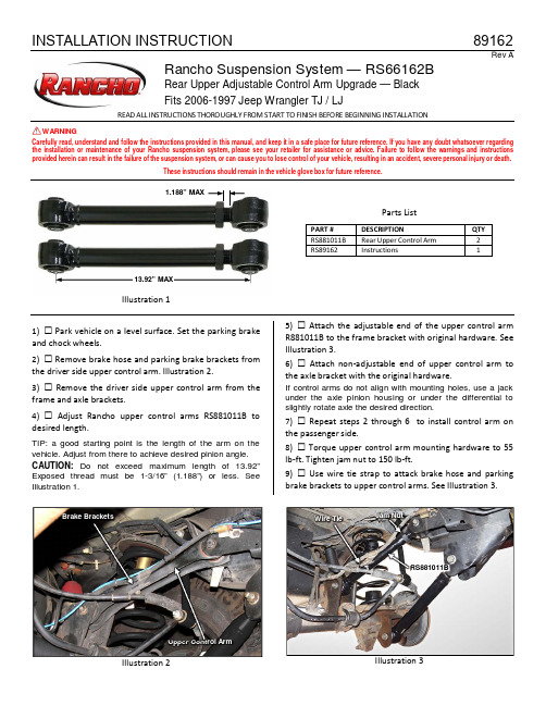
INSTALLATION INSTRUCTION89162Rev ARancho Suspension System — RS66162BRear Upper Adjustable Control Arm Upgrade — Black Fits 2006-1997 Jeep Wrangler TJ / LJREAD ALL INSTRUCTIONS THOROUGHLY FROM START TO FINISH BEFORE BEGINNING INSTALLATIONWARNINGCarefully read, understand and follow the instructions provided in this manual, and keep it in a safe place for future reference. If you have any doubt whatsoever regarding the installation or maintenance of your Rancho suspension system, please see your retailer for assistance or advice. Failure to follow the warnings and instructions provided herein can result in the failure of the suspension system, or can cause you to lose control of your vehicle, resulting in an accident, severe personal injury or death.These instructions should remain in the vehicle glove box for future reference.Illustration 1Parts ListPART # DESCRIPTIONQTY RS881011B Rear Upper Control Arm 2 RS89162Instructions11) Park vehicle on a level surface. Set the parking brake and chock wheels.2) Remove brake hose and parking brake brackets from the driver side upper control arm. Illustration 2.3) Remove the driver side upper control arm from the frame and axle brackets.4) Adjust Rancho upper control arms RS881011B to desired length.TIP: a good starting point is the length of the arm on the vehicle. Adjust from there to achieve desired pinion angle. CAUTION: Do not exceed maximum length of 13.92” Exposed thread must be 1-3/16” (1.188”) or less. See Illustration 1.5) Attach the adjustable end of the upper control arm R881011B to the frame bracket with original hardware. See Illustration 3.6) Attach non-adjustable end of upper control arm to the axle bracket with the original hardware.If control arms do not align with mounting holes, use a jack under theaxle pinion housing or under the differential toslightly rotate axle the desired direction.7) Repeat steps 2 through6 to install control arm on the passenger side.8) Torque upper control arm mounting hardware to 55 lb-ft. Tighten jam nut to 150 lb-ft.9) Use wire tie strap to attack brake hose and parking brake brackets to upper control arms. See Illustration 3.RS881011BJam Nut13.92” MAXWire TieUpper Control ArmBrake BracketsF INAL C HECKS & A DJUSTMENTS1) Turn the front wheels completely left then right. Verify adequate tire, wheel, brake hose and ABS wire clearance. Inspect steering and suspension for tightness and proper operation.2) With the suspension at maximum extension (full droop), inspect and rotate all axles and drive shafts. Check for binding and proper slip yoke insertion. The slip yoke should be inserted a minimum of one inch into the transfer case and/or transmission.3) Ensure that the vehicle brake system operates correctly. If new brake hoses were installed, verify that each hose allows for full suspension movement. 4) Readjust headlamps.5) Have vehicle Aligned to manufacturer’s specifications.Alignment Specifications Caster 7° ± 1.0°Camber (fixed angle) -0.25° ± 0.63° Toe-In (each wheel) 0.30° ± 0.15° Thrust Angle 0± 0.15°Torque SpecsFront ComponentsUpper Control Arm55 lb-ft Lower Control Arm Frame Mount 130 lb-ft Lower Control Arm Axle Mount 85 lb-ft Control Arm Jam Nuts 150 lb-ft Wheels (Lug Nuts)85-115 lb-ft.Rear ComponentsUpper Control Arm 55 lb-ft Lower Control Arm 130 lb-ft Control Arm Jam Nuts 150 lb-ft Wheels (Lug Nuts) 85-115 lb-ft.STANDARD BOLT TORQUE & IDENTIFICATIONINCH SYSTEMMETRIC SYSTEMBolt Size Grade 5 Grade 8 Bolt Size Class 8.8 Class 10.9 Class 12.95/16 15 LB-FT 20 LB-FT M6 5 LB-FT 9 LB-FT 12 LB-FT 3/8 30 LB-FT 35 LB-FT M8 18 LB-FT 23 LB-FT 27 LB-FT 7/16 45 LB-FT 60 LB-FT M10 32 LB-FT 45 LB-FT 50 LB-FT 1/2 65 LB-FT 90 LB-FT M12 55 LB-FT 75 LB-FT 90 LB-FT 9/16 95 LB-FT 130 LB-FT M14 85 LB-FT 120 LB-FT 145 LB-FT 5/8 135 LB-FT 175 LB-FT M16 130 LB-FT 165 LB-FT 210 LB-FT 3/4185 LB-FT280 LB-FT M18 170 LB-FT 240 LB-FT290 LB-FTRancho Technical Department 1-734-384-7804.WARNING: READ ALL INSTRUCTIONS THOROUGHLY FROM START TO FINISH BEFORE BEGINNING INSTALLATION. Failure to follow the warnings and instructions provided herein can result in an accident, severe personal injury or death.PRELIMINARYThis manual presumes that all persons installing this suspension system have a high level of mechanical training and experience, and have available to them all necessary tools and safety equipment. This manual is not and should not be construed as an exhaustive list of all required safety measures. Personnel should rely primarily on their training and experience, as well as on their own common sense.This Manual is to be read as a supplement to, and must not be construed as a substitute for, the owner’s manual and/or shop manual that originally accompanied the vehicle. Refer to such use, operation, maintenance and safety manuals as necessary, and especially after installation is complete, to insure proper vehicle operation.The following terminology has been used in this Manual: ACCIDENT: Any event which could cause personal injury or death to anyone installing or using the suspension system, aswell as to passengers and bystanders, or otherwise mayresult in property damage.PRE-INSTALLATION WARNINGS and INSTRUCTIONS WARNING: This suspension system will enhance the off-road performance of your vehicle. It will handle differently; both on and off-road, from a factory equipped passenger car or truck. Failure to drive this vehicle safely may result in serious injury or death to the driver and passengers. ALWAYS WEAR your seat belts, REDUCE your speed, and AVOID sharp turns and other abrupt maneuvers.Service and repair tasks require specialized knowledge, training, 1)tools, and experience. General mechanical aptitude may not be sufficient to properly install this suspension system. If you have any doubt whatsoever regarding your ability to properly install the suspension system, please consult a qualified mechanic.Your brake lines and fuel lines should remain undisturbed during 2)and after installation. If you think you need to modify these components in any way, you are mistaken. You are installing the lift improperly and will be creating a significant risk of an accident. In case of any doubt, consult a qualified mechanic.If any component does not fit properly, something is wrong. You 3)are installing the lift kit improperly and will be creating a significant risk of an accident. Never modify any component of the vehicle or suspension system, except as instructed herein. Do not continue with installation until you have identified the problem.Several of the procedures described herein require at least two 4)(2) persons to safely complete the task. If you have any doubt about your ability to complete any operation by yourself, always ask for help from a qualified assistant.Before starting any operation, confirm that all personal safety 5)devices and safety equipment are in proper condition and position. Give your work undivided attention. Looking around, carrying on a 6)conversation and "horse-play" are careless acts that can result in an error in installation and/or serious injury.Install only tires approved by the United States Department of 7)Transportation (“DOT approved”). Make sure the rim and tire size are properly matched.If any components of the vehicle or suspension system are 8)damaged in any way during installation, immediately replace the component.During installation, carefully inspect all parts of the vehicle and 9)replace anything that is worn or damaged.Nip points present the risk of the catching, lacerating, crushing 10)and/or amputating fingers, hands, limbs and other body parts during operations. Always keep clear. Wear protective gloves.Oil and hydraulic fluids are poisonous, dangerous to health and 11)are known to the State of California to cause cancer, birth defects or other reproductive harm. Do not inhale vapors or swallow. Do not allow contact with the eyes or skin. Should any oil or fluids be swallowed or inhaled or come into contact with the eyes, immediately follow the safety precautions on the label or call a poison control center immediately. Should any of the oil or fluids contact your skin, immediately wash thoroughly.Never install the suspension system if you are under the effects 12)of alcohol, medications and/or drugs. If you are taking prescription or over the counter medication, you must consult a medical professional regarding any side effects of the medication that could hinder your ability to work safely.AFTER INSTALLATION WARNINGS AND INSTRUCTIONS After installation is complete, drive the vehicle slowly in an area 13)free from heavy traffic for at least three (3) miles. Likewise, before traveling on any highways or at a high rate of speed, drive the vehicle for ten (10) miles on side roads at moderate speed. If you hear any strange noise or feel unusual vibration, if a component of the suspension system is not operating properly, or if any warning lights illuminate or buzzers sound, stop the vehicle immediately. Identify the cause and take any necessary remedial action.Confirm that all components of the vehicle, including all lights 14)(headlights, turn signals, brake lights, etc.), linkages (accelerator, etc.), electrical switches and controls (windshield wipers and defoggers, etc.), and other warning devices (low tire pressure monitoring systems) are fully operational.Your headlights will need to be readjusted before the vehicle is 15)used on the roads. Consult the vehicle owners’ manual.The speedometer and odometer will need to be recalibrated 16)after installation. See your dealer.Confirm proper rear view and side view while seated in the 17)driver seat. Install supplemental mirrors as necessary.Your original low tire pressure monitoring system may be re-18)installed in your new wheels. However, if you choose to purchase a new system, see your dealer to have them properly calibrated. Proper tire pressure is critical to safe operation of the vehicle. OPERATIONBecause it has been modified, the vehicle will not handle, turn, 19)accelerate or stop in the same manner as an unmodified vehicle. In addition, the crash protection systems designed in the vehicle may operate differently from an unmodified vehicle. For example, turning and evasive maneuvers must be executed at a slower rate of speed. Further, there is a greater risk that the vehicle could roll over. These differences could result in an increased possibility of an accident, personal injury or death. Learn the vehicle’s operations and handling characterizes and drive accordantly.IMPORTANT NOTESA.Before installing this system, have the vehicle’s alignmentand frame checked by a certified technician. The alignment must be within factory specifications and the frame of the vehicle must be sound (no cracks, damage or corrosion).Have all suspension, steering and driveline components inspected and replaced if worn or damagedB.The components of Rancho’s suspension system are designedas a single integrated system. To avoid compromises in terms of safety, performance, durability or function, do not install a body lift kit with Rancho’s suspension system or interchange parts from this system with components from another manufacturer. Use of other components will result in the forfeiture of any type of warranty on the vehicle/suspension system.C.Some components required for the installation of this kit mayneed to be purchased separately. See “SPECIFICATIONS & REQUIREMENTS” on next page of this manual.pare the contents of this system with the parts list inthese instructions. If any parts are missing, contact the Rancho Technical Department at 1-734-384-7804.E.Do not powder-coat or plate any of the components in thissystem. To change the appearance of components, automotive paint can be applied over the original coating. F.Each hardware kit in this system contains fasteners of highstrength and specific size. Do not mix hardware kits or substitute a fastener of lesser strength. See bolt identification table at end of instruction.G.Install all nuts and bolts with a flat washer. When both SAE(small OD) and USS (large OD) washers are used in a fastener assembly, place the USS washer against the slotted hole and the SAE washer against the round hole.H.Apply a drop of thread locking compound to all bolts duringinstallation. CAUTION: Thread locking compound may irritate sensitive skin. Read warning label on container before use.I.Unless otherwise specified, tighten all nuts and bolts to thestandard torque specifications shown in the table at end of instruction. USE A TORQUE WRENCH for accurate measurements.J.Do not weld anything to these components, and do not weld any of these components to the vehicle unless specifically stated in the instructions Welding on a vehicle creates an electrical charge throughout the body and frame. Disconnectthe vehicle’s battery prior to any welding. Place welding ground clamps as near as possible to the weld. Never use a vehicle suspension component as a welding ground point. K.It is extremely important to replace coil springs, axle flanges, and drive shaft/pinion relationships as original. Be sure to mark left/right, front/rear, and indexing of mating parts before disassembly. A paint marker or light colored nail polish is handy for this.L.Suspension components that use rubber or urethane bushings should be tightened with the vehicle at normal ride height unless otherwise specified. This will prevent premature failure of the bushing and maintain ride comfort. M.Some of the service procedures require the use of special tools designed for specific procedures. If you do not know how to safely use any of these tools, or do not have them, stop the project and consult a qualified mechanic. See “Tools and Supplies” on next page of this manualN.The required installation time for this system is approximately 2 hours for two people. Check off the box ( ) at the beginning of each step when you finish it. Then when you stop during the installation, it will be easier to find where you need to continue from.O.Important information for the end user is contained in the consumer/installer information pack. If you are installing this system for someone else, place the information pack on the driver’s seat. Please include the installation instructions when you finish.P.The lifespan of Rancho products depends on many factors.Improper use, abuse or harsh use in general may compromise the integrity of the suspension system and significantly reduce its lifespan. The suspension system is also subject to wear over time. Have the suspension system regularly inspected and maintained by qualified mechanics. If the inspection reveals any damage or excessive wear, no matter how slight, immediately replace or repair the component.The suspension system must be regularly maintained in order to optimize its safe and efficient use. The more severe the conditions under which the suspension system is operated, the more often it must be inspected and maintained.Q.If any component breaks or bends, contact your local Rancho dealer or Rancho for replacement parts or, contact the Rancho Technical Department at 1-734-384-7804.Thank you for purchasing the best suspension system available. For the best installed system, follow these instructions.If you do not have the tools or are unsure of your abilities, have this system installed by a certified technician.RANCHO IS NOT RESPONSIBLE FOR DAMAGE OR FAILURE RESULTING FROM AN IMPROPER INSTALLATIONThe driver of this suspension system recognizes and agrees that there are risks inherent in driving a vehicle with a lifted suspension system, including but not limited to the risk that you could be involved in an accident that would not occur in an unmodified vehicle. By his/her purchase and use of this suspension system, the user expressly, voluntarily and knowingly accepts and assumes these risks, and agrees to hold Tenneco, Inc. and its relatedcompanies harmless to the fullest extent permitted by law against any resulting damages.。
t6螺纹尺寸 -回复
t6螺纹尺寸-回复关于t6螺纹尺寸的这篇文章,我们将一步一步回答关于t6螺纹尺寸的问题,并对其进行详细解释。
一、什么是螺纹尺寸?螺纹尺寸是指螺纹的几何尺寸参数,包括直径、螺距、牙高等。
螺纹尺寸的准确度和精度对于螺纹连接的质量和性能至关重要。
二、什么是t6螺纹?t6螺纹是一种常见的螺纹类型,也叫作M6螺纹。
它是一种公制螺纹,主要用于机械设备和工程结构中的螺纹连接。
三、t6螺纹尺寸的具体参数是什么?根据国际标准ISO 68-1:1998,t6螺纹的具体参数如下:- 直径(D):6mm- 螺距(P):1mm- 牙高(h):2.64mm- 根径(d2):5.086mm- 外径(d3):6.000mm- 测量公差(H):0.13mm四、如何测量t6螺纹的尺寸?测量t6螺纹尺寸的最常用方法是使用螺纹卡尺或螺纹微量计。
具体步骤如下:1. 准备一个螺纹卡尺或螺纹微量计,确保其调节螺纹牙尖与螺纹牙谷的间距合适。
2. 将螺纹卡尺或螺纹微量计轻轻插入t6螺纹内,确保没有卡阻或卡紧。
3. 读取螺纹卡尺或螺纹微量计上的刻度值,即可得到t6螺纹的尺寸。
五、t6螺纹的应用领域是什么?由于t6螺纹的尺寸中等,适用性广泛,常被应用于各种机械设备和工程结构中的螺纹连接。
例如,汽车零部件、电子设备、家具等都可能使用t6螺纹。
六、t6螺纹的特点是什么?t6螺纹的特点包括以下几个方面:1. 易于安装和拆卸:采用常用的公制螺纹类型,安装和拆卸方便,适用于各种维修和更换场景。
2. 稳定的连接:t6螺纹能够提供较好的连接强度和稳定性,可以在工作环境中承受较大的力和扭矩。
3. 尺寸准确:t6螺纹采用了国际标准规定的尺寸参数,具有高度的准确度和精度。
4. 通用性强:由于t6螺纹是公制螺纹,因此具有较好的通用性,便于替代和替换。
通过以上内容,我们详细回答了关于t6螺纹尺寸的问题,并对其进行了解释和分析。
了解螺纹尺寸对于正确选择和使用螺纹连接具有重要意义,确保连接的质量和性能。
公差对照表-d11公差对照表

b c d e f g h js k m n p r s t u v x y z
间隙配合
过渡配合
过盈配合
H 6 H 6 H 6 H6 H6 H6 H6 H6 H6 H6 H6
f 5 g 5 h 5 js5 k5 m5 n5 p5 r5 s5 t5
H 6 H 7 H 7 H7 H7 H7 H7 H7 H7 H7 H7 H7 H7 H7 H7 H7
第九章 互换性与技术测量
第一节 第二节 第三节
表面粗糙度 公差与配合简介 形状和位置公差简介
.
§ 9--1 表面粗糙度
零件图中除了视图和尺寸之外,还应具备加工和检验零 件的技术要求。技术要求主要有: ➢ 零件的表面粗糙度。 ➢ 尺寸公差、形状公差和位置公差。 ➢ 对零件的材料、热处理和表面修饰的说明。 ➢ 对于特殊加工和检验的说明。
★ 同一表面上有不同表 面粗糙度要求时,应用细 实线分界,并注出尺寸与 表面粗糙度代号。
φ
RY2.5 RY2.5
0.8 6.3
.
§9—2 公差与配合简介
一、公差与配合的基本概念 1、零件的互换性
● 互换性: 同一批零件,不经挑选和辅助加工,任取一个就可
顺利地装到机器上去,并满足机器的性能要求。 ● 保证零件具有互换性的措施:
M
φ
φ 1.6
3.2
.
★ 在不同方向的
表面上标注时,代
3.2
号中的数字及符号
的方向必须按图中
的规定标注。
★ 代号中的数字
方向应与 尺寸数 字的方向 一致。
3.2
★ 符号的尖端必 须从材料 外指向 表面。
30° 3.2
3.2 3.2
30° 3.2
捷锐2012 HP价格表
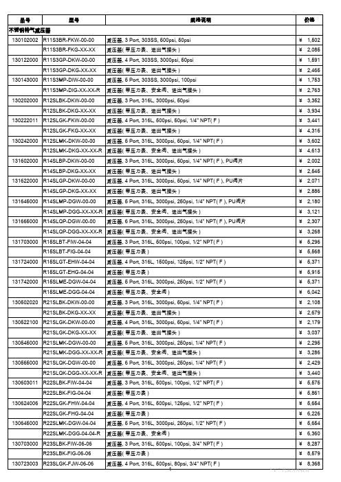
品号
型号
规格说明
价格
不锈钢特气减压器(接上页) R23SLGK-FJG-06-06 130745000 R23SLMK-DHW-06-06 R23SLMK-DHG-06-06-R 130845000 R31SLMK-DGW-00-00 R31SLMK-DGG-XX-XX 130865004 R31SLQK-DGW-00-00 减压器( 带压力表 ) 减压器, 5 Port, 316L, 3000psi, 125psi, 3/4" NPT( F ) 减压器( 带压力表、安全阀 ) 双级式减压器, 5 Port, 316L, 3000psi, 250psi, 1/4" NPT( F ) 双级式减压器( 带压力表、进出气接头 ) 双级式减压器, 6 Port, 316L, 3000psi, 250psi, 1/4" NPT( F ) ¥ 8,951 ¥ 8,513 ¥ 9,234 ¥ 4,937 ¥ 5,947 ¥ 5,082 ¥ 6,092 ¥ 1,000 ¥ ¥ 500 120
减压器, 3 Port, 303SS, 500psi, 50psi 减压器( 带压力表、进出气接头 ) 减压器, 4 Port, 303SS, 3000psi, 50psi 减压器( 带压力表、进出气接头 ) 减压器, 5 Port, 303SS, 3000psi, 100psi 减压器( 带压力表、安全阀、进出气接头 ) 减压器, 3 Port, 316L, 3000psi, 50psi 减压器( 带压力表、进出气接头 ) 减压器, 4 Port, 316L, 500psi, 50psi, 1/4" NPT( F ) 减压器( 带压力表、进出气接头 ) 减压器, 5 Port, 316L, 3000psi, 50psi, 1/4" NPT( F )
第02章 港口起重机的工作级别
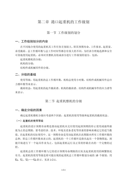
(1-2-4)
算得此载荷谱系数的计算值后,即可按表 1-2-6 确定该机构相应的载荷状态。
二、机构的工作级别
各机构单独作为一个整体进行分级。根据机构的使用等级和载荷状态,机构的工作 级别可分为 M1~M8 共 8 级,见表 1-2-7。 表 1-2-7 机构的工作级别
载 状 荷 态 使 T0 M1 M1 M1 M2 T1 M1 M1 M2 M3 T2 M1 M2 M3 M4 T3 M2 M3 M4 M5 用 T4 M3 M4 M5 M6 等 级 T5 T6 M4 M5 M5 M6 M7 M6 M7 M8 T7 M6 M7 M8 M8 T8 M7 M8 M8 M8 T9 M8 M8 M8 M8
CT ——起重机总的工作循环数, CT = ∑ C i = C1 + C 2 + C 3 "" + C n ;
i =1 n
1-2-2
m ——指数。为便于组别的划分,取 m =3。
展开后,(1-2-1)式变为:
KP =
C P C P C1 P C P ( 1 )3 + 2 ( 2 )3 + 3 ( 3 )3 "" + i ( n )3 CT Pmax CT Pmax CT Pmax CT Pmax
二、起重机整机的工作级别
根据起重机的使用等级和载荷状态,起重机整机的工作级别划分为 A1~A8 共 8 个 级别,见表 1-2-3。 表 1-2-3 起重机整机工作级别
荷 状 重 态 使 U0 A1 A1 A1 A2 U1 A1 A1 A2 A3 U2 A1 A2 A3 A4 U3 A2 A3 A4 A5 用 U4 A3 A4 A5 A6 等 级 U5 U6 A4 A5 A6 A7 A5 A6 A7 A8 U7 A6 A7 A8 A8 U8 A7 A8 A8 A8 U9 A8 A8 A8 A8
- 1、下载文档前请自行甄别文档内容的完整性,平台不提供额外的编辑、内容补充、找答案等附加服务。
- 2、"仅部分预览"的文档,不可在线预览部分如存在完整性等问题,可反馈申请退款(可完整预览的文档不适用该条件!)。
- 3、如文档侵犯您的权益,请联系客服反馈,我们会尽快为您处理(人工客服工作时间:9:00-18:30)。
2012年6月中国制造业采购经理指数为50.2%
来源:中国统计信息网2012-07-01 09:00:00
国家统计局服务业调查中心中国物流与采购联合会
2012年6月,中国制造业采购经理指数(PMI)为50.2%,比上月回落0.2个百分点。
分企业规模看,大型企业PMI为50.6%,比上月回落0.5个百分点,继续位于临界点以上;中型企业PMI为50.0%,位于临界点;小型企业PMI为47.2%,连续3个月位于临界点以下。
2012年6月,构成制造业PMI的5个分类指数2升3落。
生产指数为52.0%,比上月回落0.9个百分点,表明制造业企业生产增速继续放缓。
从行业情况看,纺织服装服饰业、电气机械器材制造业、铁路船舶航空航天运输设备制造业、食品及酒饮料精制茶制造业、烟草制品业等行业生产指数位于60%以上高位,生产量明显增长;石油加工及炼焦业、化学纤维及橡胶塑料制品业、汽车制造业、专用设备制造业、纺织业、非金属矿物制品业等行业生产指数位于临界点以下,生产量与上月相比均有所下滑。
新订单指数为49.2%,比上月下降0.6个百分点,连续2个月低于临界点,表明制造业市场需求继续回落。
从行业情况看,食品及酒饮料精制茶制造业、金属制品业、烟草制品业、电气机械器材制造业、纺织服装服饰业等行业企业新订单量保持稳步增长;纺织业、石油加工及炼焦业、化学原料和化学制品制造业、汽车制造业、化学纤维及橡胶塑料制品业等行业市场需求低迷,企业订单显著减少。
调查结果显示,反映制造业外贸情况的新出口订单指数为47.5%,降至临界点以下,比上月下降2.9个百分点,为2011年12月以来的最大降幅;进口指数为46.5%,比上月下降1.6个百分点,连续2个月位于临界点以下,表明本月制造业来自国外的产品订货和原材料进口量与上月相比均有所减少。
原材料库存指数为48.2%,比上月回升3.1个百分点,但仍位于临界点以下,表明制造业原材料库存量继续减少。
从行业情况看,石油加工及炼焦业、铁路船舶航空航天运输设备制造业、烟草制品业等行业原材料库存指数显著上升,由临界点以下跃至50%以上,原材料库存量大幅增加;纺织业、汽车制造业、专用设备制造业、有色金属冶炼及压延加工业、木材加工及家具制造业等行业原材料库存指数均连续位于临界点以下。
从业人员指数为49.7%,比上月下降0.8个百分点,落至临界点以下,表明制造业企业用工量与上月相比有所减少。
从行业情况看,铁路船舶航空航天运输设备制造业、化学原料和化学制品制造业、非金属矿物制品业、纺织服装服饰业、造纸印刷及文教体美娱用品制造业等行业劳动力需求增长;汽车制造业、专用设备制造业、通用设备制造业、纺织业等行业劳动力需求比上月减少。
供应商配送时间指数为49.1%,比上月回升0.1个百分点,仍位于临界点以下。
调查结果显示,主要原材料购进价格指数为41.2%,比上月大幅下降3.6个百分点,该指数已连续2个月位于临界点以下,表明制造业主要原材料购进价格呈明显回落态势。
从行业情况看,仅烟草制品业主要原材料购进价格有所上涨;农副食品加工业、木材加工及家具制造业等行业原材料购进价格指数为50.0%,企业采购成本与上月相比变化不大;其他制造业行业原材料购进价格与上月相比均有不同程度回落。
另外,本月产成品库存指数为52.3%,比上月上升0.1个百分点,是近7个月以来的新高,表明制造业企业产成品库存压力继续加大。
中国制造业PMI分类指数(经季节调整)
单位:%
PMI
生产新订单
原材料
库存从业人员
供应商配
送时间
2012年1月50.5 53.6 50.4 49.7 47.1 49.7
2012年2月51.0 53.8 51.0 48.8 49.5 50.3
2012年3月53.1 55.2 55.1 49.5 51.0 48.9
2012年4月53.3 57.2 54.5 48.5 51.0 49.6
2012年5月50.4 52.9 49.8 45.1 50.5 49.0
2012年6月50.2 52.0 49.2 48.2 49.7 49.1
附注
1.主要指标解释
采购经理指数(PMI),是通过对企业采购经理的月度调查结果统计汇总、编制而成的指数,它涵盖了企业采购、生产、流通等各个环节,是国际上通用的监测宏观经济走势的先行性指数之一,具有较强的预测、预警作用。
PMI通常以50%作为经济强弱的分界点,PMI 高于50%时,反映制造业经济扩张;低于50%,则反映制造业经济收缩。
2.调查范围
涉及《国民经济行业分类》(GB/T4754-2011)中制造业的31个行业大类,从全国抽取820家样本企业进行调查。
3.调查方法
制造业采购经理调查采用PPS(Probability Proportional to Size)抽样方法,以制造业行业大类为层,行业样本量按其增加值占全部制造业增加值的比重分配,层内样本使用与企业主营业务收入成比例的概率抽取样本。
本调查采用联网直报的调查方式对企业采购经理进行月度问卷调查。
4.计算方法
制造业采购经理调查问卷涉及生产量、新订单、出口订货、现有订货、产成品库存、采购量、进口、购进价格、原材料库存、从业人员、供应商配送时间等11个问题。
对每个问题分别计算扩散指数,即正向回答的企业个数百分比加上回答不变的百分比的一半。
PMI是一个综合指数,由5个扩散指数(分类指数)加权计算而成。
5个分类指数及其权数是依据其对经济的先行影响程度确定的。
具体包括:新订单指数,权数为30%;生产指数,权数为25%;从业人员指数,权数为20%;供应商配送时间指数,权数为15%;原材料库存指数,权数为10%。
其中,供应商配送时间指数为逆指数,在合成PMI综合指数时进行反向运算。
5.季节调整
采购经理调查是一项月度调查,受季节因素影响,数据波动较大。
现发布的PMI综合指数和各分类指数均为经季节调整后的数据。
