ATS022_Manual
施耐德ATS22软启动器用户手册[1]
![施耐德ATS22软启动器用户手册[1]](https://img.taocdn.com/s3/m/d3d26d772a160b4e767f5acfa1c7aa00b52a9d99.png)
施耐德ATS22软启动器用户手册========================一、产品简介------------施耐德ATS22软启动器是一种用于控制三相异步电动机启动和停止的设备,它可以根据设定的参数,对电动机的电压进行平滑调节,从而实现电动机的柔和启动和停止,减少电网冲击和机械应力,提高设备的可靠性和寿命。
适用于额定功率为3至315千瓦的三相异步电动机。
内置了多种保护功能,如过载、过热、过流、短路、缺相、欠压、过压等。
支持多种控制方式,如本地控制、远程控制、串口通讯等。
支持多种工作模式,如标准模式、泵模式、扭矩控制模式等。
具有故障诊断功能,可以记录最近的四次故障信息,并提供故障代码和解决方法。
二、产品安装------------选择合适的安装位置,确保软启动器周围有足够的空间进行散热和维护。
按照软启动器的型号和电动机的额定电流,选择合适的电缆和接线方式。
按照软启动器上的接线图,将电源线、电动机线、控制线等正确地连接到软启动器上。
检查接线是否正确无误,无短路或接地故障。
通电后,检查软启动器上的显示屏是否正常工作,无故障提示。
三、产品参数------------ATS22软启动器有多种型号,其主要参数如下表所示:---型号 ---额定电流(A) ---额定功率(kW) ---尺寸(mm) -----------------------------------------------------------------ATS22D17S ---17 ---7.5 ---140x230x165 -------ATS22D32S ---32 ---15 ---140x230x165 -------ATS22D47S ---47 ---22 ---140x230x165 -------ATS22D62S ---62 ---30 ---140x230x165 -------ATS22D75S ---75 ---37 ---140x230x165 -------ATS22D88S ---88 ---45 ---140x230x165 -------ATS22C11S ---110 ---55 ---210x300x200 -------ATS22C14S ---140 ---75 ---210x300x200 -------ATS22C17S ---170 ---90 ---210x300x200 -------ATS22C21S ---210 ---110 ---210x300x200 -------ATS22C25S ---250 ---132 ---210x300x200 -------ATS22C32S ---320 ---160 ---210x300x200 -------ATS22C41S ---410 ---200 ---210x300x200 -------ATS22C48S ---480 ---250 ---210x300x200 -------ATS22C59S ---590 ---315 ---210x300x200 ----四、产品操作------------参数设置:通过液晶显示屏和按键,可以对软启动器的各种参数进行设置,如启动电压、启动时间、停止时间、工作模式、保护功能等。
施耐德atsD型控制器用户手册
D型控制器用户手册施耐德万高(天津)电气设备有限公司SchneiderWingoal(Tianjin)ElectricEquipmentCo.,Ltd 尊敬的客户:谢谢您使用本公司生产自动转换开关电器(以下简称开关),为了您的安全和正确使用本产品,敬请您在安装、电路连接、运行、维护检查前,熟读本手册。
本手册仅适用于带D型控制器的开关下面的符号将用于本手册的说明,提醒您注意潜在的危险,或者请您注意那些阐述、简化过程和关键操作。
身安全危险或本开关的不可恢复性损坏。
:关键性操作,提示您使用不当时,可能使控制器工作于非正常状态。
:提供另外的信息或简化的操作方法。
请注意:电气设备应该让有资格的专业人员进行安装、操作、使用、维护。
未按使用手册操作而造成的不良后果,施耐德电气公司将不负任何责任。
控制器功能介绍本控制器工作电压为AC380V,工作频率为50Hz,主要功能是进行电压采集,根据电压的实时值进行故障判断(三相断相、欠压、过压和失压),并控制转换开关进行相应的转换动作。
用户还可根据实际需要选配电流模块实现实时电流、有功功率和有功电能的显示。
另外,控制器提供多组无源节点的输入和输出,包括故障输出、负荷卸载、发电机启动、动作无源输出、远程投备(无源输入)、消防联动(无源输入)以及通讯接口,具体接线参见第节。
控制器安装及接线说明1.1.控制器外形尺寸图1D型控制器外形尺1.2.控制器二次接线1.2.1.控制器端子说明1.2.2.A1-A3备A4-D2,A5-RJ,A6-OUT,A7-D3,A8-D1,A9-NJ,A10-12,主☐动作输出:当机构中电机转动时,常开触点闭合;☐故障输出:当常用或备用电源故障时,常开触点闭合;☐负荷卸载:在电网-发电机模式下,常用电源故障,常开触点闭合;☐发电机启动:在电网-发电机模式下,常用电源正常,常开触点闭合,常用电源故障,常开触点打开;☐RS485:通信用端口,A’B’为通信预留端口;☐IA~IC:电流互感器输入端口I*为输入端,I为输出端;(输入额定电流5A)☐远程投备(无源):短接此两点,机构转到备用位置,开关状态主分备合;(可靠距离10m)☐消防联动(无源):短接此两点,机构转到双分位置,开关状态主分备分;(可靠距离10m,WTS-D800~5000系列不具备该项功能):控制器的发电机启动端子在常用电源正常时常闭触点断开,当常用电源故障时常闭触点闭合以接通发电机启动电路;常开触点与之相反,请用户注意。
艾特邦22型号电源分布单说明书

Eaton ESWB22Eaton Switched Rack PDU, 0U, 36U, Inputs C20, 3.84 kW max, 16A, 200-240V, Outlets 20XC13 : 4XC19General specificationsEaton Switched Rack PDU ESWB2235533406960461604 mm52 mm 53 mm2.46 kg 2 yearRoHS Compliant EAC CE Marked IEC 60950-1IEC 61000-6-2IEC 61000-6-4EPDU SW 0U (C20 16A1P)20XC13:4XC19Product Name Catalog NumberEAN Product Length/DepthProduct Height Product WidthProduct Weight WarrantyCompliances CertificationsModel Code20Single-phaseConnecting cord with plugMetric3.84 kW max0U (Vertical)Vertical16AC20Ampere Meter Mounting material Display50/60 HzAt distance0° to 60°C (32° to 140°F)Eaton UPS and battery servicesEaton UPS Services Quick Guide 2021Eaton ePDU G3 - BrochureESWB22 sk-43419-y1Eaton ePDU G3 - Installation and Connectivity Quick StartNumber of Outputs C13PhaseElectrical connectionMounting dimension (standardized) WattageForm factorMounting directionAmperage RatingPackage contentsInput connectionFitted with:Frequency ratingEvaluationOperating Temperature BrochuresDrawingsManuals and user guidesRack PDUMounting accessories Network cable Configuration cable Splitter for daisy-chaining Quickstart guideSafety InstructionsEthernet interfaceYesNumber of outlets with earth pin24Mass configurationYesCommunicationHTTP, HTTPS, SSL, Telnet, FTP, SNMP, SMTP, DNS, DHCP, LDAP, RADIUSSpecial featuresRemote Site ManagementTurn off unused outlets tocontrol commissioningPhase Metering, CircuitBreaker Current Meteringand Input MeteringCircuit Breaker StatusMonitoringOutlet and IT EquipmentSwitching/reboot/sequencing across A and Bfeed in Daisy-ChainSequence Outlets to avoidin-rush current, to ensureequipment starts in correctorderHot-Swap Control modulewith advanced LCDOptionalTemperature/HumiditysensorBuilt-in IEC outlet eGripretention, retains allstandard IEC plugsDaisy-Chain up to 8 PDUs,reduce networkinfratsructure costsPower chain monitoring &Real time Intelligence onyour Data Center, via EatonIntelligent Power ManagerNumber of Outputs C194Outlet controlEaton Corporation plcEaton House30 Pembroke RoadDublin 4, Ireland © 2023 Eaton. All rights reserved. Eaton is a registered trademark.All other trademarks areproperty of their respectiveowners./socialmedia YesYes3m200-240VBlackYesAluminium2(20) C13, (4) C19Rack PDUYes52SwitchableCord lengthInput voltageColorSNMPMaterialOver voltage categoryOutletsTypeSerial interfaceMounting Dimension (metrical)。
Schneider Electric ATS01N212RT软启动器数据手册说明书

T h e i n f o r m a t i o n p r o v i d e d i n t h i s d o c u m e n t a t i o n c o n t a i n s g e n e r a l d e s c r i p t i o n s a n d /o r t e c h n i c a l c h a r a c t e r i s t i c s o f t h e p e r f o r m a n c e o f t h e p r o d u c t s c o n t a i n e d h e r e i n .T h i s d o c u m e n t a t i o n i s n o t i n t e n d e d a s a s u b s t i t u t e f o r a n d i s n o t t o b e u s e d f o r d e t e r m i n i n g s u i t a b i l i t y o r r e l i a b i l i t y o f t h e s e p r o d u c t s f o r s p e c i f i c u s e r a p p l i c a t i o n s .I t i s t h e d u t y o f a n y s u c h u s e r o r i n t e g r a t o r t o p e r f o r m t h e a p p r o p r i a t e a n d c o m p l e t e r i s k a n a l y s i s , e v a l u a t i o n a n d t e s t i n g o f t h e p r o d u c t s w i t h r e s p e c t t o t h e r e l e v a n t s p e c i f i c a p p l i c a t i o n o r u s e t h e r e o f .N e i t h e r S c h n e i d e r E l e c t r i c I n d u s t r i e s S A S n o r a n y o f i t s a f f i l i a t e s o r s u b s i d i a r i e s s h a l l b e r e s p o n s i b l e o r l i a b l e f o r m i s u s e o f t h e i n f o r m a t i o n c o n t a i n e d h e r e i n .Product data sheetCharacteristicsATS01N212RTsoft starter for asynchronous motor - ATS01 -12 A - 460..480 VProduct availability: Stock - Normally stocked in distribution facilityMainRange of product Altistart 01Product or component typeSoft starterProduct destination Asynchronous motors Product specific applica-tionSimple machine Device short name ATS01Phase3 phase[Us] rated supply volt-age460...480 V - 10...10 %Maximum Horse Power Rating7.5 hp, 3 phase 460...480 V IcL starter rating 12 AUtilisation category AC-53B EN/IEC 60947-4-2Current consumption 60 A at nominal load Type of startStart with voltage rampPower dissipation in W4 W at full load and at end of starting 124 W in transient stateComplementaryAssembly style With heat sink Function available Integrated bypass Supply voltage limits 414…528 V Supply frequency 50...60 Hz - 5...5 %Network frequency 47.5...63 HzOutput voltage<= power supply voltage [Uc] control circuit voltage Built into the starter Starting timeAdjustable from 1 to 10 s Deceleration time symb Adjustable from 1 to 10 sStarting torque 30...80 % of starting torque of motor connected directly on the line supply Discrete input type Logic LI1, LI2, BOOST) stop, run and boost on start-up functions <= 8 mA 27kOhm Discrete input voltage 24...40 VDiscrete input logic Positive LI1, LI2, BOOST < 5 V <= 0.2 mA > 13 V, >= 0.5 mA Discrete output current 2 A DC-133 A AC-15Discrete output type Open collector logic LO1 end of starting signal Relay outputs R1A, R1C NO Discrete output voltage 24 V 6...30 V) open collector logic Minimum switching current 10 mA 6 V DC relay outputsMaximum switching current Relay outputs 2 A 250 V AC cos phi = 0.5 20 ms inductive Relay outputs 2 A 30 V DC cos phi = 0.5 20 ms inductive Display type 1 LED green)starter powered up1 LED yellow)nominal voltage reached Tightening torque16.82…22.13 Lbf.In (1.9…2.5 N.m)4.43 lbf.in (0.5 N.m)Electrical connection 4 mm screw clamp terminal - rigid 1 1...10 mm² AWG 8 power circuitScrew connector - rigid 1 0.5...2.5 mm² AWG 14 control circuit4 mm screw clamp terminal - rigid 2 1...6 mm² AWG 10 power circuitScrew connector - rigid 2 0.5...1 mm² AWG 17 control circuitScrew connector - flexible with cable end 1 0.5...1.5 mm² AWG 16 control circuit4 mm screw clamp terminal - flexible without cable end 1 1.5...10 mm² AWG 8power circuitScrew connector - flexible without cable end 1 0.5...2.5 mm² AWG 14 control cir-cuit4 mm screw clamp terminal - flexible with cable end 2 1...6 mm² AWG 10 powercircuit4 mm screw clamp terminal - flexible without cable end 2 1.5...6 mm² AWG 10power circuitScrew connector - flexible without cable end 2 0.5...1.5 mm² AWG 16 control cir-cuitMarking CEOperating position Vertical +/- 10 degreeHeight 4.88 in (124 mm)Width 1.77 in (45 mm)Depth 5.16 in (131 mm)Net weight0.93 lb(US) (0.42 kg)Compatibility code ATS01N2EnvironmentElectromagnetic compatibility Conducted and radiated emissions level B CISPR 11Conducted and radiated emissions level B IEC 60947-4-2Damped oscillating waves level 3 IEC 61000-4-12Electrostatic discharge level 3 IEC 61000-4-2EMC immunity EN 50082-1EMC immunity EN 50082-2Harmonics IEC 1000-3-2Harmonics IEC 1000-3-4Immunity to conducted interference caused by radio-electrical fields level 3 IEC61000-4-6Immunity to electrical transients level 4 IEC 61000-4-4Immunity to radiated radio-electrical interference level 3 IEC 61000-4-3Micro-cuts and voltage fluctuation IEC 61000-4-11Voltage/current impulse level 3 IEC 61000-4-5Standards EN/IEC 60947-4-2Product certifications ULB44.1-96/ASME A17.5 for starter wired to the motor delta terminalCSACCCC-TickGOSTIP degree of protection IP20Pollution degree 2 EN/IEC 60947-4-2Vibration resistance 1 gn 13…150 Hz)EN/IEC 60068-2-61.5 mm peak to peak 3…13 Hz)EN/IEC 60068-2-6Shock resistance15 gn 11 ms EN/IEC 60068-2-27Relative humidity5…95 % without condensation or dripping water EN/IEC 60068-2-3Ambient air temperature for operation14…104 °F (-10…40 °C) without)104…122 °F (40…50 °C) with current derating of 2 % per °C)Ambient air temperature for storage-13…158 °F (-25…70 °C) EN/IEC 60947-4-2Operating altitude<= 3280.84 ft (1000 m) without> 3280.84 ft (1000 m) with current derating of 2.2 % per additional 100 m Ordering and shipping detailsCategory22392 - ATSU01/ATS01 LOW HP SOFT STARTERSDiscount Schedule I11GTIN00785901588337Package weight(Lbs)0.50 kg (1.11 lb(US))Returnability YesCountry of origin DEOffer SustainabilityREACh Regulation REACh DeclarationREACh free of SVHC YesEU RoHS Directive Pro-active compliance (Product out of EU RoHS legal scope)EU RoHS Decla-rationToxic heavy metal free YesMercury free YesRoHS exemption information YesChina RoHS Regulation China RoHS DeclarationCircularity Profile End Of Life InformationWEEE The product must be disposed on European Union markets following specificwaste collection and never end up in rubbish bins.Contractual warrantyWarranty18 monthsDimensions DrawingsDimensionsMounting on Symetrical (35 mm) RailScrew Fixing(1)Retractable fixingsConnections and Schema Example of Manual ControlA1 :Soft start/soft stop unit(1)For type 2 coordinationQ1 :Motor circuit-breakerF3 : 3 fast-acting fusesTechnical DescriptionFunction Diagram2-wire Control with DecelerationUs :Power supply voltageGreen LEDLED1 :LI2 :Logic inputR1 :Relay outputLO1 :Logic outputLEDYellow LED2 :3-wire Control with DecelerationUs :Power supply voltageGreen LEDLED1 :Logic inputsLI2,LI1 :R1 :Relay outputLO1 :Logic outputUm :Motor voltageLEDYellow LED2 :。
ATS22快速入门
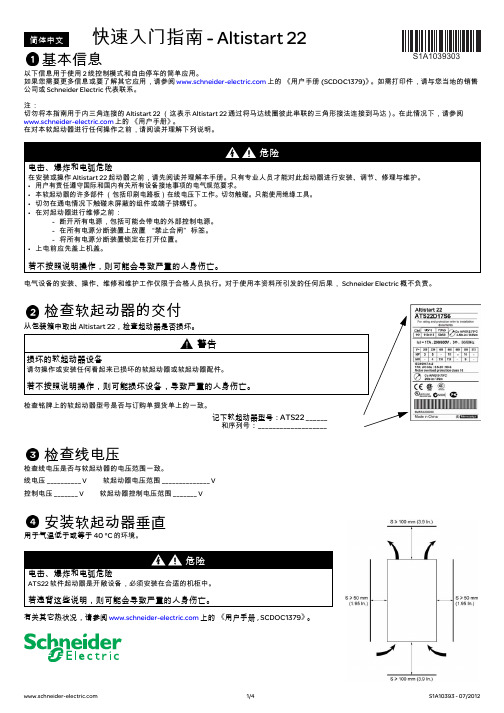
有关其它热状况,请参阅 上的 《用户手册 , SCDOC1379》。
1/4
S1A10393 - 07/2012
连接软起动器
⁄„ı⁄
1L1 3L2 5L3
检查软起动器的交付
从包装箱中取出 Altistart 22,检查起动器是否损坏。
警告
损坏的软起动器设备
请勿操作或安装任何看起来已损坏的软起动器或软起动器配件。
若不按照说明操作,则可能损坏设备,导致严重的人身伤亡。
检查铭牌上的软起动器型号是否与订购单提货单上的一致。
记下软起动器型号:ATS22 ______ 和序列号:___________________
调整 UIn 线电压
• 按 按钮,至 conF 菜单。 • 按 按钮。 • 按 按钮,至 UIn 参数。 • 利用向上滚动或向下滚动按钮,将 UIn 设置为电源电压交流值。 • 按 按钮以验证 UIn 值。
给 Altistart 22 通电并启动电机
• 盖上机盖。 • 按 S2 按钮。 • 软起动器显示 rdY。 • 闭合 S3,电机启动。
适用于 ATS22pppQ 或 ATS22pppS6 2 线控制,自由停车
Rdy Com Run Trip
a) 连接电源回路:
- 将软起动器接地。 - 将软起动器连接到线电源:1/L1 – 3/L2 – 5/L3。 - 检查电机电压是否与软起动器电压一致。 - 将软起动器连接到电机。
2T1 4T2 6T3 ⁄„ı⁄
U1 V1 W1
Motor
M1 3
(1) 检查触点的操作限制。 (2) 根据电源电压选择变压器。
b) 连接控制回路:
ATS021,ATS022选配表2011_Add T7

CNILG CODE
2TFF100012R1001 2TFF100013R1001 见T4,T5 LIST 1SDA054897R1 1SDA054910R1 1SDA054946R1 1SDA054948R1 1SDA054951R1 1SDA054949R1 -
6 7 8
安装板 MCB 接触器
1 2 2
适用
通用 通用 T4/T5通用 T4/T5/T6通用 T4/T5通用 T4+T4 T5+T5 T4+T5
通用
型号描述
ATS021 ATS022 见T6 LIST MOE 220-250Vac/dc T6 MOE-E 220-250Vac/dc T6 AUX-C 1Q1SY-Cabled 250Vac/dc T6 MIR-HB S264-C10 A 9-30-01-220V
数量
1 2 2 1 2 2 2
MM#
10100413 10100414
CNILX CODE
2TFF100012R1001 2TFF100013R1001 见T7M LIST -
10104186
10012375 10050881
1SDA062104R3 1SDA062127R1 1SDA062129R1 -
ATS021/022 产品选配表(T4,T5)
NO.
1 2 3 4 5
PART
智能控制器 MCCB 电动操作机构 辅助触点 机械联锁
数量
1 2 2 2 1
MM#
10100413 10100414 10065033 10064993 10099715 10099716 10099717 10099718 10012375 10050881
ATS22 Soft Start-Soft Stop Unit User Manual

B B V 51330 Altistart 22Soft start - soft stop unitUser manual01/2014The information provided in this documentation contains general descriptions and/or technical characteristics of the performance of the products contained herein. This documentation is not intended as a substitute for and is not to be used for determining suitability or reliability of these products for specific user applications. It is the duty of any such user or integrator to perform the appropriate and complete risk analysis, evaluation and testing of the products with respect to the relevant specific application or use thereof. Neither Schneider Electric nor any of its affiliates or subsidiaries shall be responsible or liable for misuse of the information contained herein. If you have any suggestions for improvements or amendments or have found errors in this publication, please notify us. No part of this document may be reproduced in any form or by any means, electronic or mechanical, including photocopying, without express written permission of Schneider Electric.All pertinent state, regional, and local safety regulations must be observed when installing and using this product. For reasons of safety and to help ensure compliance with documented system data, only the manufacturer should perform repairs to components. When devices are used for applications with technical safety requirements, the relevant instructions must be followed.Failure to use Schneider Electric software or approved software with our hardware products may result in injury, harm, or improper operating results.Failure to observe this information can result in injury or equipment damage.© 2013 Schneider Electric. All rights reserved.ContentImportant Information__________________________________________________________________________________________ 4Before you begin______________________________________________________________________________________________ 5Documentation structure________________________________________________________________________________________ 6Steps for setting up the soft starter (also refer to Quick Start guide)__________________________________________ 7 Receiving and handling________________________________________________________________________________________ 8Selection___________________________________________________________________________________________________ 10Dimensions and weights_______________________________________________________________________________________ 14Mounting___________________________________________________________________________________________________ 17Mounting - Fan option_________________________________________________________________________________________ 20Thermal protection___________________________________________________________________________________________ 22Wiring_____________________________________________________________________________________________________ 26Wiring - power terminals_______________________________________________________________________________________ 32Wiring - control terminals______________________________________________________________________________________ 35Wiring - in line connection - application diagram____________________________________________________________________ 38Display terminal_____________________________________________________________________________________________ 42Remote keypad display - option_________________________________________________________________________________ 44Programming_______________________________________________________________________________________________ 45List of parameters____________________________________________________________________________________________ 48Parameter settings___________________________________________________________________________________________ 49Configuration menu (ConF)____________________________________________________________________________________ 50Settings menu (SEt)__________________________________________________________________________________________ 51Advanced adjustments menu (AdJ)______________________________________________________________________________ 53Advanced settings menu (SEt2)_________________________________________________________________________________ 55Advanced protections menu (PrO)_______________________________________________________________________________ 56Advanced IO menu (IO)_______________________________________________________________________________________ 60Advanced communication menu (COP)___________________________________________________________________________ 62Advanced monitoring menu (SUP)_______________________________________________________________________________ 63Utility menu (UtIL)____________________________________________________________________________________________ 64Command channel___________________________________________________________________________________________ 65Modbus Function____________________________________________________________________________________________ 68Connection to RS485 bus______________________________________________________________________________________ 73Maintenance________________________________________________________________________________________________ 74Diagnostics / Troubleshooting__________________________________________________________________________________ 75Parameter Index and Modbus addresses__________________________________________________________________________ 77Annex 1: UL508 schematics____________________________________________________________________________________ 82Important InformationNOTICERead these instructions carefully, and look at the equipment to become familiar with the device before trying to install, operate, or maintain it. The following special messages may appear throughout this documentation or on the equipment to warn of potential hazards or to call attention to information that clarifies or simplifies a procedure.PLEASE NOTEElectrical equipment should be installed, operated, serviced, and maintained only by qualified personnel. No responsibility is assumed by Schneider Electric for any consequences arising out of the use of this product.© 2013 Schneider Electric. All Rights Reserved.NOTICENOTICE, used without the safety alert symbol, indicates a potentially hazardous situation which, if not avoided, can result in equipment damage.The addition of this symbol to a Danger or Warning safety label indicates that an electrical hazard exists, which will result in personal injury if the instructions are not followed.This is the safety alert symbol. It is used to alert you to potential personal injury hazards. Obey all safety messages that follow this symbol to avoid possible injury or death.Before you beginRead and understand these instructions before performing any procedure with this soft starter.(1)For additional information, refer to NEMA ICS 1.1 (latest edition), “Safety Guidelines for the Application, Installation, and Maintenanceof Solid State Control”.Documentation structureThe following Altistart 22 technical documents are available on the Schneider Electric website (). User manualThis manual describes how to install, commission, operate, and program the soft starter.Quick Start guideThis document (S1A10388) is delivered with the soft starter, and you can download it on . Quick Start annexAnnex for UL508 with SCCR (Short Circuit Current Ratings) and branch circuit protection).This document (S1A14738) is delivered with the soft starter, and you can download it on .Steps for setting up the soft starter (also refer to Quick Start guide)1. Receive and Inspect the soft starter vCheck that the soft starter reference on the nameplate is similar to thepurchase order.v Remove the Altistart 22 from packaging and check that it has not beendamaged2. Check the line voltage compatibility v Check that the line voltage, and control voltage arecompatible with the soft starter (pages 11 to 13).3. Mount the soft starter vertically v Mount the soft starter in accordance with theinstructions in this document (page 17).4. Wire the soft starter (page 29)v Connect the motor, ensuring that itsconnections correspond to the voltage.v Connect the line supply, after makingsure that the power is off.v Check and Connect the control supplyon CL1-CL25. Configure the soft starter(page 45)v Power on control, and do not givea start command.v Adjust UIn line voltage.v Adjust In motor rated current.6. StartSteps 1 to 4 areperformed withthe power off .IntroductionThe ATS22 offers acceleration and deceleration control of standard three-phase asynchronous induction (squirrel cage) motors. The ATS22controls the motor performance based on the motor torque rather than simple voltage or current based control. Advanced control algorithms are incorporated to help smooth rotation throughout the starting ramp and reducing mechanical instability at the end of starting.A digital keypad display is provided for soft starter setup and motor performance display.The ATS22 is available in 15 rated currents from 17 to 590A. ATS22 are rated for use from 208 to 600V motors, and are self-adjusting for a 50Hz or 60Hz supply frequency.This user manual covers the technical characteristics, specifications, installation, wiring, programming, and troubleshooting of ATS22.TerminologySome of the terms and acronyms used in this manual are defined in the table below:Receiving and Preliminary InspectionBefore installing the ATS22 soft starter, read this manual and follow all precautions.Before removing the ATS22 soft starter from its packing material, verify that the packing carton is not damaged from shipping. Damage to the packing carton usually indicates improper handling. If any damage is found, notify the carrier and your Schneider Electric representative.After removing the ATS22 soft starter from its packaging, inspect it for damage. If any shipping damage is found, notify the carrier and your sales representative. Verify that the ATS22 soft starter nameplate and label conform to the packing slip and corresponding purchase order.Storing and ShippingIf the ATS22 soft starter is not being immediately installed, store it in a clean, dry area where the ambient temperature is between -25 °C and +70 °C (-13 °F and +158 °F).If the ATS22 soft starter must be shipped to another location, use the original shipping material and carton to help protect it.Soft starter catalog numbersCatalog numbers are composed with:(1)The range is composed of 5 physical frame sizes distributed in 15 ratings from D17 to C59 (see page 11).TermDefinition Soft starter FLA Soft starter Full Load Amps This value is on the soft starter nameplate IcL.IcL : Soft starter rated currentMotor FLA Motor Full Load AmpsThis value is on the motor nameplate.The rated current of an induction motor at rated speed and load.Soft starter in line connection: In = rated current of the motor FLA.Soft starter inside delta connection: In = rated current of the motor FLA / 3.OCPDOvercurrent protective device. Soft starter rating (1)Power and control voltageProduct symbol 230-440V, 230Vac control supply, 24Vdc logic inputs 208-600V, 230Vac control supply, 24Vdc logic inputs 208-600V, 110Vac control supply, 110Vac logic inputsHandling the soft starterHoisting the ATS22The ATS22 range comprises 5 frame sizes, with various weights and dimensions.Small soft starters can be removed from their packaging and installed without a handling device. A handling device must be used from ATS22C21ppp to ATS22C59ppp; for this reason they are supplied with lifting holes.Do not remove the ATS22 from the carton until it is at the final installation site. Handlethe soft starter carefully after removing it from the carton to avoid damage to theinternal components, frame, or exterior. Once removed from the carton, the soft startercan be handled:•With a hoist. When hoisting the soft starter, attach a spreader bar to the twolifting holes on top as shown below.•In a horizontal position, with the back of the soft starter resting on a pallet.45°maxiPackage content•Soft starter•Quick Install guide•Package of screws for frame sizes C, D, and E•Allen key, supplied with size B productsSelectionSoft starter selectionS1 motor duty corresponds to starting followed by operation at constant load enabling the thermal stability to be reached.S4 motor duty corresponds to a cycle comprising starting, operation at constant load, and an idle period. This cycle is characterized by a load factor.The Altistart 22 must be selected depending on the type of application ("standard" or "severe") and the nominal power of the motor."Standard" or "severe" applications define the limiting values of the current and the cycle for motor duties S1 and S4. These duties are described in the IEC 60034-1.Standard applicationExample: centrifugal pumpIn standard application, the Altistart 22 is designed to provide:• in S1 duty: starting at 3.5 In for 40seconds from a cold state.• in S4 duty: a load factor of 90% and n starts per hour (see table below), with 3.5 In for 20seconds or an equivalent thermal cycle.In this case, the motor thermal protection must conform to protection class 10.:(1) Note: in case of both soft starts and soft stops, the number of starts has to be divided by 2.Severe applicationThe Altistart 22 rated current is limited to 3.5 IcL , see table page 19.IcL is the nominal current of the Altistart 22. If the application requires a higher rated starting current (> 3.5 IcL ), the soft starter must be oversized. See soft starter selection table, page 11.Soft starter sizing according to thermal protection class* Nominal = nominal size of the soft starter according to the nominal motor current (Motor FLA).** Nominal + 1 = oversize the soft starter by one rating compared to the nominal motor current (Motor FLA).*** Nominal + 2 = oversize the soft starter by 2 ratings compared to the nominal motor current (Motor FLA).FramesizeIn S4 duty, number ofstarts (1) per hourStandard With fanA 610B 610C 410D NA 4E NA 4Starting current Protection classClass 10Class 20Class 30y 3.5In max starting time Nominal*16s Nominal + 1**32s Nominal + 2*** 48ssoft starter in line connectionThe nominal motor current In must not exceed the maximum permanent current in class 10.See wiring page 30.Maximum surrounding temperatureThe information in the table above is based on operation at a maximum ambient temperature of 40 °C (104 °F) and mini. -10 °C (14 °F).The Altistart 22 can be used up to an ambient temperature of 60 °C (140 °F) as long as the max. permanent current in class 10 is derated by 2.2% for each degree above 40 °C (104 °F).Example: ATS22D32Q at 50 °C (122 °F) derated by 10 x 2.2% = 22%, 32A becomes 32 x (1-0.22) = 24.96A (max. nominal motor current).MotorAltistart 22ppp Q, 230/440 V (+ 10% - 15%) - 50/60 Hz (+/- 10%)Nominal motor power Motor nominal current In (Motor FLA)Soft starter rated current IcL (Soft starter FLA)Reference 230V 400V 440V kW kW kW A A 47.57.514.817ATS22D17Q 7.5151528.532ATS22D32Q 1122224247ATS22D47Q 1530305762ATS22D62Q 18.537376975ATS22D75Q 2245458188ATS22D88Q 305555100110ATS22C11Q 377575131140ATS22C14Q 459090162170ATS22C17Q 55110110195210ATS22C21Q 75132132233250ATS22C25Q 90160160285320ATS22C32Q 110220220388410ATS22C41Q 132250250437480ATS22C48Q 160315355560590ATS22C59Qsoft starter inside delta connectionOnly the Altistart 22ppp Q can be installed inside delta connection.(1)Line current is maximum 1.5 IcL . Also, the In setting must not exceed IcL .Example: for a 400V - 110kW motor with a line current of 195A, the minimum soft starter rated current,IcL = 195/1.5 = 130A. Thus select ATS22C14Q The nominal motor current In must not exceed the max. permanent current in class 10.See wiring page 26.Maximum surrounding temperatureThe information in the table above is based on operation at a maximum ambient temperature of 40 °C (104 °F) and mini. -10 °C (14 °F).The Altistart 22 can be used up to an ambient temperature of 60 °C (140 °F) as long as the max. permanent current in class 10 is derated by 2.2% for each degree above 40 °C (104 °F).Example: ATS22D32Q at 50 °C (122 °F) derated by 10 x 2.2% = 22%, 48A becomes 48 x 0.78 = 37.5A (max. nominal motor current).NOTICERISK OF DAMAGE TO THE MOTORATS22ppp S6 and ATS22ppp S6U must not be installed inside delta connection.Failure to follow these instructions can result in equipment damage.MotorSoft starter 230/440 V (+ 10% - 15%) - 50/60 Hz (+/- 10%)Nominal motor power Line current (Motor FLA) (1)In setting (Line current/3)Soft starter rated current IcL(soft starter FLA)Soft starterreference230V 400V 440V kW kW kW A A A 5.511152514.417ATS22D17Q 1122224827.732ATS22D32Q 18.545457040.447ATS22D47Q 2255559353.762ATS22D62Q 30557511264.775ATS22D75Q 37757513276.288ATS22D88Q 45909016595.3110ATS22C11Q 55110110210121.2140ATS22C14Q 15132132255147.2170ATS22C17Q 90160160315181.9210ATS22C21Q 110220220375216.5250ATS22C25Q 132250250480277.1320ATS22C32Q 160315355615355.1410ATS22C41Q 220355*********.7480ATS22C48Q 250400500885511.0590ATS22C59QStandard application, 208/600 V supply, soft starter in line connection(1)Value not indicated when there is no corresponding standardized motor.The nominal motor current In must not exceed the max. permanent current in class 10.Maximum surrounding temperatureThe information in the table above is based on operation at a maximum ambient temperature of 40 °C (104 °F) and mini. -10 °C (14 °F).The Altistart 22 can be used up to an ambient temperature of 60 °C (140 °F) as long as the max. permanent current in class 10 is derated by 2.2% for each degree above 40 °C (104 °F).Example: ATS22D32S6 at 50 °C (122 °F) derated by 10 x 2.2% = 22%, 27A becomes 27 x 0.78 =21.06A (max. nominal motor current).MotorSoft starter 208/600 V (+ 10% - 15%) 50/60 Hz (+/- 10%)Nominal motor power Motor nominal current In (Motor FLA)Soft starter rated current IcL (Soft starter FLA)Soft starter reference 208V 230V 230V400V 440V 460V 500V 575VHP HP kW kW kW HP kW HPA A 3547.57.5109151417ATS22D17S6 or S6U 7.5107.515152018.5252732ATS22D32S6 or S6U (1)151122223030404047ATS22D47S6 or S6U 15201530304037505262ATS22D62S6 or S6U 202518.537375045606575ATS22D75S6 or S6U 25302245456055757788ATS22D88S6 or S6U 3040305555757510096110ATS22C11S6 or S6U 405037757510090125124140ATS22C14S6 or S6U 5060459090125110150156170ATS22C17S6 or S6U 607555110110150132200180210ATS22C21S6 or S6U 7510075132132200160250240250ATS22C25S6 or S6U 10012590160160250220300302320ATS22C32S6 or S6U 125150110220220300250350361410ATS22C41S6 or S6U 150-(1)132250250350315400414480ATS22C48S6 or S6U (1)200160315355400400500477590ATS22C59S6 or S6UFor frame sizes D17 to D88, the fan is sold separately. (1)c: dimension of the product alone.c1: dimension of the product with its fan.(1) The voltage of the fan has to match the control voltage of the soft starter:ATS22ppp Q or ATS22ppp S6 Fan 230V (VW3G22ppp , ppp = 400 for size A, 401 for size B or 402 for size C)ATS22ppp S6U Fan 110V (VW3G22U ppp , ppp = 400 for size A, 401 for size B or 402 for size C)ATS22Framesizea b c c1e H Standard G With fanG1Dmm Weight mm (in.)mm (in.)mm (in.)mm (in.)mm (in.)mm (in.)mm (in.)mm (in.)mm (in.)kg (lb)D17A 130(5.1)265(10.4)169(6.6)209(8.2)6.5(0.3)250(9.8)100(3.9)65(2.6)7(0.28)5.5(12.1)D32A D47A D62B 145(5.7)295(11.6)207(8.1)247(9.7)10.5(0.4)276(10.9)115(4.5)80(3.15)7(0.28)7.8(17.2)D75B D88BFor frame sizes C11 to C17, the fan is sold separately. (1)c: dimension of the product alone.c1: dimension of the product with its fan.(1) The voltage of the fan has to match the control voltage of the soft starter:ATS22ppp Q or ATS22ppp S6 Fan 230V (VW3G22ppp , ppp = 400 for size A, 401 for size B or 402 for size C)ATS22ppp S6U Fan 110V (VW3G22U ppp , ppp = 400 for size A, 401 for size B or 402 for size C)ATS22Framesize Ca b c c1e H G1P Q Q1S D1D2D3Weight mm (in.)mm (in.)mm (in.)mm (in.)mm (in.)mm (in.)mm (in.)mm (in.)mm (in.)mm (in.)mm (in.)mm (in.)mm (in.)mm (in.)kg (lb)C11150(5.9)356(14)229.5(9)269.5(10.6)10.5(0.41)331(13)120(4.7)40.5(1.6)34.5(1.3)5(0.2)20(0.8)9(0.35)7(0.28)6(0.23)12.2(26.9)C14C17For frame sizes C21 to C59, the fan is integrated.ATS22Framesizea b c e H G1P Q Q1S D1D2Weightmm (in.)mm(in.)mm(in.)mm(in.)mm(in.)mm(in.)mm(in.)mm(in.)mm(in.)mm(in.)mm(in.)mm(in.)kg (lb)C21D206 (8.1)425(16.7)299(11.8)15(0.59)396(15.6)157(6.2)60(2.4)40(1.6)1.3(0.05)30(1.2)13.5(0.53)9(0.35)20.5(45.2)C25D C32D C41DC48E304(11.9)455(17.9)339.7(13.4)15(0.59)426(16.8)264(10.4)94(3.7)55(2.2)1(0.04)40(1.6)13.5(0.53)9(0.35)33(73.3)C59EMounting PrecautionsFollow these precautions when mounting the ATS22 soft starter:•The soft starter is compliant with pollution Degree 2 as defined in NEMA ICS1-1 or IEC 60664-1.•For environment pollution degree 3 install the product inside a cabinet type 12 or IP54.•The ATS22 soft starter generates heat and must be properly ventilated. Refer to "Thermal considerations for sizing enclosures” page 19 to determine power dissipated.•When several soft starters are installed in a control panel, arrange them in a row. Do not stack soft starters. Heat generated from the bottom soft starter can adversely affect the ambient temperature around the top soft starter.•Install the ATS22 vertically, within ± 10° (other positions are not allowed).•Do not place it close to heating elements. Leave sufficient free space so that the air required for cooling purposes can circulate from the bottom to the top of the unit.•Electrical current through the ATS22 will result in heat losses that must be dissipated into the ambient air immediately surrounding the soft starter. To help prevent a thermal fault, provide sufficient enclosure cooling and/or ventilation to limit the ambient temperature around the soft starter.S ≥ 100mm (3.9 in)S ≥ 50mm(1.95in.)S ≥ 50mm (1.95in.)Note: For the soft starters mounted side-by-side, the free space must be ≥ 50mm (1.95in.)S ≥ 100mm (3.9 in)Soft starter ventilationOn soft starters installed with a cooling fan, the fan is factory set to switch on automatically as soon as the heatsink temperature reaches 46 °C (114.8 °F).It is switched off when the heatsink temperature falls back to 43 °C (109.4 °F). This behavior can be modified by adjusting the FAn parameter in IO menu on page 61.Fan flow rates(1)Cubic Feet / MinuteMounting in a General Purpose Metal EnclosureObserve the mounting recommendations on the previous page.To help proper air circulation in the soft starter:•Install ventilation grilles.•Verify that ventilation is adequate: if not install a forced ventilation unit, with a filter if necessary.Derate the soft starter current IcL by 2.2% per °C for temperatures above 40 °C up to 60 °C (104 °F up to 140 °F).ReferenceFramesizeUnitStandard With optional fan kit 110V 230V 110V 230V ATS22 D17, D32, D47Am 3/hour--2831CFM (1)--1618ATS22 D62, D75, D88 B m 3/hour--2831CFM (1)--1618ATS22 C11, C14, C17C m 3/hour--108108CFM (1)--6464ATS22 C21, C25, C32, C41D m 3/hour148148--CFM (1)8787--ATS22 C48, C59E m 3/hour148148--CFM (1)8787--Mounting in a dust and damp-proof metal enclosureVentilation for dust and damp- proof enclosureFollow the instructions in this section in order to meet NEMA Type 12 (IP54) degree of protection.Do not use insulated or non-metallic enclosures as they have poor thermal conduction. Provide a stirring fan to circulate air inside the enclosure and to help prevent hot spots in the soft starter. This allows operation of the soft starter in an enclosure with a maximum internal temperature of 60 °C (140 °F). Ensure that the ambient temperature around the soft starters does not exceed this limit.Derate the soft starter current IcL by 2.2% per °C for temperatures above 40 °C up to 60 °C (104 °F up to 140 °F).Thermal considerations for sizing enclosuresWhen mounting the ATS22 soft starter in an enclosure, use the enclosure manufacturers’ recommendations for proper sizing based on thermal considerations. For this, it is necessary to sum the power dissipated by each device in the enclosure. Table hereafter lists the steady state and starting power dissipations for the ATS22 soft starter, operating at rated current.Power dissipated by the soft starters, at their nominal current(1)For ATS22ppp Q, ATS22ppp S6 and ATS22ppp S6U, frame sizes A, B and C the shorting contactor power is included in the electronics.(2)Optional fan kitθ°i = internal ambient temperature θ°e = external ambient temperatureSoft starter referencePowerControl supplyFrame sizeIcL During starting total power at 3.5 IcL Steady state total power bypass Electronics Shorting contactors (1)FansA W W W W W ATS22D17A 17208520-14 (2)ATS22D32A 3240410ATS22D47A 4756214ATS22D62B 627811920-20 (2)ATS22D75B 75101623ATS22D88B 88106026ATS22C11C 11013453320-20 (2)ATS22C14C 140154842ATS22C17C 170192251ATS22C21D 210259663201420ATS22C25D 250327575ATS22C32D 320369996ATS22C41D 4105147123ATS22C48E 4806396144201440ATS22C59E5907599177Example: for an ATS22D47Example: for an ATS22C48Power dissipated during starting: 562W Power dissipated in steady state: 14WPower for Control supply: 20W without fan, 34W with fanPower dissipated during starting: 6396W Power dissipated in steady state: 144W Power for Control supply: 74WMounting - Fan optionFan for frame sizes A, B and CConnections between the fan and the ATS22ATS22pppQ or ATS22ppp S6 Fan 230V ATS22ppp S6U Fan 110VTightening torque: 3.5N·m (31 lb.in)* As 2 different fan options could be connected to the ATS22according to the fan voltage (matching the ATS22 control voltage), the connector is different according to the voltage, to help avoid wrong assembly and misuse.(1) The voltage of the fan has to match the control voltage of the soft starter:Mounting - Fan optionFan dimensions for frame sizes ATS22D17 to C17For frame sizes D17 to D88, the fan is sold separately. (1)(1) The voltage of the fan has to match the control voltage of the soft starter.ATS22ppp Q or ATS22ppp S6 Fan 230V (VW3G22ppp , ppp = 400 for size A, 401 for size B or 402 for size C)ATS22ppp S6U Fan 110V (VW3G22U ppp , ppp = 400 for size A, 401 for size B or 402 for size C)Fan kitATS22a b k e H G G1X D Weight mm (in.)mm (in.)mm (in.)mm (in.)mm (in.)mm (in.)mm (in.)mm (in.)mm (in.)kg (lb)AD17130(5.1)265(10.4)40(1.6)8.5(0.33)248(9.8)100(3.9)65 (2.6)250 (9.8)7(0.28)1.2 (2.6)D32D47BD62145(5.7)295(11.6)40(1.6)8.5(0.33)278(10.9)115(4.5)80(3.1)276(10.9)7(0.28)1.4(3.1)D75D88CC11150(5.9)350(13.8)40(1.6)8.5(0.33)333(13.1)120(4.7)85(3.3)331(13)7(0.28)1.6 (3.5)C14C17。
ATS-2中文资料

MtronPTI reserves the right to make changes to the product(s) and service(s) described herein without notice. No liability is assumed as a result of their use or application.
ATS-2 00.0000 MHz (customer specified frequency) ATS-2-R 00.0000 MHz (RoHS Compliant and customer specified frequency M1020Sxxx - Contact factory for datasheet.
元器件交易网
ATS-1 and ATS-2 Crystals
Hermetically sealed AT-strip crystals for incorporation in frequency and time domain products ATS-1 and ATS-2 crystals provide a convenient component for incorporation into other components or subsystems. These units are engineered for assembly in all common solder reflow processes, including typical IR and vapor phase reflow temperature profiles. ATS-1 00.0000 MHz (customer specified frequency) ATS-1-R 00.0000 MHz (RoHS Compliant and customer specified frequency) M1009Sxxx - Contact factory for datasheet.
- 1、下载文档前请自行甄别文档内容的完整性,平台不提供额外的编辑、内容补充、找答案等附加服务。
- 2、"仅部分预览"的文档,不可在线预览部分如存在完整性等问题,可反馈申请退款(可完整预览的文档不适用该条件!)。
- 3、如文档侵犯您的权益,请联系客服反馈,我们会尽快为您处理(人工客服工作时间:9:00-18:30)。
1.2. 1.3.
标准 ............................................................................... 4 安全信息 ........................................................................... 5
2.1. 2.2.
3. 3.1. 3.1.1. 3.1.2. 3.1.3. 3.1.4. 3.1.5. 3.1.6. 3.2.
典型应用 ............................................................................ 7 ATS022功能 ......................................................................... 8
3.2.3. 断路器脱扣信号输入 DI4,DI5 ........................................................ 11 3.2.4. 发电机报警信号输入 DI8 ............................................................. 11
8.2.2. LEDs.............................................................................. 31
8.2.3. 显示 .............................................................................. 31
5.1. 5.2.
ATS022柜门安装 .................................................................... 21 ATS022 DIN导轨安装 ................................................................ 22
3.2.1. 断路状态输入 DI1,DI2 ............................................................. 10
3.2.2. 断路器抽出位置输入信号 DI6,DI7 ..................................................... 11
Doc. No.ATS0418003_V1
双电源智能控制器ATS022
安装与操作指南
目录
安装与操作指南, ATS022
目录
1.
简介 ......................................................................... 4
1.1. 使用符号 ........................................................................... 4
描述 .........................................................................10 ATS 输出 .......................................................................... 10 断路器的断开/闭合指令 DO1-DO4 ...................................................... 10 发电机启动/停止信号输出 DO5 ........................................................ 10 报警信号 DO6 ...................................................................... 10 断路器报警信号 DO9 ................................................................ 10 自动/手动信号 DO10 ................................................................ 10 断开第二路负载输出 DO11 ............................................................ 10 ATS 输入信号 ....................................................................... 10
8.
使用ATS022 .................................................................. 30
8.1. 面板 .............................................................................. 30
3.3.3. 特殊应用方案 ...................................................................... 16
4.
操作 ........................................................................ 17
4.3. 测试次序 .......................................................................... 20
5.
安装 ........................................................................ 21
8.2. 配置.............................................................................. 30 8.2.1. 键盘 .............................................................................. 30
ATS0418003
3
安装与操作指南, ATS022
1. 简介
本手册描述了自动控制单元ATS022配合断路器时的安装与基本的操作。
1.1. 使用符号
危险电压:用于警告电压可能导致对人的身体伤害或设备损害的情形
1. 简介
通用警告:用于警告电器设备可能导致对人的身体伤害或设备损害的情形
6.
接线 ........................................................................ 23
6.1. ATS022电源电路 .................................................................... 23
3.2.9. 电压传感器输入 ..................................................................... 12
3.2.10. 测量 .............................................................................. 12 3.3. 应用方案 .......................................................................... 12
3.2.5. 强制闭合备用电源输入 DI9 ........................................................... 11 3.2.6. 逻辑控制使能输入信号 DI3 ........................................................... 11
3.2.7. 强制发电机启动信号输入 DI10 ........................................................ 11
3.2.8. 第二路负载断路器状态信号输入 DI11 ................................... 11
4.1. ATS022自动控制器手动模式 ......................................................... 17
4.2. ATS022自动控制器自动模式 ......................................................... 19
6.2.2. ATS022与Tmax配合时的接线图 ......................................................... 26
6.2.3. ATS022与Emax配合时的接线图 ......................................................... 28
7.
技术数据 ..................................................................... 29
7.1. ATS022电源电路 .................................................................... 29
3.3.1. 两路变压器电源...................................................................... 13