st8
ST单片机STM8S开发入门教程

ST单片机STM8S开发入门教程最近ST在国内大力推广他的8位高性价比单片机STM8S系列,感觉性能上还是非常不错的,网上稍微看了点资料,打算有机会还是学习一下,先入门为以后做好技术积累。
好了,长话短说。
手上拿到一套ST最近做活动赠送的三合一学习套件,上面包括STM32F小板、ST LINK小板、STM8S小板,做工很精致,相信很多朋友也收到了。
既然当初去申请了,人家也送了,总得把用起来吧,放着吃灰尘是很可惜的^_^ 。
好,步入正题,刚开始在论坛上逛了一圈,感觉STM8S的资料实在太少,都是官方的应用资料,没有什么入门介绍,连需要安装什么软件都搞不清楚。
偶的电脑光驱坏了,所以也读不出光盘里有什么东西,所以只能到处瞎摸,还是ourdev论坛好,嘿嘿,仔细看了几个帖子,总算明白大概是什么样的开发环境了。
用C语言开发STM8S,需要安装两个软件:1、STVD IDE开发环境;2、COSMIC for STM8 C编译器。
STVD可以到官网下载,下载地址:COSMIC 需要申请LICENSE,比较繁琐,刚好坛子有人传了一个免安装无限制版本的,偶就赶紧下载了,大家可以去下载,仅做为个人学习使用。
下载地址:软件下载后,只需安装STVD。
从上面地址下载的COSMIC不用安装,只要解压到硬盘即可。
后面建立工程的时候设置好路径即可。
下面一步一步开始啦~一、安装好STVD后,桌面上建立了两个快捷图标,ST Visual Develop就是STVD了。
ST Visual Programmer是编程软件,可以配合ST LINK对STM8S进行编程烧录。
二、双击运行ST Visual Develop,启动STVD开发环境。
执行Workspace,在New Workspace 窗口里选择Create workspace and projects,点击“确定”建立工作组和工程三、在Workspace 里输入Workspace名称,由于最终我们要测试一个现成的LED程序,所以偶写了led,随你喜欢了,呵呵。
st股票停牌规则
st股票停牌规则
一、涨停跌停限制
对于ST股票,存在涨停跌停限制。
一般情况下,ST股票的每日涨跌幅限制在±5%以内。
若某只ST股票的股价出现大幅波动,单日涨幅或跌幅超过±5%,则该股票将触发停牌机制,进行股价稳定。
二、涨跌幅限制
除了涨停跌停限制,ST股票的涨跌幅限制也较为严格。
当某只ST股票的股价出现连续三个交易日的涨幅或跌幅超过20%时,该股票将触发停牌机制,进行股价稳定。
此时,公司需发布相关公告解释股价波动原因,并提交相应措施以维护股价稳定。
三、异常波动停牌
若ST股票在交易过程中出现异常波动,例如连续数个交易日出现涨停或跌停,且单日涨幅或跌幅超过限制,则该股票将触发停牌机制。
此时,交易所将对该股票进行调查,了解是否存在异常交易或其他违规行为。
在调查期间,该股票将暂停交易,直至调查结果公布。
四、换手率异常
若ST股票的换手率异常,例如连续数个交易日的换手率超过一定比例(如30%),且股价波动异常,则该股票将触发停牌机制。
此时,交易所将对该股票进行调查,了解是否存在异常交易或其他违规行为。
在调查期间,该股票将暂停交易,直至调查结果公布。
总之,ST股票的停牌规则旨在保护投资者的利益和维护市场的稳定。
当ST 股票出现异常波动或违规行为时,交易所将采取相应措施进行调查和处理,以确保市场的公平、公正和稳定。
雨鸟ST8-WiFi定时器安装指南及操作手册说明书

ContentsIntroductionWelcome to Rain Bird (1)Timer Features (1)Controls and Indicators (1)Key Functions (1)InstallationTools and Supplies Needed (2)Mount Timer (2)Wiring Connections (3)Connect Zone Valves (3)Valve Connections (3)Timer Connections (3)Optional Accessories (4)Master Valve (4)Pump Start Relay (4)Rain Sensor (5)Install Batteries (5)Connect Power (5)Indoor Timer (5)Outdoor Timer (6)App ProgrammingActivate Hotspot (7)Launch the Rain Bird App (7)Programming at the TimerDate/Time (7)Zone Schedule (7)Select Zone (8)Set Watering Run Times (8)Set Watering Start Times (8)Set Watering Start Days (8)Custom Days (9)Odd Days (9)Even Days (9)Cyclic Days (10)Options and Special FeaturesRain Delay (10)Copy Zone to Zone (10)Normal OperationAuto (11)Off (11)Additional FeaturesWater Now (12)Water ALL Zones: (12)Water ONE Zone: (12)Seasonal Adjust (13)TroubleshootingError Detection (14)Connection Issues (14)Watering Issues (15)Electrical Issues (15)ST8-WiFi Timer Installation Guide and Operations ManualSymbolsNOTE: Alerts user to important operatingfunctionality or installation instructions.WARNING: Alerts user to the presence ofelectricity which may pose a risk of shock orother hazard.For help setting up or operating the ST8-WiFi Timer,please call Rain Bird toll-freeTechnical Support at:1-800- RAIN BIRD (800-724-6247)or visit This Product IncludesAMMD Y Y Y YMINOutdoor TimerMounting Screws and anchors (if needed)Mounting Screws and anchors (if needed)Batteries (2) AAAIndoor TimerBatteries (2) AAATransformer3-Prong plugIntroductionWelcome to Intelligent Watering! Thank you for purchasing a WiFi-enabled Smart Timer from Rain Bird, a trusted name in irrigation throughout the world for over 80 years.n this manual are step by step instructions for how to install and operate your timer.Timer FeaturesThe Timer has a variety of advanced water management features, including:• Z one based programming allows independentirrigation scheduling for different areas (Zones), based on the specific water requirements for each area.• P rograms can be set to water on selected days ofthe week, odd or even calendar days, or at customintervals, allowing enhanced flexibility and control of irrigation schedules.• M ultiple Watering Start Times allow you to run thesame program multiple times on the same day.• S easonal Adjust allows quick adjustment of watering duration based on weather or other conditions.• M anual Water feature to allow immediate watering of all Zones or one Zone at a time.Timer manual interface controls and indicators.The manual timer interface allows for visual confirmation of schedule as well as custom programming when a mobile device is not available. Key Functions1/8 1/8Wiring ConnectionsNOTE: If installing an outdoor model, route all valve wires through conduit and through the knock-outon bottom of the unit.Connect Zone ValvesValve ConnectionsUse direct burial cable to run wiring from the Timerto valves in the field.Connect a color coded wire from the direct burialcable to either wire on the valve.Connect the remaining wire on each valve to a“common” wire which then connects to the Timer.NOTE: Use water-tight connectors for all wire splice connections. Depending on your landscape setup,you may need to run extension wires for the powerand common connections.Timer ConnectionsConnect the color coded power wire from eachexternal valve (or zone) to the corresponding zonenumber on the terminal block.WARNING: To prevent damage to the Timer, connect only ONE valve to each open terminal.Connect the common wire to the common (C)terminal.NOTE: Do not remove the yellow jumper wire on the terminals marked SENS.Check that all wiring connections are secure.Turn on external power (outdoor model) or plug intransformer (indoor model).Optional AccessoriesConnect an optional Master Valve, Pump Start Relay or Rain Sensor to the Timer.Master ValveTimers support the use of a master valve.Using a direct burial cable, connect one of thewires from the master valve (or pump start relay)to the master valve terminal (M).Connect the remaining wire from the masterPump Start RelayPumps are used in some places to draw water from a well or other source. If you are activating a pump from the Timer, you must install a pump start relay.A pump start relay connects to the Timer in the same way as a Master Valve, but connects differently at the water source.To avoid possible pump damage, connecta short jumper wire from any unused zoneterminal(s) to the nearest zone terminal in use.Example: If a 4 zone model Timer is in use withonly two zones connected, route the terminalsJUMPERWIRESOutdoor TimerThe outdoor controller comes with a standard 6 ft power cord so it can be installed indoors, or outdoors if plugged into a weatherproof external outlet.The outdoor controller can also be wired directly into a power supply by removing the power cord. It has an internal transformer that reduces supply voltage (120 VAC in US) to 24 VAC. You will need to connect power supply wires to the transformer’s three wires. (Line, Neutral, Ground).WARNING: Electric shock can cause severeinjury or death. Make sure power supply is turned OFF before connecting power wires. WARNING: All electrical connections andwiring runs must comply with local building codes. WARNING: DO NOT apply power to the unituntil you have completed and checked all wiring connections. WARNING: Disconnect or shut off theexternal power source before connecting or disconnecting wires to the Timer. Remove the wiring bay cover at the bottom of the unit. Remove the WI FI Module to access the wiring compartment. Locate the wiring compartment in the lower left-hand corner of the unit and using a screwdriver, unscrew wiring compartment front cover. Unscrew the wire nuts connecting the power cord and the transformer wires. Remove the power cord wires from the transformer box.Route the three wires from an external power source into the wiring compartment. Using wire nuts, connect the external power wires to the internal connection wires inside the wiring compartment. WARNING: Be sure to connect the coloredcoded external wires to the same color internal connection wires, as follows:Verify that all wiring connections are secure, then replace the wiring compartment cover. Reinstall the WiFi Module""Press + or –to selectthen press NEXT.""Press + (to enable) or –(to disable) the blinking Selection Day. Cursor will then advance""Press + or –to set each subsequent day of the week as desired.REPEAT Steps 1-4 for remaining zones.""Press + or –to select13529,,...then pressNEXT.REPEAT Steps 1-4 for remaining zones.""Press + or –to select24630,,...then pressNEXT.REPEAT Steps 1-4 for remaining zones.DAYOptions and SpecialFeaturesRain DelayWatering schedules can be delayed manually for upto 14 days due to rain or other needs. While rain delayis enabled no scheduled watering will take place forany zones. The WATER NOW feature can still be used.After the immediate watering is complete from aWATER NOW session the rain delay feature willresume for the programmed number of days.""During normal operation, AUTO has beenpressed,Press and hold the + buttonThe number 01 will appear on the screen alongwith the stop icon.This means the rain delay has been enabled for1 day.""To increase or decrease the rain delaypress + or –To turn off the rain delay press – until the daysof rain delay turns to 0After the rain delay days are completed thewatering schedule will resume.Copy Zone to ZoneScheduling information can be copied from onezone to another zone to speed up programming.""Press the SCHEDULE button.""Press + or – to select the SUBSEQUENT Zonenumber.""Press and hold BACK, then press and releasethe SCHEDULE button."NOTE: If any settings for Day Cycle or Start Datehave already been entered for previous zones,those values will be shown on the display.""Press or to set desired Start Date;NOTE: The Start Date should be the first day thezone is to be watered. Only Start Dates that fallwithin the selected Day Cycle are available.DAYNOTE: The next Zone will start wateringimmediately if Start Times are stacked.Otherwise, the next Zone will start according tothe programmed schedule.OffCancel all active watering immediately anddisable automatic irrigation.""Press the OFF button to immediately cancel allactive watering.Programmed irrigation schedules remain storedin memory even when the Timer is turned off or ifpower is lost.NOTE: Press the AUTO button to resume normaloperation. Automatic irrigation will NOT occur ifthe Timer remains in OFF mode. Normal OperationAutoWatering occurs automatically according toprogrammed irrigation schedules.""Press the AUTO button to resume normaloperation whenever programming is completedand to monitor active watering.NOTE: Unless the OFF button is pressed, theTimer will revert to AUTO mode after 10 minutesif no programming activity (button presses)occurs during that time.In Auto Mode:During Watering:The display shows a blinking sprinkler symbol,the active Zone number and watering Run Time"Press or to adjust watering Run Timeremaining for the active Zone as desired.""Press NEXT to cancel watering for the activeZone and advance to the next Zone in theirrigation cycle.ZoneRunTimeWater ONE Zone:" "Press the MANUAL WATERING button."Press + or – to select any ONE Zone; thenpress"pressDuring Manual Watering:""Press + or – to adjust watering Run Timeremaining for the active Zone as desired (reducingto 0 minutes will stop Manual Watering).""Press NEXT or OFF to stop the remainingManual Watering cycle (if OFF is pressed, thenpress AUTO to resume normal operation). Additional FeaturesWater NowStart watering immediately for ALL Zones or forany ONE Zone.Water ALL Zones:""Press the MANUAL WATERING button."ALL Zones appears as the default selection;"Press + or – to set the desired Run Time; thenDuring Manual Watering:""Press + or – to adjust watering Run Timeremaining for the active Zone as desired.""Press NEXT to cancel watering for the activeZone and advance to the next Zone in the cycle.""Press OFF to stop the remaining ManualWatering cycle; then press AUTO to resumenormal operation.ZONERUNTIMESeasonal AdjustIncrease or decrease watering duration (Run Times) for all Zones.""Press the SEASONAL ADJUST button.""Press + or –to increase or decrease the SEASONAL ADJUST percentage setting.NOTE: The SEASONAL ADJUST value can beadjusted from -90% to +100%. For example, a +50% adjustment means a Run Time of 10 minutes will become 15 minutes.NOTE: I f “Use Weather Correction Data” is enabled in the app, then adjusting the seasonal adjust at the timer will only make a change for the day. The adjustment will change back to the seasonal adjust setting controlled by the app NOTE: SEASONAL ADJUST applies to ALLprogrammed irrigation schedules.""Press AUTO to resume normal operation.TroubleshootingError DetectionThe Timer has a built-in error detection that senses an electrical short circuit or overload condition on a Zone’s output line.In the event of an error condition, the following steps take place regarding the error:• The affected Zone number and “Err” alert message will show on the display when the unit is in either AUTO or MANUAL WATERING mode.• All irrigation for the affected Zone is cancelled and watering advances to the next operable Zone in the irrigation queue.Connection IssuesNOTE: The Timer will attempt to water the affectedZone again at the next scheduled watering. Completion of a successful watering will clear the error condition associated with that Zone.Watering IssuesElectrical IssuesRain Bird Corporation 6991 East Southpoint Road Tucson, AZ 85756 Phone: (520) 741-6100 Fax: (520) 741-6522 To comply with FCC and Industry Canada RF exposure limits for general population / uncontrolled exposure, the antenna(s) used for this transmitter must be installed to provide a separation distance of at least 35mm from all persons and operating in conjunction with any other antenna or transmitter.This device complies with Part 15 of the FCC Rules and Industry Canada License-exempt RSS standards. Operation is subject to the following two conditions:1. This device may not cause harmful interference, and2. This device must accept any interference received, including interference that may cause undesired operation.Changes or modifications not expressly approved by the party responsible for compliance could void the user’s authority to operate the equipment.Registered trademark of the Rain Bird Corporation。
STM8单片机入门

STM8 单片机入门
目录
1 STM8 微控制器简介 ............................................................................................................... 3 1.1 STM8S 系列 ................................................................................................................. 3 1.2 STM8L 系列 ................................................................................................................. 5 1.3 STM8A 系列 ................................................................................................................ 7 1.4 STM8 微控制器网站 ................................................................................................... 9
STM8S主要特点:
n 速度达20 MIPS的高性能内核 n 抗干扰能力强,品质安全可靠 n 领先的130纳米制造工艺,优异的性价比 n 程序空间从4K到128K, 芯片选择从20脚到80脚,宽范围产品系列 n 系统成本低,内嵌EEPROM和高精度RC振荡器 n 开发容易,拥有本地化工具支持
HIVERT系列高压变频用户手册-北京合康亿盛

用 户 手 册
User's Manual
2007 年 4 月 版本 V2.3
北京合康亿盛科技有限公司
高压变频器用户手册
目
录
HIVERT 系列高压变频器 ................................................................................................................................... 1 安全性规则和警告 ............................................................................................................................................ 5 1 概述 ................................................................................................................................................................. 6 1.1 变频器特性 .......................................................................................................................................... 6 1.1.1 高质量电源输入 ................................................................
STM8 开发环境、最小项目工程、最小系统

STM8 开发环境、最小项目工程、最小系统一、STM8开发环境要使用STM8需要下载下列工具:1、ST 8bit MCU通用集成开发环境- ST Visual Develop/stonline/products/support/micro/files/st7toolset.exeIDE包含代码编辑、汇编编译器、代码调试功能,不含C编译器。
同时IDE还自带ST Visual Progra mer编程软件,支持主流8bit2、COSMIC C Compiler for STM8 16K Limited免费的16K代码限制C编译器。
运行ST Visual Develop(STVD) 集成开发环境,通过菜单栏Files -> New WorkSpace我们可以新建一个新的STM8工程。
(原文件名:1.jpg)在弹出的“New WorkSpace”对话框中,我们可以STVD支持的集中工程模版类型。
这里我们选择使用“Create workspace and project”。
(原文件名:2.jpg)WorkSpace是Project的管理平台,允许在一个WorkSpace中出现多个Project,通过设定我们可以选择当前的活动项目。
(原文件名:3.jpg)输入当前要建立的项目名称,并且可以根据应用的需要通过“Project location”来选择更改WorkSp ace存放路径。
因这里介绍的例程我们需要支持的MCU平台是STM8系列,C语言使用COSMIC,因此我们还需要对使用的Toolchain进行选择。
(原文件名:4.jpg)下一步我们要选择工程使用的MCU型号。
(原文件名:5.jpg)在对话框中我们可以看到当选中一个MCU型号,在右边的工具列表清单中会显示调试工具支持状态,绿色表示工具可以支持,灰色表示不支持。
这里仅是提供调试或仿真支持,不表示编程支持,具体编程支持需要通过STVP编程软件确认。
2024版SolidEdgeST8入门教程

2024/1/24
4
应用领域与前景
机械设计
产品设计
用于复杂机械零部件和装配体的设计,支持 参数化建模和装配体分析。
提供全面的产品设计解决方案,包括工业设 计、概念设计、详细设计等。
模具设计
前景展望
支持塑料模具、压铸模具等各类模具的设计, 提供模具结构分析和优化设计功能。
随着制造业的转型升级和智能制造的快速发 展,SolidEdgeST8将在未来发挥更加重要的 作用,推动制造业的创新和发展。
2024/1/24
04
草图绘制与编辑
17
草图基本概念及创建方法
01
02
03
草图定义
在SolidEdgeST8中,草 图是二维图形,用于描述 三维实体的形状和尺寸。
2024/1/24
创建方法
通过选择“新建草图”命 令或点击工具栏上的“草 图”按钮,即可进入草图 绘制环境。
草图平面选择
在创建草图时,需要选择 一个基准面或工作平面作 为草图的绘制平面。
约束与标注
使用约束功能固定草图对象的形状和位置;使用标注功能为草图对象 添加尺寸标注和注释信息。
20
05
零件建模与装配设计
2024/1/24
21
零件建模方法概述
2024/1/24
基于特征的建模
利用基本形状和特征操作(如拉伸、旋转、扫描等)创建零件。
参数化设计
通过定义参数和关系,实现零件尺寸和形状的快速调整。
输出参数设置
设置输出参数,如分辨率、帧率、压缩格式等,以满足发布要求。
2024/1/24
发布方法
将渲染和动画输出文件发布到指定平台或媒介,如网页、社交媒体 或专业展示平台。
WIPO关于机读形式的特别标准概述
WIPO关于机读形式的特别标准概述董小灵WIPO关于机读形式的特别标准主要包括ST.8、ST.25、ST.30、ST.31、ST.32、ST.33、ST.34、ST.35、ST.36、ST.40共10项标准。
机读形式的特别标准目的在于规范所有类型专利信息的电子化归档、处理、出版以及交换。
现将上述11项标准简述如下:一、《ST.8在可机读记录中记录国际专利分类 (IPC) 号的标准》 (2004年12月版) ST.8目的在于规范可机读记录中国际专利分类 (IPC)号的表示。
其主要内容是在机读记录中以50位定长字段记录IPC分类号。
字段的50位使用如下:位置1-19:记录IPC分类号;位置20-27:版本号;位置28:分类级别;位置29:第一或在后位置分类号;位置30:分类的属性;位置31-38:给出分类号的日期;位置39:初始数据和再分类数据;位置40:分类数据的来源;位置41-42:国别代码;位置43-50:备用。
示例如下:Int.Cl.(2006)B28B5/00(2006.01) 使用高级版的分类发明信息根据ST.8,该示例以如下方式记录在机读记录中:1 2 3 4 5 6 7 8 9 10111213141516 17 18 19B 2 8 B 5 / 0 020 21 22 23 24 25 26 272829303132333435 36 37 382 0 0 6 0 1 0 1 A F I 2 0 0 7 0 6 0 139 40 41 42 43 44 45 46 47 48 49 50B H E P鉴于IPC改革生效要延期到2006年1月1日,因此新版标准ST.8(2004年12月版)也将于2006年1月1日生效。
二、《ST.25 专利申请中核苷酸和氨基酸序列表的表述标准》 (1998年11月版)ST.25是适用于按专利合作条约(PCT)的国际申请中核苷酸与氨基酸序列表的表述标准,各专利局需要对标准作必要修改后方可适用于非PCT国际申请的所有专利申请。
st管螺纹底孔标准
st管螺纹底孔标准关于ST管螺纹底孔标准,以下是详细信息:1. ST8管螺纹的底孔直径为8.3毫米。
此类管螺纹常用于液压系统中的油管连接,也可用于各种机械设备及工程结构的连接。
2. ST4管螺纹的底孔直径为4.2毫米。
此类管螺纹尺寸较小,适用于空间受限的场合,如精密仪器、电子设备等。
3. ST6管螺纹的底孔直径为6.3毫米。
这类管螺纹尺寸适中,在诸多领域都有广泛应用,如家具、建筑、船舶制造等。
4. ST12管螺纹的底孔直径为12.4毫米。
这类管螺纹尺寸较大,通常用于大型机械设备、管道系统等场合。
这些ST管螺纹底孔标准在工业领域得到了广泛应用,满足了不同场景下的安装和连接需求。
5. ST10管螺纹的底孔直径为10.3毫米。
此类管螺纹常用于需要承受一定压力的油路和气路系统中,如汽车、机械制造等领域的设备。
6. ST15管螺纹的底孔直径为15.5毫米。
此类管螺纹主要应用于需要承受较高压力的油路和气路系统中,如石油化工、工程机械等领域的设备。
7. ST20管螺纹的底孔直径为20.6毫米。
此类管螺纹尺寸较大,常用于需要承受更大压力的油路和气路系统中,如航空航天、船舶制造等领域的设备。
8. ST30管螺纹的底孔直径为30.7毫米。
此类管螺纹尺寸巨大,通常用于需要承受极高压力的油路和气路系统中,如石油化工、工程机械等领域的重大设备。
9. ST16管螺纹的底孔直径为16.4毫米。
此类管螺纹常用于需要同时承受油路和气路系统压力的机械设备中,如汽车发动机、液压机械等。
10. ST18管螺纹的底孔直径为18.4毫米。
此类管螺纹主要应用于需要承受较高压力的油路和气路系统中,如压缩机、液压传动装置等。
11. ST22管螺纹的底孔直径为22.4毫米。
此类管螺纹尺寸较大,常用于需要承受更大压力的油路和气路系统中,如航空航天、船舶制造等领域的设备。
12. ST27管螺纹的底孔直径为27.4毫米。
此类管螺纹尺寸较大,常用于需要承受较大流量和压力的油路和气路系统中,如工程机械、农业机械等领域的设备。
倍福st8伺服驱动器说明书
倍福st8伺服驱动器说明书摘要:1.倍福ST8 伺服驱动器概述2.倍福ST8 伺服驱动器的主要特点3.倍福ST8 伺服驱动器的工作原理4.倍福ST8 伺服驱动器的应用领域5.倍福ST8 伺服驱动器的使用注意事项正文:一、倍福ST8 伺服驱动器概述倍福ST8 伺服驱动器是一款高性能的伺服驱动器,采用了先进的技术,具有良好的控制性能和可靠性。
它具有广泛的应用领域,如机械制造、自动化设备、机器人等。
二、倍福ST8 伺服驱动器的主要特点1.高精度:倍福ST8 伺服驱动器具有较高的精度,能够满足各种精密设备的需求。
2.高速度:倍福ST8 伺服驱动器具有较快的响应速度,能够实现高速、高加速度的运动。
3.高效率:倍福ST8 伺服驱动器具有较高的效率,能够降低能耗,提高设备的运行效率。
4.良好的抗干扰性能:倍福ST8 伺服驱动器具有较强的抗干扰能力,能够应对各种复杂的电磁环境。
三、倍福ST8 伺服驱动器的工作原理倍福ST8 伺服驱动器通过将电脉冲转换为机械运动,实现对电机的精确控制。
它通过对电机的电流、电压、转速等参数进行调整,实现对电机的精确控制。
四、倍福ST8 伺服驱动器的应用领域倍福ST8 伺服驱动器广泛应用于各种机械设备、自动化设备、机器人等领域。
如:数控机床、机器人、包装设备、印刷设备等。
五、倍福ST8 伺服驱动器的使用注意事项1.在使用倍福ST8 伺服驱动器时,应确保电源电压稳定,否则可能影响驱动器的正常工作。
2.驱动器与电机连接时,应确保接线正确,否则可能损坏驱动器或电机。
3.在使用驱动器时,应避免长时间过载运行,否则可能影响驱动器的使用寿命。
WizPro200ST8 STM8和STM32烧写器(编程器)使用说明书-RV1
有可能为串口选择不对,需要重新选择串口并查找设备;具体操作见第三部分的 PC 应用程序手册。
WizPro200ST8 Flash MCU 编程器使用说明-RV1
2. 请选择“是,仅这一次(Y)”并单击“下一步”,此时电脑屏幕会出现右边的窗口: 3. 请选择“从列表或指定位置安装(高级)(S)”并单击“下一步”,则电脑屏幕将出现如下窗口:
4. 按上图示,按“浏览”按钮,选择正确的驱动程序位置(“USB_Driver\DrvVCP-Win2KXP”),并 单击“下一步”,系统将自动安装相应的驱动程序,点击“完成”完成第一布的安装;
¾ 蓝色红色指示灯交替闪烁,表示编程器正在对目标芯片进行编程器; ¾ 红色灯亮同时蜂鸣器响3次短声:表示对目标芯片编程器失败,需检查相应的连接; ¾ 蓝色灯亮同时蜂鸣器响1次长声:表示对目标芯片编程成功;
5 蜂鸣器:
5.1 上电:响一短声,表示系统内部校验正常,蓝灯亮;响两长声,则表示系统内部出错或内部 数据校验出错,需要重新连接电脑下载数据;若响一长声(约1S),则表示系统内部固件有问题, 需要重新升级或维修;
4.2.2 编程器下载程序后接上电源时: ¾ 红色和蓝色指示灯交替闪烁:表示系统正进行内部数据校验; ¾ 红色灯亮同时蜂鸣器响2次长声:表示系统内部数据校验失败,须连接电脑重新下载程序数据;
WizPro200ST8 Flash MCU 编程器使用说明-RV1
Page 2 of 18
信号说明 引脚
GND
GND
GND
1
3
5
VOUT 7
IND2 LED_NG NIL
9
11
13
引脚
2
4
6
8
10
STM8 开发环境

STM8 开发环境、最小项目工程、最小系统工程, 环境, 系统, 项目, 开发一、STM8开发环境使用STM8需下载下列工具:1、ST 8bit MCU通用集成开发环境-ST Visual Develop/stonline/products/support/micro/files/st7toolset.exeIDE包含代码编辑、汇编编译器、代码调试功能,不含C编译器。
同时IDE还自带ST Visual Programer编程软件,支持主流8bit2、COSMIC C Compiler for STM8 16K Limited/download_stm8_16k.php 免费下载,可申请16K代码限制版本的C 编译器。
安装后,会要求注册。
按照要求填写注册信息后COSMIC会提供回复,会收到一个16K License文件,将它copy到COSMIC安装路径下的License目录,默认的路径…打开STVD,选择菜单栏Tools -Options对话框,找到Toolset标签,Toolset中选择“STM8S COSMIC”,Root path中选择COSMIC路径,默认是“CXSTM8_16K”路径。
运行ST Visual Develop(STVD) 集成开发环境,通过菜单栏Files -> New WorkSpace我们可以新建一个新的STM8工程。
在弹出的“New WorkSpace”对话框中,我们可以STVD支持的集中工程模版类型。
这里我们选择使用“Create workspace and project”。
WorkSpace是Project的管理平台,允许在一个WorkSpace中出现多个Project,通过设定我们可以选择当前的活动项目。
输入当前要建立的项目名称,并且可以根据应用的需要通过“Project location”来选择更改WorkSpace存放路径。
因这里介绍的例程我们需要支持的MCU平台是STM8系列,C 语言使用COSMIC,因此我们还需要对使用的Toolchain进行选择。
Solid Edge ST8安装教程

安装步骤:1.鼠标右击【Solid Edge ST8】压缩包选择【解压到Solid Edge ST8】。
2.双击打开解压后的【Solid Edge ST8】文件夹。
3.双击打开【SE ST8X64CHT.iso】。
4.鼠标右击【autostart】选择【以管理员身份运行】。
5.点击【Solid Edge】。
6.点击【浏览】更改安装路径,建议安装在除C盘之外的其它磁盘内,可以在E盘或其它磁盘内的【Program Files】文件夹中新建一个【Solid EdgeST8】文件夹,然后点击【安装】。
7.正在安装中。
8.点击【完成】。
9.点击右上角的【❌】关闭此界面。
文件夹。
11.全选【crack】文件夹中的所有内容,然后鼠标右击选择【复制】。
12.鼠标右击【Solid Edge ST8】软件图标选择【打开文件所在的位置】。
13.鼠标右击空白处选择【粘贴】。
14.点击【替换目标中的文件】。
15.双击【Solid Edge ST8】软件图标启动软件。
16.点击【确定】。
17.点击选择第一项【已有授权档】,然后点击【浏览】。
18.打开软件安装路径下的【Program】文件夹(软件的安装路径为第6步设置的路径,我这里打开为:E:\Program Files\Solid Edge ST8\Program),然后点击选中【SElicense.dat】文件,然后点击【打开】。
19.点击【确定】。
20.点击【确定】。
21.点击右上角的【❌】关闭此界面。
CHT.iso】。
23.鼠标右击【autostart】选择【以管理员身份运行】。
24.点击【标准件管理】。
25.点击【安装】。
26.正在安装中。
28.点击【下一步】。
30.点击【变更】更改安装路径,建议安装在除C盘之外的其它磁盘内,可以在E盘或其它磁盘内新建一个【Solid Edge Standard Parts】文件夹,然后点击【下一步】。
31.点击【安装】。
32.正在安装中。
AN2660(V1)ST7&STM8比较
AN2660Application note Porting ST7 applications to the STM8S microcontroller familyIntroductionThis application note gives a technical summary of the main features available in theenhanced STM8S 8-bit microcontroller family. It also highlights the differences andsimilarities compared to ST’s well-established and highly successful ST7 architecture.The goal is to provide developers with a clear picture of the advantages gained as well asthe effort required when porting existing ST7 applications to the STM8S microcontrollerfamily.It introduces the STM8S architecture from the viewpoint of application developers who arefamiliar with the ST7 microcontrollers and gives a comparison of the main differencesbetween the two families. For a detailed description of all STM8S features, please refer tothe STM8S technical documentation (RM0016 STM8S family reference manual and STM8Sdatasheets).Related documents●RM0016: STM8S microcontroller family reference manual●PM0044: STM8 CPU programming manual●STM8S microcontroller datasheets●AN2752: Getting started with the STM8SFebruary 2009 Rev 11/18Contents AN2660Contents1STM8S feature overview . . . . . . . . . . . . . . . . . . . . . . . . . . . . . . . . . . . . . . 32Architecture comparison . . . . . . . . . . . . . . . . . . . . . . . . . . . . . . . . . . . . . 42.1Core . . . . . . . . . . . . . . . . . . . . . . . . . . . . . . . . . . . . . . . . . . . . . . . . . . . . . . 42.1.1Software porting . . . . . . . . . . . . . . . . . . . . . . . . . . . . . . . . . . . . . . . . . . . . 52.2Packages and pin-out . . . . . . . . . . . . . . . . . . . . . . . . . . . . . . . . . . . . . . . . . 62.3Memory mapping . . . . . . . . . . . . . . . . . . . . . . . . . . . . . . . . . . . . . . . . . . . . 62.4Memory . . . . . . . . . . . . . . . . . . . . . . . . . . . . . . . . . . . . . . . . . . . . . . . . . . . 72.5Oscillators . . . . . . . . . . . . . . . . . . . . . . . . . . . . . . . . . . . . . . . . . . . . . . . . . . 72.6Clock system . . . . . . . . . . . . . . . . . . . . . . . . . . . . . . . . . . . . . . . . . . . . . . . 82.7I/Os . . . . . . . . . . . . . . . . . . . . . . . . . . . . . . . . . . . . . . . . . . . . . . . . . . . . . . . 92.8Timers . . . . . . . . . . . . . . . . . . . . . . . . . . . . . . . . . . . . . . . . . . . . . . . . . . . . 92.9Watchdogs . . . . . . . . . . . . . . . . . . . . . . . . . . . . . . . . . . . . . . . . . . . . . . . . 112.10SPI . . . . . . . . . . . . . . . . . . . . . . . . . . . . . . . . . . . . . . . . . . . . . . . . . . . . . . 112.11UARTs . . . . . . . . . . . . . . . . . . . . . . . . . . . . . . . . . . . . . . . . . . . . . . . . . . . 122.12ADC . . . . . . . . . . . . . . . . . . . . . . . . . . . . . . . . . . . . . . . . . . . . . . . . . . . . . 132.13CAN . . . . . . . . . . . . . . . . . . . . . . . . . . . . . . . . . . . . . . . . . . . . . . . . . . . . . 13 3Debugging interface . . . . . . . . . . . . . . . . . . . . . . . . . . . . . . . . . . . . . . . . 14 4Tools . . . . . . . . . . . . . . . . . . . . . . . . . . . . . . . . . . . . . . . . . . . . . . . . . . . . . 15 5Conclusion . . . . . . . . . . . . . . . . . . . . . . . . . . . . . . . . . . . . . . . . . . . . . . . . 16 6Revision history . . . . . . . . . . . . . . . . . . . . . . . . . . . . . . . . . . . . . . . . . . . 172/18AN2660STM8S feature overview3/181 STM8S feature overviewThe STM8S microcontrollers are members of an advanced 8-bit microcontroller generationwith products offering program memory from 4 Kbytes up to 128 Kbytes. Compared to the ST7 the STM8S products provide significant improvements in terms of processing power, memory size and technology, arithmetic operations and peripheral features. The STM8S family is powered by the STM8 core, also used in several ST microcontroller families. All STM8S products are based on the same architecture. The whole product family provides the same memory map and coherent pin-outs across a range of packages from 80 pins down to 20 pins in different types (LQFP , VQFN, TSSOP , DIP ...).Architecture comparison AN26604/182 Architecture comparison2.1 CoreThe ST7 and the STM8 cores both have an accumulator-oriented architecture, but theSTM8 core shows significant improvements in terms of performance and code efficiency. This is mainly achieved by a wider bus interface, a 3-stage pipeline, extended and enhanced addressing modes and a higher CPU clock frequency.As a result of its extended and optimized instruction set, the STM8 core can dramatically speed up performance of mathematical calculations. This is especially the case for word operations which can be performed directly with hardware instruction instead of calling a runtime library. This gives us a significant advantage, as can be shown by a simple example:Example of 16-bit division:{unsigned int number_A;unsigned int number_B;unsigned int result;result = number_A / number_B;}Table 1.Core feature comparisonST7STM8Von Neumann architecture Harvard architecture No pipeline3-stage pipeline 2x 8-bit Index register 2x 16-bit index register 16-bit memory interface 32-bit memory interface 64 Kbyte linear address space 16 Mbyte linear address space 17 addressing modes 20 addressing modes 63 instructions80 instructionsNo signed arithmetic support Signed arithmetic support Hardware multiplication 8x8Fast hardware multiplication 8x8No hardware divisionFast hardware division 16/8 and 16/162 MIPS @ maximum f CPU(average: 4 cycles per instruction)Up to 20 MIPS peak with an external 24 MHz crystalAN2660Architecture comparison5/182.1.1 Software portingAlthough the STM8 and the ST7 instruction sets have general similarities, direct assemblyof existing ST7 code by the STM8 assembler is not possible without modification. In any case this would be wasting an opportunity to benefit from a boost in performance using the STM8’s additional instructions. Therefore it is recommended to review the existingassembler code and to adapt it to make use of more powerful instructions and addressing modes. These are described in the STM8 CPU programming manual (PM0044). The STM8 Assembler tool chain can be downloaded in a free unlimited version from , it is built-in to the STVD development environment.As the STM8 core has been developed in close cooperation with compiler designers, this is a good opportunity to port applications fully written in assembler to C-language in order to benefit from all the improvements.For applications written in C-language, COSMIC and Raisonance provide a dedicated C-compiler for the STM8 core which takes advantage of all the additional STM8 features. Free versions of the COSMIC and Raisonance C-Compilers up to 16 Kbyte code generation are available at .Caution:Due to the pipeline architecture of the STM8 core, the CPU should not be used for generating software delays, and the 8-bit timer should be used instead for this purpose.Note:When porting ST7 applications to STM8S, modifications at source code level are required to take account of the differences in terms of memory mapping and peripherals.Table 2.Comparison of generated codeST7STM8Op-codeASM instructionsOp-codeASM instructionsb605be0490be0290bf0090be03cd0000b701bf00ld a,_number_A+1ld x,_number_A ld y,_number_B ld c_y,yld y,_number_B+1callc_udivld _result+1,a ld _result,xbe0490be0265bf00ldwx,_number_A ldwy,_number_B divwx,yldw_result,xTotal:70.150 µs @ f CPU = 8 MHzTotal:2.750µs @ f CPU = 8 MHz 1.375µs @ f CPU = 16 MHz 0.917µs @ f CPU = 24 MHzArchitecture comparison AN26606/182.2 Packages and pin-outIn many cases the STM8S family microcontrollers are available in the same packages as theST7 family with a different pinout. Therefore a one-to-one replacement is not possible. The STM8S pinouts have been redesigned compared to ST7 for enhanced EMC behavior and to provide increased flexibility with alternate function remapping. This is especially important for low pin count packages. For example, if the external oscillator is not used, the OSC pins can be used as GPIOs.For specific details about the STM8S hardware requirements, refer to application note AN2752 Getting started with STM8S .2.3 Memory mappingThe memory mapping has been redesigned:●Address space is 16 Mbyte linear●Zero page RAM fully accessible (below address 0xFF): this is the fastest accessibleRAM area.●Registers are relocated starting from address 0x5000 (but are still bit accessible)●Interrupt vector table is now located at the beginning of Flash program memory from address 0x8000, same for all STM8S products ●Data EEPROM is now located at 0x4000AN2660Architecture comparison2.4 MemoryThe STM8S uses Harvard Architecture, with separate program and data memory buseswhich enable parallel access to Flash and RAM. However there is a single logical addressspace and all memories share the same 16 Mbytes space without overlapping. Thisarchitecture allows data to be stored in the Flash memory and program to be fetched fromRAM and data EEPROM (data bus).The complete program memory is implemented in a fast and secured EEPROM technologywith internal charge pump which has some distinctive characteristics compared to the ST7devices with HD-Flash technology (used in the ST72F32x and ST72F521 families). ThisEEPROM technology has closely related characteristics to the XFlash technology used theST7FLite family:STM8S Flash/data EEPROM features:1.Single voltage Flash => no need for an external programming voltage2. Logical granularity (read, write, erase): 1 byte => no limitation of fixed Flash sector size3. Typical program time for 1 byte, 1 word (4 bytes) or 1 block (128 bytes or 64 bytes) is 6ms but fast block programming can be performed in only 3 ms (without the erasesequence).4. Typical erase time for 1 block is 3 ms.5. True data EEPROM => no need for EEPROM emulation6. Fast 32-bit memory access => 45 ns access time7. Fast programming => 128 Kbyte Flash memory can be programmed in less than 10 s(including communication time).8. High data retention => 20 years @55° C9. Min. 10K write/erase cycles endurance for Flash program memory10. Min. 300K write/erase cycles endurance for data EEPROM memory2.5 OscillatorsAll STM8S family devices have two internal RC oscillators and allow you to connect anexternal clock or a resonator/crystal.The oscillators characteristics are summarized below. By programming using the Clocksystem registers described in Section2.6 you can select which clock is used at any timedepending on the application’s requirements.16 MHz RC oscillator (HSI)1.High Speed Internal RC Oscillator2. Default system clock source after reset and during boot operation3. Accuracy can be user trimmed during runtime to compensate for variations intemperature and voltage7/18Architecture comparison AN26608/18128 kHz RC oscillator (LSI)1.Low Speed Internal RC Oscillator2. Independent clock source for Watchdog3. Wake-up source during low power modesExternal clock / resonator / crystal (HSE)If higher accuracy or higher performance is needed, the STM8S can operate either with an external Resonator/Crystal or with an external clock source in the frequency range from 1 MHz to 24 MHz for Performance line (STM8S20x products) and from 1 MHz to 16 MHz for other products.2.6 ClocksystemAll STM8S derivatives contain a new enhanced Clock Controller. It allows the application tonot only switch from one clock source to another, but also to independently reduce thefrequency of the CPU clock without changing the clock driving the peripherals.This clock controller includes a Clock Security System (CSS) which protects themicrocontroller in case the external high speed clock (HSE) breaks down. If the HSE clockdisappears due to a broken or disconnected resonator or any similar reason, the clockcontroller provides a stall-safe mechanism by switching to the default clock source (HSIdivided by 8). At the same time, an interrupt request is generated to inform the applicationthat a failure has occurred.An additional feature of the STM8S is Peripheral Clock Gating (PCG) which allows you toselectively enable or disable the f master clock connection to the different peripherals at anytime in Run or Slow mode. Disabling the clock to unused peripherals helps to reduce powerconsumption.AN2660Architecture comparison9/182.7 I/OsCompared to ST7 microcontroller I/Os, STM8S I/Os, provide additional features focusing on improved functionality, robustness and EMC behavior.In STM8 there are two registers related to the state of the pin, the Output Data Register to drive the I/O and the Input Data Register to read the state of the pin even when configured as output. In ST7 it is not possible to read the I/O pin state while the I/O is configured as output, only the content of the Data register is read.This means that the Input Data Register is particularly useful when the output is configured as Open-Drain but also to check there is no short-circuit on the I/Os.Configuration Register 1 is similar to the ST7 Option Register.Configuration Register 2 enhances the I/O features by allowing external interrupt on an I/O configured either in Input Pull-up or in Input Floating mode. In addition, when the I/O is configured as output, this register allows to limit the slope to 2 MHz in order to reduce the EMI emission.2.8 TimersThe various different timers used in the ST7 are fully replaced in the STM8S family by an enhanced 16-bit timer concept that has a consistent architecture, scaled to a range of performance levels and one basic 8-bit timer.Table 3.I/O comparisonParameter ST7STM8SOperating modesInput with/without pull-up Output push-pull/open drain Configurable external interrupt input with/without pull-up Output push-pull/open drain Configurable external interruptSoftware-configurable slope control Driving current vs V OL @ V DD =5 V ,T A 25°CStandard I/Os: 5 mA driving current, V OL typ. 0.5 VHigh sink I/Os: 20 mA driving current, V OL typ. 0.5 V Standard I/Os: 5 mA driving current, V OL typ. 0.4 VHigh sink I/Os: 20 mA driving current, V OL typ. 0.75 V Injection current ±4 mA±4 mA on any I/O Port registersData registerData direction register Option registerInput data register Output data register Data direction register Configuration register 1Configuration register 2Architecture comparison AN266010/18Up to four timers are available on each STM8S device type. These timers have different features but are based on a common timer architecture. This makes it easier to design applications using the various timers (identical register mapping, common basic features).STM8S 16-bit timer family operating modes●Time base generation (16-bit up/down auto-reload counter)●Input pulse length measurement (input capture)●Output waveform generation (output compare, PWM and One Pulse Mode, 6-stepPWM generation for 3-phase motor control including dead-time insertion)●Interrupt generation on various events (capture, compare, overflow, break, trigger)●Timer synchronization and chaining (TIM1, TIM5 and TIM6)Table 4.ST7 / STM8S timer comparisonST7STM8SHD-Flash families–16-bit timer with 2x IC and 2x OC–8-bit PWM timer–Main Clock controller (time base)–Lite family (XFlash)–8-bit Lite timer–12-bit Auto reload timer–16-bit high-end-timer with 4 CAPCOMchannels, 3 complementary PWM outputs anddead-time insertion (suited for 3-phase motorcontrol)–16-bit timer with 3 CAPCOM channels–16-bit timer with 2 CAPCOM channels–8-bit system timer (time base)Table 5.STM8S timer feature overviewTimerCounterresolutionCountertypePrescaler factorChannelsComplementaryoutputsRepetitioncounterExternaltriggerinputExternalbreakinputSynchronizationandchainingTIM116-bit Up/downAny integer from1 to 6553643Y es11Y esTIM2Up Any power of 2from 1 to 327683None No00NoTIM32TIM48-bit Any power of 2from 1 to 128TIM516-bit Any power of 2from 1 to 327683Y esTIM68-bit Any power of 2from 1 to 128AN2660Architecture comparison2.9 WatchdogsIn the ST7 family, the microcontroller has either a standard watchdog timer or a windowwatchdog timer and which in either case is always driven by the main clock source.In the STM8S family, all microcontroller types are equipped with two watchdog timers, anindependent watchdog and a window watchdog. The independent watchdog is driven by anindependent clock (the LSI internal low speed clock) and the window watchdog is driven bythe selected CPU clock. These two watchdog timers can be used to meet requirements forIEC60335 Class-B compliance. Their characteristics are given below:Window Watchdog●Programmable free-running 7-bit down counter●Driven by main clock controller divided by 12288●Conditional reset●Reset when the down counter value becomes less than a fixed limit●Reset when the down counter is reloaded outside the configured window●Hardware/software watchdog activation (selectable by option byte)●Optional reset on HALT instruction (configurable by option byte)Independent Watchdog●Programmable free-running 8-bit down counter●Programmable prescaler from 4 to 256●Driven by the 128 kHz internal RC oscillator divided by 2●Register access protection by key access●Reset when the down counter value becomes 00h●Hardware/software watchdog activation (selectable by option byte)2.10 SPIIn the STM8S family, the SPI is improved, compared to ST7, particularly in terms oftransmission speed, transmit buffer and CRC checksum calculation.11/18Architecture comparison AN266012/18SPI main features●Full duplex synchronous transfers (on 3 lines)●Simplex synchronous transfers on 2 lines with or without a bi-directional data line●Master or slave operation●8 Master mode frequencies (f MASTER/2 max. or 10 MHz)●Slave mode frequency (f MASTER/2 max. or 10 MHz)●Faster communication - Max. SPI speed: 10 Mbit/s●NSS management by hardware or software for both master and slave●Programmable clock polarity and phase●Programmable data order with MSB-first or LSB-first shifting●Dedicated transmission and reception flags with interrupt capability●Transmission and reception buffer●SPI bus busy status flag●Master mode fault and overrun flags with interrupt capability●Hardware CRC feature for reliable communication:–CRC value can be transmitted as last byte in Tx mode–CRC error checking for last received byte● Wake-up capability:–MCU wakes up from low power mode, using SPI slave mode reception interrupt2.11 UARTsLike some of the ST7 family microcontroller types, STM8S family microcontrollers have up totwo U(S)ART interfaces. In STM8S, each UART supports standard UART operation as wellas several additional communication modes such as LIN master, LIN slave, SPI mastermode, smartcard reader mode and IrDA mode.Table 6.UART communication feature comparisonST7STM8SFull duplex SCI–Programmable baud rates up to 500K baud, Programmable data word length (8 or 9 bits), Parity control, Error detection–11-bit LIN Synch Break detection capability LIN Master–13-bit LIN Synch Break generation Full duplex SCI–Programmable baud rates up to 2.5M baud, Programmable data word length (8 or 9 bits), Parity control, Error detection–10/11-bit LIN Synch Break detection capability LIN Maste r–13-bit LIN Synch Break generation–10/11-bit LIN Synch Break detection capability SPI master–Up to 1M baudSmartcard reader featureIrDA featureAN2660Architecture comparison13/182.12 ADCThe 10-bit ADC in the STM8S family is improved, compared to ST7, in terms of accuracyand functionality. There are two ADC types, ADC 1 in the STM8S Access line and ADC2 inPerformance line products.Enhanced features are:●Single or continuous conversion mode ●End of conversion interrupt (as on ST7)●Selectable data alignment (as on ST7)●Data buffering of second data register when reading the 16-bit conversion result (ADC1 only)●SCAN mode and Analog watchdog (ADC1 only)●Synchronized conversion on external trigger inputThe total unadjusted error for the STM8S ADC is improved to ≤ ± 3 LSB with a conversiontime < 2.33 µs.2.13 CANThe beCAN3 interface of the STM8S is forward compatible to the beCAN cell of theST72F521 and ST72F561, and it offers two additional features:●Three transmit mailboxes instead of two ●Two clock domains source for the CAN clock: Xtal or CPU clockAn updated beCAN3-Driver is available from www.vector-informatic.de.Debugging interface AN266014/183 Debugging interfaceFor the STM8, a new debugging system is introduced. It consists of a Debug Module (DM)and a Single wire interface (SWIM) which replaces the ICC interface of the ST7 family. TheSWIM debug interface of the STM8 core is supported by the emulator system STice and bylow-cost debugging solutions such as STLINK and Raisonance R-LINK.Debug interface key features●Ultra-fast single wire communication based on open-drain line (maximum data transmission speed of 145 Kbyte/s). For comparison the ST7 ICC speed is 20 Kbytes/s.●Non-intrusive read/writes to RAM and peripherals ●Two conditional breakpoints (break on instruction fetch, data read or write, stack access...)●Step-by-step mode ●External abort capability through SWIM ●Watchdog and peripheral control ●RESET and abort status flags ●Debug module version identification capability ●Interrupt vector table selection ●Multi debug module configuration capabilityAN2660Tools 15/184 ToolsThe STice emulator is a high-end hardware emulation system, it also supports the SWIMinterface to perform on-chip debugging.STice key features●Profiling and code coverage ●Advanced breakpoints with up to 4 levels of conditions ●Data breakpoints ●Trace recording up to 64 Kbyte of records ●Read/write on the fly of memory and internal registers during emulation ●In-circuit debugging/programming via SWIM protocol ●4 channel probe analyzer ●2 input triggers ●USB interface to host PC ●Power supply follower managing application voltages between 0 and 5 V ●Modularity that allows you to specify the components you need to meet your development requirements and adapt to future requirements ●Supported by free software tools that include integrated development environment (IDE), programming software interface and assembler for STM8STM8S development tools are supported by a complete, free software package fromSTMicroelectronics that includes ST Visual Develop (STVD) IDE and the ST VisualProgrammer (STVP) software interface which is already familiar to ST7 users.The tool software package can be downloaded from .STVD provides seamless integration of the Cosmic and Raisonance C-compiler for STM8S,which are available in a free version (up to 16 Kbytes of code) at and .Conclusion AN2660 5 ConclusionThe enhanced STM8S family from STMicroelectronics offers an extremely powerful 8-bitarchitecture which combines the robustness of the well established ST7 family withadvanced features and a state of the art technology.Porting existing ST7 applications to the STM8S microcontroller family with its sophisticatedcore design, single voltage Flash/EEPROM memory and advanced peripherals, enable youto increase the performance of your application and at the same time lower its system cost. 16/18AN2660Revision history 17/186 Revision historyTable 7.Document revision history DateRevision Changes10-Feb-20091Initial release.AN266018/18Please Read Carefully:Information in this document is provided solely in connection with ST products. STMicroelectronics NV and its subsidiaries (“ST”) reserve the right to make changes, corrections, modifications or improvements, to this document, and the products and services described herein at any time, without notice.All ST products are sold pursuant to ST’s terms and conditions of sale.Purchasers are solely responsible for the choice, selection and use of the ST products and services described herein, and ST assumes no liability whatsoever relating to the choice, selection or use of the ST products and services described herein.No license, express or implied, by estoppel or otherwise, to any intellectual property rights is granted under this document. If any part of this document refers to any third party products or services it shall not be deemed a license grant by ST for the use of such third party products or services, or any intellectual property contained therein or considered as a warranty covering the use in any manner whatsoever of such third party products or services or any intellectual property contained therein.UNLESS OTHERWISE SET FORTH IN ST’S TERMS AND CONDITIONS OF SALE ST DISCLAIMS ANY EXPRESS OR IMPLIED WARRANTY WITH RESPECT TO THE USE AND/OR SALE OF ST PRODUCTS INCLUDING WITHOUT LIMITATION IMPLIED WARRANTIES OF MERCHANTABILITY, FITNESS FOR A PARTICULAR PURPOSE (AND THEIR EQUIVALENTS UNDER THE LAWS OF ANY JURISDICTION), OR INFRINGEMENT OF ANY PATENT, COPYRIGHT OR OTHER INTELLECTUAL PROPERTY RIGHT. UNLESS EXPRESSLY APPROVED IN WRITING BY AN AUTHORIZED ST REPRESENTATIVE, ST PRODUCTS ARE NOT RECOMMENDED, AUTHORIZED OR WARRANTED FOR USE IN MILITARY, AIR CRAFT, SPACE, LIFE SAVING, OR LIFE SUSTAINING APPLICATIONS, NOR IN PRODUCTS OR SYSTEMS WHERE FAILURE OR MALFUNCTION MAY RESULT IN PERSONAL INJURY, DEATH, OR SEVERE PROPERTY OR ENVIRONMENTAL DAMAGE. ST PRODUCTS WHICH ARE NOT SPECIFIED AS "AUTOMOTIVE GRADE" MAY ONLY BE USED IN AUTOMOTIVE APPLICATIONS AT USER’S OWN RISK.Resale of ST products with provisions different from the statements and/or technical features set forth in this document shall immediately void any warranty granted by ST for the ST product or service described herein and shall not create or extend in any manner whatsoever, any liability of ST.ST and the ST logo are trademarks or registered trademarks of ST in various countries.Information in this document supersedes and replaces all information previously supplied.The ST logo is a registered trademark of STMicroelectronics. All other names are the property of their respective owners.© 2009 STMicroelectronics - All rights reservedSTMicroelectronics group of companiesAustralia - Belgium - Brazil - Canada - China - Czech Republic - Finland - France - Germany - Hong Kong - India - Israel - Italy - Japan - Malaysia - Malta - Morocco - Singapore - Spain - Sweden - Switzerland - United Kingdom - United States of America。
st8离心机操作手册

st8离心机操作手册
一、简介
ST8离心机是一款高效、可靠的实验室离心机,适用于各种实验需求。
其设计精良,性能卓越,可确保您的实验结果准确可靠。
本操作手册将指导您正确使用ST8离心机,以确保安全并获得最佳实验效果。
二、操作步骤
1. 打开离心机盖子,放置转子和适配器
将转子插入适配器中,确保转子上的标签朝上,平稳地放入离心机中。
然后关闭盖子并锁好。
2. 放置样品
根据转子标识,将试管放置在转子上,确保试管底部与转子平衡,避免倾斜或倒置。
3. 设置参数
打开电源开关,按下控制面板上的SET键,进入参数设置界面。
根据实验需求,设置转速、时间和加速度等参数。
4. 开始离心
设置好参数后,按下START键开始离心。
离心机将按照设定的参数进行离心。
5. 结束离心
当离心时间到达设定值时,离心机会自动停止运行。
此时可以打
开盖子,取出转子和样品。
三、注意事项
1. 在使用前应仔细阅读本操作手册,并确保遵守所有安全指南。
2. 确保离心机放置在稳定的平面上,以避免意外倾倒。
3. 在离心过程中,不要打开盖子或试图取出样品,以免发生意外。
4. 在使用前应检查转子和适配器是否完好无损,如有损坏应及时更换。
5. 离心过程中应保持实验室通风良好,以减少噪音和防止对人员造成伤害。
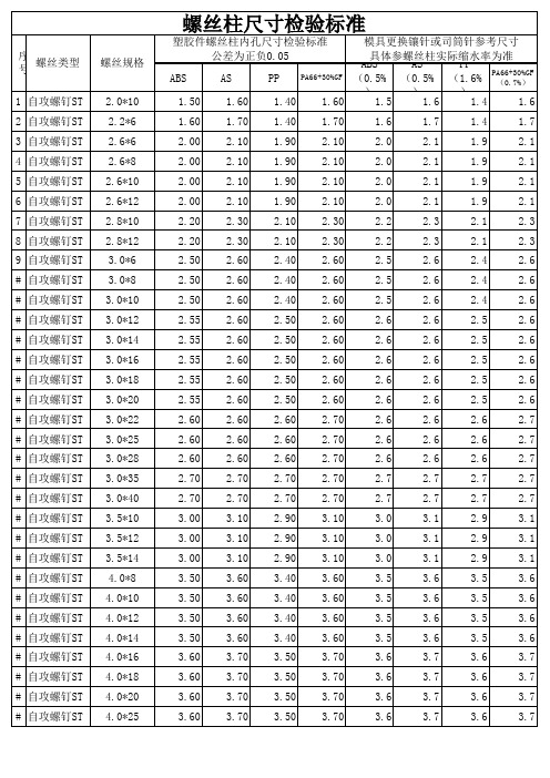
螺丝柱尺寸验收标准
中医穴位字典

足太阳膀胱经穴 足太阳膀胱经穴 足太阳膀胱经穴 足太阳膀胱经穴 足太阳膀胱经穴 足太阳膀胱经穴 足太阳膀胱经穴 足太阳膀胱经穴 足太阳膀胱经穴 足太阳膀胱经穴 足太阳膀胱经穴 足太阳膀胱经穴 足太阳膀胱经穴 足太阳膀胱经穴 足太阳膀胱经穴 足太阳膀胱经穴 足太阳膀胱经穴 足太阳膀胱经穴 足太阳膀胱经穴 足太阳膀胱经穴 足太阳膀胱经穴 足少阴肾经穴 足少阴肾经穴 足少阴肾经穴 足少阴肾经穴 足少阴肾经穴 足少阴肾经穴 足少阴肾经穴 足少阴肾经穴 足少阴肾经穴 足少阴肾经穴 足少阴肾经穴 足少阴肾经穴 足少阴肾经穴 足少阴肾经穴 足少阴肾经穴 足少阴肾经穴 足少阴肾经穴 足少阴肾经穴 足少阴肾经穴 足少阴肾经穴 足少阴肾经穴 足少阴肾经穴
神封 灵墟 神藏 或中 俞府 天池 天泉 曲泽 郄门 间使 内关 大陵 劳宫 中冲 关冲 液门 中诸 阳池 外关 支沟 会宗 三阳络 四渎 天井 清冷渊 消泺 臑会 肩髎 天髎 上关 颔厌 悬颅 悬厘
SF LX SC YZ SF TC TQ QZ XM JS NG DL LG ZC GC YM ZZ YC WG ZG HZ SYL SD TJ QLY XL NH JL TL TY YF CM LX JS EM EHL SZK TZL TH SG HY XL XL
魂门 阳纲 意舍 胃仓 盲门 志室 胞盲 秩边 合阳 承筋 承山 飞扬 附阳 昆仑 仆参 申脉 金门 京骨 束骨 足通谷 至阴 涌泉 然谷 太溪 大钟 水泉 照海 复溜 交信 筑宾 阴谷 横骨 大赫 气穴 四满 中注 盲俞 商曲 石关 阴都 腹通谷 幽门 步廊
HM YG YS WC HM ZS BH ZB HY CJ CS FY FY KL PC SM JM JG SG ZTG ZY YQ RG TX DZ SQ ZH FL JX ZB YG HG DH QX SM ZZ HS SQ SG YD FTG YM BL
STM8S系列单片机原理与应用(潘永雄)第1-5章章 (4)
第4章 STM8指令系统
4.1 ST汇编语言格式及其伪指令 4.2 STM8S寻址方式 4.3 STM8S指令系统
第4章 STM8指令系统
4.1 ST汇编语言格式及其伪指令
4.1.1 ST汇编常数表示法
在缺省情况下,ST汇编语言数制表示方式与Motorola 汇编语言格式相同,与Intel汇编语言表示方式不同。其中, 二进制、十六进制、十进制数表示方式如下:
第4章 STM8指令系统
伪指令不是CPU指令,汇编时不产生机器码。显然, 伪指令与CPU类型无关,而与汇编程序(也称为汇编器或编 译器)的版本有关。在汇编语言源程序中引用某一条伪指令 时,只需考虑用于将“汇编语言源程序”转化为对应CPU 机器语言指令的“汇编程序”是否支持所用的伪指令。
第4章 STM8指令系统
a*b(a MULT b) a ×b①
算术运算
a/b(或 a DIV b) a ÷b②
a-b
a-b
a+b
a+b
第4章 STM8指令系统
在表4-1中:
(1) a、b均为非负整数。
(2) 当指令中的常数为关系运算式的结果时,必须用
“{}”(花括号)将关系运算符括起来。例如:
LD A, #{HIGH 1234H}
第4章 STM8指令系统
在ST汇编中,位于00段内的地址标号后可带“ : ”(冒号), 也可以不带冒号,且标号一律顶格书写。
标号分为三大类:公共标号(Public),由本模块定义, 在整个项目内有效,项目内另一个模块引用时须用Extern伪 指令申明;局部标号,仅在本模块内有效;外部标号 (Extern),由另一个模块定义且声明为公共标号。此外,标 号还具有长度属性—字节,00页内的标号,带后缀 .B;字 标号,00段内的标号,带后缀 .W;长标号,存放位置没有 限制,带后缀.L。不带后缀长度属性说明符的标号默认为字 标号,即 .W类型。
南京聚诚电子 TX-ST8 12 16Pro 使用说明书

TX-ST8/12/16Pro使用说明书目录一、概述 (3)二、外观说明 (4)前面板 (4)后面板 (5)三、信号连接 (7)四、软件安装 (8)五、软件操作 (9)5.1设备连接 (9)5.1.1网络模式: (9)5.1.2串口模式: (10)5.1.3主界面: (10)5.2接收卡参数设置 (11)5.3显示屏设置 (11)5.3.1显示器阵列设置 (11)5.3.2插入显示单元 (12)5.3.3显示单元位置编辑 (12)5.3.4显示屏对应关系设置,如图22 (13)5.4多窗口设置 (14)5.4.1开设多个窗口 (15)5.4.2窗口剪切 (16)5.4.3字幕功能 (16)5.4.4热备份功能 (17)5.5保存 (18)5.6场景 (18)5.6.1场景调用 (18)5.6.2任务定时器 (19)5.6.3任务轮播 (19)添加多个场景设定有效时间轮回播放。
如图31 (19)5.7设备 (20)六、授权 (21)一、概述TX-ST8/12/16Pro多画面视频拼接发送处理一体机是专业级LED显示屏控制设备;具备强大的视频信号接收、拼接和处理能力,最大可驱动1千万点像素的LED大屏,支持HDMI2.0和DP1.2的4k@60hz高清数字信号同时还支持3路HDMI和1路DVI数字信号,多路信号间无缝切换;任意拼接、广播级缩放,最大支持8画面同时显示,可多台级联带载更大的LED显示屏。
TX-ST8/12/16Pro具备8/12/16个千兆网口输出,单机可支持最宽或最高15360x8192像素的LED显示屏。
同时,TX-ST8/12/16Pro具备一系列丰富实用的功能,提供灵活的屏幕控制和高品质的图像显示,可完美应用于各种规格LED显示屏。
产品特色:•最大带载1000万像素,输出单网口宽可达3840像素,最高可达3840像素.•最大输入分辨率4096×2160@60Hz,支持EDID管理.•全高清的数字信号接口,包括1路HDMI2.0、1路DVI、3路HDMI、1路DP1.2.•支持视频源任意切换,可根据显示屏分辨率对输入图像进行拼接、缩放.•软硬件可同时制作操作.•支持8画面同时开窗显示,位置、大小可任意调节.•支持亮度和色温调节,支持低亮高灰.•支持TX全系列接收卡、多功能卡.二、外观说明前面板序号名称功能1 3.2寸全彩液晶屏显示操作菜单及系统信息2按钮旋转进行选择或调节3功能键MENU,菜单ESC,退出BLACK,显示关闭打开LOCK,锁键4数字按键调取场景模式后面板输入接口1HDMI2.01路HDMI 2.0输入符合HDMI2.0标准,支持4096×2160@60Hz2DP1.21路DP1.2S输入符合DP1.2保准,支持4096×2160@60Hz3HDMI1.33路HDMI1.3输入支持1920×1200@60Hz4DVI 1路DVI输入VESA标准(支持1920×1200@60Hz),支持HDCP控制口1RJ45千兆网口,通过网络控制设备2RS232串口,通过串口控制设备33D-SYNC3D同步器接入接口,实现3D显示输出接口1OUT8/16路千兆网口,通过网络控制设备PUT电源交流电源接口1AC100-240V三、信号连接外观尺寸四、软件安装请从官网下载spliter软件安装包,也可在随机附带的U盘中找到安装软件,根据图例提示操作,完成软件安装。
- 1、下载文档前请自行甄别文档内容的完整性,平台不提供额外的编辑、内容补充、找答案等附加服务。
- 2、"仅部分预览"的文档,不可在线预览部分如存在完整性等问题,可反馈申请退款(可完整预览的文档不适用该条件!)。
- 3、如文档侵犯您的权益,请联系客服反馈,我们会尽快为您处理(人工客服工作时间:9:00-18:30)。
模拟习题 八
1. 计算机软件系统包括( )。
A. 系统软件和应用软件
B. 编辑软件和应用软件
C. 数据库软件和工具软件
D. 程序和数据
2. 已知X =-1010101,则X 的补码为( )。
A. 11010101
B. 11101011
C. 10101010
D. 10101011
3. 在8086CPU 的下列4种中断中,需要由硬件提供中断类型码(向量号)的是( )。
A. INTR
B. INTO
C. INT n
D. NMI
4. 下列8086CPU 标志寄存器的标志位中,不属于状态标志位的是( )。
A. OF
B. IF
C. AF
D. PF
5. 动态RAM 的特点是 ( )。
A. 速度高于静态RAM
B. 需刷新电路
C. 集成度低于静态RAM
D. 一般用于高速缓存
6. 下面指令正确的是( )。
A. SAR DX , 5
B. ADD AX , DL
C. MOV AX , [BP+20H]
D. MOV 80H , AL
7. 以下指令序列执行后,在屏幕上显示的是( )。
MOV AH, 02H MOV DL, 41H INT 21H A. 41H
B. A
C. a
D. 不确定
8. 当8086采样到Ready=0时,则CPU 将( )。
A. 执行停机指令
B. 插入等待周期
C. 执行空操作
D. 重新发送地址
9. 在DMA 方式下,数据从内存传送到外设的路径是( )。
A. 内存
CPU 总线 外设
B. 内存 DMA 控制器 外设
C. 内存 数据总线 外设接口 外设
D. 内存 外设 10. 只读存储器能够存储( )。
A. 程序代码和固定数据
B. 程序运行过程中需要保存的临时数据
C. 程序代码和临时数据
D. 固定数据和临时数据
1. 设堆栈指针(SP )=1FEH ,执行段内返回指令RET 后,(SP )= H 。
2. 8259中断控制器中总共有7个可编程的寄存器,它们分别用于接受CPU 送来的 命令字和 命令字。
一、单项选择题(每题2分,共20分)
二、填空题(每空1分,共10分)
3. 乘法指令MUL 的指令格式只有一个源操作数,若源操作数的类型属性为字节,则目的操作数在 中,若源操
作数的类型属性为字,则目的操作数在 中。
4. 8086/8088在最小方式下有关总线请求和总线应答的信号引线是 和 。
5. 外设与CPU 交换数据的方式有:程序直接控制方式、 方式和 方式,
其中 方式速度最快。
( )1. 80x86系统中内部中断优先级高于NMI 中断。
( )2. 指令指针寄存器存放的是下一条指令的偏移地址。
( )3. 8086CPU 执行一个总线周期最多可传送2个字节的数据。
( )4. 执行一条指令的时间一定为四个时钟周期。
( )5. 由逻辑地址可以唯一确定物理地址,因此,映射到该物理地址的逻辑地址是唯一的。
( )6. 指令指针IP 是通用寄存器。
( )7. 对数值83A7H 作逻辑非运算后的结果是7C58H 。
( )8. 设SOURCE 在数据段,其内容为01H 02H 03 04H 05H ,为字节变量;DESTINATION 在扩展段,则
下面程序段执行结束,DESTINATION 内的内容为05H 04H 03H 02H 01H 。
MOV SI,OFFSET SOURCE MOV DI,OFFSET DESTINATION MOV CX,5 CLD REP MOVSB
( )9. 8254的计数器0产生方波信号。
设输入时钟频率CLK0=2.5KHz ,计数初值为5000,则输出方波的正脉冲
宽度为1s 。
( )10. 80x86系统中内部中断优先级高于NMI 中断。
1. 8086CPU 在执行存储器或I/O 读写操作时,若存储器和外设的工作速度较慢,如何解决CPU 与存储器或外设之间的时间配合?(8分)
三、判断题(每题1分,共10分。
在正确论断前面的括号中填入“√”,否则填入“×”。
)
四、简答题(每题8分,共24分)
2. 说明下列指令的功能,其中TABLE 是已定义的变量名。
(1)MOV AX, TABLE (2)LODSB (3)MOV BL, [BX+SI] (4)DIV BX
3. 假如某中断的中断类型号为24,其中断服务子程序的中断向量为(2100H :0F10H),请把中断向量填入中断向量表中,并在右侧括号中标出偏移地址。
( )( )( )( )
1. 下面程序段执行后,(AX )= ,(BX )= 。
MOV AX ,92H MOV BX ,10H ADD BX ,70H ADC
AX ,BX
PUSH AX MOV AX ,20H POP BX ADD
AX ,BX
2. 已知一个长度为10H 个字节的数据块存放在DATA1中,要求用字符串传送指令将该数据块移动到DATA2中,将程序
填写完整。
DATA SEGMENT
DATA1 10H DUP (?) DATA2 10H DUP (?)
DATA ENDS CODE SEGMENT
ASSUME CS :CODE ,DS :DATA ,ES :DATA
START :MOV AX ,DATA
MOV DS ,AX
五、程序填空题(每空2分,共14分)
MOV ES ,AX MOV CX ,
MOV ,OFFSET DATA1 MOV ,OFFSET DATA2 MOV AH, 4CH INT 21H
CODE ENDS
END START
1. 编写一个子程序CONV ,将寄存器DX 中的一个16位二进制数以4位16进制数形式显示在屏幕上。
2. 字节型数组DAT0中第1个元素是数组中数据的个数,数据从第2个元素开始存放,编程统计数组中正数和负数的个数,并分开存储。
要求:DAT1和DAT2的第1个元素分别存放正数和负数的个数,正数和负数分别从DAT1和DAT2的第2个元素开始存放。
数据段定义已给出,请写出代码段。
DATA SEGMENT
DAT0 DB 100 DUP (?) DAT1 DB 100 DUP (?) DAT2 DB 100 DUP (?) DATA ENDS
六、编程题(每题11分,共22分)。
