Carbon Nanotube based composites a review
混凝土氧化石墨烯增强原理解析
混凝土氧化石墨烯增强原理解析混凝土氧化石墨烯增强原理解析1. 引言混凝土是一种广泛应用于建筑、基础设施和工程领域的材料,但它在某些方面存在一些不足之处,如强度、耐久性和韧性等。
为了提高混凝土的性能,研究人员一直在寻找新的增强材料。
而氧化石墨烯作为一种新兴的纳米材料,已经显示出在混凝土增强方面的潜力。
本文将深入探讨混凝土氧化石墨烯增强的原理,并分享对这个主题的观点和理解。
2. 氧化石墨烯的特性及应用2.1 石墨烯的定义石墨烯是一种由碳原子单层构成的二维晶体结构,具有独特的力学、电学和热学性质。
它是迄今为止最薄的材料,并且具有出色的导电性和导热性,具有广泛的应用潜力。
2.2 氧化石墨烯的制备方法氧化石墨烯是一种在石墨烯层表面附加氧原子的材料。
常用的制备方法包括Hummers法和Graphene Oxide法等。
这些方法可以将石墨烯氧化,同时也使其具有更高的分散性和可操作性。
2.3 氧化石墨烯在其他领域的应用氧化石墨烯在许多领域中的应用已被广泛研究和探索,包括电子器件、能源存储、传感器和生物医学等。
这些研究为混凝土中的应用提供了宝贵的经验和技术基础。
3. 氧化石墨烯在混凝土中的增强原理3.1 氧化石墨烯的增强效果混凝土中加入适量的氧化石墨烯可以显著提高其力学性能,包括抗压强度、抗弯强度和抗冲击强度等。
氧化石墨烯还可以提高混凝土的耐久性,如抗裂性和抗渗透性等。
这些增强效果可以通过氧化石墨烯与混凝土的相互作用来解释。
3.2 氧化石墨烯与水泥基质的相互作用氧化石墨烯与水泥基质之间发生的相互作用对于混凝土增强至关重要。
氧化石墨烯的高比表面积和极好的分散性使其能够与水泥基质有效接触,并形成强大的力学连接。
氧化石墨烯也可以作为晶核,促进水泥水化反应,加速水泥凝固和混凝土强度的形成。
3.3 氧化石墨烯与混凝土中裂缝和微裂缝的控制混凝土中常常存在着微观裂缝和微裂缝,这些缺陷会降低混凝土的耐久性和承载能力。
氧化石墨烯的添加可以填补这些裂缝,形成连续的增强区域。
高分子材料的热学性能与传导机制研究

高分子材料的热学性能与传导机制研究【引言】高分子材料在日常生活和工业应用中广泛使用。
了解高分子材料的热学性能以及传导机制对于进一步优化材料设计和应用具有重要意义。
【热学性能】高分子材料的热学性能主要包括导热性能和热稳定性。
导热性能是指高分子材料传导热量的能力,通常用热导率来衡量。
高分子材料的热导率较低,这是由于其结构中存在大量非晶态和无序结构。
然而,通过合成控制和分子设计等方法,可以提高高分子材料的导热性能。
热稳定性是指高分子材料在高温下耐受热量的能力。
高分子材料通常具有较好的热稳定性,可以承受高温环境而不发生严重的降解。
【传导机制】高分子材料的热传导主要通过分子振动和自由度传导机制实现。
分子振动是指高分子材料中分子围绕平衡位置进行振动传导热量的机制。
分子振动在高分子材料中起到了重要的热传导作用。
自由度传导机制是指通过分子链、分子段以及分子间的空间传导热量的机制。
高分子链之间的键相互作用和分子间空间结构对热传导具有重要影响。
此外,高分子材料的热传导还会受到晶型结构、分子链排列等因素的影响。
【热学性能与传导机制的关系】高分子材料的导热性能和热稳定性与其传导机制密切相关。
通过改变高分子材料的分子结构和组分,可以改善其导热性能和热稳定性。
在导热性能方面,通过增加高分子材料中的分子间空间或引入导热填料等方法,可以提高其导热性能。
在热稳定性方面,通过改善高分子链的稳定性和增加分子间键的强度,可增强高分子材料的耐高温性能。
【应用前景】高分子材料的热学性能和传导机制研究在许多领域具有重要应用前景。
例如,高分子材料在电子器件中的散热问题是一个关键挑战,通过优化材料的导热性能和传导机制可以提高电子器件的性能和可靠性。
此外,高分子材料在光伏、储能等领域的应用也需要考虑热学性能和传导机制的影响。
【结论】高分子材料的热学性能和传导机制研究对于优化材料性能和应用具有重要意义。
通过改变分子结构、组分和分子间空间等方法,可以改善高分子材料的导热性能和热稳定性。
碳纳米管聚合物基复合材料力学性能研究及应用前景
碳纳米管/聚合物基复合材料力学性能研究及应用前景摘要:碳纳米管以其独特的化学性能和物理性能成为复合材料的增强体,目前在许多科学研究领域中得到应用。
本文介绍了碳纳米管修饰的高分子复合材料在国内外的研究现状,进一步对几种碳纳米管/聚合物基复合材料的结构和力学性能进行综述。
在此基础上,分析并展望了今后碳纳米管/聚合物复合材料的发展趋势。
关键词:碳纳米管高分子复合材料力学性能Abstract:Carbon Nanotubes(CNT) become reinforced composite materials due to their unique chemical and physical properties , it applied in many scientific research currently. This paper introduces the current situation of CNT modified polymer composites in domestic and abroad, the structural and mechanical properties of several CNT / polymer composites were further reviewed . On this basis, we analyzes and prospects the future development trend of carbon CNT / polymer composites.Key words:carbon nanotubes,polymer,composites, the properties of mechanical碳纳米管(CNT)又名巴基管,是一种由管状的同轴纳米管组成的碳分子。
它由Lijima[1]在1991年发现,作为石墨、金刚石等碳晶体家族的新成员,由于其独特结构因而具有许多特异的物理性能,所以受到了各个领域科学家的高度重视,并且成为近年来材料领域的研究热点。
纳米材料在高分子纳米复合材料中的应用指南
纳米材料在高分子纳米复合材料中的应用指南引言:随着科学技术的发展,纳米材料在各个领域中都发挥着重要的作用。
高分子纳米复合材料是一种将纳米材料与高分子材料相结合的新型材料,具有优异的机械性能、导电性能、热稳定性以及其他特殊特性。
本文将详细探讨纳米材料在高分子纳米复合材料中的应用及其指南。
一、纳米材料的选择在高分子纳米复合材料中选择合适的纳米材料至关重要。
常见的纳米材料包括纳米粒子、纳米管、纳米片、纳米纤维等。
根据高分子材料的性质和复合材料的需求,选择合适的纳米材料种类。
例如,如果需要提高高分子材料的机械性能,可选择纳米粒子或纳米管填充剂。
如果需要增强其导电性能,可选择导电性能优异的纳米材料如石墨烯或金属纳米粒子。
二、纳米材料的表面改性很多纳米材料的表面存在一定的亲水性或疏水性,然而高分子材料常常对一方性表面较为敏感。
因此,在将纳米材料应用于高分子纳米复合材料中时,表面的改性是必要的。
改性的方法有:表面修饰、涂覆或包覆表面、引入功能基团等。
表面改性可以改善纳米材料与高分子材料之间的相容性,提高复合材料的力学性能。
三、纳米材料的分散性纳米材料具有极高的表面能,容易产生团簇现象,从而降低复合材料的力学性能。
因此,在高分子纳米复合材料的制备过程中,保持纳米材料的良好分散是至关重要的。
一种有效的方法是将纳米材料预先分散于适当的溶剂或表面活性剂中,以获得均匀的纳米分散液。
此外,超声波处理和机械研磨等方法也可以帮助提高纳米材料的分散性。
四、纳米材料的负载量和尺寸控制纳米材料的负载量和尺寸控制直接影响到高分子纳米复合材料的性能。
负载量的选择应综合考虑其对复合材料性能的影响和成本因素。
一般来说,适量的纳米材料负载可以有效提高材料的性能,但过高的负载量可能会导致复合材料的脆性增加。
此外,通过控制纳米材料的尺寸,可以进一步调控复合材料的性能。
例如,纳米粒子的尺寸越小,复合材料的强度和刚度越高。
五、纳米材料与高分子材料的相容性纳米材料与高分子材料的相容性对于高分子纳米复合材料的性能至关重要。
国外碳纳米管复合材料研究现状
国外碳纳米管复合材料研究现状Carbon nanotubes (CNTs) have been widely studied as promising reinforcing materials in composite materials due to their unique mechanical, electrical, and thermal properties. In recent years, research on carbon nanotube composites has been focused on enhancing the mechanical properties, electrical conductivity, and thermal stability of the materials. This review provides an overview of the current state of research on foreign carbon nanotube composites, focusing on the different types of carbon nanotubes, their incorporation into various matrices, and their applications in different fields.There are two main types of carbon nanotubes: single-walled carbon nanotubes (SWCNTs) and multi-walled carbon nanotubes (MWCNTs). SWCNTs are composed of a single layer of carbon atoms arranged in a cylindrical structure, while MWCNTs are composed of multiple layers of carbon atoms arranged in concentric cylinders. SWCNTs are known for their higher mechanical strength and electrical conductivity compared to MWCNTs, but MWCNTs are easier to produce in larger quantities.Carbon nanotubes can be incorporated into a wide range of polymeric, ceramic, and metal matrices to form composite materials with enhanced properties. The most common methods for incorporating carbon nanotubes into matrices include solution mixing, melt mixing, and chemical vapordeposition. The choice of matrix material and processing method can greatly affect the properties of the resulting composite material.One of the key advantages of carbon nanotube composites is their exceptional mechanical properties. The high aspect ratio and strong covalent bonds of carbon nanotubes make them ideal reinforcing materials for improving the strength and stiffness of composite materials. Studies have shown that the addition of carbon nanotubes can significantly increase the tensile strength, flexural strength, and impact resistance of composite materials. Additionally, carbon nanotubes can also improve the toughness and fatigue resistance of composite materials, making them suitable for a wide range of structural applications.In addition to their mechanical properties, carbon nanotube composites are also known for their excellent electrical conductivity. Carbon nanotubes have a high electrical conducti vity due to their delocalized π-electron system, making them ideal materials for applications in electronics, sensors, and energy storage devices. Studies have shown that the addition of carbon nanotubes can significantly increase the electrical conductivity of composite materials, making them suitable for use in conductive coatings, electromagnetic shielding, and antistatic materials.Furthermore, carbon nanotube composites also exhibit enhanced thermal stability due to the excellent thermal conductivity of carbon nanotubes. Thehigh thermal conductivity of carbon nanotubes allows for efficient heat transfer within the composite material, leading to improved thermal management and heat dissipation properties. Studies have shown that the addition of carbon nanotubes can significantly increase the thermal conductivity and heat resistance of composite materials, making them suitable for applications in aerospace, automotive, and electronic devices.Overall, research on foreign carbon nanotube composites has shown promising results in enhancing the mechanical, electrical, and thermal properties of composite materials. The unique properties of carbon nanotubes make them ideal reinforcing materials for improving the performance of composite materials in various applications. Further research is needed to optimize the processing methods and matrix materials to fully exploit the potential of carbon nanotube composites in different fields.。
材料科学与工程专业英语第二版 翻译
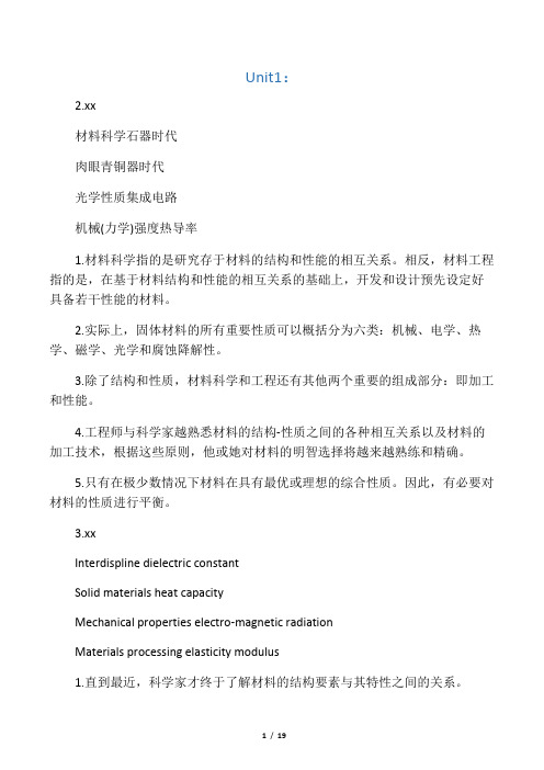
Unit1:2.xx材料科学石器时代肉眼青铜器时代光学性质集成电路机械(力学)强度热导率1.材料科学指的是研究存于材料的结构和性能的相互关系。
相反,材料工程指的是,在基于材料结构和性能的相互关系的基础上,开发和设计预先设定好具备若干性能的材料。
2.实际上,固体材料的所有重要性质可以概括分为六类:机械、电学、热学、磁学、光学和腐蚀降解性。
3.除了结构和性质,材料科学和工程还有其他两个重要的组成部分:即加工和性能。
4.工程师与科学家越熟悉材料的结构-性质之间的各种相互关系以及材料的加工技术,根据这些原则,他或她对材料的明智选择将越来越熟练和精确。
5.只有在极少数情况下材料在具有最优或理想的综合性质。
因此,有必要对材料的性质进行平衡。
3.xxInterdispline dielectric constantSolid materials heat capacityMechanical properties electro-magnetic radiationMaterials processing elasticity modulus1.直到最近,科学家才终于了解材料的结构要素与其特性之间的关系。
It was not until relatively recent times that scientists came to understand the relationship between the structural elements of materials and their properties .2.材料工程学主要解决材料的制造问题和材料的应用问题。
Material engineering mainly solve the problems of materials processing and materials application.3.材料的加工过程不但决定了材料的结构,同时决定了材料的特征和性能。
化学实验报告 聚苯胺的合成与表征 7138

聚苯胺的合成与表征摘要:聚苯胺在不同的酸的环境中合成,优化聚苯胺的合成条件。
用过硫酸铵作氧化剂,改变不同的投料比.酸类.温度等,合成聚苯胺产品。
计算聚苯胺的合成产率。
用合成的聚苯胺做红外光谱检测结构,并比对氧化态与本征态的聚苯胺的谱图。
关键词:聚苯胺投料比酸度红外光谱1.绪论:聚苯胺(PANI)是一种得到广泛应用的导电聚合物,例如用作太阳能电池材料[1,2]超级电容器电极材料[3]催化剂载体[4]电化学传感器[5]防腐蚀材料[6]等.聚苯胺的制备方法有很多种,不同的合成条件下可以得到不同微观形貌的聚苯胺,例如万梅香等人[7]研究了聚苯胺纤维的合成,通过改变氧化剂可以很好地控制聚苯胺纤维的径;AYADMohamadM等人[8]研究了软模板法制备聚苯胺纳米管; 王学智等人[9]采用界面聚合方法制备了聚苯胺纳米棒.2.实验部分2.1仪器与试剂:苯胺(AR 天津博迪化工股份有限公司),使用之前用蒸馏出来再用;过硫酸铵(AR 天津市科密欧化学试剂有限公司);盐酸(AR 北京化工);硫酸(AR 北京化工);高氯酸(AR 北京化工);磷酸(AR 天津市富宇精细化工有限公司);乙腈(AR 天津市科密欧化学试剂有限公司);二甲基亚砜(AR 广东光华科技股份有限公司);乙醇.乙酸.甲苯.四氢呋喃等溶剂均是分析纯。
85-Z恒温磁力搅拌器(重庆银河实验仪器有限公司);HC21006恒温槽(重庆银河实验仪器有限公司);磁力加热搅拌器(郑州长城科工);蒸馏装置;使用水均是一次蒸馏水。
2.2聚苯胺的合成:)n原理——------→(将苯胺蒸馏出来备用;配制不同1mol/l的无机酸150ml, 加入0.05mol蒸馏的苯胺,在不同浓度的氧化剂硫酸铵,在恒温水不同的温度下。
搅拌24小时,过滤时用100ml 乙酸先冲洗,再用蒸馏水冲洗至PH=6,干燥,称量。
氧化合成参杂态的聚苯胺,计算产率。
取2克的参杂态聚苯胺加入稀氨水100ml搅拌1小时脱氢离子制得本征态的聚苯胺。
从衣食住行四个方面举例介绍纳米作文

从衣食住行四个方面举例介绍纳米作文Nanotechnology has revolutionized various aspects of our lives, from the way we dress to the way we eat, live, and travel. Nanotechnology has been incorporated into the textile industry, allowing for the production of stain-resistant, wrinkle-free, and even self-cleaning clothing. For example, nanoscale particles are often added to fabrics to create a barrier that prevents water, dirt, and other substances from penetrating the material. This means that people can spend less time and money on dry cleaning and stain removal, thus reducing the environmental impact of clothing production and maintenance.纳米技术已经彻底改变了我们生活的各个方面,从我们穿衣服的方式到我们吃饭、居住和旅行的方式。
纳米技术已经被应用到纺织业,使得可以生产抗污、防皱甚至自清洁的服装。
例如,纳米尺度的颗粒经常被添加到织物中,以创建一个屏障,防止水、污垢和其他物质渗透到材料中。
这意味着人们可以花更少的时间和金钱在干洗和去污上,从而减少服装生产和维护对环境的影响。
In terms of food, nanotechnology has revolutionized packaging and preservation techniques, allowing for longer shelf lives and reducedfood waste. Nanoscale materials can be used to create packaging that protects against oxygen, moisture, and bacteria, preserving the quality and safety of food products. Additionally, nanotechnology has been utilized to improve the efficiency of food production, such as enhancing the nutrient content of food through nanoencapsulation and improving the delivery of nutrients in functional foods.在食品方面,纳米技术已经彻底改变了包装和保鲜技术,使得食物可以更长时间地保存,减少食品浪费。
石墨烯增强铜基复合材料的性能研究

Value Engineering0引言随着科学技术不断发展,对铜的性能需求也不断提高。
例如:对铜的导电导热性能、机械性能、耐磨性能以及耐腐蚀等。
目前,第二相掺杂是提高铜基体材料性能最有效的方法之一,通常可分为金属类掺杂和碳类掺杂。
金属元素掺杂虽然能提高铜基体的机械性能和耐磨性能,但导电和导热性能会大幅度降低[1];碳纤维(CNFs )作为增强相制备的复合材料虽然在导电、导热和耐磨性方面表现优异,但由于铜基体和CNFs 界面润湿性差使机械性能显著下降;掺入碳纳米管(CNTs )使铜基体各方面性能都优于CNFs ,但CNTs 制备困难、价格昂贵而且不易在铜基体中均匀并有序的分散[2]。
相比之下,石墨烯由于特殊的二维结构,在导电、导热以及力学性能方面表现非常优异,并且制备难度相对CNTs 较低,因此将石墨烯作为铜基体材料的增强相十分合适[3]。
本实验通过掺杂不同含量的石墨烯,研究了不同石墨烯含量对铜基体的机械性能、导热性能和导电性能的影响。
1实验部分1.1实验原材料聚酰亚胺(PI )膜;无水乙醇(EtOH );5~10μm 铜粉。
1.2实验制备与表征仪器激光雕刻机(SK-F30)、磁力搅拌台(RCT );水浴超声机(KH -3200DE );离心机(AVANTIJ -15);真空干燥箱(DZF-6020);等离子放电烧结炉(FCT )。
扫描电子显微镜(JSM-6610);多功能力学性能实验机(Instron 9657);激光热导仪(LFA457);多功能数字式四探针测试仪(ST-2258C )。
1.3实验流程实验流程主要是[4,5]:①石墨烯的制备。
激光以6W 的功率刻蚀PI 膜制备石墨烯,随后将PI 膜上表面的石墨烯剥落并研磨。
②湿法粉末混合阶段。
在装有50ml 无水乙醇、10g 铜粉末的烧杯里分别加入0g 、0.05g 、0.1g 、0.15g 和0.2g 的石墨烯粉末并且搅拌均匀。
为了使粉末状的铜和石墨烯更加充分的分散于乙醇溶液中,将铜和石墨烯的粉末混合悬浊液持续超声1小时改善分散性。
Carbon Nanotubes碳纳米管精彩介绍

Connect two graphite rods to a power supply, place them millimeters apart, and throw switch. At 100 amps, carbon vaporizes in a hot plasma.
Can produce SWNT and MWNTs with few structural defects
Carbon Nanotubes
By Bryan Sequeira Bertug Kaleli Murshed Alam Farooq Akbar Zac Lochner
What are Carbon Nanotubes ?
Carbon nanotubes are fullerene-related structures which consist of graphene cylinders closed at either end with caps containing pentagonal rings
Arc discharge method
Chemical vapor deposition
Place substrate in oven, heat to 600 C, and slowly add a carbon-bearing gas such as methane. As gas decomposes it frees up carbon atoms, which recombine in the form of NTs
Tubes tend to be short with random sizes and directions
NTs are usually MWNTs and often riddled with defects
聚氨酯弹性体_碳纳米管复合材料的制备与性能

第25卷第1期高分子材料科学与工程Vol.25,No.1 2009年1月POLYMER MATERIALS SCIENCE AND ENGINEERINGJan.2009聚氨酯弹性体/碳纳米管复合材料的制备与性能伍金奎,王 峰,夏和生(高分子材料工程国家重点实验室,四川大学高分子研究所,四川成都610065)摘要:通过三种方法制备了碳纳米管(CN T s)改性的热塑性聚氨酯弹性体(T P U ),研究了碳纳米管对热塑性聚氨酯弹性体的增强、增韧效果。
考察了T P U/CNT s 复合材料的力学性能、热性能及流变性能。
结果表明,碳纳米管能有效地实现对T PU 的增强和增韧,在CNT 含量为1%时,拉伸强度从5416M Pa 提高到6610M Pa,断裂伸长率从684%提高到801%。
SEM 表明CN T 在T P U 中分散性良好。
通过XRD 、DSC 和T GA 表征了复合材料的微观结构和热性能。
关键词:碳纳米管;聚氨酯弹性体;固相力化学中图分类号:T B383 文献标识码:A 文章编号:1000-7555(2009)01-0111-04收稿日期:2008-01-28基金项目:国家自然科学基金面上项目(50673060),973国家重点基础研究发展计划资助(2007CB714701)和四川省杰出青年学科带头人培养计划(06ZQ026-032)通讯联系人:夏和生,主要从事聚合物纳米复合材料、力化学研究, E -mail:xi ahs@碳纳米管(CNTs)具有长径比大、力学强度高、良好的电导率和热导率等优点,成为聚合物理想的增强纤维[1]。
碳纳米管/聚合物复合材料[2]既能保持聚合物基体的弹性、强度和模量等性能,又能使电导率和热导率得到提高。
制备碳纳米管/聚合物复合材料的方法有原位聚合法[3]和机械共混法(包括溶液共混、熔融共混和固相共混[4~6])。
但这两种方法面临的问题是:(1)实现CNTs 在基体中的均匀分散而不出现团聚和缠结;(2)需改善CNTs 与聚合物基体间的相互作用力。
多壁碳纳米管对聚苯硫醚力学性能的增强效应_蒋震宇

dEc ) 在 2.4~64 GPa 范围内变 dV f
化
[4, 28]
dEc 。本研究中, 在碳纳米管含量较低时 (0.37 dV f
vol%) 达到了相当高的水平 (~60.5 GPa) , 然而当碳纳米 管含量超过 0.73 vol% 后, 逐渐降低至中等水平 (~15.8 GPa) 。在提高聚苯硫醚纳米复合材料模量和强度的同 时, 碳纳米管的引入降低了聚苯硫醚的延展性。纳米复 合材料的断裂应变随着碳纳米管的含量单调下降, 当碳 纳米管含量为 5.97 vol% 时, 纳米复合材料的断裂应变 仅为未填充聚苯硫醚的 54%。该结果反映了碳纳米管 对聚合物高分子链运动的约束作用。
第17届全国复合材料学术会议论文
多壁碳纳米管对聚苯硫醚力学性能的增强效应
Reinforcing Effect of Multi-Walled Carbon Nanotubes on the Mechanical Properties of Polyphenylene Sulfide
华南理工大学土木与交通学院 [ 摘要 ] 聚苯硫醚是现今主要的高性能热塑性材 料之一, 基于聚苯硫醚的高性能复合材料, 已逐渐用于 航空制造。通过双螺杆挤出技术将多壁碳纳米管分散 至聚苯硫醚基体, 并对形成的纳米复合材料的力学性 能进行了研究。实验表明, 多壁碳纳米管能够明显增 强聚苯硫醚的模量和强度。基于上述结果, 分析了影 响多壁碳纳米管对聚苯硫醚增强效应的主要因素, 对 Halpin–Tsai 模型进行了修正。修正后的模型经验证可 适用于预测基于其它高性能热塑性基体的碳纳米管增 强复合材料的力学性能。 关键字:碳纳米管 聚苯硫醚 纳米复合材料 力学性能 弹性模量 [Abstract] Polyphenylene sulfide (PPS)/multi-walled carbon nanotube (MWCNT) composites were prepared using a melt-blending procedure combining twin-screw extrusion with centrifugal pre-mixing. The mechanical properties of PPS were markedly enhanced by the incorporation of MWCNTs. Halpin-Tsai equations, modified with an efficiency factor, were used to model the elastic properties of the nanocomposites. The theoretically predicted modulus showed good agreement with the experimental results for both PPS and polyetheretherketone (PEEK). Keywords: Carbon nanotubes Polyphenylene sulfide Nanocomposites Mechanical properties Elastic modulus 蒋震宇 黄健彰
材料科学与工程专业英语1-18单元课后翻译答案
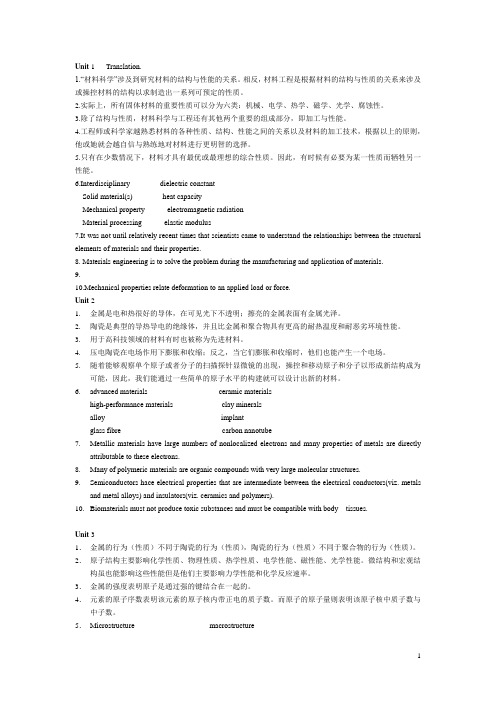
Unit 1 Translation.1.“材料科学”涉及到研究材料的结构与性能的关系。
相反,材料工程是根据材料的结构与性质的关系来涉及或操控材料的结构以求制造出一系列可预定的性质。
2.实际上,所有固体材料的重要性质可以分为六类:机械、电学、热学、磁学、光学、腐蚀性。
3.除了结构与性质,材料科学与工程还有其他两个重要的组成部分,即加工与性能。
4.工程师或科学家越熟悉材料的各种性质、结构、性能之间的关系以及材料的加工技术,根据以上的原则,他或她就会越自信与熟练地对材料进行更明智的选择。
5.只有在少数情况下,材料才具有最优或最理想的综合性质。
因此,有时候有必要为某一性质而牺牲另一性能。
6.Interdisciplinary dielectric constantSolid material(s) heat capacityMechanical property electromagnetic radiationMaterial processing elastic modulus7.It was not until relatively recent times that scientists came to understand the relationships between the structural elements of materials and their properties.8. Materials engineering is to solve the problem during the manufacturing and application of materials.9.10.Mechanical properties relate deformation to an applied load or force.Unit 21.金属是电和热很好的导体,在可见光下不透明;擦亮的金属表面有金属光泽。
国外碳纳米管复合材料研究现状
国外碳纳米管复合材料研究现状Carbon nanotubes (CNTs) have attracted great attention in the field of composite materials due to their excellent mechanical, electrical, and thermal properties. When combined with other materials, such as polymers or ceramics, CNTs can enhance the overall performance of the composite. Researchers around the world are working on various methods to improve the dispersion and bonding between CNTs and the matrix material to achieve the desired properties in the final composite.碳纳米管(CNTs)由于其优异的机械、电学和热学性能,在复合材料领域受到了广泛关注。
当与其他材料结合时,如聚合物或陶瓷,CNTs可以提高复合材料的整体性能。
全球各地的研究人员正在努力寻找不同的方法改善CNTs与基体材料之间的分散性和结合力,以实现最终复合材料中所期望的性能。
One of the challenges in the research of carbon nanotube composites is achieving a uniform dispersion of CNTs in the matrix. Due to their high aspect ratio and tendency to agglomerate, CNTs are often difficult to disperse evenly in the composite material.Improper dispersion can lead to weak interfacial bonding, which limits the enhancement of mechanical properties. Various techniques, such as functionalization of CNTs or the use of surfactants, have been explored to improve dispersion and enhance the overall performance of the composite.碳纳米管复合材料研究中的一个挑战是实现CNTs在基体中的均匀分散。
CARBON NANOTUBE COMPOSITE
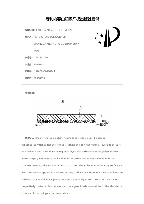
专利名称:CARBON NANOTUBE COMPOSITE发明人:PENG-CHENG SONG,QIU-CENZHANG,CHANG-HONG LIU,SHOU-SHANFAN申请号:US11831904申请日:20070731公开号:US20080063860A1公开日:20080313专利内容由知识产权出版社提供专利附图:摘要:A carbon nanotube/polymer composite is described. The carbonnanotube/polymer composite includes at least one polymer material layer and at least one carbon nanotube/polymer composite layer. The carbon nanotube/polymer layer includes a polymer material and a plurality of carbon nanotubes embedded in thepolymer material, wherein the carbon nanotube/polymer layer includes a top surface and a bottom surface opposite to the top surface, at least one of the top surface and bottom surface contacts with the adjacent polymer material layer, and the carbon nanotubes respectively contact at least one respective adjacent carbon nanotube to thereby yield a network of contacting carbon nanotubes.申请人:PENG-CHENG SONG,QIU-CEN ZHANG,CHANG-HONG LIU,SHOU-SHAN FAN 地址:Beijing CN,Beijing CN,Beijing CN,Beijing CN国籍:CN,CN,CN,CN更多信息请下载全文后查看。
单壁碳纳米管聚氨酯复合物的反射和吸收对电磁干扰屏蔽的贡献

Reflection and absorption contributions to the electromagneticinterference shielding of single-walled carbonnanotube/polyurethane compositesZunfeng Liu,Gang Bai,Yi Huang,Yanfeng Ma,Feng Du,Feifei Li,Tianying Guo,Yongsheng Chen *Key Laboratory for Functional Polymer Materials &Center for Nanoscale Science and Technology,Institute of Polymer Chemistry,Nankai University,Tianjin 300071,ChinaReceived 1August 2006;accepted 17November 2006Available online 19January 2007AbstractThe electromagnetic interference (EMI)shielding of well dispersed single-walled carbon nanotube (SWCNT)/polyurethane compos-ites was studied and the results show that they can be used as effective and lightweight shielding materials.The EMI shielding of the composite shows a reflection-dominant mechanism,while a shift from reflection to absorption was observed with increased SWCNT loading and frequency.This is explained using EMI shielding theory and the intrinsic properties of the components.Ó2006Elsevier Ltd.All rights reserved.1.IntroductionAs commercial,military,and scientific electronic devices and communication instruments are used more and more widely,electromagnetic interference (EMI)shielding of radio frequency radiation continues to be a more serious concern in this modern society.Light weight EMI shielding is needed to protect the workspace and environment from radiation coming from computers and telecommunication equipment as well as for protection for sensitive circuits [1].Compared to conventional metal-based EMI shielding materials,electrically conducting polymer composites have gained popularity recently because of their light weight,resistance to corrosion,flexibility and processing advanta-ges [2–9].The EMI shielding efficiency (SE)of a composite material depends on many factors,including the filler’s intrinsic conductivity,dielectric constant,and aspect ratio [7,9].The high conductivity,small diameter,high aspect ratio,and super mechanical strength and so on of carbon nanotubes (CNTs)make them an excellent option to createconductive composites for high-performance EMI shield-ing materials at low filling concentration.Recently,multi-walled carbon nanotubes (MWCNTs)have been studied with various polymer matrix,including polystyrene (PS)[1],epoxy [10],poly(methyl methacrylate)(PMMA)[11],polyaniline (PANI)[1],polypyrrole (PPY)[1],PU [10,12,13],etc.,for the possible applications as effective and light weight EMI shielding materials and the EMI shielding has been attributed mainly due to the reflection contribution [10,14,15].When Fe is hybridized with CNT/polymer composites,it is observed that the main con-tribution to total EMI SE is absorption rather than reflec-tion [16,17].Also the influences of wall defects [10],aspect ratio [10],and alignment [18]of CNTs on the EMI shield-ing have been investigated.But the composite materials with single-walled carbon nanotubes (SWCNTs)have been largely unexplored for this area so far [10,12].Very recently we reported the first EMI shielding study of the composite materials of SWCNTs with epoxy as matrix in the fre-quency range of 10MHz–1.5GHz [10].But owing to many different,and in many cases superior,properties compared with MWCNTs,SWCNTs warrant more studies for light and effective EMI shielding materials.0008-6223/$-see front matter Ó2006Elsevier Ltd.All rights reserved.doi:10.1016/j.carbon.2006.11.020*Corresponding author.Tel.:+862223500693;fax:+862223499992.E-mail address:yschen99@ (Y.Chen)./locate/carbonCarbon 45(2007)821–827Polyurethane(PU)elastomers are widely used high-per-formance materials with many unique properties,including good elasticity,high impact strength and elongation,resis-tance to low temperature,and excellent bio-compatibility [19,20].And these properties have made them widely used in many civil and military industries[21].In this paper we prepared well dispersed PU/SWCNT composites using a simple physical blending method.An EMI SE up to17dB at the band range of8.2–12.4GHz(so called X band)was obtained for PU/SWCNT composites with20wt%SWCNT loading.The composites show a percolation threshold as low as$0.2wt%.The investigation in the shielding mecha-nism shows a reflecting-dominant mechanism,whereas a contribution shift behavior toward to absorption was observed with increased SWCNT loading and frequency. Using EMI shielding theory,this trend is explained with the intrinsic properties of the components.At high SWCNT loadings and we found the intrinsic properties favored the absorbing ability rather than the reflecting one.2.Experimental2.1.Materials and measurementsSWCNTs were prepared in our laboratory using a mod-ified arcing method[22].Using AFM[23],we found the bundles for the raw SWCNTs(AP SWCNTs)had an aver-age diameter=5.95nm,average length=1430nm.The AP SWCNTs have specific surface area of1500m2/g and contain about50wt%SWCNTs.N,N-dimethyl formamide (DMF,AR)was used as purchased.Polyurethanes were supplied by Tianjin Polyurethane Co.(Mn=20,000,hard-ness=85,density=1.34,synthesized from Diphenyl methane4,4-diisocyanate(MDI),1,4-butadiol,and poly-ethylene glycol adipate(Mn=1000)).The dc electrical conductivity of the SWCNT-epoxy composites was determined using the standard four-point contact method on rectangular sample slabs in order to eliminate contact-resistance effects at room temperature. Data were collected with a Keithley SCS4200.The EMI shielding effectiveness and complex(relative)permittivity data of SWCNT/PU composites were measured with the slabs of dimension of22.86mm·10.16mm·2mm tofit waveguide sample holder using a HP vector network ana-lyzer(HP E8363B)in8.2-12.4GHz(X band).And total 201data points were taken within this frequency range for each sample.The PU/SWCNT samples were freeze-frac-tured in liquid nitrogen and gold coated for imaging on a Hitachi S-3500N scanning electron microscope(SEM). 2.2.Preparation of the PU/SWCNT composites and their filmsWe used the conventional solution process to prepare the composites and theirfilms.As an example,the follow-ing describes the process to prepare the composite with 5wt%SWCNT loading.SWCNTs(2.15g)were added into DMF(1500mL),stirred for2h,and then the mixture was sonicated for2h using a high power sonic bath(300W, modeled KQ-300DB)to disperse SWCNTs in DMF.Then PU(43g)dissolved in300mL of DMF was added to above SWCNT suspension and the formed mixture was then stir-red mechanically for2h.The mixture was further soni-cated for2h using the above sonic bath.Note that more DMF(to keep SWCNT concentration to be$1.5mg/ mL)was used for higher SWCNT loading composites. After the mixture was again stirred mechanically for2h, it was then cast in a large mold to let solvent to evaporate at$140°C.Then the PU/SWCNTfilms were pealed offfrom the mold and vacuum dried at80°C for48h.After a hot pressure process at150°C and15MPa,aflatfilm of PU/SWCNT composite with5wt%SWCNT loading was obtained.The sample was then cut to slabs with desired sizes and then the surfaces of the slabs were pol-ished if necessary.Other composites with different loadings were prepared similarly.As a control,pure PUfilms and slabs were prepared using the same process.3.Results and discussion3.1.Theoretical backgroundFor a transverse electromagnetic wave propagating into a sample with negligible magnetic interaction,the total shielding efficiency(SE T)of the sample is expressed as Eq.(1)[7,24,25]:SE T¼10logðP in=P outÞ¼SE AþSE RþSE Ið1Þwhere P in and P out are the power incident on and transmit-ted through a shielding material.The SE T is expressed in decibels(dB).The SE A and SE R are the absorption and reflection shielding efficiencies,respectively.The third term (SE I)is a positive or negative correction term induced by the reflecting waves inside the shielding barrier(multi-reflections),which is negligible when SE A P15dB [24,25].The terms in Eq.(1)can be described asSE A¼8:68a lð2ÞSE R¼20logj1þn j24j n jð3ÞSE I¼20log1À1Àn21þn2expðÀ2c lÞð4Þwhere the parameters a,n,and c are defined as following equations,l is the thickness of the shielding barrier.a¼ð2p=k0Þffiffiffiffiffiffiffiffiffiffiffiffiffiffiffiffiffiffiffiffiffiffiffiffiffiffiffiffiffiffiffiffiffiffiffiffiffiffie rðffiffiffiffiffiffiffiffiffiffiffiffiffiffiffiffiffiffiffi1þtan2dpÇ1Þ2sð5Þn¼ffiffiffiffiffiffiffiffiffiffiffiffiffiffiffiffiffiffiffiffiffiffiffiffiffiffiffiffiffiffiffiffiffiffiffiffiffiffie rðffiffiffiffiffiffiffiffiffiffiffiffiffiffiffiffiffiffiffi1þtan2dpÆ1Þsþiffiffiffiffiffiffiffiffiffiffiffiffiffiffiffiffiffiffiffiffiffiffiffiffiffiffiffiffiffiffiffiffiffiffiffiffiffiffie rðffiffiffiffiffiffiffiffiffiffiffiffiffiffiffiffiffiffiffi1þtan2dpÇ1Þsð6Þc¼ð2p=k0Þffiffiffiffiffiffiffiffiffiffiffiffiffiffiffiffiffiffiffiffiffiffiffiffiffiffiffiffiffiffiffiffiffiffiffiffiffiffie rðffiffiffiffiffiffiffiffiffiffiffiffiffiffiffiffiffiffiffi1þtan2dpÇ1Þ2sþið2p=k0Þffiffiffiffiffiffiffiffiffiffiffiffiffiffiffiffiffiffiffiffiffiffiffiffiffiffiffiffiffiffiffiffiffiffiffiffiffiffie rðffiffiffiffiffiffiffiffiffiffiffiffiffiffiffiffiffiffiffi1þtan2dpÆ1Þ2sð7Þ822Z.Liu et al./Carbon45(2007)821–827where k0is the wave length,e r the real part of complex rel-ative permittivity,the±andÇsigns are applied for posi-tive and negative e r,respectively.[25]The loss tangent tan d=e i/e r=re0e r,where e i is the imaginary part of the rela-tive permittivity;x=2p F,where F is the frequency;e0is the dielectric constant in free space and r the conductivity. Here we use the alternative conductivity(r ac)to express the conducting ability of the alternative electromagnetic wave in the composites:r ac=xe0e r.The estimation of the SE in this study is in the far-field limit[25],which assumes that the distance from the source to the shielding barrier is long enough and not to apply near-shielding effects.From Eqs.(1)–(7),SE T is tuned by a,n,and l.The intrinsic parameters for the SE T are a and n,which are determined by e r and r ac. From these equations,one can expect high shielding effi-ciency for materials with higher e r and r ac.The thickness of the material l is an extrinsic parameter which can be used to control SE A and SE I.The imaginary part of the complex permittivity e i,also called loss factor,indicates the ability of the materials to absorb radio wave.The term tan d,also called loss tangent,indicates the ability of a material toconvert stored energy to heat.Thus,large values of loss factor and loss tangent would indicate a better radio absorbing material[26].The material with tan d)1exhibits as a good conduc-tor and the material with tan d(1exhibits as a weak con-ductor[27].In case of tan d)1,a can be approximated as a%(xlr/2)1/2and n%(1+i)(r/2xe)1/2,where l is the per-meability.This indicates that for the highly conducting materials,the EMI shielding(including absorption and reflection)shall be decided mainly by r,not e r.In the case of tan d(1,a%(r/2)(l/e0e r)1/2,indicating that the elec-tromagnetic energy dissipation can also occurred in the weak conductors where permeability plays a more impor-tant role.In the present study however,tan d%1(see below),so the above approximated formulas can not be used,and both r ac and e r must be considered when estimat-ing the EMI shielding efficiency.3.2.DC conductivity of the PU/SWCNT compositesAs seen from the EMI theory above,the EMI perfor-mance of composites is highly coupled with thefiller’s intrinsic conductivity,dielectric constant,and aspect ratio[7,9].Fig.1shows the dc conductivity(r DC)of PU/ SWCNT composites as a function of SWCNT mass fraction (p).As can be seen,the conductivity of the PU/SWCNT composites exhibits a dramatic increase at low loadings, indicating the formation of percolating network.For exam-ple,below0.25wt%,the conductivity of SWCNT compos-ites displays a dramatic increase of6orders of magnitude and the conductivity reaches2.2·10À4S/cm at20wt% SWCNT loading.This value is10orders of magnitude higher than that of the pure PU matrix(i.e.,1.2·10À14 S/cm).Thus far,studies on the conductivity of SWCNT–poly-mer composites have been reported low thresholds at various volume fractions with different fabrication methods and different SWCNT aspect ratio[8,28].For real applica-tions,it is critical to have lowfilling threshold,since lower filling fractions imply smaller perturbations of bulk physi-cal properties as well as lower cost.It is well known that the conductivity of a conductor–insulator composite follows the critical phenomena around the percolation threshold (Eq.(8))[29]:r DC/ðmÀm cÞbð8Þwhere r DC is the composite conductivity,m is the SWCNT volume fraction,m c is the percolation threshold and b is the critical exponent.Because the densities of the polymer and SWCNTs are similar,we assume that the mass fraction,p, and the volume faction,m,of the SWCNTs in the polymer are almost the same.As shown in the inset to Fig.1for the log(r DC)vs log(pÀp c)plot,a least-squares analysis of the fits using Eq.(1),shows that the threshold volume p c for the composites was strongly bounded by the regions be-tween the highest insulating and lowest conducting points and the PU/SWCNT composite conductivity agrees very well with the percolation behavior predicted by Eq.(8).The bestfit of the conductivity data to the log-log plot of the power laws gave p c%0.2%,and b=3.74,according to Eq.(8),as shown in the inset in Fig.1.While computer models of conductivity percolation give a critical exponent value of2for a3-d rigid rod network,various values from 1.3to5.3have been reported for different CNT-polymer composites.These included SWCNT composites with crit-ical exponent values of1.5for polyimide[30],1.3and2.68 for epoxy[10,28],and2–3for different SWCNT materials with epoxy[8].Similarly,various values from2.15to5.31 for MWCNT composites have been reported[17].A perco-lation threshold of$16%has been predicted in two-phase random composites when the conducting micro scaledfill-ers with sphere shape are used.However,the percolation threshold p c %0.2wt%in this work is $2orders smaller than the theoretical result and also comparable to other SWCNT composite materials [8,28,31].This low threshold value can be attributed to the large one dimensional aspect ratio and well dispersion of SWCNTs in the composites.The well dispersion was also confirmed with the SEM image in Fig.2for the 20wt%loading of SWCNTs.The SEM image clearly shows that the SWCNTs were distrib-uted rather homogeneously.Note electrostatic dissipation applications typically require a conductivity of 10À5S/cm and thus with only addition of 5wt%SWCNTs,these PU/SWCNT composites should be able to be used for many electrostatic dissipation applications too.plex relative permittivity vs SWCNT loadings and frequenciesRecent studies have shown that SWCNT/polymer com-posites posses high real permittivity (polarization,e r )as well as imaginary permittivity (adsorption or electric loss factor,e i )in the 0.5–2GHz [10]and 500MHz–5.5GHz ranges [32],indicating that SWCNT/polymer composites could be used as light weight and effective electromagnetic shielding mate-rials.We thus measured the complex permittivity of SWCNT/PU composites in the frequency range of 8.2–12.4GHz (X band).Fig.3shows the complex relative per-mittivity spectra of the composites containing 0%–20wt%SWCNTs.As can be seen,the real (e r )and imaginary (e i )permittivity increase dramatically as the concentration of SWCNTs increases from 5to 20wt%.The highest values of the real and imaginary permittivity parts for the compos-ite with 20wt%SWCNT loading reach 38and 26,respec-tively.Overall the real and imaginary parts of permittivity for this PU/SWCNT composites with 20wt%SWCNTs range from 32to 38and 24to 26in the frequency of 8.2–12.4GHz.Furthermore,at low loadings,both the real and imaginary parts of permittivity are almost independent to the frequencies in the range we measured with the same loading.But at higher (e.g.20wt%)loading,the values of the real part of the permittivity intend to decrease with increasing of frequency,while the imaginary values still keep little change.The absolute values of the measured per-mittivity are of the same order of magnitude as those reported by Grimes et al.for SWCNT/polymer composites in the 0.5–5.5GHz range [32].These trends are important to understand the EMI mechanism discussed below.A peak between 8.5and 9.5GHz was found for the composites (10,15,and 20wt%)and it becomes stronger with higher SWCNT loadings.This result implies the existence of a res-onance behavior,which is expected when the composite is highly conductive and skin effect becomes significant [16].Che et al.[16]reported that the frequency at which the peak occurs is determined by the aspect ratio of thenano-scaledFig. 2.A typical SEM image of PU/SWCNT composite containing 20wt%SWCNTs after freeze-fractured in liquid nitrogen and goldcoated.Fig.3.Real (e r )and imaginary (e i )parts of the relative permittivity in the frequency range of 8.2–12.4GHz.824Z.Liu et al./Carbon 45(2007)821–827fillers and they found that the Fe-encapsulated carbon nano-cages have a peak at about 5GHz and the Fe-encap-sulated MWCNTs have a peak at about 7GHz.In this paper,the composites have a resonance peak at about 9GHz.This is probably because a high aspect ratio of SWCNTs compared to that of MWCNTs.3.4.EMI shielding effectiveness of the PU/SWCNT compositesFig.4shows the EMI shielding effectiveness over the fre-quency range of 8.2–12.4GHz for PU/SWCNT composites with various SWCNT loadings.As expected from the above data about conductivity and permittivity,the EMI shielding effectiveness increases with increasing content of SWCNTs in the composite and the contribution to the EMI shielding should come from the addition of SWCNTs.It is also observed that the shielding effectiveness of the composites almost keeps unchanged except for a slight decrease with increasing the frequency for the same load-ing.The shielding effectiveness of the composites contain-ing 20wt%SWCNTs is measured to be 16–17dB over the frequency range of 8.2–12.4GHz.Fig.5shows the tan d values of the composites,from which it can be seen that the tan d values of the composites are in the range of 0.25–0.8,very close to 1,indicating that the composites in this work do not act as good nor weak conductors [27].Therefore the intrinsic parameters e r and r ac must be considered to evaluate the EMI SE.The EMI SE was thus plotted versus e r and r ac ,respectively at 8.2GHz as an example in Fig.6.The data in Fig.6fall on smooth curves,and similar dependence of EMI SE on r ac and e r was obtained.From the fitted curve in Fig.6a,we can see a dramatic increase in shielding effectiveness with the initial variation of r ac ,and then EMI SE increases slowly with the continuous increase in r ac .A similar trendwas observed for the plotting of EMI versus e r .Recall that both r ac and e r increase with SWCNT loadings in Figs.1and 3.The above results indicate that EMI shielding effec-tiveness increases much faster at low SWCNT loadings,which becomes slower with higher SWCNT loadings.3.5.Contribution shift from reflection to absorption at higher SWCNT loading and frequencyAs discussed in Section 3.1,the EMI SE has three con-tributions:reflectivity (R ),Absorptivity (A )and the multi-reflecting correction of waves inside the shielding barrier.For a very approximate analysis,the multi-reflecting part could be neglected,particularly for the cases when total SE A >15dB.Thus we could use the equation of 100%=A +T +R to get all the values of A from the experimental results of T and R to evaluate each contribution for the total shielding.The results are summarized in Fig.7.From Fig.7,it can be seen that the major contribution for EMI SE still comes from the reflection;which is consis-tent with the literatures [14,15]for CNT composites.At low loadings,both A and R increases with increasing load-ing.More interestingly,we can see a general trend at high loadings (e.g.>10wt%loadings)that the absorption con-tribution for EMI shielding increases while the reflection contribution decreases with the increase in the SWCNT loading at the same frequency.For example,in the case of the results at 12.4GHz,the reflectivity of the composite with a p =5wt%is as high as 46.4%,and the absorptivity 18.3%.As the p increases to 10wt%,the reflectivity increases to 69.8%and the absorptivity increases slightly to 21.7%.As the p continues to increase to 15wt%,a con-tribution shift behavior is observed:the reflectivity decreases from 69.8%to 52.8%and the absorptivity increases to 42.7%,almost doubles the one at 10wt%SWCNTs’loading (21.7%).As the p continues toincreasesFig.4.EMI shielding effectiveness for PU/SWCNT composites in the frequency range of 8.2–12.4GHz.Fig.5.The tan d values of PU/SWCNT composites in the frequency range from 8.2to 12.4GHz.Z.Liu et al./Carbon 45(2007)821–827825to 20wt%,the reflectivity continues to decreases to 51.4%and the absorptivity increases to 45.9%.Furthermore,the higher the frequency,the more evident the trend is.Such a contribution shift behavior relates closely to the inner properties of the composite.As we know that the loss tangent tan d indicates the ability of a material to convert stored energy into heat,i.e.,tan d provides an indication for how well the material can be penetrated by an electrical field and how well it dissipates electromagnetic energy as heat.It can be seen from Fig.5that tan d increases with the increase in SWCNT loadings.Tan d is almost zero for the sample without SWCNTs,indicating pure PU can hardly attenuate/absorb the radio wave.As SWCNT load-ing increases to 5wt%and 10wt%,tan d increases to $0.25and 0.55,respectively.Thus A values increase as observed in Fig.7.This is also evident from Eqs.(2)–(6).From Eqs.(2)–(6),we can see at higher frequency,with increasing tan d ,SE A shall increase faster than SE T .A similar trend was found as the increase of frequency with the same SWCNT loading from Fig.7,i.e.,the reflec-tivity decreases and absorptivity increases for the same loading of SWCNTs .For example,for the case of p =20wt%,the reflectivity decreases from 76.0%to 61.5%and then to 51.4%as the frequency increases from 8.2to 10.3and then to 12.4GHz.Such a contribution shift behavior is more evident for the samples with a higher loading.Again this trend could be understood from Figs.3and 5and Eq.(2)–(6).At the same loading,we can see the values of tan d increases as frequency increases but the e r keeps almost unchanged at lower loading and slightly decreases with higher loadings (see Fig.3).Recall the tan d indicates the material capability to absorb radio wave energy;the above trend thus would become expected.This can also be evident from Eq.(2)–(6),as SE A would increase rela-tively faster than SE R when e r keeps almost unchanged with increasing tan d for the same loading of SWCNTs.From Fig.6it can be seen that at the initial stage,EMI SE increases much faster with increase of r ac and e r and from Fig.7we can see a greater increase in R and a smaller increase in A at the same stage.This indicates that at low SWCNT loadings,r ac and e r affect more R than A with the increasing SWCNT loading.Also from Fig.6in the region with high values of r ac and e r ,EMI SE increases slower and from Fig.7we can see a decrease in R and an increase in A .These results thus indicates that at high SWCNT loading,r ac and e r contributes more to A than to R with increasing SWCNT loading.4.ConclusionIn this paper,PU/SWCNT composites with well-dis-persed SWCNTs were prepared using a simple physical mixing method and an EMI shielding effectiveness of $17dB was achieved at the SWCNT loading of 20wt%.Together with PU excellent properties and wide applica-tions,the EMI shielding properties endowed bySWCNTFig.7.Reflectivity (R )and absorptivity (A )vs SWCNT loadings at different frequencies.826Z.Liu et al./Carbon 45(2007)821–827as afiller shall make these composites one of the ideal can-didates for EMI application.The EMI shielding of the composites show a reflecting-dominated mechanism, whereas with the increase in SWCNT loading and the fre-quency,a contribution shift from reflection to absorption was observed at higher loadings.By analyzing the trans-mission behavior of the electromagnetic wave and the intrinsic properties of the composites,we attribute this phe-nomenon to the increase of the tan d due to the increase of the imaginary part of the dielectric constant of the compos-ite materials.Our observations call for a better understand-ing for the EMI shielding mechanism to optimize the design of EMI shielding materials using SWCNTs.Future work will concentrate on studies for this energy transition behavior and the application of this property in electro-magnetic wave absorption.AcknowledgementsWe gratefully acknowledge thefinancial support from MOST(#2003AA302640and2006CB0N0700),MOE (#20040055020)and the NSF Tianjin(#043803711)of China.References[1]Wang Y,Jing X.Intrinsically conducting polymers for electromag-netic interference sheilding.Polym.Adv.Technol.2005;16(4):344–51.[2]Yang YL,Gupta MC,Dudley KL,Lawrence RW.Conductivecarbon nanofiber-polymer foam structures.Adv.Mater.2005;17(16): 1999–2003.[3]Xiang CS,Pan YB,Liu XJ,Sun XW,Shi XM,Guo JK.Microwaveattenuation of multiwalled carbon nanotube-fused silica composites.Appl.Phys.Lett.2005;87(12):1231031–3.[4]Joo J,Epstein AJ.Electromagnetic-radiation shielding by intrinsicallyconducting polymers.Appl.Phys.Lett.1994;65(18):2278–80.[5]Luo X,Chung DDL.Electromagnetic interference shielding reaching130dB usingflexible graphite.Carbon1996;34(10):1293–4.[6]Luo XC,Chung DDL.Electromagnetic interference shielding usingcontinuous carbon-fiber carbon-matrix and polymer-matrix posites Part B1999;30(3):227–31.[7]Joo J,Lee CY.High frequency electromagnetic interference shieldingresponse of mixtures and multilayerfilms based on conducting polymers.J.Appl.Phys.2000;88(1):513–8.[8]Bryning MB,Islam MF,Kikkawa JM,Yodh AG.Very lowconductivity threshold in bulk isotropic single-walled carbon nano-tube-epoxy composites.Adv.Mater.2005;17(9):1186–91.[9]Chung DDL.Electromagnetic interference shielding effectiveness ofcarbon materials.Carbon2001;39(2):279–85.[10]Li N,Huang Y,Du F,He X,Lin X,Gao H,et al.Electromagneticinterference(EMI)shielding of single-walled carbon nanotube epoxy composites.Nano Lett.2006;6(6):1141–5.[11]Kim HM,Kim K,Lee SJ,Joo J,Yoon HS,Cho SJ,et al.Chargetransport properties of composites of multiwalled carbon nanotube with metal catalyst and polymer:application to electromagnetic interference shielding.Curr.Appl.Phys.2004;4(6):577–80.[12]Ma CCM,Huang YL,Kuan HC,Chiu YS.Preparation andelectromagnetic interference shielding characteristics of novel car-bon-nanotube/siloxane/poly-(urea urethane)nanocomposites.J.Polym.Sci.,Part B:Polym.Phys.2005;43(4):345–58.[13]Wu HL,Ma CCM,Yang YT,Kuan HC,Yang CC,Chiang CL.Morphology,electrical resistance,electromagnetic interference shield-ing and mechanical properties of functionalized MWNT and poly(urea urethane)nanocomposites.J.Polym.Sci.,Part B:Polym.Phys.2006;44(7):1096–105.[14]Yang YL,Gupta MC.Novel carbon nanotube-polystyrene foamcomposites for electromagnetic interference shielding.Nano Lett.2005;5(11):2131–4.[15]Yang YL,Gupta MC,Dudley KL,Lawrence RW.A comparativestudy of EMI shielding properties of carbon nanofiber and multi-walled carbon nanotubefilled polymer composites.J.Nanosci.Nanotechnol.2005;5(6):927–31.[16]Che RC,Peng LM,Duan XF,Chen Q,Liang XL.MicrowaveAbsorption Enhancement and Complex Permittivity and Permeabil-ity of Fe Encapsulated within Carbon Nanotubes.Adv.Mater.2004;15(5):401–5.[17]Kim HM,Kim K,Lee CY,Joo J,Cho SJ,Yoon HS,et al.Electricalconductivity and electromagnetic interference shielding of multi-walled carbon nanotube composites containing Fe catalyst.Appl.Phys.Lett.2004;84(4):589–91.[18]Cheng HZ,Jou WS,Lin PT,Huang CC,Chen EC.A novel CNTS/polymer/PE composite with high electromagnetic shielding.Annu.Tech.Conf.Antec.Conf.Proc.2004;2:1662–7.[19]Li YJ,Hanada T,Nakaya T.Surface modification of segmentedpolyurethanes by grafting methacrylates and phosphatidylcholine polar headgroups to improve hemocompatibility.Chem.Mater.2006;11(3):763–70.[20]Shirasaka H,Inoue S,Asai K,Okamoto H.Polyurethane ureaelastomer having monodisperse poly(oxytetramethylene)as a soft segment with a uniform hard segment.Macromolecules2000;33(7):2776–8.[21]Randall D,Lee S.The Polyurethanes Book.New York:John Wiley&Sons;2002.5-30.[22]Lv X,Du F,Ma Y,Wu Q,Chen Y.Synthesis of high quality single-walled carbon nanotubes at large scale by electric arc using metal compounds.Carbon2005;43(9):2020–2.[23]Du F,Ma Y,Lv X,Huang Y,Li F,Chen Y.The synthesis of single-walled carbon nanotubes with controlled length and bundle size using the electric arc method.Carbon2006;44(7):1327–30.[24]Schulz RB,Plantz VC,Brush DR.Shielding theory and practice.Electromagnetic Compatibility,IEEE Trans.1988;30(3):187–201. [25]Joo J,Epstein AJ.Electromagnetic radiation shielding by intrinsicallyconducting polymers.Appl.Phys.Lett.1994;65(18):2278–80. [26]Yussuf AA,Sbarski I,Hayes JP,Solomon M,Tran N.Microwavewelding of polymeric-microfluidic devices.J.Micromech.Microeng.2005;15(9):1692–9.[27]Holzheimer T.A broadband materials measurements technique usingthe full frequency extent of the network analyzer.2002Anten.appl.symp.2002.[28]Kim B,Lee J,Yu I.Electrical properties of single-wall carbonnanotube and epoxy composites.J.Appl.Phys.2003;94(10): 6724–8.[29]Stauffer D,Aharony A.Introduction to Percolation Theory.Seconded.London:Taylor&Francis;1992.17-30.[30]Park C,Ounaies Z,Watson KA,Crooks RE,Smith Jr J,et al.Dispersion of single wall carbon nanotubes by in situ polymerization under sonication.Chem.Phys.Lett.2002;364(3):303–8.[31]Grunlan JC,Mehrabi AR,Bannon MV,Bahr JL.Water-BasedSingle-Walled-Nanotube-Filled Polymer Composite with an Exceptionally Low Percolation Threshold.Adv.Mater.2006;16(2): 150–153.[32]Grimes CA,Mungle C,Kouzoudis D,Fang S,Eklund PC.The500MHz to5.50GHz complex permittivity spectra of single-wall carbon nanotube-loaded polymer composites.Chem.Phys.Lett.2000;319(5-6):460–4.Z.Liu et al./Carbon45(2007)821–827827。
碳纳米管二氧化钛复合材料作为可见光活性光催化剂对DBT的光氧化
碳纳米管二氧化钛复合材料作为可见光活性光催化剂对DBT的光氧化BARMALA Molood;BEHNOOD Mohammad;OMIDKHAH Mohammad Reza【期刊名称】《中南大学学报(英文版)》【年(卷),期】2018(025)007【摘要】近年来液体燃料中硫的脱除越来越重要.加氢脱硫是脱除硫的常用方法,但用这种方法消除噻吩类化合物比较困难.光催化法是目前正在开发的一种环境条件下脱除噻吩的替代方法.在半导体中,二氧化钛作为光催化剂显示出了良好的潜力;然而,电子空穴的快速复合阻碍了它的工业应用.降低复合率的一种方法是将碳纳米管与半导体结合起来.本文以正丁酸四乙酯(TEOT)和四异丙醇钛(TTIP)为前驱体,制备了不同质量比的纳米碳管(MWCNT)/二氧化钛复合材料.研究了在有氧和无氧条件下,二苯并噻吩(DBT)对正己烷的光催化去除作用.结果表明,当氧化钛与氧化钛之比为1时,去除效果最好.当比值超过此数时,由于光散射而使DBT去除率降低.TEOT 制备的复合材料在DBT去除率方面表现出较好的效果.结果表明该复合材料是一种可见光活性光催化剂,在含氧条件下表现出较好的性能.光催化去除DBT的动力学为一级反应,在最佳条件下得到的去除速率常数为0.7 h-1.%Sulfur removal from liquid fuels has increased in importance in recent years. Although hydrodesulfurization is the usual method for removing sulfur, the elimination of thiophene compounds using this process is difficult. Photocatalysis is an alternative method being developed for thiophene removal at ambient conditions. Among semiconductors, titania has shown good potential as a photo-catalyst; however, quick recombination ofelectron holes hinders its commercial use. One way to decrease the recombination rate is to combine carbon nanotubes with a semiconductor. In this work, multiwall carbon nanotube (MWCNT) / titania composites were prepared with different mass ratios of MWCNT to titania using tetraethyl orthotitanate (TEOT) and titanium tetra isopropoxide (TTIP) as precursors of titania. Dibenzothiophene (DBT) photocatalytic removal from n-hexane was measured in both the presence and absence of oxygen. The results indicated that the best removal occurred when the MWCNT to titania ratio was 1. When the ratio exceeded this number, DBT removal efficiency decreased due to light scattering. Also, the composites prepared by TEOT exhibited better efficiency in DBT removal. The research findings suggested that the obtained composite was a visible light active photocatalyst and exhibited better performance in the presence of oxygen. Kinetics of photocatalytic DBT removal was a first-order reaction with removal rate constant 0.7 h-1 obtained at optimum conditions.【总页数】9页(P1642-1650)【作者】BARMALA Molood;BEHNOOD Mohammad;OMIDKHAH Mohammad Reza【作者单位】Chemical Engineering Department, Dezful Branch, Islamic Azad University, Azadegan Highway, P.O. Box: 313, Dezful, Iran;Department of Petroleum and Chemical Engineering, Science and Research Branch, Islamic Azad University, Tehran, Iran;Chemical Engineering Department,Tarbiat Modares University, Jalal Ale Ahmad Highway, P.O. Box: 14155-143, Tehran, Iran【正文语种】中文因版权原因,仅展示原文概要,查看原文内容请购买。
碳纳米管增强金属基复合材料的研究进展
碳纳米管增强金属基复合材料的研究进展何天兵;胡仁伟;何晓磊;李沛勇【摘要】Carbon nanotube reinforced metal matrix composites(CNT/MMCs)owing to high specific strength and specific elastic modulus as well as exceptional thermal and electrical properties,possess great potential in aerospace applications.Based on the analysis on the published literatures,the pro-cessing techniques and the CNT/metal interface research advances was evaluated,and some typical properties were summarized.It is pointed out that,the dispersion of carbon nanotubes,and interfacial characteristics between CNT and metal matrix would be mainly important research areas in future.%碳纳米管增强金属基复合材料由于高的比强度、比模量以及优异的热、电性能在航空航天领域具有很好的应用潜力,本文在分析大量文献的基础上,评述该类材料的制备技术和界面研究进展,对其典型性能进行归纳,指出碳纳米管的分散技术以及碳管、基体之间的界面特性应该是今后本领域的重点研究方向。
【期刊名称】《材料工程》【年(卷),期】2015(000)010【总页数】11页(P91-101)【关键词】碳纳米管;金属基复合材料;制备技术;分散性;界面【作者】何天兵;胡仁伟;何晓磊;李沛勇【作者单位】北京航空材料研究院,北京 100095;总参陆航部装备发展办公室,北京 100082;北京航空材料研究院,北京 100095;北京航空材料研究院,北京100095【正文语种】中文【中图分类】TB333航空航天技术的迅速发展对材料的性能提出了越来越高的要求,传统材料已经存在一定的局限性,如铝合金弹性模量低,热膨胀系数大;钛合金热导率低等。
磁性粘土矿物的制备及其吸附性能研究
磁性粘土矿物的制备及其吸附性能研究肖思佳;胡洋;林茵军;黎钰婵;丁春霞;刘德明【摘要】本研究以粘土矿物蒙脱石为主要原料,通过对其表面进行磁性Fe3 O4负载,制得磁性粘土矿物,并借助红外光谱仪(FT-IR)和X-射线衍射仪(XRD)对其结构进行了表征,同时探讨了磁性粘土矿物对甲基蓝的吸附性能,结果表明,在吸附剂投加量为2.5 g/L、pH为7、反应时间为8 h的条件下,磁性粘土矿物对初始浓度为200 mg/L的甲基蓝去除率高达98.24%,且吸附后的磁性粘土矿物重复使用4次后,其吸附率仍能保持在54.80%.【期刊名称】《广州化工》【年(卷),期】2018(046)021【总页数】4页(P31-33,45)【关键词】甲基蓝;蒙脱石;磁性;吸附;再生【作者】肖思佳;胡洋;林茵军;黎钰婵;丁春霞;刘德明【作者单位】湖南农业大学理学院, 湖南长沙 410128;湖南农业大学理学院, 湖南长沙 410128;湖南农业大学理学院, 湖南长沙 410128;湖南农业大学理学院, 湖南长沙 410128;湖南农业大学理学院, 湖南长沙 410128;湖南农业大学分析测试中心, 湖南长沙 410128【正文语种】中文【中图分类】X523印染废水排放量大、毒性大、水质复杂,已成为重点环境污染源之一[1]。
仅在中国,每年就有超过7.2亿吨的纺织印染废水未经任何处理直接排入水体,给整个生态系统带来了破坏性后果。
染料废水处理方法主要有生物法、化学降解法及吸附法,其中吸附法具有操作简易、成本低及效率高等特点[2-5]。
粘土矿物是自然界中广泛分布的一类非金属矿藏资源,具有资源丰富、价格低廉、比表面积大、孔隙多和极性强等优点,是一类用于吸附重金属和有机污染物的吸附剂,在污染土壤修复及水环境治理领域发挥独特的作用[6-8]。
但是粘土矿物大多为微孔结构,其吸附重金属或有机污染物后难以脱附,再次利用较困难;而且负载有重金属或有机污染物的吸附剂难以从水体中分离出来[9-10]。
载药(甲磺酸帕珠沙星)水凝胶的制备及其药物缓释性能
载药(甲磺酸帕珠沙星)水凝胶的制备及其药物缓释性能于金刚;黄可龙;唐金春【摘要】以甲磺酸帕珠沙星(1)为药物,以壳聚糖修饰的多壁碳纳米管(MWCNT-CS)/壳聚糖半互穿网络水凝胶(C)为载体,采用浸泡法合成了不同MWCNT-CS含量(0%,2.5%,10.0%)的三种载药水凝胶[C0(1),C2.5(1)和C1000(1)].研究了C(1)中MWCNT-CS含量以及pH对1释放性能的影响.结果表明,C10.0(1)具有较好的缓释性能.%Depending upon chitosan(CS) modified multiple-walled carbon nanotubes(MWCNT-CS)amount(0%, 2.5%, 10.0% ), three drug-loaded hydrogel[ C0 (1), C2.5 (1), C10.0 (1) ] were prepared by soaking method using Pazufloxacin mesilate(1) as the drug and MWCNT-CS/semi-IPN hydrogels as the drug carriers. Effect of content of CS-MWCNT in C (1) and pH on controlled release performance of 1 were investigated. The results showed that the C10.0(1) possess good controlled release performance.【期刊名称】《合成化学》【年(卷),期】2011(019)002【总页数】4页(P166-169)【关键词】甲磺酸帕珠沙星;多壁碳纳米管;半互穿网络水凝胶;制备;缓释性能【作者】于金刚;黄可龙;唐金春【作者单位】中南大学,化学化工学院,湖南,长沙,410083;中南大学,化学化工学院,湖南,长沙,410083;中南大学,化学化工学院,湖南,长沙,410083【正文语种】中文【中图分类】O636随着医学科学和纳米科学研究的不断发展,纳米粒子载药体系正凭借其独特的优点已成为药物控制释放和靶向释放研究的主要方向[1~3]。
- 1、下载文档前请自行甄别文档内容的完整性,平台不提供额外的编辑、内容补充、找答案等附加服务。
- 2、"仅部分预览"的文档,不可在线预览部分如存在完整性等问题,可反馈申请退款(可完整预览的文档不适用该条件!)。
- 3、如文档侵犯您的权益,请联系客服反馈,我们会尽快为您处理(人工客服工作时间:9:00-18:30)。
Journal of Minerals & Materials Characterization & Engineering, Vol. 4, No.1, pp 31-46, 2005 Printed in the USA. All rights reserved31Figure 1: Single wall carbon nanotubesCarbon Nanotube Based Composites- A ReviewRupesh Khare*, Suryasarathi BoseMumbai University Institute of Chemical Technology (UICT)*rupesh_uict@*author to whom all the correspondence should be addressedAbstract:Carbon nanofibers and nanotubes are promising to revolutionise several fields in material science and are a major component of nanotechnology. Further market development will depend on material availability at reasonable prices. Nanotubes have a wide range of unexplored potential applications in various technological areas such as aerospace, energy, automobile, medicine, or chemical industry, in which they can be used as gas adsorbents, templates, actuators, composite reinforcements, catalyst supports, probes, chemical sensors, nanopipes, nano-reactors etc. In this paper, recent research on carbon nanotube composites are reviewed. The interfacial bonding properties, mechanical performance, electrical percolation of nanotube/polymer and ceramic are also reviewed.INTRODUCTIONCarbon nanotubeElemental carbon in the sp2hybridization can form a variety1of amazing structures. Apart fromthe well-known graphite, carboncan build closed and open cageswith honeycomb atomicarrangement. The first suchstructure to be discovered was theC60 molecule by Kroto2 et al.Although various carbon cageswere studied, it was only in 1991,when Iijima3 observed for the firsttime tubular carbon structures. Thenanotubes consisted of up toseveral tens of graphitic shells (so-called multi-walled carbonnanotubes (MWNT)) withadjacent shell separation of ∼0.34nm, diameters of ∼1 nm and highlength/diameter ratio. Two years later, Iijima and Ichihashi4 and Bethune et al.5 synthesized single-walled carbon nanotubes (SWNT) (figure1).32Rupesh Khare, Suryasarathi BoseVol. 4, No. 1Figure 2: tip of multi wall carbon nanotubeFigure 3: Arc-discharge scheme. Two graphite electrodes are used to produce a dc electric arc-discharge in inert gas atmosphere.There are two main types ofcarbon nanotubes 6 that can havehigh structural perfection. Single-walled nanotubes (SWNT) consistof a single graphite sheet seamlesslywrapped into a cylindrical tube.Multiwalled nanotubes (MWNT)comprise an array of such nanotubesthat are concentrically nested likerings of a tree trunk (figure 2).Synthesis of CN The MWNT were first discovered 1 in the soot of the arc-discharge method by Iijima. This method had been used long before in the production of carbon fibers and fullerenes. It took two more years for Iijima and Ichihashi 4, and Bethune 5 et al. to synthesize SWNT by use of metal catalysts in the arc-discharge method in 1993.Significant progress was achieved by laser-ablation synthesis of bundles of aligned SWNT with small diameter distribution by Smalley and co-workers 7. Catalytic growth of nanotubes by the chemical vapor decomposition (CVD) method was first used by Yacaman 8 et al.Arc-dischargeIn 1991, Iijima reported thepreparation of a new type of finite 1 carbonstructures consisting of needle-like tubes 3.The tubes were produced using an arc-discharge evaporation method similar to thatused for the fullerene synthesis. The carbonneedles, ranging from 4 to 30 nm in diameterand up to 1 mm in length, were grown on thenegative end of the carbon electrode used forthe direct current (dc) arc-dischargeevaporation of carbon in an argon-filledvessel (100 Torr) (see figure 3). Ebbesen andAjayan 9 reported large-scale synthesis of MWNT by a variant of the standard arc-discharge technique. Iijima used an arc-discharge chamber filled with a gas mixture of 10 Torr methane and 40 Torr argon. Twovertical thin electrodes were installed in the center of the chamber. The lower electrode,the cathode, had a shallow dip to hold a small piece of iron during the evaporation. The arc-discharge was generated by running a dc current of 200 A at 20 V between theVo. 4, No 1. Carbon Nanotube Based Composites- A Review33Figure 4:Laser-ablation scheme: Laser beam vaporizes target of a mixture of graphite and metal catalyst (Co, Ni)in a horizontal tube in a flow of inert gas at controlledpressure and in a tube furnace at 1200 0C. The nanotubes are deposited on a water-cooled collector outside the furnace electrodes. The use of the three components—argon, iron and methane, was critical for the synthesis of SWNT. The nanotubes had diameters of 1 nm with a broad diameter distribution between 0.7 and 1.65 nm. In the arc-discharge synthesis of nanotubes,Bethune 5 et al. used as anodes thin electrodes with bored holes, which were filled with a mixture of pure powdered metals (Fe, Ni or Co) and graphite. The electrodes were vaporized with a current of 95–105 A in 100–500 Torr of He. Large quantities of SWNT were generated by the arc-technique by Journet 10 et al. The arc was generated between two graphite electrodes in a reactor under helium atmosphere (660 mbar).Laser-ablationIn 1996, Smalley and co-workers produced high yields(>70%) of SWNT by laser-ablation (vaporization) of graphiterods with small amounts 7 of Niand Co at 1200 0C (see figure 4).The tube grows until too manycatalyst atoms aggregate on theend of the nanotube. The largeparticles either detach or become over-coated with sufficient carbon to poison the catalysis. This allows the tube to terminate with a fullerene-like tip or with a catalyst particle. Both arc-discharge andlaser-ablation techniques have theadvantage of high (>70%) yields of SWNT and the drawback that (1) they rely on evaporation of carbon atoms from solid targets at temperatures >3000 0C, and (2) the nanotubes are tangled which makes difficult the purification and application of the samples.Chemical vapour deposition (CVD)Despite the described progress of synthetic techniques 12 for nanotubes, there still remained two major problems in their synthesis, i.e. large scale production and ordered synthesis. But, in 1996 a CVD method emerged as a new candidate for nanotube synthesis. This method is capable of controlling growth direction on a substrate and synthesising 13 a large quantity of nanotubes. In this process a mixture of hydrocarbon gas, acetylene, methane or ethylene and nitrogen was introduced into the reaction chamber. During the reaction, nanotubes were formed on the substrate by the decomposition of the hydrocarbon at temperatures 700–900o C and atmospheric 14 pressure The process has two main advantages: the nanotubes are obtained at much lower34Rupesh Khare, Suryasarathi BoseVol. 4, No. 1Figure 5: CVD reactor temperature, although this is at the cost of lower quality, and the catalyst can be deposited on a substrate, which allows for the formation of novel structures.The substrateThe preparation of the substrate and the use of the catalyst deserve special attention, because they determine the structure of the tubes. The substrate is usually silicon, but also, glass and alumina are used. The catalysts are metal nanoparticles, like Fe, Co and Ni, which can be deposited on silicon substrates either from solution, electron beam evaporation or by physical sputtering. The nanotube diameter depends on the catalyst particle size, therefore, the catalyst deposition technique, in particular the ability to control the particle size, is critical to develop nanodevices. Porous silicon is an ideal substrate for growing self-oriented nanotubes on large surfaces. It has been proven that nanotubes grow at a higher ratio (length per minute), and they are better aligned than on plain silicon 15. The nanotubes grow parallel to each other and perpendicular to the substrate surface, because of catalyst–surface interaction and the van der Waals forces developed between the tubes.The sol–gelThe sol–gel method uses a dried silicon gel, which has undergone several chemical processes, to grow highly aligned nanotubes. The substrate can be re-used after depositing new catalyst particles on the surface. The length of the nanotube arrays increases with the growth time, and reaches about 2mm after 48-h growth 14.Gas phase metal catalystIn the methods describedabove, the metal catalysts aredeposited or embedded on thesubstrate before the deposition of thecarbon begins. A new method is touse a gas phase for introducing thecatalyst, in which both the catalystand the hydrocarbon gas are fed into afurnace, followed by catalyticreaction in the gas phase. The latter method is suitable for large-scale synthesis, because the nanotubes are free from catalytic supports and the reaction can be operated continuously. A high-pressure carbon monoxide (CO) reaction method, in which CO gas reacts with iron pentacarbonyl, Fe(CO)5 to form SWNT, has been developed 7. SWNT have also been synthesized from a mixture of benzene and ferrocene, Fe(C 5H 5) 2 in a hydrogen gas flow 17. In both methods, catalyst nanoparticles are formed through thermal decomposition of organo metallic compounds, such as iron pentacarbonyl and ferrocene.Vo. 4, No 1. Carbon Nanotube Based Composites- A Review35 The reverse micelle method is promising, which contains catalyst nanoparticles (Mo and Co) with a relatively homogeneous size distribution in a solution. The presence of surfactant makes the nanoparticles soluble in an organic solvent, such as toluene and benzene. The colloidal solution can be sprayed into a furnace, at a temperature of 12000C; it vaporizes simultaneously with the injection and a reaction occurs to form a carbon product. The toluene vapour and metal nanoparticles act as carbon source and catalyst, respectively. The carbon product is removed from the hot zone of the furnace by a gas stream (hydrogen) and collected at the bottom of the chamber18.Recent trends in the synthesis of CNTKirsten Edgar and John L. Spencer21 synthesized carbon nanotubes from an aerosol precursor. Solutions of transition metal cluster compounds were atomized by electro hydrodynamic means and the resultant aerosol was reacted with ethyne in the gas phase to catalyse the formation of carbon nanotubes. The use of an aerosol of iron pentacarbonyl resulted in the formation of multi-walled nanotubes, mostly 6–9 nm in diameter, whereas the use of iron dodecacarbonyl gave results that were concentration dependent. High concentrations resulted in a wide diameter range (30–200 nm) whereas lower concentrations gave multi-walled nanotubes with diameters of 19–23 nm.Luciano Andrey Montoro et al synthesized22 SWNT by arc water process. They could synthesize high-quality SWNT and MWNT through arc-discharge in H3VO4 aqueous solution from pure graphite electrodes. They suggested that the VO group acts as a nucleation agent promoting the growth of this more ordered carbon structure. The H3VO4 compound was used to avoid the presence of metallic cations, and it was obtained from a reaction commonly used for the synthesis of xerogels23.Jieshan et al. prepared24 CNT by electrically arcing carbon rods in helium (99.99%) in a stainless steel chamber with an inner diameter of 600 mm and a height of 350 mm. The anode was a coal-derived carbon rod (10 mm in diameter, 100–200 mm in length); the cathode was a high-purity graphite electrode (16 mm in diameter, 30 mm in length). The helium gas functioned as buffer gas and its pressure was varied in range of 0.033–0.076 MPa in the experiment. The voltage and current for arcing were controlled at 30–40 V and 50–70 A, respectively.Mingwang Shao25 et al. synthesized CNT via a novel route using an iron catalyst at the extremely low temperature of 180 o C. In this process, carbon sub oxide was used as carbon source, which changed to freshly formed free carbon clusters through disproportionation. The carbon clusters can grow into nanotubes in the presence of Fe catalyst, which was obtained by the decomposition of iron carbonyl Fe 2(CO) 9 at 250 0C under nitrogen atmosphere.SWNT have been successfully synthesized using a fluidized-bed method26 that involves fluidization of a catalyst/support at high temperatures by a hydrocarbon flow,36Rupesh Khare, Suryasarathi Bose Vol. 4, No. 1 shows promise for the large-scale, potentially continuous, production of SWNT, at high yield.A new method, which combines non-equilibrium plasma reaction27 with template-controlled growth technology, has been developed for synthesizing aligned carbon nanotubes at atmospheric pressure and low temperature. Multiwall carbon nanotubes with diameters of approximately 40 nm were restrictedly synthesized in the channels of anodic aluminum oxide template from a methane hydrogen mixture gas by a.c. corona discharge plasma reaction at a temperature below 200 0C.In a recent technique, Nebulized spray pyrolysis28, large-scale synthesis of MWNT and aligned MWNT bundles is reported. Nebulized spray is a spray generated by an ultrasonic atomizer. MWNT with fairly uniform diameters as well as aligned MWNT bundles have been obtained by using solutions of organometallic compounds such as ferrocene in benzene, toluene and other hydrocarbon solvents. A SEM image of aligned MWNT bundles obtained by the pyrolysis of a nebulized spray of ferrocene–toluene–acetylene mixture .The advantage of using a nebulized spray is the ease of scaling into an industrial scale process, as the reactants are fed into the furnace continuously (figure 6).Figure 6: Schematic representation of Nebulized spraypyrolysis technique for synthesis of CNTProperties of CNTElectrical propertiesThe Unique Electrical Properties of carbon nanotubes are to a large extent derived29 from their 1-D character and the peculiar electronic structure of graphite. They have extremely low electrical resistance. Resistance occurs when an electron collides with some defect in the crystal structure of the material through which it is passing. The defect could be an impurity atom, a defect in the crystal structure, or an atom vibratingVo. 4, No 1. Carbon Nanotube Based Composites- A Review37 about its position in the crystal. Such collisions deflect the electron from its path. But the electrons inside a carbon nanotube are not so easily scattered. Because of their very small diameter and huge ratio of length to diameter—a ratio that can be up in the millions or even higher. In a 3-D conductor, electrons have plenty of opportunity to scatter, since they can do so at any angle. Any scattering gives rise to electrical resistance. In a 1-D conductor, however, electrons can travel only forward or backward. Under these circumstances, only backscattering (the change in electron motion from forward to backward) can lead to electrical resistance. But backscattering requires very strong collisions and is thus less likely to happen. So the electrons have fewer possibilities to scatter. This reduced scattering gives carbon nanotubes their very low resistance. In addition, they can carry the highest30 current density of any known material, measured31 as high as 109 A/cm2. One use for nanotubes that has already been developed is as extremely fine electron guns, which could be used as miniature cathode ray tubes (CRTs) in thin high-brightness low-energy low-weight displays. This type of display would consist of a group of many tiny CRTs, each providing the electrons to hit the phosphor of one pixel, instead of having one giant CRT whose electrons are aimed using electric and magnetic fields. These displays are known as Field Emission Displays (FEDs). A nanotube formed by joining nanotubes of two different diameters end to end can act as a diode, suggesting the possibility of constructing electronic computer circuits entirely out of nanotubes. Nanotubes have been shown to be superconducting at low temperatures. Mechanical propertiesThe carbon nanotubes are expected to have high stiffness and axial strength as a result of the carbon–carbon sp2 bonding32. The practical application of the nanotubes requires the study of the elastic response, the inelastic behavior and buckling, yield strength and fracture. Efforts have been applied to the experimental33-36 and theoretical investigation of these properties. Nanotubes are the stiffest known fiber, with a measured Young's modulus37 of 1.4 TPa. They have an expected elongation to failure of 20-30%, which combined with the stiffness, projects to a tensile strength well above 100 GPa (possibly higher), by far the highest known. For comparison, the Young's modulus38 of high-strength steel is around 200 GPa, and its tensile strength is 1-2 GPa.Thermal PropertiesPrior to CNT, diamond was the best thermal conductor. CNT have now been shown to have a thermal conductivity at least twice that of diamond39. CNT have the unique property of feeling cold to the touch, like metal, on the sides with the tube ends exposed, but similar to wood on the other sides. The specific heat and thermal conductivity of carbon nanotube systems are determined primarily by phonons. The measurements yield linear specific heat and thermal conductivity above 1 K and below room temperature40-45 while a T0.62 behavior of the specific heat was observed below 1 K. The linear temperature dependence can be explained with the linear k-vector dependence of the frequency of the longitudinal and twist acoustic phonons46. The specific behavior38Rupesh Khare, Suryasarathi Bose Vol. 4, No. 1 of the specific heat below 1 K can be attributed to the transverse acoustic phonons with quadratic k dependence47-50. The measurements of the thermoelectric power (TEP) of nanotube systems give direct information for the type of carriers and conductivity mechanisms.CARBON NANOTUBES COMPOSITESPolymer matrix compositeSince the documented discovery of carbon nanotubes (CNT) in 1991 by Iijima3 and the realization of their unique51 physical properties, including mechanical, thermal, and electrical, many investigators have endeavored to fabricate advanced CNT composite materials that exhibit one or more of these properties. For example, as conductive filler in polymers, CNT are quite effective compared to traditional carbon black microparticles, primarily due to their high aspect ratios. The electrical percolation threshold was recently reported at 0.0025 wt. % CNT and conductivity at 2 S/m at 1.0 wt% CNT in epoxy matrices52 (figure 7).Figure 7: Semi- log plot52 of the specific composite conductivity as a function ofcarbon nanotube weight fraction p: The insert shows a log–log plot of theconductivity as a function of p – p c with an exponent t of 1.2Similarly, CNT possess one of the highest thermal conductivities known53, which suggests their use in composites for thermal management. The CNT can be thought of as the ultimate carbon fiber with break strengths reported as high as 200 GPa, and elastic moduli in the 1TPa range54-55. This, coupled with approximately 500 times more surface area per gram (based on equivalent volume fraction of typical carbon fiber) and aspect ratios of around 103, has spurred a great deal of interest in using CNT as a reinforcing phase for polymer matrices. Increasing attention is being focused on the CNT surface,Vo. 4, No 1. Carbon Nanotube Based Composites- A Review39 namely the interface between the CNT and surrounding polymer matrix. From micro-mechanics, it is through shear stress build-up at this interface that stress is transferred from the matrix to the CNT. Numerous researchers have attributed lower-than-predicted CNT-polymer composite properties to a lack of interfacial bonding56, 57. If one considers the surface of a CNT, essentially an exposed graphene sheet, it is not surprising that interfacial interaction is a concern. It is the weak inter-planar interaction of graphite that provides its solid lubricant quality, and resistance to matrix adhesion. This is exaggerated by the chemically inert nature of graphene structures. Significant toughening of polymer matrices through the incorporation of CNT has been reported58. A loading of 1 wt% MWNT, randomly distributed in an ultra-high molecular weight polyethylene was reported to increase the strain energy density by ∼150% and increase the ductility by ∼140%. Secondary crystallites, which nucleated from the MWNT, were attributed a higher mobility and hence the increase in strain energy59. A similar effect was found in aligned MWNT/polyacrylonitrile. Fibers containing 1.8 vol. % MWNT with an approximately 80% increase in energy to yield and energy to break56. A process of spinning 60 wt% SWNT/polyvinylalcohol fibers with pre-drawn energy absorbing capacity nearly 3.5 times spider silk (165 J/g) was reported58. Slippage between SWNT bundles was suggested as the mechanism responsible for the enhancement in the toughness. The addition of 1 wt% MWNT to isotactic polypropylene (iPP) was shown to affect crystal nucleation from differential scanning calorimetry and X-ray diffraction measurements60. Compared with neat iPP, there was an increase in crystallization rate for the composite material with evidence of fibrillar crystal growth rather than spherulite growth. These modifications in the morphology of a polymer matrix combined with the energy required for CNT debonding and pull-out suggest CNT may augment the energy absorption or toughness characteristics of the composite. A twofold increase in the tension–tension fatigue strength for an aligned SWNT/epoxy composite was found in comparison to typical carbon fiber/epoxy composites. Embedded CNT61 may effectively prolong the formation of and/or bridge micro cracking/ crazing that can propagate and lead to fatigue failure. CNT reinforced polymer composites are seen as a potentially fruitful area for new, tougher or fatigue resistant materials. Further investigations into the toughness and fatigue properties of these composites are needed to understand the reinforcing mechanism at work.The influence of carbon nanotube (CNT) contents on electrical and rheological properties of CNT-reinforced polypropylene (PP) composites was studied. As a result, the volume resistivity of the composites was decreased with62 increasing the CNT content and the electrical percolation threshold was formed between 1 and 2 wt% CNT, which were caused by the formation of conductive chains in the composites (figure 8). And the viscosity of the composites was increased with the addition of CNT, which was accompanied by an increase in elastic melt properties (figure 9). This could be explained by the higher aspect ratio of the CNT. And the composites containing more than 2 wt% CNT exhibited non-Newtonian curves at low frequency.Polyimide/carbon nanotube (PI/CNT) nanocomposites63 with different proportions of CNT were fabricated by in situ process. The bending strength and microhardness of the PI/CNT nanocomposites were measured. The friction and wear40Rupesh Khare, Suryasarathi Bose Vol. 4, No. 1behavior of the nanocompositeswas evaluated on an M-2000friction and wear tester. Theresults showed that the bendingstrength and microhardness ofthe PI/CNT nanocompositesincreased with increasing CNTcontent and reached stablevalues at a certain content ofCNT. CNT could effectivelyenhance the friction-reductionand antiwear capacity of thenanocomposite because itincreased the load capacity andmechanical strength of theCNT/PI. The variables such asapplied load and sliding speedhad a significant influence onfriction and wear performance.Composites of high molecularweight polyaniline (PANI) 64 andvarious weight percentages of single-walled carbon nanotubes (SWNT)were fabricated using solutionprocessing. Electrical characteristicsof metal–semiconductor (MS) devicesfabricated from the PANI/SWNTcomposites were studied. Current–voltage (I–V) characteristics of thesedevices indicate a significant increasein current with an increase in carbonnanotube concentration in thecomposite.Emilie et al.65 found that the tensile modulus and yield strength increased with the addition of SWNT loading in a polyimide SWNT composite. The increase was much higher than that observed for film samples (which were cast without preferred SWCNT orientation), but much less than what was expected from an oriented discontinuous fiber reinforced polymer composite. This low level of improvement was likely due to inefficient and incomplete dispersion. With the aid of improved dispersion, significant reinforcing effects of the aligned fibers on the mechanical properties are anticipated.Improvements in mechanical reinforcement may also be realized with a matrix designed to promote uniform dispersion by capitalizing on physical interaction with SWCNT inclusions to improve the nanotube/matrix interface so as to maximize load transfer across the interface.Figure 8: Electrical volume resistivity 62 of MWNT/PP composites as a function ofnanotube content.Content of MWNT (wt%)Figure 9: Viscosity of MWNT/PP composites 62measured at 170 o CIn a study by Pötschkeet al. a masterbatch of PC–MWNT 66 (15 wt%) was dilutedwith different amounts of PC ina small scale conical twinscrew extruder (DACA MicroCompounder) to obtaindifferent compositions ofMWNT. In this system,electrical measurementsindicated percolation ofMWNT between 1.0 and 1.5 wt%( figure10).A novelpolyacrylamide–carbon nanotubes 67 (PAM–CNT) copolymer has been prepared by ultraviolet radiation initiated polymerization. The PAM–CNT copolymer was characterized by the instruments of Fourier transform infrared spectroscopy, UV–vis absorbance spectra, fluorescence spectra and transmission electron microscope. The morphology and microtribological properties of PAM–CNT thin films on mica were investigated by atomic force microscopy/friction force microscopy (AFM/FFM). The friction of the films was stable with the change of applied load and the friction coefficient decreased significantly as the CNT addition. The results show that the rigid rod-like CNT in polymer would enhance load-bearing and anti-wear properties of the thin films.SMA encapsulatedSWNT 68are melt mixed withPA12 matrix in a conical twin-screw extruder. The process ofencapsulation by SMAcopolymer leads to a finerdispersion of SWNT andenhanced interfacial adhesionbetween PA12 and SMAmodified SWNT. This leads toenhanced mechanicalproperties, which ismanifested by tensile anddynamic mechanicalproperties. Formation of network structure (figure 11)has been identified inunmodified SWNT compositesby electrical conductivity measurements and morphological investigations by scanning electron microscopy.Figure 10: Electrical conductivity 66 vs. MWNT contents for PC– MWNT composites.Figure 11: SEM of the composite 68 PA12+6 wt% SWNT after tensile testing, area near fracture surface.Zou et al. showed that for the dispersion of MWNT in a polymer 69 matrix by screw extruder, there is a critical MWNT concentration of 1.0 wt% where a fine network of filler is formed; therefore the composites possess improved mechanical properties.Shuying et al. found from DSC analysis that the introduction of SWNT 70increases the glass transition temperature of the composites and low concentration of SWNT act as nucleating agents to the crystallization of ABS as small melting peaks were observed at 0.5 wt% and 1 wt% of SWNT.Significantimprovements in themechanicalproperties 71 of theepoxy/SWNTnanocomposites wereillustrated by a 50.8%increase in the storagemodulus by Liao et al.(figure 12).The significantimprovements ofnanotube dispersionand mechanicalperformance wereattributed to the combined use of tipsonication and acetoneas dispersion aids during sample processing.Nanocomposites consisting of double-wall carbon nanotubes 72 (DWCNT) and an epoxy matrix were produced by a standard calandering technique. A very good dispersion of both DWCNT and carbon black (CB) in an epoxy resin could be observed. The investigation of the (fracture-) mechanical properties resulted in an increase of strength,Young’s modulus and strain to failure at a nanotube content of only 0.1 wt%. The correlation of the experimentally obtained Young’s moduli showed a good agreement with a modified Halpin-Tsai theory.Poly (methyl methacrylate) (PMMA) nanocomposites have been processed 73 by melt blending. The amount of nano fibers used was 5 and 10 wt%, respectively. The PMMA/CNF composites were processed into 4 mm diameter rods and 60 mm diameter fibers using small-scale melt spinning equipment. At 5 wt% CNF, composite rods as well as fibers show over 50% improvement in axial tensile modulus as compared to the control PMMA rod and fibers, respectively. The reinforcement efficiency decreased at 10wt% CNF. The PMMA/CNF nanocomposites fibers also show enhanced thermal Temperature(C)Figure 12: Storage modulus of the nanocomposites 71。
