4-1734260-2中文资料
34712资料
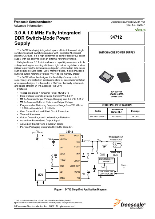
Document number: MC34712Rev. 4.0, 5/2007Freescale Semiconductor Advance Information* This document contains certain information on a new product.Specifications and information herein are subject to change without notice.© Freescale Semiconductor, Inc., 2007. All rights reserved.3.0 A 1.0 MHz Fully Integrated DDR Switch-Mode Power SupplyThe 34712 is a highly integrated, space efficient, low cost, single synchronous buck switching regulator with integrated N-channel power MOSFETs. It is a high performance point-of-load (PoL) power supply with the ability to track an external reference voltage.Its high efficient 3.0 A sink and source capability combined with its voltage tracking/sequencing ability and tight output regulation, makes it ideal to provide the termination voltage (V TT ) for modern data buses such as Double-Data-Rate (DDR) memory buses. It also provides a buffered output reference voltage (V REF ) to the memory chipset The 34712 offers the designer the flexibility of many control,supervisory, and protection functions to allow for easy implementation of complex designs. It is housed in a Pb-Free, thermally enhanced, and space efficient 24-Pin Exposed Pad QFN.Features•45 m Ω Integrated N-Channel Power MOSFETs •Input Voltage Operating Range from 3.0 V to 6.0 V•±1 % Accurate Output Voltage, Ranging from 0.7 V to 1.35 V •±1 % Accurate Buffered Reference Output Voltage•Programmable Switching Frequency Range from 200 kHz to 1.0 MHz with a default of 1.0 MHz•Over Current Limit and Short Circuit Protection •Thermal Shutdown•Output Overvoltage and Undervoltage Detection •Active Low Power Good Output Signal •Active Low Standby and Shutdown Inputs•Pb-Free Packaging Designated by Suffix Code EP.Figure 1. 34712 Simplified Application DiagramSWITCH-MODE POWER SUPPLYEP SUFFIX 98ARL10577D 24-PIN QFN34712ORDERING INFORMATIONDevice Temperature Range (T A )Package MC34712EP/R2-40 to 85°C24 QFNV INMCUPVINVREFINVIN VDDI FREQ GND SDSTBYBOOTSWVOUT INV COMP VREFOUTPGND PGDDR MEMORY CONTROLER34712V DDQDDR MEMORY CHIPSET V INV REFV TTV DDQV DDQMEMORY BUSTERMINATING RESISTORS(3.0V TO 6.0V)INTERNAL BLOCK DIAGRAMINTERNAL BLOCK DIAGRAMFigure 2. 34712 Simplified Internal Block Diagram34712Analog Integrated Circuit Device DataAnalog Integrated Circuit Device Data 34712PIN CONNECTIONSPIN CONNECTIONSFigure 3. 34712 Pin ConnectionsTable 1. 34712 Pin DefinitionsA functional description of each pin can be found in the Functional Pin Description section beginning onpage 10.Pin NumberPin Name Pin Function Formal Name Definition1GND Ground Signal GroundAnalog signal ground of IC2FREQ Passive Frequency Adjustment Buck converter switching frequency adjustment pin3NC None No Connect No internal connections to this pin4PG Output Power Good Active-low (open drain) power-good status reporting pin 5STBY Input Standby Standby mode input control pin 6SDInput Shutdown Shutdown mode input control pin 7VREFIN Input Voltage-Tracking-Reference Input Voltage-Tracking-Reference voltage input8VREFOUTOutput Reference VoltageOutput Buffered output equal to 1/2 of voltage-tracking reference 9COMPPassive Compensation Buck converter external compensation network pin 10INV Input Error Amplifier Inverting Input Buck converter error amplifier inverting input pin11VOUT Output Output Voltage Discharge FET Discharge FET drain connection (connect to buck converter output capacitors)12,13,14PGND Ground Power Ground Ground return for buck converter and discharge FET 15,16,17SW Power Switching Node Buck converter power switching node 18,19,20PVIN Supply Power-Circuit SupplyInputBuck converter main supply voltage input21BOOTPassiveBootstrapBootstrap switching node (connect to bootstrap capacitor)GND FREQ STBY PG NC SDV R E F I NC O M PI N VV O U TP G N DSW P V I NB O O TV I NV D D IV R E F O U TPGND PGNDSW SWPVIN P V I NV I NAnalog Integrated Circuit Device Data34712PIN CONNECTIONS22,23VINSupply Logic-Circuit SupplyInput Logic circuits supply voltage input24VDDIPassiveInternal Voltage RegulatorInternal Vdd Regulator (connect filter capacitor to this pin)Table 1. 34712 Pin Definitions (continued)A functional description of each pin can be found in the Functional Pin Description section beginning on page 10.Pin NumberPin NamePin FunctionFormal Name DefinitionAnalog Integrated Circuit Device Data 34712ELECTRICAL CHARACTERISTICSMAXIMUM RATINGSELECTRICAL CHARACTERISTICSMAXIMUM RATINGSTable 2. Maximum RatingsAll voltages are with respect to ground unless otherwise noted. Exceeding these ratings may cause a malfunction or permanent damage to the device.RatingsSymbolValueUnitELECTRICAL RATINGS Input Supply Voltage (VIN) PinV IN -0.3 to 7.0V High-Side MOSFET Drain Voltage (PVIN) Pin PV IN -0.3 to 7.0V Switching Node (SW) PinV SW -0.3 to 7.5V BOOT Pin (Referenced to SW Pin)V BOOT - V SW-0.3 to 7.5V PG, VOUT, SD, and STBY Pins--0.3 to 7.0V VDDI, FREQ, INV, COMP, VREFIN, and VREFOUT Pins --0.3 to 3.0V Continuous Output Current (1)I OUT±3.0AESD Voltage (2)Human Body Model Device Charge Model (CDM)V ESD1V ESD3±2000±750VTHERMAL RATINGSOperating Ambient Temperature (3)T A -40 to 85°C Storage TemperatureT STG -65 to +150°C Peak Package Reflow Temperature During Reflow (4), (5)T PPRT Note 5°C Maximum Junction Temperature T J(MAX)+150°C Power Dissipation (T A = 85 °C) (6)P D2.9WNotes1.Continuous output current capability so long as T J is ≤ T J(MAX).2.ESD1 testing is performed in accordance with the Human Body Model (C ZAP = 100 pF, R ZAP = 1500 Ω), ESD3 testing is performed inaccordance with the Charge Device Model (CDM).3.The limiting factor is junction temperature, taking into account power dissipation, thermal resistance, and heatsinking.4.Pin soldering temperature limit is for 10 seconds maximum duration. Not designed for immersion soldering. Exceeding these limits maycause malfunction or permanent damage to the device.5.Freescale’s Package Reflow capability meets Pb-free requirements for JEDEC standard J-STD-020C. For Peak Package ReflowTemperature and Moisture Sensitivity Levels (MSL),Go to , search by part number [e.g. remove prefixes/suffixes and enter the core ID to view all orderable parts. (i.e. MC33xxxD enter 33xxx), and review parametrics.6.Maximum power dissipation at indicated ambient temperature.Analog Integrated Circuit Device Data34712ELECTRICAL CHARACTERISTICS MAXIMUM RATINGSTHERMAL RESISTANCE (7)Thermal Resistance, Junction to Ambient, Single-Layer Board (1s) (8)R θJA 139°C/W Thermal Resistance, Junction to Ambient, Four-Layer Board (2s2p) (9)R θJMA 43°C/W Thermal Resistance, Junction to Board (10)R θJB22°C/WNotes7.The PVIN, SW, and GND pins comprise the main heat conduction paths.8.Per SEMI G38-87 and JEDEC JESD51-2 with the single-layer board (JESD51-3) horizontal.9.Per JEDEC JESD51-6 with the board (JESD51-7) horizontal. There are no thermal vias connecting the package to the two planes in theboard.10.Thermal resistance between the device and the printed circuit board per JEDEC JESD51-8. Board temperature is measured on the topsurface of the board near the package.Table 2. Maximum Ratings (continued)All voltages are with respect to ground unless otherwise noted. Exceeding these ratings may cause a malfunction or permanent damage to the device.RatingsSymbolValueUnitAnalog Integrated Circuit Device Data 34712ELECTRICAL CHARACTERISTICSSTATIC ELECTRICAL CHARACTERISTICSSTATIC ELECTRICAL CHARACTERISTICSTable 3. Static Electrical CharacteristicsCharacteristics noted under conditions 3.0 V ≤ V IN ≤ 6.0 V, - 40°C ≤ T A ≤ 85°C, GND = 0 V unless otherwise noted. Typical values noted reflect the approximate parameter means at T A = 25°C under nominal conditions unless otherwise noted.CharacteristicSymbolMinTypMaxUnitIC INPUT SUPPLY VOLTAGE (VIN) Input Supply Voltage Operating Range V IN 3.0- 6.0VInput DC Supply Current (11)Normal Mode: SD = 1 & STBY = 1, Unloaded Outputs I IN --25mAInput DC Supply Current (11)Standby Mode, SD = 1 & STBY = 0I INQ --15mAInput DC Supply Current (11)Shutdown Mode, SD = 0 & STBY = XI INOFF--100µAINTERNAL SUPPLY VOLTAGE OUTPUT (VDDI)Internal Supply Voltage RangeV DDI2.352.52.65VBUCK CONVERTER (PVIN, SW, GND, BOOT, INV, COMP)High-side MOSFET Drain Voltage Range P VIN 2.5- 6.0V Output Voltage Adjustment Range (12)V OUT 0.7- 1.35V Output Voltage Accuracy (12), (13), (14)--1.0- 1.0%Line Regulation (12)Normal Operation, V IN = 3.0 V to 6.0 V, I OUT = ±3.0 A REG LN -1.0- 1.0%Load Regulation (12)Normal Operation, I OUT = -3.0 A to 3.0 AREG LD-1.0- 1.0%Error Amplifier Common Mode Voltage Range (12), (15)V REF0.0- 1.35V Output Undervoltage Threshold V UVR -1.5--8.0%Output Overvoltage Threshold V OVR 1.5-8.0%Continuous Output CurrentI OUT -3.0- 3.0A Over Current Limit, Sinking and Sourcing I LIM - 4.0-A Short Circuit Current Limit (Sourcing and Sinking)I SHORT -6.5-AHigh-Side N-CH Power MOSFET (M3) R DS(ON) (12)I OUT = 1.0 A, V BOOT - V SW = 3.3 VR DS(ON)HS 10-45m ΩLow-Side N-CH Power MOSFET (M4) R DS(ON) (12)I OUT = 1.0 A, V IN = 3.3 V R DS(ON)LS10-45m ΩNotes 11.See section “MODES OF OPERATION”, page 14 has a detailed description of the different operating modes of the 3471212.Design information only, this parameter is not production tested.13.±1% is assured at room temperature.14.Overall output accuracy is directly affected by the accuracy of the external feedback network, 1% feedback resistors are recommended.15.The 1% output voltage regulation is only guaranteed for a common mode voltage range greater than or equal to 0.7V at room temperature.Analog Integrated Circuit Device Data34712ELECTRICAL CHARACTERISTICSSTATIC ELECTRICAL CHARACTERISTICSM2 R DS(ON)(V IN = 3.3 V, M2 is on)R DS(ON)M21.5- 4.0ΩPVIN Pin Leakage Current (Standby and Shutdown Modes)I PVIN -10-10µA INV Pin Leakage Current I INV -1.0- 1.0µA Thermal Shutdown Threshold (16)T SDFET -170-°C Thermal Shutdown Hysteresis (16)T SDHYFET-25-°COSCILLATOR (FREQ)Oscillator Frequency Adjusting Reference Voltage Range V FREQ0.0-V DDIVTRACKING (VREFIN, VREFOUT, VOUT)VREFIN External Reference Voltage Range (16)V REFIN 0.0- 2.7V VREFOUT Buffered Reference Voltage Range V REFOUT0.0- 1.35V VREFOUT Buffered Reference Voltage Accuracy (17)--1.0- 1.0%VREFOUT Buffered Reference Voltage Current Capability I REFOUT 0.0-8.0mA VREFOUT Buffered Reference Voltage Over Current Limit I REFOUTLIM -11-mA VREFOUT Total Discharge Resistance (16)R TDR(M6)-50-ΩVOUT Total Discharge Resistance (16)R TDR(M5)-50-ΩVOUT Pin Leakage Current (Standby Mode, V OUT = 3.6 V)I VOUTLKG-1.0- 1.0µACONTROL AND SUPERVISORY (STBY, SD, PG)STBY High Level Input Voltage V STBYHI 2.0--V STBY Low Level Input Voltage V STBYLO --0.4V STBY Pin Internal Pull Up Resistor R STBYUP 1.0- 2.0M ΩSD High Level Input Voltage V SDHI 2.0--V SD Low Level Input Voltage V SDLO --0.4V SD Pin Internal Pull Up Resistor R SDUP 1.0- 2.0M ΩPG Low Level Output Voltage (I PG = 3.0 mA)V PGLO --0.4VPG Pin Leakage Current (M1 is off, Pulled up to VIN)I PGLKG-1.0- 1.0µANotes16.Design information only, this parameter is not production tested.17.The 1 % accuracy is only guaranteed for V REFOUT greater than or equal to 0.7 V at room temperature.Table 3. Static Electrical CharacteristicsCharacteristics noted under conditions 3.0 V ≤ V IN ≤ 6.0 V, - 40°C ≤ T A ≤ 85°C, GND = 0 V unless otherwise noted. Typical values noted reflect the approximate parameter means at T A = 25°C under nominal conditions unless otherwise noted.CharacteristicSymbol Min Typ Max UnitAnalog Integrated Circuit Device Data 34712ELECTRICAL CHARACTERISTICSDYNAMIC ELECTRICAL CHARACTERISTICSDYNAMIC ELECTRICAL CHARACTERISTICSTable 4. Dynamic Electrical CharacteristicsCharacteristics noted under conditions 3.0 V ≤ V IN ≤ 6.0 V, - 40°C ≤ T A ≤ 85°C, GND = 0 V unless otherwise noted. Typical values noted reflect the approximate parameter means at T A = 25°C under nominal conditions unless otherwise noted.CharacteristicSymbolMinTypMaxUnitBUCK CONVERTER (PVIN, SW, GND, BOOT)Switching Node (SW) Rise Time (19)(P VIN = 3.3 V, I OUT = ±3.0 A)t RISE -14-nsSwitching Node (SW) Fall Time (19)(P VIN = 3.3 V, I OUT = ±3.0 A)t FALL -20-nsSoft Start Duration (Normal Mode)t SS 1.3- 2.6ms Over Current Limit Timert LIM -10-ms Over Current Limit Retry Time-out Periodt TIMEOUT 80-120ms Output Undervoltage/Overvoltage Filter Delay Timer t FILTER5.0-25µsOSCILLATOR (FREQ)Oscillator Default Switching Frequency (18)(FREQ = GND)F SW - 1.0-MHz Oscillator Switching Frequency RangeF SW200-1000kHzCONTROL AND SUPERVISORY (STBY, SD, PG)PG Reset Delayt PGRESET 8.0-12ms Thermal Shutdown Retry Time-out Period (19)t TIMEOUT80-120msNotes18.Oscillator Frequency tolerance is ±10%.19.Design information only, this parameter is not production tested.Analog Integrated Circuit Device Data34712FUNCTIONAL DESCRIPTION INTRODUCTIONFUNCTIONAL DESCRIPTIONINTRODUCTIONIn modern microprocessor/memory applications, address commands and control lines require system level termination to a voltage (V TT ) equal to 1/2 the memory supply voltage (V DDQ ). Having the termination voltage at midpoint, the power supply insures symmetry for switching times. Also, areference voltage (V REF ) that is free of any noise or voltage variations is needed for the DDR SDRAM input receiver, V REF is also equal to 1/2 V DDQ . Varying the V REF voltage will effect the setup and hold time of the memory. To comply with DDR requirements and to obtain best performance, V TT and V REF need to be tightly regulated to track 1/2 V DDQ across voltage, temperature, and noise margins. V TT should track any variations in the DC V REF value (V TT = V REF +/- 40 mV), (See Figure 4) for a DDR system level diagram.The 34712 supplies the V TT and a buffered V REF output. To ensure compliance with DDR specifications, the V DDQ line is applied to the VREFIN pin and divided by 2 internally through a precision resistor divider. This internal voltage is then used as the reference voltage for the V TT output. The same internal voltage is also buffered to give the V REFvoltage at the VREFOUT pin for the application to use without the need for an external resistor divider. The 34712 provides the tight voltage regulation and power sequencing/tracking required along with handling the DDR peak transient current requirements. Buffering the V REF output helps its immunity against noise and load changes.The 34712 utilizes a voltage mode synchronous buck switching converter topology with integrated low R DS(ON) (45 m Ω) N-channel power MOSFETs to provide a V TT voltage with an accuracy of less than ±2.0 %. It has a programmable switching frequency that allows for flexibility and optimization over the operating conditions and can operate at up to1.0 MHz to significantly reduce the external components size and cost. The 34712 can sink and source up to 3.0 A ofcontinuous current. It provides protection against output over current, overvoltage, undervoltage, and overtemperature conditions. It also protects the system from short circuitevents. It incorporates a power-good output signal to alert the host when a fault occurs.For boards that support the Suspend-To-RAM (S3) and the Suspend-To-Disk (S5) states, the 34712 offers the STBY and the SD pins respectively. Pulling any of these pins low, puts the IC in the corresponding state.By integrating the control/supervisory circuitry along with the Power MOSFET switches for the buck converter into a space-efficient package, the 34712 offers a complete, small-size, cost-effective, and simple solution to satisfy the needs of DDR memory applications.Besides DDR memory termination, the 34712 can be used to supply termination for other active buses and graphics card memory. It can be used in Netcom/Telecom applications like servers. It can also be used in desktop motherboards, game consoles, set top boxes, and high end high definition TVs.Figure 4. DDR System Level DiagramFUNCTIONAL PIN DESCRIPTIONREFERENCE VOLTAGE INPUT (VREFIN)The 34712 will track 1/2 the voltage applied at this pin.REFERENCE VOLTAGE OUTPUT (VREFOUT)This is a buffered reference voltage output that is equal to 1/2 V REFIN . It has a 10.0 mA current drive capability. This output is used as the V REF voltage rail and should be filtered against any noise. Connect a 0.1 µF, 6 V low ESR ceramic filter capacitor between this pin and the GND pin andbetween this pin and V DDQ rail. V REFOUT is also used as the reference voltage for the buck converter error amplifier.FREQUENCY ADJUSTMENT INPUT (FREQ)The buck converter switching frequency can be adjusted by connecting this pin to an external resistor divider between VDDI and GND pins. The default switching frequency (FREQ pin connected to ground, GND) is set at 1.0 MHz.SIGNAL GROUND (GND)Analog ground of the IC. Internal analog signals are referenced to this pin voltage.V DDQV DDQV TTV REFBUSDDR Memory Controller DDR Memory Input ReceiverR SR TFUNCTIONAL DESCRIPTION FUNCTIONAL PIN DESCRIPTIONINTERNAL SUPPLY VOLTAGE OUTPUT (VDDI) This is the output of the internal bias voltage regulator. Connect a 1.0 µF, 6 V low ESR ceramic filter capacitor between this pin and the GND pin. Filtering any spikes on this output is essential to the internal circuitry stable operation.OUTPUT VOLTAGE DISCHARGE PATH (VOUT) Output voltage of the Buck Converter is connected to this pin. it only serves as the output discharge path once the SD signal is asserted.ERROR AMPLIFIER INVERTING INPUT (INV) Buck converter error amplifier inverting input. Connect the VTT voltage directly to this pin.COMPENSATION INPUT (COMP)Buck converter external compensation network connects to this pin. Use a type III compensation network.INPUT SUPPLY VOLTAGE (VIN)IC power supply input voltage. Input filtering is required for the device to operate properly.POWER GROUND (PGND)Buck converter and discharge MOSFETs power ground. It is the source of the buck converter low-side power MOSFET. SWITCHING NODE (SW)Buck converter switching node. This pin is connected to the output inductor.POWER INPUT VOLTAGE (PVIN)Buck converter power input voltage. This is the drain of the buck converter high-side power MOSFET. BOOTSTRAP INPUT (BOOT)Bootstrap capacitor input pin. Connect a capacitor (as discussed on page 19) between this pin and the SW pin to enhance the gate of the high-side Power MOSFET during switching.SHUTDOWN INPUT (SD)If this pin is tied to the GND pin, the device will be in Shutdown Mode. If left unconnected or tied to the VIN pin, the device will be in Normal Mode. The pin has an internal pull up of 1.5 MΩ. This input accepts the S5 (Suspend-To-Disk) control signal.STANDBY INPUT (STBY)If this pin is tied to the GND pin, the device will be in Standby Mode. If left unconnected or tied to the VIN pin, the device will be in Normal Mode. The pin has an internal pull up of 1.5 MΩ. This input accepts the S3 (Suspend-To-RAM) control signal.POWER GOOD OUTPUT SIGNAL (PG)This is an active low open drain output that is used to report the status of the device to a host. This output activates after a successful power up sequence and stays active as long as the device is in normal operation and is not experiencing any faults. This output activates after a 10 ms delay and must be pulled up by an external resistor to a supply voltage (e.g.,V IN.).FUNCTIONAL DESCRIPTIONFUNCTIONAL INTERNAL BLOCK DESCRIPTIONFUNCTIONAL INTERNAL BLOCK DESCRIPTIONFigure 5. 34712 Internal Block DiagramINTERNAL BIAS CIRCUITSThis block contains all circuits that provide the necessary supply voltages and bias currents for the internal circuitry. It consists of:•Internal Voltage Supply Regulator: This regulator supplies the V DDI voltage that is used to drive the digital/ analog internal circuits. It is equipped with a Power-On-Reset (POR) circuit that watches for the right regulation levels. External filtering is needed on the VDDI pin. This block will turn off during the shutdown mode.•Internal Bandgap Reference Voltage: This supplies the reference voltage to some of the internal circuitry.•Bias Circuit: This block generates the bias currents necessary to run all of the blocks in the IC. SYSTEM CONTROL AND LOGICThis block is the brain of the IC where the device processes data and reacts to it. Based on the status of the STBY and SD pins, the system control reacts accordingly and orders the device into the right status. It also takes inputs from all of the monitoring/protection circuits and initiates power up or power down commands. It communicates with the buck converter to manage the switching operation and protects it against any faults.OSCILLATORThis block generates the clock cycles necessary to run the IC digital blocks. It also generates the buck converter switching frequency. The switching frequency has a default value of 1.0 MHz and can be programmed by connecting a resistor divider to the FREQ pin, between VDDI and GND pins (See Figure 1).PROTECTION FUNCTIONSThis block contains the following circuits:•Over Current Limit and Short Circuit Detection: This block monitors the output of the buck converter for over current conditions and short circuit events and alerts the system control for further command.•Thermal Limit Detection: This block monitors the temperature of the device for overheating events. If the temperature rises above the thermal shutdownthreshold, this block will alert the system control forfurther commands.•Output Overvoltage and Undervoltage Monitoring: This block monitors the buck converter output voltage toensure it is within regulation boundaries. If not, thisblock alerts the system control for further commands.CONTROL AND SUPERVISORY FUNCTIONS This block is used to interface with an outside host. It contains the following circuits:•Standby Control Input: An outside host can put the 34712 device into standby mode (S3 or Suspend-To-RAM mode) by sending a logic “0” to the STBY pin.•Shutdown Control Input: An outside host can put the 34712 device into shutdown mode (S5 or Suspend-To-Disk mode) by sending a logic “0” to the SD pin.•Power Good Output Signal PG: The 34712 can communicate to an external host that a fault hasInternal Bias System ControlOscillator Circuits& LogicControl &Protection Tracking &SupervisoryFunctionsFunctionsSequencingBuck ConverterFUNCTIONAL DESCRIPTION FUNCTIONAL INTERNAL BLOCK DESCRIPTIONoccurred by releasing the drive on the PG pin high,allowing the signal/pin to be pulled high by the external pull-up resistor.TRACKING AND SEQUENCINGThis block allows the output of the 34712 to track 1/2 the voltage applied at the VREFIN pin. This allows the V REF and V TT voltages to track 1/2 V DDQ and assures that none of them will be higher than V DDQ at any point during normal operating conditions. For power down during a shutdown (S5) mode, the 34712 uses internal discharge MOSFETs (M5 and M6 on Figure 2) to discharge V TT and V REF respectively. These discharge MOSFETs are only active during shutdown mode. Using this block along with controlling the SD and STBY pins can offer the user power sequencing capabilities by controlling when to turn the 34712 outputs on or off.BUCK CONVERTERThis block provides the main function of the 34712: DC to DC conversion from an un-regulated input voltage to a regulated output voltage used by the loads for reliable operation. The buck converter is a high performance, fixed frequency (externally adjustable), synchronous buck PWM voltage-mode control. It drives integrated 45 mΩ N-channel power MOSFETs saving board space and enhancing efficiency. The switching regulator output voltage is adjustable with an accuracy of less than ±2.0 % to meet DDR requirements. Its output has the ability to track 1/2 the voltage applied at the VREFIN pin. The regulator's voltage control loop is compensated using a type III compensation network, with external components to allow for optimizing the loop compensation, for a wide range of operating conditions. A typical Bootstrap circuit with an internal PMOS switch is used to provide the voltage necessary to properly enhance the high-side MOSFET gate.The 34712 is designed to address DDR memory power supplies. The integrated converter has the ability to both sink and source up to 3.0 A of continuous current, making it suitable for bus termination power supplies.FUNCTIONAL DEVICE OPERATIONOPERATIONAL MODESFUNCTIONAL DEVICE OPERATIONOPERATIONAL MODESFigure 6. Operation Modes DiagramMODES OF OPERATIONThe 34712 has three primary modes of operation:Normal ModeIn normal mode, all functions and outputs are fully operational. To be in this mode, the V IN needs to be within its operating range, both Shutdown and Standby inputs are high, and no faults are present. This mode consumes the most amount of power.Standby ModeThis mode is predominantly used in Desktop memory solutions where the DDR supply is desired to be ACPI compliant (Advanced Configuration and Power Interface). When this mode is activated by pulling the STBY pin low, V TT is put in High Z state, I OUT = 0 A, and V REF stays active. This is the S3 state Suspend-To-Ram or Self Refresh mode and it is the lowest DRAM power state. In this mode, the DRAM will preserve the data. While in this mode, the 34712 consumes less power than in the normal mode, because the buck converter and most of the internal blocks are disabled.Shutdown ModeIn this mode, activated by pulling the SD pin low, the chip is in a shutdown state and the outputs are all disabled and discharged. This is the S4/S5 power state or Suspend-To-Disk state, where the DRAM will loose all of its data content (no power supplied to the DRAM). The reason to discharge the V TT and V REF lines is to ensure upon exiting, the Shutdown Mode that V TT and V REF are lower than V DDQ, otherwise V TT can remain floating high, and be higher than V DDQ upon powering up. In this mode, the 34712 consumes the least amount of power since almost all of the internal blocks are disabled.START-UP SEQUENCEWhen power is first applied, the 34712 checks the status of the SD and STBY pins. If the device is in a shutdown mode, no block will power up and the output will not attempt to ramp. If the device is in a standby mode, only the V DDI internal supply voltage and the bias currents are established and no further activities will occur. Once the SD and STBY pins are released to enable the device, the internal V DDI POR signal is also released. The rest of the internal blocks will be enabled。
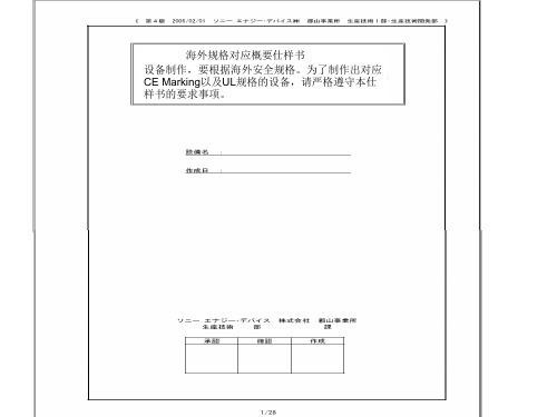
海外规格仕样书第4版(中文)
4.在机铭板上标示出以下内容 ・制造者名 ・制造年月 ・形式以及model编号 ・定格电源电压(电压、位相、周波数、最大负荷电流、etc) 在电源上不可以用「AC200V」表示,而要用「~200V」表示 ・气压(定格压力) ・原产地表示(MADE IN JAPAN等) 注)FA标准机铭板: 4—710—156—01(大—11) 带孔、by三立产业 EN60204 UL1740
8.盖子、马达框架、trans core、电装品筐体、以及接续管等的金属部, 如果和地线或金属接触,会导致和物品本身的导通。
EN60204、UL1740
7/28
要求事项
1.电源切断装置要使用得到认可的漏电断路器、自动断路器、线路保护器 EN60204、UL1740 2.主断路器的定格要遵循以下事项。 EN60204、UL1740 a)电流容量:最大负荷电流的115%以上,或者使用的导线的要求容许电流以下 (14配线以及电路——参照17) b)切断容量:在机器上使用的马达中,最大马达的 rotor rock电流+其他装置的 最大负荷电流以上 3.电力引入线(一次电源)要直接和断路器连接 EN60204、UL1740 4.电源切断装置遵循一下事项。 EN60204、UL1740 (a)安装把手,方便从外部操作 (b)把手的中心高度在0.6~1.9以内 (c)要有OFF锁定机能.(可以上锁的构造) (d)门关上时要有ON/OFF的明确指示 (e)ON/OFF可以用「O」也可以用「I」来表示 (f)接地导线以外所有的相要同时切断 (g)主断路器上如果没有OFF锁定机能,要在负荷侧设定带钥匙的主开关。
贵社 check
本社 check
备注
① 外 观 以 及 构 造 的 规 定
4/28
GE Industrial Solutions iVB Intelligent Embeded Po

• GB1984-2003
<High-voltage alternating current circuit breaker>
• GB/T11022-1999
Intelligent and Compact
Intelligence
Bring you reliable power solution
VCB is the most critical component for MV Switchgear iVB integrates conveniently for you
<Common specifications for high-voltage switchgear and control gear standards>
• DL/T 402-2007
<High-voltage alternating current circuit breakers>
• DL/T 403-2000
T : +86 21 3877 7888
Printing Code: IN201301B26EN
F : +86 21 3877 7600
© Copyright GE Industrial Solutions 2013
iVB Intelligent Embeded Pole Vacuum Circuit Breaker
Aux. contact
iTU
iTU Intelligent relay protection
泰产品参数

双1,6-亚己基三胺五甲叉膦酸BHMTPMPA Bis(Hexamethylene Triamine Penta (Methylene PhosphonicAcid))BHMTPMPACAS No. 34690-00-1别名:二己烯三胺五亚甲基膦酸、二亚已基三胺五亚甲基磷酸分子式 C17H44O15N3P5相对分子质量:685 结构式一、性能与用途:BHMTPMPA是高效的螯合型阻垢剂,对碳酸盐垢和硫酸盐垢具有良好的阻垢效果。
BHMTPMPA在较宽的PHX围和120℃高温下有极佳的水溶性和热稳定性,对钙离子容忍度高。
BHMTPMPA用作油田水处理的缓蚀阻垢剂,工业循环冷却水和锅炉水的阻垢缓蚀剂。
二、技术指标项目指标外观深琥珀色液体活性组分% 43.0-48.0氯化物(以Cl-计)% ≤8.0Fe(以Fe2+计)含量mg/L65≤密度(20℃)g/cm3≥ 1.2pH(1%水溶液) ≤ 2.0三、使用方法单独使用或与聚羧酸型阻垢分散剂配合使用。
乙二胺四甲叉膦酸钠EDTMPSEthylene Diamine Tetra (Methylene Phosphonic Acid) Sodium CAS No. 1429-50-1别名:乙二胺四亚甲基膦酸钠、乙二胺四亚甲基磷酸、乙二胺四甲叉磷酸分子式 C6H12O12N2P4Na8相对分子质量:612.13 结构式一、性能与用途EDTMPS是含氮有机多元膦酸,属阴极型缓蚀剂,与无机聚磷酸盐相比,缓蚀率高3~5倍。
能与水混溶,无毒无污染,化学稳定性及耐温性好,在200℃下仍有良好的阻垢效果。
EDTMPS在水溶液中能离解成8个正负离子,因而可以与多个金属离子螯合,形成多个单体结构大分子网状络合物,松散地分散于水中,使钙垢正常结晶被破坏。
EDTMPS对硫酸钙、硫酸钡垢的阻垢效果好。
EDTMPS用于循环水和锅炉水的缓蚀阻垢剂、无氰电镀的络合剂、纺织印染行业螯合剂和氧漂稳定剂。
4 硝基邻苯二甲酰亚胺

计算化学数据
1.疏水参数计算参考值(XlogP):无 2.氢键供体数量:1 3.氢键受体数量:4 4.可旋转化学键数量:0 5.互变异构体数量:3 6.拓扑分子极性表面积92 7.重原子数量:14 8.表面电荷:0 9.复杂度:309 10.同位素原子数量:0 11.确定原子立构中心数量:0
急救措施
物理参数
熔点:206°C(lit.) 水溶解性:<0.01 g/100 mL at 18 ºC
用途说明
用作有机合成及荧光染料,颜料中间体。 贮存运输:阴凉干燥处保存
危险说明
危险代码:Xi 危险等级:RR36/37/38 安全等级:S26-37/39
分子结构数据
1、摩尔折射率:43.97 2、摩尔体积(m3/mol):119.3 3、等张比容(90.2K):348.1 4、表面张力(dyne/cm):72.2
急救: 对保护施救者的忠告: 将患者转移到安全的场所。咨询医生。出示此化学品安全技术说明书给到现场的医生看。
消防措施
灭火剂: 灭火注意事项及防护措施:
泄露应急处理
作业人员防护措施、防护装备和应急处置程序: 环境保护措施:
操作处置与储存
操作注意事项: 储存注意事项:
谢谢观看
4 硝基邻苯二甲酰亚胺
化学物质
01 性能描述
目录
02 物理参数
03 用途说明
04 危险说明
05 分子结构数据
06 计算化学数据
目录
07 急救措施
09 泄露应急处理
08 消防措施 010 操作处置与储存
4-硝基邻苯二甲酰亚胺是一种化学物质,分子式是C8H4N2O4。
性能描述
分子结构式外观描述:浅黄色粉末。
4-硝基苯甲醚(对硝基苯甲醚;对硝基茴香醚;对甲氧基硝基苯)的理化性质及危险特性表

对眼睛、粘膜及皮肤有刺激作用。可能引起贫血、紫绀、肝损害等。
燃爆危险
本品可燃,有毒,具刺激性。
急救
措施
皮肤接触:
脱去污染的衣着,用肥皂水和清水彻底冲洗皮肤。
眼睛接触:
提起眼睑,用流动清水或生理盐水冲洗。就医。
吸入:
迅速脱离现场至空气新鲜处。保持呼吸道通畅。如呼吸困难,给输氧。如呼吸停止,立即进行人工呼吸。就医。
储运注意事项
①操作注意事项:密闭操作,加强通风。操作人员必须经过专门培训,严格遵守操作规程。建议操作人员佩戴自吸过滤式防尘口罩,戴安全防护眼镜,穿防毒物渗透工作服,戴橡胶手套。远离火种、热源,工作场所严禁吸烟。使用防爆型的通风系统和设备。避免产生粉尘。避免与氧化剂、还原剂、酸类、碱类接触。搬运时要轻装轻卸,防止包装及容器损坏。配备相应品种和数量的消防器材及泄漏应急处理设备。倒空的容器可能残留有害物。
4-硝基苯甲醚的理化性质及危险特性表
标识
别名:
对硝基苯甲醚;对硝基茴香醚;对甲氧基硝基苯
危险货物编号:
61697
英文名:
4-nitroanisole
UN编号:
2730
CAS号:
100-17-4
分子式:
C7H7NO3
分子量:
153.14
理化性质
外观与性状:
无色结晶。
主要用途:
用作有机合成中间体。
熔点(℃):
54
相对密度(水=1):
1.23
沸点(℃):
274
相对蒸汽密度(空气=1):
无资料
闪点(℃):
无意义
饱和蒸汽压(k Pa):
无资料
引燃温度(℃):
无资料
安捷伦科技有限公司-苯胺蓝化学品安全技术说明书

Aniline Blue *************(24小时)化学品安全技术说明书GHS product identifier 应急咨询电话(带值班时间)::供应商/ 制造商:供应商/ 制造商: Agilent Technologies, Inc.(美国安捷伦科技有限公司)住所:5301 Stevens Creek Boulevard, Santa Clara, CA, 95051, United States 联系电话:+1 800 227 9770 供应商/ 制造商: Agilent Technologies Singapore (International) Pte Ltd.(安捷伦科技新加坡(国际)私人有限公司)住所:No. 1 Yishun Avenue 7, Singapore, 768923 联系电话:(65) 6276 2622供应商/ 制造商: Agilent Technologies Denmark ApS (安捷伦科技丹麦私人有限公司)住所:Produktionsvej 42, DK-2600 Glostrup, Denmark 联系电话: +45 44859500 苯胺蓝化学品的推荐用途和限制用途AR173部件号:安全技术说明书根据 GB/ T 16483-2008 和 GB/ T 17519-2013本安全技术说明书责任人的e-mail地址:***************GHS化学品标识:苯胺蓝推荐用途AR173 // Aniline Blue // Artisan Masson's Trichrome Stain Kit // 65 mL & 115 mL参考号码: SDS013:有关环境保护措施,请参阅第 12 节。
物质或混合物的分类根据 GB13690-2009 和 GB30000-2013紧急情况概述液体。
蓝色。
象醋 [轻微]如发生皮肤刺激: 求医要么就诊。
TO-263中文资料

Thermal Characteristics
Symbol
Parameter
RθJC RθJA
Thermal Resistance Junction to Case Max. Thermal Resistance Junction to Ambient Max.
Value
TO-263
1.7
TO-220AB
1.6
1.5
1.4
1.3
1.2
VGS=10V
VGS=15V
1.1
1.0
0.9
0.8 0 1 2 3 4 5 6 7 8 9 10 11 12 Drain Current-ID (A)
3 2 1
3-Lead Plastic TO-220FP Package Code: F Pin 1: Gate Pin 2: Drain Pin 3: Source
3 2 1
D
H06N60 Series
G
Symbol:
S
Absolute Maximum Ratings
Symbol
Parameter
Description
This high voltage MOSFET uses an advanced termination scheme to provide enhanced voltage-blocking capability without degratding performance over time. In addition, this advanced MOSFET is designed to withstand high energy in avalanche and commutation modes. The new energy efficient design also offers a drain-to-source diode with a fast recovery time. Designed for high voltage, high speed switching applications in power supplies, converters and PWM motor controls, these devices are particularly well suited for bridge circuits where diode speed and commutating safe operating areas are critical and offer additional and saafety margin against unexpected voltage transients.
四氯化碲化学品安全技术说明书

化学品安全技术说明书产品名称: 四氯化碲按照GB/T 16483、GB/T 17519 编制修订日期:最初编制日期:版本:第1部分化学品及企业标识化学品中文名:四氯化碲化学品英文名:Tellurium(IV) Chloride (Metals Basis)企业名称:企业地址:传真:联系电话:企业应急电话:产品推荐及限制用途:For industry use only.。
第2部分危险性概述紧急情况概述:造成严重皮肤灼伤和眼损伤。
GHS危险性类别:皮肤腐蚀/ 刺激类别1B标签要素:象形图:警示词:危险危险性说明:H314 造成严重皮肤灼伤和眼损伤。
防范说明:•预防措施:•P260 不要吸入粉尘/烟/气体/烟雾/蒸气/喷雾。
•P264 作业后彻底清洗。
•P280 戴防护手套/穿防护服/戴防护眼罩/戴防护面具。
•事故响应:•P301+P330+P331 如误吞咽:漱口。
不要诱导呕吐。
•P303+P361+P353 如皮肤(或头发)沾染:立即脱掉所有沾染的衣服。
用水清洗皮肤/淋浴。
•P363 沾染的衣服清洗后方可重新使用。
•P304+P340 如误吸入:将人转移到空气新鲜处,保持呼吸舒适体位。
•P310 立即呼叫解毒中心/医生•P321 具体治疗 ( 见本标签上的…… )。
•P305+P351+P338 如进入眼睛:用水小心冲洗几分钟。
如戴隐形眼镜并可方便地取出,取出隐形眼镜。
继续冲洗。
•安全储存:•P405 存放处须加锁。
•废弃处置:•P501 按当地法规处置内装物/容器。
物理和化学危险:无资料健康危害:造成严重皮肤灼伤和眼损伤。
环境危害:无资料第3部分成分/组成信息第4部分急救措施急救:吸入: 如果吸入,请将患者移到新鲜空气处。
皮肤接触: 脱去污染的衣着,用肥皂水和清水彻底冲洗皮肤。
如有不适感,就医。
眼晴接触: 分开眼睑,用流动清水或生理盐水冲洗。
立即就医。
食入: 漱口,禁止催吐。
立即就医。
对保护施救者的忠告:将患者转移到安全的场所。
BL21-CodonPlus-RP Competent Cells, Part Number 230
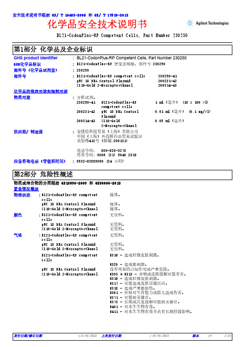
BL21-CodonPlus-RP Competent Cells, Part Number 230250*************(24小时)化学品安全技术说明书GHS product identifier 应急咨询电话(带值班时间)::供应商/ 制造商:安捷伦科技贸易(上海)有限公司中国(上海)外高桥自由贸易试验区英伦路412号(邮编:200131)电话号码: 800-820-3278传真号码: 0086 (21) 5048 2818BL21-CodonPlus-RP Competent Cells, Part Number 230250化学品的推荐用途和限制用途BL21-CodonPlus-RP competent cells 230250-41pUC 18 DNA Control Plasmid 200231-42XL10-Gold 2-Mercaptoethanol 200314-43部件号:物质用途:分析试剂。
230250-41BL21-CodonPlus-RP competent cells1 ml(毫升) (10 x 100 µl)200231-42pUC 18 DNA ControlPlasmid0.01 ml(毫升) (0.1 ng/µl)200314-43XL10-Gold2-Mercaptoethanol0.05 ml(毫升)部件号(化学品试剂盒):230250安全技术说明书根据 GB/ T 16483-2008 和 GB/ T 17519-2013GHS化学品标识:BL21-CodonPlus-RP 感受态细胞,部件号 230250物质或混合物的分类根据 GB13690-2009 和 GB30000-2013紧急情况概述BL21-CodonPlus-RP competent cells液体。
pUC 18 DNA Control Plasmid 液体。
二乙烯三胺标准物质

二乙烯三胺标准物质
二乙烯三胺(CAS号:111-40-0)是一种有机化合物,化学式为C4H13N3,分子量为115.17。
它是无色液体,具有强碱性。
二乙烯三胺主要用作金属离子的螯合剂和氧化还原过程中电子传递的中间体。
此外,它还广泛应用于催化剂、阻燃剂、表面活性剂等领域。
二乙烯三胺的生产工艺较为复杂,一般采用化工合成的方法如烟碱催化还原法或溶剂萃取法。
在实验室中,二乙烯三胺可作为标准物质用于定量分析与质谱分析等研究中。
使用时需注意其强碱性和毒性,遵守相关安全操作规程。
1734452-2资料

1734452-2 Product DetailsHome | Customer Support | Suppliers | Site Map | Privacy Policy | Browser Support© 2008 Tyco Electronics Corporation All Rights Reserved SearchProducts Documentation Resources My Account Customer SupportHome > Products > By Type > Removable Memory Products > Product Feature Selector > Product Details1734452-2Active Removable Memory ProductsAlways EU RoHS/ELV Compliant (Statement of Compliance)Product Highlights:?Format = CompactFlash™?CompactFlash™ Product Type =Ejector Assembly?Header Type = Type II?Tray?Region = AmericasView all Features | Find SimilarProductsCheck Pricing &AvailabilitySearch for ToolingProduct FeatureSelectorContact Us AboutThis ProductQuick LinksDocumentation & Additional InformationProduct Drawings:?EJECTOR ASSE'Y FOR COMPACT FLASH HEADER(PDF, English)Catalog Pages/Data Sheets:?None AvailableProduct Specifications:?None AvailableApplication Specifications:?None AvailableInstruction Sheets:?None AvailableCAD Files: (CAD Format & Compression Information)?2D Drawing (DXF, Version O)?3D Model (IGES, Version O)?3D Model (STEP, Version O)List all Documents Related Products: ?ToolingProduct Features (Please use the Product Drawing for all design activity)Product Type Features:?Cover Material = Stainless SteelBody Related Features:?CompactFlash™ Product Type = EjectorAssembly?Header Type = Type II?Push Button Color = Black?Push Button Flammability Rating = UL 94V-0 ?Push Button Material = ThermoplasticContact Related Features:?Region = Americas Industry Standards:?RoHS/ELV Compliance = RoHS compliant, ELVcompliant?Lead Free Solder Processes = Not relevant forlead free process?RoHS/ELV Compliance History = Always wasRoHS compliantConditions for Usage:?Format = CompactFlash™Packaging Related Features:?Packaging Method = TrayOther:?Brand = AMPProvide Website Feedback | Contact Customer Support。
Modesto 4-pcs. cookware set 产品说明书
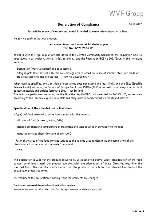
Declaration of Compliancefor articles made of ceramic and metal intended to come into contact with food06.11.2017Hereby we confirm that our product:Item name: 4-pcs. cookware set Modesto w. panItem No.: 0021.2904.12complies with the legal regulations laid down in the German Commodity Ordinance,the Regulation (EC)No 1935/2004,in particular Article 3,11(5),15and 17,and the Regulation (EC)No 2023/2006,in their relevant versions.When used as specified,the transition of substances does not exceed the legal limits and the SRLs (Specific Release Limits)according to Council of Europe Resolution CM/Res(2013)9on metals and alloys used in food contact materials and articles (effective 2013–1st Edition).The tests are performed according to the Directive 84/500/EEC,last amended by 2005/31/EC,respectively according to the …Technical guide on metals and alloys used in food contact materials and articles “.Specification of the intended use or limitations:- Type(s) of food intended to come into contact with the material:- Intended duration and temperature of treatment and storage while in contact with the food:- Ratio of the area of the food contact surface to the volume used to determine the compliance of the food contact material or article made from metal:This declaration is valid for the product delivered by us as specified above.Under consideration of the food contact conditions stated,the product complies with the stipulations of these Directives regarding the specified foods.The user shall verify himself that the product is suitable for the intended food beyond the stipulations of the Directives.The validity of the declaration is ending if the requirements are changed.This document was created electronically and is valid without signature.Name of the document: L01_0021.2904.12_EN_20171106_4-pcs. cookware set Modesto w. pan_kl.pdf Silargan pots (special steel with ceramic coating) with chromed rim made of stainless steel, pan made of stainless steel with ceramic coating Item no. 21.0929.6737Description (material/optics)/ analogue items :repeated contact, short-time also above 100°C12,6all types of food (aqueous, acidic, fatty)WMF Group - a Group SEB company WMF Group GmbHVORSITZENDER DES AUFSICHTSRATES SITZ DER GESELLSCHAFT BANKVERBINDUNG Eberhardstraße 35Bertrand Neuschwander Geislingen | Steige Commerzbank AG Göppingen 73312 Geislingen | SteigeRECHTSFORM IBAN DE06 6104 0014 0160 3000 00GermanyGESCHÄFTSFÜHRER Gesellschaft mit beschränkter Haftung BIC COBADEFFXXX Dr. Volker Lixfeld | VORSITZENDER REGISTERGERICHT telefon+49 7331 25 1Bernd Stoeppel Amtsgericht Ulm HRB 732253fax+49 7331 45 387 WEEE-Reg.-Nr. DE 78426351 USt.-ID.-Nr. DE 298 927 552email****************** St.-Nr. 62050|01224web GLN 4000530 00000 2。
“在邦”四钼酸铵产品说明书

“在邦”四钼酸铵产品说明书一.产品物性:产品名称:四钼酸铵(产品型号:ZBM57,品牌:在邦)英文名:Ammoinum Tetramolybdate别名:(T-4)-钼酸铵,钼酸铵分子式:H8MoN2O4;(NH4)2MoO4分子量:663.9外观:为白色或微黄色粉末可溶性:在水、普通矿物酸中微溶,易溶于碱,不溶于醇和丙酮。
相对密度:0.6-1.4g/cm3CAS号:13106-76-8RTECS号:QA4900000二.产品用途:1.要用于染料、颜料,是制取钼粉、微量元素肥料、制造陶瓷颜料及其它钼化合物的原料。
2.石化工业用作催化剂,冶金工业用于制钼粉、钼条、钼丝、钼坯、钼片等,亦可作为微量无素肥料,制造陶瓷色料、颜料及其它钼的化合物的原料。
3.用作颜料、色淀和织物阻燃防火剂,是制备钼制品的主要原料。
4.用于粉末冶金、高纯三氧化钼及其他钼化学品的原料。
5.是测定磷的重要试剂,也是生产丙烯腈催化剂的最佳材料,也用于照相等。
6.用作分析试剂,也用于陶器釉彩的配制。
三.技术指标:四.产品标准:五.注意事项:1.不能与粮食、食物、种子、饲料、各种日用品混装、混运;2.操作现场不得吸烟、饮水、进食;3.搬运时要装轻卸,防止包装及容器损坏;4.分装和搬运作业要注意个人防护。
皮肤接触:用肥皂水或清水彻底冲洗,就医;5.眼睛接触:拉开眼睑,用流动清水冲洗15分钟,就医;。
6.吸入:脱离现场至空气新鲜处,就医;7.食入:误服者,饮适量温水,催吐,就医;8.工程控制:严加密封,提供充分的局部排风;9.呼吸系统防护:作业工人佩戴防毒口罩。
必要时佩戴自给式呼吸器;10.眼睛防护:戴化学安全防护眼镜;11.防护服:穿相应的防护服;12.手防护:戴防化学品手套;13.工作后,淋浴更衣。
注意个人清洁卫生。
六.三废处理:1.泄露处置:隔离泄露污染区,周围设警告标志,建议应急处理人员戴自给式呼吸器,穿化学防护服。
2.小心扫起,避免扬尘,收集运至废物处理场所。
4-亚硝基-N,N-二乙基苯胺-理化性质及危险特性表
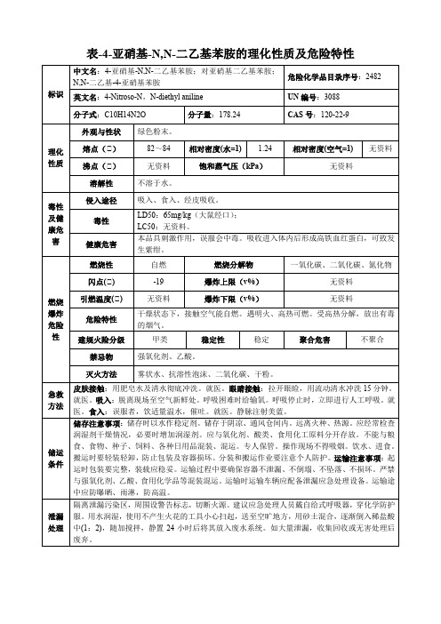
隔离泄漏污染区,周围设警告标志,切断火源。建议应急处理人员戴自给式呼吸器,穿化学防护服。用水润湿,使用不产生火花的工具小心扫起,送至空旷地方,用砂土混合,逐渐倒入稀盐酸中(1:2),随加搅拌,静置24小时后将其放入废水系统。如大量泄漏,收集回收或无害处理后废弃。
燃烧爆炸危险性
燃烧性
自燃
燃烧分解物
一氧化碳、二氧化碳、氮化物
闪点(℃)
-19
爆炸上限(v%)
无资料
引燃温度(℃)
无资料
爆炸下限(v%)
无资料
危险特性
干燥状态下,接触空气能自燃。遇明火、高热可燃。受高热分解,放出有毒的烟气。
建规火险分级
甲类
稳定性
稳定
聚合危害
不聚合
禁忌物
强氧化剂、乙酸。
灭火方法
雾状水、抗溶性泡沫、二氧化碳、干粉。
熔点(℃)
82~84
相对密度(水=1)
1.24
相对密(kPa)
无资料
溶解性
不溶于水。
毒性及健康危害
侵入途径
吸入、食入、经皮吸收。
毒性
LD50:65mg/kg(大鼠经口);
LC50:无资料。
健康危害
本品具刺激作用,误服会中毒。吸收进入体内后形成高铁血红蛋白,可致发生紫绀。
急救方法
皮肤接触:用肥皂水及清水彻底冲洗。就医。眼睛接触:拉开眼睑,用流动清水冲洗15分钟。就医。吸入:脱离现场至空气新鲜处。呼吸困难时给输氧。呼吸停止时,立即进行人工呼吸。就医。食入:误服者,饮适量温水,催吐。就医。静脉注射美蓝。
储运条件
储存注意事项:储存时以水作稳定剂。储存于阴凉、通风仓间内。远离火种、热源。应经常检查润湿剂干燥情况,必要时增加润湿剂。应与氧化剂、酸类、食用化工原料分开存放。不能与粮食、食物、种子、饲料、各种日用品混装、混运。专人保管。操作现场不得吸烟。饮水、进食。搬运时要轻装轻卸,防止包装及容器损坏。分装和搬运作业要注意个人防护。运输注意事项:起运时包装要完整,装载应稳妥。运输过程中要确保容器不泄漏、不倒塌、不坠落、不损坏。严禁与强氧化剂、乙酸、食用化学品等混装混运。运输时运输车辆应配备泄漏应急处理设备。运输途中应防曝晒、雨淋,防高温。
三(2,2,6,6-四甲基庚二酮酸)镧 Lanthanum 3 (2,2,6,6-Tetrameth

化学品安全技术说明书 SDS ALC-SDS- P046Ver.2三(2,2,6,6-四甲基庚二酮酸)镧Lanthanum 3 (2,2,6,6-Tetramethylheptanedionate)化学品中文名称:三(2,2,6,6-四甲基庚二酮酸)镧化学品英文名称:Lanthanum 3 (2,2,6,6-Tetramethylheptanedionate); Lathd 3化学分子式:(LaC33H57O2)3or La3C33H57O6企业名称(中英文):液化空气(中国)投资有限公司Air Liquide (China)Holding Co., Ltd.地址:上海市徐汇区古美路1515号18号楼Building18, No.1515 Gu Mei Road, Shanghai, China电话:************传真:************电子邮件地址:************************24小时化学事故应急咨询专线:*************产品推荐及限制用途:仅限用于科学研发,药物合成或出口(根据40 CFR 720.36和721.47定义)。
必须在具有技术资质人员的直接监督下使用该产品。
本产品用于其它用途时,必须提前向供应商咨询。
危害概述:无色易燃固体。
本品毒理学特性未完全建立。
可能刺激呼吸系统,眼睛及皮肤。
仅供研究使用。
尽可能减少接触可能。
其主要健康危害可能刺激皮肤、眼睛、皮肤和其他受污染组织。
易燃,在特定环境下,该产品小颗粒粉尘可自燃,遇明火燃烧产生烟雾,刺激性蒸汽及有毒气体(如一氧化碳,氧化镧等);遇水,空气均能产生反应;对水环境有害紧急处置人员需佩戴合适的个人防护设备。
GHS危险性类别:●物理化学危险易燃固体–类别1。
标签要素●象形图:●警示词:危险●危险性说明:易燃固体防范说明●预防戴防护手套/穿防护服/戴防护眼罩/戴防护面具;远离热源/火花/明火/热表面-禁止吸烟;容器和接收设备接地/等势连接;使用防爆的电气/通风照明设备;只能使用不产生火花的工具;采取防止静电放电的措施。
4硝基2甲氧基苯胺安全技术说明书MSDS
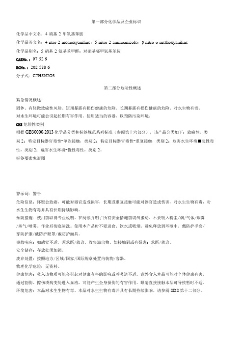
第一部分化学品及企业标识化学品中文名:4-硝基-2-甲氧基苯胺化学品英文名:4-ntro-2-methoxyaniline;5-nitro-2-aminoanisole;ρ-nitro-o-methoxyaniline化学品别名:5-硝基-2-氨基苯甲醛;对硝基邻甲氧基苯胺CASNo.:97-52-9ECNo.:202-588-6分子式:C7H8N2O3第二部分危险性概述紧急情况概述固体。
有轻微致癌性风险。
短期暴露有损伤健康的危险。
长期暴露有损伤健康的危险。
对水生物有毒。
对水生环境可能会引起长期有害作用。
使用适当的容器,以预防污染环境。
GHS危险性类别根据GB30000∙2013化学品分类和标签规范系列标准(参阅第十六部分),该产品分类如下:致癌性,类别2;特定目标器官毒性-单次接触,类别2;特定目标器官毒性-重复接触,类别2;危害水生环境■急性毒性,类别2;危害水生环境-慢性毒性,类别2。
标签要素象形图警示词:警告危险信息:怀疑会致癌,可能对器官造成损害,长期或重复接触可能对器官造成伤害,对水生生物有毒,对水生生物有毒并具有长期持续影响。
预防措施:使用前取得专业说明。
在阅读并明了所有安全措施前切勿搬动。
不要吸入粉尘/烟/气体/烟雾/蒸气/喷雾。
作业后彻底清洗。
使用本产品时不要进食、饮水或吸烟。
避免释放到环境中。
戴防护手套/穿防护服/戴防护眼罩/戴防护面具。
事故响应:如感觉不适,须求医/就诊。
收集溢出物。
如接触到或有疑虑:求医/就诊。
安全储存:存放处须加锁。
废弃处置:按照地方/区域/国家/国际规章处置内装物/容器。
物理化学危险:无资料。
健康危害:吸入该物质可能会引起对健康有害的影响或呼吸道不适。
意外食入本品可能对个体健康有害。
通过割伤、擦伤或病变处进入血液,可能产生全身损伤的有害作用。
眼睛直接接触本品可导致暂时不适。
环境危害:本品对水生生物有毒。
本品对水生生物有毒并具有长期持续影响。
请参阅SDS第十二部分。
常用危险化学品的分类及标志
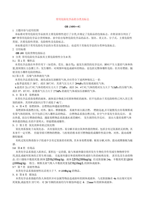
常用危险化学品的分类及标志GB 13690—921 主题内容与适用范围本标准对常用危险化学品按其主要危险特性进行了分类,并规定了危险品的包装标志。
在附录部分列出了997种常用危险化学品分类明细表。
表中给出每种危险化学品的品名、别名、英文名、分子式、主要危险性类别、次要危险性类别、危险特性及危险标志。
本标准适用于常用危险化学品的分类及包装标志,也适用于其他化学品的分类和包装标志。
2 引用标准GB 190 危险货物包装标志3 分类常用危险化学品按其主要危险特性分为8类:3.1 第1类爆炸品本类化学品指在外界作用下(如受热、受压、撞击等),能发生剧烈的化学反应,瞬时产生大量的气体和热量,使周围压力急骤上升,发生爆炸,对周围环境造成破坏的物品,也包括无整体爆炸危险,但具有燃烧、抛射及较小爆炸危险的物品。
3.2 第2类压缩气体和液化气体本类化学品系指压缩、液化或加压溶解的气体,并应符合下述两种情况之一者:a.临界温度低于50℃,或在50℃时,其蒸气压力大于294kPa的压缩或液化气体;b.温度在21.1℃时,气体的绝对压力大于275kPa,或在54。
4℃时,气体的绝对压力大于715kPa的压缩气体;或在37。
8℃时,雷德蒸气压力大于275kPa的液化气体或加压溶解的气体。
3。
3 第3类易燃液体本类化学品系指易燃的液体、液体混合物或含有固体物质的液体,但不包括由于其危险特性已列入其它类别的液体。
其闭杯试验闪点等于或低于61℃。
3。
4 第4类易燃固体、自燃物品和遇湿易燃物品易燃固体系指燃点低, 对热、撞击、摩擦敏感,易被外部火源点燃,燃烧迅速,并可能散发出有毒烟雾或有毒气体的固体, 但不包括已列入爆炸品的物品。
自燃物品系指自燃点低, 在空气中易发生氧化反应,放出热量, 而自行燃烧的物品. 遇湿易燃物品系指遇水或受潮时,发生剧烈化学反应,放出大量的易燃气体和热量的物品.有的不需明火,即能燃烧或爆炸。
3。
5 第5类氧化剂和有机过氧化物氧化剂系指处于高氧化态,具有强氧化性,易分解并放出氧和热量的物质。
