NX变频器共直流母线用户手册(英文版)
高压变频器使用手册——中英文版-第3章
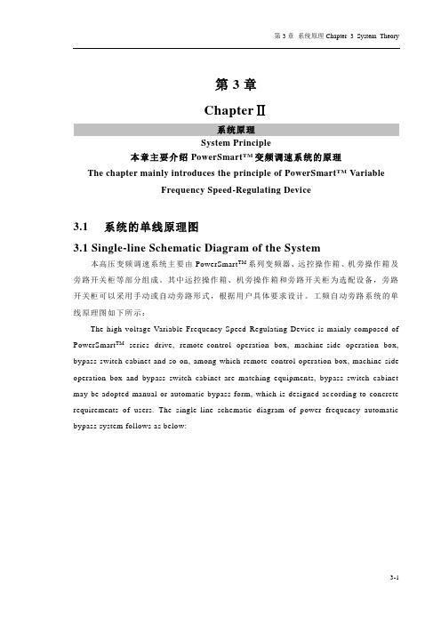
第3章ChapterⅡ系统原理System Principle本章主要介绍PowerSmart TM变频调速系统的原理The chapter mainly introduces the principle of PowerSmart TM VariableFrequency Speed-Regulating Device3.1系统的单线原理图3.1 Single-line Schematic Diagram of the System本高压变频调速系统主要由PowerSmart TM系列变频器、远控操作箱、机旁操作箱及旁路开关柜等部分组成。
其中远控操作箱、机旁操作箱和旁路开关柜为选配设备,旁路开关柜可以采用手动或自动旁路形式,根据用户具体要求设计。
工频自动旁路系统的单线原理图如下所示:The high-voltage Variable Frequency Speed-Regulating Device is mainly composed of PowerSmart TM series drive, remote-control operation box, machine-side operation box, bypass switch cabinet and so on, among which remote-control operation box, machine-side operation box and bypass switch cabinet are matching equipments, bypass switch cabinet may be adopted manual or automatic bypass form, which is designed ac cording to concrete requirements of users. The single-line schematic diagram of power frequency automatic bypass system follows as below:3-13-2图3-1 系统的单线原理图Fig3-1 Single-line Schematic Diagram of the System注:旁路开关柜中KM2、KM3采用高压真空接触器,QF1采用高压真空断路器。
VACON NXL变频器应用手册
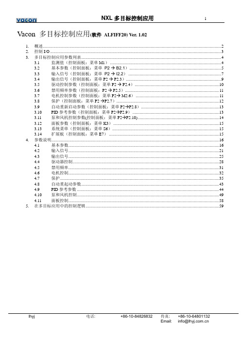
NXL多目标控制应用1 Vacon 多目标控制应用(软件ALFIFF20) Ver. 1.021. 概述 (2)2. 控制I/O (3)3. 多目标控制应用参数列表 (4)3.1 监测值(控制面板:菜单M1) (4)3.2 基本参数(控制面板:菜单P2 → B2.1) (5)3.3 输入信号(控制面板:菜单P2 → I2.2) (7)3.4 输出信号(控制面板:菜单P2 → P2.3) (9)3.5 驱动控制参数(控制面板:菜单P2 → P2.4) (10)3.6 禁用频率参数(控制面板:P2 → P2.5) (11)3.7 电机控制参数(控制面板:菜单P2→ M2.6) (11)3.8 保护(控制面板:菜单P2 →P2.7) (12)3.9 自动重新启动参数(控制面板:菜单P2→P2.8) (13)3.10 PID参考参数(控制面板:菜单P2→P2.9) (13)3.11 泵和风机控制参数(控制面板:菜单P2→P2.10) (14)3.12 面板参数(控制面板:菜单K3) (15)3.13 系统菜单(控制面板:菜单S6) (15)3.14 扩展板(控制面板:菜单E7) (15)4. 参数说明 (16)4.1 基本参数 (16)4.2 输入信号 (21)4.3 输出信号 (25)4.4 驱动器控制 (28)4.5 禁用频率 (31)4.6 电机控制 (32)4.7 保护 (35)4.8 自动重起动参数 (43)4.9 PID参考参数 (44)4.10 泵和风机控制 (49)4.11 面板控制 (58)5. 在多目标应用中的控制逻辑 (59)lhyj 电话: +86-10-84826832 传真: +86-10-64801132Email: *************.cn12NXL多目标控制应用多目标控制应用1. 概述缺省情况下,Vacon NXL变频器的多目标控制应用使用来自模拟输入1的直接频率参考。
NX-series EtherCAT Coupler Unit用户手册说明书
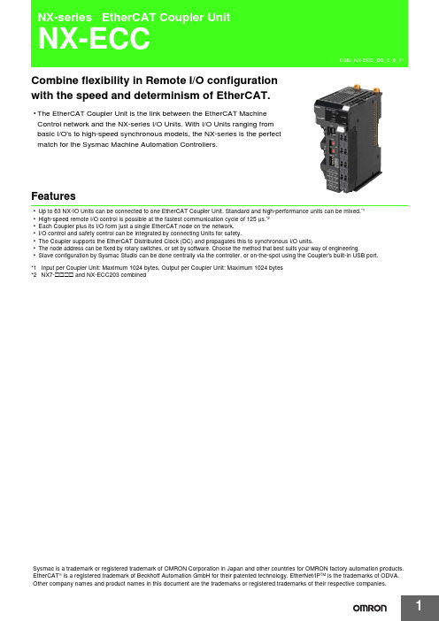
Combine flexibility in Remote I/O configurationwith the speed and determinism of EtherCAT.•The EtherCAT Coupler Unit is the link between the EtherCAT MachineControl network and the NX-series I/O Units. With I/O Units ranging frombasic I/O's to high-speed synchronous models, the NX-series is the perfectmatch for the Sysmac Machine Automation Controllers.Features•Up to 63 NX-IO Units can be connected to one EtherCAT Coupler Unit. Standard and high-performance units can be mixed.*1•High-speed remote I/O control is possible at the fastest communication cycle of 125 μs.*2•Each Coupler plus its I/O form just a single EtherCAT node on the network.•I/O control and safety control can be integrated by connecting Units for safety.•The Coupler supports the EtherCAT Distributed Clock (DC) and propagates this to synchronous I/O units.•The node address can be fixed by rotary switches, or set by software. Choose the method that best suits your way of engineering.•Slave configuration by Sysmac Studio can be done centrally via the controller, or on-the-spot using the Coupler's built-in USB port.*1Input per Coupler Unit: Maximum 1024 bytes, Output per Coupler Unit: Maximum 1024 bytes*2NX7-@@@@ and NX-ECC203 combinedSysmac is a trademark or registered trademark of OMRON Corporation in Japan and other countries for OMRON factory automation products. EtherCAT is a registered trademark of Beckhoff Automation GmbH for their patented technology. EtherNet/IP TM is the trademarks of ODVA. Other company names and product names in this document are the trademarks or registered trademarks of their respective companies.System ConfigurationSystem Configuration of Slave TerminalsThe following figure shows an example of the system configuration when an EtherCAT Coupler Unit is used as a Communications Coupler Unit.*1.The connection method for the Sysmac Studio depends on the model of the CPU Unit or Industrial PC.*2.An EtherCAT Slave Terminal cannot be connected to any of the OMRON CJ1W-NC @81/@82 Position Control Units even though they canoperate as EtherCAT masters.*3.For whether NX Units can be connected to the CPU Unit or Communications Coupler Unit to be used, refer to the user's manual for the CPUUnit or Communications Coupler Unit to be used.EtherCAT master *2Sysmac Studio Support SoftwareOrdering InformationApplicable standardsRefer to the OMRON website () or ask your OMRON representative for the most recent applicable standards for each model.*1.This depends on the specifications of the EtherCAT master. For example, the values are as follows when the EtherCAT Coupler Unit isconnected to the built-in EtherCAT port on an NJ5-series CPU Unit: 500 μs, 1,000 μs, 2,000 μs, and 4,000 μs. Refer to the NJ/NX-series CPU Unit Built-in EtherCAT Port User’s Manual (Cat. No. W505) for the specifications of the built-in EtherCAT ports on NJ/NX-series CPU Units.*2.This depends on the Unit configuration.Recommended EtherCAT Communications CableUse a straight STP (shielded twisted-pair) cable of category 5 or higher with double shielding (braiding and aluminum foil tape) for EtherCAT.Cable with Connectors*1.Standard type cables length 0.2, 0.3, 0.5, 1, 1.5, 2, 3, 5, 7.5, 10, 15 and 20 m are available.Rugged type cables length 0.3, 0.5, 1, 2, 3, 5, 10 and 15 m are available.For details, refer to Cat.No.G019.*2.The lineup features Low Smoke Zero Halogen cables for in-cabinet use and PUR cables for out-of-cabinet use. Although the LSZH cable issingle shielded, its communications and noise characteristics meet the standards.*3.Cables colors are available in blue, yellow, or Green.*4.For details, contact your OMRON representative.Product nameCommunications cycle inDC Mode *1 *2Current consumptionMaximum I/O power supply current Model EtherCAT Coupler Unit250 to 4,000 μs 1.45 W or lower4 ANX-ECC20110 ANX-ECC202125 to 10,000 μs 1.25 W or lower NX-ECC203ItemAppearanceRecommended manufacturerCable length [m] *1ModelCable with Connectors on Both Ends (RJ45/RJ45)Standard RJ45 plugs type *1Wire gauge and number of pairs: AWG26, 4-pair cable Cable sheath material: LSZH *2Cable color: Yellow *3OMRON0.3XS6W-6LSZH8SS30CM-Y 0.5XS6W-6LSZH8SS50CM-Y 1XS6W-6LSZH8SS100CM-Y 2XS6W-6LSZH8SS200CM-Y 3XS6W-6LSZH8SS300CM-Y 5XS6W-6LSZH8SS500CM-Y Cable with Connectors on Both Ends (RJ45/RJ45)Rugged RJ45 plugs type *1Wire gauge and number of pairs: AWG22, 2-pair cable Cable color: Light blueOMRON0.3XS5W-T421-AMD-K 0.5XS5W-T421-BMD-K 1XS5W-T421-CMD-K 2XS5W-T421-DMD-K 5XS5W-T421-GMD-K 10XS5W-T421-JMD-K Cable with Connectors on Both Ends (M12 Straight/M12 Straight)Shield Strengthening Connector cable *4M12/Smartclick ConnectorsWire Gauge and Number of Pairs: AWG22, 2-pair Cable Cable color: BlackOMRON0.5XS5W-T421-BM2-SS 1XS5W-T421-CM2-SS 2XS5W-T421-DM2-SS 3XS5W-T421-EM2-SS 5XS5W-T421-GM2-SS 10XS5W-T421-JM2-SS Cable with Connectors on Both Ends (M12 Straight/RJ45)Shield Strengthening Connector cable *4M12/Smartclick Connectors Rugged RJ45 plugs typeWire Gauge and Number of Pairs: AWG22, 2-pair Cable Cable color: BlackOMRON0.5XS5W-T421-BMC-SS 1XS5W-T421-CMC-SS 2XS5W-T421-DMC-SS 3XS5W-T421-EMC-SS 5XS5W-T421-GMC-SS 10XS5W-T421-JMC-SSCables / ConnectorsWire Gauge and Number of Pairs: AWG24, 4-pair Cable*We recommend you to use above cable and connector together.Wire Gauge and Number of Pairs: AWG22, 2-pair Cable*We recommend you to use above cable and connector together.Note:Connect both ends of cable shielded wires to the connector hoods.Optional ProductsAccessoriesEnd Cover (NX-END01)An End Cover is connected to the end of the EtherCAT Slave Terminal.One End Cover is provided together with the EtherCAT Coupler Unit.ItemAppearanceRecommended manufacturerModelCables-Hitachi Metals, STAR-C5E SAB 0.5 × 4P CP *-Kuramo Electric Co.KETH-SB *-SWCC Showa Cable Systems Co.FAE-5004 *RJ45 Connectors-Panduit CorporationMPS588-C *ItemAppearanceRecommended manufacturer ModelCables-Kuramo Electric Co.KETH-PSB-OMR *-JMACS Japan Co., Ltd.PNET/B *RJ45 Assembly ConnectorOMRONXS6G-T421-1 *Product nameSpecificationModelUnit/Terminal Block Coding PinsPins for 10 Units(30 terminal block pins and 30 Unit pins)NX-AUX02Product NameSpecificationModelNo. of terminals Ground terminal mark Terminal current capacity Terminal Block8Present10 ANX-TBC082General Specification*Refer to the OMRON website (/) or consult your OMRON representative for the most recent applicable standards for each model.SpecificationsEtherCAT Coupler Unit NX-ECC201/NX-ECC202/NX-ECC203*1.Refer to the NX-series Safety Control Units User’s Manual (Cat. No. Z930) for the number of Safety Control Units that can be connected.*2.This function was added or improved for a version upgrade. Refer to the NX-series EtherCAT Coupler Unit User’s Manual (Cat. No. W519) forinformation on version upgrades.*3.The range of node addresses that can be set depends on the model of the built-in EtherCAT port. For the node address ranges that can beset for a built-in EtherCAT port, refer to the user's manual for the built-in EtherCAT port on the connected CPU Unit or Industrial PC.*4.This depends on the specifications of the EtherCAT master. For example, the values are as follows when the EtherCAT Coupler Unit isconnected to the built-in EtherCAT port on an NJ5-series CPU Unit: 500 μs, 1,000 μs, 2,000 μs, and 4,000 μs. For the specifications of the built-in EtherCAT port, refer to the user's manual for the built-in EtherCAT port on the connected CPU Unit or the Industrial PC.*5.This depends on the Unit configuration.*6.There are restrictions in the communications cycles that you can set for some of the NX Units. If you use any of those NX Units, set acommunications cycle that will satisfy the specifications for the refresh cycles that can be executed by the NX Unit. Refer to the appendix of the NX-series Data Reference Manual (Cat. No. W525-E1-07 or later) to see if there are restrictions on any specific NX Units. For information on the communications cycles that you can set, refer to the user’s manuals for the NX Units.*7.Refer to the NX-series EtherCAT Coupler Unit User’s Manual (Cat. No. W519) for procedures for designing the Unit power supply system andI/O power supply system.*e a voltage that is appropriate for the I/O circuits of the NX Units and the connected external devices.ItemSpecificationEnclosureMounted in a panel Grounding methodGround to 100 Ω or less Operating environmentAmbient operating temperature 0 to 55°CAmbient operating humidity 10% to 95% (with no condensation or icing)AtmosphereMust be free from corrosive gases.Ambient storage temperature −25 to 70°C (with no condensation or icing)Altitude2,000 m max.Pollution degree Pollution degree 2 or less: Meets IEC 61010-2-201.Noise immunity Conforms to IEC61000-4-4. 2 kV (power supply line)Overvoltage category Category II: Meets IEC 61010-2-201.EMC immunity level Zone BVibration resistance Conforms to IEC 60068-2-6.5 to 8.4 Hz with 3.5-mm amplitude, 8.4 to 150 Hz, acceleration of 9.8 m/s 2, 100 min each in X, Y, and Z directions (10 sweeps of 10 min each = 100 min total)Shock resistanceConforms to IEC 60068-2-27. 147 m/s 2, 3 times each in X, Y, and Z directions Applicable standards *cULus: Listed (UL 508 or UL61010-2-201), ANSI/ISA 12.12.01,EU: EN 61131-2, C-Tick or RCM, KC Registration, NK, and LRItemSpecificationNX-ECC201NX-ECC202NX-ECC203Number of connectable NX Units 63 Units max.*1Send/receive PDO data sizes Input: 1,024 bytes max. (including input data, status, and unused areas)Output: 1,024 bytes max. (including output data and unused areas)Mailbox data size Input: 256 bytes Output: 256 bytesMailboxEmergency messages and SDO requestsRefreshing methods *2•Free-Run refreshing •Synchronous I/O refreshing •Time stamp refreshing•Free-Run refreshing•Synchronous I/O refreshing •Time stamp refreshing •Task period prioritized refreshingNode address setting rangeWhen the settable node address range for the built-in EtherCAT port is 1 to 512*3•Set on switches: 1 to 199•Set with the Sysmac Studio: 1 to 512When the settable node address range for the built-in EtherCAT port is 1 to 192*3•Set on switches: 1 to 192•Set with the Sysmac Studio: 1 to 192I/O jitter performanceInputs: 1 μs max.Outputs: 1 μs munications cycle in DC Mode250 to 4,000 μs *4 *5125 to 10,000 μs *3 *4 *6Unit power supply *7Power supply voltage24 VDC (20.4 to 28.8 VDC)NX Unit power supply capacity10 W max.Refer to Installation orientation and restrictions for details.NX Unit power supply efficiency 70%Isolation methodNo isolation between NX Unit power supply and Unit power supply terminals Current capacity of power supply terminals4 A max.I/O powersupply *7Power supply voltage5 to 24 VDC (4.5 to 28.8 VDC) *8Maximum I/O power supply current4 A 10 A Current capacity of power supply terminals4 A max.10 A max.NX Unit power consumption1.45 W max. 1.25 W max.Current consumption from I/O power supply 10 mA max. (for 24 VDC)Dielectric strength 510 VAC for 1 min, leakage current: 5 mA max. (between isolated circuits)Insulation resistance100 VDC, 20 M Ω min. (between isolated circuits)EtherCAT Communications Specifications*The EtherCAT Coupler Unit conforms to EtherCAT standards. Check the specifications of the EtherCAT master being connected for the configurable topology. However, note that only NX-ECC203 EtherCAT Coupler Units (Ver. 1.5 or later) is compatible with a ring topology.Version InformationNote:Some Units do not have all of the versions given in the above table. If a Unit does not have the specified version, support is provided by theoldest available version after the specified version. Refer to the user's manuals for the specific Units for the relation between models and versions.*1For the NX-ECC202, there is no unit version of 1.1 or earlier.*2For the NX-ECC203, there is no unit version of 1.2 or earlier.ItemSpecificationCommunications standard IEC 61158 Type 12Physical layer 100BASE-TX (IEEE 802.3)Modulation Baseband Baud rate 100 MbpsTopologyDepends on the specifications of the EtherCAT master. *Transmission mediaCategory 5 or higher twisted-pair cable (Recommended cable: double-shielded cable with aluminum tape and braiding)Transmission distance Distance between nodes: 100 m or lessModel number of EtherCAT Coupler UnitUnit version Corresponding versionsUsing an NX-series CPU Unit Using an NJ-series CPU Unit Using an NY-series Industrial PC Unit version of CPU UnitSysmac StudioversionUnit version of CPU Unit Sysmac Studioversion Unit version of Industrial PCSysmac StudioversionNX-ECC201Ver. 1.2Ver. 1.10Ver. 1.13Ver. 1.07Ver. 1.08Ver. 1.12Ver. 1.17Ver. 1.1Ver. 1.06Ver. 1.07Ver. 1.0Ver. 1.05Ver. 1.06NX-ECC202Ver. 1.2*1Ver. 1.07Ver. 1.08NX-ECC203Ver. 1.7Ver. 1.41Ver. 1.41Ver. 1.41Ver. 1.6Ver. 1.25Ver. 1.25Ver. 1.25Ver. 1.5Ver. 1.19Ver. 1.19Ver. 1.19Ver. 1.4Ver. 1.16Ver. 1.16Ver. 1.17Ver. 1.3*2Ver. 1.13Ver. 1.13External InterfaceEtherCAT Coupler Unit NX-ECC20@Terminal BlockApplicable Terminal Blocks for Each Unit ModelSymbol NameFunction(A)NX bus connectorThis connector is used to connect each Unit.(B)IndicatorsThe indicators show the current operating status of the Unit.(C)Communications connectors These connectors are connected to the communications cables of the EtherCAT network.There are two connectors, one for the input port and one for the output port.(D)Peripheral USB port This port is used to connect to the Sysmac Studio Support Software.(E)Terminal block The terminal block is used to connect external devices.The number of terminals depends on the type of Unit.(F)Rotary switches These rotary switches are used to set the 1s digit and 10s digit of the node address of the EtherCAT Coupler Unit as an EtherCAT slave. The address is set in decimal.(G)DIP switchThe DIP switch is used to set the 100s digit of the node address of the EtherCAT Coupler Unit as an EtherCAT slave.Symbol NameFunction(A)Terminal number indications The terminal numbers (A1 to A8 and B1 to B8) are displayed.The terminal number indicators are the same regardless of the number of terminals on the terminal block, as shown above.(B)Release holes Insert a flat-blade screwdriver into these holes to connect and remove the wires.(C)Terminal holes The wires are inserted into these holes.(D)Ground terminal markThis mark indicates the ground terminals. Only the NX-TBC082 has this mark.Unit modelCurrent capacity ofUnit's power supply terminals Terminal BlocksUnit power supplyI/O power supplyModelNo. of terminalsGround terminalmark Terminal currentcapacity NX-ECC201 4 A NX-TBC0828Present 10 A NX-ECC202 or NX-ECC2034 A10 ANX-TBC0828Present10 A(B)(D)(E)Eight-terminal Block(A)NX-TBC082Applicable WiresUsing FerrulesIf you use ferrules, attach the twisted wires to them.Observe the application instructions for your ferrules for the wire stripping length when attaching ferrules.Always use plated one-pin ferrules. Do not use unplated ferrules or two-pin ferrules.The applicable ferrules, wires, and crimping tool are given in the following table.*1.Some AWG 14 wires exceed 2.0 mm 2 and cannot be used in the screwless clamping terminal block.When you use any ferrules other than those in the above table, crimp them to the twisted wires so that the following processed dimensions are achieved.Using Twisted Wires/Solid WiresIf you use the twisted wires or the solid wires, use the following table to determine the correct wire specifications.*1Secure wires to the screwless clamping terminal block. Refer to the Securing Wires in the USER'S MANUAL for how to secure wires.*2With the NX-TB @@@1 Terminal Block, use twisted wires to connect the ground terminal. Do not use a solid wire.<Additional Information> If more than 2 A will flow on the wires, use plated wires or use ferrules.Terminal typesManufacturerFerrule model Applicable wire (mm 2 (AWG))Crimping toolTerminals other than ground terminalsPhoenix Contact AI0,34-80.34 (#22)Phoenix Contact (The figure in parentheses is the applicable wire size.)CRIMPFOX 6 (0.25 to 6 mm 2, AWG 24 to 10)AI0,5-80.5 (#20)AI0,5-10AI0,75-80.75 (#18)AI0,75-10AI1,0-8 1.0 (#18)AI1,0-10AI1,5-8 1.5 (#16)AI1,5-10Ground terminalsAI2,5-102.0 *1Terminals other than ground terminalsWeidmuller H0.14/120.14 (#26)Weidmueller (The figure in parentheses is the applicable wire size.)PZ6 Roto (0.14 to 6 mm 2, AWG 26 to 10)H0.25/120.25 (#24)H0.34/120.34 (#22)H0.5/140.5 (#20)H0.5/16H0.75/140.75 (#18)H0.75/16H1.0/14 1.0 (#18)H1.0/16H1.5/14 1.5 (#16)H1.5/16TerminalsWire typeWire sizeConductor length(stripping length)Twisted wires Solid wire Classification Current capacity Plated Unplated Plated UnplatedAll terminals except ground terminals2 A max.Possible Possible Possible Possible0.08 to 1.5 mm 2AWG28 to 168 to 10 mmGreater than2 A and 4 A or less Not Possible Possible*1NotPossible Greater than 4 A Possible *1NotPossibleGround terminals ---Possible PossiblePossible *2Possible*22.0 mm 29 to 10 mm1.6 mm max.2.0 mm max.(Ground terminals)(Ground terminals)Conductor length (stripping length)Dimensions(Unit: mm)EtherCAT Coupler Unit● EtherCAT Coupler Unit Only*The dimension is 1.35 mm for Units with lot numbers through December 2014.● With Cables Connected*1.*2.•• 1.5NX-ECC 11End Cover*This is the shape for Units with lot numbers through December 2014.Related Manuals Man. No Model Manual ApplicationDescription W519NX-ECC20@NX-series EtherCAT Coupler Unit User’s ManualLeaning how to use anNX-series EtherCATCoupler Unit andEther-CAT Slave Terminals The following items are described: the overall system and configuration methods of an EtherCAT Slave Terminal (which consists of an NX-series EtherCAT Coupler Unit and NX Units), and information on hardware, setup, and functions to setup, control, and monitor NX Units through EtherCAT.2020.6In the interest of product improvement, specifications are subject to change without notice. OMRON CorporationIndustrial Automation Company/(c)Copyright OMRON Corporation 2020 All Right Reserved.。
威肯变频器快速入门NX quickhelp
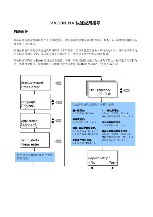
VACON NX 快速应用指导启动向导启动向导功能在变频器初次上电时被激活,或在系统菜单中设置相应参数(P6.5.3),并将变频器断电后再重新上电时激活。
控制面板的启动向导功能使变频器的调试非常简单。
当该功能置为有效(缺省设定)时,启动向导帮助用户选择语言和应用宏,或选择可用于所有应用宏,或专用于某个应用宏的参数值。
任何情况下均可按Enter 按钮接受参数值。
另外,可利用浏览按钮(向上或向下箭头)打开或关闭下拉菜单,或修改参数值。
控制面板的详细使用说明请参阅《NXS/P 变频器用户手册》第7章其他参数的设定取决于应用宏选择:基本应用宏:P2.14) 标准应用宏:P2.1.11) PID 控制应用宏:实际值1的选择(P2.2.9)PID 控制器参考值(P2.1.11多目标控制应用宏: I/O 参考值(P2.1.11)代码信号名称单位V1.1 输出频率Hz V1.2 频率参考值Hz V1.3 电机速度rpm V1.4 电机电流 A V1.5 电机转矩% V1.6 电机功率% V1.7 电机电压V V1.8 直流母线电压V V1.9 变频器温度ºC V1.10 电机温度% V1.11 电压输入V V1.12 电流输入mA V1.13 DIN1,DIN2,DIN3V1.14 DIN4,DIN5,DIN6V1.15 DO1,RO1,RO2V1.16 模拟输出mA M1.17 多监控项故障及故障代码监控值1 过电流2 过电压35 充电开关6 紧急停车7 饱和跳闸8 系统故障9101112 制动斩波器监控13 变频器温度过低14 变频器温度过高15161722 EEPROM求校验和故障24 计数器错误25 微处理器看门狗故障26 启动禁止2931 IGBT温度(硬件)32 风扇冷却34 CAN总线通讯35 应用宏36 控制单元37 设备变更(相同型号)38 设备增加(相同型号)39 设备移除40设备未知41 IGBT 温度4243 编码器故障44 设备变更(不同型号)45 设备增加(不同型号)504 2051 外部故障52 面板通讯故障53 现场总线故障54 插槽故障56 PT100板温度故障注意!不同的应用宏可能收录有更多的监控值实际值特殊显示“实际值特殊显示”参数可将实际值信号转化为更易于用户阅读的形式,并显示。
Vacon NX应用手册6
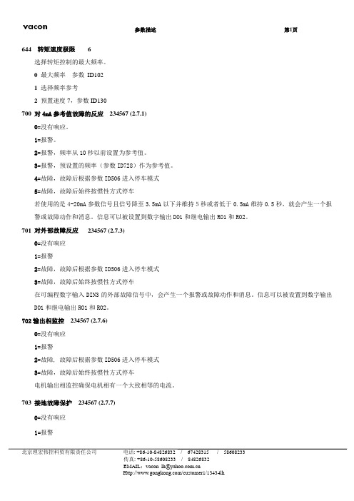
644 转矩速度极限 6选择转矩控制的最大频率。
0最大频率参数ID1021选择频率参考2预置速度7,参数ID130700 对4mA参考值故障的反应234567 (2.7.1)0=没有响应。
1=报警。
2=报警,频率从10秒以前设置为参考值。
3=报警,预设置的频率(参数ID728)作为参考值。
4=故障,故障后根据参数ID506进入停车模式5=故障,故障后始终按惯性方式停车若使用的是4-20mA参数信号且信号降至3.5mA以下并维持5秒或者低于0.5mA维持0.5秒,就会产生一个报警或故障动作和消息。
信息可以被设置到数字输出DO1和继电输出RO1和RO2。
701 对外部故障反应234567 (2.7.3)0=没有响应1=报警2=故障,故障后根据参数ID506进入停车模式3=故障,故障后始终按惯性方式停车在可编程数字输入DIN3的外部故障信号中,会产生一个报警或故障动作和消息。
信息可以被设置到数字输出DO1和继电输出RO1和RO2。
702输出相监控234567 (2.7.6)0=没有响应1=报警2=故障, 故障后根据参数ID506进入停车模式3=故障,故障后始终按惯性方式停车电机输出相监控确保电机相有一个大致相等的电流。
703 接地故障保护234567 (2.7.7)0=没有响应1=报警北京理宏伟控科贸有限责任公司电话: +86-10-84826832 / 67428315 / 586082332=故障,故障后根据参数ID506进入停车模式3=故障, 故障后始终按惯性方式停车接地故障保护确保电机相电流之和为零。
过电流保护始终在工作并保护变频器免受大电流接地故障的危害。
704 电机热保护234567 (2.7.8)0=没有响应1=报警2=故障,故障后根据参数ID506进入停车模式3=故障,故障后始终按惯性方式停车如果选择了跳闸,变频器会停机并且进入故障状态。
释放保护,例如设定参数为0,这会复位电机热状态到0%。
vaconnxl变频器应用手册
Vacon 多目标控制应用(软件 ALFIFF20) Ver.1. 概述................................................................... 错误!未定义书签。
2. 控制I/O ............................................................... 错误!未定义书签。
3. 多目标控制应用参数列表................................................. 错误!未定义书签。
监测值(控制面板:菜单M1).................................... 错误!未定义书签。
基本参数(控制面板:菜单 P2 ).............................. 错误!未定义书签。
输入信号(控制面板:菜单 P2 ).............................. 错误!未定义书签。
输出信号(控制面板:菜单P2 ).............................. 错误!未定义书签。
驱动控制参数(控制面板:菜单P2 ).......................... 错误!未定义书签。
禁用频率参数(控制面板:P2 )............................... 错误!未定义书签。
电机控制参数(控制面板:菜单P2)........................... 错误!未定义书签。
保护(控制面板:菜单P2 )................................... 错误!未定义书签。
自动重新启动参数(控制面板:菜单P2)........................ 错误!未定义书签。
PID参考参数(控制面板:菜单P2)............................. 错误!未定义书签。
艾默生NX

用户手册
资料版本V1.3
归档日期2013-09公司为客户提供全方位的技术支持,用户可与就近的艾默生网络能源有限公司办事处或客户服务中心联系,也可直接与公司总部联系。
艾默生网络能源有限公司
版权所有,保留一切权利。内容如有改动,恕不另行通知。
艾默生网络能源有限公司
地址:深圳市南山区科技工业园科发路一号
邮编:518057
公司网址:
客户服务热线:4008876510
E-mail: service@
安全注意事项
本手册内容涉及艾默生NXUPS的安装和使用。
警告:电池危险
电池的安装需要特别小心。连接电池时,电池端电压将超过400Vdc危险电压。
请配戴眼睛护罩,以免意外电弧伤害眼睛。
取下戒指,手表等所有其它金属佩戴物。
使用具有绝缘手柄的工具。
戴上橡胶手套。
如电池电解液泄漏或电池损坏,必须更换此电池,并将其置于抗硫酸的容器中,并根据当地规定进行报废处理。
如皮肤接触到电解液,应立即用水冲洗。
一.2
在安装UPS前,首先应进行如下检查:
1.目检UPS及电池内部和外部是否存在运输损坏。如有损坏,请立即通报承运商。
2.核对产品标签,确认设备的正确性。设备门后贴有设备标签,标签上标明了UPS型号、容量及主要参数。
一.3
一.3.1
UPS设计为室内安装,应安装在清洁的环境中,并且应通风良好,以保证环境温度满足产品规格要求(参见表8-2),例如:不能在高速路隧道,户外无空调等超出环境规格要求的情况下安装使用。
详细信息参见第八章产品规格。
设备的安装应遵照以上要求并使用厂家指定附件。
警告
VACONNXL变频器应用手册
V a c o n多目标控制应用(软件A L F I F F20)V e r.1.021. 概述...................................................................2.控制I/O ...............................................................3.多目标控制应用参数列表.................................................3.1监测值(控制面板:菜单M1)......................................3.2基本参数(控制面板:菜单P2 ✍ B2.1)............................3.3输入信号(控制面板:菜单P2 ✍ I2.2).............................3.4输出信号(控制面板:菜单P2 ✍ P2.3)............................3.5驱动控制参数(控制面板:菜单P2 ✍ P2.4)........................3.6禁用频率参数(控制面板:P2 ✍ P2.5).............................3.7电机控制参数(控制面板:菜单P2✍ M2.6).........................3.8保护(控制面板:菜单P2 ✍P2.7).................................3.9自动重新启动参数(控制面板:菜单P2✍P2.8)......................3.10PID参考参数(控制面板:菜单P2✍P2.9)...........................3.11泵和风机控制参数(控制面板:菜单P2✍P2.10).......................3.12面板参数(控制面板:菜单K3)....................................3.13系统菜单(控制面板:菜单S6)....................................3.14扩展板(控制面板:菜单E7)......................................4.参数说明...............................................................4.1基本参数 ........................................................4.2输入信号 ........................................................4.3输出信号 ........................................................4.4驱动器控制 ......................................................4.5禁用频率 ........................................................4.6电机控制 ........................................................4.7保护 ............................................................4.8自动重起动参数 ..................................................4.9PID参考参数.....................................................4.10泵和风机控制 ....................................................4.11面板控制 ........................................................5.在多目标应用中的控制逻辑...............................................多目标控制应用1. 概述不使用PID控制器时的直接频率参考,可以从模拟输入、总线、面板、预置速度或者电机电位器中选择。
VACONNXL变频器应用手册

V a c o n多目标控制应用(软件A L F I F F20)V e r.多目标控制应用1. 概述不使用PID控制器时的直接频率参考,可以从模拟输入、总线、面板、预置速度或者电机电位器中选择。
PID控制器参考可以从模拟输入、总线、PID面板参考1或通过数字输入的面板参考2。
PID控制器的实际值,可以从模拟输入,总线,电机的实际值中选择。
PID控制器也可以在变频器经过总线或者控制面板控制时使用。
•数字输入DIN2, DIN3, (DIN4) 和选件板输入DIE1, DIE2, DIE3 可以自由的编程。
•内部和选件板上的继电器以及模拟输出都可以自由编程。
•模拟输入1可以被用作电流输入、电压输入、DIN4数字输入进行编程。
注意!。
附加功能:•控制I/O,面板和总线都可以使用PID控制器•睡眠功能•实际值的监控功能:完全的可编程:关闭,报警,故障•可编程的启动/停止和反转的信号逻辑•参考标定• 2 个预置速度•模拟输入范围选择,信号标定,倒置,和滤波•频率极限监控•可编程的启动和停止功能•启动和停止时的直流制动•禁用频率区域•可编程的U/f 曲线和U/f 的优化•可调节的开关频率•故障之后的重新启动功能•保护和监控(完全的可编程:关闭,报警,故障):•电流输入故障•外部故障•输入和输出相•欠压•接地故障•电机过热,失速和欠载保护•热敏电阻•总线通讯•选件板PID控制器参考值2. 控制I/O表置(带3. 多目标控制应用参数列表下页是对应参数组的参数列表,每个参数包含了对参数描述的链接,在16页到44页中给定了各参数描述。
栏目说明:代码= 参数在面板上的定位; 告诉操作者当前的参数号码参数= 参数名称最小值= 参数的最小值最大值= 参数的最大值单位= 参数的单位值缺省值= 工厂的设置值用户= 用户自己设置ID = 参数的标识(ID)号,使用PC编程工具时应用= 当变频器停机时才能改变参数值监测值(控制面板:菜单M1)基本参数(控制面板:菜单P2 )输入信号(控制面板:菜单P2 )CP=控制位置 cc=常闭触点 oc=常开触点输出信号(控制面板:菜单P2 )驱动控制参数(控制面板:菜单P2 ✍)禁用频率参数(控制面板:P2 ✍)电机控制参数(控制面板:菜单P2✍)保护(控制面板:菜单P2 ✍)自动重新启动参数(控制面板:菜单P2✍)PID参考参数(控制面板:菜单P2✍)3.11 泵和风机控制参数(控制面板:菜单P2✍面板参数(控制面板:菜单K3)下面列出了面板上的用来选择控制位置和方向的参数。
科尼变频器中英文手册
HU4.07.0067 En Cn Owner’s Manual
Page 2 / (52)
用户手册
CONTENTS 目录
1 GENERAL 总则 ...................................................................................................................... 3
2. Verify all of the connections are in accordance to the drawings. 确认所有的连接跟图纸是一致.
3. Verify the motor supply is connected correctly, faulty connection will destroy the inverter. 确认马达的动力线连接正确.错误的连接会损坏变频器.
8. Do not touch the components on the circuit boards. Static voltage discharge may cause damage or destroy the IC-circuits. 不要用手接触电路板的元器件.系统的固有电压放电可能会损坏 IC 电路.
1.9.1 Fulfilled EMC-standards 现行的 EMC 标准 .................................................... 17
2 START-UP PROCEDURE 启动步骤 .................................................................................... 209
科尼变频器中英文手册

Vector IIVector IIOwner’s Manual用户手册CAUTION警告1. Before starting, read the instructions carefully. 在开始前.仔细阅读说明书.2. Verify all of the connections are in accordance to the drawings.确认所有的连接跟图纸是一致.3. Verify the motor supply is connected correctly, faulty connection willdestroy the inverter. 确认马达的动力线连接正确.错误的连接会损坏变频器.4. Check the device cover is properly installed.检查系统的罩盖已经正当安装.5. High voltages are present in this device. Switch the power off and afterthe display turns off, wait 5 minutes before opening the cover.系统内存在高电压.必须要等电源切断显示消失后5分钟才能打开罩盖.6. Insulation resistance test with a megger requires special precautions.兆欧表测量的绝缘电阻要符合标准值.7. Do not make any measurements inside the device when it is connectedto the main supply. 在系统中连接到主电源板的地方不要作任何测量8. Do not touch the components on the circuit boards. Static voltagedischarge may cause damage or destroy the IC-circuits.不要用手接触电路板的元器件.系统的固有电压放电可能会损坏IC电路.9. Check all ventilation holes are clear and uncovered.检查所有的通风口已经被清洁和没有被覆盖.10. Check that hot air coming from the brake resistors does not cause anydanger. 检查来自制动电阻的热空气不会引起任何危险.11. Do not make any inspections unless the supply has been disconnectedby the main switch. 除非在总开关切断电源的情况下否则不能作任何检查12. It is forbidden to use radiophones or portable phones near this devicewith the doors open. 禁止在门被打开的设备附近使用无线和移动通信装置.13. All the doors and covers must be closed during crane operation.在起重机使用其间必须保证所有的门和罩盖都是关闭的.This manual is valid for D2H and D2C revisions 5.3. The release number of this document isD2HCOM53BEN. The parameter numbers are based on the software version Pro1V030.CONTENTS目录总则 (3)1 GENERAL技术数据 (3)1.1 Technicaldata1.2 Type mark coding 类型标记 (4)1.3 Basic基本描述 (5)description主要部件 (7)1.4 Maincomponents功能描述 (8)1.5 Functionaldescription控制模式 (10)methods1.6 Control1.7 Mechanical brake control 机械制动控制 (14)1.8 Motor control modes 马达的控制论方式 (15)1.9 EMC (17)1.9.1 Fulfilled现行的EMC标准 (17)EMC-standards启动步骤 (209)2 START-UPPROCEDUREchecks目测 (209)2.1 Visual2.2 Checks before the first test run 检查以后的手次测试 (20)2.3 Test run without load 空载测试 (21)2.4 Test run with load 负载测试 (21)2.5 After the test run测试以后 (22)ADJUSTMENTS参数调整 (23)3 PARAMETER3.1 Control keypad operation 控制显示屏操作 (23)3.1.1 Navigation on the control keypad 控制显示屏演示 (25)3.1.2 Value line editing 数值的编辑 (25)密码 (26)3.1.3 Passwords3.1.4 Monitoring监控 (287)参数组 (298)3.2 Parametergroups部件 (309)4 COMPONENTS4.1 D2H spare parts list D2H的备品清单 (309)4.2 D2C spare parts list D2C的备品清单 (30)CODES故障代码 (31)5 FAULT5.1 Fault time data record 故障时间日期记录 (40)故障记数器 (40)Counter5.2 Fault服务 (42)6 SERVICE7 LAYOUTS, DIMENSIONS AND WEIGHTS系统布置尺寸和重量 (43)1 GENERAL 总则1.1 Technical data 技术数据Power class 功率等级002F 003F 004F 005F 007F 011F 015F 018F 022F 030F 037F 045F 055F 075F 090F 110F 132F Power (kVA) at 400V 功 率 4.5 5.5 7 9 13 17 22 29 33 40 50 60 75 100 120 150170Output current In(A)输出电流6.5 8 10 13 18 24 32 42 48 60 75 90 110 150 180 210245Max. current 1min (A)最大电10 12 15 20 27 36 48 63 72 90 113135165 225 270 315368Overloadability 过载能力1.5 x In , 1min/10min Max. output voltage 最大输出电压Equal to supply voltage Supply voltage 电源电压380-500VAC Allowable voltage fluctuation 电压波动 +/- 10%Nominal supply frequency 电源频率50/60Hz +/- 5% Signal input levels 信号输入标准Digital controls 数字控制S1, S2, DIA3, DIA4, DIA5, DID1, DID2, DID3, DID4, DID5: 42 … 240VAC; 15mA Analog references 模拟参考值 AIN1: -10 … +10V and AIN2: 0 … 10V; 200k Ω; accuracy 0.5% Encoder feedback 脉冲编码器返馈 EA+/- and EB+/-; 0/24V; 3k Ω; floating differential inputsControl features 控制特点Control method 控制模式Open loop or closed loop vector control Frequency control range 频率控制范围 0 ... 250HzFrequency command 频率命令Potentiometer, motor potentiometer, 2-4-step controller or 0 ... 10V analog signal Limit switch functions 限位开关功能Slowdown and stop limit inputs for both directions Speed control range 速度控制范围Open loop vector control s N ... 100% (s N = motor nominal slip) Closed loop vector control 0 ... 100%Speed accuracy 速度控制精度Open loop vector control 1% of nominal speed at speed range 10 ... 100% 1/3 of motor nominal slip at speed below 10%Closed loop vector control 0.01% of nominal speedExtended speed range 扩展速度范围100 ... 200% Braking torque 制动力距150% Protections 保护Stall prevention 失速预防During acceleration and constant speed Motor overload protection 马达过栽保护 Thermistor based temperature measurementOverload protection 过栽保护Fault is detected if the current momentarily exceeds 280% of rated current Undervoltage / blown fuse 低压/烧保险 Fault is detected if DC voltage drops below 333VOvervoltage protection 过压保护Fault is detected if DC voltage exceeds 911V Momentary power loss 片刻电源丢失Immediate fault stop Inverter overtemperature 变频器过热Temperature sensor on the heat sink Mechanical brake 机械制动Circuit breaker Braking transistor 可控电制动Electronic supervision for the braking chopper and for the braking resistor Ground fault 接地故障Provided by electronic circuitry Overspeed/stall,超速/失速/速度差异检查 speed difference supervision Independent measurement using pulse wheel or encoderAmbient conditions 外界条件Ambient temperature 外界温度 -10°C ... +55°C (14°F ... 131°F) for ED ≤60% Storage temperature 储藏温度 -40°C ... +60°C (-31°F ... 140°F) dryHumidity 湿度<95%RH (no condensation) Altitude 海拔Maximum 1000m at In. Above 1000m: In reduces 1% per each 100m. Above 3000m: consult factory.Vibration 振动Operation: maximum displacement amplitude 3mm at 2-9Hz. Maximum acceleration amplitude 0.5g (5m/s²) at 9-200HzConforms to LV and EMC directives.1.2 Type mark coding 变频器型号标识D2H and D2C can be summarized as "crane motor control systems, which controls the speed by changing the frequency of supply voltage of a squirrel cage motor". A stepless speed adjustment can be achieved by this method. D2H 和D2C 可以概括为一种通过改变鼠笼马达电压的频率来控制马达速度的起重机控制方式.通过这种方式可以实现一个无级调速机构.Type marking is shown below. 型号标识如下:Control voltage 控制电Y 42VAC, 50/60Hz V Device name 系统名字 D2HD2CPower rating class 功率等级002 – 132D2H 007 F Supply voltage 供电电压 F 380 - 500VAC, 50/60Hz 压 P 48VAC, 50/60HzT 115VAC, 50/60Hz V 230VAC, 50/60Hz 53 Revision code 版本代码The latest revision may differ 最新的版本可能有差异D2H 007 F V 53 A 0 0 1 0Braking type 制动类型 A External resistor 外接电阻 B Internal resistor (included only D2C up to 015F) 内接电阻 AMounting 安装0 Standard panel 标准格式 0Emission level 散热等级 0 Unlimited (non EU-area or non-grounded network) 无限制 N Limited (EU-area, grounded network) 有限制 0Boards 速度检测板0 Standard 标准配置 1 Standard with speed supervision 带有速度检测的标准配置 2 Profibus 总线控制 3 Profibus with speed supervision 带有速度检测的总线控制 8 Relay 继电器控制 9 Relay with speed supervision 带有速度检测的继电器控制 1Special 特别选择 0 None 无L Varnished boards 油漆色卡 01.3 Basic description简要描述D2H and D2C have many advantages and offer many new features, when compared to other inverter based systems, which might be used in crane applications. D2H和D2C在起重机运用方面同其他通用变频器相比有许多优点和特点.Inverter 变频器The inverter in D2H and D2C is a crane inverter. The specific crane features for the inverter hardware and the special software are achieved by combining the experience and know-how of crane applications with the latest technology. The inverter uses vector calculation for several different motor control modes. 变频器在D2H, D2C中是起重机专用变频器.通过结合经验和在起重机运用技能方面的先进技术来获得特殊起重机变频器硬件和软件的特色.Crane user interface 起重机和D2H,D2C的变口All D2H and D2C have exactly the same interface with pre-designed locations for all typical crane functions. The main part of this interface is carried out by a terminal strip, which has separated sections for signals with main, control and electronics voltage levels. 针对所以具有代表性的起重机的功能,D2H D2C都有设计预留的相同的接口.主要接口部件是通过端子执行命令而且主电源和控制电源以及电源线是分开.Brake control 制动控制D2H and D2C include the brake contactor for disk brakes. D2H also includes it’s own DC-rectifier. D2H和D2C包括了控制盘式制动器的刹车接触器.还包括了制动器直流镇流器.Electrical braking 电气制动D2H and D2C include a braking transistor, which is dimensioned for every crane application. For resistor braking D2H and D2C are equipped with external resistor, D2C also with internal braking resistor up to 015F.每一台起重机的应用D2H D2C包括了制动可控硅.D2H D2C配置有外置刹车电阻.一直到015F为止的D2C配置的是内置刹车电阻.Control methods 控制模式D2H and D2C can be controlled by the electronic potentiometer control with 2-step pushbuttons, the potentiometer control with analog joystick-type control, the automation control with PLC and radio controls and by the multistep control with 2-4-step controllers. All these control methods are available with every D2H and D2C. 二档按钮电位计控制,摇杆电位计控制,PLC自动控制和二-四档的无级遥控控制都能操作D2H和D2C系统.所有的控制方式适用每一个D2H和D2C.Limit switch functions 限位开关功能D2H and D2C have built-in slowdown and stop limit switch functions for both running directions. D2H和D2C多有内在的双向减速和停止功能.Speed supervision 速度检测D2H includes a speed supervision unit SSU, which is separate from the inverter and not dependent on software. This safety circuitry is used to monitor the speed of the motor. In case of speed difference, overspeed or stall, the speed supervision unit stops the motion immediately. D2C can also be equipped with SSU. D2H包括了一个速度检测单元SSU.它跟变频器是分开的.也不依赖系统软件.它的安全电路监视马达的速度.引起的速度差异, 超速或失速, 速度检测单元能马上停止机构. SSU也能适用D2C.Protections 保护D2H and D2C include a motor thermal protection, which is based on motor temperature measurement by thermistors placed in the motor windings. A great number of other protections included in every D2H and D2C are shown in the technical data. D2H和D2C包括一个马达的热保护. 它由安置在马达绕组内的热敏电阻组成马达的测量系统.在技术参数中显示D2H和D2C还包括许多其他保护.1.4 Main components 主要部件The main components are: 主要部件是:D2H D2CA1 Inverter变频器002-132F 002-132FF7 Brake supply circuit breaker刹车供电断路器007-132F 002-045FK7 Brake contactor刹车接触器002-132F 002-045FG1 Brake control unit REC12刹车控制单元REC12 002-011FG1 Brake control unit ESD141 刹车控制单元ESC142 015-132F055-132F 055-132FF71 Circuit breaker for the second brake contactor二级刹车供电断路器二级刹车接触器K71 Second brake contactor二级刹车接触器055-132F 055-132F002-015F R1 Internal braking resistor unit (only D2C B-models)内置刹车电阻 (仅仅是D2CB模式)The most important external components are: 大部分重要的外围部件是:R1 External braking resistor unit for A-models外置刹车电阻 (仅仅是D2CA模式)M1 Motor马达Y1 Mechanical brake机械刹车A5 KAE234 Proximity switch buffer amplifier for speed sensor 速度传感器 (接近开关) 的缓冲放大器KAE234B5 Speed sensor (P-models)速度传感器 (仅仅是P模式)B6 Encoder (N-models) 脉冲编码器 (仅仅是N模式)Thermal sensor for motor protection 马达保护的温度传感器Overload protection device (e.g. Premium) 超载保护设备 (例如: Premium)Control devices (switches, pushbuttons, potentiometers etc.) 控制设备 (限位按钮电位计等等)Limit switches 限位开关1.5 Functional description功能描述See circuit diagrams for following descriptions of operation.对于以下操作的描述.请参见电路图纸.Operation when power is switched on.电源启动后的操作− Limit switches S11, S12, S21 and S22 are assumed to be closed, as well as the emergency stop button ES.假定限位开关S11, S12, S21, S22 还有紧急停止按钮都是闭合.− The control voltage is supplied to A1 control inputs (external 42V…230V control voltage). The main voltage is connected to inverter power supply and inverter wakes up. If the control voltage is connected to RDY-signal and the fault circuit is OK, inverter is ready to operate in about 1-2 seconds. A1控制单元接收控制电压的输入(外部电压42V-230V) 变频器的主电源也连接好, 此时变频器被激活, 如果控制电压也已连接到RDY信号以及故障电路是正常, 那么在1~2秒时间变频器已缴作好操作.− If either one of the direction signals S1 or S2 is on, the display shows F6 and running can begin only after the direction signals have been off for a while. 如果方向信号S1或S2接通,那么显示器显示F6,同时方向信号消失一会儿后运行才能开始.Normal operation正常操作– For the description of the speed reference setting see chapter 1.6 "Control methods". 关于速度参考设定的说明,可见1.6章”控制模式”.– Running starts when switch S1 (S2) closes. Closing the contact ROB2 on A1 energizes K7, which opens the brake (in models 055F-132F the brake can be controlled also by K71). D2H and D2C accelerate according to the acceleration ramp setting to the selected speed.当开关S1(S2)闭合时机构开始动作.变频器A1的ROB2继电器闭合使K7得电, 打开制动器.(在型号为055F-132F的产品中,制动器也可以通过K71来控制).D2H和D2C是按照设定的加速度来执行加速的.– When the switch S1 (S2) opens, D2H and D2C stop according to the deceleration ramp setting and the brake closes.当开关S1(S2)断开时, D2H和D2C是按照设定的加速度来执行停止.并使抱闸抱拢.– R1 dissipate the regenerated energy during deceleration and lowering periods. The power supply to R1 is controlled by A1. If the braking resistor fan(s) are included in external resistor unit, they start to operate when power is supplied to the braking resistors. The cooling continues about 4-5 minutes after electrical braking to ensure that the temperature of the resistors drops below 150°C (302°F).系统在减速和下降期间产生的在生能量在R1消耗. R1的电源有A1控制.如果制动电阻单元包括冷却风扇, 那么R1得电同时风扇也工作.连续4-5分钟冷却可以确保制动电阻的温度下级到150°C (302°F) 以下.Other features 其他特性– Slowdown limit switches S11 and S21 provide position dependent frequency limiting. S11 S12限位通过低频来获得减速的区域.– Any reason, which opens the contact RDY, stops the operation of inverter A1.不管任何理由RDY继电器打开,必然使运行的变频器停止.– In case of overload, motor overheating etc. the hoisting can be disabled by cutting the direction signal in terminal X1: 8.超载,马达过热等信号能切断方向信号的X1:8端子来阻止上升.– Thermistor relay function, which can be used when needed.当需要时,可以使用热敏电阻继电器的功能.– When the stop limit switch S12 or S22 opens, K7 (K71 in models 055F-132F) de-energizes and the mechanical brake stops the motion.当停止限位S12或S22打开,K7(在型号055F-132F中应为K71)失电,刹车停止工作.– Independent speed supervision unit, SSU.独立速度检测单元SSU.– The speed measurement and supervision can be done either with encoder, bearing encoder or proximity switch. The measured signals are square wave pulses. The frequency of the pulses is proportional to the speed of the motor and if the frequency is too high, overspeed is detected. If there are no pulses a stall situation is detected. If the actual speed differs too much from the supply frequency of the motor, the speed difference supervision stops the motion.轴承式脉冲编码器和接近开关二者之一都能成为速度的测量和检测单元.测量出的信号是方型波. 方型波的频率和马达的速度是成正比例. 如果方型波的频率太高,那么超速故障就被检查出. 如果方型波的频率为零, 那么失速故障就被检查出.如果供给马达的频率跟实际的速度有很大差别, 那么速度差异故障就被检查出并且停止机构.– Proximity switch buffer amplifier amplifies the sensor pulses and filters out disturbances. The amplifier is located close to the sensor.接近开关用缓冲放大器起放大和过滤作用,它被安置在传感器附近.– The extended speed range ESR can be used, if the signal FWE (field weakening enabled) is on. Then it is possible to run up to twice the nominal speed depending on the application.如果FEW(弱磁调速)信号接通,就能使用ESR速度扩展,它有可能使传动速度提高到正常速度的二倍,但取诀于实际运用.1.6 Controlmethods控制模式There are four different control methods (command modes) available. All of them are available without any changes in the hardware or software. Any single D2H or D2C can be controlled either by a pushbutton controller in EP-mode, by a joystick type controller with a potentiometer located in the cabin in PO-mode or by a process computer in AU-mode. The only external device needed is a switch to select the desired control method.有四种不同的控制模式(命令方式)可供使用. 使用中无需对硬件和软件作任何更改.由一个按钮控制器以EP方式,或者由带电位计的摇杆控制器固定在驾驶室以PO方式,或者由过程计算机以AU方式来控制单个D2H或者D2C.唯一需要的外部设备是一个开关来选择所期望的控制模式.EP Electronic motor potentiometer function.电动马达电位计功能− Stepless control using a 2-step pushbutton controller.利用二档按钮控制器实现无级控制.− EP3 stepless control using a 3-step controller.利用三档控制器实现EP3无级控制.PO Potentiometer control using a joystick type controller.使用遥杆控制器的电位计控制.− Requires a single 15V power supply (included in D2H/D2C).需要一个15V的单相电源(包括在D2H和D2C中)− Any additional amplifier is not needed.不需要任何附加的放大器AU Automation control自动控制− For any control device with an output in the range of 0-10V.− E.g. radio-controls, process computers.对任何具有0-10V电压输出的控制设备.例如:无线电控制器,过程计算机.MS Multistep control (2-4 steps as standard).多级控制 (标准2-4级)− Requires programmable digital inputs for speed reference steps(included in D2H/D2C).速度参考等级是由可编程的数字输入来定的.Command mode selection命令模式选择The command mode (EP, PO or AU) is selected by the switches CMS and AP. Normally the selection can be done only when the motion is stopped (not when running), but in special applications changing the mode is allowed during run by changing parameter values.命令方式(EP,PO,AU)可用开关CMS和AP来选择.通常只能在马停转时(不在运行时) 方可进行选择, 但某些特殊的运用场合, 通过改变参数值, 使得在马达运行其间也允许改变其命令方式.PO- and AU-modes PO和AU模式PO- and AU-modes select either of the analog inputs for speed reference. Both analog inputs can be adjusted similar from 0V to 10V (radio or PLC-reference) or from 10V to 6.7V (potentiometer). As default, Ain1 is used in PO-mode and Ain2 is used in AU-mode.PO和AU模式多选择了模拟输入作为速度参考.0-10V (遥控和PLC的参考值) 和10-6.7V(电位计的参考值)的电压值是可以调整的.缺省值:Ain1作为PO模式的模拟输入,Ain2作为AU模式的模拟输入.Ain1 / PO Ain1 / PO Ain2 / AU Ain2 / AU Ain1 / PODIA3 AP not usedAP没用AP not usedAP没用AP not usedAP没用AP = 0AP断开AP = 1AP闭合DIA4 CMS not usedCMS没用CMS = 0CMS断开CMS = 1CMS闭合CMS = 1CMS闭合CMS = 1CMS闭合EP-mode EP模式EP-mode selects the AP-button for speed reference. EP step 1 iscommand for minimum speed or hold speed. EP step 2 is the acceleration command.EP模式选择AP按钮用于速度参考, EP一档是低速或保持速度, EP二档是加速命令.EP step 1 EP step 2 EP step 1 EP step 2DIA3AP = 0AP断开AP = 1AP闭合AP = 0AP断开AP = 1AP闭合PDIA4CMS not usedCMS没用CMS not usedCMS没用CMS = 0CMS断开CMS = 0CMS断开Synchronization 同步传动If required, two or more D2H or D2C can be run in precise synchronization. A separate synchronization controller is needed for this. The same speed reference (in EP- or PO-mode) is connected to every D2H or D2C and the correction signal for synchronization is connected to all D2H or D2C to input AIN2+. The speed reference signal of each D2H or D2C can also be modified separately by a PLC. Synchronization is activated by parameter selection.如果需要,也可以对二个或多个D2H或D2C进行精确同步的传动.为此需要加装单独的同步控制器. 要将相同的速度参考值连接每个D2H和D2C,同步器的修正值连接所有的D2H和D2C的AIN2输入,每个D2H和D2C的速度参考值也可以由PLC进行单独修改.同步操作是由参数选择来执行的.Description of the control methods 控制模式的描述EP-control requires two 2-step pushbuttons, one for each direction. The operation is as follows: EP 控制要求二个双速按钮, 一个方向一个, 操作如下: − The rest position means standstill (0-position) 中位意思是停止位(0位)− During run the rest position means deceleration回到中位的运行意思是减速. − Step one (switch S1 or S2) means hold speed (S1或S2) 一档意思是保持速度.− When starting, step one means acceleration up to the minimum speed 刚开始时一档意思是加速到最小速度值. − Step two (switch AP) means acceleration (up tothe maximum speed if desired)二档(开关AP)意思是加速(加速到要求的最大速度值)− At the maximum speed step two means holdspeed, because the maximum speed cannot beexceeded在二档的最大速度值是保持速度,因为最大速度是不能确定的.shbutton position 按钮位置rest = deceleration 减速step 1 = hold speed 保持速度 EP-mode EP 模式 EP3-controloperation is as follows: EP3控制要求一个三档的控制器, 操作如下:− The rest position means standstill (0-position)中位意思是停止位(0位) − Step one (switch S1 or S2) is the minimum speed command 一档 (S1或S2方向)是最小速度命令.− Step two (EP hold command) means hold speed 二档(EP 保持档) 意思是保持速度.− Step three (switch AP) means acceleration (up tothe maximum speed if desired)三档(开关AP)意思是加速(加速到要求的最大速度值)− When releasing the controller, step one meansdeceleration down to the minimum speed当释放控制器到一档意思是减速到最小速度值.Pushbutton position 按钮位置rest = stop 停止EP3-mode EP3模式PO-control requires a controller with potentiometer. The operation is as follows:PC 控制要求一个带电位计的控制器, 操作如下: − When the controller is at the rest position the potentiometer is at the middle position causing zero speed 当控制器在停止位时, 电位计也在中间位, 结果是零速. − closing the direction switches (S1 and S2) 控制命令是由方向开关 (S1或S2)单独的闭合来控制的.− When the operator turns the controller to any direction, the speed increases 当操作者在任一方向转动控制器时 , 速度增加.− The same turning angle of the controller causes asmaller change in speed, the closer the speed isto the minimum speed 控制器相同的旋转角度会产PO- and AU-modes PO 和AU 模式生一个相同的速度变化, 控制器越接近关闭就越接近于最小速度.AU-control requires an analog reference from radioor PLC. The operation is as follows:AU控制要求一个来自遥控或者PLC的模拟参考值. 操作如下:− The speed linearly follows the input signal. 0Vmeans zero speed and the higher the voltage, thehigher the speed输入信号与速度成线性关系.0V意思是零速度.− Run commands are controlled separately byclosing the direction switches (S1 and S2)− 控制命令是由方向开关(S1或S2)单独的闭合来控制的.MS-controloperation is as follows: MS控制要求一个2-4档的控制器. 操作如下:− Each step has its own frequency每步多有自己固定的频率.− The frequencies are freely selectable频率能自由选择.− When controller is set to a certain step, the speedMS-mode MS模式changes to equal value 当控制手柄置于一个确定的档位, 那么速度的变化等于该档所对应的值.1.7 Mechanical brake control机械制动器控制The brake is controlled so that during starting the motor first generates torque and after that the brake is opened. The same applies for stopping; while the brake is being closed, the motor still generates torque. During a direction change, the brake is kept open all the time. D2H/D2C decelerate the motor to a stop according to the set deceleration time when the run command is switched off, so the brake is used only as a holding brake. This way brake wear is minimized. Only if a failure occurs or the emergency stop button is pushed, the brake closes immediately stopping the motor and the load. 制动器受电气控制,这样在启动期间,马达首先产生转矩,之后制动器才被打开.这同样也适合于停止. 当制动器闭合时,马达仍在产生转矩.在运行方向改变期间, 制动器始终保持打开. D2H/D2C在运行指令关掉后根据设定的减速时间对马达进行减速,直至停止.所以制动器仅仅是一种停止时抱闸刹车,这样制动器的磨损就可以减少到最小程度.只有在出现故障或按下紧急停车按钮时,制动器才会立即闭合,使马达和负载停止.The motors of CXT-hoists and SM-trolleys have an electromechanical disk brake. The disk brake is opened and kept open during run by DC-voltage. When there is no voltage present the brake is closed and also kept closed by spring force.CXT马达和SM小车马达都有一个电磁盘形制动器.在运行期间盘形制动器由直流电压加以打开并保持打开, 当直流电压不存在时, 制动器就闭合, 并依靠弹簧力来维持闭合状态.2-phase AC- D2C 002-045F D2C models 002F-045F include an AC-supply from two phases for the disk brake control. D2C controls this line and it is protected by an adjustable circuit breaker (max.4.0A). A rectifier included in the motor rectifies the AC-voltage to DC-voltage brake coils. D2C型号002F-045F 都装有两相交流电源用于盘形制动器的控制.D2C控制这一制动回路有一个可调的断路器(最大电流 4.0A)来作为保护. 马达中有一个整流模块,它将AC电压整流成DC电压来控制制动器线圈.REC12- D2H 002-011F D2H models 002F-011F have a built-in REC12 brake control unit, which is a line voltage half-wave rectifier (max.1.25Adc). The half-wave type rectifier reduces losses and is enough to open the brake. There is a contactor to switch the line voltage on and off. An external control unit is needed to control other brake types. D2H型号002F-011F有一个固化的REC12制动器控制单元,它是一个单相半波整流模块(最大.1.25Adc), 此种类型单相半波整流模块可以减少损耗而且足够打开制动器.有一个接触器来控制这一制动回路的开和关.如果需要控制其他类型的制动器那么需要一个外置的控制单元.ESD141- D2H 015-110F D2H models 015F-132F have a built-in ESD141 brake control unit, which is a line voltage full/half-wave rectifier (max.1.25Adc). Full-wave rectification is used to open the brake quickly. Then, the rectifier changes to a half-wave type, which reduces losses, but is enough to keep the brake open. There is a contactor to switch the line voltage on and off. The same contactor also disconnects the DC-voltage directly from the brake coil, which guarantees that the brake closes fast. An external control unit is needed to control other brake types. D2H型号015F-132F有一个固化的ESD141制动器控制单元,它是一个单相全波/半波整流模块(最大.1.25Adc),全波整流用来快速打开制动器,然后整流改变成半波,这样可以减少损耗而且足够打开制动器. 有一个接触器来控制单相电流的开和关.同一个接触器也能断开制动器线圈的直流电源,保证制动器快速关闭. 如果需要控制其他类型的制动器那么需要一个外置的控制单元.3-phase AC- D2H 055-110F - D2C 055-110F D2H and D2C models 055F-132F include a 3-phase AC-supply for the brake control. D2H and D2C control this line and it is protected by an adjustable circuit breaker (max.4.0A). When a shoe brake is used, brake closing is speeded up by capacitors. They are connected in parallel with the brake via the brake contactor NC-contacts. The connection is partially ready in D2H and D2C. Only the capacitors must be added outside D2H and D2C. This connection can also be used to control 2-phase disk brakes or a separate KA372B brake control unit.D2H和D2C型号的055F-132F产品有三相交流电源用于制动器的控制. D2H/D2C控制这一制动回路有一个可调的断路器(最大电流 4.0A)来作为保护.当使用闸瓦制动器时,由电容器使制动器快速闭合,电容器与制动接触器的常闭触点相并联.这种连接在D2H/D2C中部分已经准备好,只是电容必须加在D2H/D2C的外侧,这种连接方式也可以用来控制两相盘式制动器或一个独立的KA372B制动控制单元.1.8 Motor control modes 马达控制方式Open loop开环控制D2H and D2C have a built-in motor model, which calculates - one thousand times in a second - the values of the real motor. The input data needed for the calculation is the instantaneous value of the motor voltage from the ASIC and the measured motor current. Motor magnetic flux and shaft torque are calculated in the motor model based on the nameplate data of the motor. D2H/D2C内创建了一个一秒钟能计算一千次用于计算马达数值的马达模型,计算所须的输入数据为来自ASIC马达电压恒定值及测量到的马达电流,马达的励磁磁通和轴力矩也可在此基于马达铭牌数据的马达模型中得到计算。
VACON NXL变频器应用手册

NXL多目标控制应用1 Vacon 多目标控制应用(软件ALFIFF20) Ver. 1.021. 概述 (2)2. 控制I/O (3)3. 多目标控制应用参数列表 (4)3.1 监测值(控制面板:菜单M1) (4)3.2 基本参数(控制面板:菜单P2 → B2.1) (5)3.3 输入信号(控制面板:菜单P2 → I2.2) (7)3.4 输出信号(控制面板:菜单P2 → P2.3) (9)3.5 驱动控制参数(控制面板:菜单P2 → P2.4) (10)3.6 禁用频率参数(控制面板:P2 → P2.5) (11)3.7 电机控制参数(控制面板:菜单P2→ M2.6) (11)3.8 保护(控制面板:菜单P2 →P2.7) (12)3.9 自动重新启动参数(控制面板:菜单P2→P2.8) (13)3.10 PID参考参数(控制面板:菜单P2→P2.9) (13)3.11 泵和风机控制参数(控制面板:菜单P2→P2.10) (14)3.12 面板参数(控制面板:菜单K3) (15)3.13 系统菜单(控制面板:菜单S6) (15)3.14 扩展板(控制面板:菜单E7) (15)4. 参数说明 (16)4.1 基本参数 (16)4.2 输入信号 (21)4.3 输出信号 (25)4.4 驱动器控制 (28)4.5 禁用频率 (31)4.6 电机控制 (32)4.7 保护 (35)4.8 自动重起动参数 (43)4.9 PID参考参数 (44)4.10 泵和风机控制 (49)4.11 面板控制 (58)5. 在多目标应用中的控制逻辑 (59)lhyj 电话: +86-10-84826832 传真: +86-10-64801132Email: *************.cn12NXL多目标控制应用多目标控制应用1. 概述缺省情况下,Vacon NXL变频器的多目标控制应用使用来自模拟输入1的直接频率参考。
NXr UPS单机及并机系统30~200kVA用户手册_V1.2_--中文
资料版本 归档日期 BOM 编码
V1.2 2011-03-24 31012310
艾默生网络能源有限公司为客户提供全方位的技术支持,用户可与就近的艾默生网络能源有限公司办事处 或客户服务中心联系,也可直接与公司总部联系。
艾默生网络能源有限公司 版权所有,保留一切权利。内容如有改动,恕不另行通知。
目录
第一章 单机系统的安装....................................................................................................................................................... 1
电池电压高于 400Vdc
所有电池的物理保养和维护都需使用工具或钥匙,并应由接受过相关培训的人员执行。 电池的使用需要特别小心。电池连接后,电池端电压将超过 400Vdc,人身接触会有致命的危险。 电池厂家提供了使用电池组或在其附近所应遵守的注意事项,这些注意事项在任何时候都应得到遵守。并且应特别注意关于当 地环境条件的相关建议及提供防护工作服,急救设备和消防设备的相关规定。
警告
本产品用于 2 类污染环境中的商业或工业用途,需采取安装限制或额外措施以抑制骚扰。本产品满足 C2 级设备要求,可用于 居民用电、商业和轻工业环境。
警告:大漏电流
在接入输入电源前(包括交流市电和电池),请务必可靠接地。 对地泄漏电流在 3.5mA~1000mA 之间。 在选择瞬变漏电流断路器(RCCB)或漏电检测仪器(RCD)时应考虑设备启动时可能出现的瞬态和稳态对地泄漏电流。 请注意负载的对地泄漏电流也将流过 RCCB 或 RCD。 设备的接地必须符合当地电气规程。
变频器中英文说明

64
1.2
比例增益值
Proportional gain value
65 66 67 68 69 70 71 72 73 74 75 76 77 78 79 80
0.1 0 0 0
积分值 衍生工具的价值
Integral value Derivative value Minimum Alarm Frequency, HZ Maximum Alarm Frequency Read Only, 0-10 VDS Feedback- Not Used Read Only, 4-20 ma Feedback Read Only, Actual Frequency Not used Not used Analog input filter, seconds Sleep Threshold Sleep Delay % Sleep Bandwidth Not used Not used Not used
TERMINAL STRIP ONLY: The drive will only respond to START/STOP and direction commands from the terminal strip. 端子排只:驱动器将只响应启动/停止和方向命令从端子排。
FORWARD ONLY: The drive will only allow rotation in the forward direction. 只进:驱动器将只允许在前进的方向旋转。
4 0
63
113
温度范围,最大
Temperature Range, Maximum
He has set his max temperature to the shutdown limit of 235 degrees C 他已经把他的最高温度为235度停机限c This is the starting P value in the PID, this value seems to work well 这是起始P在PID值,这个值似乎运行良好 This is the starting I value in the PID, this value seems to work well. 这是开始我的PID值,这个值似乎运行良好 Zero works best here这里最好的零工程
ARENA NX - Supervisor说明书
Copyright © 2018 Honeywell GmbH • All Rights Reserved EN0Z-1024GE51 R0818OVERVIEWARENA NX is a web-based building monitoring andmanagement solution build upon the powerful Niagara 4 platform. It is capable of integrating CentraLine BACnet and Niagara controllers, third party devices and internet protocols into a centralized software platform that is designed to manage buildings at an corporate level (to handle a huge amount of data).It is used to supervise HVAC systems and non-HVAC systems (e.g. lighting, security, life safety) in a building or across multiple buildings.ARENA NX serves real-time graphical information to standard web browser clients and also provides server-level functions such as: centralized data logging, archiving, alarming, real-time graphical displays, master scheduling, system-wide database management, and integration with corporate software applications.ARENA NX helps to maximize operating and services opportunities and to minimize associated costs.ENGINEERINGThe comprehensive graphical engineering tool set (COACH NX) is embedded in the ARENA NX. COACH NX is the single engineering tool for EAGLEHAWK, HAWK and ARENA NX.FEATURES∙ WEB ACCESSAccess to alarms, graphics, schedules, logs andconfiguration data with a web browser and mobile devices ∙ REAL-TIME GRAPHICAL DISPLAYFree configurable HTML5 user interface. Supported by libraries and template functions for an efficient user interface engineering ∙ ALARMINGSophisticated alarm segregation, processing, escalation and routing, including e-mail alarm acknowledging∙ CONNECTIVITYBACnet driver with server and client support.C-Bus, Modbus IP, LON IP, MBUS, KNX IP, OPC and SNMP drivers supported by open point license ∙ SCHEDULINGRead / write access to BACnet, C-Bus and Niagara schedules. Global schedule and calendar functions “Scheduling” on Supervisor suppo rt to manage device without internal schedule function ∙ CENTRALIZED DATA LOGGINGAll points can be added to a history database. Interval and Change Of Value (COV) algorithms are supported. History data can be visualized in easy and intuitive way. ∙ ENERGY MANAGEMENTBasic energy management functions are included, enhanced features can be added. CentraLine Energy Vision is an extension module to the supervisor. ∙ AUDIT“Audit Trail” of database changes, database storage and backup, global time functions, calendar, centralscheduling, control and energy management routines ∙ NAVIGATIONNavigation can easily be adjusted to end-user permissions and needs ∙ SCRIPTING / LOGICFreely programmed scripts and logic can be used to implement control and management functions onsupervisor level. Batch functions can be executed to force actions or adjust settings across the system. ∙ PLANT CONTROLLER SupportSupports multiple HAWK / EAGLEHAWK and EAGLE controllers connected to a local Ethernet network, or the Internet. CARE project integration utility for efficientSupervisor setup of CentraLine BACnet systems. Virtual BACnet point property support for competitive BACnet system pricing. Remote back up of HAWK applications to Supervisor. ∙ CONFIGURABLE ROOM CONTROLLER Support Supports template for efficient configuration of MERLIN applications. BACnet parameter have not to be considered as license points. ∙ META DATA support (Tagging)Additional information can be added to all integrated objects. This information can be used to structure data, search data and prepare data for further analytics. ∙ DOCUMENTATIONFull Supervisor documentation on “one click”. ∙ DASHBOARDINGData summary views customizable by end-users∙ SEARCHFinds data quickly, by using the clear text search function. ∙ SECURITYPassword protection and security using authentication and encryption techniques with optional security supported via an external LDAP connectionARENA NX – PRODUCT DATAEN0Z-1024GE51 R08182∙ USERSSupports an unlimited number of users via Internet / Intranet access with a standard web browser depending on the host PC / Server resources ∙ ARCHIVINGOptional corporate-level data archival using SQL and MySQL database, and XML, CSV or text formats ∙ ReportingDefines reports which can be manually or automatically created as .PDF or .CSV file and attached to email.COMPATIBILITYIn any given Niagara system architecture, the Niagara Supervisor must be running in the highest version of any Niagara instance.When connecting to HAWKs that are running older versions of Niagara, the following compatibility guidelines apply: ∙ Niagara AX: Niagara 4 Supervisors can connect toHAWKs running Niagara AX versions 3.6u4, 3.7u1, 3.8R and higher. ∙ R2: Niagara AX and Niagara 4 Supervisors can connect to HAWKs running R2 through the oBIX XML interface only. oBIX is included in all Niagara AX and Niagara 4Supervisors as a means of integrating Niagara-based Release 2 (R2) JACEs. With Niagara Release 2.3.522 or higher, the oBIX driver can be added to expose all data points, schedules, trends and alarms to a Niagara AX or Niagara 4 system. This oBIX driver is both, a client and a server.PLATFORM REQUIREMENTSSYSTEM ARCHITECTUREARENA NX – PRODUCT DATAWHAT TO ORDER?ARENA NX Part Numbers with Open Point LicensesOpen points include all the point types including BACnet IP, LON, KNX-IP, M-bus, Modbus TCP, oBiX, SNMP, and C-Bus.The ARENA point licenses support any open system drivers including C-Bus. The respective drivers will be installed by the ARENA NX setup. Use these licenses if your project contains EAGLE or FALCON controllers.All the basic licenses contain an initial maintenance license of 18 month.ARENA NX Part Numbers based on NIAGARA NodesThe basic ARENA NX node licenses support any NIAGARA controllers like HAWK8000, HAWK, or EAGLEHAWK.(A BACnet EAGLE or C-Bus controller is not a node)* *request the price your regional sales managerARENA NX Upgrade LicensesThe basic point and node licenses can be upgraded by any of the following point or node upgrades. The upgrades do not influence the maintenance extension licenses which always depend on the basic license.ARENA NX UpgradesThis chapter describes the available Supervisor options for upgrading ARENA NX licenses.Please note that in the part numbers list:Models based on CLNX-S-5N and CLNX-S-10N are all referred to as Small Building Supervisors.3 EN0Z-1024GE51 R0818ARENA NX – PRODUCT DATAEN0Z-1024GE51 R0818 4∙ Small building supervisors can be upgraded by additional NIAGARA nodes CLNX-S-1N-UP (SUP-UP-1), CLNX-S-10N-UP (10 x SUP-UP-1), and CLNX-S-100N-UP (SUP-UP-100) upgrades. ∙ If CLNX-S-100N-UP (SUP-UP-100) is used, then the model switches to a CLNX-S-100N (SUP-100) based model, and any options are retained. ∙ If CLNX-S-UNLN-UP (SUP-UP-UNL) is used, then the model switches to a CLNX-S-UNLN (SUP-UNL) based model, and any options are retained.Example:There is an initial purchase of: CLNX-S-5N + SUP-DEVICE-10Now have a supervisor with 5 HAWK and 500 open points, 18 month SMA.Later, buy upgrades:2 x CLNX-S-1N-UP (SUP-UP-1), no further SMA purchase at this point. Now have a supervisor with 7 HAWK and 500 open points, 18 month SMA.Later, buy SMA for 1 year:CLNX-1N-SMA-1Y (SUP-1-SMA-1YR)Now have a supervisor with 7 HAWK and 500 open points, 30 month SMA from initial purchase date.Later, buy upgrade:CLNX-S-100N-UP (SUP-UP-100)Now have a supervisor with 107 HAWK and 500 open points, 30 month SMA from initial purchase date.Model has switched from CLNX-S-5N to CLNX-S-100N, options retained for added 2 HAWK and 500 points.Later, buy SMA for 1 year:CLNX-100N-SMA-1Y (SUP-100-SMA-1YR)Now have s supervisor with 107 HAWK and 500 open points, 42 month SMA from initial purchase date.ARENA NX – PRODUCT DATA Upgrade Matrix for Basic Node and Point LicensesARENA NX Maintenance LicensesTo benefit from further maintenance and upgrade features after the initial maintenance license of the basic point/node license is expired, you can purchase one of the following maintenance extensions shown in the next tables.If you do not purchase a maintenance extension, the supervisor will continue to run but you will not be able to update your software with maintenance releases.This means that the maintenance extensions are cumulative and always start at the point in time, where the previous maintenance extension ends. If you purchase further maintenance extensions after you have a gap in your maintenance period, the maintenance extension will fill these gaps.Example:Your initial maintenance is expired since 3 years. Now you buy a maintenance extension of 5 years. Your 3 years gap is filled and you benefit another 2 years of maintenance updates. If you immediately add another maintenance extension of 1 year, you will benefit of another 3 years of maintenance updates ( If you buy a 5 years and shortly after 1 year SMA, you have 3 years in total, because you had a gap of 3 years before: 5+1=6; 6 -3 (gap) = 3).ARENA NX Maintenance Licenses for Point LicensesTo benefit from further maintenance and upgrade features after the initial maintenance license of the basic point license is expired, you can purchase one of the following maintenance extensions. The maintenance licenses are always linked to the initially purchased basic version (Order numbers ending with *P.)SMA Upgrade Matrix for Basic Point Licenses5 EN0Z-1024GE51 R0818ARENA NX – PRODUCT DATAARENA NX Maintenance Licenses for Node LicensesTo benefit from further maintenance and upgrade features after the initial maintenance license of the basic node license is expired, you can purchase one of the following maintenance extensions shown in the next table.Any license upgraded to 100 Nodes needs the (SUP-100N) maintenance extension.Any license upgraded to an unlimited number of nodes needs the UNL maintenance extensionSMA Upgrade Matrix for Basic Node LicensesARENA NX Database Drivers for External Database ApplicationsARENA NX Fidelio DriverARENA NX Alarm ConsoleCOACH NX Engineering LicensesCLNXENG is the license to enable the COACH NX and COACH AX engineering software. The engineering license is required once per “workstation”(engineer’s PC).Prerequisite for a running engineering license is that each company has bought the system integrator license (CLNXCOACHSI), and renews this license every year before March, 31.All the present engineering licenses will be renewed by ordering the yearly license fee CLNXCOACHSI.This means: Every company needs:∙1x CLNXCOACHSI (per company and year)∙1x CLNXENG for every new engineer’s workplace PC (one-time payment; renewals covered by CLNXCOACHSI)EN0Z-1024GE51 R0818 6ARENA NX – PRODUCT DATAAPPENDIX 2 - AX Upgrade to NXYou can order maintenance licenses for one, three or five years. Please refer to the License Agreement.ARENA AX Upgrade to NXUpgrading an ARENA AX to NX always keeps the original AX license model.** CLAXARENAAPC is currently phased out .Adding an SMA license and downgrading to AX will upgrade to the latest AX version –actually to 3.8 regardless of the AX version you initially had.Supervisor Downgrade NX to AXWhy to downgrade?1. Engineer an EAGLEHAWK or HAWK AX with the supervisor2. Benefit of drivers (e.g. video) not available in NX yetThe Starting Point is a Licensed ARENA (NX)Step 1. To run a supervisor AX Software under a NX license, a feature has to be added to the NX license.To do so, send your HOST ID to ************************* (FOC).Step 2: Get the AX license for ARENA AX from Niagara CentralStep 3: When running AX: - NX point capacity stays in effect - extend with NX licenses- AX drivers can be added7 EN0Z-1024GE51 R0818ARENA NX – PRODUCT DATALicense Models for Upgraded ARENA AX to NX and ARENA NXUpgrade ARENA AX to ARENA NX (N4)To upgrade an ARENA AX to the latest NX build, you must order a maintenance license package (CLNX...) as described in the chapter “ARENA AX Upgrade to NX”, p. 7. The existing license limitations remain the same. Additional drivers or driver extensions can still be added by using the existing AX ordering codes CLAX.See columns 1 and 4 in the table below.Order a New ARENA NXIf you order a new ARENA NX, please order basic point or node versions and node or point upgrades as described in the chapters “ARENA NX Part Numbers with Open Point Licenses”, p. 3 and “ARENA NX Part Numbers based on NIAGARA Nodes”, p. 3 and “ARENA NX Upgrade Licenses”, p. 3.As you can see in the table below columns 2 and 5, the most drivers are already included as open point licenses.The following table shows which drivers are included, available for purchase or not supported yet in the NX licensing model.ARENA NX – PRODUCT DATA9 EN0Z-1024GE51 R0818。
伟肯VACON NX变频器参数设置简介ppt课件

变频器简介
优点:
无级调速
电机软启动
状态检测
丰富接口功能
VACON Suzhou Drives Co.Ltd 4
变频器简介
设置参数时需要注意二点:
1、变频器需要调速信号。
2、变频器有三个控制源,面板、 端子和通讯,必须三选一。
VACON Suzhou Drives Co.Ltd 5
8
伟肯变频器简介
参数主目录:
VACON Suzhou Drives Co.Ltd 9
伟肯变频器参数设置步骤
步骤一:确定变频器应用宏
1、通过参数S6.2来确定变频器应用宏,如果不满足现场要 求,可以更改。 2、附:可以通过S6.1参数来修改语言包,切换成中文。
VACON Suzhou Drives Co.Ltd 10
伟肯变频器参数设置简介
VACON Suzhou Drives Co.Ltd 1
目录:
一、变频器简介 二、伟肯变频器简介 三、伟肯变频器参数设置步骤
VACON Suzhou Drives Co.Ltd 2
变频器简介
定义:
变频器(Variablefrequency Drive,VFD)是应用 变频技术与微电子技术,通过改 变电机工作电源频率方式来控制 交流电动机的电力控制设备。
步骤八:设置电机控制方式
注:以上参数是参考就地及远程应用宏。
VACON Suzhou Drives Co.Ltd 17
伟肯变频器参数设置步骤
步骤九:设置电机停止方式
注:以上参数是参考就地及远程应用宏。
VACON Suzhou Drives Co.Ltd 18
高压变频器使用手册——中英文版-第2章
第2章ChapterⅡ安装与接线Installation & Connection本章简要介绍PowerSmart TM变频器的安装与接线The chapter introduces installation and connection of PowerSmart TM Drivebriefly2.1产品确认2.1 Product Confirmation拿到产品时,请确认下表中所列项目:When you get the product, please confirm the items listed in below table:表2-1Tab2-1如有不良情况,请与本公司业务部门联系。
If there unfavorable condition, please contact with our corporate business sector.2.2 安装环境的要求和管理2.2 Requirements and Management of Installation Environment 2.2.1 安装现场2.2.1 Installation Field安装变频器的地点应满足通风散热和操作的要求。
变频器背面离墙的距离不小于600mm,正面离墙的距离不小于1.5米。
变频器顶部(从风机顶部算起)到屋顶的距离不小于500mm。
The site of installing drive should satisfy the requirements of ventilation, heat dispersion and operation. The distance between back face of drive and wall should not be less than 600mm, the distance between front face of drive and wall should not be less than 1.5m. The distance between top of drive (calculated from the top of fan) and ceiling should not be less than 500mm.2.2.2环境标准2.2.2 Environment Standard变频器安装在电气室内,工作环境温度为0~40o C。
VACON NX AC Drives OPTD7 Option Board 线电压测量操作指南说明书
2 Product Overview
2.1 Intended Use 2.2 Specification
3 OPTD7 Option Board Menu
3.1 Parameters 3.2 Monitoring
1.3 Disposal
Do not dispose of equipment containing electrical components together with domestic waste. Collect it separately in accordance with local and currently valid legislation.
Operating Guide
Line Voltage Measurement
VACON® NX AC Drives OPTD7 Option Board
Line Voltage Measurement Operating Guide
Contents
1 Introduction
e30bk631.10
21 22 23
Illustration 1: OPTD7 Option Board Layout The OPTD7 option board is delivered with the transformer which is suitable for voltage range 380-690 V.
Technical item or function
Technical data
Transformer primary/input voltage range
