SUN磁盘阵列的配置(6180)
磁盘阵列详解配置
磁盘阵列(Disk Array)1.为什么需要磁盘阵列如何增加磁盘的存取(access)速度,如何防止数据因磁盘的故障而失落及如何有效的利用磁盘空间,一直是电脑专业人员和用户的困扰;而大容量磁盘的价格非常昂贵,对用户形成很大的负担。
磁盘阵列技术的产生一举解决了这些问题。
1过去十年来,CPU的处理速度增加了五十倍有多,内存(memory)的存取速度亦大幅增加,而数据储存装置--主要是磁盘(hard disk)--的存取速度只增加了三、四倍,形成电脑系统的瓶颈,拉低了电脑系统的整体性能(throughput),若不能有效的提升磁盘的存取速度,CPU、内存及磁盘间的不平衡将使CPU及内存的改进形成浪费。
目前改进磁盘存取速度的的方式主要有两种。
一是磁盘快取控制(disk cache controller),它将从磁盘读取的数据存在快取内存(cache memory)中以减少磁盘存取的次数,数据的读写都在快取内存中进行,大幅增加存取的速度,如要读取的数据不在快取内存中,或要写数据到磁盘时,才做磁盘的存取动作。
这种方式在单工环境(single-tasking environment)如DOS之下,对大量数据的存取有很好的性能(量小且频繁的存取则不然),但在多工(multi-tasking)环境之下(因为要不停的作数据交换(swapping)的动作)或数据库(database)的存取(因为每一记录都很小)就不能显示其性能。
这种方式没有任何安全保障。
其二是使用磁盘阵列的技术。
磁盘阵列是把多个磁盘组成一个阵列,当作单一磁盘使用,它将数据以分段(striping)的方式储存在不同的磁盘中,存取数据时,阵列中的相关磁盘一起动作,大幅减低数据的存取时间,同时有更佳的空间利用率。
磁盘阵列所利用的不同的技术,称为RAID level,不同的level针对不同的系统及应用,以解决数据安全的问题。
一般高性能的磁盘阵列都是以硬件的形式来达成,进一步的把磁盘快取控制及磁盘阵列结合在一个控制器(RAID controller)•或控制卡上,针对不同的用户解决人们对磁盘输出入系统的四大要求:(1)增加存取速度,(2)容错(fault tolerance),即安全性(3)有效的利用磁盘空间;(4)尽量的平衡CPU,内存及磁盘的性能差异,提高电脑的整体工作性能。
SUN存储配置

SUN存储配置安装管理软件(CAM6.6),软件通过和控制器的网口通来实现配置和管理6180存储阵列。
Windows操作系统上的安装:在管理主机上执行安装目录下的Runme.bat登录CAM将安装了CAM软件的笔记本ip地址设为与阵列的控制器的管理网口同网段。
在管理主机上打开一个WEB浏览器,地址栏中输入https://localhost:6789进入登录界面。
用户名和口令是本机的管理员用户名和口令(笔记本的用户名和口令)。
点‚SUN StorageTek Common Array Manger‛进入阵列管理界面。
进入后会要求先登记一些信息,把必填项填完即可。
然后可以开始‚注册‚阵列,也就是寻找控制器网口已连接到管理主机的阵列。
注册阵列点击‛注册‚可以手动输入IP来找到阵列,也可以选‚扫描子网‚来自动查找管理主机本地网段上连接的阵列,搜索完毕后会显示查找到的阵列。
然后会自动分析阵列当前所用的固件版本和CAM软件中带的固件版本。
如果阵列的比较旧,会建议用CAM中较新的进行升级。
最后完成阵列的注册。
注意‛进度‛完成前不要点击‚关闭‚,当状态显示‛存储系统已注册‚后再点击‛关闭‚退出。
更改控制器的管理IP为了管理需要可更改控制器的缺省IP点击‚保存‛,提示通讯会丢失,点击‚确定‛。
将管理笔记本的ip由原网段更改为现网段。
从管理笔记本ping新的ip确保能ping通。
重新登录CAM 软件,找到阵列。
阵列的卷配置点击左边工具栏的‚卷‚,点击‛新建‚,按照提示创建一个卷。
1.1选择存储 - 创建池,可用的存储池中选择或者创建新的存储池。
存储池:用于定义卷的属性(raid的级别,数据段的大小等)。
自定义一个存储池,则为存储池起名,若为‘test’,创建配置文件。
1.2 创建新的虚拟磁盘按卷划分计划,选中可用磁盘。
2.建立卷卷起名‘test’,卷大小‘填充一个虚拟磁盘’test卷使用虚拟磁盘所有容量。
映射到缺省域(mapping default domain)这里选‘此时不要进行映射’,等稍后作映射。
Sun Storage 6180 阵列 说明书

本指南概述了 Oracle Sun Storage 6180 阵列的硬件安装过程。
您在执行本文档介绍的步骤时可以参考《Sun Storage 6180 阵列硬件安装指南》了解详细信息。
“本产品的文档” 一节中列出了更多文档,可在以下 Oracle 文档 Web 站点获取这些文档:/technetwork/indexes/documentation/index.html检查产品套件中的物品图1产品套件中的物品控制器托盘产品套件1.文档5.两根光纤通道 (Fibre Channel, FC) 电缆2.四个或八个小型可插拔部件 (Small Form-factorPluggable, SFP) 6.两根 PS2 6 针 DIN 转 RJ45 串行电缆(供维修使用)3.电源电缆**AC 电源线在独立于阵列单元的包装箱中提供。
尽管图中未显示,但有 DC 电源线随 DC 单元提供。
7.两个 RJ45-DB9 串行适配器(一个直接连接,另一个连接空调制解调器)4.两根 RJ45-RJ45 以太网电缆Sun Storage 6180 阵列入门指南准备工作开始安装之前,先记录下每个控制器的介质访问控制 (Media Access Control, MAC) 地址(位于贴在控制器托盘顶部和/或正面的标签上),因为安装和设置过程中需要使用 MAC 地址,并且安装完成之后可能无法访问此类地址。
然后,仔细阅读下列文档:准备机架图 2安装 PDU 和滑轨注意:如果您使用的机柜不是 Sun Rack II ,请参见“安装指南”了解通用的滑轨套件安装说明。
安装控制器托盘和扩展托盘将每个控制器托盘安装到机柜内的空 3RU 插槽中。
有关更多详细信息,请参阅“安装指南”。
图 3安装托盘• 《Important Safety Information for Sun Hardware Systems 》 • 《Sun Storage 6180 阵列场地准备指南》• 《Sun Storage 6180 Safety and Compliance Manual 》• 《Sun Storage 6180 阵列发行说明》步骤任务1.按照《Sun Rack II User’s Guide 》中的说明安装 Sun Rack II 。
Oracle Sun Storage 6180 Array硬件安装指南说明书

This guide provides an overview of the hardware installation process for Oracle’s Sun Storage 6180array.For detailed information,have the Sun Storage 6180Array Hardware Installation Guide available as you go through the steps in this document.Additional documentation is listed in the section “Documentation for This Product”and available at the Oracle documentation web site:/technetwork/indexes/documentation/index.htmlReview Ship Kit ContentsFIGURE 1Ship Kit ItemsController Tray Ship Kit1.Documentation5.Two Fibre Channel (FC)cables2.Four or Eight Small Form-factor Pluggables (SFPs) 6.Two PS26-pin DIN to RJ45serial cables (for service access)3.Power cables **AC power cables are shipped in a carton separate from the array unit.Although not pictured,DC power cables are included for DC units.7.Two RJ45-DB9serial adapters (one straight through and onenull modem)4.Two RJ45-RJ45EthernetcablesSun Storage 6180 ArrayGetting Started GuideBefore You BeginPrior to starting installation,record the media access control (MAC)address for each controller (located on labels affixed to the controller tray top and/or front),as MAC addresses are required during the installation and set-up process and may not be accessible after installation is complete.Then,review the following documents:Prepare the RackFIGURE 2Install the PDUs and RailsNote :If you are using a cabinet other than the Sun Rack II,see the Installation Guide for universal rail kit installation instructions.Install the Controller Tray and Expansion TraysEach tray is installed in an empty 3RU slot in the cabinet.Consult the Installation Guide for further details.FIGURE 3Installing the Tray•Important Safety Information for Sun Hardware Systems •Sun Storage 6180Array Site Preparation Guide •Sun Storage 6180Safety and Compliance Manual•Sun Storage 6180Array Release NotesStep Task1.Install the Sun Rack II as described in the Sun Rack II User’s Guide .2.Install the PDUs in the Sun Rack II,as described in theSun Cabinet Power Distribution Unit (PDU)Installation Guide.3.Install the rails for each tray in the Sun Rack II,as described in the Sun Storage Modular Rail Kit Installation Guide .StepTasking two people,carefully lift and rest the tray on the bottom ledge of the left and right rails.Caution :Tray equipment can weight up to 95pounds.2.Carefully slide the tray into the cabinet until the front mounting flanges on the tray touch the vertical face of the cabinet.3.Install and tighten four screws (two per side,customer-supplied)to secure the tray to the cabinet front.Note :Screw size will depend on the specific rack used.4.Install and tighten two 6-32screws (one per side,customer-supplied)at the back of the tray to secure the back of the tray to the cabinet.5.Verify that the controller power switches and cabinet circuit breakers are turned off.Then,connect each tray power supply to separate cabinet powersources.Review Controller Tray Front and Rear PanelsFIGURE4shows the locations of LEDs and components on the controller tray front panel.FIGURE5shows the locations of ports and components on the controller tray rear panel.FIGURE4Controller Tray Front PanelFIGURE5Controller Tray Rear Panel Callout Description1.Disk drives2.Grounding strap connector3.Rate select switch4.Drive LEDs5.Alarm cancel button6.Tray LEDsCallout Description1.Controller A2.Battery backup compartment3.Serial port(for diagnostics)4.Ethernet management host ports5.FC expansion ports6.FC data host ports7.ID/Diag display(Seven-segment readout)8.Power supply A9.Power supply B10.ControllerBConnect the Intertray CablesFIGURE6shows a configuration consisting of one controller tray and four expansion trays.Other configurations are supported,as described in the Installation Guide.Note:In the below figure,black cables represent Drive Channel1(Controller A),and green cables represent Drive Channel2(Controller B).FIGURE6Connect the Controller Tray to the Expansion TraysPrepare Management ConnectionsFIGURE 7shows the ports used for an out-of-band network connection to a management host.The following procedure describes a management host LAN connection.Other connection options are described in the Installation Guide.FIGURE 7Management Host ConnectionsNote :To configure in-band array management,see the Installation Guide.Connect theDataHostsYou can connect data hosts to the Sun Storage 6180Array through FC switches or directly.FIGURE 8illustrates a connection through FC switches using a single host channel on each controller.More connection options are discussed in the Installation Guide.FIGURE 8Data Host ConnectionsStepTask1.Locate Ethernet port 1for Controller A and Controller B at the back of the controller tray.2.Connect an Ethernet cable to Ethernet port 1of each controller.3.Connect the other end of each Ethernet cable to the LAN on which your management host resides (preferably on the same subnet).Step Task1.Verify that data host OS requirements are met and that host bus adapter (HBA)drivers and multipath software are installed on the data hosts,as listed in the Sun Storage 6180Array Release Notes .2.Locate the data host ports at the back of the controller tray and install an SFP into the Channel 1port for each controller.3.Connect each fiber-optic cable to the host ports of Controller A and Controller B.4.Connect the other end of each cable to an external switch as shown in FIGURE 8.5.Connect the cables from each switch to the HBAs for each data host.Turn on Power and Install Management Host Software1.Power on the array and configure controller IP addresses per the detailed information in the InstallationGuide.Note:IP addresses are auto-configured via DHCP by default,but can be changed manually using each controller’s serial port (see FIGURE 5).2.Download Sun Storage Common Array Manager software and install on the management host,asdescribed in the Sun Storage Common Array Manager Quick Start Guide .Documentation for This Product■Additional documentation for the Sun Storage 6180array is available at:/docs/cd/E19373-01/index.html■Documentation for the Sun Storage Common Array Manager software is available at:/technetwork/documentation/disk-device-194280.htmlOracle Contact InformationReview safety informationImportant Safety Information for Sun Hardware Systems Sun Storage 6180Safety and Compliance Manual Review known issues and workarounds Sun Storage 6180Array Release Notes Prepare the site Sun Storage 6180Array Site Preparation GuideInstall the cabinetS un Rack II User’s GuideInstall the rails for each tray Sun Storage Modular Rail Kit Installation GuideInstall the power distribution units Sun Cabinet Power Distribution Unit (PDU)Installation Guide Install the arraySun Storage 6180Array Hardware Installation Guide Install the management softwareSun Storage Common Array Manager Installation GuideDocumentation /technetwork/indexes/documentation/index.html Support https:// Traininghttps://Copyright ©2009,2011,Oracle and/or its affiliates.All rights reserved.Copyright ©2009,2011,Oracle et/ou ses affiliés.Tous droits réservés.Part No.: E21495-01,Mfg No.: 7012703June 2011。
磁盘阵列配置全程解(图).
磁盘阵列配置全程解(图)时间:2004-8-18 9:24:48来源:IT168 作者:茶乡浪子票数:197等级:点击:4492其实在论坛中,提到有关磁盘阵列配置的网友远不止上面这一位,针对这种情况,笔者就以一款服务器的磁盘阵列配置实例向大家介绍磁盘阵列的具体配置方法。
当然,不同的阵列控制器的具体配置方法可能不完全一样,但基本步骤绝大部分是相同的,完全可以参考。
说到磁盘阵列(RAID,Redundant Array of Independent Disks),现在几乎成了网管员所必须掌握的一门技术之一,特别是中小型企业,因为磁盘阵列应用非常广泛,它是当前数据备份的主要方案之一。
然而,许多网管员只是在各种媒体上看到相关的理论知识介绍,却并没有看到一些实际的磁盘阵列配置方法,所以仍只是一知半解,到自己真正配置时,却无从下手。
本文要以一个具体的磁盘阵列配置方法为例向大家介绍磁盘阵列的一些基本配置方法,给出一些关键界面,使各位对磁盘阵列的配置有一个理性认识。
当然为了使各位对磁盘阵列有一个较全面的介绍,还是先来简要回顾一下有关磁盘阵列的理论知识,这样可以为实际的配置找到理论依据。
一、磁盘阵列实现方式磁盘阵列有两种方式可以实现,那就是“软件阵列”与“硬件阵列”。
软件阵列是指通过网络操作系统自身提供的磁盘管理功能将连接的普通SCSI卡上的多块硬盘配置成逻辑盘,组成阵列。
如微软的Windows NT/2000 Server/Server 2003和NetVoll的NetWare两种操作系统都可以提供软件阵列功能,其中Windows NT/2000 Server/Server 2003可以提供RAID 0、RAID 1、RAID 5;NetWare操作系统可以实现RAID 1功能。
软件阵列可以提供数据冗余功能,但是磁盘子系统的性能会有所降低,有的降代还比较大,达30%左右。
硬件阵列是使用专门的磁盘阵列卡来实现的,这就是本文要介绍的对象。
SUN存储产品介绍

No
No
Read-Ahead Enabled Enabled
Enabled
Enabled
Number of Drives
Variable
Variable
Variable
Array Type to Use Best Match — IOPS Best Match — IOPS Best Match — Bandwidth
© 2010 Oracle and/or its affiliates. All rights reserved.
13
SPC-2 MB/s 性能指标
5K
4K
3K
SPC-2 MB/s
2K
1K
0K
Drives
30
6780
4,818 SPC-2 MB/s @ 128 drives
6180
1,244SPC-2 MB/s @ 30 drives
Virtualization Strategy Stripe
Stripe
Concatenate
Stripe Size (DSP)
1 MB
2 MB
128 KB
© 2010 Oracle and/or its affiliates. All rights reserved.
19
适应性
Non-Disruptive Changes
• 更高的可用性
– 关键的配置数据储存在每块磁盘上,不仅仅是在少数几块
© 2010 Oracle and/or its affiliates. All rights reserved.
17
Sun Common Array Manager
集中管理
曙光系列磁盘阵列配置使用手册V2.0
1 曙光 DS8310系列磁盘阵列用户手册V2.0®安 全 说 明提醒用户注意:使用曙光磁盘阵列之前,请先认真阅读本手册!安全警告和注意事项在安装使用曙光系列磁盘阵列之前,请仔细阅读安装和使用过程中的一些注意事项,并严格遵守本手册中的所有操作规范和注意相关的警告说明。
如果仍然存在疑问,请向相关的技术咨询部门联系,以了解符合存储系统安全规范的相关细节。
安全警告本指南仅供有安装和配置磁盘阵列存储系统经验的专业技术人员使用!避免受伤为了避免操作人员在安装、搬运或拆卸磁盘阵列时受伤,请用户尽量避免接触磁盘阵列上比较尖锐的地方,注意小心轻放。
请使用机械助力装置将磁盘阵列运输到安装位置,一定不要使用磁盘阵列前端两个把手搬运阵列,此把手只供阵列在机架上抽拉使用,更不要抓住磁盘阵列机箱后部电源来移动阵列!请使用手推车或其它机械助力装置将磁盘阵列从一个位置移动到另一个位置。
系统供电系统电源接通/断开磁盘阵列后部电源上的开关按钮并不能完全断开其内部的交流电源。
即使通过后部电源上的开关按钮已经关闭了系统电源,磁盘阵列内的一些电路可能仍在继续工作。
在执行本指南中的一些操作之前,必须将电源线从交流电源插座上拔下,否则,有可能会引起人员受伤或设备损坏。
电源的危险状况电源内始终存在危险的电压、电流。
维修必须由专业的技术人员来进行。
设备和电缆的危险状况电源线和通信电缆可能存在危险的电气信号。
在不需要带电更换磁盘阵列内任何部件的情况下,建议用户关闭后部电源上的开关按钮关闭磁盘阵列,并拔掉交流电源线。
否则,可能会造成人员受伤或设备损坏。
23 注意事项静电放电(ESD)和ESD 保护本文中的所有操作必须在静电放电(ESD)工作台上执行,因为存储系统的部件对静电非常敏感。
如果没有满足所要求的工作环境,则必须通过下列方法减小静电放电(ESD)的危害:z 戴上防静电手套,并将它与磁盘阵列机箱或其它外部的金属外壳连接;z 在接触磁盘阵列部件前,先触摸一下磁盘阵列箱体;z 在移走部分部件之前,使身体与磁盘阵列箱体保持接触,放完静电;z 避免部件不必要的来回移动;z 在移动磁盘阵列的部件时,仅拿住部件(特别是板卡)的边缘;z 将磁盘阵列的部件放在接地的、防静电的平台上,最好有导电薄膜垫;z 不要将部件在任何操作平台上滑动。
Sun Storage 6180阵列场地准备指南说明书

Sun™ Storage 6180 阵列场地准备指南Sun Microsystems, Inc.文件号码 821-0720-102009 年 10 月,修订版A单击以下网站上的 "Feedback[+]" 链接,可提交您对本文档的意见和建议:请回收版权所有 © 2009 Sun Microsystems, Inc., 4150 Network Circle, Santa Clara, California 95054, U.S.A. 保留所有权利。
对于本文档中介绍的产品,Sun Microsystems, Inc. 对其所涉及的技术拥有相关的知识产权。
需特别指出的是(但不局限于此),这些知识产权可能包含在 /patents 中列出的一项或多项美国专利,以及在美国和其他国家/地区申请的一项或多项其他专利或待批专利。
本文档及其相关产品的使用、复制、分发和反编译均受许可证限制。
未经 Sun 及其许可方(如果有)的事先书面许可,不得以任何形式、任何手段复制本产品或文档的任何部分。
第三方软件,包括字体技术,均已从 Sun 供应商处获得版权和使用许可。
本产品的某些部分可能是从 Berkeley BSD 系统衍生出来的,并获得了加利福尼亚大学的许可。
UNIX 是 X/Open Company, Ltd. 在美国和其他国家/地区独家许可的注册商标。
Sun 、Sun Microsystems 、Sun 徽标、Java 、 、StorEdge 、StorageTek 和 Solaris 是 Sun Microsystems, Inc. 在美国和其他国家/地区的商标或注册商标。
所有 SPARC 商标的使用均已获得许可,它们是 SPARC International, Inc. 在美国和其他国家/地区的商标或注册商标。
标有 SPARC 商标的产品均基于由 Sun Microsystems, Inc. 开发的体系结构。
6180工业计算机附属设备安装指南
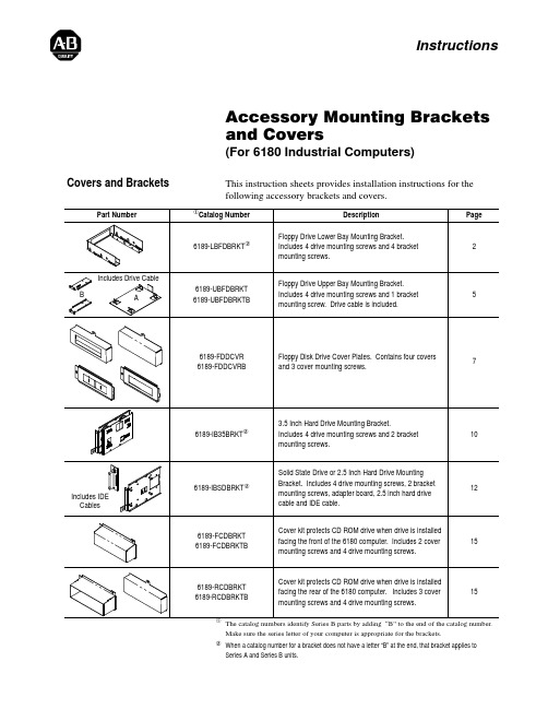
Accessory Mounting Brackets and Covers (For 6180 Industrial Computers)This instruction sheets provides installation instructions for the following accessory brackets and covers.The catalog numbers identify Series B parts by adding “B” to the end of the catalog number.Make sure the series letter of your computer is appropriate for the brackets.y When a catalog number for a bracket does not have a letter “B” at the end, that bracket applies to Series A and Series B units.InstructionsCovers and BracketsAccessory Mounting Brackets and Covers2The lower bay mounting bracket (Catalog No. 6189-LBFDBRKT)allows you to mount a floppy drive facing either the front or the back of the 6180 computer as shown below.•Mounting Bracket for Lower Bay Floppy Drive(Catalog No. 6189-LBFDBRKT for Series A and B)InstallationNote: You can also use these procedures to intstall a front or rear facing CDROM drive (without mounting bracket). The lower bay floppy drive mounting bracket and CDROM drive use the same sets of chassis mounting holes.To install a floppy using the lower bay mounting bracket:1.Secure the floppy drive to the drive bracket using four screwssupplied with the bracket. Tighten screws to a torque of 6-8 in.lbs (.7-.9 N S m).Drive Mounting Screws (4)Floppy Drive Lower Bay Mounting BracketAccessory Mounting Brackets and Covers3!ATTENTION: Remove all cables from the side panel connectors. Failure to remove cables may cause damage to the cables and connectors.!ATTENTION: If the 6180 Computer is installed with mounting clips, the mounting clips on the hinge side will interfere with the opening of the hinge. Remove the mounting clips on the hinge side before swinging chassis away from the bezel. Failure to remove clips may damage clips and the chassis.2.Swing open the back of the computer chassis after removing thethree bezel latching screws. Refer to 6180 computer user manual for instructions if required.From Bezel for Rear Mounting of Drive3.Position the accessory drive / bracket assembly into the chassis.Notes:For rear facing drives, you may have to remove the panelknockout (shown above) if a rear mounted drive was notpreviously installed. Insert screwdriver into slot on knockouts and pry back and forth on knockout to remove. Use a pliers to remove the center rib between the two knockouts.For front facing drives, if a floppy drive was not previouslyinstalled, you may have to replace the floppy drive cover behind the front access door with a cover having an opening. Refer to Floppy Drive Front Cover on page 7 for a description of theavailable covers.Accessory Mounting Brackets and Covers4 4.Connect the cable connectors to the floppy drive. Connectors arekeyed so they cannot be installed backwards.5.Align the floppy drive/bracket (or CDROM) and chassismounting holes and secure the with the 4 mounting screwsprovided with the bracket (or CDROM). Tighten screws to a torque of 6-8 in. lbs (.7-.9 N S m).Use these chassis holes for both rear andfront mounting of a floppy drive. For frontaccess mounting, use the rear hole pairs onthe mounting bracket. For rear accessmounting, use the front hole pairs on themounting bracket.For front access mounting of a CDROM drive, use chassis hole pairs 2 and 5 and the front hole pairs on the CDROM.For Floppy Drive/Bracket AssemblyFor CDROM Drive235For rear access mounting of a CDROMdrive, use chassis holes 3 and the rear holepair on the CDROM.6.Swing the chassis back onto the bezel and secure chassis with thethree latching screws. Tighten screws to a torque of 18-22 inch lbs (2-2.5 N S m).7.Install the back panel.8.Apply power to the 6180 Computer and verify operation of thedrive. You may need to edit BIOS settings to recognize the drive or to allow the operating system to detect the new hardware.Accessory Mounting Brackets and Covers 5The upper bay mounting bracket allows you to mount a floppy driveout the side of the 6180 computer chassis.•Mounting Bracket for Upper Bay Floppy Drive(Catalog No. 6189-UBFDBRKT for Series A; Catalog No.6189–UBFDBRKTB for Series B)InstallationTo install a floppy using the upper bay mounting bracket:1.Secure the floppy drive to the drive bracket using four screwssupplied with the drive. Tighten screws to a torque of 6-8 in. lbs (.7-.9 N S m).Floppy Drive Upper Bay Mounting BracketAccessory Mounting Brackets and Covers62.Remove the back panel to the 6180 computer.3. A shorter drive cable is provided with the mounting kit formounting in the upper bay. Connect the cable to the floppy driveconnector on the processor board (refer to the Processor Boarduser manual if necessary) and the connector on the back of thedrive.4.Position the accessory drive / bracket assembly into the chassis.The edge of the bracket fits under the tab at the front of thechassis.Note: You may have to remove the side panel knockout (shownbelow) if a side mounted drive was not previously installed.Insert screwdriver into slot on knockouts and pry back and forthon knockout to remove. Use a pliers to remove the center ribbetween the two knockouts.!ATTENTION: If knockout is removed, carefully remove any burrs or sharp edges. Failure to remove sharp edges could result in personal injury.5.Align the bracket and chassis mounting hole and secure the drive/ bracket assembly with a mounting screw. Tighten screw to a torque of 6-8 in. lbs (.7-.9 N S m).6.Install the back panel.7.Apply power to the 6180 Computer and verify operation of thedrive. You may need to edit BIOS settings to recognize the drive or to allow the operating system to detect the new hardware.Accessory Mounting Brackets and Covers 7The floppy drive cover plates provide protection for installed floppydrives.•Floppy Drive Cover Plates(Catalog No. 6189-FDDCVR for Series A;Catalog No. 6189-FDDCVRB for Series B)There are four floppy drive cover plates (2 front covers, 2 rearcovers). Use the cover plates as follows:Use this front cover when Floppy Drive is front mounted.The cover mounts under the front access door to protectthe front of the floppy drive.Use this front cover when Floppy Drive is rear mounted ornot installed. The cover mounts under the front accessdoor to protect the rear of the floppy drive or to preventaccess to the inside of the computer.Use this rear cover when front mounting a floppy drive orif a floppy drive is not installed.Use this rear cover when a floppy drive is rear mounted.To install the rear cover plate:1.Remove the back panel to the 6180 computer.2.Position the cover on the inside of the back panel.3.Secure the cover with the screw provided. Tighten screw to atorque of 6-8 in. lbs (.7-.9 N S m).4.Install the back panel on the 6180 computer.Floppy Drive Cover PlatesAccessory Mounting Brackets and Covers8To install a front cover:!ATTENTION: If the 6180 Computer is installed with mounting clips, the mounting clips on the hinge side will interfere with the opening of the hinge. Remove the mounting clips on the hinge side before swinging chassis away from the bezel. Failure to remove clips may damage clips and the chassis.!ATTENTION: Remove all cables from the the side panel connectors. Failure to remove cables may cause damage to the cables and connectors.1.Swing open the back of the computer chassis after removing thethree bezel latching screws. Refer to 6180 computer user manual for instructions if required.From BezelAccessory Mounting Brackets and Covers9 2.Position the front cover inside the front bezel assembly andsecure with the screw provided. Tighten screw to a torque of 6-8 in. lbs (.7-.9 N S m).3.Swing the chassis back onto the bezel and secure chassis with thethree latching screws. Tighten screws to a torque of 18-22 inch lbs (2-2.5 N S m).Accessory Mounting Brackets and Covers10The hard drive mounting brackets allow you to mount a 3.5 inchdrive in one of the drive bays of the 6180 computer chassis.•Mounting Bracket for 3.5 Inch Drives(Catalog No. 6189-IB35BRKT for Series A and B)InstallationTo install a drive using the hard drive mounting bracket:1.Secure the drive to the bracket with the four mounting screws.Tighten screw to a torque of 6-8 in. lbs (.7-.9 N S m).2.Position the drive / bracket assembly into the chassis. Make surethe hook on the bracket slide into the corresponding hole in the chassis. Also make sure that the key on the end of the bracket is inserted into the slot on the chassis front panel.3.Secure the drive / bracket assembly to the chassis with the twomounting screws. Tighten screw to a torque of 6-8 in. lbs (.7-.9N S m).3.5 Inch Hard Drive Mounting Bracket4.Install the ribbon connector on the hard drive. On 3.5 inch drivesalso connect the power cable. Make sure that the ribbon cable is installed correctly. The red wire of the cable must be at thebottom as shown below:5.Install the back panel.6.Apply power to the 6180 Computer and verify operation of thedrive. You may need to edit BIOS settings to recognize the drive or to allow the operating system to detect the new hardware.The solid state drive mounting brackets allow you to mount a 2.5inch or solid state drive in one of the drive bays of the 6180computer chassis.•Mounting Bracket for 2.5 Inch or Solid State Drives(Catalog No. 6189-IBSDBRKT for Series A and B)InstallationTo install a drive using the solid state drive mounting bracket:1.Secure the drive to the bracket with the four mounting screws.Tighten screw to a torque of 6-8 in. lbs (.7-.9 N S m).Important: If you are installing a 2.5 inch drive, you must removethe four standoffs and mount the drive directly to the bracket. Usethe mounting screws provided with the drive.2.Position the drive / bracket assembly into the chassis. Make surethe hook on the bracket slides into the corresponding hole in thechassis. Also make sure that the key on the end of the bracket isinserted into the slot on the chassis front panel.3.Secure the drive / bracket assembly to the chassis with the twomounting screws. Tighten screw to a torque of 6-8 in. lbs (.7-.9N S m).2.5 Inch/Solid State Drive Mounting Brackets4.Install the IDE converter board (provided with bracket) on thetwo standoffs on the left side of the drive bays. The converterboard snaps on to the standoffs, no hardware is required.IDE Converter Board5.Connect the shorter processor board IDE cable (provided withbracket) and power connector to the IDE converter board.IDE Cable From ProcessorBoard Connects HerePower Supply Cable for Drive Connects Here.6.Connect the drive ribbon cable (provided with bracket) to the IDEconverter board and the drive. The red wire of the cable must be at the bottom as shown below:7.Install the back panel.8.Apply power to the 6180 Computer and verify operation of thedrive. You may need to edit BIOS settings to recognize the drive or to allow the operating system to detect the new hardware.The CD ROM covers provide protection for the part of the drive thatextends from the 6180 computer chassis. Two cover kits areavailable:•Cover Kit for Front Mounting of CD ROM(Catalog No. 6189-FCDBRKT for Series A;Catalog No. 6189-FCDBRKTB for Series B)•Cover Kit for Rear Mounting of CD ROM(Catalog No. 6189-RCDBRKT for Series A;Catalog No. 6189-RCDBRKTB for Series B)InstallationNote: There are two bags of screws provided with the bracket. Usethe three flush head mounting screws to mount the covers. Use theremaining four screws to secure the CD ROM drive.Use this front cover when a CD Drive is rear mounted.The cover mounts under the front access door to protectthe rear of the CD drive.Use this rear cover when a CD Drive is rear mounted.The cover mounts to the back panel to protect the front ofthe CD drive while allowing access to the drive.Catalog No. 6189-RCDBRKTCatalog No. 6189-RCDBRKTBCatalog No. 6189-FCDBRKTCatalog No. 6189-FCDBRKTB Use this rear cover when a CD Drive is front mounted.The cover mounts on the back panel to protect the rearof the CD drive.To install a rear cover:1.Remove the back panel to the 6180 computer.2.Position the cover on the inside of the back panel.3.Secure the cover with the screw provided. Tighten screw to atorque of 6-8 in. lbs (.7-.9 N S m).4.Install the back panel.To install a front cover , refer to the instructions on page 8.To install a CD ROM , refer to the instructions on page 4.CD ROM CoversAllen-Bradley, a Rockwell Automation Business, has been helping its customers improveproductivity and quality for more than 90 years. We design, manufacture and support a broadrange of automation products worldwide. They include logic processors, power and motioncontrol devices, operator interfaces, sensors and a variety of software. Rockwell is one of theWorldwide representation.Argentina • Australia • Austria • Bahrain • Belgium • Brazil • Bulgaria • Canada • Chile • China, PRC • Colombia • Costa Rica • Croatia • Cyprus • Czech Republic • Denmark •Ecuador • Egypt • El Salvador • Finland • France • Germany • Greece • Guatemala • Honduras • Hong Kong • Hungary • Iceland • India • Indonesia • Ireland •Israel • Italy •Jamaica • Japan • Jordan • Korea • Kuwait • Lebanon • Malaysia • Mexico • Netherlands •New Zealand • Norway • Pakistan • Peru • Philippines • Poland • Portugal • Puerto Rico • Qatar • Romania • Russia–CIS • Saudi Arabia • Singapore • Slovakia • Slovenia • South Africa, Republic • Spain • Sweden •Switzerland • Taiwan • Thailand • Turkey •United Arab Emirates • United Kingdom • United States • Uruguay • Venezuela • YugoslaviaAllen-Bradley Headquarters, 1201 South Second Street, Milwaukee, WI 53204 USA, Tel: (1) 414 382-2000 Fax: (1) 414 382-444441061-042-01(D)Copyright 1998 Allen-Bradley Company, Inc. Printed in USA。
曙光DS800-G35系列磁盘阵列用户手册V1.0
3
分支电路负载过高在某些情况下可能导致火灾和电击危险。为避免这些危险,请确保系统电气要求未超出分支电路 保护要求。请参阅设备随附的信息以了解电气规范。
在通电的服务器内部进行操作
服务器通电时,释放到服务器内部组件的静电可能导致服务器异常中止,这可能会造成数据丢失。要避免出现这一 潜在问题,在通电的服务器内部进行操作时,请始终使用静电释放腕带或其他接地系统。服务器(某些型号)支持 热插拔设备,并且设计为在服务器开启及外盖卸下时可安全运行。对开启的服务器内部进行操作时,请遵守以下准 则。
对于您在本产品之外使用本产品随机提供的软件,或在本产品上使用非随机软件或经曙光公司认证推荐使用的专用 软件之外的其他软件,曙光公司对其可靠性不做任何保证。
曙光公司已经对本手册进行了仔细的校勘和核对, 但不能保证本手册完全没有任何错误和疏漏。 为更好地提供服务, 曙光公司可能会对本手册中描述的产品软件和硬件及本手册的内容随时进行改进或更改,恕不另行通知。如果您在 使用过程中发现本产品的实际情况与本手册有不一致之处,或您想得到最新的信息或有任何问题和想法,欢迎致电 400-810-0466 或登录曙光公司服务网站 垂询。
2
【
】
本产品为 A 级产品。在生活环境中,该产品可能会造成无线电干扰。在这种情况下,可能需要用户对干扰采取切实 可行的措施。
电源、电话和通信电缆中的电流具有危险性。为避免电击危险: 请勿在雷电期间连接或断开本产品的任何电缆,也不要安装、维护或重新配置本产品。 将所有电源线连接至正确接线且妥善接地的电源插座。 将所有要连接到本产品的设备连接到正确接线的插座。 尽可能仅使用单手连接信号电缆或断开信号电缆的连接。 切勿在有火灾、水灾或房屋倒塌迹象时开启任何设备。 除非在安装和配置过程中另有说明,否则请在打开设备外盖之前断开已连接的电源线、远程通信系统、网络和调 制解调器。
SUN服务器RAID配置

北京四达时代前端事业部朱海清2011-11-10SUN服务器RAID制作方法带硬件RAID控制器的SUN服务器都可以使用此方法,T系列的全都可以。
1、光盘引导进入单用户模式,进入#提示符模式下{0} ok boot cdrom -sbash-3.2# raidctlController: 1Volume:c1t0d0Disk: 0.0.0Disk: 0.1.0Disk: 0.2.02、指定需要做RAID1的两块盘的标识符,然后使用raidctl命令创建命令格式:raidctl -C "disks" [-r raid_level] controller举例:# raidctl –C ”0.0.0 0.1.0 0.2.0”–r 0 1命令的含义:控制器1上创建raid0# raidctl -C "0.0.0 0.2.0" -r 0 0命令的含义:控制器0上创建raid0# raidctl -C "0.0.0 1.1.0" -r 1 2命令的含义:控制器0上创建raid0# raidctl -l c1t0d0命令的含义:查看卷c1d0d0上raid的状态# raidctl –a set –g 0.3.0 2# raidctl -C "0.0.0 0.1.0 0.2.0" -r 5 2命令的含义:指定0.3.0为2号控制器上的热备盘,并在2号控制器上创建raid53、创建完成后,重新进入单用户模式下,并切换到光盘引导,开始系统安装。
此时系统会一边安装一边进行同步。
# init 0# syncing file systems... doneProgram terminated{0} ok boot cdrom。
SUN存储产品介绍

6580 (Base) *
~ 600,000 IOPS ~ 115,000 IOPS ~ 30,000 IOPS
~ 3,200 MB/s ~ 3,000 MB/s ~ 2,800 MB/s ~ 2,500 MB/s FSW ~ 2,000 MB/s
6780 H (High) *
~ 700,000 IOPS ~ 172,000 IOPS ~ 45,000 IOPS
CSMII或者CSM200 – 交换式磁盘模块
• 基本信息
> RoHS compliant > 4Gb/s的光纤接口 > 支持16 HDD
• 增强的诊断
> 驱动器的孤立和point-to-point的通信使得CSMII提供增 强的信息来帮助标识和故障解决错误的磁盘或者线 缆
• 改良的可靠性/可用能力
• 8 GB, 16 GB, 32GB 数据缓存 • 64GB 数据缓存将在夏季推出 • 8 或者16个 8Gb/s FC 主机端口 • 20块SSD • 可扩展到 448 块盘 共28 个磁盘柜, 每个16 块盘
• 支持磁盘加密(FDE)
© 2010 Oracle and/or its affiliates. All rights reserved.
Virtualization Strategy Stripe
Stripe
Concatenate
Stripe Size (DSP)
1 MB
2 MB
128 KB
© 2010 Oracle and/or its affiliates. All rights reserved.
19
适应性
Non-Disruptive Changes
Sun StorageTek 6140磁盘阵列配置手册

一、Sun磁盘阵列管理软件的安装1. 首先下载Sun StorageTek Common Array Manager(Sun存储通用阵列管理器) 软件,这里使用的版本是6.4.1.52. 将压缩包解压到c盘根目录下,解压后的文件如下:3. 在Dos命令行模式进入解压后的文件夹,运行上面的批处理命令:RunMe.bat –c4. 在弹出的对话框中, 按1选择下一步。
5. 选择接受许可协议。
6.选择所需要的安装类型,这里选择”典型安装”。
7. 选择下一步,继续安装。
8. 稍等片刻,安装需要一定时间。
二、使用CAM软件连接磁盘阵列9.安装结束以后,使用交叉线连接到ST6140的控制器A的第一个网络管理端口(默认IP:192.168.128.101),然后在windows管理端的IE浏览器输入:https://localhost:6789登录,跳转到如下界面。
在对话框中输入当前主机的登录用户名和密码,这里使用的是administrator 。
10. 进入页面点击Sun StorageTek(TM) Common Array Manager11. 注册存储系统12. 输入需要连接的盘阵的IP地址,这里缺省的是192.168.128.101 / 102 ,密码选择使用默认密码。
( 盘阵的默认密码一般为kra16wen )13.显示已经搜索到的盘阵,点击“完成”进行盘阵的连接。
挂载的硬盘的详细信息。
、15. 选择物理设备> 控制器,可以查看并修改盘阵控制器上的以太网卡的IP地址和网关等参数。
二、磁盘阵列Raid的划分1. 对阵列中的磁盘进行Raid的划分。
首先要在Unlabeled > 配置文件中新建一个存储配置文件。
2. 为配置文件任意起一个名称,RAID级别可供选择的有raid0、raid1、raid3、raid5、raid6,这里我们选择raid0,段大小选择64k,数量编号,需要几块硬盘做raid就选几块,磁盘类型根据实际情况选择。
海康监控磁盘阵列怎么配置?一文了解清楚
海康监控磁盘阵列怎么配置?⼀⽂了解清楚前⾯我们曾发布过raid1 raid2 raid5 raid6 raid10如何选择使⽤?各需要⼏块硬盘,有不少的朋友问到了关于磁盘阵列的如何配置,这个确实是个实际问题,在项⽬中也常遇到,之前我们没有提过到这⽅⾯的内容,本期我们⼀起来看下如何配置磁盘阵列,以海康监控系统为例。
磁盘阵列怎么配置,有两种⽅式:1、⼀键⾃动配置2、⼿动配置我们来详细看下分别如何配置。
⼀、⼀键配置阵列⼀键配置默认创建的阵列类型为RAID5。
具体步骤如下:步骤1:选择'主菜单→硬盘管理→阵列配置',进⼊阵列配置的'物理磁盘'界⾯注意:1)⼀键配置的阵列类型为RAID 5,⾄少需安装3 块物理磁盘。
2)当使⽤4 个及以上物理硬盘⼀键配置时,默认创建⼀个RAID5 和1 个热备盘(推荐设置热备盘,以保证阵列异常时,⾃动开始重建)。
步骤2:单击'⼀键配置',进⼊'⼀键配置阵列'界⾯步骤3:输⼊阵列的名称,单击'确定',开始创建阵列。
创建成功,弹出'⼀键配置阵列成功'提⽰信息。
步骤4:查看阵列创建的情况。
选择'阵列'属性页,进⼊阵列配置的'阵列'界⾯,如图所⽰。
可查看⼀键创建阵列的容量、阵列类型、热备盘等信息。
步骤5:查看磁盘信息。
选择'主菜单→硬盘管理→基本配置',进⼊'基本配置'界⾯。
查看磁盘状态。
设备将⾃动初始化创建的磁盘,当初始化完成,状态显⽰为'正常'。
注意:⾃动初始化磁盘完成后,磁盘才能进⾏正常读写。
⼆、⼿动创建阵列步骤1:选择'主菜单→硬盘管理→阵列配置',进⼊阵列配置的'物理磁盘'界⾯步骤2:选择需要创建配置的物理磁盘,单击'创建阵列',进⼊'创建阵列'界⾯步骤3:输⼊阵列的名称,设置阵列类型为RAID5。
磁盘阵列技术参数要求

磁盘阵列技术参数要求推荐品牌:EMC, 宝德,OKSTOR带“★”为必须满足的技术参数技术参数要求存储阵列支工业化标准的系统平台,Windows Server 2008 / 2008 R2 /2012,Windows Hyper-V, Red Hat EnterpriseLinux, SUSE Linux Enterprise, Sun Solaris, Mac OS X, HP-UX, IBM AIX, VMware, Citrix XenServer★存储系统必需采用全新的并发结构(网格结构),即每存储模块或节点都必须自带控制器。
所有老式的中央控制器管理整套存储系统所有盘柜和功能的存储系统,一概不会考虑。
★标配16个SAS/SATA/SSD磁盘通道,最大扩展数量316★控制器采用64bit高性能存储冗余控制器,支持Active/Active、故障复原/自动恢复、多路径负载均衡机制,弹性化的控制器工作状态,采用XOR硬件校验芯片和带有ECC数据校验功能的高速缓存单柜支持16盘位,最大裸容量支持64TB SAS存储空间★存储阵列必须同时支持2.5寸、3.5寸的SAS、SATA、SSD三种硬盘存储阵列必须支持精简配置(thin provisioning),实现空间利用的高效性,该功能无容量的限制★自动重建、在线添加驱动器和更换大容量驱动器复制和替换源驱动器来扩充存储空间、S.M.A.R.T.硬盘智能检测、在高负荷情况下对硬盘的性能和稳定性进行优化、自动坏扇区调整、数据块可靠性验证和修复存储阵列在进行容量扩展、节点增加时,无需为数据存储配置任何额外收费的软件许可针对企业数据中心以及具备大量、高成长性数据的存储应用环境,提供弹性化的数据管理、保护、扩充性及安全性存储阵列要求无单点故障,包括存储节点/控制器为确保性能,存储阵列确保每个控制器控制的硬盘数量不超过12块,每控制器包含两个iSCSI端口★RAID Level 0, (0+1), 3, 5, 6, 10, 30, 50, 60,全局、本地、箱体热备模式;在线增加新硬盘,复制、更换大容量硬盘;RAID迁移和自动降级存储阵列提供数据快照与克隆技术,提供全容量的软件许可,当存储空间增加时,无需对快照和克隆软件增加许可★存储系统必需内含不低于2TB eMLC级别 SSD盘,并内含SSD 到HDD的热点数据迁移软件,如自动分层等,来达到提高IOPS的目标存储阵列提供的虚拟克隆技术无需占用额外存储空间,同时支持基于精简配置(Thinprovisioning)的数据快照与克隆技术每个卷支持创建超过1000个数据快照存储阵列支持同步和异步数据复制,并且数据复制功能为全容量的免费使用提供基于存储阵列的原卷到目标卷的远程数据容灾,数据复制时目标端占用的空间为真实的数据空间,无需额外对目标卷进行空间划分支持端口整合(Link Aggregation)、巨型封包功能(Jumbo Frames)、SMB/CIFS、NFS、FTP、Microsoft ADS,内建I/O效能及电源使用量监视功能存储阵列支持与服务器之间进行远程复制,提供远程分支机构的数据保护能力★内置WebGUI、LCD、串口、Telnet、SSH、第三方的SNMP 及CIM管理软件★本次配置容量:12* 2TB SATA 7,200转3.5寸硬盘★原厂3年质保,需原厂针对本项目授权书和售后服务器承诺函★免费安装调试1推荐品牌:Time Navigator,Acronis, EMC带“★”为必须满足的技术参数★备份软件的备份服务器端(Server端)支持多种主流操作系统,包括:HP-UX、Tru64、IBM AIX、SUN Solaris、SGI Irix、Mac OS、Windows和Linux平台备份软件客户端(Agent端)支持多种主流操作系统,包括:HP-UX、Tru64、IBM AIX、AS400、SUN Solaris、SGI Irix、SCO UNIX、VMS、Netware、Mac OS、VMware(ESX、VMFS)、Windows (XP、NT、2000、2003)、Linux虚拟化环境支持:VMware、Hyper-V、Citrix XEN★支持基于图形化的数据库联机备份,包括:Oracle、DB2、Sybase、Informix、SQL Server、My SQL 、MaxDB支持基于图形化的MS Exchange 、MS SharePoint、Lotus Notes等应用的联机备份支持GUI管理界面,支持基于WEB的远程管理和查询功能集中化管理多个备份环境,可远程分发备份客户端软件★提供在UNIX、Linux、Windows以及Mac OS等不同操作系统下一致的图形化安装和管理界面产品许可管理模块化,不限制CPU、不限主机型号★支持网络备份和SAN架构下的LAN-Free和Serverless备份★在SAN结构下,允许不同操作系统共享磁带库设备,同一磁带驱动器可被同一或不同操作系统的主机动态共享,支持各种主流的磁带库产品,支持标准的tar、cpio等备份格式★支持磁带规整及磁带重用技术,最大限度的节省存储介质支持对备份介质的全面管理,包括:磁带自动标签、磁带信息的自动一致性同步、标记出错磁带等支持对于磁带库运行状况的实时监控支持简单方便地对备份系统进行管理,支持查询、统计、报告、图表的分析和导出功能支持灵活备份策略的定制,包括:全备份、增量备份、合成全备份、归档等多种备份方式,并且针对不同的备份方式提供不同的备份策略、支持备份策略规则的共享具备报表系统,能够根据需要对其管理的各项任务、各类数据、各个主机、各种介质等信息进行统计,并生成电子报表★具备图形界面的审计功能,对备份恢复的各种操作,从时间、用户名、操作记录等多方面监控支持在特定情况下由用户触发的手动或脚本触发的自动备份支持基于日历的策略制定,如设置非工作时间、排除节假日等备份计划支持备份作业生命周期的自动化管理,即可控制备份作业的执行时间,避免由于备份时间窗口过长从而对生产系统造成不良影响数据库及文件系统的断点持续备份、跨主机恢复支持不同级别的用户权限控制,包括管理员级别和普通监控用户级别★单一端口的跨防火墙备份恢复和管理支持私有、可加密的磁带格式、支持备份数据的128位加密支持X509、PKCS协议支持NDMP Data Server、NDMP Agent以及NDMP Tape Server,支持NDMP Serverless Backup和NDMP 协议的单个实例恢复★备份软件内置虚拟磁带库功能,支持任何类型的磁盘(SCSI、SATA、IDE、SAN),提供自动化的磁盘-磁盘-磁带的数据迁移功能★虚拟磁带库的容量大小不受限制★备份容量无限量,容量扩增无需额外License许可收费★备份服务器模块3个备份客户端模块TINA VLS(虚拟磁带库模块) Tape Driver connection(磁带库驱动器连接模块)23个点数据库模块,支持数据库:DB2,Oracle ,Informix,Sybase,SQL Server。
(完整版)阵列服务器配置要求
阵列服务器配置要求一、一台磁盘阵列,配置如下:平均传输率(MB/s) 200高速缓存512MB平均无故障时间(MTBF)500000小时以上操作系统支持Windows /2000/2003外接主机通道2 X 1Gb iSCSIRAID支持0,1,3,5,10单机磁盘数量(个) 14内置硬盘接口Ultra 3 SCSI,SATA其他规格认证CE,FCC电源及功率AC 220V双冗余,热交换电源冗余风扇扩展磁盘柜相关配件及其他附件容量8T二、一套虚拟主机软件,配置如下:◇WEB服务软件:IIS、Apache◇FTP上传软件:Serv-U、pureFTP◇邮局服务软件:IMAIL、WEBMAIL◇数据库软件:MSSQL、MySQL◇DNS服务软件:Win自带的DNS服务、MyDNS、本公司的WinMyDNS◇支持脚本:asp,,php,cgi,jsp等所有可在iis或apache下运行的脚本◇虚拟主机在线开通、删除、修改、升级◇MSSQL数据库在线开通、删除、修改、升级◇MySQL数据库在线开通、删除、修改、升级◇支持四家邮局在线开通、删除、修改、升级◇独立虚拟主机控制面板,支持域名绑定、设置默认首页、修改FTP密码、WEB上传、修改MSSQL密码、修改MySQL密码、自定义404等错误页面、脚本错误信息设置、修改邮局密码、Web 日志下载、ASP脚本加密、文件解压缩◇独立的主控端WEB服务器集中管理平台◇支持服务器集中监控◇所有服务器IIS及FTP保中自动备份及恢复◇所有服务器的IIS、FTP、MSSQL、MySQL、DNS、NT帐户、NT文件夹集中WEB管理功能单位:南京师范大学教务处联系人:鄢放83598787。
海康威视磁盘阵列使用说明

海康威视磁盘阵列使用说明一.登录1.存储系统默认登录账户为:web_admin 密码为:1232.登录时应以高级模式登录二.设定IP SAN的访问IP管理员可以通过与存储设备相互连通的网络,来设置IP SAN的访问IP。
存储设备分为管理网口和数据网口,可以通过管理网口或者数据网口连接管理PC连接管理网口后,用户可以将用来进行存储管理的设备IP改为同网段的IP,确认网络连接正常后,便可以在IE中输入:https://192.168.10.138:2004来登录IP SAN的管理界面。
一.网络配置下图是系统正常登录后的界面,如图1所示图11.进入系统后,可以首先进入网络管理,在进入网络管理界面后首先要进行网口绑定:点击“绑定管理”按钮,在弹出的界面选择要绑定的网口且绑定模式为“虚拟化”,在点击“创建绑定”并确认绑定成功2.接下来就是“网口管理”,网口管理即就是修改系统IP地址,进入网口管理界面如图2所示:可在此修改系统的访问IP地址图2二.创建RAID1.网络管理之后就是RAID管理,首先要创建阵列,进入“阵列创建”界面,如图3所示图3输入阵列名称,并将阵列类型选为RAID5,然后在可用物理盘中勾选至少3块盘创建阵列,选好后点击“创建阵列”即可。
2.第二步则要进行“阵列重构”,阵列重构是对于已经存在的阵列中,某个物理盘出现不稳定或者出现故障的情况下,为了拯救出故障硬盘中的数据而设定的,从而达到保护数据和恢复阵列的完整性。
但,前提是系统中存在可用的物理盘,并且和出故障的硬盘容量大小相同。
如图4所示图4初始时候阵列自动重构状态默认是关闭的,首先我们要开启自动重构然后输入阵列名称并选择1块可用物理盘,点击“重构阵列”(阵列重构一般是在有故障盘的时候才会用到)3.接下来就要进入“热备盘管理”,热备盘是用来防止阵列中出现掉盘或者磁盘出故障时及时自动化去替换出现故障的硬盘。
其界面如下图5 选择要添加的热备盘点击“添加热备盘”即可图54.之后就是阵列校验,阵列校验的目的是预先防止数据存储过程中出现的错误和长期读写造成的文件丢失,从而达到数据的有效性和完整性。
- 1、下载文档前请自行甄别文档内容的完整性,平台不提供额外的编辑、内容补充、找答案等附加服务。
- 2、"仅部分预览"的文档,不可在线预览部分如存在完整性等问题,可反馈申请退款(可完整预览的文档不适用该条件!)。
- 3、如文档侵犯您的权益,请联系客服反馈,我们会尽快为您处理(人工客服工作时间:9:00-18:30)。
北京四达时代软件技术股份有限公司SUN磁盘阵列的配置和管理基于Sun Storage 6180和Sun Storage Common Array Manager软件前端事业部:朱海清11/10/2011Beijing Startimes Software Technology Co.,LtdContents一、前情提要 (2)二、磁盘阵列和SUN主机的物理连接 (2)1、光纤连接 (2)2、网线连接 (3)3、串口连接 (3)三、安装Sun Storage Common Array Manager(CAM) (5)1、获取CAM (5)2、安装CAM (5)四、配置磁盘阵列 (8)1、打开浏览器 (8)2、实战RAID5 (15)3、实际划卷效果 (27)4、磁盘同步 (28)五、配置SUN主机 (29)1、查看磁盘阵列映射信息 (29)2、多路径聚合 (30)3、label磁盘,并分配卷名 (32)4、写入vfstab (39)Beijing Startimes Software Technology Co.,Ltd 一、前情提要本文主要内容是介绍如何将盘阵物理连接到主机,使用Sun Storage Common Array Manager6.7配置盘阵,并将盘阵挂载到SUN主机。
二、磁盘阵列和SUN主机的物理连接1、光纤连接A、SUN主机1个HBA卡,磁盘阵列2个控制器HBA的PORT1连接到控制器1的PORT1HBA的PORT2连接到控制器2的PORT1B、SUN主机2个HBA卡,磁盘阵列2个控制器HBA1的PORT1连接到控制器1的PORT1HBA1的PORT2连接到控制器2的PORT1HBA2的PORT1连接到控制器1的PORT2HBA2的PORT2连接到控制器2的PORT2C、SUN主机1个HBA卡,磁盘阵列1个控制器HBA的PORT1连接到控制器1的PORT1HBA的PORT2连接到控制器1的PORT2Beijing Startimes Software Technology Co.,Ltd 2、网线连接网线主要是用来配置并管理磁盘阵列的,使用本文中的Common Array Manager或者telnet连接,实际系统上线后,可以将网线拆除。
盘阵的每个控制器都有2个以太网口(PORT1和PORT2)新盘阵控制器的默认网卡地址:控制器1 - PORT1:192.168.128.101控制器1 - PORT2:192.168.129.101控制器2 - PORT1:192.168.128.102控制器2 - PORT2:192.168.129.102如果只有1个控制器,一般默认1号口的地址不是192.168.128.101,就是192.168.128.102。
只要把笔记本配成同一网段,既可以开始连接。
3、串口连接每个控制器上都有1个圆形的串口(样子类似于PC机上的PS2口,需要用SUN盘阵自带的圆形接头串口线)。
这个口貌似只能用来查看并修改控制器的IP。
A、按Break 键。
阵列串行端口要求接收断开字符。
请使用您终端设置所适用的转义序列向阵列控制器发送必需的断开字符。
例如,通过同时按下Ctrl 键和Break 键在某些终端上生成断开字符。
作为响应,盘阵的串行端口会发出一个与终端的波特率进行同步的请求,也就是说你的笔记本什么波特率都行,盘阵会与你保持一致:Set baud rate: press <space> within 5 secondsBeijing Startimes Software Technology Co.,Ltd B、按住空格键五秒钟。
串行端口将确认为连接建立的波特率:Baud rate set to 9600C、按Break 键串行端口将用以下消息进行响应:Press within 5 seconds: <S> for Service Interface, <BREAK> for baud rateD、按S 键以访问"Service Interface" 菜单注意是大写的S,按的时候可以是shift+s,或者把caps lock打开。
串行端口将提示输入串行端口密码:Enter Password to access Service Interface (60 sec timeout):E、键入串行端口默认密码默认密码为:kra16wen,然后按Enter 键。
屏幕上将显示"Service Interface" 菜单。
Service Interface Main Menu==============================1) Display IP Configuration2) Change IP ConfigurationBeijing Startimes Software Technology Co.,Ltd3) Reset Storage Array (SYMbol) PasswordQ) Quit MenuEnter Selection:三、安装Sun Storage Common Array Manager(CAM1)1、获取CAMSUN被ORACLE收购之后,这个软件无法在ORACLE网站上直接下载得到了,需你要取得ORACLE的支持帐号,然后登录才能下载得到,最新版本的是6.8。
需要的童鞋到公司ftp去下载吧,但是是6.7版本的,大小为560多兆。
2、安装CAMA、删除本机已有的JAVA环境变量配置,否则会安装失败:JAVA_HOMEEXE4j_JAVA_HOMEPATH中的d:\jdk1.5_22\bin(依据你本机的实际配置)PATH变量中类似d:\jdk1.5_22\bin的配置B、解压软件包,得到HostSoftwareCD_6.7.0.12目录,进入该目录并执行RunMe.bat,一路下一步,直到安装完毕。
注:卸载方法:进入HostSoftwareCD_6.7.0.12\bin目录,执行uninstall.bat -f1CAM是Common Array Manager的简称,同下文。
Beijing Startimes Software Technology Co.,LtdBeijing Startimes Software Technology Co.,Ltd安装完成Beijing Startimes Software Technology Co.,Ltd四、配置磁盘阵列1、打开浏览器在地址栏中输入https://127.0.0.1:6789,忽略浏览器的安全证书警告,出现Oracle Java Web Console登录界面,输入登录用户名和密码注:用户名和口令为你笔记本操作系统当前用户的用户名和口令。
Beijing Startimes Software Technology Co.,Ltd 1、点击Sun Storage Common Array Manager(蓝色字体)Beijing Startimes Software Technology Co.,Ltd2、如果你是在本机首次使用Sun Storage Common Array Manager,则进入页面后,系统会提示输入注册信息,随便输(带红色星号的空格)就可以了,然后点击保存并继续按钮(Save and Continue Setup)。
Beijing Startimes Software Technology Co.,Ltd3、注册信息输入完毕后,接下来的页面会提示设置ASR自动服务请求(Auto Service Request),这是个付费功能,且需要SUN支持帐号,用于当盘阵出现问题时,SUN可以自动提供解决方案。
如果咱们没有,就直接点击拒绝(Decline)按钮吧。
4、到了盘阵注册界面,点击Register按钮,注册盘阵,在弹出的界面中输入盘阵的控制器IP,然后点击下一步。
你也可以直接选择第一个选项:扫描本地网络,让程序去自动发现盘阵,只不过那样耗费的时间会比较长。
Beijing Startimes Software Technology Co.,Ltd 5、开始查找盘阵Beijing Startimes Software Technology Co.,Ltd 6、找到盘阵了,点击完成按钮Beijing Startimes Software Technology Co.,Ltd7、系统开始自动在本机注册并缓存所连接磁盘阵列的信息。
完成之后,点击关闭按钮就可以了。
这个过程中,可能会有关于基准固件(firmware baseline)的告警,一般都是因为盘阵的控制器固件比CAM自带的盘阵固件版本低。
你有2个选择:忽略或者升级安装新固件。
如果选择刷新固件,请确保盘阵的状态未处于降级状态(degrade),否则会损坏盘阵,但是如果阵列仅仅因为未达到基准而处于降级状态而降级,则可以忽略,并执行升级操作,请自己在操作过程中仔细查看告警的详细内容再做决定。
升级过程完全在本地进行,不需要上网下载,因为CAM本身自带固件文件。
具体的固件目录为C:\Program Files\Sun\Common Array Manager\Component\SunStorageTekArrayFirmwareBeijing Startimes Software Technology Co.,Ltd8、注册完成完成盘阵注册之后,磁盘的信息就会出现在刚才Storage System Summary界面中下图的unlabeled是盘阵默认给自己指定的名字,具体你可以到Storage Systems->Administrator菜单中修改。
2、实战RAID5A、实施要求磁盘阵列配置6块硬盘,并准备配置为RAID5。
给磁盘分2个LUN,一个给ORACLE数据库存放表空间文件用,一个给SUN Cluster做决策盘(1G左右)。
Beijing Startimes Software Technology Co.,Ltd B、指定热备盘先到Storage Systems->Physical Devices->Disks中指定一块热备盘(Hot-Spare):点击某一块磁盘的名字,进入页面后,点击顶部的“Assign Hot-Spare”按钮完毕,按钮上的文字会变成“Unassign Hot-Spare”。
Beijing Startimes Software Technology Co.,Ltd 回到Disks菜单,该磁盘的角色已由Data Disk变成Array SpareC、划分oracle数据盘进入Storage Systems->unlabeled->Volumes点击新建按钮,开始配置磁盘阵列。
