FM-800-026 (1.0) 年度精密量测计划表
收音频率范围测试规范附表
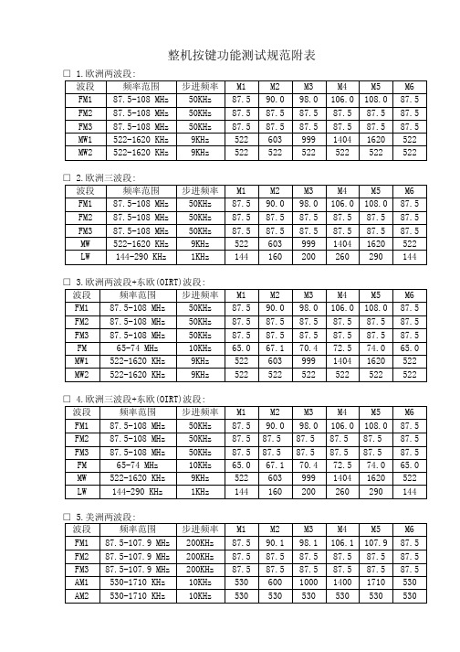
M6 87.5 87.5 87.5 522 144
□ 3.欧洲两波段+东欧(OIRT)波段: 波段 频率范围 步进频率 FM1 87.5-108 MHz 50KHz FM2 87.5-108 MHz 50KHz FM3 87.5-108 MHz 50KHz FM 65-74 MHz 10KHz MW1 522-1620 KHz 9KHz MW2 522-1620 KHz 9KHz □ 4.欧洲三波段+东欧(OIRT)波段: 波段 频率范围 步进频率 FM1 87.5-108 MHz 50KHz FM2 87.5-108 MHz 50KHz FM3 87.5-108 MHz 50KHz FM 65-74 MHz 10KHz MW 522-1620 KHz 9KHz LW 144-290 KHz 1KHz □ 5.美洲两波段: 波段 频率范围 FM1 87.5-107.9 MHz FM2 87.5-107.9 MHz FM3 87.5-107.9 MHz AM1 530-1710 KHz AM2 530-1710 KHz
M6 87.5 87.5 87.5 65.0 522 522
M1 87.5 87.5 87.5 65.0 522 144
M2 90.0 87.5 87.5 67.1 603 160
M3 98.0 87.5 87.5 70.4 999 200
M4 106.0 87.5 87.5 72.5 1404 260
M4 106.0 87.5 87.5 1395 522
M5 1 87.5 522 522
步进频率 50KHz 50KHz 50KHz 9KHz 1KHz
M1 87.5 87.5 87.5 522 144
M2 90.0 87.5 87.5 603 160
常用测量仪器设备精度表

14
多波束8125
频率:455HZ
波束数:240
波束角:°x1°
覆盖宽度:x水深 测深分辨率:6mm
测深范围:3.5m-120m
美国
15
多波束2024
频率:200HZ--400HZ可选 波束数:256
波束角:°X1°(400HZ) 1°X2°(200HZ)
覆盖宽度:10°X160°可选
测深分辨率:1.25mm
测深范围:3.5m-500m
美国
16
旁扫声纳Klein
3000
水平:500F赫兹,21度
100千赫兹,7度
垂直:40度
倾斜:向下倾余5 10, 15 20或25度,可调整
预计声纳范围100千赫兹:50(米
500千赫兹:150米
美国
17
STEMA
DENSITUNE
泥浆密度仪
剪应力强度范围:0—200Pa
单次测量时间?一般3s??
望远镜放大倍率?24x?
补偿器?-?
类型?磁性阻尼补偿器?
补偿范围?±10'?
精度?0.3”
工作温度?:-20C到?+50C?
26
全站仪Leica
TPS1200
角度测量--
精度:1”(Hz,V)
补偿器:"(设置精度)
4'(补偿范围)
距离测量一
测程:3000m(圆棱镜)
1200m(小棱镜)
英国
24
水准仪Leica
NA2
往返测高程精度?:
0.7mm?/km
0.3mm/km?(带测微计)?
放大倍率?:标准32x,FOK73?!镜(可选)?40x,FOK117?目镜(可
射频导纳说明书

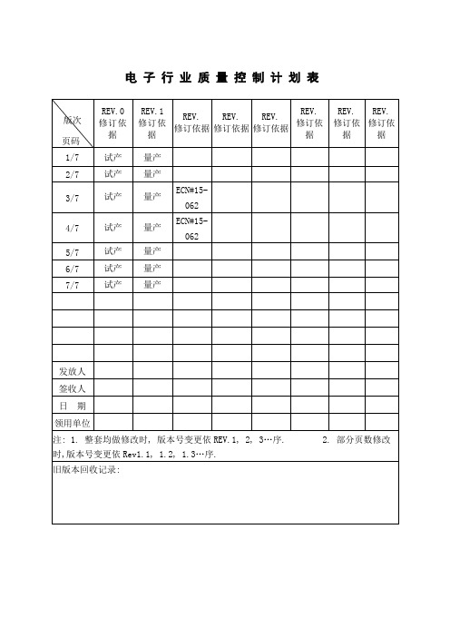
电子行业质量控制计划表
矫正措施
贴铭板 &装脚
垫 302-06
静电 环,手
套
脚垫规格 贴铭印 字,内容
依作业
指导书
!
工程蓝 图
目视
首件 5PCS/2H
F017
重贴
贴 LB 302-07
静电 环,手
套
LB 印字, 内容
依作业 指导书 工程蓝
图
目视
首件 5PCS/2H
F017
重贴
外观检 静电 查 环,手
302-08 套
CASE 规 格,外观
纸盒贴 LB&折 纸盒 302-09
静电 环,手
套
纸盒规格
静电
折纸卡 302-10
环,手 套
纸卡规格
装纸盒 302-11
静电 环,手
套
放说明 书&螺
丝 302-12
静电 环,手
套
!
依 BOM 清单 作业指 导书
目视 卡尺 量测
首件 5PCS/2H
F017
重工或报废
依作业 指导书
目视
首件 5PCS/2H
依作业指导书 330±30℃
依作业指导书 380±30℃
测温 器量 测
1
次/4H
F026
调整或更 换烙铁
治具 量测
首件 5PCS/2H
F017
自主修理
目视
首件 5PCS/2H
F017Biblioteka 自主修理测温 器量 测1 次/4H
F026
调整或更 换烙铁
目视
首件 5PCS/2H
F017
自主修理
测温 器量 测
1 次/4H
F017
监视和测量表单(电子)(1)
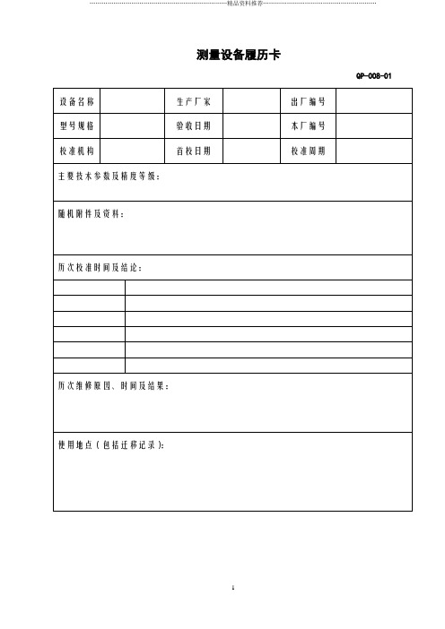
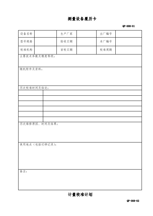
QP-008-01
设备名称
生产厂家
出厂编号
型号规格
验收日期
本厂编号
校准机构
首校日期
校准周期
主要技术参数及精度等级:
随机附件及资料:
历次校准时间及结论:
历次维修原因、时间及结果:
使用地点(包括迁移记录):
备注:
计量校准计划
QP-008-02
序号
设备编号
设备名称
使用部门
计划校准日期
校准机构
一年
29
GX-JCS-029
大功率灯珠老化测试仪
品质部
2011.01.03
宝世达电子
1个月
30
GX-JCS-030
贴装灯珠老化测试仪
品质部
2011.01.03
宝世达电子
1个月
31
GX-JCS-031
直插灯珠老化测试仪
品质部
2011.01.03
宝世达电子
1个月
32
GX-JCS-032
接地电阻测试仪
品质部
AR3520(-50-480℃)
1
品质部
深圳欣宝瑞科技
闲置设备
15
GX-JCS-015
电子称
JGC-30756(0-30kg)
1
品质部
福州科迪电子
内校
16
GX-JCS-016
塞尺
0.01-1cm
5
品质部
上海惠申金属制品
内校
17
GX-JCS-017
多路直流稳流稳压电源
RYI6003-3D(0-50V/3A)
多路直流稳流稳压电源
品质部/生产部
2010.06.07
Aeroflex MLS-801 微波着陆系统斜面测试设备说明书

MLS-801T h e M L S-801r a m p t e s t s e t p r o v i d e s M i c r o w a v e L a n d i n g S y s t e m a n g l eBEAM LEVELFixed at 6 dB above the preamble; Accuracy ±2 dBBEAM WIDTHAZ, BAZ and EL: 1.0°HiAZ: 3.0°Accuracy±10% (measured at the -3 dB point)ANGLE OFFSETAzimuth:±40° in 10° stepsElevation:+1 to +10° in 1° stepsAccuracy±0.1°CLEARANCE PULSELevelsCLR L:+6 dB LEFT PULSE and -4 dB RIGHTPULSECLR R:-4 dB LEFT PULSE and +6 dB RIGHTPULSEWidth1/2 Beam plus Clearance Pulse at -3 dB point (75µs)PositionPulse fixed at ±12.5° (Pulses fixed at -12.5° left and +12.5° right) DEFLECTIONCenter0% Full Scale Deflection (FSD)Accuracy:±0.1°Full100% FSD (left and right 3.2 degrees Azimuth)Standard52% FSDControl Motion7% FSDSLEWSlew Rate0.0, 0.05, 0.1, 0.5 and 1.0° per secondAccuracy± 0.05° per secondG E N E R A LOperating Temperature-40° C to +55° CStorage Temperature-40° C to +71° CBatteryFour hour battery operation with 15 minute time-out following the absence of switch operation ACSelectable VAC operation used to recharge the battery and operate the test set; 103.5 to 129 VAC or 207 to 253 VAC, 47.5 to 420 Hz, 50 WDimensions343 mm wide, 368 mm deep, 209 mm high13.5 in. wide, 14.5 in. deep, 8.25 in. highWeight13.5 kg (30 lbs.) approximatelyV E R S I O N S A N D A C C E S S O R I E SWhen ordering please quote the full ordering number information. Ordering NumbersVersions801MLS-801 Microwave Landing System RampT est801-C MLS-801 Microwave Landing System Ramp T est with Certificate of CalibrationAll IFR Avionics products delivered with Factory Certificate of CalibrationCHINA BeijingTel: [+86] (10) 646727612716 Fax: [+86] (10) 64672821 CHINA ShanghaiTel: [+86] (21) 62828001 Fax: [+86] (21) 62828 8002 FINLANDTel: [+358] (9) 2709 5541 Fax: [+358] (9) 8042441 FRANCETel: [+33] 160 79 96 00 Fax: [+33] 160 7769 22GERMANYTel: [+49] 81312926-0Fax: [+49] 81312926-130HONG KONGTel: [+852] 28327988Fax: [+852] 28345364INDIATel: [+91] 80 51154501Fax: [+91] 80 51154502KOREATel: [+82] (2) 34242719Fax: [+82] (2) 34248620SCANDINAVIATel: [+45] 96140045Fax: [+45] 96140047SPAINTel: [+34] (91) 640 1134Fax: [+34] (91) 640 06 40UK BurnhamTel: [+44] (0) 1682604455Fax: [+44] (0) 1682662017UK StevenageTel: [+44] (0) 1438 742200Fax: [+44] (0) 1438 727601Freephone: 0800 282388USATel: [+1] (316) 5224981Fax: [+1] (316) 5221360Toll Free: 800 8352352w w w.a e r o f l e x.c o mi n f o-t e s t@a e r o f l e x.c o mAs we are always seeking to improve our products, the information in this document gives only a general indication of the product capacity, performance andsuitability, none of which shall form part of any con-tract. We reserve the right to make design changes without notice. All trademarks are acknowledged. Parent company Aeroflex, Inc. ©Aeroflex2004.Our passion for performance is defined by threeattributes represented by these three icons: solution-minded, performance-driven and customer-focused.Part No. 46891/037, Issue 5, 09/04。
欧里森800MHz扫描系统移动无线电说明书

LBI-38902BTABLE OF CONTENTSSynthesizer/Receiver/Exciter . . . . . . . . . LBI-39070Power Amplifier . . . . . . . . . . . . . . . LBI-39071PA Interface . . . . . . . . . . . . . . . . . . LBI-38994Control logic/IF Board . . . . . . . . . . . . LBI-39072Control Units . . . . . . . . . . . . . . . . . LBI-38992Assemblies . . . . . . . . . . . . . . . . . . LBI-38909Service Section . . . . . . . . . . . . . . . .LBI-39073Maintenance ManualORION ™ 800 MHzSCAN AND SYSTEM MOBILE RADIOericssonzEricsson Inc.Private Radio Systems Mountain View RoadLynchburg, Virginia 245021-800-528-7711 (Outside USA, 804-528-7711)Printed in U.S.A.Copyright © June 1994, Ericsson GE Mobile Communications Inc.SPECIFICATIONS*Frequency Range:806-825 MHz (TX)851-870 MHz (TX and RX)Battery Drain:Receiver Squelched 1.1 Amperes at 13.8 V oltsUnsquelched 3.0 Amperes at 13.8 V olts (15 Watts Output)Transmitter 12 Watts 7 Amperes at 13.6 V olts 30 Watts 14 Amperes at 13.6 V olts Frequency Stability:0.00015%Temperature Range:-30°C (-22°F) to +60°C (+140°F)Duty Cycle:80% Receive, 20% TransmitTransmitterTransmit Output Power:12/35 Watts (806-825 MHz)12/30 Watts (851-870 MHz)Conducted Spurious:-70 dBModulation:±5 kHz, (±4 kHz on NPSPAC Channels)Audio Sensitivity:55 to 110 millivoltsAudio Frequency Characteristics:Within +1 dB to -4.5 dB of a 6 dB/octave pre-emphasis from 300Hz to 3000 Hz per EIA. Post-limiter filter per FCC and EIA.Distortion:Less than 2% (1000 Hz)Less than 5% (3000 Hz)Deviation Symmetry:0.3 kHz maximum Maximum Frequency Separation:19 MHz (806-825 MHz) TX 19 MHz (851-870 MHz) TX Microphone Load Impedance:600 OhmsPower Adjust Range:100% to 50% of rated power RF Output Impedance:50 Ohms FM Hum & Noise:-45 dB Carrier Attack Time:50 milliseconds Audio Attack Time:50 milliseconds Channel Guard TX Tone Distortion:5%ContinuedThis manual covers Ericsson and General Electric products manufactured and sold by Ericsson Inc.NOTICE!Repairs to this equipment should be made only by an authorized service technician or facility designated by the sup-plier. Any repairs, alterations or substitution of recommended parts made by the user to this equipment not approved by the manufacturer could void the user’s authority to operate the equipment in addition to the manufacturer’s war-ranty.NOTICE!This manual is published by Ericsson Inc., without any warranty. Improvements and changes to this manual necessi-tated by typographical errors, inaccuracies of current information, or improvements to programs and/or equipment, may be made by Ericsson Inc., at any time and without notice. Such changes will be incorporated into new editions of this manual. No part of this manual may be reproduced or transmitted in any form or by any means, electronic or mechani-cal, including photocopying and recording, for any purpose, without the express written permission of Ericsson Inc.The software contained in this device is copyrighted by the Ericsson Inc. Unpublished rights are reserved under the copyright laws of the United States.NOTICE!LBI-38902B1DESCRIPTIONSynthesized ORION™ 800 MHz mobile radio combina-tions are completely solid-state, utilizing microcomputer tech-nology and integrated circuits to provide high-quality, high-reliability radios. Standard combinations may be equipped with:•Microcomputer Controlled Frequency Synthesizer•Up to 192 Conventional Channels•Up to 800 EDACS Systems/Groups•0.00015% Frequency Stability•Other Structured OptionsThe basic radio consists of three printed wiring boards mounted in a cast aluminum frame. The three boards are:1.The System Control Logic/IF Board,2.The Frequency Synthesizer/Receiver/ Exciter Board3.The Power Amplifier Board.The radio is of double-layer construction with minimal tun-ing adjustments.The Control Logic/IF Board located on the top of the radio, while the Power Amplifier and the Synthesizer/Receiver/Ex-citer Boards are located on the bottom. SYNTHESIZER/INTERCONNECTThe synthesizer consists of a microcomputer, E lectrically E rasable R ead O nly M emory (EEPROM), a frequency syn-thesizer IC, transmit and receive V oltage C ontrolled O scilla-tor’s (VCO) and associated circuitry. The frequency synthesizer under control of the microcomputer generates all transmit and receive R adio F requencies (RF).The EEPROM stores binary data for all radio frequencies, Channel Guard tones/digital codes and the timing function of the C arrier C ontrol T imer (CCT). The microcomputer ac-cesses the EEPROM and provides the correct W ALSH bits to the Channel Guard circuitry to generate the correct Channel Guard tone or digital code on a per-channel basis.PROGRAMMINGThe EEPROM allows the radio to be programmed or repro-grammed as needed to adapt to changing system requirements. Radio Frequencies, Channel Guard tone and digital codes and the CCT function can be reprogrammed.The EEPROM can be reprogrammed through the radio rear connector using a personal computer and personal computer programmer software. This programmer allows all information to be entered from the personal computer screen.Programming instructions are provided in the respective Programmer Maintenance Manuals.TRANSMITTERThe transmitter consists of the exciter, frequency synthe-sizer, transmitter VCO and a Power Amplifier (PA) assembly. The PA assembly consists of a PA board mounted on a heat sink assembly. The PA board also contains antenna switching diodes and a low-pass filter.Audio and Channel Guard circuitry for the transmitter is lo-cated on the System Control Logic/IF Board. RECEIVERThe receiver consists of the frequency synthesizer, RX VCO, injection amplifiers, front end, IF and limiter detector. Audio, squelch and Channel Guard circuitry for the receiver is located on the System Control Logic/IF Board.SYSTEM CONTROL LOGIC FUNCTIONA microprocessor on the System Control Logic/IF Board controls the frequency synthesizer, the TX ON/OFF, the decod-ing of CTCSS tones, the generation of CTCSS tones,... etc. The audio processor circuitry of the transmitter and the re-ceiver are located on the Control Logic/IF Board. Squelch cir-cuitry and a connection to the digital AEGIS circuit is also located on the System Control Logic/IF Board.SPECIFICATIONSReceiverAudio Output:(To 4.0 ohm speaker)15 Watts with less than 3% distortionSensitivity:12 dB SINAD (EIA method)0.35 µVSelectivity:EIA Two-Signal Method(25 kHz Channels)-80 dB (Also -20 dB @ ± 12.5 kHz NPSPAC channels) Spurious Response:-90 dBIntermodulation 25 kHz:-80 dBMaximum Frequency Separation:857-870 MHz .... 19 MHzFrequency Response:Within +2, -8 dB of 6 dB/octave de-emphasis from 300 to 3000MHz (1000 Hz reference)RF Input Impedance:50 OhmsHum/Noise ratio:Unsquelched-45 dBReceiver Recovery Time:200 millisecondsReceiver Attack Time:150 millisecondsChannel Spacing:25 kHzREGULATORY APPROV ALSThe following equipment authorized numbers have been granted:COUNTRY REGULATORY APPROV ALUNITED STATES FCC AXATR - 317 - A2 (12W)AXATR - 318 - A2 (35W)CANADA DOC TR - 317 (12W) (287 194 237)TR - 318 (35W) (287 194 232)* These are typical specifications intended primarily for use of the service technician. Refer to the appropriate Specifications Sheet for the guaranteed specifications.LBI-38902B2OPERATIONComplete operating instructions for the ORION Two-Way Radio are provided in Operator’s Manual LBI-38888for the control unit used.MAINTENANCEThe Service Section in maintenance manual LBI-39073contains the maintenance information to service this radio.The Service Section includes:•Disassembly Procedures•Replacement of IC’s, chip capacitors and resistors •Alignment procedures for the transmitter and receiver •Troubleshooting Procedures and wave formsPARTS LIST Figure 1 - ORION Mobile RadioORION 800 MHz MOBILE RADIOLBI-38902B3LBI-38902BSYSTEM INTERCONNECTION DIAGRAM4LBI-38902B This page intentionally left blank5。
监视和测量表单
2011.01.03
宝世达电子
1个月
5
GX-JCS-005
LED光强分布测试仪
品质部
2011.01.27
远方光电
一年
6
GX-JCS-006
三通道精密数显直流稳流稳压电源
品质部
2011.01.03
宝世达电子
1个月
7
GX-JCS-007
积分球(0.3m)
品质部
2011.01.03
宝世达电子
1个月
8
校记录表
QP-008-03
设备名称
型号规格
测量围
设备编号
使用部门
精度要求
校准依据
如果用于生产线上监控,其使用部门名称
校准所用设备、精度等级及编号:
校准环境条件(温、湿度等):
校准记录:
ห้องสมุดไป่ตู้校准结论及有效期:
备注:
校准人:
校准日期:
核验:
日期:
监视和测量设备一览表
QP-008-04
序号
公司编号
设备名称
规格型号
1
品质部
科迪电子
校
16
GX-JCS-016
塞尺
0.01-1cm
5
品质部
惠申金属制品
校
17
GX-JCS-017
多路直流稳流稳压电源
RYI6003-3D(0-50V/3A)
2
品质部/生产部
怡展电子
外校
18
GX-JCS-018
数显游标卡尺
0-150mm
2
品质部/生产部
广陵数字测控
外校
监视和测量设备一览表
Nailor Industries Inc. 36FMI-1流量测量站说明书

R E T R O F I T T E R M I N A L U N I T S4GEQOOGPFGF #KTƀQY 4CPIGU (QT /QFGN 844 4QWPF 4GVTQſV 6GTOKPCN 7PKVUThe r ecommended ai r flow r anges below a r e fo r Round Duct Ret ofit Te minal Units with p essu e independent cont ols and ar e pr esented as r anges for total and contr oller specific minimum and maximum airflow. Airflow ranges are based upon maintaining reasonable sound levels and controller limits using Nailor’s Diamond Flow Sensor as the air flow measur ing device. For a given unit size, the minimum, auxiliar y minimum (wher e applicable) and the maximum flow setting must be within the r ange limits to ensur e pressure independent operation, accuracy and repeatability. Minimum airflow limits are based upon .02" w.g. (5 Pa) differential p r essu r e signal f r om Diamond Flow Senso r on analog/digital contr ols and .03" (7.5) for pneumatic contr ollers. This is a realistic low limit for many transducers used in the digital controls industry. Check with your controls supplier for minimum limits. Setting airflow minimums lower , may cause hunting and failur e to meet minimum ventilation requirements. Factory settings will therefore not be made outside these r anges. A minimum setting of zer o (shut-off) is also available. Where an auxiliary setting is specified, the value must be greater than the minimum setting.The high end of the tabulated Total Airflow Range on pneumatic and analog electr onic contr ols r epr esents the Diamond Flow Sensor ’s differential pressure reading at 1" w.g. (250 Pa). The high end airflow range for digital controls is represented by the indicated transducer differential pressure.ASHRAE 130 "Per for mance Rating of Air Ter minals" is the method of test for the cer tification pr ogr am. The "standar d r ating condition" (certification rating point) airflow volumes for each terminal unit primary valve size ar e tabulated below per AHRI Standar d 880. These air volumes equate to an approximate inlet velocity of 2000 fpm (10.2 m/s).When digital or other controls are mounted by Nailor, but supplied by others, these values are guidelines only, based upon experience with the majority of controls currently available. Controls supplied by others for factory mounting are configured and calibrated in the field. Airflow settings on pneumatic and analog controls supplied by Nailor are factory preset when provided.Model 36VRRImperial Units, Cubic Feet per MinuteMetric Units, Liters per SecondR E T R O F I T T E R M I N A L U N I T SPerformance Data • Discharge Sound Power LevelsModel 36VRRPerformance Notes:1. Discharge sound power is the noise emitted from the unit discharge into the downstream duct.2. Sound power levels are in decibels, dB re 10-12 watts.3. All sound data listed by octave bands is raw data without any corrections for room absorption or duct attenuation.4. Min. inlet ţPs is the minimum ope r ating p r essu r e r equi r ement (damper full open).5. Data der ived fr om tests conducted in acco r dance with ANSI/ASHRAEStandard 130 and AHRI Standard 880.RETROFIT TERMINAL UNITSDPerformance Data • NC Level Application GuideModel 36VRRPerformance Notes:1. NC levels ar e calculated fr om thepublished r aw data and based on pr ocedur es outlined in AHRI Standar d 885, Appendix E. 2. Discha r ge sound attenuation deductions are based on environmental effect, duct lining, br anch power division, insulated flex duct, end r eflection and space effect and are as follows:3. Radiated sound attenuation deductions are based on a mineral tile ceiling and envi onmental effect and are as follows:0LQ LQOHW ¨3V LV WKH PLQLPXP VWDWLF p r essu r e r equi r ed to achieve r ated airflow (damper full open).5. Dash (–) in space denotes an NC level of less than 20.Discharge attenuation Octave Band234567< 300 cfm 242839535940300 – 700 cfm 272940515339> 700 cfm293041515239Radiation attenuationOctave Band 234567Total dB reduction181920263136RETROFIT TERMINAL UNITSDPerformance Notes:1. Radiated sound powe r is thebreakout noise transmitted through the unit casing walls.2. Sound power levels are in decibels, dB re 10-12 watts.3. All sound data listed by octave bandsis raw data without any corrections forroom absorption or duct attenuation.4. Min. inlet ţPs is the minimum ope r ating p r essu r e r equi r ement (damper full open).5. Data der ived fr om tests conducted in acco r dance with ANSI/ASHRAE Standard 130 and AHRI Standard 880. Performance Data • Radiated Sound Power LevelsModel 36VRRRETROFIT TERMINAL UNITSDRecommended Airflow RangesFor Model 36VRS Slide-in Retrofit Terminal UnitsThe r ecommended air flow r anges below ar e for ter minal units with pressure independent controls and are based upon controller sensitivity limits as shown for each control type and acoustical consideration for duct velocity. For a given unit size, the minimum, auxiliar y minimum (wher e applicable) and the maximum flow settings must be within the r ange limits to ensur e pr essur e independent oper ation, accur acy and repeatability. For these reasons, factory settings will not be made outside these r anges. A minimum setting of zer o (shut-off) is also available. Wher e an auxiliar y setting is specified, the value must be greater than the minimum setting.When digital or other controls are mounted by Nailor, but supplied by others, these values are guidelines only, based upon experience with the majority of controls currently available. Controls supplied by others for factory mounting are configured and calibrated in the field.Model 36VRSModel 36VRS Square or RectangularR E T R O F I T T E R M I N A L U N I T SModel 36VRSRETROFIT TERMINAL UNITSDModel 36VRSFor full performance table notes, see page D7.。
多普勒天气雷达天线测试结果记录表天气雷达天线控制协议与接口约定

附录A(资料性)多普勒天气雷达天线测试结果记录表A.1波束宽度记录(1(2)测试数据及结果水平极化波束宽度:垂直极化波束宽度:记录人:________ A.2副瓣电平记录(1外一对应于水平极化时主瓣功率峰值处的角度;段一对应于水平极化时副瓣功率峰值处的角度;%一对应于垂苴极化时主瓣功率峰值处的角度;%一对应于垂直极化时副瓣功率峰值处的角度。
水平极化副瓣电平的平均值:dB垂直极化副瓣电平的平均值:dB记录人: ______A.3天线增益记录(1)(2)测试数据及结果水平极化增益平均值:dB垂直极化增益平均值:dB水平和垂直极化增益差:dB记录人:1.4天线波束指向记录测试数据及计算结果:俯仰角最大误差:°记录人:A.5驻波比记录(1)A.6极化隔离度记录(1)(2)测试数据及结果水平极化交叉隔离度:dB垂直极化交叉隔离度:dB记录人:_______A.7天线双极化波束指向一致性记录(1)(2)测试数据及结果天线引入波束偏差平均值:。
记录人:_______ A.8天线双极化波束宽度一致性记录(1)(2)测试数据及结果3dB波束宽度差值平均值:°IodB波束宽度差值平均值:°20dB波束宽度差值平均值:°记录人:________A.9天线罩双程射频损失记录(1)测试仪表(2)测试数据及结果被测雷达工作中心频率/^o:MHz水平极化天线罩射频损失平均值:dB垂直极化天线罩射频损失平均值:dB记录人:________ A.10天线罩双程射频损失一致性记录水平极化双程射频损失平均值:dB水平极化双程射频损失标准差:dB垂直极化双程射频损失平均值:dB垂直极化双程射频损失标准差:dB记录人:_________A.11天线罩引入波束偏差记录(1)(2)测试数据及结果垂直极化方式下天线罩引入波束偏差平均值:°记录人:_________ A.12天线罩引入波束展宽记录(1)(2)测试数据及结果天线罩引入的水平波束展宽平均值:°天线罩引入的垂直波束展宽平均值:°记录人:附录B(资料性)天气雷达天线控制协议与接口约定采用统一、开放和兼容不同网络设备的协议,基于此协议为不同雷达厂家提供接口设计参考,实现天线远场测试自动化。
AC-800 诊断吸气表零件清单说明书

AC-800 Diaphragm Meter Major Component Group12' - P.T. REG Index – 4 CIR 104972G0722' - P.T. REG Index – 5 CIR 104972G1292' - P.T. TC Index – 4 CIR 104972G0392' - P.T. TC Index – 5 CIR 104972G1302' - PC 2# 14.73 ATM 4 CIR 14.91 BP 104972G1162' - PC 5# 14.73 ATM 4 CIR 14.91 BP 104972G1172' - PC 2# 14.73ATM 4CIR 14.73BP 104972G1182' - PC 5# 14.73ATM 4CIR 14.73BP 104972G1192' - PC 5# 14.40ATM 4CIR 14.73BP 104972G1202' - PC 10# 14.4ATM 4CIR 14.73BP 104972G1212' - PC 2# 14.40ATM 4CIR 14.65BP 104972G1222' - PC 2# 14.55ATM 4CIR 14.73BP 104972G1242' - PC 5# 14.40ATM 4CIR 14.65BP 104972G1272' - PC 2# 14.40ATM 4CIR 14.73BP 152180G0672' - OD TC Index 5 W. X 10152347G0022' - OD REG Index 5 W. X 100152347G0032' - OD TC Index 5 W. X 100152347G0042' - OD REG Index 5 W. X 10152347G0052' - OD REG Index 4 W. X 100154885G0062' - OD TC Index 4 W. X 100154885G0072' - OD REG Index 4 W. X 100, Top reading, no hash mark154885G0142' - OD REG Index 4 W. X 100, Top reading 154880G015.05m - OD Reg Index 5 W 152142G010.05m - OD TC Index 5 W 152142G011.05m - OD Reg Index 6 W 152142G013.05m - OD TC Index 6 W 152142G030.05m - OD REG Index 5 W 152142G014.05m - OD REG Index 5 W (Preset)152142J0140.05M (EEC)152512G005Screw, index 8-32, 3/16243393P092Non-vented 139865G051Vented 139865G052Vented, U/V coated 139865G053With vented screen 139865G022Non-Vented, top reading 139865G084Bottom vented only, top reading 139865G086Screw, index box, fil hd w/seal wire 110347P143Screw, index box, combo hd w/ security cap 410347P174Screw, index box, combo hd w/ seal wire 310347P174Front / back cover gasket 244276P002Cover, front 144304A001Rivet, badge A/R 94434P017Badge, MFGR; standard 25 psi 149040G368Badge, MFGR; TC 25 psi 149040G369Badge, MFGR; standard, 170 kPa 149040G370Badge, MFGR; TC, 170 kPa 149040G371Screw, tops, covers, hex hd 3716423P023Screw, tops, covers, combo head 310347P175Bearing, lower flag rod 2345678910111213141516171819202122232425262728293031323334353637383940414243444546Rod, front flag – assembly Rod, back flag – assembly Diaphragm, universal front and back Pin, cotter; diaphragm bracket Grommet, diaphragm disc Screw, Whiz - Lock; diaphragm - 1/4 - 20 x 0.375Gasket, Diaphragm clamp Cover, back 144269A001Guide, valve 443796P004Pin, valve guide 412539P003Valve, Front 128873P048Screw, valve seat; Fil Hd - 1/4" - 20 x 0.38"Valve, back 128873P047Sleeve, tangent 150993P002Pin, cotter; tangent 111186P036Arm, flag assembly (includes 28-31)217550G062Sleeve, flag-arm Rivet Arm, short flag Arm, long flag Gasket, top 144275P0021" - 20 LT 8.25" C-C 144272A0091-1/4" - 30 LT, 8.25" C-C 144272A0181-1/2" - 45 LT, 8.25" C-C 144272A007#3-4 Sprague, 8.25" C-C 144272A0111.25" British Standard Top (BSP)144272A0491 1/2" - 45 LT with pressure tap 144272A0371" - 20LT (inserts not painted)144272A009Gasket, hand hole cover 144320P012Cover, hand hole 146583A019Screw, top; hex hd w/ seal wire 116423P024Screw, crank frame; rd. hd. 1/4" - 20 x 0.5"213519P005Crank and tangent assembly 1See page 4Axle and wheel, 2 FT^3144661P025Axle and wheel, 0.05 m^3144661P026Box, axle – assembly 2 FT^3 includes item #41142986G027Box, axle – assembly 0.05 m^3 includes item #41142986G028Seal, axle box Flag box assembly (includes 43 and 44)155854G002Seal, flag box Box, flag Seal, security index box 252548P010Seal, security top and hand hole cover A/R 52548P010Screw, hand hole; combo hd. w/ security seal 110347P175Screw, hand hole; hex hd. w/ security seal 316423P023Screw, hand hole; combo hd. w/ seal wire 110347P175Screw, hand hole; hex hd. w/ seal wire 216423P023Screw, hand hole; hex hd. drilled w/ seal wire 116423P024ISO 14001Environmental Elster American Meter Company, LLC 2221 Industrial RoadNebraska City, NE 68410USAT +1 402 873 8200F +1 402 873 © 2015 by Elster. All rights reserved. Information contained herein is subject to change without notice. Contact your Elster representative for the most current product information.Elster and Elster Logo are trademarks of ElsterAmerican Meter Company LLC.EAM-PL3001-EN-P - 07/15AC-800 Diaphragm Meter Crank, Crank Frame and Tangent Assemblies 1Crank and tangent assembly 2 FT^3 reg tangent (Includes #3 through 6)125276K180Crank and tangent assembly 2 FT^3 TC tangent (Includes #2, 4, 5, and 6)125276K179Crank and tangent assembly, 0.05 m^3 reg tangent (Includes #3 through 6)125276K178Crank and tangent assembly 0.05 m^3 TC tangent (Includes #2, 4, 5, and 6)125276K177Tangent, temperature compensating assemblyTangent, regular assembly Sleeve, tangentPin, cover; tangentScrew, crank frame; rd. hd. 1/4" -20 x0.5"23456About Elster Gas Elster Gas is a world leader in gas measurement and gas safety control equipment, supplying a global base in more than 110 countries. With one of the most extensive utility measurement bases in the world and more than 75 million gas metering devices deployed over the last 10 years alone, Elster’s products enable customers to efficiently measure, manage, and control natural gas resources across the complete value chain.。
附表二

11
水准仪
NI007
3
广州
2017
1年
测量
12
钢卷尺
50m
20
长沙
2018
0
测量
13
取土环刀
200
1
辽东
20171年试验14击实仪Φ150
1
衡水
2016
2年
试验
15
砼试模
150×150×150mm
40
湖北
2018
0
试验
16
照相机
佳能ESO5D
1
苏州
2017
1年
影像记录
17
航测无人机
欧诺嘉
1
北京
2017
附表二:拟配备本项目的试验和检测仪器设备表
序号
仪器设备名称
型号
规格
数量
国别
产地
制造
年份
已使用台时数
用途
备注
1
污水检测仪
XZ-0178
1
上海
2016
2年
水质检测
2
标准石子筛
5-80
2
长沙
2015
3年
试验
3
砂分析筛
0.0801
2
长沙
2014
3年
试验
4
混凝土坍落度测定仪
SW-120
4
广州
2017
1年
测验
5
1年
航拍测量
水泥标准筛
0.080mm
2
长沙
2016
2年
测验
6
砂浆抗压试模
70.7×70.7×70.7mm
测井曲线及代码

93 94 95 96 97 98 99 100 101 102 103 104 105 106 107 108 109 110 111 112 113 114 115 116 117 118 119 120 121 122 123 124 125 126 127 128 129 130 131 132 133 134 135 136 137 138 139
DIP2_1 DIP3 DIP3_1 DIP4 DIP4_1 DIP5 DIP6 DQS2 DRH DRHO DT DT1 DT2 DT24 DT4P DT4S DT5 DTC DTC1 DTC2 DTCDTS DTEM DTL DTLF DTLN DTMN DTMX DTS DTSF DTSS DTST EATTห้องสมุดไป่ตู้ECHO ECHOQM ETIMD FACR FAMP FAR FC1 FC2 FC3 FC4 FCAZ FCC FDBI FDEN FDEN1
140 141 142 143 144 145 146 147 148 149 150 151 152 153 154 155 156 157 158 159 160 161 162 163 164 165 166 167 168 169 170 171 172 173 174 175 176 177 178 179 180 181 182 183 184 185 186
流体密度曲线2 泥浆探测器门限 涡轮转速曲线1 涡轮转速曲线2 涡轮转速曲线3 涡轮转速曲线4 涡轮转速曲线5 涡轮转速曲线6 涡轮转速曲线7 涡轮转速曲线8 涡轮转速曲线9 涡轮转速曲线10 流量 近/远中子孔隙度 泥浆传播时间 采样时间间隔(SHDT倾角) Z轴加速度数据 屏蔽增益 屏蔽增益 屏蔽增益 屏蔽增益 屏蔽增益 屏蔽增益 自然伽马 自然伽马 自然伽马(注同位素前) 同位素示踪伽马 自然伽马(注同位素后第一次) 自然伽马(注同位素后第二次) 自然伽马(注同位素后第三次) 自然伽马(注同位素后第四次) 自然伽马(注同位素后第五次) 钾 无铀自然伽马 总自然伽马 钍 铀 井眼方位角 无铀自然伽马 高分辨率深感应电阻率 钾 高分辨率中感应电阻率 高分辨率深感应电阻率 高分辨率中感应电阻率 无铀自然伽马 钍 持水率
FM-SPZ-0029 功能测试项目表
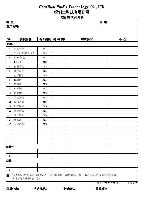
是否测试 测试比率
YES YES YES YES YES YES YES YES YES YES YES YES YES YES YES YES YES YES
特殊要求
பைடு நூலகம்备 注
副板一: 1 2 副板二: 1 2
附:“是否测试栏"请填写YES或者NO”,“测试标准栏”请填写测试比例,“特殊要求栏”请将其它要求或
需增加测试项目请手工追加。 编号:FM-SPZ-0029 版本:A/0
品质作成:
客户承认:
测试确认:
品质核准:
功能测试项目表
机 型: 客户说明: 日 期:
NO. 主板:
1 2 3 4 5 6 7 8 9 10 11 12 13 14 15 16 17 18
测试内容
开机声音 开机电流/待机电流 SIM卡识别 T卡识别 拍照功能 蓝牙激活 蓝牙搜索 FM测试 TV测试 MP3播放 MP4播放 耳机测试 振动测试 回声测试 按键测试 手机通话 传感器 充电功能
测试内容是否测试测试比率特殊要求开机声音yes拍照功能yes蓝牙激活yes蓝牙搜索yesyes10yes11yes12耳机测试yes13振动测试yes14回声测试yes15按键测试yes16手机通话yes17传感器yes18充电功能yes客户说明
ShenZhen YueYu Technology CO.,LTD 深圳xx科技有限公司
