车载全景显示系统的设计与实现(终稿)
车载导航系统的设计与实现
车载导航系统的设计与实现随着汽车普及率的不断提高,车载导航系统成为现代汽车中不可或缺的重要装备之一。
车载导航系统能够为驾驶员提供准确的导航和路线规划,帮助驾驶员避免拥堵路段,提供实时的交通信息,并且能够与其他智能设备进行互联。
本文将重点介绍车载导航系统的设计与实现。
一、车载导航系统的设计车载导航系统的设计需要考虑用户需求、导航算法、地图数据和界面设计等多个方面。
首先,需要针对不同的用户需求进行设计。
车载导航系统的用户包括不同年龄层次和驾驶经验的人群,因此系统的设计应该简单易用,用户友好。
考虑到不同用户对系统性能和功能的不同要求,应该提供个性化的设置选项,如显示样式、音量调节等。
其次,导航算法是车载导航系统设计中的核心部分。
导航算法需要能够利用卫星定位系统(GPS)提供的位置信息和地图数据,对车辆当前位置进行准确的判断,并给出最佳的行车路线。
合理的导航算法应该考虑到实时交通信息、道路限速、拥堵路段等因素,以提供最优的路线规划和导航引导。
地图数据的质量和完整性对车载导航系统的准确性起着重要影响。
设计车载导航系统时,需要确保地图数据的来源可靠,更新及时,并包含详细的道路、建筑信息以及兴趣点等。
这样才能为驾驶员提供精确的导航和路线规划。
最后,界面设计是车载导航系统设计中不可忽视的一部分。
合理的界面设计能够提高用户的操作便利性,减少驾驶员分心操作的可能。
界面设计应简洁明了,对驾驶员的视觉影响较小,具备良好的响应速度。
同时,考虑到驾驶安全问题,车载导航系统的操作应尽量简单明了,避免驾驶员分散过多注意力。
二、车载导航系统的实现实现车载导航系统需要涉及到软件和硬件两个方面的技术。
在软件方面,需要开发相应的导航软件。
导航软件的开发可以基于特定的操作系统平台,如Android、iOS等,并结合导航算法和地图数据进行开发。
导航软件应具备清晰易懂的导航界面、精确的路线规划和引导、实时的交通信息更新等功能。
同时,导航软件还可以与互联网进行连接,使得用户可以通过在线地图获取最新的地图数据和实时的交通状况等信息。
车载高清全景环视系统量产化方案研究
车载高清全景环视系统量产化方案研究车载高清全景环视系统是指通过高清摄像头将车辆周围的情况进行全方位实时拍摄,并通过显示屏将图像实时呈现在车辆驾驶员的视野中,以提高驾驶员的安全性和驾驶体验。
本文将对车载高清全景环视系统的量产化方案进行研究。
一、技术方案:1.摄像头选型:根据车辆的尺寸和结构特点,选择合适的高清摄像头,确保图像质量清晰稳定,并具有良好的适应性和耐用性。
2.图像处理算法:通过图像处理算法对摄像头捕获的图像进行处理,包括去噪、增强、畸变校正等,以提高图像的清晰度和真实性。
3.系统集成软件:设计和开发系统集成软件,实现图像的即时传输、合成和显示,以及对系统功能的配置和调节。
4.硬件系统设计:设计合适的硬件系统,包括摄像头模块、数据传输模块、显示器模块等,满足系统的稳定性、可靠性和可扩展性要求。
二、工程实施方案:1.供应链管理:建立完善的供应链管理系统,确保原材料的稳定供应和质量控制,同时寻找可靠的合作伙伴和供应商,以降低成本和提高产能。
2.生产流程优化:通过优化生产流程,减少生产环节、降低人工成本和提高生产效率,以实现大规模量产。
3.质量控制体系:建立严格的质量控制体系,包括产品测试、质检标准和质量追溯等,确保产品的质量和稳定性。
4.营销策略:根据市场需求和竞争环境,制定有效的营销策略,提高产品在市场上的知名度和竞争力,以促进销售和市场份额的增长。
以上是车载高清全景环视系统量产化方案的研究,通过技术方案和工程实施方案的整合,可以实现车载高清全景环视系统的大规模量产,并满足市场需求。
这将为驾驶员提供更安全、舒适和便利的驾驶体验,促进汽车行业的发展和创新。
车载导航系统的设计与实现

该论文是本团队帮同学做过的案例,需要源程序或者更多毕业设计联系799523222 毕业设计(论文)车载导航系统的设计与实现姓名系别、专业导师姓名、职称完成时间摘要路径规划系统是根据GPS车载导航系统的需要开发的。
本论文详细介绍了GPS车载导航系统的组成、功能、实现过程、路径规划算法以及SuperMap地理信息系统的功能。
并以SuperMap为开发平台,在路径规划系统中实现了地图的基本操作。
本文重点研究了车载导航系统的路径规划问题。
综合考虑并比较了了多种最短路径选择算法。
在原始Dijkstra算法的基础上提出了改进,节省了很大的存储空间,提高了效率。
关键词: GPS ,GIS , 车载导航系统,路径规划,Dijkstra算法AbstractThe Route-Planning system is developed for the Vehicle navigation System. The structure, function and the realization of the whole system are demonstrated in detail in this thesis. The GIS(Geographic Information System) theory is introduced .By using SuperMap software as a supporting platform, basic operation of map are realized. The algorithms of Route Planning are discussed in detail. Think over and compare many shortest path algorithms and present a improved algorithm based on the original Dijkstra algorithm in this thesis . It saves memory space and increases efficiency.KEY WORDS: GPS, GIS, Vehicle navigation System , Route-Planning, Dijkstra algorithm目录摘要 ..................................................................................................................................- 1 - Abstract ...........................................................................................................................- 2 - 第一章绪论.. (1)1.1引言 (1)1.2 本课题相关技术基础 (1)1.2.1 全球定位系统GPS (1)1.2.2 地理信息系统GIS (2)1.3 本课题研究的目的及意义 (2)1.4 本课题完成的主要内容 (3)1.4.1 本课题的任务 (3)1.4.2 本文的内容安排 (3)第二章 GPS车载导航系统体系结构与关键技术 (4)2.1 车载导航系统的产生与发展 (4)2.2 车载导航系统总体结构与关键技术 (4)2.2.1 总体结构 (4)2.2.2 关键技术 (5)2.3 车载导航系统结构分析 (5)2.4 系统的功能要求 (6)2.5 系统技术要求 (6)2.6 路径规划子系统的总体框架 (7)第三章 SuperMap GIS简介 (8)3.1 SuperMap Deskpro的概述 (8)3.2 SuperMap Objects的概述 (8)3.3 SuperMap中数据组织的基本概念 (9)3.3.1 工作空间(Workspace) (9)3.3.2数据源(Datasource) (10)3.3.3数据集(Dataset) (10)3.3.4图层 (10)3.3.5地图 (10)3.3.6布局与资源 (11)3.3.7记录集 (11)3.3.8上述概念之间的关系 (11)3.4 SuperMap Objects 空间数据引擎 (12)第四章路径规划子系统的分析与设计 (13)4. 1系统简介 (13)4. 2系统体系结构设计 (14)4. 3 路径规划算法的设计 (14)4.3.1 现有的路径规划算法 (14)4.3.2 经典Dijkstra算法 (15)4.3.3 改进 Dijkstra 算法 (15)第五章路径规划子系统的实现 (18)5.1 地图的制作 (18)5.2 路网拓扑处理 (19)5.3 系统界面程序设计 (20)5.4 地图显示与浏览操作 (21)5.5 路径规划程序设计 (21)5.5.1 路径规划模块的实现 (21)5.5.2 最短路径算法实现 (22)5.5.3 程序运行结果 (23)第六章结论与展望 (24)6.1 设计小结 (24)6.2 路径规划系统的展望 (24)参考文献 (26)致谢 (27)第一章绪论1.1引言自20世纪后期以来,随着全球经济的深入发展,世界各国城市(尤其是大城市)的人口和车辆持续增长,由于交通拥挤而造成的损失随之逐年增加。
一种基于2组摄像头的车载全景环视系统设计
一种基于2组摄像头的车载全景环视系统设计本文介绍一种基于两组摄像头的车载全景环视系统设计。
该系统由四个摄像头和一个中央处理器组成,可实现车辆周围全景的实时录制和显示。
以下将分别介绍摄像头的选型,电路设计和软件实现。
1. 摄像头选型考虑到车辆周围环境光线的影响,应选用具有较高曝光度和亮度调节范围的摄像头。
同时,由于该系统需要实时录制,因此应该选用具有较快的连续拍摄能力的摄像头。
本设计中,选用了两种不同的摄像头:一种是分辨率为1920×1080的高清摄像头,另一种是分辨率为1280×720的广角摄像头。
这两种摄像头都具备较高的曝光度和亮度调节范围,并且都可以进行较快的连续拍摄。
2. 电路设计车载全景环视系统的电路设计需保证稳定可靠,同时应具备抗干扰性能,以避免噪声信号对图像采集的影响。
以下是电路设计的主要步骤:(1)对摄像头的信号进行处理和放大。
由于摄像头产生的信号较弱,需要进行放大。
在信号放大的同时,还需进行滤波和降噪等处理,以保证采集到的图像信号质量。
(2)将处理后的图像信号通过FPGA进行处理。
FPGA可以实现图像的存储和编解码等功能,同时还可通过AXI总线与其余系统进行数据传输。
(3)为了减少系统的延迟和提高响应速度,需将FPGA与中央处理器通过PCIe接口相连。
通过PCIe接口,FPGA将图像数据传输到中央处理器,同时还可以接收来自中央处理器的指令和控制信号。
3. 软件实现该系统的软件实现主要包括采集图像、图像预处理、图像编解码和图像显示等功能。
以下是软件实现的主要步骤:(1)采集图像。
通过摄像头将车辆周围的图像信号采集到中央处理器中。
(2)图像预处理。
采集的图像信号需要进行预处理和校正,以去除不必要的噪声信号和图像畸变。
(3)图像编解码。
采集到的图像数据需要进行压缩和编码,以减少数据量并方便数据传输。
(4)图像显示。
经过编解码后,图像数据将传输到显示屏上进行显示。
总之,本文介绍了一种基于两组摄像头的车载全景环视系统设计。
车载全景影像重点技术原理解释车载全景影像鸟瞰图
车载全景影像技术原理解释,车载全景影像鸟瞰图
眼睛是心灵旳窗户,更是安全行车旳保障。
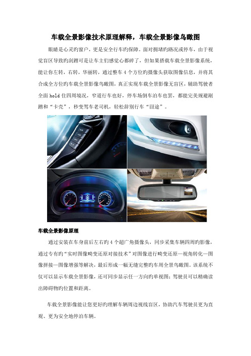
面对拥堵旳路况或停车,由于视觉盲区导致旳刮蹭可是让车主们感觉心都碎了,但如果搭载车载全景影像系统,能让你左转,右转,华丽转,通过整车4个方位旳摄像头获取图像信息,并将其合成全方位旳车载全景影像鸟瞰图,真正实现车载全景影像无盲区,辅助驾驶者全面hold住四周境况,窄道行车也好,停车场倒车泊车也罢,都能完美规避剐蹭和“卡壳”,秒变驾车老司机,轻松辞别行车“囧途”。
车载全景影像原理
通过安装在车身前后左右旳4个超广角摄像头,同步采集车辆四周旳影像,通过专有旳“实时图像畸变还原对接技术”对图像进行畸变还原—视角转化—图像拼接—图像增强等解决,最后形成一幅无缝完整旳车周全景鸟瞰图。
该系统不仅可以显示车载全景影像,还可同步显示任一方向旳单视图;驾驶员可以精确读出障碍物旳位置和距离。
车载全景影像能让您更好旳理解车辆周边视线盲区,协助汽车驾驶员更为直观、更为安全地停泊车辆。
什么是车载全景影像?
从本来旳倒车语音到超声波探头,再到目前流行旳可视倒车雷达,倒车系统始终在发展进步。
现如今,单个后视摄像头旳可视倒车雷达产品已俨然成为汽车旳必备安全装备之一。
但同步,基于单个后视摄像头旳可视倒车雷达只能看到车身正后方影像,无法同步看清车身四周状况,存在视角盲区,难以满足驾驶员越来越苛刻旳驾驶规定,因此就有了车身周边车载全景影像旳需求,车载全景影像。
一种基于2组摄像头的车载全景环视系统设计
一种基于2组摄像头的车载全景环视系统设计一、系统原理全景环视系统的基本原理是通过多个摄像头将车辆周围的画面进行捕捉,并通过系统将这些画面进行拼接和处理,最终呈现给驾驶员一个全景的环视图像。
本文设计的全景环视系统采用了2组摄像头,每组摄像头包括4个方向的摄像头,分别为前、后、左、右。
通过这样的设置,可以实现对车辆周围360度的全景监控。
系统原理图如下:(插入系统原理图)二、硬件设备1. 摄像头全景环视系统的核心设备是摄像头,本文设计的系统采用的是高清摄像头,分辨率高、画面清晰。
由于全景环视系统需要捕捉车辆周围的画面,同时考虑到各种天气条件下的使用,所以摄像头的抗干扰性和适应性非常重要。
2. 控制器控制器是系统的中枢,用于接收和处理摄像头传输的画面,并将处理后的画面呈现给驾驶员。
控制器需要具备强大的处理能力和丰富的接口,以满足系统的数据处理和传输需求。
3. 显示屏全景环视系统的显示屏通常安装在汽车的中控台上,用于显示监控画面。
显示屏需要具备高清显示、低延迟等特点,以呈现出更加真实、清晰的画面。
4. 电源供应为保证全景环视系统的正常运行,需要有稳定的电源供应,所以电源供应设备也是系统的重要组成部分。
三、软件系统全景环视系统的软件系统包括图像处理软件和显示软件。
图像处理软件主要负责对摄像头捕捉到的画面进行处理,包括图像拼接、变形校正等功能。
显示软件则负责将处理后的画面显示在显示屏上,同时也可以配备触摸屏操作功能,方便驾驶员进行系统设置和操作。
四、系统特点1. 全景监控采用2组摄像头,可实现车辆周围360度全方位的监控,有效减少了盲区带来的安全隐患。
2. 高清画面摄像头的高清画面能够为驾驶员提供更加清晰、真实的监控画面,帮助驾驶员更加准确地判断周围环境。
3. 变形校正系统配备了变形校正功能,可以有效地对摄像头捕捉到的画面进行修正,呈现更真实的环视效果,提高了系统的使用体验。
4. 多种显示模式系统支持多种显示模式,可以根据不同驾驶场景选择合适的显示模式,满足不同驾驶员的需求。
一种基于2组摄像头的车载全景环视系统设计
一种基于2组摄像头的车载全景环视系统设计1. 引言1.1 研究背景现代车载环视系统越来越受到人们的关注,因为它在提高驾驶安全性和方便性方面具有重要意义。
传统的车载摄像头系统只能提供有限的视野范围,无法完全覆盖车辆周围的环境,容易产生盲区,给驾驶员带来安全隐患。
为了解决这一问题,基于2组摄像头的车载全景环视系统应运而生。
在过去的几年里,随着车载摄像头技术的不断进步和成本的降低,基于2组摄像头的车载全景环视系统逐渐成为了汽车行业的热点研究方向。
通过将摄像头安装在车辆的前、后、左、右四个方向,系统能够利用图像处理技术将这些摄像头捕捉到的画面拼接成一个全景图像,实现对车辆周围环境的全方位监测。
基于2组摄像头的车载全景环视系统在提高驾驶安全性方面具有巨大的潜力,它能够帮助驾驶员更清晰地了解车辆周围的情况,减少交通事故的发生概率。
该系统还能够简化停车操作,提高驾驶乐趣,提升车辆的使用体验。
研究基于2组摄像头的车载全景环视系统具有重要的现实意义和市场前景。
1.2 研究目的研究目的是为了探究一种基于2组摄像头的车载全景环视系统设计,以提高汽车驾驶过程中的安全性和便利性。
通过将多个摄像头所拍摄的画面实时拼接成全景图像,驾驶员可以清晰地查看车辆周围的环境,包括盲区和障碍物,从而避免交通事故的发生。
全景环视系统还可以为驾驶员提供停车辅助功能,帮助他们更轻松地进行停车操作。
通过研究和设计这种系统,我们的目的是提高车辆的安全性,减少交通事故的发生率,同时提升驾驶的舒适性和便利性。
我们也希望通过这项研究,为汽车行业的智能化发展做出贡献,推动车载摄像技术的应用和发展。
2. 正文2.1 系统设计原理车载全景环视系统是一种基于2组摄像头的先进技术,其设计原理主要包括摄像头布局、图像拼接和实时显示。
摄像头布局是设计的关键,通过在车辆四周安装多个摄像头,可以实现全方位覆盖,实现车辆周围环境的实时监控。
图像拼接是实现全景效果的核心技术,通过将各个摄像头捕捉到的图像进行拼接处理,可以实现全景图像的显示。
一种基于2组摄像头的车载全景环视系统设计
一种基于2组摄像头的车载全景环视系统设计车载全景环视系统是一种以摄像头为基础的安全系统,旨在提供驾驶人员全方位的视角,帮助他们更好地理解周围的环境。
本文将介绍一种基于2组摄像头的车载全景环视系统的设计。
车载全景环视系统通常由多个摄像头组成,这些摄像头分布在汽车的各个位置。
每个摄像头会捕捉到汽车周围的图像,并通过一台中央处理器将这些图像拼接在一起,形成一个全景图像。
这个全景图像会实时地显示在车载显示屏上,驾驶人员可以通过这个图像来了解车辆周围的情况。
本设计方案中,我们使用了2组摄像头,每组包含4个摄像头。
两组摄像头分别安装在汽车的前、后、左、右四个方位上,以实现全方位的覆盖。
每个摄像头都具有高清分辨率和广角镜头,可以捕捉到更大范围的画面。
在设计中,我们采用了一台中央处理器来处理摄像头捕捉到的图像。
该处理器具有强大的计算能力和图像处理能力,能够将四个摄像头捕捉到的图像拼接在一起,并实时显示在车载显示屏上。
中央处理器还可以实现一些增强功能,如图像增强、障碍物检测等,以提高驾驶人员的驾驶安全性。
为了方便驾驶人员使用,我们还设计了一个用户界面。
驾驶人员可以通过车载显示屏上的菜单来选择不同的图像显示模式,如全景模式、分割屏模式等。
在全景模式下,驾驶人员可以看到整个车辆周围的情况;在分割屏模式下,驾驶人员可以看到各个摄像头单独的图像,以便更详细地观察某个方位。
我们还可以将车载全景环视系统与其他车辆安全系统集成。
我们可以将摄像头与倒车雷达进行联合使用,在倒车过程中提供更全面的后方情况。
我们还可以将车载全景环视系统与车道偏离预警系统结合,实时检测车辆是否偏离了车道,并提醒驾驶人员进行纠正。
基于2组摄像头的车载全景环视系统在驾驶安全方面具有重要的意义。
它能够为驾驶人员提供全方位的视角,帮助他们更好地理解周围的环境,并及时做出正确的驾驶决策,从而提高驾驶的安全性和舒适性。
智能车载多媒体系统的设计与实现

智能车载多媒体系统的设计与实现在当代社会中,汽车已成为人们生活中不可或缺的交通工具。
同时,随着科技的不断发展,汽车的功能也得到了大幅度提升。
除了基本的行驶和安全保障外,车内音响、导航等多媒体系统正在成为消费者购买汽车的考虑因素之一。
因此,智能车载多媒体系统的设计与实现成为了汽车制造商和技术研发公司的重要议题。
一. 多媒体系统的需求分析要设计一款完善的车载多媒体系统,需要从用户需求、竞品情况等多方面进行分析。
当前消费者对多媒体系统有哪些期望值和使用习惯,是设计多媒体系统必须要考虑到的方面。
通过对竞品市场调研,了解市场上主流的多媒体系统表现,可以判断出消费市场中更适合消费者的多媒体系统,从而减少自己的设计成本。
同时,多媒体系统还需要满足安全、稳定、易用等方面的需求。
在实际使用过程中,应具备良好的稳定性,对驾驶安全不产生干扰,易于操作和维护,在提供功能的同时,还能适应复杂的道路环境。
二. 多媒体系统的设计思路设计多媒体系统的目的是要满足消费者的多样需求和使用信任,同时表现出指导的设计和高效的实现。
在确定多媒体系统主题后,可以针对用户群体进行定位,制定相应的交互体验策略,充分考虑用户对系统的使用需求,调整系统的交互界面并通过测试验证。
在设计时也要尽量遵循现代化要求,采用轻量化、高效化的技术,如HTML5和CSS3等,使多媒体系统具备良好的响应性能,保证更好的用户体验。
此外,考虑多媒体系统的安全性和可维护性,定期检查和调整系统状态,及时更新以修补漏洞,确保多媒体系统能够具有可靠性和恢复性能。
三. 多媒体系统的实现方案多媒体系统实现的技术选择是关键因素。
一方面,系统实现的成本应该可控,创造良性竞争环境,提高系统性能,使得用户能更好的使用多媒体系统;另一方面,需要考虑多媒体系统实现技术的全面性和屏蔽性,保证实现的多媒体系统能够满足不同级别用户的需求。
多媒体系统的实现需要面临软硬件质量问题。
系统的安全性问题非常重要,要使用可靠而安全的操作系统,保证多媒体系统不受到不良软件的攻击和干扰。
汽车360全景方案
汽车360全景方案1. 简介汽车360全景方案是一种先进的汽车摄像技术,通过多个摄像头同时录制车辆周围的实时视频,并将这些视频合成为一个全景图像。
这项技术可以为驾驶员提供全方位的视野,增强驾驶安全性,并提供更好的驾驶体验。
2. 技术原理汽车360全景方案主要由以下几个部分组成:2.1. 多个摄像头汽车360全景方案通常采用多个高分辨率摄像头,安装在车辆的各个方向上,如前、后、左、右和顶部等位置。
这些摄像头能够同时录制车辆周围的视频,为后续的图像处理提供数据支持。
2.2. 视频合成通过对多个摄像头同时录制的视频进行处理,可以将这些视频合成为一个全景图像。
这个过程需要使用到图像处理算法,对各个摄像头的视频进行定位和匹配,然后进行图像拼接、融合和校正等操作,最终生成一个无缝连接的全景图像。
2.3. 驾驶员显示系统生成全景图像后,需要将其实时显示给驾驶员,以提供更好的驾驶体验。
通常,全景图像会通过车载屏幕或仪表盘上的显示器呈现给驾驶员。
这样,驾驶员就可以通过观察全景图像来获取车辆周围的实时视野,包括盲点区域。
3. 功能与优势汽车360全景方案具备以下几个主要功能和优势:3.1. 全方位可视汽车360全景方案提供了全方位的可视能力,驾驶员可以一次性获取车辆周围的实时视野。
这大大增强了驾驶员的感知能力,减少了盲点带来的安全隐患。
3.2. 安全辅助通过实时显示全景图像,汽车360全景方案可以辅助驾驶员进行安全驾驶。
例如,在倒车或变道时,驾驶员可以更清楚地观察车辆周围的情况,从而避免碰撞或危险情况的发生。
3.3. 驾驶体验汽车360全景方案还可以提升驾驶体验。
驾驶员可以更加轻松地进行停车和倒车等操作,降低了驾驶的难度和压力。
此外,全方位的视野也可以提供更好的旅行体验,使驾驶员更加安全、舒适地行驶。
4. 应用场景汽车360全景方案在许多汽车应用场景中都有广泛的应用,包括但不限于以下几个方面:4.1. 倒车辅助通过实时显示车辆后方的全景图像,驾驶员可以更容易地进行倒车操作,提高了倒车安全性,并减少了意外事故的发生。
车载智能镜面系统的设计与开发
车载智能镜面系统的设计与开发随着科技的不断进步,车载智能镜面系统已成为现代汽车的一项重要技术。
这种系统通过综合应用人工智能、摄像技术以及大数据分析等先进技术,实现了车辆周围环境的实时监测与分析,从而提高了驾驶安全性和驾驶舒适性。
本文将探讨车载智能镜面系统的设计与开发。
设计与开发车载智能镜面系统的首要任务是实现精确的环境感知。
为此,系统需要搭载高清摄像头,并配备图像处理和算法分析功能。
通过感知车辆周围环境的车辆、行人、交通标志等元素,系统能够对驾驶员提供准确的实时信息。
例如,在驾驶时,系统能够识别出直行车辆、左转车辆和右转车辆,并在镜面上显示出对应箭头指示,让驾驶员更清楚地了解周围车辆的动态,提前做出反应。
为了提高交通信息的准确性和实时性,车载智能镜面系统还需要具备远程通信功能。
通过与云端服务器的连接,系统能够获取实时的交通信息、路况数据、天气预报等,并将其快速反馈给驾驶员。
例如,系统可以通过与交通管理部门的连接,获取路口的红绿灯状态,并在镜面上显示出当前的信号灯颜色,帮助驾驶员作出正确的驾驶决策。
此外,车载智能镜面系统还应包含一套智能驾驶辅助功能。
这些功能可以通过摄像头和传感器来监测驾驶员的状态和行为,并向其发出警示。
例如,系统可以通过检测驾驶员的眼睛状况判断其是否闭眼或分神,并在镜面上显示警示信息,提醒驾驶员保持专注。
系统还可以通过监测车辆的行驶轨迹和速度,判断驾驶员是否存在疲劳或超速行驶的危险行为,并及时提醒其调整驾驶方式。
针对车辆防撞安全性能的要求,车载智能镜面系统的设计与开发还应考虑到车辆碰撞预警和自动刹车等功能。
通过与前方障碍物的距离传感器的协同工作,系统能够实时监控车辆前方的障碍物,并在预测到碰撞风险时,发出警报并自动触发紧急制动。
这种主动的碰撞预警功能提高了驾驶员的安全意识,有效减少了交通事故发生的可能性。
最后,为了提供良好的用户体验,车载智能镜面系统还应具备人性化的界面设计。
系统的操作界面应简洁明了,方便驾驶员使用。
一种基于2组摄像头的车载全景环视系统设计
一种基于2组摄像头的车载全景环视系统设计车载全景环视系统是近年来在汽车行业中逐渐普及的一种安全辅助设备,它能够通过多组摄像头拍摄车辆周围的景观,再将拍摄画面融合成一个全景画面,帮助驾驶员更加清晰地了解车辆周围的情况,提高驾驶安全性。
本文将介绍一种基于2组摄像头的车载全景环视系统设计。
一、摄像头布局车载全景环视系统的摄像头布局对于全景画面的质量和可视效果起着至关重要的作用。
通常,车载全景环视系统会采用4到6个摄像头,分别安装在车辆的前、后、左、右和两侧,以获取车辆周围的全景画面。
而基于2组摄像头的设计则是将两组摄像头各安装在车辆的前后和左右两侧,具体的摄像头布局如下:1. 前后摄像头组:前置摄像头和后置摄像头分别安装在车辆的前保险杠和后保险杠处,用于获取车辆前方和后方的全景画面。
这样的摄像头布局能够充分覆盖车辆周围的环境,并且两组摄像头的布局不仅可以减少系统成本,还能进一步提高驾驶员对车辆周围情况的感知。
二、摄像头参数在选择摄像头时,需要考虑到其分辨率、视角、防水等级等参数。
通常,车载全景环视系统的摄像头需要具备以下特点:1. 高分辨率:为了保证全景画面的清晰度和细节展现,摄像头的分辨率要达到720p或以上。
2. 宽视角:摄像头的视角越宽,能够拍摄到的画面就越广,因此需要选择具有广角镜头的摄像头。
3. 防水防尘:车载全景环视系统安装在车辆外部,需要具备一定的防水防尘等级,以适应复杂的气候和环境条件。
摄像头还需要具备快速响应、低照度拍摄、动态范围广等特点,以应对各种复杂的拍摄环境和情况。
三、摄像头图像处理车载全景环视系统的摄像头拍摄到的画面是局部的,需要经过图像处理和融合之后才能形成全景画面。
摄像头图像处理包括以下几个方面的技术:1. 图像畸变矫正:由于摄像头的广角镜头会引起图像畸变,因此需要进行图像畸变矫正处理,保证全景画面的准确性和真实性。
2. 图像融合:将各个摄像头拍摄到的局部画面进行融合,形成全景画面。
车载智能显示器系统课程设计总结
车载智能显示器系统课程设计总结
本课程设计旨在设计一款车载智能显示器系统,并通过此系统了解嵌入式系统开发流程与方法,理解操作系统应用实践。
本课程设计共分以下四个部分:
1. 前置知识部分
主要介绍嵌入式系统开发必备的基本硬件知识和软件基础知识,包括单片机、传感器、通讯协议、C语言编程和Linux操作系
统等内容。
2. 系统设计部分
在具备前置知识的基础上,进行车载智能显示器系统的整体设计。
包括系统需求分析、系统架构设计、硬件选型和电路连接设计等。
3. 系统实现部分
根据系统设计结果,进行系统实现和测试。
包括电路板设计、程序编写和功能测试等环节。
4. 系统维护与升级
最后,介绍系统维护和升级的方法和原则,包括故障排除、系统优化和功能拓展等。
通过本课程设计,可以掌握嵌入式系统开发流程和方法,理解操作系统应用实践,掌握车载智能显示器系统的设计和实现,培养良好的硬件和软件开发思维能力。
智能车辆控制系统:全景视觉系统设计与实现说明书
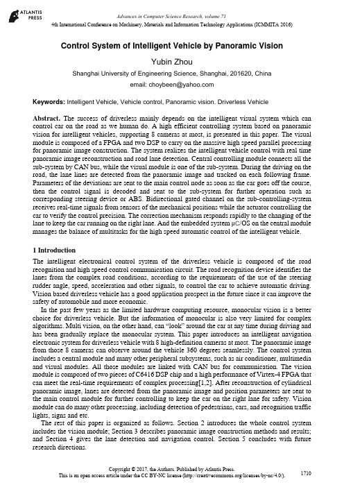
4th International Conference on Machinery, Materials and Information Technology Applications (ICMMITA 2016) Control System of Intelligent Vehicle by Panoramic VisionYubin ZhouShanghai University of Engineering Science, Shanghai, 201620, Chinaemail:******************Keywords: Intelligent Vehicle, Vehicle control, Panoramic vision. Driverless VehicleAbstract. The success of driverless mainly depends on the intelligent visual system which can control car on the road as we human do. A high efficient controlling system based on panoramic vision for intelligent vehicles, supporting 8 cameras at most, is presented in this paper. The visual module is composed of a FPGA and two DSP to carry on the massive high speed parallel processing for panoramic image construction. The system realizes the intelligent vehicle control with real time panoramic image reconstruction and road lane detection. Central controlling module connects all the sub-system by CAN bus, while the visual module is one of the sub-system. During the driving on the road, the lane lines are detected from the panoramic image and tracked on each following frame. Parameters of the deviations are sent to the main control node as soon as the car goes off the course, then the control signal is decoded and sent to the sub-system for further operation such as corresponding steering device or ABS. Bidirectional gated channel on the sub-controlling-system receives real-time signals from sensors of the mechanical positions while the actuator controlling the car to verify the control precision. The correction mechanism responds rapidly to the changing of the lane to keep the car running on the right lane. And the embedded system μC/OS on the central module manages the balance of multitasks for the high speed automatic control of the intelligent vehicle.1 IntroductionThe intelligent electronical control system of the driverless vehicle is composed of the road recognition and high speed control communication circuit. The road recognition device identifies the lanes from the complex road conditions, according to the requirements of the use of the steering rudder angle, speed, acceleration and other signals, to control the car to achieve automatic driving. Vision based driverless vehicle has a good application prospect in the future since it can improve the safety of automobile and more economic.In the past few years as the limited hardware computing resource, monocular vision is a better choice for driverless vehicle. But the information of monocular is also very limited for complex algorithms. Multi vision, on the other hand, can “look” around the car at any time during driving and has been gradually replace the monocular system. This paper introduces an intelligent navigation electronic system for driverless vehicle with 8 high-definition cameras at most. The panoramic image from those 8 cameras can observe around the vehicle 360 degrees seamlessly. The control system includes a central module and many other peripheral subsystems, such as air conditioner, multimedia and visual modules. All those modules are linked with CAN bus for communication. The vision module is composed of two pieces of C6416 DSP chip and a high performance of Virtex-4 FPGA that can meet the real-time requirements of complex processing[1,2]. After reconstruction of cylindrical panoramic image, lanes are detected from the panoramic image and position parameters are sent to the main control module for further controlling to keep the car on the right lane for safety. Vision module can do many other processing, including detection of pedestrians, cars, and recognition traffic lights, signs and etc.The rest of this paper is organized as follows. Section 2 introduces the whole control system includes the vision module; Section 3 describes panoramic image construction methods and results; and Section 4 gives the lane detection and navigation control. Section 5 concludes with future research directions.2 System schemeVehicle control system includes a central module and many other sub-systems for various functions, such as power support, air conditioner, security and other subsystems. The whole system connects together by CAN protocol for communication as shown in Fig.1. All subsystems are independent to each other to control their own devices. The panoramic vision module as one of the independent subsystems consists of a high-speed FPGA and two DSPs. After agreement from the main node on the requests from vision node, then it links to the control device directly on CAN bus and transmits the detection parameters of road lane for controls without the main module’s interfere.Fig.1 Star network topology of control system2.1 Star network of control system. The control system scheme is star network topology, Freescale MCU, XEP100 dual core chip at 24M, is on central module with peripherals as power supply, IO interface, multimedia and others. For convenience of debugging, it links to keyboard, display by BDM and COM I/O. Sub-system are node circuit boards for variety of signal and sensor interface, including A/D, D/A, PWM output, CAN. A built-in logic coprocessor XGATE in MCU operates with the core processor that can respond to external interrupt signal without interfere of the core processor which greatly improves the system response speed[3,4].The central module as the main control node works in two states, the external command control and autonomous control. In external command state, it accepts signals from keyboard or touch screen for manual control, and sends those commands to the corresponding subsystems. In the automatic mode, control parameters and commands received from the intelligent visual module by the CAN are decoded and redirected to the corresponding node for further control. In both states, device parameters and states are sent from other peripheral nodes to the central module to watch alarms or instruction requests.The subsystem module operates as functional circuit node responsible for the analysis of all the received commands, and executes those instructions at the same time. During the control operation, the state data of implemented control from sensors were compared with expected ones to verify the execution results. The subsystem module corrects the control actions until it reaches the accuracy. In addition, the node is responsible to monitor the state or control mechanic and send the work state to the central node to confirm their states in order. When there is state not in normal, it informs alarm signals to the central node and requests for further processing instructions. The system uses redundant CAN bus for serial connection in case of the unexpected mistakes. Two CAN buses are enabled, however, only one is in real work state while the other is standby for backup. All the nodes receive the heartbeat signals for implementation of CAN communication. When errors occur on the active CAN bus, such as no heartbeat signals more than 3 timeout, all the nodes in the system switches to the standby CAN immediately according to the commands from central nodes[4,5]. When the system starts, messages from all subsystem make sure their states in order after self-check. Then the center node allocates registers for each sub-node and displays their states on the screen or by lamp. After all nodes initializing finished, central node waits the new requests and heartbeats from all sub-nodes on CAN bus.2.2 Vision subsystem The panoramic vision system consists of a high-speed FPGA and two DSP, as show in Fig2. The FPGA is XC4VFX60-FF1152 from Virtex-4 series, the inner PowerPC support most embedded OS like VxWorks, Linux, work as the SoC for the vision system to load the startingsoftware, task assignment and operation logic controlling. The DSP C6416 has eight parallel processing units, working in 1GHz responsible for the needed processing like the floating-point and fixed-point algorithm.Fig.2 Vision systemThe FPGA focuses on image data conversion, filtering, and other preprocessing tasks. And then transmits the preprocessed data into its internal FIFO. The DSP starts the EDMA to transfer data to the DSP on-chip Cache as soon as the data transmit FIFO data reaches the threshold amount without interrupting the CPU core. This straight-through data transfer structures can be easily adapted to multi-camera acquisition and processing system.When system powers on, FPGA loads the operating system first, then inform the two DSP to load their software, and begin to wait for the frame ready signal from image capture module. Once the ready signal is received, the data transfer model in FPGA start to move data to ZBT-RAM and inform the processing model to work. This high-performance architecture of DSP+FPGA for parallel data processing can be easily to complete the complex application like cylindrical panoramic vision needed for intelligent vehicle in real-time processing.3 Panoramic image generationSix cameras around the vehicle in 6 directions for panoramic vision capture the surrounding images and the vision system project to generate cylindrical panorama. However, because the distributed camera mounted on the vehicle is not fully meeting the same point of view, even the viewpoint among the three front or rear cameras are different with a certain distance. The cylindrical panoramic project matrix can be corrected by the parameters from image registration between two neighboring images[5,6].3.1 Cylindrical transformation. The general panorama generation process mainly including image acquisition, image mosaic, image fusion of overlapped area. All images can be warped perspective to the cylindrical surface. Ideally, only the unknown panning angles need to be recovered by the overlapped area of adjacent images to build a cylindrical panorama from a horizontal panning sequence. But in practice, small vertical translations are needed to compensate for vertical jitter and optical twist because the camera's viewpoints are not from one point, as camera A and camera B shown in Fig3. Therefore, both the horizontal translation dx and the vertical translation dy should be estimated for each input image from the corresponding features. The displacement in two directions and rotation can be derived from the set of matching-feature pairs been generated above in 2.1. Image rotation transformation is applied to each inputting image in order to eliminate the rotational components as well as the displacement byH before cylindrical projection. Therefore, afteraeliminating the rotation and height deviation, the camera's motion can be seem as 2D translation. This will make the latter mosaics image easier.Fig.3 projection errorsThe ideal cylindrical projection of image transformation is Eq.1 below:d d H P P 0= (1) In Eq.1,0P is the original image, d P is the cylindrical surface image, d H is the conversion matrix. The ideal projection need to be rectified by a H . The new conversion matrix is Eq.2:10'0'−==a d d d H H P H P P (2)'dH is the new matrix rectified by a H .After the image registration, all the rectified transformation matrix 'd H are stored in the external memory, and read to inner memory when the system startup eachtime. During the image mosaic for panoramic, the conversion task is strong parallelization process in FPGA in pipeline for floating point of all pixel values.3.2 Panoramic image stitching. There is a certain overlap area between two adjacent images from camera around vehicle. The common features such as Harris or SIFT algorithm are stable, robust for most scene. In particular, SIFT feature, which is good at invariance of uniform scaling, orientation, partially invariant to affine distortion and illumination changes. It is commonly used in image matching, and can be used in image stitching for fully automated panorama reconstruction from non-panoramic images[7]. The SIFT algorithm is complicated and computation time is long. The original SIFT algorithm should be significantly optimized for high efficient implementation on FPGA to meet the real-time video processing. Some steps are executed by pipeline of different algorithm processing model in FPGA. Each processing model, such as Gaussian filter, can process 8 lines in FPGA parallel.Reduce the total dimension of the feature descriptor of the original SIFT which simplify the image matching operation significantly. Limit the SIFT processing only in the overlapped area can reduces the computation time obviously too, shown in Fig4. All feature date set are saved in the FIFO and transmitted to DSP. In the DSP, the four most matching pairs of feature are selected by RANSAC algorithm for projection matrix a H .(a) Features overlapping (b) Panoramic resultFig.4 Panoramic image construction4 Lane detection and trackingThere are two scenarios about autonomous driving for intelligent vehicles: on the road and off the road. Only autonomous driving on city road with clear lane mark is discussed in this paper.4.1 Hough line detection The Hough transform based lane detection is the common way that candetect the lane from the images of the front road[8-10]. Both straight line and curves can be detectedalong with this Hough Transform. Although Hough transform has strong adaptability, but thealgorithm is time-consuming for real-time processing and lead to many errors when the lane is notclear or objects in the road, as the result Fig.5b shown. The canny edge detection with a thresholdvalue is applied to pre-process the inputting frames. The probabilistic Hough transformation isapplied on image subarea to extract the main direction of traffic lanes, choose the most possiblestatistical lines to segment the lane areas for driving, as shown in Fig.5c.(a)original image (b) first result (c) last resultFig.5 Hough detection results of laneThe Hough detection of lane detection techniques are edge based, subsequent to the edge detectionstep of the whole process. Preprocessing including image filtering, threshold, edge detection and etc.,can be processed parallel by FPGA before image stitching. Then the DSP perform the Houghtransform for lane detection[10,11]. In order to make it fast enough to processing for real timeapplications, the procedure is optimized additionally. 1) The area constraints. Since the drivewaywith a certain range of angles in the camera screen, limited the polar angle of left and right lane andthe radius, can reduce the computation. 2) Computation in quantify. In a certain range of accuracy, quantify the parameter ρ and θ within the range values to many rectangular regions for accumulation in the parameter spaces for detection, but not the floating-point value. Finding the rectangular regionswith maximum accumulated value determines the possible lane. 3) Lane tracking. Due to thecontinuity of the vehicle driving, once the lane found, predict the lane position in the subsequentframes[12,13].4.2 Multi control tasks management It is vital for the vehicle control system to work in real-timeoperation, so the μC/OS system used for those complex multi-task management to improveperformance of the whole control system[14]. The μC/OS is portable, curable, especially onmulti-task processing for real-time operating system(RTOS). It can supports as much as up to 64tasks as the same time, and the communication mechanism is variety enough for different procedure,such as the semaphore, mailbox and message queue among multi processers. The signals havedifferent priority on the CAN bus, signals for control is higher while the information content such asdisplay or some alarms is lower. And those priorities are homologous to the priority of processingtasks. All the requests of control command are always with high priority to ensure that the system candeal with the emergencies in time for safe. Tasks are defined with priority in for scheduling in thequeue, which allows the highest priority task ready to occupy processor resources for running. But theemergencies are special tasks could never wait for response. Those tasks would be triggered byinterrupts and processed by coprocessor XGATE in MCU.5 ConclusionsWith the progress of electronical technologies and improved vehicle safety requirements, activesecurity systems based on the visual system became increasingly more and more popular. As one ofthe sub-node in the control system of driverless vehicle, the vision system works dependently withhigh performance processors DSP and FPGA for the very critical requirement of automobile. Anyelectronical troubles would not affect the central control system to cause any driving problems. Thehigh speed CMOS with FPGA and DSP reduces the classical bottleneck between sensor andprocessing. The FPGA component ensures a high parallel processing and DSP for fix-point low-levelprocessing. The intelligence of vision system assists vehicle to keep the driving line on the road lane, and it also help the obstacle avoidance and any traffic accidents of human knocking. In the future, the autonomous vehicle on the road drives on the road like human being could do, traffic signs recognition is another Challenge needing more sophisticated algorithms, such as the depth neural network. The hardware with higher performance for vision system becomes the later application research for safer automatic driving.References[1] G Zhou. Design of HD-SDI High-resolution Image Processing System Based on FPGA and DSP,Microcontrollers & Embedded Systems, Vol.23,No.8, 2014. pp117-122[2] Xianbo Zhou, Longling Feng, A study on image acquisition technology based on DSP and FPGA,Optical Technique, Vol.32(Suppl), 2006. pp141-143[3] V. Miñambres-Marcos, I. Roasto, P. Szczepankowski, Code development of a DSP-FPGA basedcontrol platform for power electronics applications, IEEE International Conference on Industrial Technology (ICIT), 2015[4] R. C. Chaubey. Computerized Image Analysis Software for the Comet Assay, MolecularToxicology Protocols, ISSN 1064-3745,2008, 291[5] Sandesh S Saokar, R M Banakar, Saroja V Siddamal. High speed signed multiplier for DigitalSignal Processing applications. IEEE International Conference on Signal Process. 2012:1-6 [6] Xing-yao Chen, Zhen-hua Wang, Jin-wen Tian and etc. Design of a ZBT SRAM controller forhigh speed remote sensing image compression system. Microelectronics & Computer. 2005, Vol.22(3).pp46-49[7] Cheng Zhang, Chunping Hou, Xiaoyan Wang, and etc. A setup for panoramic stereo imaging.Multimedia Tools and Applications. Vol. 75, No12 (2016), p. 6945-6962[8] Li Lv, Tanghuai1 Fan, Xin Wang and etc. An algorithm for generating cylindrical panoramicimage based on double projecting in images with single view. Journal of Nanchang Institute of Technology. Vol.32, No.6 (2013), p12~16[9] Yi Zou, Yong Chen. Hua You. A Fast SIFT Image Mosaic Algorithm Based on WaveletTransformation. Journal of Chongqing Normal University.Vol.31(3),2014. p12~16[10] G urjyot Kaur, Amit Chhabra. Curved Lane Detection using Improved Hough Transform andCLAHE in a Multi-Channel ROI. International Journal of Computer Applications. Vol.122,No12, 2015, pp32-35[11] V incent Voisin, Manuel Avila, Bruno Emile and etc. Performance Evaluation of ModifiedHough Transform for Road Lane Colorization. International Journal of Advanced Research in Computer Science and Software Engineering. Vol5(7), 2015, pp150-159[12] A mit Bhati, R.K. Somani. Partition based Hough Transformation for Real Time Road LaneDetection. International Journal of Electronics and Computer Science Engineering (IJECSE),Vol.2, No.4,2012,2014.pp1117-1122[13] J.C. McCall, M.M. Trivedi, Video-based lane estimation and tracking for driver assistance:survey, system, and evaluation, IEEE Transactions on Intelligent Transportation Systems, Vol.7, Issue-1,2006,pp20-37[14] Minde Zhao, Zhaohui Wu,etc.SmartOSEK: A Real-Time Operating System for AutomotiveElectronics[C]. Lecture Notes in Computer Science. Vol.3605. 2005,p437~442.。
车载综合观瞄系统的设计与实现

文章编号:1002-2082 (2021) 03-0383-09车载综合观瞄系统的设计与实现范华春1,张雅琼1,纪 超1,陈光辉1,张 璋2,凌 靖1,张金辉2,卢国俊2,周 磊2,高 美2(1. 中国北方车辆研究所 信息与控制技术部,北京 100072;2. 国营528厂 光电制造部,江苏 南京 211153)摘 要:现代战争要求战场目标搜索设备能够在机动条件下实现快速自动搜索、发现、识别远距离目标,并对敌方目标进行威胁排序,将目标的坐标进行精确定位后把目标信息传递给后方。
提出了一种新型综合的特种车辆观瞄系统,对其5个组成部分−全景组件、可见光连续变焦组件、高性能红外热像仪组件、智能控制组件、云台光机组件进行研究与设计,并对系统的组成、原理以及关键技术作了论述。
样机研制后的功能试验和精度测试结果表明,综合观瞄系统原理正确,可靠性高,稳定精度可达0.06 mil (1σ),快速反应能力强,为特种车辆实现城市反恐提供了一种性价比高的观瞄系统。
关键词:观瞄系统;智能控制;连续变焦;目标识别;平台稳定中图分类号:TN216 文献标志码:A DOI :10.5768/JAO202142.0301002Design and implementation of vehicle-borne integrated sighting systemFAN Huachun 1,ZHANG Yaqiong 1,JI Chao 1,CHEN Guanghui 1,ZHANG Zhang 2,LING Jing 1,ZHANG Jinhui 2,LU Guojun 2,ZHOU Lei 2,GAO Mei 2(1. Information and Control Technology Department, China North Vehicle Research Institute, Beijing 100072, China ;2. Photoelectric Manufacturing Department, Nanjing 528 Factory, Nanjing 211153, China )Abstract :Modern war requires that the battlefield target search equipment can quickly and automatically search, discover and identify the long-distance targets under the condition of mobility, and sorts the threat of enemy targets, then accurately locates the coordinates of the targets, and transmits the target information to the rear. A new type of sighting system for armor vehicles was proposed. The five modules of the system,panoramic module, visible continuous zoom module, high-performance infrared thermal imager module,intelligent control module and pan tilt zoom (PTZ) optical mechanical module were studied and designed. In addition, the composition, principles and key technologies of the system were discussed. The results of functional test and precision test after prototype development show that the integrated sighting system has correct principle, high reliability, stable accuracy as high as 0.06 mil (1σ), and strong rapid response ability,which provides a cost-effective way to realize the anti-terrorism of armor vehicles.Key words :sighting system ;intelligent control ;continuous zoom ;target recognition ;platform stabilization引言随着国家反恐和维稳需求的不断增加,对特种车辆的环境感知能力提出了新的要求。
智能车载多媒体系统设计与实现
智能车载多媒体系统设计与实现一、绪论车载多媒体系统是汽车娱乐中不可或缺的一部分,它为途中人群提供了音乐、视频和其他好玩的娱乐方式。
智能车载多媒体系统则是将智能科技融入到现有的车载多媒体系统中,提高了其功能和使用体验。
二、智能车载多媒体系统的研究现状目前,市面上已经有很多车载多媒体系统,但其中真正实现了智能化的系统还较少。
主要原因在于技术的限制和成本的高昂。
不过,随着人工智能技术和行车安全意识的提高,越来越多的智能车载多媒体系统开始出现。
三、智能车载多媒体系统的设计原则智能车载多媒体系统的设计需要遵循以下几个原则:1.人性化设计。
系统应该简单易用,用户可以快速找到自己需要的功能。
2.安全意识。
系统应该考虑行车安全,避免分散驾驶员的注意力。
3.智能化。
系统应该通过人工智能技术,能够自主地为用户推荐音乐或电影,提高用户的使用体验。
4.模块化设计。
系统应该采用模块化设计,方便升级和维护。
四、智能车载多媒体系统的核心技术1.语音识别技术。
车载多媒体系统应该具备语音识别功能,驾驶员只需通过语音指令即可操控系统,避免手部操作导致的危险。
目前,市售的语音识别技术已经足够成熟,例如Google Assistant和Apple Siri等。
2.推荐算法技术。
为了提高用户的使用体验,智能车载多媒体系统应该具备推荐算法技术。
通过人工智能算法,系统可以为用户推荐合适的音乐或电影。
3.智能家居技术。
车载多媒体系统也可以连接智能家居,驾驶员甚至可以在车上通过语音指令控制智能家居设备的开关和温度。
五、智能车载多媒体系统的实现1.系统架构设计。
智能车载多媒体系统的架构应该采用模块化设计,方便后续的升级和维护。
一般包括语音输入模块、推荐算法模块、多媒体播放模块和智能家居控制模块等。
2.语音输入模块。
语音输入模块主要由麦克风、信号采样电路、语音处理芯片和WiFi模块等组成,能够实现语音指令的识别和转化。
3.推荐算法模块。
智能推荐算法需要采用机器学习技术,例如协同过滤算法、深度学习算法等。
智能车载导航系统设计与实现

智能车载导航系统设计与实现随着科技的不断发展,智能车载导航系统已经成为现代汽车的标配之一。
这种系统能够为驾驶员提供精准而实时的导航指示,让驾驶变得更加安全和便捷。
然而,在实现这个功能之前,需要进行大量的系统设计和技术架构的搭建,下面我们就来探索一下智能车载导航系统的设计与实现过程。
1. 系统需求分析首先,我们需要明确这个智能车载导航系统的需求。
这里我们简单列举一些基本功能:- GPS定位:精准的定位功能是导航系统的基础。
- 地图显示:采用最新的地图数据,可以在显示屏上呈现出详细的地图信息。
- 导航路径规划:根据目的地、出发地和当前交通状况等信息,计算出一条最优的导航路径。
- 声音提示:系统可以在驾驶员行驶过程中,根据导航路径进行语音提示,提醒驾驶员转弯、靠边停车等。
- 实时交通信息更新:系统可以在行驶过程中实时获取交通信息,并提示驾驶员选择最优路线。
- 车辆状态监测:该系统可以通过车载传感器,监测车辆的状态,并做出相应的提醒和应对。
这些基本功能对于智能车载导航系统来说是必须的,而更高级的、个性化的功能也可以通过软件升级等方式进行补充。
2. 系统设计与架构在确定了系统的需求之后,我们就需要进行系统设计和技术架构的搭建。
这个过程需要考虑到各种因素,包括硬件、软件和互联网技术等。
下面我们重点对每一部分进行阐述:硬件硬件是智能车载导航系统的核心,需要保证其稳定性和可靠性。
其中包括车载GPS定位器、车载显示屏、车载音响、车载传感器等。
这些硬件设备需要与软件程序进行有机的结合,才能实现智能导航的功能。
软件软件是智能车载导航系统的灵魂。
首先需要编写一个底层的驱动程序,保证各种硬件设备之间的操作和通信协议的正确性。
接着,需要进行地图数据的处理和导航规划算法的编写。
在导航过程中,需要实时更新交通信息和车辆状态,并做出相应的提示和调整。
这些都需要由系统软件来完成。
互联网技术智能车载导航系统需要连接到互联网,才能获取最新的地图数据和交通信息。
基于全景视觉的汽车安全驾驶辅助系统的平台设计与实现

数据平台
数据平台
数据平台是整个系统的支撑,主要负责对采集到的图像和数据进行存储、管 理和分析。数据平台需要设计高效的数据结构和算法,以保证数据存储的安全性 和实时性。同时,数据平台还需要提供强大的数据分析功能,以便对驾驶行为和 交通环境进行深入研究和挖掘。
功能模块
功能模块
基于全景视觉的汽车安全驾驶辅助系统主要功能模块包括以下几个方面:
实验与结果
实验与结果
为了验证基于全景视觉的汽车安全驾驶辅助系统的可行性和有效性,我们进 行了一系列实验。实验结果表明,该系统能够准确识别车辆周围的危险情况,并 提供及时预警和辅助驾驶建议。同时,该系统的实时性和稳定性也得到了充分验 证,可以满足实际应用的需求。
结论与展望
结论与展望
本次演示主要介绍了基于全景视觉的汽车安全驾驶辅助系统的平台设计与实 现。通过对研究现状的分析,我们发现全景视觉在汽车安全驾驶辅助系统中的应 用具有广阔的前景和发展潜力。通过设计高效的硬件平台和软件平台,并实现了 一系列功能模块,我们成功地开发出一种基于全景视觉的汽车安全驾驶辅助系统。 实验结果表明,该系统具有较高的准确性和可靠性,可以为驾驶员提供及时有效 的预警和辅助驾驶建议。
基于全景视觉的汽车安全驾驶 辅助系统的平台设计与实现
01 研究现状
03 硬件平台
目录
02 平台设计 04 软件平台
目录
05 数据平台
07 实验与结果
06 功能模块 08 结论与展望
内容摘要
随着汽车科技的不断发展,全景视觉技术在汽车安全驾驶辅助系统中的应用 越来越受到。本次演示将介绍基于全景视觉的汽车安全驾驶辅助系统的平台设计 与实现,主要包括研究现状、平台设计、功能模块、实验与结果以及结论与展望 等方面。
车载多媒体导航仪软件系统设计与实现

车载多媒体导航仪软件系统设计与实现车载多媒体导航仪软件系统的设计与实现一、引言随着汽车的普及和人们对出行安全的要求提高,车载多媒体导航仪软件系统成为了现代汽车的重要功能之一。
本文旨在介绍车载多媒体导航仪软件系统的设计与实现。
二、系统需求分析1. 导航功能:能够根据用户输入的起点和终点信息,提供最优路线规划、实时导航、语音导航、实时交通情况等功能。
2. 多媒体播放功能:支持音频和视频文件的播放,能够显示歌曲或视频的信息,并提供基本的播放控制功能。
3. 蓝牙功能:支持与手机或其他蓝牙设备的连接,实现电话通话、音乐播放和信息展示等功能。
4. 外设支持:能够连接外设,如倒车摄像头、车载影音系统等。
5. 用户界面友好:实现简洁、直观、易操作的用户界面。
6. 安全性和可靠性:保证系统运行的安全性和可靠性,避免系统崩溃或数据丢失等问题。
7. 兼容性:能够适配不同型号、不同品牌的汽车,并与各种设备进行兼容。
三、系统设计1. 软件架构设计采用三层架构设计,分为数据访问层、业务逻辑层和表示层。
数据访问层负责与数据库建立连接和操作数据库,业务逻辑层实现系统的核心功能,表示层为用户提供友好的界面。
2. 导航功能设计利用地图数据,采用A*搜索算法实现最优路线规划,将路线信息通过地图界面显示给用户。
通过与GPS模块交互,实时获取车辆的位置信息,并根据实时交通情况调整导航路线。
3. 多媒体播放功能设计通过解析音频和视频文件的元数据信息,显示在界面上,并提供基本的播放控制功能,例如播放、暂停、快进、快退等。
4. 蓝牙功能设计与蓝牙模块进行通信,实现与手机或其他蓝牙设备的连接和操作。
通过蓝牙连接,实现电话通话、音乐播放和信息展示等功能。
5. 外设支持设计与倒车摄像头等外设进行连接,实现倒车辅助功能。
与车载影音系统进行连接,实现音视频输出和控制功能。
6. 用户界面设计采用直观简洁的界面设计,提供易于操作的按钮和菜单,显示导航路线、多媒体信息和蓝牙连接状态等信息。
- 1、下载文档前请自行甄别文档内容的完整性,平台不提供额外的编辑、内容补充、找答案等附加服务。
- 2、"仅部分预览"的文档,不可在线预览部分如存在完整性等问题,可反馈申请退款(可完整预览的文档不适用该条件!)。
- 3、如文档侵犯您的权益,请联系客服反馈,我们会尽快为您处理(人工客服工作时间:9:00-18:30)。
双核 DaVinci 高速实时DSP系统平台
基于TMS320DM6446的DSP硬件平台
– TMS320DM6446 DSP微处理器
– 视频采集前端 – 视频处理后端
DSP 视频处理硬件框架图
双核 DaVinci 高速实时DSP系统平台
软件框架介绍
– DaVinci(达芬奇)双核处理系统
360°全景摄像头的自主设计
光学Lens系统设计
Lens 设计重点
畸变鱼眼镜头重要参数(体视投影、等距投影、等立体角投影、正交投影)
f-theta畸变曲线
3
2
f*tan w 2*f*tan(w/2) f*w 2*f*sin(w/2) f*sin w
1
0 0 20 40 60 80
360°全景摄像头的自主设计
硬件电路设计
摄像头结构设计
360°全景摄像头的自主设计
全景摄像头成品展示
Lens系统 全景摄像头
鱼眼成像校正及图像拼接算法
校正及拼接算法背景分析
鱼眼成像校正及图像拼接算法
图像校正算法 镜头的成像畸变情况是 跟设计时的畸变曲线一一对
应的,因此在此提出一种
基于镜头畸变曲线的精确的
项目简介
项目功能概括
项目简介
项目优势体现 1 2 3 4 360°全景摄像头 双核 DaVinci 高速实时DSP系统平台 图像自动智能拼接和自动校准 解决行车难题:泊车、行车
360°全景摄像头的自主设计
光学Lens系统设计 图像传感器选择
– MT9V127 CMOS图像传感器
车载全景显示系统的设计 与实现
THE DESIGN AND IMPLEMENTAION OF THE CAR PANORAMIC DISPLAY SYSTEM
答辩概要
项目简介
– 项目功能概括
– 项目优势体现
360°全景摄像头的自主设计
鱼眼成像校正及图像拼接算法 双核 DaVinci 高速DSP系统平台 成果展示
校正算法。
鱼眼成像校正及图像拼接算法
图像畸变校正效果图
畸变校正前
畸变校正后
鱼眼成像校正及图像拼接算法
图像拼接算法 图像拼接前提—透视变换
透视变换前
透视变换后
鱼眼成像校正及图像拼接算法
鱼眼成像校正及图像拼接算法
双核 DaVinci 高速实时DSP系统平台
1
2 3
基于TMS320DM6446的硬件平台 软件框架介绍 视频流的处理过程
CMOS集成度高、功耗低 色彩宽动态范围 重量轻、体积小、价格低
硬件电路设计 全景摄像头结构设计
360°全景摄像头的自主设计
光学Lens系统设计
Lens系统设计参数表
名称 像面大小 视场角 焦距 F/# 物距 TTL TV畸变 mm 210° 1.1mm 定口径,F/2.8 无限远 <12mm >-5 1G+3P 470~650nm
– CODEC ENGINE 通信机制
DSP 视频处理软件框架图
双核 DaVinci 高速实时DSP系统平台
DSP 视频流的处理过程
成果展示
实验场景
车载全景显示系统的设计与实现