SI4900DY中文资料
VJ3040Y224KXGAT8R;VJ3640Y334KXGAT8R;VJ4044Y564KXGAT8R;中文规格书,Datasheet资料

TERMINATION (P) MINIMUM 0.010 [0.25] 0.010 [0.25] 0.020 [0.50] MAXIMUM 0.030 [0.76] 0.030 [0.76] 0.040 [1.00]
3040 3640 4044
Document Number: 45203 2 For technical questions, contact: mlcc@ THIS DOCUMENT IS SUBJECT TO CHANGE WITHOUT NOTICE. THE PRODUCTS DESCRIBED HEREIN AND THIS DOCUMENT ARE SUBJECT TO SPECIFIC DISCLAIMERS, SET FORTH AT /doc?91000 /
FEATURES
• Integrated resistor on the surface of the capacitor • Low electrostrictive ceramic formulation for repeated charge and discharge cycles • High pulse discharge currents • Excellent reliability and high voltage performance • Available with tin/lead barrier termination (code “L”) • Wet built process • Reliable Noble Metal Electrode (NME) system • Made with a combination of design, materials and tight process control to achieve very high field reliability • Resistor glass overglaze contains lead • Material categorization: For definitions please see /doc?99912
SI9801DY中文资料

20
ID – Drain Current (A)
VDS – Drain-to-Source Voltage (V)
Gate Charge
4.5 4.0 V GS – Gate-to-Source Voltage (V) r DS(on)– On-Resistance ( W ) (Normalized) 3.5 3.0 2.5 2.0 1.5 1.0 0.5 0 0 1 2 3 4 5 6 0 –50 VDS = 3.5 V ID = 0.8 A 1.6 2.0
5-4
Document Number: 70712 S-61825—Rev. C, 16-Aug-99
Gate-Source Charge
Qgs
Gate-Drain Charge
Qgd
Rise Time
tr
Turn-Off Delay Time
td(off)
trr
Notes a. Pulse test; pulse width v 300 ms, duty cycle v 2%. b. Guaranteed by design, not subject to production testing.
Output Characteristics
20 VGS = 5, 4.5 thru 3 V 16 I D – Drain Current (A) I D – Drain Current (A) 16 20 TC = –55_C 25_C
N CHANNEL
Transfer Characteristics
Gate Threshold Voltage VGS(th) VDS = VGS, ID = 250 mA VDS = VGS, ID = –250 mA VDS = 0 V, VGS = "12 V VDS = 20 V, VGS = 0 V Zero Gate Voltage Drain Current Z G V l D i C IDSS VDS = –20 V, VGS = 0 V VDS = 20 V, VGS = 0 V, TJ = 70_C VDS = –20 V, VGS = 0 V, TJ = 70_C On-State Drain Currenta ID(on) VDS = 5 V, VGS = 4.5 V VDS = –5 V, VGS = –4.5 V VGS = 4.5 V, ID = 4.5 A D i S O S R i Drain-Source On-State Resistancea rDS(on) VGS = –4.5 V, ID = –4.0 A VGS = 3.0 V, ID = 3.8 A VGS = –3.0 V, ID = –3.0 A Forward Transconductancea gfs VDS = 15 V, ID = 4.5 A VDS = –15 V, ID = –4.0 A IS = 1.7 A, VGS = 0 V IS = –1.7 A, VGS = 0 V N-Ch P-Ch N-Ch P-Ch N-Ch P-Ch N-Ch P-Ch N-Ch P-Ch N-Ch P-Ch N-Ch P-Ch N-Ch P-Ch N-Ch P-Ch 20 A –20 0.044 0.064 0.055 0.086 11.5 S 9.8 0.73 –0.75 1.2 V –1.2 0.055 0.080 0.075 0.120 W 0.6 V –0.6 "100 "100 1 –1 25 –25 mA A nA
编俄罗斯电子器件对照手册
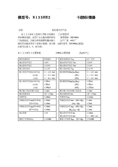
俄型号:К133ИЕ2十进制计数器说明相应国内外产品К133ИЕ2型单片TTL中规模半□中国型号导体集成电路,由四个主从触发器和附加推荐替换SG5490A门电路组成,功能为具有清零和置9输入生产厂家4435厂端的负沿触发异步十进制计数器。
其计数□国外型号SN5490A (美国)长度可以是2、5、10分频。
К133ИЕ2主要参数5490A主要参数(T A=25℃)К133ИЕ2逻辑图和外引线排列5490A功能表和外引线排列俄型号:К133ИЕ54位二进制计数器说明相应国内外产品К133ИЕ5型单片TTL中规模半□中国型号导体集成电路,由四个主从触发器和附加推荐替换SG5493A门电路组成。
可组成二分频计数器和三级生产厂家4435厂二进制计数器,具有清零输入端。
□国外型号SN5493A (美国)К133И5主要参数5493A主要参数(T额定电源电压5V±10%额定电源电压V CC 4.5~5.5V 输出低电平电压≤0.35V输出低电平电压V OL≤0.4V输出高电平电压≥2.4V输出高电平电压V OH≥2.4V输入低电平电流(2,3)(1,14)≤|-1.6|mA≤|-3.2|mA输入低电平电流I IL (R0(I))(CP1,CP2)≤|-1.6|mA≤|-3.2|mA输入高电平电流(2,3)(1,14)≤40μA≤80μA输入高电平电流I IH (R0(I))(CP1,CP2)≤40μA≤80μA输出短路电流I OS-20~-57mA电源电流≤46mA电源电流I CC≤39mA传输延迟时间t PLH( 14→11)(2,3→12)≤135ns≤100ns传输延迟时间t PLH (CP1→Q3)≤70ns传输延迟时间t PHL (14→11)≤135ns传输延迟时间t PHL (CP1→Q3)≤70ns扇出系数≤10输出低电平电流I OL输出高电平电流I OH ≤16mA≤|-800|μA最高工作频率(C1)≤15MHz最高工作频率f max (CP1→Q0)(CP2→Q1)≥32MHz≥16MHz时钟输入脉冲宽度(C1)预置输入脉冲宽度≥50ns≥50ns输入脉冲宽度t W (CP2)(CP1, R0(I))≥30ns≥15nsК133ИЕ5逻辑图和外引线排列5493A功能表和外引线排列俄型号:К133ЛА28输入与非门说明相应国内外产品К133ЛА2型单片TTL小规模半□中国型号导体集成电路,功能为8输入端与非门。
SI4480DY中文资料
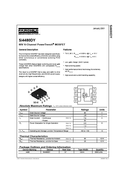
VDD = 40 V, ID = 1 A, VGS = 10 V, RGEN = 6 Ω
13 8 34 16
26 20 60 30 46
ns ns ns ns nC nC nC
VDS = 40 V, ID = 7.6 A, VGS = 10 V
34 6.1 6.9
Drain-Source Diode Characteristics and Maximum Ratings
Off Characteristics
BVDSS ∆BVDSS ∆ TJ IDSS IGSSF IGSSR Drain-Source Breakdown Voltage Breakdown Voltage Temperature Coefficient Zero Gate Voltage Drain Current Gate-Body Leakage, Forward Gate-Body Leakage, Reverse
2 RDS(ON), NORMALIZED DRAIN-SOURCE ON-RESISTANCE 1.8 1.6 1.4 1.2 1 0.8 0.6 0.4 -50 -25 0 25 50 75 100
o
ID = 7.6A VGS = 10V
ID = 3.8A 0.05 TA = 125oC 0.04 0.03 0.02 0.01 0
Scale 1 : 1 on letter size paper 2: Pulse Test: Pulse Width ≤ 300 µs, Duty Cycle ≤ 2.0%
Si4480DY Rev A
元器件交易网
FDS3580 Si4 480DY
Typical Characteristics
德克萨斯工业设备 1 4 英寸空气角 电镀机用户手册说明书

7.With a firm grip on the Die Grinder, lightly apply the Grinding drum to the workpiece, slowly and steadily moving the grinding drum to the right and left until you have achieved the desired appearance (finish) on the workpiece. 8.Once the work is completed, release hand pressure on the trigger, the safety will automatically return to its locked position to prevent the trigger from accidentally being activated. 9.Turn off the air compressor. Trip the safety with your finger, and slowly squeeze the trigger to release any remaining air pressure from the die grinder. Then disconnect the air hose from the tool. 10.Remove the grinding drum from the Die Grinder. Then store the tool in a clean, dry location out of reach of children and untrained operators.
GENERAL SAFETY RULES
芯片容量识别
* K9x1Gxxxxx = 1Gb (GigaBit) = 128MB (MegaByte)
* K9x2Gxxxxx = 2Gb (GigaBit) = 256MB (MegaByte)
* K9x4Gxxxxx = 4Gb (GigaBit) = 512MB (MegaByte)
K9F1G08U0M-VIB0 128MB
K9F1G08U0M-FIB0 128MB
K9K2G08U0M-YCB0 256MB
量 128MB。工作电压2.4~2.9Vቤተ መጻሕፍቲ ባይዱ
芯片编号K9F5608U0A,32M×8bit规格50ns速度,单颗容量32MB。工作电压2.7~3.6V,内部分成块写区
域 大小(16K+512)。
三星型号详解
K9×××××:Nand Flash
K8×××××:Nor Flash
samsung K9F4G08U0M 512M y
samsung K9F4G08U0A 512M y
samsung K9K8G08U0M 1G y
samsung K9K8G08U0A 1G n
samsung K9WAG08U1M 2G y
samsung K9G4G08U0M 512M n
samsung K9L8G08U0M 1G n
samsung K9HAG08U1M 2G n
Hynix HY27UG084G1M 512M y
Hynix HY27UG084G2M 512M y
Hynix HY27UH084G1M 512M n
Hynix HY27UH084G2M 512M y
HY27UH082G2M = 2Gb (GigaBit) = 256MB (MegaByte);
SCALANCE XB004-1LD 6GK5004-1BF00-1AB2 10 100M 工业以太

/bilddb
● to website: CAx-Download-Manager
/cax
● to website: Industry Online Support
https://
EN 60079-0:2009, EN60079-15:2010, II 3 G Ex nA IIC T4 Gc, KEMA 07ATEX0145 X
certificate of suitability
● CCC / for hazardous zone according to GB standard Yes
standards, specifications, approvals / other
certificate of suitability
EN 61000-6-2, EN 61000-6-4
● C-Tick
Yes
● KC approval
Yes
further information / internet-Links
KFE
standards, specifications, approvals / CE
certificate of suitability / CE marking
Yes
standards, specifications, approvals / hazardous environments
standard / for hazardous zone
supply voltage, current consumption, power loss type of voltage / 1 / of the supply voltage ● supply voltage / 1 / rated value ● power loss [W] / 1 / rated value ● supply voltage / 1 / rated value ● consumed current / 1 / maximum ● type of electrical connection / 1 / for power supply ● product component / 1 / fusing at power supply input ● fuse protection type / 1 / at input for supply voltage type of voltage / 2 / of the supply voltage ● supply voltage / 2 / rated value
SIWAREX WP341 HF weighing electronics 商品说明书

OverviewTM SIWAREX WP341 HF weighing electronicsTM SIWAREX WP341 HF weighing electronicsThe SIWAREX WP341 is a compact, precise weighing electronics in the SIMATIC ET 200SP format.With a width of just 20 mm it is one of the slimmest weighing electronics on the market, yet its firmware includes the functionalities of a continuous belt weighing electronics. Optionally the WP341can be used for operation of solids flowmeters.The load cells and the speed sensor are directly connected to the ET 200SP Base Unit (type U0) and therefore the complete system is directly integrated into the automation system.•Low space requirements with only 20 mm module width •Seamless integration into SIMATIC ET 200SP •1 000 Hz sampling rate und processing time•Dedicated firmware for continuous belt weighing applications •Operation with SIMATIC S7-300, S7-400, S7-1200 and S7-1500controllers•Operation in Ethernet IP or Modbus TCP-based systems using ET 200SP multi-field bus IM•Three digital inputs and outputs each ex works•High degree of scalability in connection with all available SIMATIC standard components•Open SIWAREX concept – all settings and parameters accessible,no encapsulated black box in the field•Unrestricted access to all scale parameters and functions from the SIMATIC S7 Controller / HMI•Internal, protocol memory for up to 1 000 000 entries•Commissioning and maintenance from HMI or weighing electronics-internal web server•Advanced diagnostic features in combination with SIWAREX DBSIWAREX WP341 offers a compact and extremely versatile solution for continuous belt weighing applications with high requirements for accuracy and performance.Typical areas of application include:•Belt weighers in recycling, mining, aggregate, cement, chemical and food industries•Easy and completely integrated realization of weigh feeding applications•Operation with solids flowmetersThe SIWAREX WP341 is a technology module of the SIMATIC ET 200SP distributed I/O system.Installation is on a type U0 BaseUnit. The load cells, serial RS 485interface and digital inputs/outputs are wired directly on theBaseUnit with user-friendly push-in terminals. This makes is quick and easy to replace weighing electronics without any wiring effort. The web server is addressed via an Ethernet interface in the weighing electronics. Should more interfaces and I/O be required, they can be added with the ET 200SP system components.The load cells of the belt scale as well as the speed sensor are directly wired to the BaseUnit. The weighing electronics internally calculates the current flow rate based on the current weight and speed signal. Six individual totalizers are available and can be easily read out of the weighing electronics into the connected CPU. The totalizers are resettable by software command or alternatively by a 24 V signal connected to one of the on board digital inputs. Different methods of commissiong are supported: by test weight, by test chain, by material batch or based on load cell data.A correction factor calculated by a material test can be applied.Additionally a correction factor curve based on different belt load levels can be defined. Digital signal filters for speed and load offer the possibility to optimize the results of the weighing process. A logging function for all calibration actions with time stamp provide a transparent and secure operation of the scale. In combination with the digital junction box SIWAREX DB up to four connected load cells can be individually monitored and diagnosed down from the single sensor up into the MES level.The free of charge function block and HMI visualization give full access to all available data and parameters of the WP341 from the controller / HMI. Therefore the belt weighing application can be easily integrated into existing HMI visualizations and allow an intuitive operation and service of the scale.© Siemens AG 2023TM SIWAREX WP341 HF weighing electronicsTM SIWAREX WP341 HF weighing electronicsTM SIWAREX WP341 HF weighing electronics。
福尼斯焊机4000面板参数设置

福尼斯焊机4000面板参数设置介绍福尼斯焊机4000是一种高性能的焊接设备,其面板参数设置对于焊接过程起着至关重要的作用。
本文将对福尼斯焊机4000的面板参数进行全面、详细、完整、深入地探讨,并提供最佳的参数设置建议。
面板参数说明福尼斯焊机4000的面板参数设置包括以下几个关键参数:1. 电流设置(Current)焊接电流是指通过焊条或焊丝传导的电流强度。
电流设置的合理选择是保证焊接效果的关键。
2. 电压设置(Voltage)焊接电压是指焊接过程中所施加的电压。
电压设置对于焊接接头的形成和稳定起着重要作用。
3. 速度设置(Speed)焊接速度是指焊接过程中焊枪或电弧的移动速度。
合理的速度设置能够提高焊缝的质量和稳定性。
4. 电极间距设置(Electrode Gap)电极间距是指电极之间的距离。
电极间距的合理设置能够影响焊接接头的质量和焊接速度。
最佳参数设置建议根据福尼斯焊机4000的使用经验和专家的建议,以下是一些最佳的参数设置建议:1. 电流设置建议•对于薄板焊接,建议选择较低的电流设置,以避免过热和焊接变形。
•对于厚板焊接,建议选择较高的电流设置,以确保焊接强度和质量。
2. 电压设置建议•对于焊接脆性材料,建议选择较低的电压设置,以避免熔深过大和裂纹形成。
•对于焊接高硬度材料,建议选择较高的电压设置,以提高焊缝的硬度和强度。
3. 速度设置建议•对于焊接较薄的材料,建议选择较快的焊接速度,以减少热输入和变形的风险。
•对于焊接较厚的材料,建议选择较慢的焊接速度,以确保焊接质量和均匀性。
4. 电极间距设置建议•对于焊接负载较小的接头,建议选择较小的电极间距,以提高焊接速度和效率。
•对于焊接负载较大的接头,建议选择较大的电极间距,以确保焊接强度和稳定性。
面板参数设置步骤根据以上最佳参数设置建议,以下是福尼斯焊机4000面板参数设置的步骤:1.首先,根据需要选择合适的焊接电流,以获得所需的焊接质量和效果。
SI4425DY中文资料

January 2001Si4425DYSingle P-Channel, Logic Level, PowerTrench General Description Features Absolute Maximum Ratings T A = 25o C unless otherwise noted SOT-23SuperSOT TM This P-Channel Logic Level MOSFET is produced using Fairchild Semiconductor's advanced PowerTrench process that has been especially tailored to minimize the on-state resistance and yet maintain low gate charge for superior switching performance.These devices are well suited for notebook computer applications: load switching and power management,battery charging circuits, and DC/DC conversion.SSSSO-8DDD Gpin 14425TRADEMARKSACEx™CoolFET™CROSSVOLT™E 2CMOS TM FACT™FACT Quiet Series™FAST ®FASTr™GTO™HiSeC™The following are registered and unregistered trademarks Fairchild Semiconductor owns or is authorized to use and is not intended to be an exhaustive list of all such trademarks.LIFE SUPPORT POLICYFAIRCHILD’S PRODUCTS ARE NOT AUTHORIZED FOR USE AS CRITICAL COMPONENTS IN LIFE SUPPORTDEVICES OR SYSTEMS WITHOUT THE EXPRESS WRITTEN APPROV AL OF FAIRCHILD SEMICONDUCTOR CORPORA TION.As used herein:ISOPLANAR™MICROWIRE™POP™PowerTrench™QS™Quiet Series™SuperSOT™-3SuperSOT™-6SuperSOT™-8TinyLogic™1. Life support devices or systems are devices or systems which, (a) are intended for surgical implant intothe body, or (b) support or sustain life, or (c) whosefailure to perform when properly used in accordancewith instructions for use provided in the labeling, can be reasonably expected to result in significant injury to the user.2. A critical component is any component of a lifesupport device or system whose failure to perform can be reasonably expected to cause the failure of the life support device or system, or to affect its safety or effectiveness.PRODUCT STATUS DEFINITIONS Definition of Terms Datasheet Identification Product Status DefinitionAdvance InformationPreliminary No Identification Needed Obsolete This datasheet contains the design specifications for product development. Specifications may change in any manner without notice.This datasheet contains preliminary data, andsupplementary data will be published at a later date.Fairchild Semiconductor reserves the right to make changes at any time without notice in order to improve design.This datasheet contains final specifications. Fairchild Semiconductor reserves the right to make changes at any time without notice in order to improve design.This datasheet contains specifications on a product that has been discontinued by Fairchild semiconductor.The datasheet is printed for reference information only.Formative or In DesignFirst ProductionFull ProductionNot In ProductionDISCLAIMERFAIRCHILD SEMICONDUCTOR RESERVES THE RIGHT TO MAKE CHANGES WITHOUT FURTHER NOTICE TO ANY PRODUCTS HEREIN TO IMPROVE RELIABILITY , FUNCTION OR DESIGN. FAIRCHILD DOES NOT ASSUME ANY LIABILITY ARISING OUT OF THE APPLICATION OR USE OF ANY PRODUCT OR CIRCUIT DESCRIBED HEREIN; NEITHER DOES IT CONVEY ANY LICENSE UNDER ITS PATENT RIGHTS, NOR THE RIGHTS OF OTHERS.UHC™VCX™。
新编俄罗斯电子器件对照手册资料

俄型号:К133ИЕ2十进制计数器说明相应国内外产品К133ИЕ2型单片TTL中规模半□中国型号导体集成电路,由四个主从触发器和附加推荐替换 SG5490A门电路组成,功能为具有清零和置9输入生产厂家 4435厂端的负沿触发异步十进制计数器。
其计数□国外型号 SN5490A (美国)长度可以是2、5、10分频。
К133ИЕ2主要参数 5490A主要参数 (T A=25℃)К133ИЕ2逻辑图和外引线排列 5490A功能表和外引线排列俄型号:К133ИЕ54位二进制计数器说明相应国内外产品К133ИЕ5型单片TTL中规模半□中国型号导体集成电路,由四个主从触发器和附加推荐替换 SG5493A门电路组成。
可组成二分频计数器和三级生产厂家 4435厂二进制计数器,具有清零输入端。
□国外型号 SN5493A (美国)AК133ИЕ5逻辑图和外引线排列 5493A功能表和外引线排列俄型号:К133ЛА28输入与非门说明相应国内外产品К133ЛА2型单片TTL小规模半□中国型号导体集成电路,功能为8输入端与非门。
推荐替换 JT5430生产厂家 4435厂□国外型号 SN5430 (美国)К133ЛА2逻辑图和外引线排列 5430逻辑图和外引线排列俄型号:К133ЛА3四2输入与非门说明相应国内外产品К133ЛА3型单片TTL小规模半□中国型号导体集成电路,由四个独立的而又完全相推荐替换 JT5400同的2输入端与非门组成。
生产厂家 4435厂□国外型号 SN5400 (美国)AК133ЛА3逻辑图和外引线排列 5400逻辑图和外引线排列说明相应国内外产品К133ЛА4型单片TTL小规模半□中国型号导体集成电路,由三个独立的而又完全相推荐替代 JT5410同的3输入端与非门组成。
生产厂家 4435厂□国外型号 SN5410 (美国)AК133ЛА4逻辑图和外引线排列* 5410逻辑图和外引线排列*注:俄产品输出脚顺序与5410不同,选用时应注意。
SI4464DY中文资料
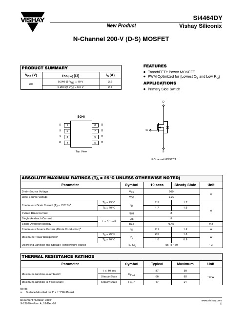
Threshold Voltage
0.8
50
0.4
40
ID = 250 mA
0.0
30
-0.4
20
Single Pulse Power
VGS(th) Variance (V) Power (W)
-0.8
10
-1.2 -50 -25
0 25 50 75 100 125 150 TJ - Temperature (_C)
Maximum Power Dissipationa
Operating Junction and Storage Temperature Range
TA = 25_C TA = 70_C
L = 0.1 mH
TA = 25_C TA = 70_C
VDS VGS
ID
IDM IAS EAS IS
PD
TJ, Tstg
0
ID = 2.2 A
2
4
6
8
10
VGS - Gate-to-Source Voltage (V)
3
元器件交易网
Si4464DY
Vishay SiliconiTERISTICS (25_C UNLESS NOTED)
Qg Qgs Qgd RG td(on)
tr td(off)
tf trr
Notes a. Pulse test; pulse width v 300 ms, duty cycle v 2%. b. Guaranteed by design, not subject to production testing.
Continuous Drain Current (TJ = 150_C)a Pulsed Drain Current Single Avalanch Current Single Avalanch Energy Continuous Source Current (Diode Conduction)a
SI4431DY中文资料
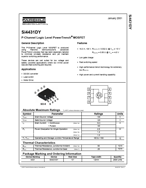
(Note 2)
Aቤተ መጻሕፍቲ ባይዱV
–0.76
–1.2
Notes: 1. RθJA is the sum of the junction-to-case and case-to-ambient thermal resistance where the case thermal reference is defined as the solder mounting surface of the drain pins. RθJC is guaranteed by design while RθCA is determined by the user's board design.
Si4431DY Rev A
元器件交易网
Si4431DY
Typical Characteristics
40 VGS = -10.0V -6.0V -ID, DRAIN CURRENT (A) 32 RDS(ON), NORMALIZED DRAIN-SOURCE ON-RESISTANCE -5.0V -4.5V -4.0V 24 -3.5V 16 -3.0V
VDS = VGS, ID = –250 µA ID = –250 µA, Referenced to 25°C VGS = –10 V, ID = –7.0 A ID = –5.5 A VGS = –4.5 V, VGS = –10 V, ID = –7.0A, TJ=125°C VGS = –10 V, VDS = –10 V, VDS = –5 V ID = –7.0 A
工业级硬盘录像机参数(1)
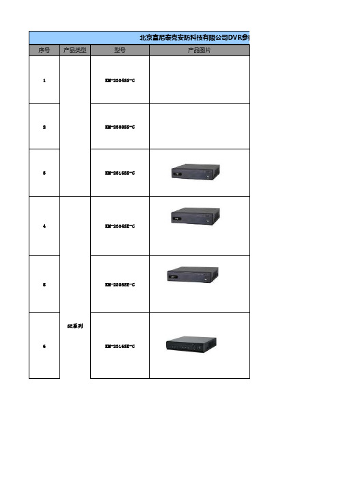
北京富尼泰克安防科技有限公司DVR参数序号产品类型型号产品图片1KM-2304SS-C2KM-2308SS-C3KM-2316SS-C4KM-2304SE-C5KM-2308SE-CSE系列6KM-2316SE-C7KM-2324SE 8KM-2304ME-B 9KM-2308ME-BME系列10KM-2316ME-C 11KM-2316ME-BH 12KM-2404MD13KM-2408MD-BL 14KM-2416MD-BL 15KM-2508HE-AL 16KM-2504HE-C 17KM-2508HE-C18KM-2516HE-CMD系列25HE系列19KM-2524HE-C 20KM-2532HE-C21KM-2508HS-C HS-C系列22KM-2516HS-C参数主要参数1)视频通道:4,音频通道:22)视频输出:高清HDMI,VGA,CVBS输出3)录像:支持960H实时录像4)回放通道:45)支持双码流,支持手机浏览6)支持SATA硬盘数量:17)机箱大小:1U小机箱1) 视频通道:82) 音频通道:23)视频输出:HDMI,VGA,CVBS同时输出4)录像: 支持D1实时录像,960H@15F录像5) 回放通道数:86)支持SATA硬盘数量:11) 视频通道:162) 音频通道:23)视频输出:HDMI,VGA,CVBS同时输出4)录像:支持CIF实时录像,960H@7F录像5) 回放通道数:166)支持SATA硬盘数量:11)视频通道:42)音频通道:43)视频输出:高清VGA1280*1024 CVBS*1,HDMI*14)录像分辨率:960H 25F5)回放通道数:46)支持SATA硬盘数量:17)支持双码流 485,报警8)机箱大小:1U小机箱1)视频通道:82)音频通道:43)视频输出:VGA; CVBS;HDMI;4)录像:支持D1实时录像,960H@15F5)回放通道数:86)支持SATA硬盘数量:17)支持双码流 485,报警8)机箱大小:1U小机箱1) 视频通道:162) 音频通道:43)视频输出:HDMI,VGA,CVBS4)录像:支持D1实时录像,960H@15F录像5) 回放通道数:166)支持SATA硬盘数量:17)支持双码流 485,报警8)机箱大小:1U小机箱1)视频通道:242)音频通道:43)视频输出:高清VGA1280*1024 CVBS*1,矩阵*14)录像分辨率:CIF 25F5)回放通道数:166)支持SATA硬盘数量:37)支持双码流 485 报警8)机箱大小:1U机箱1)视频通道:42)音频通道:43)视频输出:高清HDMI,VGA, CVBS*1,矩阵*1 4)录像:支持D1实时录像5)回放通道数:46)支持SATA硬盘数量:27)支持双码流8)机箱大小:1U机箱1)视频通道:82)音频通道:43)视频输出:高清HDMI1920*1080,VGA,CVBS*1,矩阵*14)录像:支持4D1+4CIF实时录像5)回放通道数:86)支持SATA硬盘数量:27)支持双码流8)机箱大小:1U机箱1)视频通道:162)音频通道:43)视频输出:高清HDMI1920*1080,VGA ,CVBS*1,矩阵*14)录像:支持CIF实时录像5)回放通道数:166)支持SATA硬盘数量:27)支持双码流8)机箱大小:1U机箱1)视频通道:162)音频通道:43)视频输出: 高清HDMI1920*1080,VGA1920*1080,CVBS*1,矩阵*1 4)录像:4D1+12CIF实时录像5)回放通道数:16 (4)6)支持SATA硬盘数量:27)支持双码流8)机箱大小:1U机箱1)视频通道:42)音频通道:43)视频输出:VGA*1,CVBS*1,环通,矩阵*1 4)录像分辨率:CIF 25F/D1 6F (1D1+3CIF)5)回放通道数:46)支持SATA硬盘数量:47)支持双码流8)机箱大小:标准2U机箱1)视频通道:82)音频通道:83)视频输出:VGA*1,CVBS*1,环通,矩阵*1 4)录像分辨率:CIF /D15)回放通道数:8 (4)6)支持SATA硬盘数量:47)支持双码流8)机箱大小:标准2U机箱1)视频通道:162)音频通道:163)视频输出:VGA*1,CVBS*1,环通,矩阵*1 4)录像分辨率:CIF 25F/D1 6F (4D1+12CIF) 5)回放通道数:16 (4)6)支持SATA硬盘数量:47)支持双码流8)机箱大小:标准2U机箱1)视频通道:82)音频通道:43)视频输出: 高清HDMI 1920*1080,VGA1920*1080,CVBS*1,矩阵*14)录像分辨率:D15)回放通道数:86)支持SATA硬盘数量:17)支持双码流8)机箱大小: 1U小机箱1)视频通道:42)音频通道:43)视频输出:VGA*1 CVBS*1,HDMI*1 环通,矩阵*14)录像分辨率:960H5)回放通道数:46)支持SATA硬盘数量:2(2T)7)支持双码流8)机箱大小:标准1U机箱1)视频通道:82)音频通道:43)视频输出:VGA*1 CVBS*1,HDMI*1 环通,矩阵*14)录像分辨率:960H5)回放通道数:86)支持SATA硬盘数量:2(3T)7)支持双码流8)机箱大小:标准1U机箱1)视频通道:162)音频通道:43)视频输出:VGA*1 CVBS*1,HDMI*1 环通,矩阵*14)录像分辨率:960H5)回放通道数:166)支持SATA硬盘数量:27)支持双码流8)机箱大小:标准1U机箱1)视频通道:242)音频通道:43)视频输出:HDMIx1:1920x1080;VGAx1:1920x1080; BNCx2:一路主输出,一路矩阵输出4)录像分辨率:960H5)回放通道数:16画面同时回放6)支持SATA硬盘数量:27)支持双码流8)机箱大小:1.5U机箱1)视频通道:322)音频通道:43)视频输出:HDMIx1:1920x1080;VGAx1:1920x1080;BNCx2:一路主输出,一路矩阵输出4)录像分辨率:960H5)回放通道数:16画面同时回放6)支持SATA硬盘数量:27)支持双码流8)机箱大小:1.5U机箱1) 视频通道:82) 音频通道:43)视频输出:HDMIx1:1920x1080VGAx1:1920x1080BNCx2:一路主输出,一路矩阵输出4)录像分辨率:960H5)回放通道数:8画面同时回放6)支持SATA硬盘数量:17)支持双码流8)机箱大小:1U小机箱1)视频通道:162)音频通道:43)视频输出:HDMIx1:1920x1080VGAx1:1920x1080BNCx2:一路主输出,一路矩阵输出4)录像分辨率:960H5)回放通道数:16画面同时回放6)支持SATA硬盘数量:17)支持双码流8)机箱大小:1U小机箱。
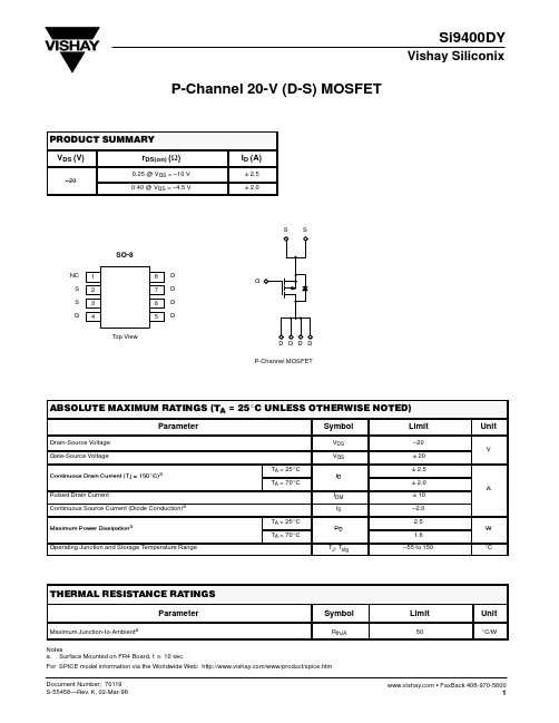
SI9400DY中文资料
80
60 0.0 40 –0.5 20
–1 –50
–25
0
25
50
75
100
125
150
0 0.001 0.01 0.1 1 10
TJ – Temperature (_C)
Normalized Thermal Transient Impedance, Junction-to-Ambient
2 1 Duty Cycle = 0.5 Normalized Effective Transient Thermal Impedance
0 0 2 4 6 8 10
VSD – Source-to-Drain Voltage (V)
VGS – Gate-to-Source Voltage (V)
1.0
Threshold Voltage
100
Single Pulse Power
0.5 V GS(th) Variance (V)
ID = 250 µA
元器件交易网
Si9400DY
Vishay Siliconix
P-Channel 20-V (D-S) MOSFET
PRODUCT SUMMARY
VDS (V)
–20
rDS(on) (W)
0.25 @ VGS = –10 V 0.40 @ VGS = –4.5 V
ID (A)
Symbol
RthJA
Limit
50
Unit
_C/W
1
元器件交易网
Si9400DY
Vishay Siliconix
SPECIFICATIONS (TJ = 25_C UNLESS OTHERWISE NOTED)
A4400交换机用户操作培训资料

ALCATELA4400用户操作及培训资料目录目录1. 4400交换机机架简介 (3)2. 4400交换机功能板简介 (4)3. 4400交换机系统命令 (6)4. 开关机方法及注意事项 (7)5. 4400交换机系统数据管理 (8)6. mgr 管理工具 (9)7. 分机管理 (10)8. 组管理 (13)9. 中继管理 (15)10. 号码编译 (20)11. 类别管理 (23)1.4400交换机机架简介左图为4400机架ACT 是用于插交换机功能板的分架。
ACT编号从0开始(如:ACT0、ACT1)。
4400有两种ACT,ACT14和ACT28。
ACT14有14个槽口,可插14块功能板(如左图的ACT1);ACT28有28个槽口,可插28块功能板(左图中的ACT2)。
系统有固定的设备号(即物理地址),设备号由ACT号、槽口号和功能板上的电路号组成(如:ACT0上的第5槽口的eUA32板上的第一个端口的设备号为0-5-0,ACT1上的第11槽口的eUA32板上的最后一个设备号为1-11-31)2.4400交换机功能板简介CUP-3、CUP-6→主控板(板上有CPU、硬盘、内存条等主控设备)eZ32、Z24→模拟用户板(板上有32个或24个模拟用户端口,通过交换机后板电缆经配线架接普通电话机)UA16、eUA32→数字用户板(板上有16个或32个数字用户端口, 通过交换机后板电缆接ALCATEL的数字设备,如:4004话机、4010话机、4020话机、4029话机、4039话务台及其他数字设备)NDDI→模拟中继板(板上有8个模拟中继端口, 通过交换机后板电缆接电信中继)PRA2→ T2数字中继板式(板上有30个T2数字中继通道, 通过交换机后板电缆或同轴电缆接电信中继)VG→语音板(板上可插闪存卡,提供系统的语音提示及保留音乐)SUVG→ SU语音板(板上可插闪存卡,提供系统的语音提示及保留音乐,并提供双音频接收功能)MMSFD→软驱板(板上有1.44M软驱,通过软驱可对系统进行数据备份)INTOF→ ACT分架接口板(各ACT分架通过此板与主ACT-CPU分架进行联接)GPA2 →功能辅助板(提供29方会议功能,并可插闪存卡,提供系统的语音提示及保留音乐或双音频接收)VPS35→语音信箱板(提供系统内置语音信箱服务功能)DECT4→内部移动电话板(提供内部移动电话功能)BRA2→ T0/S0接口板(板上有8个T0/S0端口,通过后板电缆接2B+D中继和用户)PCM2→ PCM数字中继板(板上有30个PCM数字中继通道, 通过同轴电缆接电信的中国一号中继)EMTL→ Tie-Line中继板(提供Tie-Line组网功能)LIOE→ IP接口板(提供系统IP电话接口及其它IP接口)LIOB→ DDN接口板(提供 64K/128K DDN中继接口)IO2→输入输出板(提供系统额外的辅助接口)RT2→远端ACT分架接口板(远端ACT分架通过此板与主ACT分架进行联接)3. 4400交换机系统命令登录系统命令和密码退出系统命令a4400a> exit系统复位命令a4400a> shutdown –r now◆慎用,系统将停机后重新启动。
全国的只读类光盘复制单位光盘来源识别码SID码一览表--实用
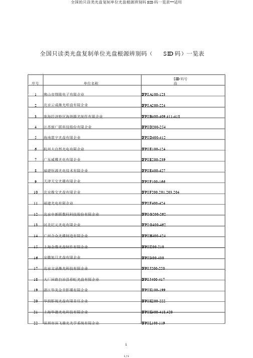
全国只读类光盘复制单位光盘根源辨别码(SID码)一览表序号单位名称SID码号段1 佛山市锋隆电子有限企业IFPI A100-1232 北京云成激光唱盘有限企业IFPI A200-2243 珠海经济特区海纳激光制作有限企业IFPI B400-409,411-4184 江苏新广联科技股份有限企业IFPI D200-2545 海南震宇光盘有限企业IFPI D400-4126 杭州大自然光电有限企业IFPI E100-1247 广东威雅光电有限企业IFPI E200-2398 福建恒源光电技术有限企业IFPI E400-4279 天津天宝光碟有限企业IFPI F100-16610 北京维宝光盘有限企业IFPI F200,201,203,20411 福建光电有限企业IFPI F400-42412 北京中新联数码科技股份有限企业IFPI G200-26213 河北纪元光电有限企业IFPI G400-46214 广州合众光碟制造有限企业IFPI H400-42415 上海金像光盘制作有限企业IFPI I200-21016 安徽旭日光盘有限企业IFPI I400-43017 北京文录激光科技有限企业IFPI J200-22018 大厂回族自治县彩虹光盘有限企业IFPI J400-41719 湛江华美金音影碟有限企业IFPI K100-19920 华韵影视光盘有限责任企业IFPI K200-22221 上海华德光电科技有限企业IFPI K400-418,42022 深圳市深飞激光光学系统有限企业IFPI L100-11923 湖北东湖光盘技术有限责任企业IFPI L200-23324 烟台宏正光电传媒有限企业IFPI L400-42025 湖南省远景光电实业有限企业IFPI M200-21426 广州永通音像制作有限企业IFPI N100-14227 浙江华虹光电企业有限企业IFPI N200-24228 天津民族文化光盘有限责任企业IFPI N400-40729 安阳飞音电脑数码制作有限企业IFPI O400-402,404-41230 深圳市致诚威光盘制作有限企业IFPI P200-24031 江西金科光盘有限企业IFPI P400-44132 新会佩斯光电有限企业IFPI Q100-12333 东方光盘制造有限企业IFPI Q200-21134 广东环宇音像有限企业IFPI Q400-41935 佛山市南海明珠影音企业IFPI R100-11936 北京大百科光盘有限责任企业IFPI R200-20637 普宁市金盘科技有限企业IFPI R400-43138 梅州市嘉应万达激光有限企业IFPI S200-22939 吉林庆达光盘科技有限责任企业IFPI S400-42140 珠海华光镭射唱片有限企业IFPI T100-11641 珠海兰迪光盘制作有限企业IFPI U400-42242 茂名市(水东)佳和科技发展企业IFPI V100-12843 北京中联光碟有限企业IFPI V200-23544 海南中舟电子光碟有限企业IFPI V400-41245 中山市力华光碟制造有限企业IFPI W200-22646 广西迪美科技发展有限企业IFPI W400-40647 北京海传光盘有限企业IFPI X200-22548 上海新索音乐有限企业IFPI X400-43649 上海结合光盘有限企业IFPI Y100-110,112-13350 北京保利星数据光盘有限企业IFPI Y200-24351 深圳市紫麓科技有限企业IFPI Y400-41852 淄博崇正镭射音像有限企业IFPI Z100-11553 大连华录影音实业有限企业IFPI Z200-25554 广东新飞仕激光科技有限企业IFPI Z400-44455 浙江天创光电有限企业IFPI CA100-12156 广东中唱一帆科技发展有限企业IFPI CA200-22757 广东昊轩科技有限企业IFPI CA400-41958 西安东方华文光盘制造有限责任企业IFPI CA500-50759 扬州广德信息有限企业IFPI CA600-60960 深圳市中新联光电有限企业IFPI CA700-74861 佛山市顺德区润生电子有限企业IFPI CA800-82662 北京凯地蓝光数码科技有限企业IFPI CA900-91363 北京中录同方文化流传有限企业IFPI CB100-10364 宁夏新海利视盘有限企业IFPI CB200-20665 四川省蓥山数码科技文化发展有限企业IFPI CB300-31766 深圳市嘉长源实业有限企业IFPI CB400-41367 苏州新海博数码科技有限企业IFPI CB500-52768 东莞市威雅光电有限企业IFPI CB600-60569 揭阳市东煌文化发展有限企业IFPI CB700-70570 广东中凯科技发展有限企业IFPI CB800-81971 贵州微讯科技发展有限企业IFPI CB900-90372 潮州市连思科技发展有限企业IFPI CC100-10373 桂林鸿瑞科技发展有限企业IFPI CC400-42374 云南云滇光盘有限企业IFPI CC500-50675 南通中兴多媒体有限企业IFPI CC600-60276 广州金诚潮发展有限企业IFPI CC700-70677 广东奥林磁电实业有限企业IFPI CC800-80378 广东省粤东磁电有限企业IFPI CC900-90779 广东粤华磁电实业有限企业IFPI ADL00-0380 广东洽丰文化科技有限企业IFPI ADM00-0881 深圳市深宇激光有限企业IFPI ADN00-1282 深圳市冠愉光电科技有限企业IFPI ADP00-1183 广东飞雄电影投资刊行有限企业IFPI ADQ00-3484 广东格莱德科技发展有限企业IFPI ADR00-0985 河源市港华激光有限企业IFPI ADT00-0586 广东太平洋数码科技有限企业IFPI ADU00-1387 佛山市新金声电子有限企业IFPI ADV00-2288 广东金晖影音有限企业IFPI ADW00-1189 广东东国科贸有限企业IFPI ADY00-2590 江苏新海燕光电有限企业IFPI ADZ00-0491 广西大海世纪音像有限企业IFPI AEA00-0592 广东好家庭影视音像制作有限企业IFPI AEB00-1593 广东创科科技股份有限企业IFPI AEC00-2694 广州旌凡光盘有限企业IFPI AED00-2295 重庆银杏光盘有限责任企业IFPI AEE00-5196 东莞市新广联光电科技有限企业IFPI AEF00-1497 汕头市宏图文化流传有限企业IFPI AEG00-1698 阳江市德恩富科技有限企业IFPI AEH00-0499 普宁市粤统统讯有限企业IFPI ZAA00-03 100 上海新汇时代光盘技术有限企业IFPI ZAB00-05 101 中影克莱斯德数字媒介有限责任企业IFPI ZAC00-28 102 福建嘉达光电有限企业IFPI ZAD00-01 103 江西蓝海光盘有限企业IFPI ZAE00-39104 佛山市南海区腾辉科技有限企业IFPI ZAF00-13105 广西祥云科技发展有限企业IFPI ZAG00-17106 广州市富众光电技术有限企业IFPI ZAH00-05107 中山东龙电子科技开发有限企业IFPI ZAJ00-06108 广州市好影电子科技有限企业IFPI ZAK00-05109 北京华信翔龙光盘有限企业IFPI ZAL00-12110 普宁市益宁科技有限企业IFPI ZAM00-01111 中航御铭(安阳)科技有限企业IFPI ZAN00-13说明:光盘根源辨别码( SID码)是经过对激光数码储藏片注塑模具定模镜面板规定地点进行蚀刻的方式,压制在激光数码储藏片表面的一组 4位数或 5位数编码。
Si9110DY-T1中文资料

High-Voltage Switchmode ControllersFEATURESD 10- to 120-V Input Range D Current-Mode ControlD High-Speed, Source-Sink Output Drive DHigh Efficiency Operation (> 80%)D Internal Start-Up Circuit D Internal Oscillator (1 MHz)D SHUTDOWN and RESETD Reference SelectionSi9110 − "1%Si9111 − "10%DESCRIPTIONThe Si9110/9111 are BiC/DMOS integrated circuits designed for use as high-performance switchmode controllers. A high-voltage DMOS input allows the controller to work over a wide range of input voltages (10- to 120-VDC). Current-mode PWM control circuitry is implemented in CMOS to reduce internal power consumption to less than 10 mW.A push-pull output driver provides high-speed switching for MOSPOWER devices large enough to supply 50 W of outputpower. When combined with an output MOSFET and transformer, the Si9110/9111 can be used to implement single-ended power converter topologies (i.e., flyback,forward, and cuk).The Si9110/9111 are available in a standard 14-pin plastic DIP and standard or lead (Pb)-free SOIC package, and are specified over the and industrial, D suffix (−40 to 85_C)temperature ranges.FUNCTIONAL BLOCK DIAGRAMFB COMP DISCHARGEBIASV REFV CC+V INOSC OUTOSC INPre-Regulator/Start-UpABSOLUTE MAXIMUM RATINGSVoltages Referenced to −V IN (Note: V CC < +V IN + 0.3 V)V CC 15 V . . . . . . . . . . . . . . . . . . . . . . . . . . . . . . . . . . . . . . . . . . . . . . . . . . . . . . . . . +V IN 120 V . . . . . . . . . . . . . . . . . . . . . . . . . . . . . . . . . . . . . . . . . . . . . . . . . . . . . . . Logic Inputs (RESET,SHUTDOWN, OSC IN, OSC OUT)−0.3 V to V CC + 0.3 V . . . . . . . . . . . . . . . Linear Inputs(FEEDBACK, SENSE, BIAS, V REF )−0.3 V to V CC + 0.3 V . . . . . . . . . . . . . . . HV Pre-Regulator Input Current (continuous) 5 mA . . . . . . . . . . . . . . . . . . . . . Storage Temperature −65 to 150_C . . . . . . . . . . . . . . . . . . . . . . . . . . . . . . . . . . Operating Temperature −40 to 85_C. . . . . . . . . . . . . . . . . . . . . . . . . . . . . . . . . Junction Temperature (T J )150_C . . . . . . . . . . . . . . . . . . . . . . . . . . . . . . . . . . . . Power Dissipation (Package)a14-Pin Plastic DIP (J Suffix)b 750 mW . . . . . . . . . . . . . . . . . . . . . . . . . . . . . . . . 14-Pin SOIC (Y Suffix)c 900 mW . . . . . . . . . . . . . . . . . . . . . . . . . . . . . . . . . . . . Thermal Impedance (Q JA )14-Pin Plastic DIP 167_C/W . . . . . . . . . . . . . . . . . . . . . . . . . . . . . . . . . . . . . . . . . 14-Pin SOIC 140_C/W . . . . . . . . . . . . . . . . . . . . . . . . . . . . . . . . . . . . . . . . . . . . . Notesa.Device mounted with all leads soldered or welded to PC board.b.Derate 6 mW/_C above 25_C.c.Derate 7.2 mW/_C above 25_C.RECOMMENDED OPERATING RANGEVoltages Referenced to −V INV CC 9.5 V to 13.5 V . . . . . . . . . . . . . . . . . . . . . . . . . . . . . . . . . . . . . . . . . . . . . . . . +V IN 10 V to 120 V . . . . . . . . . . . . . . . . . . . . . . . . . . . . . . . . . . . . . . . . . . . . . . . . f OSC 40 kHz to 1 MHz. . . . . . . . . . . . . . . . . . . . . . . . . . . . . . . . . . . . . . . . . . . . . R OSC 25 k W to 1 M W . . . . . . . . . . . . . . . . . . . . . . . . . . . . . . . . . . . . . . . . . . . . . . Linear Inputs 0 to V CC − 3 V . . . . . . . . . . . . . . . . . . . . . . . . . . . . . . . . . . . . . . . . Digital Inputs 0 to V CC. . . . . . . . . . . . . . . . . . . . . . . . . . . . . . . . . . . . . . . . . . . . . SPECIFICATIONS aTest ConditionsUnless Otherwise SpecifiedDISCHARGE = D Suffix−40 to 85_CParameterSymbol−V IN = 0 V V CC = 10 V, +V IN = 48 V R BIAS = 390 k W , R OSC = 330 k WTemp b Min d Typ c Max dUnitReferenceSi9110Room 3.92 4.0 4.08OSC IN = − V IN (OSC Disabled)Si9111Room 3.60 4.04.40Output VoltageV RSi9110Full 3.86 4.14VR L = 10 M WSi9111Full 3.52 4.46Output Impedance e Z OUT Room 153045k W Short Circuit Current I SREF V REF = −V INRoom 70100130m A Temperature Stability eT REFFull0.50 1.0mV/_C OscillatorMaximum Frequency e f MAX R OSC = 0Room 13MHz R OSC = 330 k, See Note f Room 80100120Initial Accuracy f OSC R OSC = 150 k, See Note f Room 160200240kHz Voltage Stability D f/f D f/f=f(13.5 V) − f(9.5 V)/ f(9.5 V)Room 1015%Temperature Coefficient eT OSCFull200500ppm/_CError AmplifierFB Tied to COMP Si9110Room 3.96 4.00 4.04Feedback Input Voltage V FB OSC IN = − V IN (OSC Disabled)Si9111Room 3.604.00 4.40V Input BIAS Current I FB OSC IN = − V IN , V FB = 4 VRoom 25500nA Input OFFSET Voltage V OS Room "15"40mV Open Loop Voltage Gain e A VOL OSC IN = Room 6080dB Unity Gain Bandwidth e BW − V IN (OSC Disabled)Room 1 1.3MHz Dynamic Output Impedance e Z OUT Room 10002000W Source (V FB = 3.4 V)Room −2.0−1.4Output Current I OUT Sink (V FB = 4.5 V)Room 0.120.15mA Power Supply Rejection PSRR9.5 V v V CC v 13.5 VRoom5070dBSPECIFICATIONS aD Suffix−40 to 85_CTest ConditionsDISCHARGE = ParameterUnitMax dTyp c Min d Temp b Unless Otherwise Specified−V IN = 0 V V CC = 10 V, +V IN = 48 V R BIAS = 390 k W , R OSC = 330 k WSymbolCurrent LimitThreshold Voltage V SOURCEV FB = 0 VRoom 1.01.2 1.4V Delay to Output et dV SENSE = 1.5 V, See Figure 1Room100150nsPre-Regulator/Start-UpInput Voltage+V IN I IN = 10 m A Room 120V Input Leakage Current +I IN V CC w 9.4 VRoom 10m A Pre-Regulator Start-Up Current I START Pulse Width v 300 m s, V CC = V ULVORoom 815mAV CC Pre-Regulator Turn-Off Threshold Voltage V REG I PRE-REGULATOR = 10 m ARoom 7.88.69.4Undervoltage Lockout V UVLO Room 7.08.18.9VV REG −V UVLOV DELTARoom0.30.6SupplySupply Current I CC C LOAD < 75 pF (Pin 4)Room 0.450.6 1.0mA Bias CurrentI BIASRoom101520m ALogicSHUTDOWN Delay e t SD C L = 500 pF, V SENSE −V IN , See Figure 2Room 50100SHUTDOWN Pulse Width e t SW See Figure 3Room 50RESET Pulse Width et RW Room 50nsLatching Pulse WidthSHUTDOWN and RESET Low e t LW See Figure 3Room 25Input Low Voltage V IL Room 2.0Input High VoltageV IH Room 8V Input Current Input Voltage High I IH V IN = 10 V Room 15Input Current Input Voltage LowI ILV IN = 0 V Room−35−25m AOutputOutput High Voltage V OH I OUT = −10 mA Room Full 9.79.5Output Low Voltage V OL I OUT = 10 mARoom Full 0.300.50VOutput Resistance R OUT I OUT = 10 mA, Source or SinkRoom Full 20253050W Rise Time e t r Room 4075Fall Time et fC L = 500 pFRoom4075nsNotesa.Refer to PROCESS OPTION FLOWCHART for additional information.b.Room = 25_C, Full = as determined by the operating temperature suffix.c.Typical values are for DESIGN AID ONLY , not guaranteed nor subject to production testing.d.The algebraic convention whereby the most negative value is a minimum and the most positive a maximum.e.Guaranteed by design, not subject to production test.f.C STRAY Pin 8 = v 5 pF.TIMING WAVEFORMSFIGURE 3.TYPICAL CHARACTERISTICS+V IN vs. +I IN at Start-UpOutput Switching Frequency vs.Oscillator Resistance(V )140120100806040200101520+I IN (mA)+V I N (H z )1 M10 k100 k10 k100 k 1 Mr OSC (W )f O U T FIGURE 4.FIGURE 5.BIAS FB +V IN COMP SENSE RESET OUTPUTSHUTDOWN −V IN V REF V CCDISCHARGE OSC OUTOSC INDual-In-Line and SOIC1234567141312111098Top ViewPIN CONFIGURATIONS AND ORDERING INFORMATIONORDERING INFORMATIONPart NumberTemperature Range PackageSi9110DY Si9110DY -T1Si9110DY -T1—E3Si9111DY SOIC-14Si9111DY -T1CSi9111DY -T1—E3−40 to 85_Si9110DJ Si9110DJ-T1PDIP 14Si9111DJ PDIP-14Si9111DJ-T1DETAILED DESCRIPTIONPre-Regulator/Start-Up SectionDue to the low quiescent current requirement of theSi9110/9111 control circuitry, bias power can be supplied from the unregulated input power source, from an external regulated low-voltage supply, or from an auxiliary “bootstrap”winding on the output inductor or transformer.When power is first applied during start-up, +V IN (pin 2) will draw a constant current. The magnitude of this current is determined by a high-voltage depletion MOSFET device which is connected between +V IN and V CC (pin 6). This start-up circuitry provides initial power to the IC by charging an external bypass capacitance connected to the V CC pin. The constant current is disabled when V CC exceeds 8.6 V. If V CC is not forced to exceed the 8.6-V threshold, then V CC will be regulated to a nominal value of 8.6 V by the pre-regulator circuit.As the supply voltage rises toward the normal operating conditions, an internal undervoltage (UV) lockout circuit keeps the output driver disabled until V CC exceeds the undervoltage lockout threshold (typically 8.1 V). This guarantees that the control logic will be functioning properly and that sufficient gate drive voltage is available before the MOSFET turns on.The design of the IC is such that the undervoltage lockout threshold will be at least 300 mV less than the pre-regulator turn-off voltage. Power dissipation can be minimized by providing an external power source to V CC such that the constant current source is always disabled.Note: During start-up or when V CC drops below 8.6V the start-up circuit is capable of sourcing up to 20 mA. This maylead to a high level of power dissipation in the IC (for a 48-V input, approximately 1 W). Excessive start-up time caused by external loading of the V CC supply can result in device damage. Figure 6 gives the typical pre-regulator current at BiC/DMOS as a function of input voltage.BIASTo properly set the bias for the Si9110/9111, a 390-k W resistor should be tied from BIAS (pin 1) to −V IN (pin 5). This determines the magnitude of bias current in all of the analog sections and the pull-up current for the SHUDOWN and RESET pins. The current flowing in the bias resistor is nominally 15m A.Reference SectionThe reference section of the Si9110 consists of a temperature compensated buried zener and trimmable divider network.The output of the reference section is connected internally to the non-inverting input of the error amplifier. Nominal reference output voltage is 4 V. The trimming procedure that is used on the Si9110 brings the output of the error amplifier (which is configured for unity gain during trimming) to within "1% of 4 V.This compensates for input offset voltage in the error amplifier.The output impedance of the reference section has been purposely made high so that a low impedance external voltage source can be used to override the internal voltage source, if desired, without otherwise altering the performance of the device.DETAILED DESCRIPTION (CONT’D)Applications which use a separate external reference, such as non-isolated converter topologies and circuits employing optical coupling in the feedback loop, do not require a trimmed voltage reference with 1% accuracy. The Si9111accommodates the requirements of these applications at a lower cost, by leaving the reference voltage untrimmed. The 10% accurate reference thus provided is sufficient to establish a dc bias point for the error amplifier.Error AmplifierClosed-loop regulation is provided by the error amplifier, which is intended for use with “around-the-amplifier” compensation.A MOS differential input stage provides for low input current.The noninverting input to the error amplifier (V REF ) is internally connected to the output of the reference supply and should be bypassed with a small capacitor to ground.Oscillator SectionThe oscillator consists of a ring of CMOS inverters, capacitors,and a capacitor discharge switch. Frequency is set by an external resistor between the OSC IN and OSC OUT pins.(See Figure 5 for details of resistor value vs. frequency.) The DISCHARGE pin should be tied to −V IN for normal internal oscillator operation. A frequency divider in the logic section limits switch duty cycle to v 50% by locking the switching frequency to one half of the oscillator frequency.Remote synchronization is accomplished by capacitive coupling of a positive SYNC pulse into the OSC IN (pin 8)terminal. For a 5-V pulse amplitude and 0.5-m s pulse width,typical values would be 100 pF in series with 3 k W to pin 8.SHUTDOWN and RESETSHUTDOWN (pin 11) and RESET (pin 12) are intended for overriding the output MOSFET switch via external controllogic. The two inputs are fed through a latch preceding the output switch. Depending on the logic state of RESET,SHUTDOWN can be either a latched or unlatched input. The output is off whenever SHUTDOWN is low. By simultaneously having SHUTDOWN and RESET low, the latch is set and SHUTDOWN has no effect until RESET goes high. The truth table for these inputs is given in Table 1.Table 1: Truth Table for the SHUTDOWN and RESET PinsBoth pins have internal current source pull-ups and should be left disconnected when not in use. An added feature of the current sources is the ability to connect a capacitor and an open-collector driver to the SHUTDOWN or RESET pins to provide variable shutdown time.Output DriverThe push-pull driver output has a typical on-resistance of 20 W .Maximum switching times are specified at 75 ns for a 500-pF load. This is sufficient to directly drive MOSFETs such as the 2N7004, 2N7005, IRFD120 and IRFD220. Larger devices can be driven, but switching times will be longer, resulting in higher switching losses. In order to drive large MOSPOWER devices,it is necessary to use an external driver IC, such as the Vishay Siliconix D469A. The D469A can switch very large devices such as the SMM20N50 (500 V, 0.3 W ) in approximately 100 ns.APPLICATIONSGND−48 V+5 V@ 0.75 A−5 V@ 0.25 ACC FIGURE 6.5-Watt Power Supply for T elecom Applications。
SI4134DY中文资料
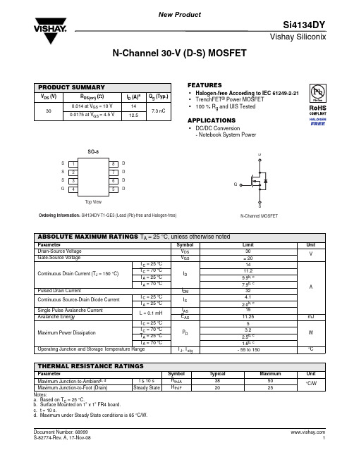
Vishay SiliconixSi4134DYN-Channel 30-V (D-S) MOSFETFEATURES•Halogen-free According to IEC 61249-2-21 •TrenchFET ® Power MOSFET •100 % R g and UIS TestedAPPLICATIONS•DC/DC Conversion- Notebook System PowerPRODUCT SUMMARYV DS (V)R DS(on) (Ω)I D (A)a Q g (Typ.)300.014 at V GS = 10 V 147.3 nC0.0175 at V GS = 4.5 V12.5Notes:a.Based on T C = 25 °C.b.Surface Mounted on 1" x 1" FR4 board.c.t = 10 s.d.Maximum under Steady State conditions is 85 °C/W.ABSOLUTE MAXIMUM RATINGS T A = 25 °C, unless otherwise notedParameter Symbol Limit UnitDrain-Source Voltage V DS 30VGate-Source Voltage V GS ± 20Continuous Drain Current (T J = 150 °C)T C = 25 °C I D14AT C = 70 °C 11.2T A = 25 °C 9.9b, c T A = 70 °C 7.9b, cPulsed Drain Current I DM 32Continuous Source-Drain Diode CurrentT C = 25 °C I S 4.1T A = 25 °C 2.0b, cSingle Pulse Avalanche CurrentL = 0.1 mHI AS 15Avalanche Energy E AS 11.25mJ Maximum Power Dissipation T C = 25 °C P D 5WT C = 70 °C 3.2T A = 25 °C 2.5b, c T A = 70 °C 1.6b, cOperating Junction and Storage T emperature Range T J , T stg - 55 to 150°C THERMAL RESISTANCE RATINGSParameter Symbol Typical Maximum UnitMaximum Junction-to-Ambient b, dt ≤ 10 s R thJA 3850°C/WMaximum Junction-to-Foot (Drain)Steady State R thJF 2025Vishay SiliconixSi4134DYNotes:a. Pulse test; pulse width ≤ 300 µs, duty cycle ≤ 2 %b. Guaranteed by design, not subject to production testing.Stresses beyond those listed under “Absolute Maximum Ratings” may cause permanent damage to the device. These are stress ratings only, and functional operation of the device at these or any other conditions beyond those indicated in the operational sections of the specifications is not implied. Exposure to absolute maximum rating conditions for extended periods may affect device reliability.SPECIFICATIONS T J = 25 °C, unless otherwise notedParameter Symbol Test Conditions Min. Typ.Max.UnitStaticDrain-Source Breakdown Voltage V DS V GS = 0 V , I D = 250 µA30V V DS Temperature Coefficient ΔV DS /T J I D = 250 µA33mV/°C V GS(th) T emperature Coefficient ΔV GS(th)/T J - 5.0Gate-Source Threshold Voltage V GS(th)V DS = V GS , I D = 250 µA 1.2 2.5V Gate-Source LeakageI GSS V DS = 0 V , V GS = ± 20 V ± 100nA Zero Gate Voltage Drain Current I DSS V DS = 30 V , V GS = 0 V 1µA V DS = 30 V, V GS = 0 V, T J = 55 °C10On-State Drain Current aI D(on) V DS ≥ 5 V , V GS = 10 V 20A Drain-Source On-State Resistance a R DS(on)V GS = 10 V, I D = 10 A 0.01150.014ΩV GS = 4.5 V , I D = 7 A 0.01450.0175Forward T ransconductance a g fsV DS = 15 V , I D = 10 A24SDynamic bInput Capacitance C iss V DS = 15 V , V GS = 0 V , f = 1 MHz846pFOutput CapacitanceC oss 187Reverse Transfer Capacitance C rss 72Total Gate Charge Q g V DS = 15 V , V GS = 10 V , ID = 10 A 15.423nC V DS = 15 V , V GS = 4.5 V , I D = 10 A 7.311Gate-Source Charge Q gs 2.3Gate-Drain Charge Q gd 2.2Gate Resistance R g f = 1 MHz0.20.8 1.6ΩTurn-On Delay Time t d(on) V DD = 15 V , R L = 1.5 ΩI D ≅ 10 A, V GEN = 4.5 V , R g = 1 Ω1530ns Rise Timet r 1224Turn-Off Delay Time t d(off) 1326Fall Timet f 1020Turn-On Delay Time t d(on) V DD = 15 V , R L = 1.5 Ω I D ≅ 10 A, V GEN = 10 V , R g = 1 Ω918Rise Timet r 918Turn-Off Delay Time t d(off) 1428Fall Timet f816Drain-Source Body Diode Characteristics Continuous Source-Drain Diode Current I S T C = 25 °C4.2A Pulse Diode Forward Current a I SM 32Body Diode VoltageV SD I S = 3 A0.78 1.2V Body Diode Reverse Recovery Time t rr I F = 10 A, dI/dt = 100 A/µs, T J = 25 °C1734ns Body Diode Reverse Recovery Charge Q rr 9.519nC Reverse Recovery Fall Time t a 10nsReverse Recovery Rise Timet b7On-Resistance vs. Drain Current and Gate VoltageGate ChargeOn-Resistance vs. Junction TemperatureThreshold VoltageOn-Resistance vs. Gate-to-Source VoltageSingle Pulse Power, Junction-to-AmbientVishay SiliconixSi4134DYTYPICAL CHARACTERISTICS 25°C, unless otherwise noted* The power dissipation P D is based on T J(max) = 150 °C, using junction-to-case thermal resistance, and is more useful in settling the upper dissipation limit for cases where additional heatsinking is used. It is used to determine the current rating, when this rating falls below the package limit.Current Derating*Vishay SiliconixSi4134DYTYPICAL CHARACTERISTICS 25°C, unless otherwise notedVishay Siliconix maintains worldwide manufacturing capability. Products may be manufactured at one of several qualified locations. Reliability data for Silicon Technology and Package Reliability represent a composite of all qualified locations. For related documents such as package/tape drawings, part marking, and reliability data, see /ppg?68999.Disclaimer Legal Disclaimer NoticeVishayAll product specifications and data are subject to change without notice.Vishay Intertechnology, Inc., its affiliates, agents, and employees, and all persons acting on its or their behalf (collectively, “Vishay”), disclaim any and all liability for any errors, inaccuracies or incompleteness contained herein or in any other disclosure relating to any product.Vishay disclaims any and all liability arising out of the use or application of any product described herein or of any information provided herein to the maximum extent permitted by law. The product specifications do not expand or otherwise modify Vishay’s terms and conditions of purchase, including but not limited to the warranty expressed therein, which apply to these products.No license, express or implied, by estoppel or otherwise, to any intellectual property rights is granted by this document or by any conduct of Vishay.The products shown herein are not designed for use in medical, life-saving, or life-sustaining applications unless otherwise expressly indicated. Customers using or selling Vishay products not expressly indicated for use in such applications do so entirely at their own risk and agree to fully indemnify Vishay for any damages arising or resulting from such use or sale. Please contact authorized Vishay personnel to obtain written terms and conditions regarding products designed for such applications.Product names and markings noted herein may be trademarks of their respective owners.元器件交易网。
- 1、下载文档前请自行甄别文档内容的完整性,平台不提供额外的编辑、内容补充、找答案等附加服务。
- 2、"仅部分预览"的文档,不可在线预览部分如存在完整性等问题,可反馈申请退款(可完整预览的文档不适用该条件!)。
- 3、如文档侵犯您的权益,请联系客服反馈,我们会尽快为您处理(人工客服工作时间:9:00-18:30)。
SPICE Device Model Si4900DY Vishay Siliconix N-Channel 60-V (D-S) MOSFET
CHARACTERISTICS
• N-Channel Vertical DMOS • Macro Model (Subcircuit Model) • Level 3 MOS • Apply for both Linear and Switching Application • Accurate over the −55 to 125°C Temperature Range • Model the Gate Charge, Transient, and Diode Reverse Recovery Characteristics
DESCRIPTION
The attached spice model describes the typical electrical characteristics of the n-channel vertical DMOS. The subcircuit model is extracted and optimized over the −55 to 125°C temperature ranges under the pulsed 0-V to 10-V gate drive. The saturated output impedance is best fit at the gate bias near the threshold voltage. A novel gate-to-drain feedback capacitance network is used to model the gate charge characteristics while avoiding convergence difficulties of the switched Cgd model. All model parameter values are optimized to provide a best fit to the measured electrical data and are not intended as an exact physical interpretation of the device.
V A 0.046 0.059 15 0.80 Ω S V
Drain-Source On-State Resistance a Forward Transconductance a Diode Forward Voltage a
Dynamic b
Input Capacitance Output Capacitance Reverse Transfer Capacitance Total Gate Charge Gate-Source Charge Gate-Drain Charge Ciss Coss Crss Qg Qgs Qgd VDS = 30 V, VGS = 10 V, ID = 4.3 A VDS = 15 V, VGS = 0 V, f = 1 MHz 732 65 28 11 5.6 VDS = 30 V, VGS = 4.5 V, ID = 4.3 A 2.3 2.6 665 75 40 13 6 2.3 2.6 nC pF
3
SUBCIRCUIT MODEL SCHEMATIC
This document is intended as a SPICE modeling guideline and does not constitute a commercial product data sheet. Designers should refer to the appropriate data sheet of the same number for guaranteed specification limits. Document Number: 73237 S-50392Rev. A, 14-Mar-05 1
元器件交易网
SPICE Device Model Si4900DY Vishay Siliconix
COMPARISON OF MODEL WITH MEASURED DATA (TJ=25°C UNLESS OTHERWISE NOTED)
Document Number: 73237 S-50392Rev. A, 14-Mar-05
Notes a. Pulse test; pulse width ≤ 300 µs, duty cycle ≤ 2%. b. Guaranteed by design, not subject to production testing.
2
Document Number: 73237 S-50392Rev. A, 14-Mar-05
元器件交易网
SPICE Device Model Si4900DY Vishay Siliconix
SPECIFICATIONS (TJ = 25°C UNLESS OTHERWISE NOTED) Parameter Static
Gate Threshold Voltage On-State Drain Current
aSymbolຫໍສະໝຸດ Test Condition
Simulated Data
2 105 0.046 0.057 16 0.80
Measured Data
Unit
VGS(th) ID(on) rDS(on) gfs VSD
VDS = VGS, ID = 250 µA VDS ≥ 5 V, VGS = 10 V VGS = 10 V, ID = 4.3 A VGS = 4.5 V, ID = 3.9 A VDS = 15 V, ID = 4.3 A IS = 1.7 A, VGS = 0 V
